EP4056302A1 - Three-dimensional powder bed fusion additive manufacturing apparatus and three-dimensional powder bed fusion additive manufacturing method - Google Patents
Three-dimensional powder bed fusion additive manufacturing apparatus and three-dimensional powder bed fusion additive manufacturing method Download PDFInfo
- Publication number
- EP4056302A1 EP4056302A1 EP22160844.1A EP22160844A EP4056302A1 EP 4056302 A1 EP4056302 A1 EP 4056302A1 EP 22160844 A EP22160844 A EP 22160844A EP 4056302 A1 EP4056302 A1 EP 4056302A1
- Authority
- EP
- European Patent Office
- Prior art keywords
- powder
- image
- squeegee
- layer
- dimensional
- Prior art date
- Legal status (The legal status is an assumption and is not a legal conclusion. Google has not performed a legal analysis and makes no representation as to the accuracy of the status listed.)
- Pending
Links
Images







Classifications
-
- B—PERFORMING OPERATIONS; TRANSPORTING
- B22—CASTING; POWDER METALLURGY
- B22F—WORKING METALLIC POWDER; MANUFACTURE OF ARTICLES FROM METALLIC POWDER; MAKING METALLIC POWDER; APPARATUS OR DEVICES SPECIALLY ADAPTED FOR METALLIC POWDER
- B22F10/00—Additive manufacturing of workpieces or articles from metallic powder
- B22F10/80—Data acquisition or data processing
- B22F10/85—Data acquisition or data processing for controlling or regulating additive manufacturing processes
-
- B—PERFORMING OPERATIONS; TRANSPORTING
- B22—CASTING; POWDER METALLURGY
- B22F—WORKING METALLIC POWDER; MANUFACTURE OF ARTICLES FROM METALLIC POWDER; MAKING METALLIC POWDER; APPARATUS OR DEVICES SPECIALLY ADAPTED FOR METALLIC POWDER
- B22F10/00—Additive manufacturing of workpieces or articles from metallic powder
- B22F10/20—Direct sintering or melting
- B22F10/28—Powder bed fusion, e.g. selective laser melting [SLM] or electron beam melting [EBM]
-
- B—PERFORMING OPERATIONS; TRANSPORTING
- B22—CASTING; POWDER METALLURGY
- B22F—WORKING METALLIC POWDER; MANUFACTURE OF ARTICLES FROM METALLIC POWDER; MAKING METALLIC POWDER; APPARATUS OR DEVICES SPECIALLY ADAPTED FOR METALLIC POWDER
- B22F12/00—Apparatus or devices specially adapted for additive manufacturing; Auxiliary means for additive manufacturing; Combinations of additive manufacturing apparatus or devices with other processing apparatus or devices
- B22F12/60—Planarisation devices; Compression devices
- B22F12/67—Blades
-
- B—PERFORMING OPERATIONS; TRANSPORTING
- B22—CASTING; POWDER METALLURGY
- B22F—WORKING METALLIC POWDER; MANUFACTURE OF ARTICLES FROM METALLIC POWDER; MAKING METALLIC POWDER; APPARATUS OR DEVICES SPECIALLY ADAPTED FOR METALLIC POWDER
- B22F12/00—Apparatus or devices specially adapted for additive manufacturing; Auxiliary means for additive manufacturing; Combinations of additive manufacturing apparatus or devices with other processing apparatus or devices
- B22F12/90—Means for process control, e.g. cameras or sensors
-
- B—PERFORMING OPERATIONS; TRANSPORTING
- B33—ADDITIVE MANUFACTURING TECHNOLOGY
- B33Y—ADDITIVE MANUFACTURING, i.e. MANUFACTURING OF THREE-DIMENSIONAL [3D] OBJECTS BY ADDITIVE DEPOSITION, ADDITIVE AGGLOMERATION OR ADDITIVE LAYERING, e.g. BY 3D PRINTING, STEREOLITHOGRAPHY OR SELECTIVE LASER SINTERING
- B33Y10/00—Processes of additive manufacturing
-
- B—PERFORMING OPERATIONS; TRANSPORTING
- B33—ADDITIVE MANUFACTURING TECHNOLOGY
- B33Y—ADDITIVE MANUFACTURING, i.e. MANUFACTURING OF THREE-DIMENSIONAL [3D] OBJECTS BY ADDITIVE DEPOSITION, ADDITIVE AGGLOMERATION OR ADDITIVE LAYERING, e.g. BY 3D PRINTING, STEREOLITHOGRAPHY OR SELECTIVE LASER SINTERING
- B33Y30/00—Apparatus for additive manufacturing; Details thereof or accessories therefor
-
- B—PERFORMING OPERATIONS; TRANSPORTING
- B33—ADDITIVE MANUFACTURING TECHNOLOGY
- B33Y—ADDITIVE MANUFACTURING, i.e. MANUFACTURING OF THREE-DIMENSIONAL [3D] OBJECTS BY ADDITIVE DEPOSITION, ADDITIVE AGGLOMERATION OR ADDITIVE LAYERING, e.g. BY 3D PRINTING, STEREOLITHOGRAPHY OR SELECTIVE LASER SINTERING
- B33Y50/00—Data acquisition or data processing for additive manufacturing
- B33Y50/02—Data acquisition or data processing for additive manufacturing for controlling or regulating additive manufacturing processes
-
- Y—GENERAL TAGGING OF NEW TECHNOLOGICAL DEVELOPMENTS; GENERAL TAGGING OF CROSS-SECTIONAL TECHNOLOGIES SPANNING OVER SEVERAL SECTIONS OF THE IPC; TECHNICAL SUBJECTS COVERED BY FORMER USPC CROSS-REFERENCE ART COLLECTIONS [XRACs] AND DIGESTS
- Y02—TECHNOLOGIES OR APPLICATIONS FOR MITIGATION OR ADAPTATION AGAINST CLIMATE CHANGE
- Y02P—CLIMATE CHANGE MITIGATION TECHNOLOGIES IN THE PRODUCTION OR PROCESSING OF GOODS
- Y02P10/00—Technologies related to metal processing
- Y02P10/25—Process efficiency
Definitions
- the present invention relates to a three-dimensional powder bed fusion additive manufacturing apparatus and a three-dimensional powder bed fusion additive manufacturing method.
- PBF-AM powder bed fusion additive manufacturing
- Patent Literature 1 JP 2015-167125 A
- the present invention has been made to solve the above problems, and an object thereof is to provide a technique capable of detecting powder application failure of a powder material and suppressing a decrease in dimensional accuracy of a manufactured object due to the powder application failure.
- a three-dimensional powder bed fusion additive manufacturing apparatus includes: a build plate; a plate moving device that moves the build plate in an up-down direction; a powder application device that applies a powder material onto the build plate to form a powder layer, the powder application device including a squeegee that moves on the build plate to spread the powder material; a beam irradiation device that irradiates the build plate or the powder layer with a beam; a control unit that controls the plate moving device, the powder application device, and the beam irradiation device to form a manufactured object for one layer through a plate lowering step, a first preheating step, a powder application step, a second preheating step, and a sintering step, and to form a three-dimensional manufactured object by laminating the manufactured object for one layer; a camera that photographs a manufactured surface of the powder layer; and a determination unit that determines whether powder application failure of the powder material has occurred using an image photographed by the camera while or immediately after the sque
- a three-dimensional powder bed fusion additive manufacturing method includes: a first preheating step of preheating a build plate or a powder layer on the build plate; a powder application step of applying a powder material onto the build plate by moving a squeegee in a horizontal direction on the build plate after the first preheating step to form a powder layer; a second preheating step of preheating the powder layer on the build plate after the powder application step; and a sintering step of sintering the powder material forming the powder layer after the second preheating step, in which, in the powder application step, it is determined whether powder application failure of the powder material has occurred using an image of the manufactured surface photographed by a camera while or immediately after the squeegee passes through the manufactured surface of the powder layer.
- the present invention it is possible to detect powder application failure of a powder material and suppress a decrease in dimensional accuracy of a manufactured object due to the powder application failure.
- FIG. 1 is a side view schematically showing a configuration of a three-dimensional powder bed fusion additive manufacturing (PBF-AM) apparatus according to a first embodiment of the present invention.
- PBF-AM powder bed fusion additive manufacturing
- the right-left direction in FIG. 1 is referred to as an X direction
- the depth direction in FIG. 1 is referred to as a Y direction
- the up-down direction in FIG. 1 is referred to as a Z direction.
- the X direction, the Y direction, and the Z direction are directions orthogonal to each other.
- the X direction and the Y direction are parallel to the horizontal direction
- the Z direction is parallel to the vertical direction.
- the three-dimensional PBF-AM apparatus 10 includes a vacuum chamber 12, a beam irradiation device 14, a powder application device 16, a build table 18, a build box 20, a collection box 21, a build plate 22, an inner base 24, a plate moving device 26, a radiation shield cover 28, an electron shield 30, a camera 42, and a shutter 44.
- the vacuum chamber 12 is a chamber for creating a vacuum state by evacuating air in the chamber by a vacuum pump (not shown).
- the beam irradiation device 14 is a device that irradiates the build plate 22 or a powder layer 32a with an electron beam 15.
- the electron beam 15 is an example of a beam.
- the powder layer 32a is a layer formed by applying metal powder 32 to the build plate 22.
- the beam irradiation device 14 includes an electron gun that is a generation source of the electron beam 15, a focusing lens that focuses the electron beam generated by the electron gun, and a deflection lens that deflects the electron beam 15 focused by the focusing lens.
- the focusing lens is configured using a focusing coil, and focuses the electron beam 15 by a magnetic field generated by the focusing coil.
- the deflection lens is configured using a deflection coil, and deflects the electron beam 15 by a magnetic field generated by the deflection coil.
- the powder application device 16 is a device that applies the metal powder 32 onto the build plate 22 to form the powder layer 32a as an example of a powder material as a raw material of a manufactured object 38.
- the powder application device 16 includes a hopper 16a, a powder dropping device 16b, and a squeegee 16c.
- the hopper 16a is a chamber for storing metal powder.
- the powder dropping device 16b is a device that drops the metal powder stored in the hopper 16a onto the build table 18.
- the squeegee 16c moves in the horizontal direction on the build plate 22 to spread the metal powder 32.
- the squeegee 16c is an elongated member long in the Y direction, and includes a blade 16d for spreading powder.
- the squeegee 16c spreads the metal powder 32 on the build table 18 while pushing the metal powder 32 dropped by the powder dropping device 16b with the blade 16d.
- the squeegee 16c is provided to be movable in the X direction in order to spread the metal powder 32 over the entire surface of the build table 18.
- the build table 18 is horizontally arranged inside the vacuum chamber 12.
- the build table 18 is arranged below the powder application device 16.
- a central portion of the build table 18 is opened.
- the opening shape of the build table 18 is a circle in plan view or a square in plan view (for example, a quadrangle in plan view).
- the build box 20 is a box that forms a space for manufacturing. An upper end portion of the build box 20 is connected to an opening edge of the build table 18. A lower end portion of the build box 20 is connected to a bottom wall of the vacuum chamber 12.
- the collection box 21 is a box that recovers the metal powder 32 supplied more than necessary among the metal powder 32 supplied onto the build table 18 by the powder application device 16.
- the build plate 22 is a plate for forming the manufactured object 38 using the metal powder 32.
- the manufactured object 38 is formed by being laminated on the build plate 22.
- the build plate 22 is formed in a circle in plan view or a square in plan view in accordance with the opening shape of the build table 18.
- the build plate 22 is connected (grounded) to the inner base 24 by a ground wire 34 so as not to be in an electrically floating state.
- the inner base 24 is held at a ground (GND) potential.
- the metal powder 32 is spread over the build plate 22 and the inner base 24.
- the inner base 24 is provided to be movable in the up-down direction (Z direction).
- the build plate 22 moves in the up-down direction integrally with the inner base 24.
- the inner base 24 has a larger outer dimension than the build plate 22.
- the inner base 24 slides in the up-down direction along the inner surface of the build box 20.
- a seal member 36 is attached to an outer peripheral portion of the inner base 24.
- the seal member 36 is a member that maintains slidability and sealability between the outer peripheral portion of the inner base 24 and the inner surface of the build box 20.
- the seal member 36 is made of a material having heat resistance and elasticity.
- the plate moving device 26 is a device that moves the build plate 22 and the inner base 24 in the up-down direction.
- the plate moving device 26 includes a shaft 26a and a drive mechanism unit 26b.
- the shaft 26a is connected to the lower surface of the inner base 24.
- the drive mechanism unit 26b includes a motor and a power transmission mechanism (not shown), and drives the power transmission mechanism using the motor as a drive source to move the build plate 22 and the inner base 24 integrally with the shaft 26a in the up-down direction.
- the power transmission mechanism includes, for example, a rack and pinion mechanism, a ball screw mechanism, and the like.
- the radiation shield cover 28 is arranged between the build plate 22 and the beam irradiation device 14 in the Z direction.
- the radiation shield cover 28 is made of metal such as stainless steel.
- the radiation shield cover 28 shields radiation heat generated when the metal powder 32 is irradiated with the electron beam 15 by the beam irradiation device 14.
- the metal powder 32 is irradiated with the electron beam 15 in order to sinter the metal powder 32, the metal powder 32 is melted.
- thermal efficiency is deteriorated.
- the radiation shield cover 28 when the radiation shield cover 28 is arranged above the build plate 22, the heat radiated from the manufactured surface 32b is shielded by the radiation shield cover 28, and the shielded heat is reflected by the radiation shield cover 28 and returned to the build plate 22 side. Therefore, the heat generated by the irradiation of the electron beam 15 can be efficiently used.
- the manufactured surface 32b corresponds to the upper surface of the powder layer 32a formed by spreading the metal powder 32 on the build plate 22.
- the radiation shield cover 28 has a function of suppressing adhesion (vapor deposition) of an evaporation material generated when the metal powder 32 is irradiated with the electron beam 15 to the inner wall of the vacuum chamber 12.
- adhesion vapor deposition
- the radiation shield cover 28 is arranged so as to cover the space above the manufactured surface 32b so that the evaporation material does not diffuse into the vacuum chamber 12.
- the electron shield 30 has an opening portion 30a and a mask portion 30b.
- the electron shield 30 is arranged to cover the upper surface of the metal powder 32, that is, the manufactured surface 32b.
- the opening portion 30a exposes the metal powder 32 spread on the build plate 22, and the mask portion 30b shields the metal powder 32 positioned outside the opening portion 30a.
- the shape of the opening portion 30a is set in accordance with the shape of the build plate 22. For example, if the build plate 22 is circular in plan view, the shape in plan view of the opening portion 30a is set to be circular accordingly, and if the build plate 22 is angular in plan view, the shape in plan view of the opening portion 30a is set to be angular accordingly. In the present embodiment, as an example, it is assumed that the shape of the opening portion 30a in plan view is circular.
- the electron shield 30 is arranged below the radiation shield cover 28.
- the opening portion 30a and the mask portion 30b of the electron shield 30 are arranged between the build plate 22 and the radiation shield cover 28 in the Z direction.
- the electron shield 30 includes a surrounding portion 30c.
- the surrounding portion 30c is arranged so as to surround the space above the opening portion 30a. A part (upper portion) of the surrounding portion 30c overlaps the radiation shield cover 28 in the Z direction.
- the surrounding portion 30c has a function of shielding radiant heat generated from the manufactured surface 32b and a function of suppressing diffusion of an evaporation material generated from the manufactured surface 32b. That is, the surrounding portion 30c has the same function as the radiation shield cover 28.
- the electron shield 30 is made of metal having a melting point higher than that of the metal powder 32 used as a raw material of the manufactured object 38.
- the electron shield 30 is made of a material having low reactivity with the metal powder 32.
- the electron shield 30 may be made of metal of the same material as the metal powder 32 to be used.
- the electron shield 30 is electrically grounded to GND. In a preheating step before a sintering step described later, when the metal powder 32 is calcined by irradiation with the electron beam 15, the electron shield 30 performs an electrical shielding function to suppress the occurrence of powder scattering to a small scale.
- the camera 42 is a camera capable of photographing the manufactured surface 32b of the powder layer 32a.
- the camera 42 is arranged to be shifted in position in the Y direction from the beam irradiation device 14 so as not to interfere with the position of the beam irradiation device 14.
- the camera 42 is preferably a visible light camera such as a digital video camera.
- the camera 42 photographs the manufactured surface 32b of the powder layer 32a to generate an image (image data) of the powder layer 32a. Further, the camera 42 photographs the manufactured surface 32b through the opening portion 30a of the electron shield 30. Therefore, when the shape of the opening portion 30a of the electron shield 30 in plan view is circular, the image of the manufactured surface 32b photographed by the camera 42 is a circular image.
- the photographing by the camera 42 is performed in a state where illumination light emitted from an illumination light source (not shown) included in the three-dimensional PBF-AM apparatus 10 is applied to the manufactured surface 32b of the powder layer 32a.
- the electron shield 30 is arranged so as to cover the manufactured surface 32b of the powder layer 32a. Therefore, the manufactured surface 32b substantially means the manufactured surface 32b visible from the camera 42 through the opening portion 30a of the electron shield 30.
- the upper surface of the metal powder 32 calcined by irradiation with the electron beam 15 corresponds to the manufactured surface 32b.
- the shutter 44 protects an observation window so that the evaporation material generated from the manufactured surface 32b when the metal powder 32 is melted by the irradiation of the electron beam 15 does not adhere to the observation window.
- the photographing of the manufactured surface 32b by the camera 42 is performed in a state where the shutter 44 is opened.
- the step in which the evaporation material is likely to be generated and the step in which the amount of the evaporation material generated is large are performed in a state where the shutter 44 is closed.
- the observation window is attached to the vacuum chamber.
- the camera is set to the outside of the observation window (atmosphere side), and photographing of the manufactured surface by the camera is performed through the observation window.
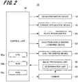
- FIG. 2 is a block diagram showing a configuration example of a control system of the three-dimensional PBF-AM apparatus according to the first embodiment of the present invention.
- a control unit 50 includes, for example, a central processing unit (CPU) 50a, a read only memory (ROM) 50b, and a random access memory (RAM) 50c (not shown), and the CPU 50a reads a program written in the ROM 50b into the RAM 50c and executes predetermined control processing, thereby integrally controlling the operation of the three-dimensional PBF-AM apparatus 10.
- CPU central processing unit
- ROM read only memory
- RAM random access memory
- the CPU 50a reads a program written in the ROM 50b into the RAM 50c and executes predetermined control processing, thereby integrally controlling the operation of the three-dimensional PBF-AM apparatus 10.
- an electron shield raising/lowering device 52, a shutter driving device 54, and an image processing unit 56 are connected to the control unit 50.
- the plate moving device 26 moves the build plate 22 based on a control command given from the control unit 50.
- the powder application device 16 applies the metal powder 32 onto the build plate 22 based on a control command given from the control unit 50.
- the operations of the hopper 16a, the powder dropping device 16b, and the squeegee 16c included in the powder application device 16 are controlled by the control unit 50.
- the electron shield raising/lowering device 52 raises and lowers the electron shield 30 based on a control command given from the control unit 50.
- the shutter driving device 54 is a device that opens and closes the shutter 44 described above.
- the shutter driving device 54 opens and closes the shutter 44 based on a control command given from the control unit 50. For example, the shutter driving device 54 suppresses contamination of the observation window by holding the shutter 44 in a closed state in the sintering step described later based on a control command given from the control unit 50.
- the image processing unit 56 takes in an image generated by the camera 42 and performs predetermined image processing on the captured image.
- the image processing unit 56 includes a determination unit 58 that determines the presence or absence of powder application failure when the powder application device 16 applies the metal powder 32.
- the determination unit 58 determines whether powder application failure has occurred using the image taken in from the camera 42.
- the image processing unit 56 includes, for example, an image processing processor. Specific processing contents performed by the image processing unit 56 and the determination unit 58 will be described later.
- the function of the image processing unit 56 may be realized by a CPU, a ROM, and a RAM constituting the control unit 50. That is, the image processing unit 56 can be configured integrally with the control unit 50.
- FIG. 3 is a flowchart showing a procedure of a processing operation of the three-dimensional PBF-AM apparatus according to the first embodiment of the present invention. The processing operation shown in this flowchart is performed under the control of the control unit 50.
- the manufacturing is started under the state described above.
- the beam irradiation device 14 operates based on a control command given from the control unit 50 to heat the build plate 22 (step S1).
- step S1 the beam irradiation device 14 irradiates the build plate 22 with the electron beam 15 through the opening portion 30a of the electron shield 30, and scans the build plate 22 with the electron beam 15.
- the build plate 22 is heated to a temperature at which the metal powder 32 is calcined.
- the plate moving device 26 operates based on a control command given from the control unit 50 to lower the build plate 22 by a predetermined amount (step S2).
- step S2 the plate moving device 26 lowers the inner base 24 by a predetermined amount so that the upper surface of the build plate 22 is slightly lower than the upper surface of the metal powder 32 spread on the build table 18. At this time, the build plate 22 lowers by a predetermined amount together with the inner base 24.
- the predetermined amount hereinafter, also referred to as " ⁇ Z"
- ⁇ Z corresponds to the thickness of one layer when the manufactured object 38 is built by laminating.
- the electron shield raising/lowering device 52 operates based on a control command given from the control unit 50 to raise the electron shield 30 (step S3).
- step S3 the electron shield raising/lowering device 52 raises the electron shield 30 to a position higher than the squeegee 16c so that the squeegee 16c does not come into contact with the electron shield 30 in the next step S4.
- the powder application device 16 operates based on a control command given from the control unit 50 to apply the metal powder 32 onto the build plate 22 to form the powder layer 32a (step S4).
- step S4 the powder application device 16 drops the metal powder 32 supplied from the hopper 16a to the powder dropping device 16b onto the build table 18 by the powder dropping device 16b, and then moves the squeegee 16c in the X direction to spread the metal powder 32 on the build plate 22. At this time, the metal powder 32 is spread on the build plate 22 with a thickness corresponding to ⁇ Z. Thus, the powder layer 32a is formed on the build plate 22. The excess metal powder 32 is recovered in the collection box 21.
- the electron shield raising/lowering device 52 operates based on a control command given from the control unit 50 to lower the electron shield 30 (step S5).
- step S5 the electron shield raising/lowering device 52 lowers the electron shield 30 so as to come into contact with the manufactured surface 32b of the metal powder 32.
- the metal powder 32 on the build plate 22 is exposed to the outside through the opening portion 30a of the electron shield 30. Further, the metal powder 32 present around the build plate 22 is covered by the mask portion 30b of the electron shield 30.
- the beam irradiation device 14 operates based on a control command given from the control unit 50 to preheat the powder layer 32a on the build plate 22 (step S6).
- the powder layer 32a is preheated in order to calcine the metal powder 32.
- the metal powder 32 can have conductivity. Therefore, powder scattering in the sintering step performed after the preheating step can be suppressed.
- the preheating performed before the sintering step is also referred to as powder-heat.
- step S6 the beam irradiation device 14 irradiates the metal powder 32 on the build plate 22 with the electron beam 15.
- the beam irradiation device 14 scans an area wider than a region for forming the manufactured object 38 (hereinafter, also referred to as a "manufacturing region") with the electron beam 15.
- a region for forming the manufactured object 38 hereinafter, also referred to as a "manufacturing region"
- reference numeral E1 denotes a non-calcined region where the non-calcined metal powder 32 is present
- reference numeral E2 denotes a calcined region where the calcined metal powder 32 is present.
- the beam irradiation device 14 operates based on a control command given from the control unit 50 to sinter the metal powder 32 by melting and solidification (step S7) .
- step S7 the metal powder 32 as a calcined body is sintered by melting and solidifying the metal powder 32 calcined as described above by irradiation with the electron beam 15.
- the beam irradiation device 14 specifies a manufacturing region based on two-dimensional data obtained by slicing three-dimensional CAD data of a target manufactured object 38 to a constant thickness (thickness corresponding to ⁇ Z), and scans the manufacturing region with the electron beam 15 to selectively melt the metal powder 32 on the build plate 22.
- the metal powder 32 melted by the irradiation of the electron beam 15 is solidified after the electron beam 15 passes.
- the manufactured object in the first layer is formed.
- the plate moving device 26 operates based on a control command given from the control unit 50 to lower the build plate 22 by a predetermined amount ( ⁇ Z) (step S8).
- step S8 the plate moving device 26 lowers the build plate 22 and the inner base 24 by ⁇ Z.
- the beam irradiation device 14 operates based on a control command given from the control unit 50 to preheat the powder layer 32a on the build plate 22 (step S9).
- the powder layer 32a that has been subjected to the sintering step in the previous layer is preheated.
- the preheating performed after the sintering step is also referred to as after-heating.
- step S9 the beam irradiation device 14 irradiates the powder layer 32a with the electron beam 15 through the opening portion 30a of the electron shield 30, and scans the powder layer 32a with the electron beam 15. As a result, the powder layer 32a exposed to the opening portion 30a is heated to a temperature at which the metal powder 32 is calcined.
- the electron shield raising/lowering device 52 operates based on a control command given from the control unit 50 to raise the electron shield 30 (step S10).
- step S10 the electron shield raising/lowering device 52 raises the electron shield 30 to a position higher than the squeegee 16c so that the squeegee 16c does not come into contact with the electron shield 30 in the next step S11.
- the powder application device 16 operates based on a control command given from the control unit 50 to apply the metal powder 32 onto the build plate 22 and form the powder layer 32a (step S11).
- step S11 the powder application device 16 operates similarly to step S4 described above.
- the metal powder 32 in the second layer is spread over the sintered body formed by the metal powder 32 in the first layer.
- the electron shield raising/lowering device 52 operates based on a control command given from the control unit 50 to lower the electron shield 30 (step S12).
- step S12 the electron shield raising/lowering device 52 operates similarly to step S5 described above.
- the beam irradiation device 14 operates based on a control command given from the control unit 50 to preheat the metal powder 32 forming the powder layer 32a in the second layer (step S13).
- the powder layer 32a is preheated in order to suppress powder scattering in the sintering step performed later.
- step S13 the beam irradiation device 14 operates similarly to step S6 described above. As a result, the metal powder 32 forming the powder layer 32a in the second layer is calcined.
- the beam irradiation device 14 operates based on a control command given from the control unit 50 to sinter the metal powder 32 forming the powder layer 32a in the second layer by melting and solidification (step S14).
- step S14 the beam irradiation device 14 operates similarly to step S7 described above.
- the manufactured object in the second layer is formed.
- control unit 50 confirms whether the manufacturing of the target manufactured object 38 is completed (step S15). When determining that the manufacturing of the manufactured object 38 is not completed, the control unit 50 returns to step S8 described above. As a result, the control unit 50 performs again the processes of steps S8 to S14 described above for each of the third and subsequent layers. When it is determined that the manufacturing of the manufactured object 38 is completed, the series of processing is terminated at that time.
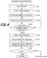
- FIG. 4 is a flowchart showing a processing procedure of the powder application step according to the first embodiment of the present invention. The processing shown in the flowchart is performed under the control of the control unit 50 and applied to step S11 in FIG. 3 .
- the powder dropping device 16b drops the metal powder 32 onto the build table 18 according to a control command from the control unit 50 (step S101).
- the amount of the metal powder 32 dropped by the powder dropping device 16b corresponds to the application amount necessary to form the powder layer 32a with a thickness of ⁇ Z.
- the image processing unit 56 starts taking in an image from the camera 42 according to a control command from the control unit 50 (step S102).
- the camera 42 continuously photographs the manufactured surface 32b of the powder layer 32a after the camera power is turned on under the control of the control unit 50.
- the image photographed by the camera 42 may be a still image or a moving image. In the case of a still image, an image of the camera 42 is taken into the image processing unit 56 at a predetermined frame rate.
- the squeegee 16c starts moving from the left end to the right end on the build table 18 shown in FIG. 1 according to a control command from the control unit 50 (step S103). At this time, the squeegee 16c moves while pushing the metal powder 32 with the blade 16d. The movement of the squeegee 16c is displayed in an image photographed by the camera 42.
- the camera 42 photographs the manufactured surface 32b of the powder layer 32a through the opening portion 30a of the electron shield 30. Therefore, the state of the squeegee 16c passing through the manufactured surface 32b so as to cross the opening portion 30a of the electron shield 30 is displayed in the image photographed by the camera 42. Furthermore, an image photographed by the camera 42 while the squeegee 16c is passing through the manufactured surface 32b is taken into the image processing unit 56.
- the determination unit 58 calculates ⁇ A for each pixel using the photographed image of the camera 42 obtained at a predetermined frame rate while the squeegee 16c is passing through the manufactured surface 32b (step S104).
- ⁇ A is a difference between a predicted feature value of an image immediately after the squeegee 16c passes and a feature value (measured feature value) of an image immediately after the squeegee 16c passes in a frame image representing the state of the manufactured surface 32b in time series.
- the feature value of the image may be any value as long as the value changes according to the temperature change of the manufactured surface 32b heated in the preheating step before the powder application step.
- the feature value of the image is at least one of intensity and saturation of the image.
- the feature value of the image is the intensity of the image
- the predicted feature value of the image described above is replaced with the predicted intensity of the image
- the feature value of the image is replaced with the intensity (measured intensity) of the image.
- the predicted intensity of the image is intensity predicted from the temporal change of the intensity of the image before the squeegee 16c passes.
- the time immediately after the squeegee 16c passes refers to a range of time in which a difference occurs in the feature value (intensity or saturation) of the image to the extent that the case where powder application failure of the metal powder 32 occurs and the case where powder application failure does not occur can be distinguished.
- the reason why the timing of confirming the difference between the predicted feature value and the measured feature value is limited to immediately after the squeegee 16c passes is as follows.
- the intensity of the image of the manufactured surface 32b decreases once, then gradually increases with the lapse of time, and then turns to a decreasing trend.
- the intensity of the image of the manufactured surface 32b uniformly and gradually decreases.
- the timing of confirming the difference between the predicted feature value and the measured feature value is limited to immediately after the squeegee 16c passes.
- the determination unit 58 obtains an approximate expression indicating the temporal change of the intensity based on the temporal change of the intensity of the image before the squeegee 16c passes, and determines the predicted intensity immediately after the squeegee 16c passes according to the obtained approximate expression.
- an approximate expression indicating the temporal change of the intensity based on the temporal change of the intensity of the image before the squeegee 16c passes.
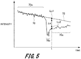
- FIG. 5 is a diagram for explaining the relationship between the measured intensity of the image and the approximate expression, and the vertical axis of FIG. 5 represents the intensity of the image and the horizontal axis represents time.
- a measured intensity 70 of the image indicates a change in intensity in an optional pixel 74a among a plurality of pixels constituting the image 74.
- the measured intensity 70 of the image is roughly divided into three periods on the time axis. Specifically, the measured intensity 70 is roughly divided into a measured intensity 70a obtained before the squeegee 16c passes through the pixel 74a as shown in FIG. 6A , a measured intensity 70b obtained while the squeegee 16c passes through the pixel 74a as shown in FIG. 6B , and a measured intensity 70c obtained after the squeegee 16c passes through the pixel 74a as shown in FIG. 6C .
- the reason why the measured intensity 70a gradually decreases is that the temperature of the manufactured surface 32b heated and red-heated in the preheating step before the powder application step gradually decreases with the lapse of time, and accordingly, the hue of the manufactured surface 32b gradually decreases.
- the reason why the measured intensity 70b rapidly decreases is that the squeegee 16c is present in front of the manufactured surface 32b as viewed from the camera 42, and the squeegee 16c is displayed more darkly than the manufactured surface 32b.
- the reason why the measured intensity 70c gradually increases is that the novel metal powder 32 covering the manufactured surface 32b by the passage of the squeegee 16c is gradually heated by the heat transferred from the manufactured surface 32b, and becomes reddish.
- the determination unit 58 obtains an approximate expression indicating a temporal change in the measured intensity 70a obtained before the squeegee 16c passes.
- the approximate expression 72 can be obtained by, for example, a least squares method.
- the approximate expression 72 can be expressed by a straight line indicating the inclination of the change in the measured intensity 70a shown in FIG. 5 or a line close to this straight line.
- the approximate expression 72 indicates a change in intensity predicted in a case where new metal powder 32 is not applied onto the manufactured surface 32b during and after the passage of the squeegee 16c.
- the determination unit 58 determines a predicted intensity Lv1 according to the approximate expression 72 obtained above. Assuming that a time (timing) immediately after the squeegee 16c passes is t, the predicted intensity Lv1 is obtained by inputting the time t into the approximate expression 72 and calculating the time t.
- the predicted intensity immediately after the squeegee 16c passes can be determined.
- the determination unit 58 acquires a measured intensity Lv2 obtained at the time t immediately after the squeegee 16c passes.
- the value of the intensity difference ⁇ A becomes a large value when the metal powder 32 is applied normally to the manufactured surface 32b by the passage of the squeegee 16c, and becomes a small value when the metal powder is not applied normally.
- the case where the metal powder 32 is applied normally refers to a case where new metal powder 32 is applied with a thickness corresponding to ⁇ Z on the manufactured surface 32b.
- the case where the metal powder 32 is not applied normally refers to a case where no new metal powder 32 is applied onto the manufactured surface 32b, or a case where the application thickness is insufficient as compared with ⁇ Z even if the new metal powder is applied.
- the intensity difference ⁇ A described above is calculated for each pixel constituting the image of the manufactured surface 32b photographed by the camera 42 during the movement of the squeegee 16c. Therefore, when the image of the manufactured surface 32b includes a total of M pixels, the determination unit 58 calculates a total of M intensity differences ⁇ A.
- the image processing unit 56 determines whether the squeegee 16c has completely passed through the manufactured surface 32b (step S105).
- the squeegee 16c completely passes through the manufactured surface 32b, the squeegee 16c is hidden behind the mask portion 30b of the electron shield 30 and cannot be seen. Therefore, the image processing unit 56 determines that the squeegee 16c has completely passed through the manufactured surface 32b when the squeegee 16c is no longer displayed in the image taken in from the camera 42.
- the process returns to step S104 described above.
- the calculation of the intensity difference ⁇ A is continued until the squeegee 16c completely passes through the manufactured surface 32b. Therefore, the value of the intensity difference ⁇ A is obtained for all the pixels constituting the image of the manufactured surface 32b.
- step S105 when it is determined as YES in step S105, the process proceeds to step S106.
- step S106 the image processing unit 56 finishes taking in the image from the camera 42.
- the movement of the squeegee 16c to the movement end point is detected by, for example, an end point detection sensor (not shown)
- the movement of the squeegee 16c is ended according to a control command from the control unit 50 based on the detection result (step S107).
- the movement end point of the squeegee 16c is set at the right end of the build table 18 shown in FIG. 1 .
- the squeegee 16c moves to the movement end point and then returns to the movement start point while leveling the upper surface of the powder layer 32a. That is, the squeegee 16c reciprocates on the build table 18.
- the determination unit 58 compares the magnitude relationship between the intensity difference ⁇ A calculated as described above and a preset first threshold SH1 for each pixel, and calculates a total number B of pixels satisfying the condition of ⁇ A ⁇ SH1 based on the comparison result (step S108).
- the first threshold SH1 is a threshold set in the determination unit 58 in order to discriminate between a pixel to which the metal powder 32 has been applied normally and a pixel to which the metal powder 32 has not been applied normally.
- the pixel satisfying the condition of ⁇ A ⁇ SH1 is a pixel for which it is determined that the metal powder 32 has not been applied normally, that is, a pixel suspected of having powder application failure of the metal powder 32 (hereinafter, also referred to as an "abnormal pixel").
- a pixel satisfying the condition of ⁇ A > SH1 is a pixel for which it is determined that the metal powder 32 has been applied normally (hereinafter, also referred to as a "normal pixel").
- the determination unit 58 compares the magnitude relationship between the total number B of abnormal pixels calculated as described above and a preset second threshold SH2 (step S109).
- the second threshold SH2 is a threshold set to determine whether powder application failure of a level that may lead to a defect of the manufactured object has occurred in the metal powder 32 (powder layer 32a) newly applied on the build plate 22 by the movement of the squeegee 16c.
- the defect of the manufactured object caused by the powder application failure may be a dimensional accuracy error exceeding an allowable value.
- the second threshold SH2 is set to a value sufficiently smaller than M when the image of the manufactured surface 32b photographed by the camera 42 includes a total of M pixels.
- the second threshold SH2 can be optionally set or changed according to the level of the defect allowed in the manufactured object.
- step S109 when the total number B of abnormal pixels exceeds the second threshold SH2, the determination unit 58 determines that powder application failure of the metal powder 32 has occurred (determined as YES in step S109). In addition, in step S109, when the total number B of abnormal pixels is equal to or less than the second threshold SH2, the determination unit 58 determines that powder application failure of the metal powder 32 has not occurred (determined as NO in step S109).
- step S109 the process proceeds to step S9 in FIG. 3 .
- the control unit 50 performs the first preheating step S9 and the powder application step S11 again for the current layer manufacturing.
- step S12 in FIG. 3 the control unit 50 performs the second preheating step S13 and the sintering step S14 without performing the first preheating step S9 and the powder application step S11 again for the current layer manufacturing.
- control unit 50 may control the powder application device 16 so as to increase the application amount of the metal powder 32 by the powder application device 16 (in other words, the dropping amount of the metal powder 32 by the powder dropping device 16b) more than that before the powder application step is performed again.
- the control unit 50 may control the powder application device 16 so as to increase the application amount of the metal powder 32 by the powder application device 16 (in other words, the dropping amount of the metal powder 32 by the powder dropping device 16b) more than that before the powder application step is performed again.
- the three-dimensional PBF-AM apparatus 10 includes the determination unit 58 that determines whether powder application failure of the metal powder 32 has occurred using the image photographed by the camera 42 while the squeegee 16c is moving on the manufactured surface 32b. As a result, the occurrence of powder application failure of the metal powder 32 can be automatically detected.
- the determination unit 58 determines that powder application failure has occurred in the powder application step, manufacturing work after the occurrence of powder application failure can be suitably continued by operating the three-dimensional PBF-AM apparatus 10 in a mode different from the case where powder application failure has not occurred. As a result, deterioration of the dimensional accuracy of the manufactured object due to powder application failure can be suppressed.
- the determination unit 58 obtains the difference ( ⁇ A) between the predicted intensity Lv1 immediately after the squeegee 16c passes and the measured intensity Lv2 immediately after the squeegee 16c passes, which is predicted from the temporal change in the intensity of the image before the squeegee 16c passes, using the image photographed by the camera 42 while the squeegee 16c passes through the manufactured surface 32b, and determines whether powder application failure of the metal powder 32 has occurred based on the obtained difference.
- the data ( ⁇ A) for determining the presence or absence of powder application failure can be acquired in real time. Therefore, the occurrence of powder application failure can be detected early.
- the control unit 50 when the determination unit 58 determines that powder application failure has occurred, the control unit 50 performs the first preheating step and the powder application step again before performing the second preheating step and the sintering step for the current layer manufacturing.
- the laminated state of the powder layer 32a can be restored to a favorable state by performing the first preheating step and the powder application step again thereafter. Therefore, it is possible to suppress the occurrence of defects such as dimensional accuracy deviation in the manufactured object. In addition, generation of voids due to insufficient melting can be suppressed.
- the thickness of the powder layer 32a becomes partially or entirely thinner than ⁇ Z due to the occurrence of powder application failure in the powder application step, if the manufacturing work is continued as usual without taking any measures, the thickness of the powder layer 32a may become partially or entirely thicker than ⁇ Z when the powder application step is performed for the next layer. In such a case, the amount of heat stored in the powder layer 32a as the previous layer in the first preheating step (after-heating step) may not be spread to the entire powder layer 32a forming the next layer, and the calcination may not be sufficiently promoted.
- the metal powder 32 is irradiated with the electron beam 15 while the powder particles of the metal powder 32 have high electric resistance, the neutralization of the charges of the powder is not promoted, and there is a high possibility that a phenomenon in which the powder is scattered by repulsion between the charges, that is, smoke occurs.
- smoke occurs, powder particles scattered in the vacuum chamber 12 are scattered in a wide range, which may contaminate the inside of the vacuum chamber 12 or damage components arranged in the vacuum chamber 12.
- the metal powder 32 can be spread so that the thickness of the powder layer 32a is entirely uniform ( ⁇ Z) by performing the first preheating step and the powder application step again. Therefore, the calcination of the next layer can be sufficiently promoted, and the occurrence of smoke in the second preheating step of the next layer can be suppressed. Therefore, contamination or breakage in the vacuum chamber 12 can be suppressed.
- the total number B of abnormal pixels is calculated, and it is determined that powder application failure of the metal powder 32 has occurred when the calculated total number B exceeds the second threshold SH2.
- the present invention is not limited thereto, and the total area of abnormal pixels may be calculated instead of the total number B of abnormalities. Then, when the calculated total area of the abnormal pixels exceeds the second threshold, it may be determined that powder application failure of the metal powder 32 has occurred.
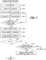
- FIG. 7 is a flowchart showing a processing procedure of the powder application step according to a second embodiment of the present invention.
- step S101 to step S109 is the same, but the flow of processing after it is determined as YES in step S109 is different.
- step S109 the process proceeds to step S110.
- step S110 the control unit 50 confirms whether the determination unit 58 has continuously determined that powder application failure has occurred twice or more in a row in step S109.
- step S9 the control unit 50 performs the first preheating step S9 and the powder application step S11 again for the current layer manufacturing.
- step S110 when it is determined as NO in step S110, that is, when the number of times that the determination unit 58 determines that powder application failure has occurred is 1 (first time), the control unit 50 proceeds to step S111.
- step S111 the control unit 50 reserves the condition to be applied to the next layer manufacturing, and then returns to step S12 in FIG. 3 .
- the condition to be applied to the next layer manufacturing is reserved with a content different from a condition to be applied when there is no powder scattering (hereinafter, also referred to as a "normal condition").
- the control unit 50 performs a reservation for extending the execution time of the first preheating step S9, a reservation for increasing the application amount of the powder material in the powder application step S11, and a reservation for enhancing the energy applied to the powder layer 32a in the sintering step S14.
- the execution time of the first preheating step S9 is a time from the start to the end of the irradiation (scanning) of the electron beam 15 in the first preheating step S9.
- the execution time of the first preheating step S9 is extended, the irradiation time of the electron beam 15 becomes longer as compared with the case where the normal condition is applied, and the temperature of the powder layer 32a becomes higher accordingly. Therefore, instead of the reservation for extending the execution time of the first preheating step S9, a reservation for setting the heating target temperature of the first preheating step S9 higher than the normal condition may be made.
- the application amount of the powder material is defined by the dropping amount of the metal powder 32 dropped from the powder dropping device 16b in the powder application step S11. Therefore, the control unit 50 makes a reservation for increasing the dropping amount of the metal powder 32 by the powder dropping device 16b more than under the normal condition.
- step S111 the control unit 50 may perform all of the reservation for extending the execution time of the first preheating step S9, the reservation for increasing the heating target temperature of the first preheating step S9, the reservation for increasing the application amount of the powder material in the powder application step S11, and the reservation for enhancing the energy applied to the powder layer 32a in the sintering step S14, or may perform any three, any two, or any one of the reservations.
- the condition reserved in step S111 may be applied not only to the next layer but also continuously applied to two or more layers including the next layer.
- control unit 50 when returning to step S12 after reserving the condition to be applied to the next layer manufacturing in step S111, the control unit 50 performs the second preheating step S13 and the sintering step S14 without performing the first preheating step S9 and the powder application step S11 again for the current layer manufacturing. Then, when the processes of steps S8 to S14 are performed on the next layer, the control unit 50 applies the execution time and/or the heating target temperature reserved in step S111 described above in the first preheating step S9, applies the application amount of the powder material (metal powder 32) reserved in step S111 described above in the powder application step S11, and applies the energy amount reserved in step S111 described above in the sintering step S109.
- N is an integer larger than 2
- N is an integer larger than 2
- the control unit 50 reserves the condition to be applied to the next layer manufacturing with a content different from the condition to be applied when powder application failure of the powder material has not occurred, and then performs the second preheating step S13 and the sintering step S14 for the current layer manufacturing. Then, for the next layer manufacturing, the control unit 50 performs the plate lowering step S8, the first preheating step S9, the powder application step S11, the second preheating step S13, and the sintering step S14 according to the reserved condition.
- the manufacturing throughput can be improved as compared with the first embodiment described above.
- the reason is as follows.
- the first preheating step S9 and the powder application step S11 are performed again for the current layer manufacturing. Performing the step as described above leads to a decrease in manufacturing throughput while an effect of suppressing the occurrence of defects by recovering the laminated state of the powder layer 32a is obtained.
- the second preheating step S13 and the sintering step S14 are performed for the current layer manufacturing after the condition to be applied to the next layer manufacturing is reserved. Therefore, it is possible to suppress a decrease in manufacturing throughput caused when the steps are performed again.
- the next layer manufacturing by carrying out the next layer manufacturing according to the reserved condition, it is possible to appropriately cope with the change in the thickness of the powder layer 32a accompanying the powder application failure. More specifically, when powder application failure occurs in the powder application step S11 in the current layer manufacturing, the thickness of the powder layer 32a becomes partially or entirely thin. Therefore, when the powder application step is performed for the next layer manufacturing, the metal powder 32 is applied thickly so as to compensate for the thinness of the previous layer. For example, in a case where the thickness of a powder layer 32a-1 is partially thinner than ⁇ Z in the current layer manufacturing as shown in FIG.
- a reservation for extending the execution time of the first preheating step S9, a reservation for increasing the application amount of the powder material in the powder application step S11, and a reservation for enhancing the energy applied to the powder layer 32a in the sintering step S14 are performed. Therefore, insufficient heating in the first preheating step S9, insufficient application in the powder application step S11, and insufficient energy in the sintering step S14 can be avoided. Therefore, it is possible to appropriately cope with the change in the thickness of the powder layer 32a accompanying the powder application failure. Furthermore, the laminating of the manufactured object can be restored to a favorable state without performing the step again.
- FIG. 9 is a flowchart showing a processing procedure of the powder application step according to a third embodiment of the present invention. The processing shown in this flowchart is performed under the control of the control unit 50, and applied to step S11 and/or step S4 in FIG. 3 .
- Step S201 is performed similarly to step S101 described above.
- Step S202 is performed similarly to step S103 described above.
- step S203 determines whether the squeegee 16c has completely passed through the manufactured surface 32b (step S203). Step S203 is performed similarly to step S105 described above. When it is determined as NO in step S203, the process waits until the squeegee 16c completely passes through the manufactured surface 32b, and when it is determined as YES in step S203, the process proceeds to step S204.
- step S204 the image processing unit 56 takes in an image from the camera 42. As a result, an image showing the state of the powder layer 32a immediately after the squeegee 16c passes through the manufactured surface 32b is obtained. The reason why the camera image immediately after the squeegee 16c passes through the manufactured surface 32b is used will be described later.
- Step S205 is performed similarly to step S107 described above.
- the squeegee 16c moves to the movement end point and then returns to the movement start point while leveling the upper surface of the powder layer 32a.
- the determination unit 58 determines whether powder application failure of the metal powder 32 has occurred by the following processing using the image taken in by the image processing unit 56 in step S204 described above.
- the determination unit 58 binarizes the image taken in by the image processing unit 56 (step S206).
- the image is binarized as a pretreatment for the determination unit 58 to determine whether powder application failure of the metal powder 32 has occurred. Details will be described below.
- the temperature of the manufactured surface 32b decreases. Therefore, the image of the manufactured surface 32b photographed by the camera 42 is slightly darker than before the metal powder 32 of the next layer is spread.
- the image of the portion is brighter than that in a case where the metal powder is applied normally. Therefore, the image of the manufactured surface 32b after the application of the metal powder 32 is finished by the squeegee 16c is taken from the camera 42 and binarized, so that the intensity distribution of the image can be grasped by the black-and-white image.
- the black-and-white image is an image including a combination of a white region and a black region.
- a portion where the metal powder 32 is applied normally is a dark image, and a portion where the metal powder 32 is not applied normally is displayed as a bright image.
- the determination unit 58 determines whether powder application failure of the metal powder 32 has occurred based on the intensity distribution of the image grasped from the black-and-white image after binarization. Specifically, in step S207, when the ratio of the white region in the black-and-white image after binarization exceeds the predetermined value, the determination unit 58 determines that powder application failure has occurred (determined as YES in step S207), and otherwise (determined as NO in step S207), the determination unit 58 determines that powder application failure has not occurred. When it is determined as YES in step S207, the process proceeds to step S9 in FIG. 3 , and when it is determined as NO in step S207, the process proceeds to step S12 in FIG. 3 .
- the manufactured surface 32b of the lower layer (previous layer) as a base is covered with the newly applied metal powder 32, and thus the intensity of the image of the manufactured surface 32b decreases.
- the intensity of the image of the manufactured surface 32b gradually increases with the lapse of time thereafter. This is because the temperature of the newly applied metal powder 32 is raised by the heat transferred from the manufactured surface 32b being the base, and the image of the manufactured surface 32b gradually becomes brighter.
- the time immediately after the squeegee 16c passes through the manufactured surface 32b refers to a range of time in which a difference occurs in the intensity distribution of the image to the extent that the case where powder application failure of the metal powder 32 occurs and the case where powder application failure does not occur can be distinguished.
- the three-dimensional PBF-AM apparatus 10 includes the determination unit 58 that determines whether powder application failure of the metal powder 32 has occurred using the image photographed by the camera 42 immediately after the squeegee 16c passes through the manufactured surface 32b. As a result, effects similar to those of the first embodiment can be obtained.
- step S207 when the determination unit 58 detects the occurrence of powder application failure (when it is determined as YES in step S207), the process proceeds to step S110 shown in FIG. 7 , whereby effects similar to those of the second embodiment can be obtained.
- the method of binarizing the image photographed by the camera 42 immediately after the squeegee 16c passes through the manufactured surface 32b and determining the presence or absence of powder application failure of the metal powder 32 based on the black-and-white image obtained by the binarizing is not limited to the above method, and various modifications as described below can be made, for example.
- the metal powder 32 dropped by the powder dropping device 16b is spread by the movement of the squeegee 16c
- the metal powder 32 may be heated at a relatively early stage after the powder spreading and start to be red-heated depending on the set temperature of the preheating step performed before the spread or the type of the metal powder 32 to be used. Therefore, for example, when the squeegee 16c is moved from the left to the right in FIG. 1 , the metal powder 32 starts to be red-heated first from the left side close to the movement start point of the squeegee 16c. Therefore, in the black-and-white image obtained by binarizing the photographed image of the camera 42, as shown in FIG.
- Subtraction of the portion of the white region 80 substantially means that the white region 80 is regarded as a black region. Which part of the white region 80 to be subtracted is to be specified in advance by an experiment or the like.
- FIG. 10B when a white region 82 accompanying the powder application failure and the above-described white region 80 are present in the black-and-white image after binarization, it is possible to exclude the influence of the white region 80, extract only the white region 82, and determine the presence or absence of the occurrence of powder application failure based on the ratio of the white region 82. Further, in the black-and-white image shown in FIG.
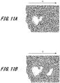
- FIG. 11A is a black-and-white image obtained by binarizing a camera image in a case where powder application failure does not occur
- FIG. 11B is a black-and-white image obtained by binarizing a camera image in a case where powder application failure occurs.
- the outer shape of the manufactured surface 32b is indicated by a white circle for convenience of drawing notation. The same applies to FIGS. 13A to 13C described later.
- the determination unit 58 may determine that powder application failure of the metal powder 32 has occurred when the white region appearing in the image on the downstream side in the squeegee movement direction is wider than the white region appearing in the image on the upstream side in the squeegee movement direction. Specifically, as shown in FIG.
- a black-and-white image 84 after binarization is divided into an image 84a on the upstream side in the squeegee movement direction and an image 84b on the downstream side in the squeegee movement direction with the center position in the X direction as a boundary. Then, when a white region 86 appearing in the image 84b on the downstream side in the squeegee movement direction is wider than the white region (not shown) appearing in the image 84a on the upstream side in the squeegee movement direction, the determination unit 58 determines that powder application failure of the metal powder 32 has occurred. For reference, FIG.
- FIG. 13A is a black-and-white image obtained by binarizing a camera image in a case where powder application failure does not occur
- FIGS. 13B and 13C are both black-and-white images obtained by binarizing a camera image in a case where powder application failure occurs.
- a white region 88 widely appears in the image portion located on the upstream side in the squeegee movement direction. This is because the metal powder 32 starts to be red-heated at a relatively early stage after the powder spreading as described above.
- the white region 88 appearing in the image on the upstream side in the squeegee movement direction may be subtracted or ignored, the widths of the white region appearing in the image on the downstream side in the squeegee movement direction and the white region appearing in the image on the upstream side in the squeegee movement direction may be compared, and the presence or absence of powder application failure may be determined based on the comparison result.
- the position to be divided into the image 84a and the image 84b is not limited to the center position in the X direction, and may be a position deviated slightly upstream or downstream of the center position in the X direction.
- the manufactured surface 32b is irradiated with light from the illuminating light source, in a case where a region that looks always bright from the camera 42 (in other words, an image portion that always becomes a white region by binarization) due to the positional relationship between the illuminating light source and the camera 42, or the like is present, it is possible to accurately determine the presence or absence of the occurrence of powder application failure by subtracting or ignoring the region.
- whether powder application failure of the metal powder 32 has occurred is determined based on the intensity distribution indicated by the black-and-white image including the white region and the black region, that is, the two-gradation image obtained by binarizing the image photographed by the camera 42, but the present invention is not limited thereto.
- the image photographed by the camera 42 may be converted into a gray scale multi-gradation image, and whether powder application failure of the metal powder 32 has occurred may be determined based on the intensity distribution represented by the multi-gradation image.
- whether powder application failure of the metal powder 32 has occurred is determined based on the intensity distribution of the image photographed by the camera 42 immediately after the squeegee 16c passes through the manufactured surface 32b.
- the present invention is not limited thereto, and the red saturation distribution of the image may be adopted instead of the intensity distribution of the image. The reason is as follows.
- the manufactured surface 32b of the powder layer 32a is red-heated and becomes red.
- the reddishness of the portion to which the metal powder 32 is applied normally is weakened and the blackish hue is obtained, that is, the saturation is lowered
- the color of the manufactured surface 32b of the base (red-heated state) is raised and the red hue is obtained, that is, the saturation is increased. Therefore, even when the saturation distribution is adopted instead of the intensity distribution, the presence or absence of the occurrence of powder application failure can be determined.
Landscapes
- Engineering & Computer Science (AREA)
- Chemical & Material Sciences (AREA)
- Materials Engineering (AREA)
- Manufacturing & Machinery (AREA)
- Analytical Chemistry (AREA)
- Automation & Control Theory (AREA)
- Physics & Mathematics (AREA)
- Plasma & Fusion (AREA)
- Powder Metallurgy (AREA)
Abstract
Description
- The present invention relates to a three-dimensional powder bed fusion additive manufacturing apparatus and a three-dimensional powder bed fusion additive manufacturing method.
- In recent years, a three-dimensional powder bed fusion additive manufacturing (PBF-AM) apparatus is known which irradiates a powder material spread in layers on a build plate with a beam to melt and solidify the powder material, and sequentially stacks the solidified layers by moving the build plate to form a three-dimensional manufactured object. This type of three-dimensional PBF-AM apparatus is described in, for example,
Patent Literature 1. - Patent Literature 1:
JP 2015-167125 A - In the three-dimensional PBF-AM apparatus described in
Patent Literature 1, when a powder material is applied onto a build plate, the powder material is not uniformly applied, and powder application failure such as a partial thickness reduction of a powder layer may occur. The occurrence of the powder application failure causes a decrease in dimensional accuracy of the manufactured object. - The present invention has been made to solve the above problems, and an object thereof is to provide a technique capable of detecting powder application failure of a powder material and suppressing a decrease in dimensional accuracy of a manufactured object due to the powder application failure.
- A three-dimensional powder bed fusion additive manufacturing apparatus according to the present invention includes: a build plate; a plate moving device that moves the build plate in an up-down direction; a powder application device that applies a powder material onto the build plate to form a powder layer, the powder application device including a squeegee that moves on the build plate to spread the powder material; a beam irradiation device that irradiates the build plate or the powder layer with a beam; a control unit that controls the plate moving device, the powder application device, and the beam irradiation device to form a manufactured object for one layer through a plate lowering step, a first preheating step, a powder application step, a second preheating step, and a sintering step, and to form a three-dimensional manufactured object by laminating the manufactured object for one layer; a camera that photographs a manufactured surface of the powder layer; and a determination unit that determines whether powder application failure of the powder material has occurred using an image photographed by the camera while or immediately after the squeegee passes through the manufactured surface.
- A three-dimensional powder bed fusion additive manufacturing method according to the present invention includes: a first preheating step of preheating a build plate or a powder layer on the build plate; a powder application step of applying a powder material onto the build plate by moving a squeegee in a horizontal direction on the build plate after the first preheating step to form a powder layer; a second preheating step of preheating the powder layer on the build plate after the powder application step; and a sintering step of sintering the powder material forming the powder layer after the second preheating step, in which, in the powder application step, it is determined whether powder application failure of the powder material has occurred using an image of the manufactured surface photographed by a camera while or immediately after the squeegee passes through the manufactured surface of the powder layer.
- According to the present invention, it is possible to detect powder application failure of a powder material and suppress a decrease in dimensional accuracy of a manufactured object due to the powder application failure.
-
-
FIG. 1 is a side view schematically showing a configuration of a three-dimensional powder bed fusion additive manufacturing (PBF-AM) apparatus according to a first embodiment of the present invention; -
FIG. 2 is a block diagram showing a configuration example of a control system of the three-dimensional PBF-AM apparatus according to the first embodiment of the present invention; -
FIG. 3 is a flowchart showing a procedure of a basic processing operation of the three-dimensional PBF-AM apparatus according to the first embodiment of the present invention; -
FIG. 4 is a flowchart showing a procedure of a processing operation of the three-dimensional PBF-AM apparatus according to the first embodiment of the present invention; -
FIG. 5 is a diagram for explaining a relationship between measured intensity of an image and an approximate expression; -
FIGS. 6A to 6C are schematic diagrams showing an example of an image obtained by photographing a manufactured surface with a camera; -
FIG. 7 is a flowchart showing a processing procedure of a powder application step according to a second embodiment of the present invention; -
FIGS. 8A and 8B are schematic diagrams showing a change in thickness of a powder layer accompanying powder application failure; -
FIG. 9 is a flowchart showing a processing procedure of a powder application step according to a third embodiment of the present invention; -
FIGS. 10A to 10B are schematic diagrams showing an example of a black-and-white image obtained by binarizing an image photographed by a camera; -
FIGS. 11A and 11B are diagrams showing a first specific example of a black-and-white image obtained by binarizing an image photographed by a camera; -
FIG. 12 is a schematic diagram showing a state in which a black-and-white image obtained by binarizing an image photographed by a camera is divided into an image on an upstream side in a squeegee movement direction and an image on a downstream side in the squeegee movement direction; and -
FIGS. 13A to 13C are diagrams showing a second specific example of a black-and-white image obtained by binarizing an image photographed by a camera. - Hereinafter, embodiments of the present invention will be described in detail with reference to the drawings. In the present specification and the drawings, elements having substantially the same function or configuration are denoted by the same reference numerals, and redundant description is omitted.
-
FIG. 1 is a side view schematically showing a configuration of a three-dimensional powder bed fusion additive manufacturing (PBF-AM) apparatus according to a first embodiment of the present invention. In the following description, in order to clarify the shape, positional relationship, and the like of each part of the three-dimensional PBF-AM apparatus, the right-left direction inFIG. 1 is referred to as an X direction, the depth direction inFIG. 1 is referred to as a Y direction, and the up-down direction inFIG. 1 is referred to as a Z direction. The X direction, the Y direction, and the Z direction are directions orthogonal to each other. The X direction and the Y direction are parallel to the horizontal direction, and the Z direction is parallel to the vertical direction. - As shown in
FIG. 1 , the three-dimensional PBF-AM apparatus 10 includes avacuum chamber 12, abeam irradiation device 14, apowder application device 16, a build table 18, abuild box 20, acollection box 21, abuild plate 22, aninner base 24, aplate moving device 26, aradiation shield cover 28, anelectron shield 30, acamera 42, and ashutter 44. - The
vacuum chamber 12 is a chamber for creating a vacuum state by evacuating air in the chamber by a vacuum pump (not shown). - The
beam irradiation device 14 is a device that irradiates thebuild plate 22 or apowder layer 32a with anelectron beam 15. Theelectron beam 15 is an example of a beam. Thepowder layer 32a is a layer formed by applyingmetal powder 32 to thebuild plate 22. Although not shown, thebeam irradiation device 14 includes an electron gun that is a generation source of theelectron beam 15, a focusing lens that focuses the electron beam generated by the electron gun, and a deflection lens that deflects theelectron beam 15 focused by the focusing lens. The focusing lens is configured using a focusing coil, and focuses theelectron beam 15 by a magnetic field generated by the focusing coil. The deflection lens is configured using a deflection coil, and deflects theelectron beam 15 by a magnetic field generated by the deflection coil. - The
powder application device 16 is a device that applies themetal powder 32 onto thebuild plate 22 to form thepowder layer 32a as an example of a powder material as a raw material of a manufacturedobject 38. Thepowder application device 16 includes ahopper 16a, apowder dropping device 16b, and asqueegee 16c. Thehopper 16a is a chamber for storing metal powder. The powder droppingdevice 16b is a device that drops the metal powder stored in thehopper 16a onto the build table 18. Thesqueegee 16c moves in the horizontal direction on thebuild plate 22 to spread themetal powder 32. Thesqueegee 16c is an elongated member long in the Y direction, and includes ablade 16d for spreading powder. Thesqueegee 16c spreads themetal powder 32 on the build table 18 while pushing themetal powder 32 dropped by the powder droppingdevice 16b with theblade 16d. Thesqueegee 16c is provided to be movable in the X direction in order to spread themetal powder 32 over the entire surface of the build table 18. - The build table 18 is horizontally arranged inside the
vacuum chamber 12. The build table 18 is arranged below thepowder application device 16. A central portion of the build table 18 is opened. The opening shape of the build table 18 is a circle in plan view or a square in plan view (for example, a quadrangle in plan view). - The
build box 20 is a box that forms a space for manufacturing. An upper end portion of thebuild box 20 is connected to an opening edge of the build table 18. A lower end portion of thebuild box 20 is connected to a bottom wall of thevacuum chamber 12. - The
collection box 21 is a box that recovers themetal powder 32 supplied more than necessary among themetal powder 32 supplied onto the build table 18 by thepowder application device 16. - The
build plate 22 is a plate for forming the manufacturedobject 38 using themetal powder 32. The manufacturedobject 38 is formed by being laminated on thebuild plate 22. Thebuild plate 22 is formed in a circle in plan view or a square in plan view in accordance with the opening shape of the build table 18. Thebuild plate 22 is connected (grounded) to theinner base 24 by aground wire 34 so as not to be in an electrically floating state. Theinner base 24 is held at a ground (GND) potential. Themetal powder 32 is spread over thebuild plate 22 and theinner base 24. - The
inner base 24 is provided to be movable in the up-down direction (Z direction). Thebuild plate 22 moves in the up-down direction integrally with theinner base 24. Theinner base 24 has a larger outer dimension than thebuild plate 22. Theinner base 24 slides in the up-down direction along the inner surface of thebuild box 20. Aseal member 36 is attached to an outer peripheral portion of theinner base 24. Theseal member 36 is a member that maintains slidability and sealability between the outer peripheral portion of theinner base 24 and the inner surface of thebuild box 20. Theseal member 36 is made of a material having heat resistance and elasticity. - The
plate moving device 26 is a device that moves thebuild plate 22 and theinner base 24 in the up-down direction. Theplate moving device 26 includes ashaft 26a and adrive mechanism unit 26b. Theshaft 26a is connected to the lower surface of theinner base 24. Thedrive mechanism unit 26b includes a motor and a power transmission mechanism (not shown), and drives the power transmission mechanism using the motor as a drive source to move thebuild plate 22 and theinner base 24 integrally with theshaft 26a in the up-down direction. The power transmission mechanism includes, for example, a rack and pinion mechanism, a ball screw mechanism, and the like. - The
radiation shield cover 28 is arranged between thebuild plate 22 and thebeam irradiation device 14 in the Z direction. Theradiation shield cover 28 is made of metal such as stainless steel. Theradiation shield cover 28 shields radiation heat generated when themetal powder 32 is irradiated with theelectron beam 15 by thebeam irradiation device 14. When themetal powder 32 is irradiated with theelectron beam 15 in order to sinter themetal powder 32, themetal powder 32 is melted. At this time, when heat radiated from a manufacturedsurface 32b of thepowder layer 32a, that is, radiant heat is widely diffused into thevacuum chamber 12, thermal efficiency is deteriorated. On the other hand, when theradiation shield cover 28 is arranged above thebuild plate 22, the heat radiated from the manufacturedsurface 32b is shielded by theradiation shield cover 28, and the shielded heat is reflected by theradiation shield cover 28 and returned to thebuild plate 22 side. Therefore, the heat generated by the irradiation of theelectron beam 15 can be efficiently used. The manufacturedsurface 32b corresponds to the upper surface of thepowder layer 32a formed by spreading themetal powder 32 on thebuild plate 22. - In addition, the
radiation shield cover 28 has a function of suppressing adhesion (vapor deposition) of an evaporation material generated when themetal powder 32 is irradiated with theelectron beam 15 to the inner wall of thevacuum chamber 12. When themetal powder 32 is irradiated with theelectron beam 15, a part of the melted metal becomes an atomized evaporation material and rises from the manufacturedsurface 32b. Theradiation shield cover 28 is arranged so as to cover the space above the manufacturedsurface 32b so that the evaporation material does not diffuse into thevacuum chamber 12. - The
electron shield 30 has anopening portion 30a and amask portion 30b. In forming the manufacturedobject 38, theelectron shield 30 is arranged to cover the upper surface of themetal powder 32, that is, the manufacturedsurface 32b. At this time, theopening portion 30a exposes themetal powder 32 spread on thebuild plate 22, and themask portion 30b shields themetal powder 32 positioned outside theopening portion 30a. The shape of theopening portion 30a is set in accordance with the shape of thebuild plate 22. For example, if thebuild plate 22 is circular in plan view, the shape in plan view of theopening portion 30a is set to be circular accordingly, and if thebuild plate 22 is angular in plan view, the shape in plan view of theopening portion 30a is set to be angular accordingly. In the present embodiment, as an example, it is assumed that the shape of theopening portion 30a in plan view is circular. - The
electron shield 30 is arranged below theradiation shield cover 28. Theopening portion 30a and themask portion 30b of theelectron shield 30 are arranged between thebuild plate 22 and theradiation shield cover 28 in the Z direction. Theelectron shield 30 includes a surroundingportion 30c. The surroundingportion 30c is arranged so as to surround the space above theopening portion 30a. A part (upper portion) of the surroundingportion 30c overlaps theradiation shield cover 28 in the Z direction. The surroundingportion 30c has a function of shielding radiant heat generated from the manufacturedsurface 32b and a function of suppressing diffusion of an evaporation material generated from the manufacturedsurface 32b. That is, the surroundingportion 30c has the same function as theradiation shield cover 28. - The
electron shield 30 is made of metal having a melting point higher than that of themetal powder 32 used as a raw material of the manufacturedobject 38. Theelectron shield 30 is made of a material having low reactivity with themetal powder 32. As a constituent material of theelectron shield 30, for example, titanium can be exemplified. Theelectron shield 30 may be made of metal of the same material as themetal powder 32 to be used. Theelectron shield 30 is electrically grounded to GND. In a preheating step before a sintering step described later, when themetal powder 32 is calcined by irradiation with theelectron beam 15, theelectron shield 30 performs an electrical shielding function to suppress the occurrence of powder scattering to a small scale. - The
camera 42 is a camera capable of photographing the manufacturedsurface 32b of thepowder layer 32a. Thecamera 42 is arranged to be shifted in position in the Y direction from thebeam irradiation device 14 so as not to interfere with the position of thebeam irradiation device 14. Thecamera 42 is preferably a visible light camera such as a digital video camera. Thecamera 42 photographs the manufacturedsurface 32b of thepowder layer 32a to generate an image (image data) of thepowder layer 32a. Further, thecamera 42 photographs the manufacturedsurface 32b through theopening portion 30a of theelectron shield 30. Therefore, when the shape of theopening portion 30a of theelectron shield 30 in plan view is circular, the image of the manufacturedsurface 32b photographed by thecamera 42 is a circular image. The photographing by thecamera 42 is performed in a state where illumination light emitted from an illumination light source (not shown) included in the three-dimensional PBF-AM apparatus 10 is applied to the manufacturedsurface 32b of thepowder layer 32a. - In the present embodiment, when the
powder layer 32a is irradiated with theelectron beam 15 from thebeam irradiation device 14, theelectron shield 30 is arranged so as to cover the manufacturedsurface 32b of thepowder layer 32a. Therefore, the manufacturedsurface 32b substantially means the manufacturedsurface 32b visible from thecamera 42 through theopening portion 30a of theelectron shield 30. In the case of the three-dimensional PBF-AM apparatus 10 not including theelectron shield 30, the upper surface of themetal powder 32 calcined by irradiation with theelectron beam 15 corresponds to the manufacturedsurface 32b. - The
shutter 44 protects an observation window so that the evaporation material generated from the manufacturedsurface 32b when themetal powder 32 is melted by the irradiation of theelectron beam 15 does not adhere to the observation window. The photographing of the manufacturedsurface 32b by thecamera 42 is performed in a state where theshutter 44 is opened. In addition, the step in which the evaporation material is likely to be generated and the step in which the amount of the evaporation material generated is large are performed in a state where theshutter 44 is closed. The observation window is attached to the vacuum chamber. The camera is set to the outside of the observation window (atmosphere side), and photographing of the manufactured surface by the camera is performed through the observation window. -
FIG. 2 is a block diagram showing a configuration example of a control system of the three-dimensional PBF-AM apparatus according to the first embodiment of the present invention. - In
FIG. 2 , acontrol unit 50 includes, for example, a central processing unit (CPU) 50a, a read only memory (ROM) 50b, and a random access memory (RAM) 50c (not shown), and theCPU 50a reads a program written in theROM 50b into theRAM 50c and executes predetermined control processing, thereby integrally controlling the operation of the three-dimensional PBF-AM apparatus 10. In addition to thebeam irradiation device 14, thepowder application device 16, theplate moving device 26, and thecamera 42 described above, an electron shield raising/loweringdevice 52, ashutter driving device 54, and animage processing unit 56 are connected to thecontrol unit 50. - The
plate moving device 26 moves thebuild plate 22 based on a control command given from thecontrol unit 50. Thepowder application device 16 applies themetal powder 32 onto thebuild plate 22 based on a control command given from thecontrol unit 50. The operations of thehopper 16a, thepowder dropping device 16b, and thesqueegee 16c included in thepowder application device 16 are controlled by thecontrol unit 50. The electron shield raising/loweringdevice 52 raises and lowers theelectron shield 30 based on a control command given from thecontrol unit 50. Theshutter driving device 54 is a device that opens and closes theshutter 44 described above. Theshutter driving device 54 opens and closes theshutter 44 based on a control command given from thecontrol unit 50. For example, theshutter driving device 54 suppresses contamination of the observation window by holding theshutter 44 in a closed state in the sintering step described later based on a control command given from thecontrol unit 50. - The
image processing unit 56 takes in an image generated by thecamera 42 and performs predetermined image processing on the captured image. Theimage processing unit 56 includes adetermination unit 58 that determines the presence or absence of powder application failure when thepowder application device 16 applies themetal powder 32. Thedetermination unit 58 determines whether powder application failure has occurred using the image taken in from thecamera 42. Theimage processing unit 56 includes, for example, an image processing processor. Specific processing contents performed by theimage processing unit 56 and thedetermination unit 58 will be described later. The function of theimage processing unit 56 may be realized by a CPU, a ROM, and a RAM constituting thecontrol unit 50. That is, theimage processing unit 56 can be configured integrally with thecontrol unit 50. -
FIG. 3 is a flowchart showing a procedure of a processing operation of the three-dimensional PBF-AM apparatus according to the first embodiment of the present invention. The processing operation shown in this flowchart is performed under the control of thecontrol unit 50. - First, in a state before the manufacturing is started, three sides of the
build plate 22 are covered with themetal powder 32 except for the upper surface of thebuild plate 22. Furthermore, the upper surface of thebuild plate 22 is arranged at substantially the same height as the upper surface of themetal powder 32 spread on the build table 18. On the other hand, theelectron shield 30 is lowered to the upper surface of thebuild plate 22. In this case, themetal powder 32 present around thebuild plate 22 is covered by themask portion 30b of theelectron shield 30. Themask portion 30b is in contact with themetal powder 32. The manufacturing is started under the state described above. - First, the
beam irradiation device 14 operates based on a control command given from thecontrol unit 50 to heat the build plate 22 (step S1). - In step S1, the
beam irradiation device 14 irradiates thebuild plate 22 with theelectron beam 15 through theopening portion 30a of theelectron shield 30, and scans thebuild plate 22 with theelectron beam 15. Thus, thebuild plate 22 is heated to a temperature at which themetal powder 32 is calcined. - Next, the
plate moving device 26 operates based on a control command given from thecontrol unit 50 to lower thebuild plate 22 by a predetermined amount (step S2). - In step S2, the
plate moving device 26 lowers theinner base 24 by a predetermined amount so that the upper surface of thebuild plate 22 is slightly lower than the upper surface of themetal powder 32 spread on the build table 18. At this time, thebuild plate 22 lowers by a predetermined amount together with theinner base 24. The predetermined amount (hereinafter, also referred to as "ΔZ") described here corresponds to the thickness of one layer when the manufacturedobject 38 is built by laminating. - Next, the electron shield raising/lowering
device 52 operates based on a control command given from thecontrol unit 50 to raise the electron shield 30 (step S3). - In step S3, the electron shield raising/lowering
device 52 raises theelectron shield 30 to a position higher than thesqueegee 16c so that thesqueegee 16c does not come into contact with theelectron shield 30 in the next step S4. - Next, the
powder application device 16 operates based on a control command given from thecontrol unit 50 to apply themetal powder 32 onto thebuild plate 22 to form thepowder layer 32a (step S4). - In step S4, the
powder application device 16 drops themetal powder 32 supplied from thehopper 16a to thepowder dropping device 16b onto the build table 18 by thepowder dropping device 16b, and then moves thesqueegee 16c in the X direction to spread themetal powder 32 on thebuild plate 22. At this time, themetal powder 32 is spread on thebuild plate 22 with a thickness corresponding to ΔZ. Thus, thepowder layer 32a is formed on thebuild plate 22. Theexcess metal powder 32 is recovered in thecollection box 21. - Next, the electron shield raising/lowering
device 52 operates based on a control command given from thecontrol unit 50 to lower the electron shield 30 (step S5). - In step S5, the electron shield raising/lowering
device 52 lowers theelectron shield 30 so as to come into contact with the manufacturedsurface 32b of themetal powder 32. Thus, themetal powder 32 on thebuild plate 22 is exposed to the outside through theopening portion 30a of theelectron shield 30. Further, themetal powder 32 present around thebuild plate 22 is covered by themask portion 30b of theelectron shield 30. - Next, the
beam irradiation device 14 operates based on a control command given from thecontrol unit 50 to preheat thepowder layer 32a on the build plate 22 (step S6). In the preheating step S6, thepowder layer 32a is preheated in order to calcine themetal powder 32. When themetal powder 32 is calcined, themetal powder 32 can have conductivity. Therefore, powder scattering in the sintering step performed after the preheating step can be suppressed. The preheating performed before the sintering step is also referred to as powder-heat. - In step S6, the
beam irradiation device 14 irradiates themetal powder 32 on thebuild plate 22 with theelectron beam 15. At this time, by covering themetal powder 32 with theelectron shield 30 and radiating theelectron beam 15, the occurrence of powder scattering in the preheating step S6 is suppressed by an electrical shielding effect of theelectron shield 30. Furthermore, thebeam irradiation device 14 scans an area wider than a region for forming the manufactured object 38 (hereinafter, also referred to as a "manufacturing region") with theelectron beam 15. Thus, themetal powder 32 present in the manufacturing region and themetal powder 32 present around the manufacturing region are both calcined. - In
FIG. 1 , reference numeral E1 denotes a non-calcined region where thenon-calcined metal powder 32 is present, and reference numeral E2 denotes a calcined region where thecalcined metal powder 32 is present. - Next, the
beam irradiation device 14 operates based on a control command given from thecontrol unit 50 to sinter themetal powder 32 by melting and solidification (step S7) . - In step S7, the
metal powder 32 as a calcined body is sintered by melting and solidifying themetal powder 32 calcined as described above by irradiation with theelectron beam 15. In step S7, thebeam irradiation device 14 specifies a manufacturing region based on two-dimensional data obtained by slicing three-dimensional CAD data of a target manufacturedobject 38 to a constant thickness (thickness corresponding to ΔZ), and scans the manufacturing region with theelectron beam 15 to selectively melt themetal powder 32 on thebuild plate 22. Themetal powder 32 melted by the irradiation of theelectron beam 15 is solidified after theelectron beam 15 passes. Thus, the manufactured object in the first layer is formed. - Next, the
plate moving device 26 operates based on a control command given from thecontrol unit 50 to lower thebuild plate 22 by a predetermined amount (ΔZ) (step S8). - In step S8, the
plate moving device 26 lowers thebuild plate 22 and theinner base 24 by ΔZ. - Subsequently, the
beam irradiation device 14 operates based on a control command given from thecontrol unit 50 to preheat thepowder layer 32a on the build plate 22 (step S9). In the first preheating step S9, as a preparation for spreading themetal powder 32 in the next layer, thepowder layer 32a that has been subjected to the sintering step in the previous layer is preheated. The preheating performed after the sintering step is also referred to as after-heating. - In step S9, the
beam irradiation device 14 irradiates thepowder layer 32a with theelectron beam 15 through theopening portion 30a of theelectron shield 30, and scans thepowder layer 32a with theelectron beam 15. As a result, thepowder layer 32a exposed to theopening portion 30a is heated to a temperature at which themetal powder 32 is calcined. - Next, the electron shield raising/lowering
device 52 operates based on a control command given from thecontrol unit 50 to raise the electron shield 30 (step S10). - In step S10, the electron shield raising/lowering
device 52 raises theelectron shield 30 to a position higher than thesqueegee 16c so that thesqueegee 16c does not come into contact with theelectron shield 30 in the next step S11. - Next, the
powder application device 16 operates based on a control command given from thecontrol unit 50 to apply themetal powder 32 onto thebuild plate 22 and form thepowder layer 32a (step S11). - In step S11, the
powder application device 16 operates similarly to step S4 described above. Thus, on thebuild plate 22, themetal powder 32 in the second layer is spread over the sintered body formed by themetal powder 32 in the first layer. - Next, the electron shield raising/lowering
device 52 operates based on a control command given from thecontrol unit 50 to lower the electron shield 30 (step S12). - In step S12, the electron shield raising/lowering
device 52 operates similarly to step S5 described above. - Next, the
beam irradiation device 14 operates based on a control command given from thecontrol unit 50 to preheat themetal powder 32 forming thepowder layer 32a in the second layer (step S13). In the second preheating step S13, thepowder layer 32a is preheated in order to suppress powder scattering in the sintering step performed later. - In step S13, the
beam irradiation device 14 operates similarly to step S6 described above. As a result, themetal powder 32 forming thepowder layer 32a in the second layer is calcined. - Next, the
beam irradiation device 14 operates based on a control command given from thecontrol unit 50 to sinter themetal powder 32 forming thepowder layer 32a in the second layer by melting and solidification (step S14). - In step S14, the
beam irradiation device 14 operates similarly to step S7 described above. Thus, the manufactured object in the second layer is formed. - Next, the
control unit 50 confirms whether the manufacturing of the target manufacturedobject 38 is completed (step S15). When determining that the manufacturing of the manufacturedobject 38 is not completed, thecontrol unit 50 returns to step S8 described above. As a result, thecontrol unit 50 performs again the processes of steps S8 to S14 described above for each of the third and subsequent layers. When it is determined that the manufacturing of the manufacturedobject 38 is completed, the series of processing is terminated at that time. -
FIG. 4 is a flowchart showing a processing procedure of the powder application step according to the first embodiment of the present invention. The processing shown in the flowchart is performed under the control of thecontrol unit 50 and applied to step S11 inFIG. 3 . - First, under the arrangement state shown in
FIG. 1 , thepowder dropping device 16b drops themetal powder 32 onto the build table 18 according to a control command from the control unit 50 (step S101). At this time, the amount of themetal powder 32 dropped by thepowder dropping device 16b corresponds to the application amount necessary to form thepowder layer 32a with a thickness of ΔZ. - Next, the
image processing unit 56 starts taking in an image from thecamera 42 according to a control command from the control unit 50 (step S102). Thecamera 42 continuously photographs the manufacturedsurface 32b of thepowder layer 32a after the camera power is turned on under the control of thecontrol unit 50. The image photographed by thecamera 42 may be a still image or a moving image. In the case of a still image, an image of thecamera 42 is taken into theimage processing unit 56 at a predetermined frame rate. - Next, the
squeegee 16c starts moving from the left end to the right end on the build table 18 shown inFIG. 1 according to a control command from the control unit 50 (step S103). At this time, thesqueegee 16c moves while pushing themetal powder 32 with theblade 16d. The movement of thesqueegee 16c is displayed in an image photographed by thecamera 42. In the present embodiment, thecamera 42 photographs the manufacturedsurface 32b of thepowder layer 32a through theopening portion 30a of theelectron shield 30. Therefore, the state of thesqueegee 16c passing through the manufacturedsurface 32b so as to cross theopening portion 30a of theelectron shield 30 is displayed in the image photographed by thecamera 42. Furthermore, an image photographed by thecamera 42 while thesqueegee 16c is passing through the manufacturedsurface 32b is taken into theimage processing unit 56. - Next, the
determination unit 58 calculates ΔA for each pixel using the photographed image of thecamera 42 obtained at a predetermined frame rate while thesqueegee 16c is passing through the manufacturedsurface 32b (step S104). ΔA is a difference between a predicted feature value of an image immediately after thesqueegee 16c passes and a feature value (measured feature value) of an image immediately after thesqueegee 16c passes in a frame image representing the state of the manufacturedsurface 32b in time series. The feature value of the image may be any value as long as the value changes according to the temperature change of the manufacturedsurface 32b heated in the preheating step before the powder application step. As a preferred example, the feature value of the image is at least one of intensity and saturation of the image. In the present embodiment, a case where the feature value of the image is the intensity of the image will be described as an example. In that case, the predicted feature value of the image described above is replaced with the predicted intensity of the image, and the feature value of the image is replaced with the intensity (measured intensity) of the image. - The predicted intensity of the image is intensity predicted from the temporal change of the intensity of the image before the
squeegee 16c passes. The time immediately after thesqueegee 16c passes refers to a range of time in which a difference occurs in the feature value (intensity or saturation) of the image to the extent that the case where powder application failure of themetal powder 32 occurs and the case where powder application failure does not occur can be distinguished. The reason why the timing of confirming the difference between the predicted feature value and the measured feature value is limited to immediately after thesqueegee 16c passes is as follows. - First, when the
metal powder 32 is normally applied by passage of thesqueegee 16c, the intensity of the image of the manufacturedsurface 32b decreases once, then gradually increases with the lapse of time, and then turns to a decreasing trend. On the other hand, when themetal powder 32 is not applied normally, the intensity of the image of the manufacturedsurface 32b uniformly and gradually decreases. When the time longer than the time immediately after thesqueegee 16c passes elapses, there is almost no difference in the intensity of the image between the case where powder application failure of themetal powder 32 occurs and the case where powder application failure does not occur. That is, when a certain period of time or more elapses after thesqueegee 16c passes, it becomes difficult to discriminate between a case where powder application failure of themetal powder 32 occurs and a case where powder application failure does not occur. Therefore, the timing of confirming the difference between the predicted feature value and the measured feature value is limited to immediately after thesqueegee 16c passes. - The
determination unit 58 obtains an approximate expression indicating the temporal change of the intensity based on the temporal change of the intensity of the image before thesqueegee 16c passes, and determines the predicted intensity immediately after thesqueegee 16c passes according to the obtained approximate expression. Hereinafter, a method of determining the predicted intensity will be described in detail. -
FIG. 5 is a diagram for explaining the relationship between the measured intensity of the image and the approximate expression, and the vertical axis ofFIG. 5 represents the intensity of the image and the horizontal axis represents time. - Assuming that the image obtained by photographing the manufactured
surface 32b by thecamera 42 is animage 74 as shown inFIGS. 6A to 6C , a measuredintensity 70 of the image indicates a change in intensity in anoptional pixel 74a among a plurality of pixels constituting theimage 74. The measuredintensity 70 of the image is roughly divided into three periods on the time axis. Specifically, the measuredintensity 70 is roughly divided into a measuredintensity 70a obtained before thesqueegee 16c passes through thepixel 74a as shown inFIG. 6A , a measuredintensity 70b obtained while thesqueegee 16c passes through thepixel 74a as shown inFIG. 6B , and a measuredintensity 70c obtained after thesqueegee 16c passes through thepixel 74a as shown inFIG. 6C . - The reason why the measured
intensity 70a gradually decreases is that the temperature of the manufacturedsurface 32b heated and red-heated in the preheating step before the powder application step gradually decreases with the lapse of time, and accordingly, the hue of the manufacturedsurface 32b gradually decreases. The reason why the measuredintensity 70b rapidly decreases is that thesqueegee 16c is present in front of the manufacturedsurface 32b as viewed from thecamera 42, and thesqueegee 16c is displayed more darkly than the manufacturedsurface 32b. The reason why the measuredintensity 70c gradually increases is that thenovel metal powder 32 covering the manufacturedsurface 32b by the passage of thesqueegee 16c is gradually heated by the heat transferred from the manufacturedsurface 32b, and becomes reddish. - The
determination unit 58 obtains an approximate expression indicating a temporal change in the measuredintensity 70a obtained before thesqueegee 16c passes. Theapproximate expression 72 can be obtained by, for example, a least squares method. In this case, theapproximate expression 72 can be expressed by a straight line indicating the inclination of the change in the measuredintensity 70a shown inFIG. 5 or a line close to this straight line. Furthermore, theapproximate expression 72 indicates a change in intensity predicted in a case wherenew metal powder 32 is not applied onto the manufacturedsurface 32b during and after the passage of thesqueegee 16c. - Next, the
determination unit 58 determines a predicted intensity Lv1 according to theapproximate expression 72 obtained above. Assuming that a time (timing) immediately after thesqueegee 16c passes is t, the predicted intensity Lv1 is obtained by inputting the time t into theapproximate expression 72 and calculating the time t. - By the above method, the predicted intensity immediately after the
squeegee 16c passes can be determined. - Next, the
determination unit 58 acquires a measured intensity Lv2 obtained at the time t immediately after thesqueegee 16c passes. - Next, the
determination unit 58 calculates the difference between the predicted intensity Lv1 and the measured intensity Lv2 described above as ΔA. That is, thedetermination unit 58 obtains the intensity difference ΔA by a calculation formula of ΔA = Lv1 - Lv2. The value of the intensity difference ΔA becomes a large value when themetal powder 32 is applied normally to the manufacturedsurface 32b by the passage of thesqueegee 16c, and becomes a small value when the metal powder is not applied normally. The case where themetal powder 32 is applied normally refers to a case wherenew metal powder 32 is applied with a thickness corresponding to ΔZ on the manufacturedsurface 32b. On the other hand, the case where themetal powder 32 is not applied normally refers to a case where nonew metal powder 32 is applied onto the manufacturedsurface 32b, or a case where the application thickness is insufficient as compared with ΔZ even if the new metal powder is applied. - The intensity difference ΔA described above is calculated for each pixel constituting the image of the manufactured
surface 32b photographed by thecamera 42 during the movement of thesqueegee 16c. Therefore, when the image of the manufacturedsurface 32b includes a total of M pixels, thedetermination unit 58 calculates a total of M intensity differences ΔA. - Next, the
image processing unit 56 determines whether thesqueegee 16c has completely passed through the manufacturedsurface 32b (step S105). When thesqueegee 16c completely passes through the manufacturedsurface 32b, thesqueegee 16c is hidden behind themask portion 30b of theelectron shield 30 and cannot be seen. Therefore, theimage processing unit 56 determines that thesqueegee 16c has completely passed through the manufacturedsurface 32b when thesqueegee 16c is no longer displayed in the image taken in from thecamera 42. When it is determined as NO in step S105, the process returns to step S104 described above. Thus, the calculation of the intensity difference ΔA is continued until thesqueegee 16c completely passes through the manufacturedsurface 32b. Therefore, the value of the intensity difference ΔA is obtained for all the pixels constituting the image of the manufacturedsurface 32b. - On the other hand, when it is determined as YES in step S105, the process proceeds to step S106. In step S106, the
image processing unit 56 finishes taking in the image from thecamera 42. - Thereafter, when the movement of the
squeegee 16c to the movement end point is detected by, for example, an end point detection sensor (not shown), the movement of thesqueegee 16c is ended according to a control command from thecontrol unit 50 based on the detection result (step S107). The movement end point of thesqueegee 16c is set at the right end of the build table 18 shown inFIG. 1 . Although not shown in the flowchart ofFIG. 4 , thesqueegee 16c moves to the movement end point and then returns to the movement start point while leveling the upper surface of thepowder layer 32a. That is, thesqueegee 16c reciprocates on the build table 18. - Next, the
determination unit 58 compares the magnitude relationship between the intensity difference ΔA calculated as described above and a preset first threshold SH1 for each pixel, and calculates a total number B of pixels satisfying the condition of ΔA ≤ SH1 based on the comparison result (step S108). The first threshold SH1 is a threshold set in thedetermination unit 58 in order to discriminate between a pixel to which themetal powder 32 has been applied normally and a pixel to which themetal powder 32 has not been applied normally. The pixel satisfying the condition of ΔA ≤ SH1 is a pixel for which it is determined that themetal powder 32 has not been applied normally, that is, a pixel suspected of having powder application failure of the metal powder 32 (hereinafter, also referred to as an "abnormal pixel"). In addition, a pixel satisfying the condition of ΔA > SH1 is a pixel for which it is determined that themetal powder 32 has been applied normally (hereinafter, also referred to as a "normal pixel"). - Next, the
determination unit 58 compares the magnitude relationship between the total number B of abnormal pixels calculated as described above and a preset second threshold SH2 (step S109). The second threshold SH2 is a threshold set to determine whether powder application failure of a level that may lead to a defect of the manufactured object has occurred in the metal powder 32 (powder layer 32a) newly applied on thebuild plate 22 by the movement of thesqueegee 16c. The defect of the manufactured object caused by the powder application failure may be a dimensional accuracy error exceeding an allowable value. The second threshold SH2 is set to a value sufficiently smaller than M when the image of the manufacturedsurface 32b photographed by thecamera 42 includes a total of M pixels. The second threshold SH2 can be optionally set or changed according to the level of the defect allowed in the manufactured object. - In step S109, when the total number B of abnormal pixels exceeds the second threshold SH2, the
determination unit 58 determines that powder application failure of themetal powder 32 has occurred (determined as YES in step S109). In addition, in step S109, when the total number B of abnormal pixels is equal to or less than the second threshold SH2, thedetermination unit 58 determines that powder application failure of themetal powder 32 has not occurred (determined as NO in step S109). - When it is determined as YES in step S109, the process proceeds to step S9 in
FIG. 3 . In this case, thecontrol unit 50 performs the first preheating step S9 and the powder application step S11 again for the current layer manufacturing. When it is determined as NO in step S109, the process proceeds to step S12 inFIG. 3 . In this case, thecontrol unit 50 performs the second preheating step S13 and the sintering step S14 without performing the first preheating step S9 and the powder application step S11 again for the current layer manufacturing. - The flowchart shown in
FIG. 4 can be applied not only to step S11 inFIG. 3 but also to step S4. In addition, in the case of performing the powder application step again, thecontrol unit 50 may control thepowder application device 16 so as to increase the application amount of themetal powder 32 by the powder application device 16 (in other words, the dropping amount of themetal powder 32 by thepowder dropping device 16b) more than that before the powder application step is performed again. As a result, it is possible to suppress the occurrence of powder application failure due to the shortage of the application amount of themetal powder 32 in the powder application step after it is performed again. - As described above, the three-dimensional PBF-
AM apparatus 10 according to the first embodiment of the present invention includes thedetermination unit 58 that determines whether powder application failure of themetal powder 32 has occurred using the image photographed by thecamera 42 while thesqueegee 16c is moving on the manufacturedsurface 32b. As a result, the occurrence of powder application failure of themetal powder 32 can be automatically detected. When thedetermination unit 58 determines that powder application failure has occurred in the powder application step, manufacturing work after the occurrence of powder application failure can be suitably continued by operating the three-dimensional PBF-AM apparatus 10 in a mode different from the case where powder application failure has not occurred. As a result, deterioration of the dimensional accuracy of the manufactured object due to powder application failure can be suppressed. - Furthermore, in the first embodiment of the present invention, the
determination unit 58 obtains the difference (ΔA) between the predicted intensity Lv1 immediately after thesqueegee 16c passes and the measured intensity Lv2 immediately after thesqueegee 16c passes, which is predicted from the temporal change in the intensity of the image before thesqueegee 16c passes, using the image photographed by thecamera 42 while thesqueegee 16c passes through the manufacturedsurface 32b, and determines whether powder application failure of themetal powder 32 has occurred based on the obtained difference. As a result, in parallel with the movement of thesqueegee 16c in the powder application step, the data (ΔA) for determining the presence or absence of powder application failure can be acquired in real time. Therefore, the occurrence of powder application failure can be detected early. - In the first embodiment of the present invention, when the
determination unit 58 determines that powder application failure has occurred, thecontrol unit 50 performs the first preheating step and the powder application step again before performing the second preheating step and the sintering step for the current layer manufacturing. As a result, even when powder application failure of themetal powder 32 occurs in the first powder application step, the laminated state of thepowder layer 32a can be restored to a favorable state by performing the first preheating step and the powder application step again thereafter. Therefore, it is possible to suppress the occurrence of defects such as dimensional accuracy deviation in the manufactured object. In addition, generation of voids due to insufficient melting can be suppressed. - Further, according to the first embodiment of the present invention, it is possible to suppress contamination or breakage in the
vacuum chamber 12. The reason is as follows. - When the thickness of the
powder layer 32a becomes partially or entirely thinner than ΔZ due to the occurrence of powder application failure in the powder application step, if the manufacturing work is continued as usual without taking any measures, the thickness of thepowder layer 32a may become partially or entirely thicker than ΔZ when the powder application step is performed for the next layer. In such a case, the amount of heat stored in thepowder layer 32a as the previous layer in the first preheating step (after-heating step) may not be spread to theentire powder layer 32a forming the next layer, and the calcination may not be sufficiently promoted. As a result, in the second preheating step (powder-heat step), since themetal powder 32 is irradiated with theelectron beam 15 while the powder particles of themetal powder 32 have high electric resistance, the neutralization of the charges of the powder is not promoted, and there is a high possibility that a phenomenon in which the powder is scattered by repulsion between the charges, that is, smoke occurs. When smoke occurs, powder particles scattered in thevacuum chamber 12 are scattered in a wide range, which may contaminate the inside of thevacuum chamber 12 or damage components arranged in thevacuum chamber 12. - On the other hand, in the first embodiment of the present invention, even if the thickness of the
powder layer 32a is partially or entirely reduced due to occurrence of powder application failure, themetal powder 32 can be spread so that the thickness of thepowder layer 32a is entirely uniform (ΔZ) by performing the first preheating step and the powder application step again. Therefore, the calcination of the next layer can be sufficiently promoted, and the occurrence of smoke in the second preheating step of the next layer can be suppressed. Therefore, contamination or breakage in thevacuum chamber 12 can be suppressed. - In the first embodiment, the total number B of abnormal pixels is calculated, and it is determined that powder application failure of the
metal powder 32 has occurred when the calculated total number B exceeds the second threshold SH2. However, the present invention is not limited thereto, and the total area of abnormal pixels may be calculated instead of the total number B of abnormalities. Then, when the calculated total area of the abnormal pixels exceeds the second threshold, it may be determined that powder application failure of themetal powder 32 has occurred. -
FIG. 7 is a flowchart showing a processing procedure of the powder application step according to a second embodiment of the present invention. - As shown in
FIG. 7 , in the second embodiment of the present invention, as compared with the processing procedure of the above-described first embodiment (seeFIG. 4 ), the flow of processing from step S101 to step S109 is the same, but the flow of processing after it is determined as YES in step S109 is different. - Specifically, when it is determined as YES in step S109, the process proceeds to step S110. In step S110, the
control unit 50 confirms whether thedetermination unit 58 has continuously determined that powder application failure has occurred twice or more in a row in step S109. When it is determined as YES in step S110, thecontrol unit 50 proceeds to step S9 inFIG. 3 . In this case, thecontrol unit 50 performs the first preheating step S9 and the powder application step S11 again for the current layer manufacturing. - On the other hand, when it is determined as NO in step S110, that is, when the number of times that the
determination unit 58 determines that powder application failure has occurred is 1 (first time), thecontrol unit 50 proceeds to step S111. - Next, in step S111, the
control unit 50 reserves the condition to be applied to the next layer manufacturing, and then returns to step S12 inFIG. 3 . The condition to be applied to the next layer manufacturing is reserved with a content different from a condition to be applied when there is no powder scattering (hereinafter, also referred to as a "normal condition"). Specifically, thecontrol unit 50 performs a reservation for extending the execution time of the first preheating step S9, a reservation for increasing the application amount of the powder material in the powder application step S11, and a reservation for enhancing the energy applied to thepowder layer 32a in the sintering step S14. The execution time of the first preheating step S9 is a time from the start to the end of the irradiation (scanning) of theelectron beam 15 in the first preheating step S9. When the execution time of the first preheating step S9 is extended, the irradiation time of theelectron beam 15 becomes longer as compared with the case where the normal condition is applied, and the temperature of thepowder layer 32a becomes higher accordingly. Therefore, instead of the reservation for extending the execution time of the first preheating step S9, a reservation for setting the heating target temperature of the first preheating step S9 higher than the normal condition may be made. The application amount of the powder material is defined by the dropping amount of themetal powder 32 dropped from thepowder dropping device 16b in the powder application step S11. Therefore, thecontrol unit 50 makes a reservation for increasing the dropping amount of themetal powder 32 by thepowder dropping device 16b more than under the normal condition. - As a method for enhancing the energy applied to the
powder layer 32a in the present sintering step S14, for example, the following methods (a), (b), and (c) can be considered. - (a) The beam current of the
electron beam 15 with which thepowder layer 32a is irradiated in the sintering step S14 is made larger than that under the normal condition. - (b) The scanning speed of the
electron beam 15 with which thepowder layer 32a is irradiated in the sintering step S14 is made lower than that under the normal condition. - (c) The interval between the scanning lines is made narrower (denser) than in the normal condition.
- In step S111, the
control unit 50 may perform all of the reservation for extending the execution time of the first preheating step S9, the reservation for increasing the heating target temperature of the first preheating step S9, the reservation for increasing the application amount of the powder material in the powder application step S11, and the reservation for enhancing the energy applied to thepowder layer 32a in the sintering step S14, or may perform any three, any two, or any one of the reservations. In addition, the condition reserved in step S111 may be applied not only to the next layer but also continuously applied to two or more layers including the next layer. - As described above, when returning to step S12 after reserving the condition to be applied to the next layer manufacturing in step S111, the
control unit 50 performs the second preheating step S13 and the sintering step S14 without performing the first preheating step S9 and the powder application step S11 again for the current layer manufacturing. Then, when the processes of steps S8 to S14 are performed on the next layer, thecontrol unit 50 applies the execution time and/or the heating target temperature reserved in step S111 described above in the first preheating step S9, applies the application amount of the powder material (metal powder 32) reserved in step S111 described above in the powder application step S11, and applies the energy amount reserved in step S111 described above in the sintering step S109. - Although not shown, when the number of times of YES determination in step S109 for the same layer reaches a predetermined number of times N (N is an integer larger than 2), there is a possibility that an abnormality that cannot be recovered even if the powder application step is performed again has occurred in the three-dimensional PBF-
AM apparatus 10, for example, the remaining amount of the powder in thehopper 16a has become empty. In that case, it is preferable to stop the operation of the three-dimensional PBF-AM apparatus 10 for device maintenance. The same applies to the first embodiment described above. - As described above, in the second embodiment of the present invention, when the
determination unit 58 determines that powder application failure of the powder material has occurred, thecontrol unit 50 reserves the condition to be applied to the next layer manufacturing with a content different from the condition to be applied when powder application failure of the powder material has not occurred, and then performs the second preheating step S13 and the sintering step S14 for the current layer manufacturing. Then, for the next layer manufacturing, thecontrol unit 50 performs the plate lowering step S8, the first preheating step S9, the powder application step S11, the second preheating step S13, and the sintering step S14 according to the reserved condition. - Thus, the manufacturing throughput can be improved as compared with the first embodiment described above. The reason is as follows.
- First, in the first embodiment described above, when the
determination unit 58 determines that powder application failure of the powder material has occurred, the first preheating step S9 and the powder application step S11 are performed again for the current layer manufacturing. Performing the step as described above leads to a decrease in manufacturing throughput while an effect of suppressing the occurrence of defects by recovering the laminated state of thepowder layer 32a is obtained. On the other hand, in the second embodiment, when thedetermination unit 58 determines that powder application failure of the powder material has occurred, the second preheating step S13 and the sintering step S14 are performed for the current layer manufacturing after the condition to be applied to the next layer manufacturing is reserved. Therefore, it is possible to suppress a decrease in manufacturing throughput caused when the steps are performed again. - Furthermore, by carrying out the next layer manufacturing according to the reserved condition, it is possible to appropriately cope with the change in the thickness of the
powder layer 32a accompanying the powder application failure. More specifically, when powder application failure occurs in the powder application step S11 in the current layer manufacturing, the thickness of thepowder layer 32a becomes partially or entirely thin. Therefore, when the powder application step is performed for the next layer manufacturing, themetal powder 32 is applied thickly so as to compensate for the thinness of the previous layer. For example, in a case where the thickness of apowder layer 32a-1 is partially thinner than ΔZ in the current layer manufacturing as shown inFIG. 8A , when apowder layer 32a-2 being the next layer is formed on thepowder layer 32a, the thickness of a manufacturedsurface 32b-2 is partially thicker than ΔZ as shown inFIG. 8B . In such a case, when manufacturing is performed with the same content as the normal condition, insufficient heating occurs in the first preheating step S9, insufficient application amount occurs in the powder application step S11, or energy shortage occurs in the sintering step S14. In the second embodiment, as the reservation for the condition to be applied to the next layer manufacturing, a reservation for extending the execution time of the first preheating step S9, a reservation for increasing the application amount of the powder material in the powder application step S11, and a reservation for enhancing the energy applied to thepowder layer 32a in the sintering step S14 are performed. Therefore, insufficient heating in the first preheating step S9, insufficient application in the powder application step S11, and insufficient energy in the sintering step S14 can be avoided. Therefore, it is possible to appropriately cope with the change in the thickness of thepowder layer 32a accompanying the powder application failure. Furthermore, the laminating of the manufactured object can be restored to a favorable state without performing the step again. -
FIG. 9 is a flowchart showing a processing procedure of the powder application step according to a third embodiment of the present invention. The processing shown in this flowchart is performed under the control of thecontrol unit 50, and applied to step S11 and/or step S4 inFIG. 3 . - First, under the arrangement state shown in
FIG. 1 , thepowder dropping device 16b drops themetal powder 32 onto the build table 18 according to a control command from the control unit 50 (step S201). Step S201 is performed similarly to step S101 described above. - Next, the
squeegee 16c starts moving from the left end to the right end on the build table 18 shown inFIG. 1 according to a control command from the control unit 50 (step S202). Step S202 is performed similarly to step S103 described above. - Next, the
image processing unit 56 determines whether thesqueegee 16c has completely passed through the manufacturedsurface 32b (step S203). Step S203 is performed similarly to step S105 described above. When it is determined as NO in step S203, the process waits until thesqueegee 16c completely passes through the manufacturedsurface 32b, and when it is determined as YES in step S203, the process proceeds to step S204. In step S204, theimage processing unit 56 takes in an image from thecamera 42. As a result, an image showing the state of thepowder layer 32a immediately after thesqueegee 16c passes through the manufacturedsurface 32b is obtained. The reason why the camera image immediately after thesqueegee 16c passes through the manufacturedsurface 32b is used will be described later. - Thereafter, when the movement of the
squeegee 16c to the movement end point is detected by, for example, an end point detection sensor (not shown), the movement of thesqueegee 16c is ended according to a control command from thecontrol unit 50 based on the detection result (step S205). Step S205 is performed similarly to step S107 described above. Thesqueegee 16c moves to the movement end point and then returns to the movement start point while leveling the upper surface of thepowder layer 32a. - Next, the
determination unit 58 determines whether powder application failure of themetal powder 32 has occurred by the following processing using the image taken in by theimage processing unit 56 in step S204 described above. - First, the
determination unit 58 binarizes the image taken in by the image processing unit 56 (step S206). The image is binarized as a pretreatment for thedetermination unit 58 to determine whether powder application failure of themetal powder 32 has occurred. Details will be described below. - When the
metal powder 32 of the next layer is spread on thepowder layer 32a that has been preheated, the temperature of the manufacturedsurface 32b decreases. Therefore, the image of the manufacturedsurface 32b photographed by thecamera 42 is slightly darker than before themetal powder 32 of the next layer is spread. However, in a case where themetal powder 32 of the next layer is not applied normally and the thickness of thepowder layer 32a is partially thinner than ΔZ, the image of the portion is brighter than that in a case where the metal powder is applied normally. Therefore, the image of the manufacturedsurface 32b after the application of themetal powder 32 is finished by thesqueegee 16c is taken from thecamera 42 and binarized, so that the intensity distribution of the image can be grasped by the black-and-white image. The black-and-white image is an image including a combination of a white region and a black region. In the image of the manufacturedsurface 32b of thepowder layer 32a, a portion where themetal powder 32 is applied normally is a dark image, and a portion where themetal powder 32 is not applied normally is displayed as a bright image. - Therefore, the
determination unit 58 determines whether powder application failure of themetal powder 32 has occurred based on the intensity distribution of the image grasped from the black-and-white image after binarization. Specifically, in step S207, when the ratio of the white region in the black-and-white image after binarization exceeds the predetermined value, thedetermination unit 58 determines that powder application failure has occurred (determined as YES in step S207), and otherwise (determined as NO in step S207), thedetermination unit 58 determines that powder application failure has not occurred. When it is determined as YES in step S207, the process proceeds to step S9 inFIG. 3 , and when it is determined as NO in step S207, the process proceeds to step S12 inFIG. 3 . - Here, the reason why the camera image immediately after the
squeegee 16c passes through the manufacturedsurface 32b is used will be described. - First, when the
squeegee 16c passes through the manufacturedsurface 32b while spreading themetal powder 32, in the portion where themetal powder 32 is applied normally, the manufacturedsurface 32b of the lower layer (previous layer) as a base is covered with the newly appliedmetal powder 32, and thus the intensity of the image of the manufacturedsurface 32b decreases. However, the intensity of the image of the manufacturedsurface 32b gradually increases with the lapse of time thereafter. This is because the temperature of the newly appliedmetal powder 32 is raised by the heat transferred from the manufacturedsurface 32b being the base, and the image of the manufacturedsurface 32b gradually becomes brighter. When the image of the manufacturedsurface 32b becomes brighter than a certain level with the lapse of time, a clear difference does not appear in the intensity distribution between the case where themetal powder 32 is applied normally and the case where themetal powder 32 is not applied normally. On the other hand, in the camera image immediately after thesqueegee 16c passes through the manufacturedsurface 32b, a clear difference appears in the intensity distribution between the case where themetal powder 32 is applied normally and the case where themetal powder 32 is not applied normally. Therefore, in order to accurately determine the presence or absence of the powder application failure, it is necessary to use the camera image immediately after thesqueegee 16c passes through the manufacturedsurface 32b. The time immediately after thesqueegee 16c passes through the manufacturedsurface 32b refers to a range of time in which a difference occurs in the intensity distribution of the image to the extent that the case where powder application failure of themetal powder 32 occurs and the case where powder application failure does not occur can be distinguished. - As described above, the three-dimensional PBF-
AM apparatus 10 according to the third embodiment of the present invention includes thedetermination unit 58 that determines whether powder application failure of themetal powder 32 has occurred using the image photographed by thecamera 42 immediately after thesqueegee 16c passes through the manufacturedsurface 32b. As a result, effects similar to those of the first embodiment can be obtained. - In addition, in the third embodiment of the present invention, when the
determination unit 58 detects the occurrence of powder application failure (when it is determined as YES in step S207), the process proceeds to step S110 shown inFIG. 7 , whereby effects similar to those of the second embodiment can be obtained. - The method of binarizing the image photographed by the
camera 42 immediately after thesqueegee 16c passes through the manufacturedsurface 32b and determining the presence or absence of powder application failure of themetal powder 32 based on the black-and-white image obtained by the binarizing is not limited to the above method, and various modifications as described below can be made, for example. - First, when the
metal powder 32 dropped by thepowder dropping device 16b is spread by the movement of thesqueegee 16c, themetal powder 32 may be heated at a relatively early stage after the powder spreading and start to be red-heated depending on the set temperature of the preheating step performed before the spread or the type of themetal powder 32 to be used. Therefore, for example, when thesqueegee 16c is moved from the left to the right inFIG. 1 , themetal powder 32 starts to be red-heated first from the left side close to the movement start point of thesqueegee 16c. Therefore, in the black-and-white image obtained by binarizing the photographed image of thecamera 42, as shown inFIG. 10 A , there is a possibility that a portion having high intensity, that is, awhite region 80 widely appears on the upstream side in the moving direction of thesqueegee 16c (the left side inFIG. 10 A) due to red heat of themetal powder 32. Since thewhite region 80 appears even when powder application failure does not occur, it is preferable to subtract the portion of thewhite region 80 from the black-and-white image after binarization when the presence or absence of the occurrence of powder application failure is actually determined. - Subtraction of the portion of the
white region 80 substantially means that thewhite region 80 is regarded as a black region. Which part of thewhite region 80 to be subtracted is to be specified in advance by an experiment or the like. As a result, for example, as shown inFIG. 10B , when awhite region 82 accompanying the powder application failure and the above-describedwhite region 80 are present in the black-and-white image after binarization, it is possible to exclude the influence of thewhite region 80, extract only thewhite region 82, and determine the presence or absence of the occurrence of powder application failure based on the ratio of thewhite region 82. Further, in the black-and-white image shown inFIG. 10B , when thewhite region 80 appearing in the image on the upstream side in the squeegee movement direction is ignored and the ratio of thewhite region 82 appearing in the image on the downstream side in the squeegee movement direction exceeds a predetermined value, it may be determined that powder application failure of themetal powder 32 has occurred. For reference,FIG. 11A is a black-and-white image obtained by binarizing a camera image in a case where powder application failure does not occur, andFIG. 11B is a black-and-white image obtained by binarizing a camera image in a case where powder application failure occurs. InFIGS. 11A and 11B , the outer shape of the manufacturedsurface 32b is indicated by a white circle for convenience of drawing notation. The same applies toFIGS. 13A to 13C described later. - Powder application failure of the
metal powder 32 occurs mainly on the downstream side in the moving direction of thesqueegee 16c. Therefore, in the black-and-white image obtained by binarizing the image photographed by thecamera 42, thedetermination unit 58 may determine that powder application failure of themetal powder 32 has occurred when the white region appearing in the image on the downstream side in the squeegee movement direction is wider than the white region appearing in the image on the upstream side in the squeegee movement direction. Specifically, as shown inFIG. 12 , in the X direction which is the squeegee movement direction, a black-and-white image 84 after binarization is divided into animage 84a on the upstream side in the squeegee movement direction and animage 84b on the downstream side in the squeegee movement direction with the center position in the X direction as a boundary. Then, when awhite region 86 appearing in theimage 84b on the downstream side in the squeegee movement direction is wider than the white region (not shown) appearing in theimage 84a on the upstream side in the squeegee movement direction, thedetermination unit 58 determines that powder application failure of themetal powder 32 has occurred. For reference,FIG. 13A is a black-and-white image obtained by binarizing a camera image in a case where powder application failure does not occur, andFIGS. 13B and 13C are both black-and-white images obtained by binarizing a camera image in a case where powder application failure occurs. As can be seen fromFIG. 13A , even when powder application failure does not occur, awhite region 88 widely appears in the image portion located on the upstream side in the squeegee movement direction. This is because themetal powder 32 starts to be red-heated at a relatively early stage after the powder spreading as described above. Therefore, also in this case, thewhite region 88 appearing in the image on the upstream side in the squeegee movement direction may be subtracted or ignored, the widths of the white region appearing in the image on the downstream side in the squeegee movement direction and the white region appearing in the image on the upstream side in the squeegee movement direction may be compared, and the presence or absence of powder application failure may be determined based on the comparison result. Furthermore, the position to be divided into theimage 84a and theimage 84b is not limited to the center position in the X direction, and may be a position deviated slightly upstream or downstream of the center position in the X direction. - Furthermore, when the manufactured
surface 32b is irradiated with light from the illuminating light source, in a case where a region that looks always bright from the camera 42 (in other words, an image portion that always becomes a white region by binarization) due to the positional relationship between the illuminating light source and thecamera 42, or the like is present, it is possible to accurately determine the presence or absence of the occurrence of powder application failure by subtracting or ignoring the region. - In the third embodiment, whether powder application failure of the
metal powder 32 has occurred is determined based on the intensity distribution indicated by the black-and-white image including the white region and the black region, that is, the two-gradation image obtained by binarizing the image photographed by thecamera 42, but the present invention is not limited thereto. For example, the image photographed by thecamera 42 may be converted into a gray scale multi-gradation image, and whether powder application failure of themetal powder 32 has occurred may be determined based on the intensity distribution represented by the multi-gradation image. - In the third embodiment, whether powder application failure of the
metal powder 32 has occurred is determined based on the intensity distribution of the image photographed by thecamera 42 immediately after thesqueegee 16c passes through the manufacturedsurface 32b. However, the present invention is not limited thereto, and the red saturation distribution of the image may be adopted instead of the intensity distribution of the image. The reason is as follows. - First, when the
powder layer 32a is irradiated with theelectron beam 15 in the preheating step (first preheating step) performed before the powder application step, the manufacturedsurface 32b of thepowder layer 32a is red-heated and becomes red. Next, when themetal powder 32 is applied in the powder application step onto the manufacturedsurface 32b in the red-heated state, the reddishness of the portion to which themetal powder 32 is applied normally is weakened and the blackish hue is obtained, that is, the saturation is lowered, and in the portion to which themetal powder 32 is not applied normally, the color of the manufacturedsurface 32b of the base (red-heated state) is raised and the red hue is obtained, that is, the saturation is increased. Therefore, even when the saturation distribution is adopted instead of the intensity distribution, the presence or absence of the occurrence of powder application failure can be determined. -
- 10
- three-dimensional powder bed fusion additive manufacturing (PBF-AM) apparatus
- 14
- beam irradiation device
- 15
- electron beam (beam)
- 16
- powder application device
- 16c
- squeegee
- 22
- build plate
- 26
- plate moving device
- 32
- metal powder (powder material)
- 32a
- powder layer
- 32b
- manufactured surface
- 38
- manufactured object
- 42
- camera
- 50
- control unit
- 58
- determination unit
Claims (17)
- A three-dimensional powder bed fusion additive manufacturing apparatus, comprising:a build plate (22);a plate moving device (26) that moves the build plate (22) in an up-down direction;a powder application device (16) that applies a powder material (32) onto the build plate (22) to form a powder layer (32a), the powder application device including a squeegee (16c) that moves on the build plate (22) to spread the powder material (32);a beam irradiation device (14) that irradiates the build plate (22) or the powder layer (32a) with a beam (15) ;a control unit (50) that controls the plate moving device (26), the powder application device (16), and the beam irradiation device (14) to form a manufactured object for one layer through a plate lowering step, a first preheating step, a powder application step, a second preheating step, and a sintering step, and to form a three-dimensional manufactured object (38) by laminating the manufactured object for one layer;a camera (42) that photographs a manufactured surface (32b) of the powder layer (32a); anda determination unit (58) that determines whether powder application failure of the powder material (32) has occurred using an image photographed by the camera (42) while or immediately after the squeegee (16c) passes through the manufactured surface (32b).
- The three-dimensional powder bed fusion additive manufacturing apparatus according to claim 1,
wherein the determination unit (58) uses an image photographed by the camera (42) while the squeegee (16c) is passing through the manufactured surface (32b) to obtain a difference between a predicted feature value immediately after the squeegee (16c) passes and a feature value of an image immediately after the squeegee (16c) passes, the predicted feature value being predicted from a temporal change in a feature value of an image before the squeegee (16c) passes, and determines whether powder application failure of the powder material (32) has occurred based on the obtained difference. - The three-dimensional powder bed fusion additive manufacturing apparatus according to claim 2,
wherein the determination unit (58) obtains an approximate expression indicating a temporal change in a feature value of an image before the squeegee (16c) passes based on the temporal change in the feature value, and determines the predicted feature value according to the approximate expression. - The three-dimensional powder bed fusion additive manufacturing apparatus according to claim 2 or 3,
wherein the determination unit (58) calculates a total number or a total area of pixels in which a difference between a predicted feature value immediately after the squeegee (16c) passes and a feature value of an image immediately after the squeegee (16c) passes is a first threshold or less, and determines that powder application failure of the powder material (32) has occurred when the total number or the total area of the pixels exceeds a second threshold. - The three-dimensional powder bed fusion additive manufacturing apparatus according to claim 1,
wherein the feature value of the image is at least one of intensity and saturation of the image. - The three-dimensional powder bed fusion additive manufacturing apparatus according to claim 1,
wherein, when the determination unit (58) determines that the powder application failure has occurred, the control unit (50) performs the first preheating step and the powder application step again for current layer manufacturing. - The three-dimensional powder bed fusion additive manufacturing apparatus according to claim 6,
wherein the control unit (50) controls the powder application device (16) so as to increase an application amount of the powder material (32) by the powder application device (16) more than that before the powder application step is performed again when the powder application step is performed again. - The three-dimensional powder bed fusion additive manufacturing apparatus according to claim 1,
wherein, when the determination unit (58) determines that powder application failure of the powder material (32) has occurred, the control unit (50) reserves a condition to be applied to next layer manufacturing with a content different from a condition to be applied when powder application failure of the powder material (32) has not occurred, then performs the second preheating step and the sintering step for current layer manufacturing, and performs the plate lowering step, the first preheating step, the powder application step, the second preheating step, and the sintering step for the next layer manufacturing according to the reserved condition. - The three-dimensional powder bed fusion additive manufacturing apparatus according to claim 8,
wherein, when the determination unit (58) determines that the powder application failure has occurred twice or more in a row, the control unit (50) performs the first preheating step and the powder application step again for current layer manufacturing. - The three-dimensional powder bed fusion additive manufacturing apparatus according to claim 8,
wherein the reservation of the condition applied to the manufacturing for next layer manufacturing is at least one of a reservation for extending an execution time of the first preheating step, a reservation for increasing a heating target temperature of the first preheating step, a reservation for increasing an application amount of the powder material (32) in the powder application step, and a reservation for enhancing energy applied to the powder layer (32a) in the sintering step. - The three-dimensional powder bed fusion additive manufacturing apparatus according to claim 1,
wherein the determination unit (58) determines whether powder application failure of the powder material (32) has occurred based on an intensity distribution or a saturation distribution of an image photographed by the camera (42) immediately after the squeegee (16c) passes through the manufactured surface (32b). - The three-dimensional powder bed fusion additive manufacturing apparatus according to claim 11,
wherein the determination unit (58) binarizes an image photographed by the camera (42), and determines that powder application failure of the powder material (32) has occurred when a ratio of a white region in a black-and-white image obtained by the binarization exceeds a predetermined value. - The three-dimensional powder bed fusion additive manufacturing apparatus according to claim 11,
wherein the determination unit (58) determines that powder application failure of the powder material (32) has occurred when a ratio of a white region in an image on a downstream side in a squeegee movement direction exceeds a predetermined value. - The three-dimensional powder bed fusion additive manufacturing apparatus according to claim 12 or 13,
wherein the determination unit (58) acquires in advance, as a reference image, an image photographed by the camera (42) immediately after the squeegee (16c) passes through the manufactured surface (32b) and obtained when powder application failure of the powder material (32) does not occur, and compares a ratio of the white region with the predetermined value in a state where a portion of a white region appearing in an image on an upstream side in the squeegee movement direction when the reference image is binarized is subtracted. - The three-dimensional powder bed fusion additive manufacturing apparatus according to claim 11,
wherein the determination unit (58) determines that powder application failure of the powder material (32) has occurred when a white region appearing in an image on a downstream side in a squeegee movement direction is wider than a white region appearing in an image on an upstream side in the squeegee movement direction. - The three-dimensional powder bed fusion additive manufacturing apparatus according to claim 15,
wherein the determination unit (58) acquires in advance, as a reference image, an image photographed by the camera (42) immediately after the squeegee (16c) passes through the manufactured surface (32b) and obtained when powder application failure of the powder material (32) does not occur, and compares a width of the white region appearing in the image on the downstream side in the squeegee movement direction with a width of the white region appearing in the image on the upstream side in the squeegee movement direction in a state where an area of the white region appearing in the image on the upstream side in the squeegee movement direction when the reference image is binarized is subtracted. - A three-dimensional powder bed fusion additive manufacturing method, comprising:a first preheating step of preheating a build plate (22) or a powder layer (32a) on the build plate (22);a powder application step of applying a powder material (32) onto the build plate (22) by moving a squeegee (16c) in a horizontal direction on the build plate (22) after the first preheating step to form a powder layer (32a);a second preheating step of preheating the powder layer (32a) on the build plate (22) after the powder application step; anda sintering step of sintering the powder material (32) forming the powder layer (32a) after the second preheating step,wherein, in the powder application step, it is determined whether powder application failure of the powder material (32) has occurred using an image of the manufactured surface (32b) photographed by a camera (42) while or immediately after the squeegee (16c) passes through the manufactured surface (32b) of the powder layer (32a) .
Applications Claiming Priority (1)
| Application Number | Priority Date | Filing Date | Title |
|---|---|---|---|
| JP2021038662A JP7346475B2 (en) | 2021-03-10 | 2021-03-10 | 3D additive manufacturing device and 3D additive manufacturing method |
Publications (1)
| Publication Number | Publication Date |
|---|---|
| EP4056302A1 true EP4056302A1 (en) | 2022-09-14 |
Family
ID=80683993
Family Applications (1)
| Application Number | Title | Priority Date | Filing Date |
|---|---|---|---|
| EP22160844.1A Pending EP4056302A1 (en) | 2021-03-10 | 2022-03-08 | Three-dimensional powder bed fusion additive manufacturing apparatus and three-dimensional powder bed fusion additive manufacturing method |
Country Status (3)
| Country | Link |
|---|---|
| US (1) | US11878348B2 (en) |
| EP (1) | EP4056302A1 (en) |
| JP (1) | JP7346475B2 (en) |
Families Citing this family (1)
| Publication number | Priority date | Publication date | Assignee | Title |
|---|---|---|---|---|
| US12269090B2 (en) * | 2021-08-10 | 2025-04-08 | General Electric Company | System and method for additive manufacturing control |
Citations (4)
| Publication number | Priority date | Publication date | Assignee | Title |
|---|---|---|---|---|
| JP2015167125A (en) | 2014-02-14 | 2015-09-24 | 日本電子株式会社 | Electron gun, three-dimensional additive manufacturing apparatus, and electron gun control method |
| WO2017087451A1 (en) * | 2015-11-16 | 2017-05-26 | Materialise N.V. | Error detection in additive manufacturing processes |
| US20170282248A1 (en) * | 2012-12-17 | 2017-10-05 | Arcam Ab | Additive manufacturing method and apparatus |
| EP3769865A1 (en) * | 2019-07-26 | 2021-01-27 | Arcam Ab | Devices, systems, and methods for monitoring a powder layer in additive manufacturing processes |
Family Cites Families (3)
| Publication number | Priority date | Publication date | Assignee | Title |
|---|---|---|---|---|
| JP2008197065A (en) | 2007-02-15 | 2008-08-28 | Shimadzu Corp | Test result graph display device |
| JP6887896B2 (en) * | 2017-06-28 | 2021-06-16 | 日本電子株式会社 | 3D laminated modeling equipment |
| JP7240992B2 (en) * | 2019-08-22 | 2023-03-16 | 株式会社アドバンテスト | Manufacturing equipment and manufacturing method |
-
2021
- 2021-03-10 JP JP2021038662A patent/JP7346475B2/en active Active
-
2022
- 2022-03-08 EP EP22160844.1A patent/EP4056302A1/en active Pending
- 2022-03-09 US US17/690,298 patent/US11878348B2/en active Active
Patent Citations (4)
| Publication number | Priority date | Publication date | Assignee | Title |
|---|---|---|---|---|
| US20170282248A1 (en) * | 2012-12-17 | 2017-10-05 | Arcam Ab | Additive manufacturing method and apparatus |
| JP2015167125A (en) | 2014-02-14 | 2015-09-24 | 日本電子株式会社 | Electron gun, three-dimensional additive manufacturing apparatus, and electron gun control method |
| WO2017087451A1 (en) * | 2015-11-16 | 2017-05-26 | Materialise N.V. | Error detection in additive manufacturing processes |
| EP3769865A1 (en) * | 2019-07-26 | 2021-01-27 | Arcam Ab | Devices, systems, and methods for monitoring a powder layer in additive manufacturing processes |
Also Published As
| Publication number | Publication date |
|---|---|
| JP7346475B2 (en) | 2023-09-19 |
| US20220288691A1 (en) | 2022-09-15 |
| JP2022138652A (en) | 2022-09-26 |
| US11878348B2 (en) | 2024-01-23 |
Similar Documents
| Publication | Publication Date | Title |
|---|---|---|
| EP4056303A1 (en) | Three-dimensional powder bed fusion additive manufacturing apparatus and three-dimensional powder bed fusion additive manufacturing method | |
| US12023857B2 (en) | Resin adhesion failure detection | |
| JP6706664B2 (en) | Method and system for monitoring powder bed additive manufacturing of parts | |
| JP7008669B2 (en) | 3D laminated modeling device and 3D laminated modeling method | |
| US20210154741A1 (en) | Three-Dimensional Powder Bed Fusion Additive Manufacturing Method and Three-Dimensional Powder Bed Fusion Additive Manufacturing Apparatus | |
| US11084213B2 (en) | Positioning of a building platform in a powder bed device for additive manufacturing | |
| EP4454790A1 (en) | Three dimensional powder bed fusion additive manufacturing apparatus and method for controlling three dimensional powder bed fusion additive manufacturing apparatus | |
| CN105499567A (en) | Control device and method for heat stress in powder bed type electron beam additive manufacturing | |
| EP3769865A1 (en) | Devices, systems, and methods for monitoring a powder layer in additive manufacturing processes | |
| US11878348B2 (en) | Three-dimensional powder bed fusion additive manufacturing apparatus and three-dimensional powder bed fusion additive manufacturing method | |
| CN113195130A (en) | Method for operating a production system and production system for additive production of components from powdered material | |
| EP4446037A1 (en) | Three-dimensional powder bed fusion additive manufacturing apparatus and method for controlling three-dimensional powder bed fusion additive manufacturing apparatus | |
| CN205200541U (en) | Controlling means of thermal stress among powder bed formula electron beam vibration material disk | |
| US20260048436A1 (en) | Three-Dimensional Additive Manufacturing Device and Method for Controlling the Three-Dimensional Additive Manufacturing Device | |
| EP4667141A1 (en) | Three-dimensional powder bed fusion additive manufacturing apparatus and method of controlling three-dimensional powder bed fusion additive manufacturing apparatus | |
| US20260133566A1 (en) | Information Processing Apparatus, Defect Detection Method, and Three-Dimensional Powder Bed Fusion Additive Manufacturing Apparatus | |
| US20260116014A1 (en) | Information Processing Apparatus, Defect Detection Method, and Three-Dimensional Powder Bed Fusion Additive Manufacturing Apparatus | |
| US20260131539A1 (en) | Information Processing Apparatus, Defect Detection Method, and Three-Dimensional Powder Bed Fusion Additive Manufacturing Apparatus | |
| JP7821764B2 (en) | Information processing device and three-dimensional additive manufacturing device | |
| US20260115799A1 (en) | Information Processing Apparatus, Defect Detection Method, and Three-Dimensional Powder Bed Fusion Additive Manufacturing Apparatus | |
| JP2026085196A (en) | Information processing device, defect detection method, and 3D additive manufacturing apparatus | |
| Zhang et al. | Quantified Ap-proach for Evaluation of Geometry Visibility of Optical-Based Process Monitoring System for Laser Pow-der Bed Fusion. Metals 2023, 13, 13 | |
| EP4741084A1 (en) | Information processing apparatus, defect detection method, and three-dimensional powder bed fusion additive manufacturing apparatus | |
| EP4741085A1 (en) | Information processing apparatus, defect detection method, and three-dimensional powder bed fusion additive manufacturing apparatus | |
| JP2026085195A (en) | Information processing device, defect detection method, and 3D additive manufacturing apparatus |
Legal Events
| Date | Code | Title | Description |
|---|---|---|---|
| PUAI | Public reference made under article 153(3) epc to a published international application that has entered the european phase |
Free format text: ORIGINAL CODE: 0009012 |
|
| STAA | Information on the status of an ep patent application or granted ep patent |
Free format text: STATUS: THE APPLICATION HAS BEEN PUBLISHED |
|
| AK | Designated contracting states |
Kind code of ref document: A1 Designated state(s): AL AT BE BG CH CY CZ DE DK EE ES FI FR GB GR HR HU IE IS IT LI LT LU LV MC MK MT NL NO PL PT RO RS SE SI SK SM TR |
|
| STAA | Information on the status of an ep patent application or granted ep patent |
Free format text: STATUS: REQUEST FOR EXAMINATION WAS MADE |
|
| 17P | Request for examination filed |
Effective date: 20230220 |
|
| RBV | Designated contracting states (corrected) |
Designated state(s): AL AT BE BG CH CY CZ DE DK EE ES FI FR GB GR HR HU IE IS IT LI LT LU LV MC MK MT NL NO PL PT RO RS SE SI SK SM TR |