EP4056241A1 - Equipement pour la pratique du basketball - Google Patents
Equipement pour la pratique du basketball Download PDFInfo
- Publication number
- EP4056241A1 EP4056241A1 EP22160910.0A EP22160910A EP4056241A1 EP 4056241 A1 EP4056241 A1 EP 4056241A1 EP 22160910 A EP22160910 A EP 22160910A EP 4056241 A1 EP4056241 A1 EP 4056241A1
- Authority
- EP
- European Patent Office
- Prior art keywords
- housing
- equipment
- lower section
- equipment according
- configuration
- Prior art date
- Legal status (The legal status is an assumption and is not a legal conclusion. Google has not performed a legal analysis and makes no representation as to the accuracy of the status listed.)
- Granted
Links
Images






Classifications
-
- A—HUMAN NECESSITIES
- A63—SPORTS; GAMES; AMUSEMENTS
- A63B—APPARATUS FOR PHYSICAL TRAINING, GYMNASTICS, SWIMMING, CLIMBING, OR FENCING; BALL GAMES; TRAINING EQUIPMENT
- A63B63/00—Targets or goals for ball games
- A63B63/08—Targets or goals for ball games with substantially horizontal opening for ball, e.g. for basketball
- A63B63/083—Targets or goals for ball games with substantially horizontal opening for ball, e.g. for basketball for basketball
-
- A—HUMAN NECESSITIES
- A63—SPORTS; GAMES; AMUSEMENTS
- A63B—APPARATUS FOR PHYSICAL TRAINING, GYMNASTICS, SWIMMING, CLIMBING, OR FENCING; BALL GAMES; TRAINING EQUIPMENT
- A63B71/00—Games or sports accessories not covered in groups A63B1/00 - A63B69/00
- A63B71/02—Games or sports accessories not covered in groups A63B1/00 - A63B69/00 for large-room or outdoor sporting games
- A63B71/023—Supports, e.g. poles
-
- A—HUMAN NECESSITIES
- A63—SPORTS; GAMES; AMUSEMENTS
- A63B—APPARATUS FOR PHYSICAL TRAINING, GYMNASTICS, SWIMMING, CLIMBING, OR FENCING; BALL GAMES; TRAINING EQUIPMENT
- A63B71/00—Games or sports accessories not covered in groups A63B1/00 - A63B69/00
- A63B71/02—Games or sports accessories not covered in groups A63B1/00 - A63B69/00 for large-room or outdoor sporting games
- A63B71/023—Supports, e.g. poles
- A63B2071/025—Supports, e.g. poles on rollers or wheels
-
- A—HUMAN NECESSITIES
- A63—SPORTS; GAMES; AMUSEMENTS
- A63B—APPARATUS FOR PHYSICAL TRAINING, GYMNASTICS, SWIMMING, CLIMBING, OR FENCING; BALL GAMES; TRAINING EQUIPMENT
- A63B71/00—Games or sports accessories not covered in groups A63B1/00 - A63B69/00
- A63B71/02—Games or sports accessories not covered in groups A63B1/00 - A63B69/00 for large-room or outdoor sporting games
- A63B71/023—Supports, e.g. poles
- A63B2071/026—Supports, e.g. poles stabilised by weight
-
- A—HUMAN NECESSITIES
- A63—SPORTS; GAMES; AMUSEMENTS
- A63B—APPARATUS FOR PHYSICAL TRAINING, GYMNASTICS, SWIMMING, CLIMBING, OR FENCING; BALL GAMES; TRAINING EQUIPMENT
- A63B2210/00—Space saving
- A63B2210/50—Size reducing arrangements for stowing or transport
-
- A—HUMAN NECESSITIES
- A63—SPORTS; GAMES; AMUSEMENTS
- A63B—APPARATUS FOR PHYSICAL TRAINING, GYMNASTICS, SWIMMING, CLIMBING, OR FENCING; BALL GAMES; TRAINING EQUIPMENT
- A63B2225/00—Miscellaneous features of sport apparatus, devices or equipment
- A63B2225/09—Adjustable dimensions
- A63B2225/093—Height
-
- A—HUMAN NECESSITIES
- A63—SPORTS; GAMES; AMUSEMENTS
- A63B—APPARATUS FOR PHYSICAL TRAINING, GYMNASTICS, SWIMMING, CLIMBING, OR FENCING; BALL GAMES; TRAINING EQUIPMENT
- A63B2243/00—Specific ball sports not provided for in A63B2102/00 - A63B2102/38
- A63B2243/0037—Basketball
Definitions
- the invention relates to equipment for playing basketball, comprising a base intended to be placed resting on the ground, as well as a pole which has an upper section carrying a board on which a basketball hoop is mounted.
- Such equipment is known which is foldable in order to facilitate its installation and storage, in particular by limiting the use of tools and/or the time necessary for such operations, which may in fact prove to be dissuasive both for the use of said equipment only for its storage.
- the documents FR-3 022 795 and FR-3 022 796 describe equipment for playing basketball, in which the base is equipped with two rows of wheels forming a housing between them, and whose post has a lower section which is rotatably mounted on said base in order to be able to position said post reversibly between a folded configuration for storage, in which at least the lower section is arranged in the housing, and an upright configuration for use.
- the upper section of the post is mounted to move relative to the lower section between a retracted position and a deployed position, in order to be able to be placed in the retracted position when the equipment is placed in storage configuration.
- the documents FR-3 022 795 and FR-3 022 796 plan to mount the upper section slidably on the lower section, the equipment comprising a system for actuating said movement over a stroke between a retracted storage position and at least one projecting position corresponding to a height of use, said system actuation comprising a housing fixed to a rear wall of the lower section and a mechanism for moving the upper section which is housed in said housing, said mechanism comprising a manipulation grip which projects from said housing.
- the displacement mechanism comprises a strap, one end of which is fixed to the lower section, and the second end of which can be wound around a shaft mounted in rotation in the housing along a front axis, said axis projecting from a side wall of said housing to form a manipulation grip, to which is associated a crank.
- the distance between the rows of wheels is not sufficient for the housing to receive the side grip, which leaves the possibility of actuation of the deployment of the upper section in the storage configuration.
- the invention aims to improve the prior art by proposing equipment for the practice of basketball in which the pole can be folded down on the base in the storage configuration by preventing manipulation of the deployment of said pole, and this without any particular constraint on the dimension from the base.
- the invention proposes equipment for playing basketball, comprising a base intended to be placed resting on the ground, said base being equipped with two lateral structures forming between them a housing, said equipment comprising a post having a upper section carrying a board on which a basketball ring is mounted, said post having a lower section which is rotatably mounted on said base in order to be able to dispose said post reversibly between a folded storage configuration in which at least the lower section is arranged in the housing and an upright configuration for use, said upper section being slidably mounted on said lower section and said equipment comprising a system for actuating said movement over a stroke comprised between a retracted storage position and at least one projecting position corresponding to a height of use, said actuation system comprising a box fixed to a rear wall of the lower section and a mechanism for moving the upper section which is housed in said box, said mechanism comprising a handling socket which projects from the housing, said socket being arranged on a rear wall of the casing and the housing being being
- the equipment comprises a base 1 intended to be placed resting on the ground, as well as a post 2 having an upper section 2a carrying a board 3 on which a basketball hoop 4 is mounted.
- the post 2 has a lower section 2b which is rotatably mounted on the base 1 in order to be able to arrange said post reversibly between a folded-down configuration for storage and an upright configuration for use.
- the base 1 is equipped with two lateral structures 5 which form between them a housing 6 such that, in storage configuration, at least the lower section 2b of the post 2 is arranged in said housing.
- the base 1 comprises a frame 7 on which the lower section 2b is rotatably mounted, the side structures 5 being carried by said frame, forming a U-shaped housing 6 between them.
- the two lateral structures 5 form a counterweight to the post 2 in the upright configuration for the use of the equipment, in order to avoid tilting of said equipment, and thus guarantee the safety of its users.
- At least one side structure 5 can be arranged to be able to be filled with a ballast material, for example water or sand.
- a ballast material for example water or sand.
- each side structure 5 has three modules 5a aligned in a sagittal direction, each of said modules comprising a reservoir 8 on which an opening 9 is arranged to allow them to be filled with such a ballast material.
- the side structures 5 have identical modules 5a which are distributed symmetrically with respect to the modules 5a of the other lateral structure 5, on either side of a median sagittal plane containing post 2.
- the base 1 is also equipped with wheels 10 to allow movement of the equipment, in particular in its storage configuration.
- the frame 7 forms a cradle on which the side structures 5 are arranged, said cradle carrying at least one pair of wheels 10.
- the frame 7 has a U-shaped geometry whose branches 7a extend rearward in a sagittal direction, each having a rear wheel 10 which is fixed to their respective free end so as to be raised when the base 1 is flat on the ground, which prevents any untimely movement of the equipment, especially during use.
- the user in order to be able to move the equipment, the user must slightly raise the base 1 on the front side, in particular by manually grasping a front transverse bar 7b forming the base of the U of the chassis 7, in order to put the rear wheels 10 in support on floor.
- the chassis 7 has a frame 7d of substantially rectangular geometry which is equipped with four wheels 10 distributed at each of its corners.
- the front wheels 10a are each mounted in rotation on the frame 7 around an independent vertical axis 11, in order to allow the user to easily direct the equipment when rolling it on the ground.
- the base 1 is equipped with two rows of wheels 10 each forming a side structure 5 between which is formed the housing 6 for receiving the lower section 2b in the folded-down configuration.
- each of the wheels 10 forms a ballast module 5a for the corresponding side structure 5, and for this purpose has a cylindrical reservoir 8 on the periphery of which an opening 9 is arranged to allow it to be filled with a ballast material, the axis of revolution of said reservoir extending horizontally and perpendicular to the sagittal axis of frame 7, in order to be able to move base 1 by rolling said reservoirs on their periphery.
- the frame 7 comprises a central beam 7c on either side of which the wheels 10 are mounted.
- the wheels 10 each comprise a hub 12 secured to the central beam 7c, said hubs being arranged to allow the wheels 10 to rotate independently of each other.
- the cradle 7a, 7b, 7d or the central beam 7c of the frame 7 has a front part on which said lower section is rotatably mounted.
- the user first moves the lower section 2b from the folded-down configuration to the upright configuration by pivoting it relative to the front part of the chassis 7.
- the equipment comprises a connecting arm 13 which has a front end 13a articulated on the lower section 2b, as well as a rear end articulated on the base 1, in particular by being placed in the housing 6 for receiving said lower section.
- the connecting arm 13 has two segments 14 which are articulated at a central hinge 15 so as to be able to be reversibly arranged in a deployed configuration for maintaining the upright post 2 and a folded storage configuration.
- the central hinge 15 comprises a pin 16 for locking the arm 13 in the deployed configuration to prevent its inadvertent folding, and thus limit the risk of the lower section 2b tipping during use of the equipment.
- the pin 13 is manually operable to allow its movement from the locked position to an unlocked position, in order to release the relative rotation of the segments 14 and allow the tilting of the arm 13 in the folded configuration.
- At least one of the front 13a and rear ends of the connecting arm 13 is slidably mounted on the lower section 2b and the base 1 respectively.
- the connecting arm 13 comprises a front end 13a rotatably mounted on a carriage 19 which slides on a vertical rail 17 mounted on a rear face of the lower section 2b, as well as a rear end rotatably mounted on the frame 7.
- the carriage 19 comprises a locking pin 20 which is arranged to be arranged reversibly in an upper and/or lower orifice 21 formed on the rail 17, in order to block said carriage in the high and/or low position, and thus lock the lower section 2b in the folded and/or upright configuration.
- the connecting arm 13 comprises a front end 13a rotatably mounted on a rear face of the lower section 2b and a rear end rotatably and slidably mounted on a horizontal rail formed on the central beam 7c.
- the lower section 2b is further equipped with at least one foot 18 which is arranged laterally, in order to stabilize the post 2 in the upright configuration, in particular to prevent it from tipping to the sides, in combination with the base 1 which forms a counterweight to prevent it from tipping forwards or backwards.
- the lower section 2b comprises two feet 18 arranged on either side of its lower end.
- the feet 18 are rotatably mounted on the base 1 and on the lower section 2b.
- the feet 18 are fixed to the lower section 2b to bear against the ground when the post 2 is in the upright configuration, which also makes it possible to prevent the base 1 from rolling when the equipment is in the use configuration.
- the upper section 2a is slidably mounted on the lower section 2b, the equipment comprising a system 22 for actuating this movement over a stroke between a retracted storage position and at least one projecting position corresponding to a height of use .
- the actuation system 22 comprises a housing 23 fixed to a rear wall of the lower section 2b and a mechanism for moving the upper section 2a which is housed in said housing, said mechanism comprising a manipulation grip 24 which projects from said housing.
- the socket 24 is arranged on a rear wall 23a of the casing 23, and the housing 6 of the base 1 is arranged to receive the lower section 2b in the folded-down configuration, preventing access to said socket, as shown in the figure 4b , 8a and 11a .
- the upper section 2a is slidably mounted in the lower section 2b.
- the actuation system 22 comprises a vertical row of orifices 25 formed on the rear face of the upper section 2a and a mechanism comprising a toothed wheel 26 which is actuated in rotation by a worm screw 27, said wheel being arranged to s engage successively in the orifices 25 for the sliding of the upper section 2a in the lower section 2b.
- the toothed wheel 26 is rotatably mounted in the housing 23 along a front axis A1, and the screw 27 is rotatably mounted in the housing 23 along a sagittal axis A2.
- the screw 27 has a rear end 27a which projects from the rear wall 23a of the casing 23 and to which is fixed a metal loop 24 forming a handling grip for the mechanism.
- a crank 28 can be reversibly associated with the loop 24 for handling the screw 27, so as to be removed from said loop when the mechanism is not actuated.
- This arrangement not only makes it possible to limit the size of the system 22 when it is placed in the housing 6, but also to limit the risk of inadvertent actuation of the mechanism when the equipment is in the configuration for use, in order to guarantee safety. users.
- the actuating mechanism comprises two toothed wheels 26, 29 of different diameter which are integral in rotation.
- the large diameter wheel 26 is engaged in the orifices 25 and the small diameter wheel 29 is actuated by the endless screw 27.
- the endless screw 27 can be arranged to require manipulation of the grip 24 to actuate the upper section 2a in each of its directions of movement.
- rotation of the wheels 26, 29 in the direction of retraction of the upper section 2a is prevented when the screw 27 is not actuated, which makes it possible to ensure that said upper section is held to the chosen height, in order to guarantee the safety of users by preventing its untimely retraction in the lower section 2b during use of the equipment.
- the upper section 2a of the post 2 comprises an upper segment 30a carrying the board 3 and a lower segment 30b slidably mounted on the lower section 2b, said upper segment being movably mounted. with respect to said lower segment between a configuration of use, in which said upper segment is deployed with respect to said lower segment, and a storage configuration, in which said upper segment forms a compact arrangement with said lower segment.
- the user can arrange the equipment in the use configuration by successively deploying the lower segment 30b out of said lower section, by actuating the system 22 by means of the crank 28 , then the upper segment 30a relative to said lower segment.
- the upper segment 30a is slidably mounted on the lower segment 30b, the equipment comprising a system 22' for actuating said movement over a stroke between a retracted storage position and at least one projecting position corresponding to a height d 'use.
- this actuation system 22' comprises a casing 23' fixed to a rear wall of the lower segment 30b and a mechanism for moving the upper segment 30a which is housed in said casing, said mechanism comprising a manipulation grip 24' which projects from said housing.
- the handling socket 24' of this system 22' is also arranged on a rear wall of the box 23', and the housing 6 is arranged to receive the lower segment 30b in the folded-down configuration by preventing access to said socket, as shown in the figure 4b and 8a .
- the respective actuation systems 22, 22' of the lower segment 30b and of the upper segment 30a are similar, which facilitates the manufacture of the equipment.
- the equipment can comprise a single crank 28 which can be fixed selectively and reversibly on the handling socket 24, 24' of one or the other of these systems during the deployment of said equipment in the configuration of use.
- the upper segment 30a is rotatably mounted on the lower segment 30b between an upright angular configuration for use and a folded angular configuration for storage against the lower segment 30b.
- the upper segment 30a comprises at least one pair of parallel bars 31 which each have a rear end mounted in rotation on the upper end of the lower segment 30b, as well as a front end on which the board 3 is mounted in rotation. along a frontal axis.
- the upper segment 30a forms a deformable parallelogram which allows the user to deploy said upper segment angularly and to erect the board 3 in a single gesture.
- the equipment may further comprise a system 32 for locking the upper segment 30a in the upright configuration, in order to avoid any untimely tilting of the said upper segment in the folded configuration, in particular during the use of the said equipment, and thus ensure the safety of the users.
- the locking system 32 comprises a casing 33 which is mounted on the upper end of the lower segment 30b, and on each side face of which the rear end of an upper parallel bar 31 is rotatably mounted, said casing enclosing a mechanism lock that is reversibly operable by means of a rocker lever 34 mounted in the upper part of said housing.
- the board 3 is movable relative to the upper segment 30a between a position of use and a storage position, which makes it possible to limit the size of the equipment in the storage configuration.
- the board 3 has a quadrilateral geometry, in particular rectangular, which, in the storage position, is turned by 90° with respect to its position of use on the upper segment 30a.
- the board 3 has longitudinal and lateral dimensions which substantially correspond to the respectively sagittal and frontal dimensions of the base 1.
- the base 1 has a sagittal dimension which is greater than its frontal dimension in order to be able to ensure the stability of the equipment vis-à-vis a forward-backward tilting, it is possible, within the size of said base, to store a rectangular board which satisfies the practice of sport.
- the board 3 is reversibly mounted on the upper segment 30a between a mounted position for use and a disassembled storage position, the post 2 in the storage configuration allowing the storage of the board 3 disassembled on the base.
- the board 3 is equipped with a connector 35 in which the upper end of the upper segment 30a is arranged, said connector having a transverse wall 35a on which said upper end bears in the position of use.
- the connector 35 comprises a housing 59 fixed to the rear face of the board 3 and defining a housing for receiving the upper end of the upper segment 30a, said end coming to bear under a wall upper 35a of said housing when the board is mounted in the position of use.
- the connector 35 is equipped with a locking pin 36 which is operable between a stable locking position, in which said pin is engaged in a hole provided for this purpose in the upper segment 30a, and a constrained mounting position, in which said pin is retracted from the hole.
- the connector 35 comprises a vertical recess 60 formed on the lower edge of the board 3, and delimited in the upper part by a transverse wall under which the upper end of the upper segment 30a comes to rest when mounting said board on the post 2.
- the connector 35 comprises a vertical lug 61 which extends into the recess 60, said lug being arranged to be placed in a complementary vertical housing 62 provided for this purpose in the upper end of the upper segment 30a.
- the upper segment 30a is equipped with a locking pin 36' which is operable between a stable locking position, in which said pin passes through the housing 62 of the upper segment 30a to engage on a locking abutment provided for this purpose on the lug 61 of the connector 35, and a constrained mounting position, in which said pin is retracted out of said housing.
- the locking pin 36, 36 ' comprises an inner end intended to be engaged in the orifice of the segment 30a or on the abutment of the lug 61, as well as an outer end on which is mounted a handle 37, 37' to allow the user to move said pin to its constrained mounting position by pulling on said handle.
- the pin 36, 36' is equipped with an elastic constraint means, for example in the form of a spring, which is arranged to be constrained elastically when the handle 37, 37' is pulled in order to elastically return said pin to its stable position when the user releases said handle.
- an elastic constraint means for example in the form of a spring, which is arranged to be constrained elastically when the handle 37, 37' is pulled in order to elastically return said pin to its stable position when the user releases said handle.
- At least one side structure 5 has a housing 38 for receiving the box 59 when the board 3 is in the storage configuration on the base 1, in order to ensure retention of said board on said base.
- each side structure 5 has such a housing 38, which allows the user to place the disassembled board 3 on the base 1 by placing the connector 35 on one of said side structures.
- the board 3 is rotatably mounted on the upper segment 30a between an angular position of use ( figure 9 , 12a , 12c ) and an angular storage position ( figures 11a to 11c and figure 12b ), in particular by means of a mechanism 39 for rotation between these two positions.
- the rotation mechanism 39 comprises a plate 40 for associating the upper end of the upper segment 30a, said plate comprising an extension 41 connected to the board via a friction pivot. As shown on the figure 12a , the extension 41 is arranged above the upper segment 30a when the board 3 is in the position of use.
- the extension 41 of the plate 40 comprises a U-shaped structure whose two branches 42 carry means for associating the upper end of the upper section, the base 42a of said U being engaged in the friction pivot connection.
- each branch 42 has a pair of vertical side plates 43 between which the upper end of respectively a bar 31 is rotatably mounted.
- the extension 41 is clamped against the board 3 with at least one friction insert 45 interposed between them, the equipment further comprising a means 46 for adjusting the clamping in order to optimize the friction torque of the rotation.
- the rotation mechanism 39 comprises a rear cup 47 fixed to the rear face of the board 3 and a front cup 48, the extension 41 being arranged between the cups 47, 48 which are equipped with means 46 for clamping the said extension between them, at least one cup 47, 48 housing a friction insert 45.
- each cup 47, 48 houses a friction insert 45, the extension 41 being clamped between said cups and fixed to the rear of the board 3 by means of four screws 46.
- Each insert 45 is immobilized in rotation between the cups 47, 48, and comprises a friction ring 45a which is clamped on a respectively rear 41b and front 41a face of the extension 41 via a clamping ring 47a, 48a formed on the cup 47, 48 adjacent.
- the extension 41 has a square section, as shown in particular on the figure 14 , or rectangular, a friction ring 45a being clamped respectively against a front face 41a and a rear face 41b of said section.
- Each tightening crown 47a, 48a has indentations 49, and in particular two indentations 49 of identical angular dimensions which are diametrically opposed along said crown.
- the user After having placed the lower section 2b in the upright configuration, the user can place the board 3 in the position of use by pivoting it by means of of the rotation mechanism 39. Then, the user can pivot the upper segment 30a to arrange it in an upright configuration, then erect the lower segment 30b out of the lower section 2b by actuating his system 22, up to the desired height for board 3.
- the position of use of the board 3 is delimited by the abutment of the plate 40 on a member 50 integral with said board.
- the abutment member 50 of the board 3 comprises a means 51 for locking the position of use, which makes it possible to secure said position, in particular by avoiding any untimely rotation of said board during the use of the equipment.
- the locking means is a latch 51 which engages reversibly on a pin 52 secured to the plate 40.
- the pin 52 is fixed to the lower end of one of the branches 43 of the extension in U 41, and the latch 51 comprises a hook 51a which engages on said axis in the locking position, as well as a tab 51b that the user can grasp manually to rotate the latch 51 and disengage the hook 51a from said axis , when he wants to rotate the board 3 to its storage position.
- the ring 4 is fixed on the board 3 so as not to interact with the plate 40 during the rotation of said board.
- the ring 4 comprises a support 53 which is fixed to the board 3 mechanically independent of the plate 40.
- the ring 4 has an extension 4a which is rotatably mounted around an axis 54 secured to its support 53 for fixing to the board 3, so that said ring is foldable from a horizontal position of use towards a vertical storage position against the board 3, in order to limit the size of said ring in the storage configuration of the equipment.
- the support 53 has two vertical blanks 53a which extend from a front face of the board 3 in a sagittal direction, the extension 4a being rotatably mounted on a front axis 54 fixed between said blanks.
- the ring 4 is equipped with a retaining hoop 56 which has two arms 56a mounted in rotation under said ring and a base 56b reversibly engaged in an abutment formed on the support 53 to define the position of use.
- the support 53 comprises two slots 57 formed respectively on a vertical blank 53a, in which the base 56b slides during the rotation of the ring 4, defining the position of use by bringing said base into abutment against the lower edges of said slits ( figure 2 ).
- the base 56b also comes into abutment against the upper edges of the slots 57 in the storage position of the ring 4.
- the base 56b comes into abutment in the lower part of the support 53 to define the position of use of the ring 4, and the equipment comprises a latch 58 for locking said base on said abutment.
Landscapes
- Health & Medical Sciences (AREA)
- General Health & Medical Sciences (AREA)
- Physical Education & Sports Medicine (AREA)
- Toys (AREA)
- Casings For Electric Apparatus (AREA)
- Motorcycle And Bicycle Frame (AREA)
- Handcart (AREA)
Abstract
Description
- L'invention concerne un équipement pour la pratique du basketball, comprenant une base destinée à être disposée en appui sur le sol, ainsi qu'un poteau qui présente un tronçon supérieur portant une planche sur laquelle un anneau de basketball est monté.
- On connait de tels équipements qui sont pliables afin de faciliter leur mise en place et leur rangement, notamment en limitant le recours à des outils et/ou le temps nécessaire à de telles opérations, qui peuvent en effet s'avérer dissuasifs tant pour l'utilisation dudit équipement que pour son rangement.
- Les documents
FR-3 022 795 FR-3 022 796 - Pour pouvoir améliorer la compacité de l'équipement en configuration de rangement, le tronçon supérieur du poteau est monté mobile par rapport au tronçon inférieur entre une position rétractée et une position déployée, afin de pouvoir être disposé dans la position rétractée lorsque l'équipement est placé en configuration de rangement.
- A cet effet, les documents
FR-3 022 795 FR-3 022 796 - Dans ces documents, le mécanisme de déplacement comprend une sangle dont une première extrémité est fixée au tronçon inférieur, et dont la seconde extrémité est enroulable autour d'un arbre monté en rotation dans le boîtier suivant un axe frontal, ledit axe étant saillant depuis une paroi latérale dudit boîtier pour former une prise de manipulation, à laquelle est associée une manivelle.
- Pour des raisons de compacité, la distance entre les rangées de roues n'est pas suffisante pour que le logement puisse recevoir la prise latérale, ce qui laisse la possibilité d'un actionnement du déploiement du tronçon supérieur en configuration de rangement.
- L'invention vise à perfectionner l'art antérieur en proposant un équipement pour la pratique du basketball dans lequel le poteau peut être rabattu sur la base en configuration de rangement en empêchant la manipulation du déploiement dudit poteau, et ce sans contrainte particulière sur la dimension de la base.
- A cet effet, l'invention propose un équipement pour la pratique du basketball, comprenant une base destinée à être disposée en appui sur le sol, ladite base étant équipée de deux structures latérales formant entre elles un logement, ledit équipement comprenant un poteau présentant un tronçon supérieur portant une planche sur laquelle un anneau de basketball est monté, ledit poteau présentant un tronçon inférieur qui est monté en rotation sur ladite base pour pouvoir disposer ledit poteau réversiblement entre une configuration rabattue de rangement dans laquelle au moins le tronçon inférieur est disposé dans le logement et une configuration dressée d'utilisation, ledit tronçon supérieur étant monté en coulissement sur ledit tronçon inférieur et ledit équipement comprenant un système d'actionnement dudit déplacement sur une course comprise entre une position rétractée de rangement et au moins une position saillante correspondant à une hauteur d'utilisation, ledit système d'actionnement comprenant un boitier fixé sur une paroi arrière du tronçon inférieur et un mécanisme de déplacement du tronçon supérieur qui est logé dans ledit boîtier, ledit mécanisme comprenant une prise de manipulation qui est saillante du boîtier, ladite prise étant disposée sur une paroi arrière du boîtier et le logement étant agencé pour recevoir le tronçon inférieur en configuration rabattue en empêchant l'accès à ladite prise.
- D'autres particularités et avantages de l'invention apparaîtront dans la description qui suit, faite en référence aux figures annexées, dans lesquelles :
- [
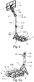
Fig.1 ] représente en perspective vue de l'avant un équipement selon un premier mode de réalisation de l'invention en configuration d'utilisation, lafigure 1a représentant en perspective vue de l'arrière la base de ce même équipement ; - [
Fig.2 ] représente en vue latérale le montage de la planche et de l'anneau sur le tronçon supérieur de l'équipement de lafigure 1 ; - [
Fig.3 ] est un agrandissement en perspective vue de l'arrière du poteau de l'équipement desfigures 1, 1a et2 , centré sur le système d'actionnement du déplacement du tronçon supérieur, - [
Fig.3a ] et - [
Fig.3b ] tant des coupes de lafigure 3 suivant deux plans sagittaux différents ; [Fig.4a ] et - [
Fig.4b ] représentent l'équipement desfigures 1 à 3b en configuration de rangement, respectivement en perspective (figure 4a ) et en vue de l'arrière (figure 4b ) ; - [
Fig.5 ] et - [
Fig.5a ] représentent des vues analogues à respectivement lesfigures 1 et 1a , pour un équipement suivant un deuxième mode de réalisation de l'invention ; [Fig.6 ] représente une vue analogue à lafigure 2 pour l'équipement desfigures 5 et 5a ; - [
Fig.7 ], - [
Fig.7a ] et - [
Fig.7b ] représentent des vues analogue à respectivement lesfigures 3, 3a et3b , pour l'équipement desfigures 5, 5a et6 ; - [
Fig.8a ] et - [
Fig.8b ] représentent l'équipement desfigures 5 à 7b en configuration de rangement, respectivement en vue de l'arrière (figure 8a ) et en perspective (figure 8b ) ; - [
Fig.9 ] représente en perspective vue de l'arrière un équipement selon un troisième mode de réalisation de l'invention en configuration d'utilisation, lafigure 9a représentant en perspective vue de l'arrière le tronçon inférieur du poteau et la base de ce même équipement ; - [
Fig.10 ] est un agrandissement en perspective vue de l'arrière du poteau de l'équipement desfigures 9, 9a , centré sur le système d'actionnement du déplacement du tronçon supérieur, - [
Fig.10a ] et - [Fig.lOb] étant des coupes du système d'actionnement de la
figure 10 suivant deux plans sagittaux différents ; - [
Fig.11a ], - [
Fig.11b ] et - [
Fig.11c ] représentent l'équipement desfigures 9, 9a ,10, 10a et 10b en configuration de rangement, respectivement en vue de l'arrière (figure 11a ) et en perspective suivant deux orientations différentes (figures 11b ,11c ) ; - [
Fig.12a ], - [
Fig.12b ] et - [
Fig.12c ] représentent en perspective vue de l'arrière le montage de la planche sur le tronçon supérieur du poteau dans l'équipement desfigures 9 à 11c , respectivement en position d'utilisation (figure 12a ), en position de rangement (figure 12b ) et en vue éclatée (figure 12c ) ; - [
Fig.13 ] est un agrandissement de lafigure 12a centré sur l'organe de butée définissant la position d'utilisation de la planche ; - [
Fig.14 ] est une vue en coupe partielle suivant un plan sagittal du mécanisme de montage de la planche sur le tronçon supérieur du poteau dans l'équipement desfigures 9 à 13 . - En relation avec ces figures, on décrit ci-dessous un équipement pour la pratique du basketball.
- L'équipement comprend une base 1 destinée à être disposée en appui sur le sol, ainsi qu'un poteau 2 présentant un tronçon supérieur 2a portant une planche 3 sur laquelle un anneau de basketball 4 est monté.
- Le poteau 2 présente un tronçon inférieur 2b qui est monté en rotation sur la base 1 pour pouvoir disposer ledit poteau réversiblement entre une configuration rabattue de rangement et une configuration dressée d'utilisation.
- La base 1 est équipée de deux structures latérales 5 qui forment entre elles un logement 6 tel que, en configuration de rangement, au moins le tronçon inférieur 2b du poteau 2 est disposé dans ledit logement. Dans les modes de réalisation représentés, la base 1 comprend un châssis 7 sur lequel le tronçon inférieur 2b est monté en rotation, les structures latérales 5 étant portées par ledit châssis en formant un logement en U 6 entre elles.
- Les deux structures latérales 5 forment un contrepoids au poteau 2 en configuration dressée pour l'utilisation de l'équipement, afin d'éviter un basculement dudit équipement, et ainsi garantir la sécurité de ses utilisateurs.
- Au moins une structure latérale 5 peut être agencée pour pouvoir être remplie avec une matière de lest, par exemple de l'eau ou du sable. Dans les deuxième et troisième modes de réalisation représentés (respectivement sur les
figures 5, 5a ,8a, 8b et sur lesfigures 9, 9a ,11a, 11b ,11c ), chaque structure latérale 5 présente trois modules 5a alignés suivant une direction sagittale, chacun desdits modules comprenant un réservoir 8 sur lequel une ouverture 9 est disposée pour permettre leur remplissage avec une telle matière de lest. - Pour une bonne répartition du poids, dans chacun des modes de réalisation représentés, les structures latérales 5 présentent des modules identiques 5a qui sont répartis de manière symétrique par rapport aux modules 5a de l'autre structure latérale 5, de part et d'autre d'un plan sagittal médian contenant le poteau 2.
- La base 1 est en outre équipée de roues 10 pour permettre le déplacement de l'équipement, notamment dans sa configuration de rangement.
- Dans les deux premiers modes de réalisation représentés (
figures 1 à 4b etfigures 5 à 8b respectivement), le châssis 7 forme un berceau sur lequel les structures latérales 5 sont disposées, ledit berceau portant au moins une paire de roues 10. - En particulier, dans le premier mode de réalisation (
figures 1 à 4b ), le châssis 7 présente une géométrie en U dont les branches 7a s'étendent vers l'arrière suivant une direction sagittale, en présentant chacune une roue arrière 10 qui est fixée à leur extrémité libre respective de manière à être surélevée lorsque la base 1 est à plat sur le sol, ce qui permet d'éviter tout déplacement intempestif de l'équipement, notamment lors de son utilisation. - Ainsi, pour pouvoir déplacer l'équipement, l'utilisateur doit légèrement surélever la base 1 du côté avant, notamment en saisissant manuellement une barre transversale avant 7b formant la base du U du châssis 7, afin de mettre les roues arrière 10 en appui sur le sol.
- Dans le deuxième mode de réalisation (
figures 5 à 8b ), le châssis 7 présente un cadre 7d de géométrie sensiblement rectangulaire qui est équipé de quatre roues 10 réparties en chacun de ses coins. En particulier, les roues avant 10a sont montées chacune en rotation sur le châssis 7 autour d'un axe vertical 11 indépendant, afin de permettre à l'utilisateur de diriger facilement l'équipement lorsqu'il le fait rouler sur le sol. - Dans le troisième mode de réalisation représenté (
figures 9 à 14 ), la base 1 est équipée de deux rangées de roues 10 formant chacune une structure latérale 5 entre lesquelles est formé le logement 6 de réception du tronçon inférieur 2b en configuration rabattue. - En particulier, chacune des roues 10 forme un module de lest 5a pour la structure latérale 5 correspondante, et présente à cet effet un réservoir cylindrique 8 sur la périphérie duquel une ouverture 9 est disposée pour permettre son remplissage avec une matière de lest, l'axe de révolution dudit réservoir s'étendant horizontalement et perpendiculairement à l'axe sagittal du châssis 7, afin de pouvoir déplacer la base 1 en faisant rouler lesdits réservoirs sur leur périphérie.
- Sur les
figures 9, 9a et11a à 11c , le châssis 7 comprend une poutre centrale 7c de part et d'autre de laquelle les roues 10 sont montées. En particulier, les roues 10 comprennent chacune un moyeu 12 solidarisé à la poutre centrale 7c, lesdits moyeux étant agencés pour permettre aux roues 10 de tourner indépendamment les unes des autres. - S'agissant du montage du tronçon inférieur 2b, le berceau 7a, 7b, 7d ou la poutre centrale 7c du châssis 7 présente une partie avant sur le(la)quel(le) ledit tronçon inférieur est monté en rotation. Ainsi, pour disposer l'équipement en configuration d'utilisation, l'utilisateur déplace d'abord le tronçon inférieur 2b de la configuration rabattue à la configuration dressée en le faisant pivoter par rapport à la partie avant du châssis 7.
- Pour faciliter sa disposition en configuration d'utilisation, l'équipement comprend un bras de liaison 13 qui présente une extrémité avant 13a articulée sur le tronçon inférieur 2b, ainsi qu'une extrémité arrière articulée sur la base 1, notamment en étant disposée dans le logement 6 de réception dudit tronçon inférieur.
- Dans le premier mode de réalisation représenté (
figures 1, 1a ,4a, 4b ), le bras de liaison 13 présente deux segments 14 qui sont articulés au niveau d'une charnière centrale 15 pour pouvoir être réversiblement disposés dans une configuration déployée de maintien du poteau 2 dressé et une configuration pliée de rangement. - En particulier, la charnière centrale 15 comprend une goupille 16 de verrouillage du bras 13 en configuration déployée pour éviter son pliage intempestif, et ainsi limiter les risques de basculement du tronçon inférieur 2b durant l'utilisation de l'équipement. La goupille 13 est actionnable manuellement pour permettre son déplacement de la position de verrouillage vers une position déverrouillée, afin de libérer la rotation relative des segments 14 et permettre le basculement du bras 13 en configuration pliée.
- Dans les deux autres modes de réalisation représentés, au moins l'une parmi les extrémités avant 13a et arrière du bras de liaison 13 est montée en coulissement sur respectivement le tronçon inférieur 2b et la base 1.
- Dans le deuxième mode de réalisation (
figures 5, 5a ), le bras de liaison 13 comprend une extrémité avant 13a montée en rotation sur un chariot 19 qui coulisse sur un rail vertical 17 monté sur une face arrière du tronçon inférieur 2b, ainsi qu'une extrémité arrière montée en rotation sur le châssis 7. - En particulier, le chariot 19 comprend une goupille 20 de verrouillage qui est agencée pour être disposée réversiblement dans un orifice 21 supérieur et/ou inférieur formé(s) sur le rail 17, afin de bloquer ledit chariot en position haute et/ou basse, et ainsi verrouiller le tronçon inférieur 2b en configuration rabattue et/ou dressée.
- Dans le troisième mode de réalisation (
figures 9, 9a ), le bras de liaison 13 comprend une extrémité avant 13a montée en rotation sur une face arrière du tronçon inférieur 2b et une extrémité arrière montée en rotation et en coulissement sur un rail horizontal formé sur la poutre centrale 7c. - Le tronçon inférieur 2b est en outre équipé d'au moins un pied 18 qui est disposé latéralement, afin de stabiliser le poteau 2 en configuration dressée, notamment pour prévenir son basculement sur les côtés, en combinaison avec la base 1 qui forme un contrepoids pour éviter son basculement vers l'avant ou l'arrière.
- Sur les figures, le tronçon inférieur 2b comprend deux pieds 18 disposés de part et d'autre de son extrémité inférieure. Sur les
figures 1, 1a ,4a et 4b , les pieds 18 sont montés en rotation sur la base 1 et sur le tronçon inférieur 2b. Sur lesfigures 5, 5a ,8b ,9, 9a et11c , les pieds 18 sont fixés sur le tronçon inférieur 2b pour venir en appui sur le sol lorsque le poteau 2 est en configuration dressée, ce qui permet également d'empêcher la base 1 de rouler lorsque l'équipement est en configuration d'utilisation. - Le tronçon supérieur 2a est monté en coulissement sur le tronçon inférieur 2b, l'équipement comprenant un système d'actionnement 22 de ce déplacement sur une course comprise entre une position rétractée de rangement et au moins une position saillante correspondant à une hauteur d'utilisation.
- En relation avec les
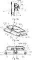
figures 3, 3a ,3b ,7, 7a ,7b ,10, 10a et 10b , le système d'actionnement 22 comprend un boîtier 23 fixé sur une paroi arrière du tronçon inférieur 2b et un mécanisme de déplacement du tronçon supérieur 2a qui est logé dans ledit boîtier, ledit mécanisme comprenant une prise de manipulation 24 qui est saillante dudit boitier. - En particulier, la prise 24 est disposée sur une paroi arrière 23a du boîtier 23, et le logement 6 de la base 1 est agencé pour recevoir le tronçon inférieur 2b en configuration rabattue en empêchant l'accès à ladite prise, comme représenté sur les
figures 4b ,8a et11a . - Ainsi, on limite de façon optimale le risque de déploiement intempestif du tronçon supérieur 2a lorsque l'équipement est en configuration de rangement, et ce sans avoir à apporter de modifications importantes à la géométrie du logement 6, et donc de la base 1.
- Dans les modes de réalisation représentés, le tronçon supérieur 2a est monté en coulissement dans le tronçon inférieur 2b. En particulier, comme représenté sur les
figures 3, 3a ,7, 7a ,10 et 10a , le système d'actionnement 22 comprend une rangée verticale d'orifices 25 formée sur la face arrière du tronçon supérieur 2a et un mécanisme comprenant une roue dentée 26 qui est actionnée en rotation par une vis sans fin 27, ladite roue étant agencée pour s'engager successivement dans les orifices 25 pour le coulissement du tronçon supérieur 2a dans le tronçon inférieur 2b. - La roue dentée 26 est montée en rotation dans le boîtier 23 selon un axe frontal A1, et la vis 27 est montée en rotation dans le boîtier 23 selon un axe sagittal A2. La vis 27 présente une extrémité arrière 27a qui est saillante de la paroi arrière 23a du boîtier 23 et sur laquelle est fixée une boucle métallique 24 formant une prise de manipulation pour le mécanisme.
- De façon avantageuse, une manivelle 28 peut être associée de façon réversible sur la boucle 24 de manipulation de la vis 27, de manière à être retirée de ladite boucle lorsque le mécanisme n'est pas actionné. Cet agencement permet non seulement de limiter l'encombrement du système 22 lors de sa disposition dans le logement 6, mais également de limiter le risque d'actionnement intempestif du mécanisme lorsque l'équipement est en configuration d'utilisation, afin de garantir la sécurité des utilisateurs.
- Le mécanisme d'actionnement comprend deux roues dentées 26, 29 de diamètre différent qui sont solidaires en rotation. En relation avec les figures en coupe 3a, 3b, 7a, 7b, 10a et 10b, la roue de grand diamètre 26 est engagée dans les orifices 25 et la roue de petit diamètre 29 est actionnée par la vis sans fin 27.
- La vis sans fin 27 peut être agencée pour nécessiter une manipulation de la prise 24 pour actionner le tronçon supérieur 2a dans chacun de ses sens de déplacement. Ainsi, on empêche notamment une rotation des roues 26, 29 dans le sens de rétractation du tronçon supérieur 2a lorsque la vis 27 n'est pas actionnée, ce qui permet d'assurer le maintien dudit tronçon supérieur à la hauteur choisie, afin de garantir la sécurité des utilisateurs en empêchant sa rétractation intempestive dans le tronçon inférieur 2b durant l'utilisation de l'équipement.
- Pour limiter l'encombrement de l'équipement en configuration de rangement, le tronçon supérieur 2a du poteau 2 comprend un segment supérieur 30a portant la planche 3 et un segment inférieur 30b monté en coulissement sur le tronçon inférieur 2b, ledit segment supérieur étant monté mobile par rapport audit segment inférieur entre une configuration d'utilisation, dans laquelle ledit segment supérieur est déployé par rapport audit segment inférieur, et une configuration de rangement, dans laquelle ledit segment supérieur forme un agencement compact avec ledit segment inférieur.
- Ainsi, une fois que le tronçon inférieur 2b est en position dressée, l'utilisateur peut disposer l'équipement en configuration d'utilisation en déployant successivement le segment inférieur 30b hors dudit tronçon inférieur, par actionnement du système 22 au moyen de la manivelle 28, puis le segment supérieur 30a par rapport audit segment inférieur.
- Dans les deux premiers modes de réalisation représentés (
figures 1 ,5 ), le segment supérieur 30a est monté en coulissement sur le segment inférieur 30b, l'équipement comprenant un système 22' d'actionnement dudit déplacement sur une course comprise entre une position rétractée de rangement et au moins une position saillante correspondant à une hauteur d'utilisation. - En particulier, ce système d'actionnement 22' comprend un boîtier 23' fixé sur une paroi arrière du segment inférieur 30b et un mécanisme de déplacement du segment supérieur 30a qui est logé dans ledit boîtier, ledit mécanisme comprenant une prise de manipulation 24' qui est saillante dudit boîtier.
- De façon avantageuse, la prise de manipulation 24' de ce système 22' est également disposée sur une paroi arrière du boîtier 23', et le logement 6 est agencé pour recevoir le segment inférieur 30b en configuration rabattue en empêchant l'accès à ladite prise, comme représenté sur les
figures 4b et8a . - Selon un mode de réalisation préféré de l'invention, les systèmes d'actionnement respectifs 22, 22' du segment inférieur 30b et du segment supérieur 30a sont analogues, ce qui permet de faciliter la fabrication de l'équipement. En particulier, l'équipement peut comprendre une manivelle unique 28 qui peut être fixée sélectivement et de manière réversible sur la prise de manipulation 24, 24' de l'un ou l'autre de ces systèmes lors du déploiement dudit équipement en configuration d'utilisation.
- Dans le troisième mode de réalisation représenté (
figures 9, 9a ), le segment supérieur 30a est monté en rotation sur le segment inférieur 30b entre une configuration angulaire dressée d'utilisation et une configuration angulaire repliée de rangement contre le segment inférieur 30b. - En particulier, le segment supérieur 30a comprend au moins une paire de barres parallèles 31 qui présentent chacune une extrémité arrière montée en rotation sur l'extrémité supérieure du segment inférieur 30b, ainsi qu'une extrémité avant sur laquelle la planche 3 est montée en rotation suivant un axe frontal. Ainsi, le segment supérieur 30a forme un parallélogramme déformable qui permet à l'utilisateur de déployer angulairement ledit segment supérieur et de dresser la planche 3 en un seul geste.
- L'équipement peut comprendre en outre un système 32 de verrouillage du segment supérieur 30a en configuration dressée, afin d'éviter tout basculement intempestif dudit segment supérieur en configuration repliée, notamment durant l'utilisation dudit équipement, et ainsi assurer la sécurité des utilisateurs.
- Sur la
figure 9 , le système de verrouillage 32 comprend un boîtier 33 qui est monté sur l'extrémité supérieure du segment inférieur 30b, et sur chaque face latérale duquel l'extrémité arrière d'une barre parallèle supérieure 31 est montée en rotation, ledit boîtier renfermant un mécanisme de verrouillage qui est actionnable réversiblement au moyen d'un levier à bascule 34 monté en partie supérieure dudit boîtier. - De façon avantageuse, la planche 3 est déplaçable par rapport au segment supérieur 30a entre une position d'utilisation et une position de rangement, ce qui permet de limiter l'encombrement de l'équipement en configuration de rangement.
- Dans les trois modes de réalisation représentés, la planche 3 présente une géométrie quadrilatérale, notamment rectangulaire, qui, en position de rangement, est tournée de 90° par rapport à sa position d'utilisation sur le segment supérieur 30a. En particulier, la planche 3 présente des dimensions longitudinales et latérales qui correspondent sensiblement aux dimensions respectivement sagittales et frontales de la base 1. Ainsi, dans la mesure où la base 1 présente une dimension sagittale qui est supérieure à sa dimension frontale pour pouvoir assurer la stabilité de l'équipement vis-à-vis d'un basculement avant-arrière, il est possible, dans l'encombrement de ladite base, de ranger une planche rectangulaire qui satisfait à la pratique sportive.
- Dans les deux premiers modes de réalisation représentés, la planche 3 est montée de façon réversible sur le segment supérieur 30a entre une position montée d'utilisation et une position démontée de rangement, le poteau 2 en configuration de rangement permettant le rangement de la planche 3 démontée sur la base.
- Pour ce faire, en relation avec les
figures 2 et6 , la planche 3 est équipée d'un connecteur 35 dans lequel l'extrémité supérieure du segment supérieur 30a est disposée, ledit connecteur présentant une paroi transversale 35a sur laquelle ladite extrémité supérieure est en appui en position d'utilisation. - Sur la
figure 2 , le connecteur 35 comprend un boîtier 59 fixé sur la face arrière de la planche 3 et définissant un logement de réception de l'extrémité supérieure du segment supérieur 30a, ladite extrémité venant en appui sous une paroi supérieure 35a dudit boîtier lorsque la planche est montée en position d'utilisation. - Le connecteur 35 est équipé d'une goupille de verrouillage 36 qui est actionnable entre une position stable de blocage, dans laquelle ladite goupille est engagée dans un orifice prévu à cet effet dans le segment supérieur 30a, et une position contrainte de montage, dans laquelle ladite goupille est rétractée de l'orifice.
- Sur les
figures 6 et8b , le connecteur 35 comprend un évidement vertical 60 formé sur le bord inférieur de la planche 3, et délimité en partie haute par une paroi transversale sous laquelle l'extrémité supérieure du segment supérieur 30a vient en appui lors du montage de ladite planche sur le poteau 2. - En particulier, le connecteur 35 comprend une patte verticale 61 qui s'étend dans l'évidement 60, ladite patte étant agencée pour être disposée dans un logement vertical complémentaire 62 prévu à cet effet dans l'extrémité supérieure du segment supérieur 30a.
- Le segment supérieur 30a est équipé d'une goupille de verrouillage 36' qui est actionnable entre une position stable de blocage, dans laquelle ladite goupille traverse le logement 62 du segment supérieur 30a pour s'engager sur une butée de verrouillage prévue à cet effet sur la patte 61 du connecteur 35, et une position contrainte de montage, dans laquelle ladite goupille est rétractée hors dudit logement.
- Dans ces deux modes de réalisation, la goupille de verrouillage 36, 36' comprend une extrémité intérieure destinée à être engagée dans l'orifice du segment 30a ou sur la butée de la patte 61, ainsi qu'une extrémité extérieure sur laquelle est montée une poignée 37, 37' pour permettre à l'utilisateur de déplacer ladite goupille vers sa position contrainte de montage par traction sur ladite poignée.
- Par ailleurs, la goupille 36, 36' est équipée d'un moyen de contrainte élastique, par exemple sous la forme d'un ressort, qui est agencé pour être contraint élastiquement lors d'une traction sur la poignée 37, 37' afin de rappeler élastiquement ladite goupille vers sa position stable lorsque l'utilisateur relâche ladite poignée.
- Dans le premier mode de réalisation (
figures 4a et 4b ), au moins une structure latérale 5 présente un logement 38 de réception du boitier 59 lorsque la planche 3 est en configuration de rangement sur la base 1, afin d'assurer une retenue de ladite planche sur ladite base. - De façon avantageuse, chaque structure latérale 5 présente un tel logement 38, ce qui permet à l'utilisateur de disposer la planche 3 démontée sur la base 1 en disposant indifféremment le connecteur 35 sur l'une desdites structures latérales.
- Dans le troisième mode de réalisation représenté (
figures 9 à 14 ), la planche 3 est montée en rotation sur le segment supérieur 30a entre une position angulaire d'utilisation (figures 9 ,12a ,12c ) et une position angulaire de rangement (figures 11a à 11c etfigure 12b ), notamment par l'intermédiaire d'un mécanisme 39 de rotation entre ces deux positions. - En relation avec les
figures 12a à 14 , le mécanisme de rotation 39 comprend une platine 40 d'association de l'extrémité supérieure du segment supérieur 30a, ladite platine comprenant une extension 41 liée à la planche par l'intermédiaire d'un pivot à friction. Comme représenté sur lafigure 12a , l'extension 41 est disposée au-dessus du segment supérieur 30a lorsque la planche 3 est en position d'utilisation. - L'extension 41 de la platine 40 comprend une structure en U dont les deux branches 42 portent des moyens d'association de l'extrémité supérieure du tronçon supérieur, la base 42a dudit U étant engagée dans la liaison pivot à friction.
- En particulier, chaque branche 42 présente une paire de plaques latérales 43 verticales entre lesquelles l'extrémité supérieure de respectivement une barre 31 est montée en rotation.
- L'extension 41 est serrée contre la planche 3 avec au moins un insert de friction 45 interposé entre elles, l'équipement comprenant en outre un moyen 46 d'ajustement du serrage afin d'optimiser le couple de friction de la rotation.
- Pour ce faire, le mécanisme de rotation 39 comprend une coupelle arrière 47 fixée sur la face arrière de la planche 3 et une coupelle avant 48, l'extension 41 étant disposée entre les coupelles 47, 48 qui sont équipées de moyens 46 de serrage de ladite extension entre elles, au moins une coupelle 47, 48 logeant un insert de friction 45.
- Sur les
figures 12a ,12b ,12c et14 , chaque coupelle 47, 48 loge un insert de friction 45, l'extension 41 étant serrée entre lesdites coupelles et fixée à l'arrière de la planche 3 au moyen de quatre vis 46. - Chaque insert 45 est immobilisé en rotation entre les coupelles 47, 48, et comprend une couronne de friction 45a qui est serrée sur une face respectivement arrière 41b et avant 41a de l'extension 41 par l'intermédiaire d'une couronne de serrage 47a, 48a formée sur la coupelle 47, 48 adjacente.
- L'extension 41 présente une section carrée, comme représenté notamment sur la
figure 14 , ou rectangulaire, une couronne de friction 45a étant serrée contre respectivement une face avant 41a et une face arrière 41b de ladite section. - Chaque couronne de serrage 47a, 48a présente des échancrures 49, et notamment deux échancrures 49 de dimensions angulaires identiques qui sont diamétralement opposées le long de ladite couronne.
- Après avoir disposé le tronçon inférieur 2b en configuration dressée, l'utilisateur peut disposer la planche 3 en position d'utilisation en la faisant pivoter au moyen du mécanisme de rotation 39. Ensuite, l'utilisateur peut faire pivoter le segment supérieur 30a pour le disposer en configuration dressée, puis ériger le segment inférieur 30b hors du tronçon inférieur 2b par actionnement de son système 22, jusqu'à la hauteur désirée pour la planche 3.
- La position d'utilisation de la planche 3 est délimitée par la mise en butée de la platine 40 sur un organe 50 solidaire de ladite planche. De façon avantageuse, l'organe 50 de butée de la planche 3 comprend un moyen 51 de verrouillage de la position d'utilisation, ce qui permet de sécuriser ladite position, notamment en évitant toute rotation intempestive de ladite planche lors de l'utilisation de l'équipement.
- En relation avec la
figure 13 , le moyen de verrouillage est un loquet 51 qui s'engage réversiblement sur un axe 52 solidaire de la platine 40. En particulier, l'axe 52 est fixé sur l'extrémité inférieure de l'une des branches 43 de l'extension en U 41, et le loquet 51 comprend un crochet 51a qui vient s'engager sur ledit axe en position de verrouillage, ainsi qu'une patte 51b que l'utilisateur peut saisir manuellement pour faire pivoter le loquet 51 et dégager le crochet 51a dudit axe, lorsqu'il souhaite faire pivoter la planche 3 vers sa position de rangement. - Comme représenté sur la
figure 12c , l'anneau 4 est fixé sur la planche 3 de façon à ne pas interagir avec la platine 40 lors de la rotation de ladite planche. Pour ce faire, l'anneau 4 comprend un support 53 qui est fixé sur la planche 3 de façon mécaniquement indépendante de la platine 40. - De façon avantageuse, l'anneau 4 présente une extension 4a qui est montée en rotation autour d'un axe 54 solidaire de son support 53 de fixation à la planche 3, de sorte que ledit anneau soit repliable depuis une position horizontale d'utilisation vers une position verticale de rangement contre la planche 3, afin de limiter l'encombrement dudit anneau dans la configuration de rangement de l'équipement.
- Pour ce faire, le support 53 présente deux flans verticaux 53a qui s'étendent depuis une face avant de la planche 3 suivant une direction sagittale, l'extension 4a étant montée en rotation sur un axe frontal 54 fixé entre lesdits flans.
- En particulier, dans le troisième mode de réalisation représenté, le support 53 comprend également :
- un fond 53b s'étendant frontalement à l'arrière de ses flans verticaux 53b, et fixé à la planche 3 au moyen de vis ; et
- un second axe frontal 55 fixé entre ses flans verticaux 53b, sur lequel l'extension 4a de l'anneau 4 vient en butée lorsque ledit anneau est disposé en position d'utilisation.
- Dans les premier et deuxième modes de réalisation représentés, l'anneau 4 est équipé d'un arceau de maintien 56 qui présente deux bras 56a montés en rotation sous ledit anneau et une base 56b engagée réversiblement dans une butée formée sur le support 53 pour définir la position d'utilisation.
- En relation avec les
figures 2 ,4a et 4b , le support 53 comprend deux fentes 57 formées sur respectivement un flan vertical 53a, dans lesquelles la base 56b coulisse lors de la rotation de l'anneau 4 en définissant la position d'utilisation par mise en butée de ladite base sur les bords inférieurs desdites fentes (figure 2 ). En particulier, comme représenté sur lesfigures 4a et 4b , la base 56b vient également en butée sur les bords supérieurs des fentes 57 en position de rangement de l'anneau 4. - Sur la
figure 6 , la base 56b vient en butée en partie inférieure du support 53 pour définir la position d'utilisation de l'anneau 4, et l'équipement comprend un loquet 58 de verrouillage de ladite base sur ladite butée.
Claims (15)
- Equipement pour la pratique du basketball, comprenant une base (1) destinée à être disposée en appui sur le sol, ladite base étant équipée de deux structures latérales (5) formant entre elles un logement (6), ledit équipement comprenant un poteau (2) présentant un tronçon supérieur (2a) portant une planche (3) sur laquelle un anneau de basketball (4) est monté, ledit poteau présentant un tronçon inférieur (2b) qui est monté en rotation sur ladite base pour pouvoir disposer ledit poteau réversiblement entre une configuration rabattue de rangement dans laquelle au moins le tronçon inférieur (2b) est disposé dans le logement (6) et une configuration dressée d'utilisation, ledit tronçon supérieur étant monté en coulissement sur ledit tronçon inférieur et ledit équipement comprenant un système (22) d'actionnement dudit déplacement sur une course comprise entre une position rétractée de rangement et au moins une position saillante correspondant à une hauteur d'utilisation, ledit système d'actionnement comprenant un boitier (23) fixé sur une paroi arrière du tronçon inférieur (2b) et un mécanisme de déplacement du tronçon supérieur (2a) qui est logé dans ledit boîtier, ledit mécanisme comprenant une prise (24) de manipulation qui est saillante du boîtier (23), ledit équipement étant caractérisé en ce que ladite prise est disposée sur une paroi arrière (23a) du boîtier (23) et en ce que le logement (6) est agencé pour recevoir le tronçon inférieur (2b) en configuration rabattue en empêchant l'accès à ladite prise.
- Equipement selon la revendication 1, caractérisé en ce que les deux structures latérales (5) forment un contrepoids au poteau (2) en configuration dressée pour l'utilisation dudit équipement.
- Equipement selon l'une des revendications 1 ou 2, caractérisé en ce que la base (1) comprend un châssis (7) sur lequel le tronçon inférieur (2b) est monté en rotation, les structures latérales (5) étant portées par ledit châssis en formant un logement en U (6) entre elles.
- Equipement selon l'une quelconque des revendications 1 à 3, caractérisé en ce qu'il comprend un bras de liaison (13) qui présente une extrémité avant (13a) articulée sur le tronçon inférieur (2b) et une extrémité arrière articulée sur la base (1), ladite extrémité arrière étant disposée dans le logement (6).
- Equipement selon la revendication 4, caractérisé en ce que le bras de liaison (13) présente deux segments (14) qui sont articulés pour pouvoir être réversiblement disposés dans une configuration déployée de maintien du poteau (2) dressé et une configuration pliée de rangement.
- Equipement selon l'une quelconque des revendications 1 à 5, caractérisé en ce que le tronçon inférieur (2b) du poteau (2) est équipé d'au moins un pied (18) qui est disposé latéralement afin de stabiliser le poteau (2) en configuration dressée.
- Equipement selon l'une quelconque des revendications 1 à 6, caractérisé en ce que le tronçon supérieur (2a) est monté en coulissement dans le tronçon inférieur (2b), le système d'actionnement (22) comprenant une rangée verticale d'orifices (25) formée sur la face arrière du tronçon supérieur (2a) et un mécanisme comprenant une roue dentée (26) qui est actionnée en rotation par une vis sans fin (27), ladite roue dentée étant agencée pour s'engager successivement dans les orifices (25) pour le coulissement du tronçon supérieur (2a) dans le tronçon inférieur (2b).
- Equipement selon la revendication 7, caractérisé en ce que la roue dentée (26) est montée en rotation dans le boîtier (23) selon un axe frontal (A1), la vis (27) étant montée en rotation dans le boîtier (23) selon un axe sagittal (A2).
- Equipement selon l'une des revendications 7 ou 8, caractérisé en ce que le mécanisme d'actionnement comprend deux roues dentées (26, 29) de diamètre différent qui sont solidaires en rotation, la roue de grand diamètre (26) étant engagée dans les orifices (25) et la roue de petit diamètre (29) étant actionnée par la vis sans fin (27).
- Equipement selon l'une quelconque des revendications 7 à 9, caractérisé en ce qu'une manivelle (28) peut être associée de façon réversible sur la prise (24) de manipulation en rotation de la vis sans fin (27).
- Equipement selon l'une quelconque des revendications 7 à 10, caractérisé en ce que la vis sans fin (27) est agencée pour nécessiter une manipulation de la prise (24) pour actionner le tronçon supérieur (2a) dans chacun de ses sens de déplacement.
- Equipement selon l'une quelconque des revendications 1 à 11, caractérisé en ce que le tronçon supérieur (2a) du poteau (2) comprend un segment supérieur (30a) portant la planche (3) et un segment inférieur (30b) monté en coulissement sur le tronçon inférieur (2b), ledit segment supérieur étant monté en coulissement sur ledit segment inférieur, ledit équipement comprenant un système (22') d'actionnement dudit déplacement sur une course comprise entre une position rétractée de rangement et au moins une position saillante correspondant à une hauteur d'utilisation, le système d'actionnement (22') comprenant un boitier (23') fixé sur une paroi arrière du segment inférieur (30b) et un mécanisme de déplacement du segment supérieur (30a) qui est logé dans ledit boîtier, ledit mécanisme comprenant une prise de manipulation (24') qui est saillante du boîtier (23'), ladite prise est disposée sur une paroi arrière du boîtier (23'), le logement (6) étant agencé pour recevoir le segment inférieur (30b) en configuration rabattue en empêchant l'accès à ladite prise.
- Equipement selon l'une quelconque des revendications 1 à 12, caractérisé en ce que la planche (3) est montée en rotation sur le tronçon supérieur (2a) entre une position angulaire d'utilisation et une position angulaire de rangement.
- Equipement selon l'une quelconque des revendications 1 à 12, caractérisé en ce que la planche (3) est montée de façon réversible sur le tronçon supérieur (2a) entre une position montée d'utilisation et une position démontée de rangement, le poteau (2) en configuration de rangement permettant le rangement de la planche (3) démontée sur la base (1).
- Equipement selon l'une quelconque des revendications 1 à 14, caractérisé en ce que l'anneau (4) présente une extension latérale (4a) qui est montée en rotation autour d'un axe (54) solidaire d'un support (53) fixé sur la planche (3) de sorte que ledit anneau soit repliable depuis une position horizontale d'utilisation vers une position verticale de rangement contre ladite planche.
Applications Claiming Priority (1)
| Application Number | Priority Date | Filing Date | Title |
|---|---|---|---|
| FR2102296A FR3120543B1 (fr) | 2021-03-09 | 2021-03-09 | Equipement pour la pratique du basketball |
Publications (2)
| Publication Number | Publication Date |
|---|---|
| EP4056241A1 true EP4056241A1 (fr) | 2022-09-14 |
| EP4056241B1 EP4056241B1 (fr) | 2024-01-03 |
Family
ID=76920835
Family Applications (1)
| Application Number | Title | Priority Date | Filing Date |
|---|---|---|---|
| EP22160910.0A Active EP4056241B1 (fr) | 2021-03-09 | 2022-03-08 | Équipement pour la pratique du basketball |
Country Status (5)
| Country | Link |
|---|---|
| US (1) | US20220288475A1 (fr) |
| EP (1) | EP4056241B1 (fr) |
| CN (1) | CN115040848A (fr) |
| ES (1) | ES2977506T3 (fr) |
| FR (1) | FR3120543B1 (fr) |
Families Citing this family (5)
| Publication number | Priority date | Publication date | Assignee | Title |
|---|---|---|---|---|
| US12146334B2 (en) * | 2021-03-08 | 2024-11-19 | Diana Banjo | Convertible carrying case and securement system for a post |
| USD977601S1 (en) * | 2022-01-10 | 2023-02-07 | Meijuan Zheng | Basketball stand |
| USD1016942S1 (en) * | 2023-02-14 | 2024-03-05 | Zhicheng Huang | Pool basketball goal |
| USD1020954S1 (en) * | 2023-04-17 | 2024-04-02 | Zhicheng Huang | Basketball goal |
| USD1019836S1 (en) * | 2023-10-27 | 2024-03-26 | Xinjiang Huang | Basketball stand |
Citations (5)
| Publication number | Priority date | Publication date | Assignee | Title |
|---|---|---|---|---|
| DE29513110U1 (de) * | 1995-08-16 | 1995-10-19 | Sport-Thieme GmbH, 38368 Grasleben | Transportable Basketballanlage |
| US20070010356A1 (en) * | 2005-07-08 | 2007-01-11 | Moller Jorgen J Jr | Basketball hoop system |
| US20070232421A1 (en) * | 2006-03-06 | 2007-10-04 | Nye S C | Basketball system |
| FR3022796A1 (fr) | 2014-06-27 | 2016-01-01 | Decathlon Sa | Structure de jeu comprenant un element qui presente une premiere partie montee coulissante dans une deuxieme partie |
| FR3022795A1 (fr) | 2014-06-27 | 2016-01-01 | Decathlon Sa | Structure de jeu pour la pratique du basketball |
Family Cites Families (48)
| Publication number | Priority date | Publication date | Assignee | Title |
|---|---|---|---|---|
| US2383204A (en) * | 1945-01-31 | 1945-08-21 | Veque Gustave E Le | Lifting jack |
| US2838308A (en) * | 1956-03-02 | 1958-06-10 | Roosevelt I Polite | Basketball game apparatus |
| US2818254A (en) * | 1956-03-27 | 1957-12-31 | Bernard J Dunn | Swimming pool basket ball apparatus |
| US2831689A (en) * | 1956-04-27 | 1958-04-22 | Waldo G Marsh | Adjustable basketball backboard support |
| US3427025A (en) * | 1964-01-27 | 1969-02-11 | Elzie H Procter | Vertically adjustable basketball goal |
| US3669450A (en) * | 1969-08-04 | 1972-06-13 | John W Mason | Portable and adjustable miniature basketball goal |
| US3841631A (en) * | 1973-07-09 | 1974-10-15 | E Dolan | Portable basketball backstop construction |
| US3958786A (en) * | 1974-11-27 | 1976-05-25 | Mann Gary A | Stand for musical instruments |
| US4522394A (en) * | 1984-06-27 | 1985-06-11 | Alphe Broussard | Collapsible, movable apparatus for supporting health-sports devices |
| US4869501A (en) * | 1988-03-04 | 1989-09-26 | Bryce Jones | Basketball goal |
| US4913388A (en) * | 1988-09-28 | 1990-04-03 | Mccant Robert | Movable basketball backboard |
| US4946163A (en) * | 1989-04-10 | 1990-08-07 | Aakre Stewart C | Portable basketball backboard assembly |
| US5098092A (en) * | 1989-04-10 | 1992-03-24 | Aakre Stewart C | Portable foldable basketball backboard assembly |
| US5050866A (en) * | 1989-08-18 | 1991-09-24 | Fucci John P | Punching bag support device |
| US5060946A (en) * | 1990-10-05 | 1991-10-29 | Taylor James E | Volleyball practice device |
| US5156395A (en) * | 1991-12-20 | 1992-10-20 | Smith Philip J | Adjustable basketball goal |
| US5478068A (en) * | 1992-07-30 | 1995-12-26 | Porter Athletic Equipment Company | Wheeled portable basketball goal assembly |
| US5238251A (en) * | 1992-10-16 | 1993-08-24 | Staka Robert L | Volleyball training and monitoring apparatus |
| US5377976A (en) * | 1993-02-04 | 1995-01-03 | Lifetime Products, Inc. | Portable basketball system |
| US5390914A (en) * | 1993-07-29 | 1995-02-21 | Porter Athletic Equipment Company | Foldable, portable basketball goal assembly |
| US5540429A (en) * | 1993-12-30 | 1996-07-30 | Icon Health & Fitness, Inc. | Adjustable height basketball standard with telescoping tubes |
| US6053825A (en) * | 1994-02-03 | 2000-04-25 | Huffy Corporation | Portable basketball system having dual ballast tanks movable between compact and expanded positions |
| US5902197A (en) * | 1998-05-13 | 1999-05-11 | Huffy Corporation | Foldable portable basketball goal assembly |
| US5967523A (en) * | 1998-06-18 | 1999-10-19 | Brownlee; Wally | Target stand |
| US6117027A (en) * | 1999-01-21 | 2000-09-12 | Huffy Corporation | Sports assembly ballast system |
| US6419596B1 (en) * | 1999-02-16 | 2002-07-16 | Bemanali H. Dadbeh | Portable basketball apparatus |
| US20020165049A1 (en) * | 2001-05-07 | 2002-11-07 | Dadbeh Bemanali H. | Portable basketball apparatus |
| US7118500B2 (en) * | 2002-01-16 | 2006-10-10 | Lifetime Products, Inc. | Portable basketball system |
| US6726208B2 (en) * | 2002-03-08 | 2004-04-27 | Gerald A. Wilkus | Stand for targets |
| US7290744B2 (en) * | 2003-04-03 | 2007-11-06 | Baldasari Alan D | Break-away basketball goal system |
| US6991568B1 (en) * | 2004-07-09 | 2006-01-31 | Acas Design Co., Ltd. | Height adjustable basketball frame structure |
| US20070238559A1 (en) * | 2005-01-12 | 2007-10-11 | Nye S C | Basketball system |
| US7691015B2 (en) * | 2005-06-15 | 2010-04-06 | Lifetime Products, Inc. | Basketball goal system |
| US7413523B2 (en) * | 2006-02-14 | 2008-08-19 | Lien-Fu Lu | Foldable basketball stand |
| CN200998573Y (zh) * | 2007-01-09 | 2008-01-02 | 好孩子儿童用品有限公司 | 篮球架 |
| CN101134135A (zh) * | 2007-10-12 | 2008-03-05 | 陈烁 | 可升降篮球架 |
| US8651492B1 (en) * | 2010-08-30 | 2014-02-18 | Paul Cappuccio | Drinking game |
| FR3022794B1 (fr) * | 2014-06-27 | 2016-07-29 | Decathlon Sa | Structure de jeu comprenant une base disposee en appui sur le sol |
| CN204395370U (zh) * | 2015-02-15 | 2015-06-17 | 潍坊医学院 | 一种高度可调节篮球架 |
| US10040600B1 (en) * | 2017-02-03 | 2018-08-07 | Jonathan Robbins | Reconfigurable pallet with integrated storage compartment |
| CN206715230U (zh) * | 2017-05-16 | 2017-12-08 | 湖南工程学院 | 一种室内用折叠篮球架 |
| CN209302133U (zh) * | 2018-12-12 | 2019-08-27 | 西安财经学院行知学院 | 一种可调节高度篮球训练用篮球架 |
| CN110393903B (zh) * | 2019-08-27 | 2020-12-22 | 浙江五饼二鱼实业有限公司 | 一种青少年篮球训练用的篮球架 |
| US20210213337A1 (en) * | 2020-01-15 | 2021-07-15 | Indian Industries, Inc. | Adjustable basketball goal |
| US12146334B2 (en) * | 2021-03-08 | 2024-11-19 | Diana Banjo | Convertible carrying case and securement system for a post |
| US12134016B2 (en) * | 2021-04-29 | 2024-11-05 | Russell Brands, Llc | Portable basketball goal assembly |
| US20230241471A1 (en) * | 2021-05-13 | 2023-08-03 | Shawn Reed | Rotary lift adjustable basketball goal |
| US11738233B1 (en) * | 2022-06-28 | 2023-08-29 | Donald Paul Cohen | Apparatus for exercise |
-
2021
- 2021-03-09 FR FR2102296A patent/FR3120543B1/fr active Active
-
2022
- 2022-03-08 EP EP22160910.0A patent/EP4056241B1/fr active Active
- 2022-03-08 US US17/689,013 patent/US20220288475A1/en active Pending
- 2022-03-08 ES ES22160910T patent/ES2977506T3/es active Active
- 2022-03-09 CN CN202210222593.0A patent/CN115040848A/zh active Pending
Patent Citations (5)
| Publication number | Priority date | Publication date | Assignee | Title |
|---|---|---|---|---|
| DE29513110U1 (de) * | 1995-08-16 | 1995-10-19 | Sport-Thieme GmbH, 38368 Grasleben | Transportable Basketballanlage |
| US20070010356A1 (en) * | 2005-07-08 | 2007-01-11 | Moller Jorgen J Jr | Basketball hoop system |
| US20070232421A1 (en) * | 2006-03-06 | 2007-10-04 | Nye S C | Basketball system |
| FR3022796A1 (fr) | 2014-06-27 | 2016-01-01 | Decathlon Sa | Structure de jeu comprenant un element qui presente une premiere partie montee coulissante dans une deuxieme partie |
| FR3022795A1 (fr) | 2014-06-27 | 2016-01-01 | Decathlon Sa | Structure de jeu pour la pratique du basketball |
Also Published As
| Publication number | Publication date |
|---|---|
| FR3120543B1 (fr) | 2023-03-17 |
| ES2977506T3 (es) | 2024-08-26 |
| CN115040848A (zh) | 2022-09-13 |
| FR3120543A1 (fr) | 2022-09-16 |
| EP4056241B1 (fr) | 2024-01-03 |
| US20220288475A1 (en) | 2022-09-15 |
Similar Documents
| Publication | Publication Date | Title |
|---|---|---|
| EP4056241B1 (fr) | Équipement pour la pratique du basketball | |
| EP2174860B1 (fr) | Trottinette pliable | |
| CA2952924A1 (fr) | Structure de jeu pour la pratique du basketball | |
| EP1201549B1 (fr) | Conteneur à embase en forme de palette et à parois repliables | |
| EP4056242B1 (fr) | Equipement pour la pratique du basketball | |
| EP2946994B1 (fr) | Remorque pour véhicule à deux roues | |
| EP3160600B1 (fr) | Structure de jeu comprenant une base disposée en appui sur le sol | |
| EP1005809B1 (fr) | Ensemble à déploiement latéral stable du genre bureau ou table | |
| EP3400622A1 (fr) | Abri stationnaire de stockage d'au moins une unité de stockage d'énergie électrique | |
| EP1186384A1 (fr) | Caisse à outils mobile et adaptée à un travail en hauteur | |
| FR3101604A1 (fr) | Trottinette pliable | |
| EP0680270B1 (fr) | Dispositif porte-bebe a usage multiple | |
| FR2795652A1 (fr) | Chariot pliable pour sac de golf, possedant des moyens de verrouillage perfectionnes | |
| EP1238896A1 (fr) | Timon articulé pour chariot de magasinage | |
| FR2777929A1 (fr) | Plate-forme telescopique | |
| EP3822147B1 (fr) | Système mécanique de mise à niveau automatique pour véhicule à bras | |
| EP0447338A1 (fr) | Dispositif porte-charge adaptable sur l'attelage à rotule d'un véhicule | |
| FR2867954A3 (fr) | Dispositif de transport | |
| FR2633567A1 (fr) | Dispositif de manutention d'une charge portee par un vehicule | |
| FR3066686B1 (fr) | Dispositif d’appui assis-debout et poste de travail manuel equipe de celui-ci | |
| EP4406705A1 (fr) | Servante à rouleau et/ou à billes | |
| EP4397291A1 (fr) | Fauteuil roulant motorise pliable et demontable | |
| FR3118399A1 (fr) | Accessoire pliable et kit monte-escaliers pour valise, methode de gravissement ou de descente d’escaliers avec une valise | |
| WO2003092438A2 (fr) | Tabourets extensibles | |
| FR3101605A1 (fr) | Trottinette pliable |
Legal Events
| Date | Code | Title | Description |
|---|---|---|---|
| PUAI | Public reference made under article 153(3) epc to a published international application that has entered the european phase |
Free format text: ORIGINAL CODE: 0009012 |
|
| STAA | Information on the status of an ep patent application or granted ep patent |
Free format text: STATUS: THE APPLICATION HAS BEEN PUBLISHED |
|
| AK | Designated contracting states |
Kind code of ref document: A1 Designated state(s): AL AT BE BG CH CY CZ DE DK EE ES FI FR GB GR HR HU IE IS IT LI LT LU LV MC MK MT NL NO PL PT RO RS SE SI SK SM TR |
|
| STAA | Information on the status of an ep patent application or granted ep patent |
Free format text: STATUS: REQUEST FOR EXAMINATION WAS MADE |
|
| 17P | Request for examination filed |
Effective date: 20230313 |
|
| RBV | Designated contracting states (corrected) |
Designated state(s): AL AT BE BG CH CY CZ DE DK EE ES FI FR GB GR HR HU IE IS IT LI LT LU LV MC MK MT NL NO PL PT RO RS SE SI SK SM TR |
|
| GRAP | Despatch of communication of intention to grant a patent |
Free format text: ORIGINAL CODE: EPIDOSNIGR1 |
|
| STAA | Information on the status of an ep patent application or granted ep patent |
Free format text: STATUS: GRANT OF PATENT IS INTENDED |
|
| INTG | Intention to grant announced |
Effective date: 20230726 |
|
| GRAS | Grant fee paid |
Free format text: ORIGINAL CODE: EPIDOSNIGR3 |
|
| GRAA | (expected) grant |
Free format text: ORIGINAL CODE: 0009210 |
|
| STAA | Information on the status of an ep patent application or granted ep patent |
Free format text: STATUS: THE PATENT HAS BEEN GRANTED |
|
| AK | Designated contracting states |
Kind code of ref document: B1 Designated state(s): AL AT BE BG CH CY CZ DE DK EE ES FI FR GB GR HR HU IE IS IT LI LT LU LV MC MK MT NL NO PL PT RO RS SE SI SK SM TR |
|
| REG | Reference to a national code |
Ref country code: GB Ref legal event code: FG4D Free format text: NOT ENGLISH |
|
| REG | Reference to a national code |
Ref country code: DE Ref legal event code: R096 Ref document number: 602022001502 Country of ref document: DE |
|
| REG | Reference to a national code |
Ref country code: CH Ref legal event code: EP |
|
| REG | Reference to a national code |
Ref country code: IE Ref legal event code: FG4D Free format text: LANGUAGE OF EP DOCUMENT: FRENCH |
|
| REG | Reference to a national code |
Ref country code: LT Ref legal event code: MG9D |
|
| REG | Reference to a national code |
Ref country code: NL Ref legal event code: MP Effective date: 20240103 |
|
| REG | Reference to a national code |
Ref country code: AT Ref legal event code: MK05 Ref document number: 1646220 Country of ref document: AT Kind code of ref document: T Effective date: 20240103 |
|
| PG25 | Lapsed in a contracting state [announced via postgrant information from national office to epo] |
Ref country code: NL Free format text: LAPSE BECAUSE OF FAILURE TO SUBMIT A TRANSLATION OF THE DESCRIPTION OR TO PAY THE FEE WITHIN THE PRESCRIBED TIME-LIMIT Effective date: 20240103 |
|
| PG25 | Lapsed in a contracting state [announced via postgrant information from national office to epo] |
Ref country code: NL Free format text: LAPSE BECAUSE OF FAILURE TO SUBMIT A TRANSLATION OF THE DESCRIPTION OR TO PAY THE FEE WITHIN THE PRESCRIBED TIME-LIMIT Effective date: 20240103 |
|
| PG25 | Lapsed in a contracting state [announced via postgrant information from national office to epo] |
Ref country code: IS Free format text: LAPSE BECAUSE OF FAILURE TO SUBMIT A TRANSLATION OF THE DESCRIPTION OR TO PAY THE FEE WITHIN THE PRESCRIBED TIME-LIMIT Effective date: 20240503 |
|
| PG25 | Lapsed in a contracting state [announced via postgrant information from national office to epo] |
Ref country code: LT Free format text: LAPSE BECAUSE OF FAILURE TO SUBMIT A TRANSLATION OF THE DESCRIPTION OR TO PAY THE FEE WITHIN THE PRESCRIBED TIME-LIMIT Effective date: 20240103 |
|
| PG25 | Lapsed in a contracting state [announced via postgrant information from national office to epo] |
Ref country code: GR Free format text: LAPSE BECAUSE OF FAILURE TO SUBMIT A TRANSLATION OF THE DESCRIPTION OR TO PAY THE FEE WITHIN THE PRESCRIBED TIME-LIMIT Effective date: 20240404 |
|
| PG25 | Lapsed in a contracting state [announced via postgrant information from national office to epo] |
Ref country code: HR Free format text: LAPSE BECAUSE OF FAILURE TO SUBMIT A TRANSLATION OF THE DESCRIPTION OR TO PAY THE FEE WITHIN THE PRESCRIBED TIME-LIMIT Effective date: 20240103 Ref country code: RS Free format text: LAPSE BECAUSE OF FAILURE TO SUBMIT A TRANSLATION OF THE DESCRIPTION OR TO PAY THE FEE WITHIN THE PRESCRIBED TIME-LIMIT Effective date: 20240403 |
|
| PG25 | Lapsed in a contracting state [announced via postgrant information from national office to epo] |
Ref country code: CZ Free format text: LAPSE BECAUSE OF FAILURE TO SUBMIT A TRANSLATION OF THE DESCRIPTION OR TO PAY THE FEE WITHIN THE PRESCRIBED TIME-LIMIT Effective date: 20240103 Ref country code: AT Free format text: LAPSE BECAUSE OF FAILURE TO SUBMIT A TRANSLATION OF THE DESCRIPTION OR TO PAY THE FEE WITHIN THE PRESCRIBED TIME-LIMIT Effective date: 20240103 |
|
| PG25 | Lapsed in a contracting state [announced via postgrant information from national office to epo] |
Ref country code: RS Free format text: LAPSE BECAUSE OF FAILURE TO SUBMIT A TRANSLATION OF THE DESCRIPTION OR TO PAY THE FEE WITHIN THE PRESCRIBED TIME-LIMIT Effective date: 20240403 Ref country code: NO Free format text: LAPSE BECAUSE OF FAILURE TO SUBMIT A TRANSLATION OF THE DESCRIPTION OR TO PAY THE FEE WITHIN THE PRESCRIBED TIME-LIMIT Effective date: 20240403 Ref country code: LT Free format text: LAPSE BECAUSE OF FAILURE TO SUBMIT A TRANSLATION OF THE DESCRIPTION OR TO PAY THE FEE WITHIN THE PRESCRIBED TIME-LIMIT Effective date: 20240103 Ref country code: IS Free format text: LAPSE BECAUSE OF FAILURE TO SUBMIT A TRANSLATION OF THE DESCRIPTION OR TO PAY THE FEE WITHIN THE PRESCRIBED TIME-LIMIT Effective date: 20240503 Ref country code: HR Free format text: LAPSE BECAUSE OF FAILURE TO SUBMIT A TRANSLATION OF THE DESCRIPTION OR TO PAY THE FEE WITHIN THE PRESCRIBED TIME-LIMIT Effective date: 20240103 Ref country code: GR Free format text: LAPSE BECAUSE OF FAILURE TO SUBMIT A TRANSLATION OF THE DESCRIPTION OR TO PAY THE FEE WITHIN THE PRESCRIBED TIME-LIMIT Effective date: 20240404 Ref country code: CZ Free format text: LAPSE BECAUSE OF FAILURE TO SUBMIT A TRANSLATION OF THE DESCRIPTION OR TO PAY THE FEE WITHIN THE PRESCRIBED TIME-LIMIT Effective date: 20240103 Ref country code: BG Free format text: LAPSE BECAUSE OF FAILURE TO SUBMIT A TRANSLATION OF THE DESCRIPTION OR TO PAY THE FEE WITHIN THE PRESCRIBED TIME-LIMIT Effective date: 20240103 Ref country code: AT Free format text: LAPSE BECAUSE OF FAILURE TO SUBMIT A TRANSLATION OF THE DESCRIPTION OR TO PAY THE FEE WITHIN THE PRESCRIBED TIME-LIMIT Effective date: 20240103 |
|
| PG25 | Lapsed in a contracting state [announced via postgrant information from national office to epo] |
Ref country code: PL Free format text: LAPSE BECAUSE OF FAILURE TO SUBMIT A TRANSLATION OF THE DESCRIPTION OR TO PAY THE FEE WITHIN THE PRESCRIBED TIME-LIMIT Effective date: 20240103 Ref country code: PT Free format text: LAPSE BECAUSE OF FAILURE TO SUBMIT A TRANSLATION OF THE DESCRIPTION OR TO PAY THE FEE WITHIN THE PRESCRIBED TIME-LIMIT Effective date: 20240503 |
|
| REG | Reference to a national code |
Ref country code: ES Ref legal event code: FG2A Ref document number: 2977506 Country of ref document: ES Kind code of ref document: T3 Effective date: 20240826 |
|
| PG25 | Lapsed in a contracting state [announced via postgrant information from national office to epo] |
Ref country code: SE Free format text: LAPSE BECAUSE OF FAILURE TO SUBMIT A TRANSLATION OF THE DESCRIPTION OR TO PAY THE FEE WITHIN THE PRESCRIBED TIME-LIMIT Effective date: 20240103 Ref country code: PT Free format text: LAPSE BECAUSE OF FAILURE TO SUBMIT A TRANSLATION OF THE DESCRIPTION OR TO PAY THE FEE WITHIN THE PRESCRIBED TIME-LIMIT Effective date: 20240503 Ref country code: PL Free format text: LAPSE BECAUSE OF FAILURE TO SUBMIT A TRANSLATION OF THE DESCRIPTION OR TO PAY THE FEE WITHIN THE PRESCRIBED TIME-LIMIT Effective date: 20240103 Ref country code: LV Free format text: LAPSE BECAUSE OF FAILURE TO SUBMIT A TRANSLATION OF THE DESCRIPTION OR TO PAY THE FEE WITHIN THE PRESCRIBED TIME-LIMIT Effective date: 20240103 |
|
| REG | Reference to a national code |
Ref country code: DE Ref legal event code: R097 Ref document number: 602022001502 Country of ref document: DE |
|
| PG25 | Lapsed in a contracting state [announced via postgrant information from national office to epo] |
Ref country code: DK Free format text: LAPSE BECAUSE OF FAILURE TO SUBMIT A TRANSLATION OF THE DESCRIPTION OR TO PAY THE FEE WITHIN THE PRESCRIBED TIME-LIMIT Effective date: 20240103 |
|
| PG25 | Lapsed in a contracting state [announced via postgrant information from national office to epo] |
Ref country code: SM Free format text: LAPSE BECAUSE OF FAILURE TO SUBMIT A TRANSLATION OF THE DESCRIPTION OR TO PAY THE FEE WITHIN THE PRESCRIBED TIME-LIMIT Effective date: 20240103 |
|
| PG25 | Lapsed in a contracting state [announced via postgrant information from national office to epo] |
Ref country code: EE Free format text: LAPSE BECAUSE OF FAILURE TO SUBMIT A TRANSLATION OF THE DESCRIPTION OR TO PAY THE FEE WITHIN THE PRESCRIBED TIME-LIMIT Effective date: 20240103 |
|
| PG25 | Lapsed in a contracting state [announced via postgrant information from national office to epo] |
Ref country code: SK Free format text: LAPSE BECAUSE OF FAILURE TO SUBMIT A TRANSLATION OF THE DESCRIPTION OR TO PAY THE FEE WITHIN THE PRESCRIBED TIME-LIMIT Effective date: 20240103 |
|
| PG25 | Lapsed in a contracting state [announced via postgrant information from national office to epo] |
Ref country code: SM Free format text: LAPSE BECAUSE OF FAILURE TO SUBMIT A TRANSLATION OF THE DESCRIPTION OR TO PAY THE FEE WITHIN THE PRESCRIBED TIME-LIMIT Effective date: 20240103 Ref country code: SK Free format text: LAPSE BECAUSE OF FAILURE TO SUBMIT A TRANSLATION OF THE DESCRIPTION OR TO PAY THE FEE WITHIN THE PRESCRIBED TIME-LIMIT Effective date: 20240103 Ref country code: RO Free format text: LAPSE BECAUSE OF FAILURE TO SUBMIT A TRANSLATION OF THE DESCRIPTION OR TO PAY THE FEE WITHIN THE PRESCRIBED TIME-LIMIT Effective date: 20240103 Ref country code: EE Free format text: LAPSE BECAUSE OF FAILURE TO SUBMIT A TRANSLATION OF THE DESCRIPTION OR TO PAY THE FEE WITHIN THE PRESCRIBED TIME-LIMIT Effective date: 20240103 Ref country code: DK Free format text: LAPSE BECAUSE OF FAILURE TO SUBMIT A TRANSLATION OF THE DESCRIPTION OR TO PAY THE FEE WITHIN THE PRESCRIBED TIME-LIMIT Effective date: 20240103 |
|
| PLBE | No opposition filed within time limit |
Free format text: ORIGINAL CODE: 0009261 |
|
| STAA | Information on the status of an ep patent application or granted ep patent |
Free format text: STATUS: NO OPPOSITION FILED WITHIN TIME LIMIT |
|
| PG25 | Lapsed in a contracting state [announced via postgrant information from national office to epo] |
Ref country code: LU Free format text: LAPSE BECAUSE OF NON-PAYMENT OF DUE FEES Effective date: 20240308 |
|
| PG25 | Lapsed in a contracting state [announced via postgrant information from national office to epo] |
Ref country code: MC Free format text: LAPSE BECAUSE OF FAILURE TO SUBMIT A TRANSLATION OF THE DESCRIPTION OR TO PAY THE FEE WITHIN THE PRESCRIBED TIME-LIMIT Effective date: 20240103 |
|
| PG25 | Lapsed in a contracting state [announced via postgrant information from national office to epo] |
Ref country code: MC Free format text: LAPSE BECAUSE OF FAILURE TO SUBMIT A TRANSLATION OF THE DESCRIPTION OR TO PAY THE FEE WITHIN THE PRESCRIBED TIME-LIMIT Effective date: 20240103 Ref country code: LU Free format text: LAPSE BECAUSE OF NON-PAYMENT OF DUE FEES Effective date: 20240308 |
|
| 26N | No opposition filed |
Effective date: 20241007 |
|
| REG | Reference to a national code |
Ref country code: BE Ref legal event code: MM Effective date: 20240331 |
|
| PG25 | Lapsed in a contracting state [announced via postgrant information from national office to epo] |
Ref country code: BE Free format text: LAPSE BECAUSE OF NON-PAYMENT OF DUE FEES Effective date: 20240331 |
|
| PG25 | Lapsed in a contracting state [announced via postgrant information from national office to epo] |
Ref country code: IE Free format text: LAPSE BECAUSE OF NON-PAYMENT OF DUE FEES Effective date: 20240308 |
|
| PG25 | Lapsed in a contracting state [announced via postgrant information from national office to epo] |
Ref country code: IE Free format text: LAPSE BECAUSE OF NON-PAYMENT OF DUE FEES Effective date: 20240308 Ref country code: BE Free format text: LAPSE BECAUSE OF NON-PAYMENT OF DUE FEES Effective date: 20240331 |
|
| PG25 | Lapsed in a contracting state [announced via postgrant information from national office to epo] |
Ref country code: SI Free format text: LAPSE BECAUSE OF FAILURE TO SUBMIT A TRANSLATION OF THE DESCRIPTION OR TO PAY THE FEE WITHIN THE PRESCRIBED TIME-LIMIT Effective date: 20240103 |
|
| PGFP | Annual fee paid to national office [announced via postgrant information from national office to epo] |
Ref country code: ES Payment date: 20250410 Year of fee payment: 4 |
|
| PG25 | Lapsed in a contracting state [announced via postgrant information from national office to epo] |
Ref country code: CY Free format text: LAPSE BECAUSE OF FAILURE TO SUBMIT A TRANSLATION OF THE DESCRIPTION OR TO PAY THE FEE WITHIN THE PRESCRIBED TIME-LIMIT; INVALID AB INITIO Effective date: 20220308 |
|
| PG25 | Lapsed in a contracting state [announced via postgrant information from national office to epo] |
Ref country code: FI Free format text: LAPSE BECAUSE OF FAILURE TO SUBMIT A TRANSLATION OF THE DESCRIPTION OR TO PAY THE FEE WITHIN THE PRESCRIBED TIME-LIMIT Effective date: 20240103 |
|
| REG | Reference to a national code |
Ref country code: CH Ref legal event code: H13 Free format text: ST27 STATUS EVENT CODE: U-0-0-H10-H13 (AS PROVIDED BY THE NATIONAL OFFICE) Effective date: 20251024 |
|
| PG25 | Lapsed in a contracting state [announced via postgrant information from national office to epo] |
Ref country code: TR Free format text: LAPSE BECAUSE OF FAILURE TO SUBMIT A TRANSLATION OF THE DESCRIPTION OR TO PAY THE FEE WITHIN THE PRESCRIBED TIME-LIMIT Effective date: 20240103 |
|
| PG25 | Lapsed in a contracting state [announced via postgrant information from national office to epo] |
Ref country code: CH Free format text: LAPSE BECAUSE OF NON-PAYMENT OF DUE FEES Effective date: 20250331 |
|
| PGFP | Annual fee paid to national office [announced via postgrant information from national office to epo] |
Ref country code: DE Payment date: 20260313 Year of fee payment: 5 |
|
| PGFP | Annual fee paid to national office [announced via postgrant information from national office to epo] |
Ref country code: IT Payment date: 20260309 Year of fee payment: 5 |
|
| PGFP | Annual fee paid to national office [announced via postgrant information from national office to epo] |
Ref country code: FR Payment date: 20260318 Year of fee payment: 5 |