EP4056115A1 - Blood-component-concentration measurement device - Google Patents
Blood-component-concentration measurement device Download PDFInfo
- Publication number
- EP4056115A1 EP4056115A1 EP20885303.6A EP20885303A EP4056115A1 EP 4056115 A1 EP4056115 A1 EP 4056115A1 EP 20885303 A EP20885303 A EP 20885303A EP 4056115 A1 EP4056115 A1 EP 4056115A1
- Authority
- EP
- European Patent Office
- Prior art keywords
- wavelengths
- blood
- time change
- component
- acquirer
- Prior art date
- Legal status (The legal status is an assumption and is not a legal conclusion. Google has not performed a legal analysis and makes no representation as to the accuracy of the status listed.)
- Granted
Links
Images


Classifications
-
- A—HUMAN NECESSITIES
- A61—MEDICAL OR VETERINARY SCIENCE; HYGIENE
- A61B—DIAGNOSIS; SURGERY; IDENTIFICATION
- A61B5/00—Measuring for diagnostic purposes; Identification of persons
- A61B5/145—Measuring characteristics of blood in vivo, e.g. gas concentration or pH-value ; Measuring characteristics of body fluids or tissues, e.g. interstitial fluid or cerebral tissue
- A61B5/14532—Measuring characteristics of blood in vivo, e.g. gas concentration or pH-value ; Measuring characteristics of body fluids or tissues, e.g. interstitial fluid or cerebral tissue for measuring glucose, e.g. by tissue impedance measurement
-
- A—HUMAN NECESSITIES
- A61—MEDICAL OR VETERINARY SCIENCE; HYGIENE
- A61B—DIAGNOSIS; SURGERY; IDENTIFICATION
- A61B5/00—Measuring for diagnostic purposes; Identification of persons
- A61B5/145—Measuring characteristics of blood in vivo, e.g. gas concentration or pH-value ; Measuring characteristics of body fluids or tissues, e.g. interstitial fluid or cerebral tissue
- A61B5/1455—Measuring characteristics of blood in vivo, e.g. gas concentration or pH-value ; Measuring characteristics of body fluids or tissues, e.g. interstitial fluid or cerebral tissue using optical sensors, e.g. spectral photometrical oximeters
-
- G—PHYSICS
- G01—MEASURING; TESTING
- G01N—INVESTIGATING OR ANALYSING MATERIALS BY DETERMINING THEIR CHEMICAL OR PHYSICAL PROPERTIES
- G01N21/00—Investigating or analysing materials by the use of optical means, i.e. using sub-millimetre waves, infrared, visible or ultraviolet light
- G01N21/17—Systems in which incident light is modified in accordance with the properties of the material investigated
- G01N21/25—Colour; Spectral properties, i.e. comparison of effect of material on the light at two or more different wavelengths or wavelength bands
- G01N21/31—Investigating relative effect of material at wavelengths characteristic of specific elements or molecules, e.g. atomic absorption spectrometry
- G01N21/35—Investigating relative effect of material at wavelengths characteristic of specific elements or molecules, e.g. atomic absorption spectrometry using infrared light
- G01N21/3577—Investigating relative effect of material at wavelengths characteristic of specific elements or molecules, e.g. atomic absorption spectrometry using infrared light for analysing liquids, e.g. polluted water
Definitions
- the present invention relates to a blood component concentration measurement device.
- Patent Literature 1 discloses a glucose concentration quantification device that accurately performs quantitative analysis of glucose concentration by taking account of a disturbance factor.
- the device is provided with an arithmetic calculator for performing regression analysis of glucose concentration on the basis of a signal obtained by a detector detecting near-infrared light transmitted or diffused and reflected by biological tissue or bodily fluid.
- the arithmetic calculator uses a continuous spectrum signal as an explanatory variable, the continuous spectrum signal being obtained by continuously measuring wavelengths in at least three adjacent regions including a first wavelength region, a second wavelength region, and a third wavelength region in a wavelength range of 1480 nm to 1880 nm, where a first harmonic of a molecule can be observed and the influence of water absorption is comparatively small, and quantifies the glucose concentration as a target variable.
- the first wavelength region is 1550 nm to 1650 nm for measuring absorption derived from the OH groups of a glucose molecule
- the second wavelength region is 1480 nm to 1550 nm for measuring absorption derived from an NH group of a biological component
- the third wavelength region is 1650 nm to 1880 nm for measuring absorption derived from a CH group of the biological component.
- Patent Literature 2 discloses a highly accurate non-invasive biochemical measurement device capable of measuring information on attenuation of light in a wide range of wavelengths in a living body simultaneously at the same location. Specifically, light emitted from four light sources is introduced into four optical fibers through four lenses, and is multiplexed by a multiplexing element and introduced into one optical fiber. Further, the light is fired through a lens at the same point on a biological sample and is detected by a photodetector.
- An output current of the photodetector is converted to a voltage signal by a current-voltage conversion circuit, and is converted to a digital signal by an analog-digital converter.
- a signal processing device controls a light source driving circuit, calculates the degree of attenuation of each wavelength due to the biological sample, and calculates the oxygen saturation, blood flow rate, and glucose concentration in the living body.
- Patent Literature 3 discloses a device capable of accurately measuring bilirubin concentration in the blood without requiring blood collection. Specifically, a first light emitter, a second light emitter, a third light emitter, and a fourth light emitter are provided, and light is emitted from the light emitters toward a measurement site.
- the first light emitter has a wavelength that is absorbed by reduced hemoglobin, oxidized hemoglobin, and bilirubin in the blood.
- the second light emitter has a wavelength that is absorbed by at least reduced hemoglobin from among reduced hemoglobin, oxidized hemoglobin, and bilirubin in the blood.
- the third light emitter has a wavelength that is absorbed by at least oxidized hemoglobin from among reduced hemoglobin, oxidized hemoglobin, and bilirubin in the blood.
- the fourth light emitter has a wavelength that is absorbed only by water and is not absorbed by reduced hemoglobin, oxidized hemoglobin, and bilirubin in the blood.
- the device is provided with a light receiver for receiving the light emitted from the light emitters and transmitted through the measurement site and converting the light into an electric signal, and a signal generator for generating signals corresponding to a transmission quantity of each of the first light, second light, third light, and fourth light on the basis of an output signal of the light receiver.
- a calculator is provided that calculates the bilirubin concentration in the blood on the basis of each signal generated by the signal generator at a first time and each signal generated by the signal generator at a second time different from the first time.
- Patent Document 1 has an advantage in that the light source is near-infrared light and a light source emitting light over a wide wavelength range is unnecessary, accurate measurement of each wavelength region is required.
- the glucose concentration is found by applying a multivariate analysis method, but oxygen saturation, blood flow rate, and glucose concentration are obtained, and the invention does not find only the glucose concentration.
- Patent Document 3 finds C(Hb): blood Hb (reduced hemoglobin) concentration, C(Hb02): blood Hb02 (oxidized hemoglobin) concentration, C(Bil): blood bilirubin concentration by using a set of three simultaneous linear equations, and the invention does not obtain a single value to be measured.
- the present embodiment provides a blood component concentration measurement device capable of shortening measurement time and accurately measuring concentration of a predetermined component in blood.
- the present embodiment is provided with a four-wavelength light emitter that emits four kinds of wavelengths of light toward a predetermined site on a living body; a light receiver that receives the four kinds of wavelengths of light transmitted through the predetermined site on the living body; a received light intensity information acquirer that acquires received light intensity information for the four wavelengths on the basis of an optical signal received by the light receiver; an absorbance time change value acquirer that finds time change values of the absorbances corresponding to the four wavelengths on the basis of the received light intensity information of the four wavelengths; a calibration data table that stores calibration data for finding a predetermined component in blood based on the absorbance time change values; and a component concentration acquirer that finds the concentration of the predetermined component in the blood based on the absorbance time change values acquired by the absorbance time change value acquirer using the calibration data of the calibration data table.
- FIG. 1 shows a configuration diagram of a blood component concentration measurement device according to an embodiment of the present invention.
- four LEDs 11, 12, 13, and 14 are used as a four-wavelength light emitter.
- the LEDs 11, 12, 13, and 14 emit four different wavelengths of light toward a fingertip 15 as a predetermined site on a living body.
- An absorption wavelength for a blood component that is to be measured, an absorption wavelength for a blood component affecting the component to be measured, an absorption wavelength for water, and a wavelength that is not affected by the component to be measured, the blood component affecting the component to be measured, the water, and other biological components can be selected as the four wavelengths.
- blood sugar level is measured as the component concentration that is to be measured. Therefore, as the four wavelengths, 1620 to 1680 nm can be selected as the absorption wavelength for sugar, which is the blood component that is to be measured; a lipid absorption wavelength of 1170 to 1230 nm can be selected as the blood component affecting the component to be measured; 1420 to 1480 nm can be selected as the absorption wavelength for water; and 1020 to 1180 nm can be selected as the wavelength that is not affected by the exemplary 1170 to 1230 nm absorbed by the lipid as the blood component affecting sugar, which is the component to be measured, by the water, and by other biological components.
- a wavelength of light emitted from the LED 11 can use, for example, 1020 to 1180 nm, which is not absorbed by anything, and a wavelength of light emitted from the LED 12 can use, for example, 1170 to 1230 nm, which is absorbed by the lipid.
- a wavelength of light emitted from the LED 13 can use, for example, 1420 to 1480 nm, which is absorbed by water, and a wavelength of light emitted from the LED 14 can use, for example, 1620 to 1680 nm, which is absorbed by sugar.
- the LEDs 11, 12, 13, and 14 are connected to a driver 16 that is operated by control of a computer 100 such as a personal computer, for example, and are driven by the driver 16 to emit light.
- a sensor (optical sensor) 17 As a light receiver.
- the light receiver receives the four wavelengths of light transmitted through the predetermined site on the living body.
- the sensor 17 is connected to the computer 100 and an optical signal detected by the sensor 17 is captured by the computer 100.
- Fig. 2 illustrates a configuration of the computer 100 portion of a blood sugar level measurement device that is the blood component concentration measurement device according to the present embodiment (hereinafter simply referred to as the blood sugar level measurement device).
- the computer 100 is configured around a CPU 110 and reads a program, data, or the like in a main memory 111 to run a process.
- the CPU 110 is connected via a bus 112 to an external storage interface 113, an input interface 114, a display interface 115, a data output interface 116, and a data input interface 117.
- An external storage device 123 storing various data and a program the CPU 110 reads for processing as the blood sugar level measurement device is connected to the external storage interface 113.
- An input device 124 such as a keyboard and a pointing device 122 such as a mouse are connected to the input interface 114.
- a display device 125 such as an LED display is connected to the display interface 115 and displays a required image, character, or the like.
- the display interface 115 may broadly be an output device interface, and an output device such as a printer can be connected to the display device 115 in addition to the display device 125.
- the driver 16 described above is connected to the data output interface 116, a drive control signal is sent from the data output interface 116 to the driver 16 in accordance with driving data from the CPU, and a required LED from among the LEDs 11, 12, 13, and 14 emits light for a required time in accordance with the signal to the driver 16.
- a sensor 17 is connected to the data input interface 117, and the output signal of the sensor 17 is captured, and is also AD-converted and sent to the CPU 110 as received light intensity information (data). Therefore, the data input interface 117 serves as a received light intensity information acquirer that acquires received light intensity information for the four wavelengths on the basis of the optical signal received by the sensor 17 as the light receiver.
- the external storage device 123 stores various data and the program the CPU 110 reads for processing as the blood sugar level measurement device.
- an absorbance time change value acquirer 201 realized by a program, a calibration data table 202, and a blood sugar level acquirer (in general terms, a component concentration acquirer) 203 realized by a program are provided as shown in Fig. 3 .
- the absorbance time change value acquirer 201 finds time change values of the absorbances corresponding to the four wavelengths on the basis of the received light intensity information of the four wavelengths acquired by the data input interface 117 as the received light intensity information acquirer.
- the calibration data table 202 stores calibration data for finding a blood sugar level based on the absorbance time change values.
- the calibration data table 202 is a table where numerical values (alphabet letters are numerical values) for calibration data a, b, c, d, ... are associated with absorbance time change values A, B, C, D, ... as shown in Fig. 4 .
- the calibration data table 202 obtains blood data for a fairly large number of people using a method according to the present embodiment, and also stores calibration data created on the basis of the blood data and a blood sugar level obtained by a well-known method including an invasive method, and then starts. Then, based on the blood sugar level obtained by the method of the present embodiment and the blood sugar level obtained by the well-known method including the invasive method, the calibration data can be updated by a method such as statistical analysis or machine learning, for example, and can provide a high degree of accuracy.
- the blood sugar level acquirer 203 finds the blood sugar level based on the absorbance time change values acquired by the absorbance time change value acquirer 201 using the calibration data of the calibration data table 202.
- the absorbance time change value acquirer 201 acquires a time change value of the absorbance as, for example, aba
- a calibration data value BB is retrieved from the calibration data table 202 in Fig. 3 , and a predetermined calculation (addition, multiplication, division, or the like) using the calibration data value BB is performed on the acquired time change value aba of the absorbance to find the blood sugar level.
- the blood sugar level found in the above way can be converted to display data by the CPU 110 and sent to the display interface 115. Once received, the display interface 115 can control the display device 125 to display the blood sugar level on the display device 125.
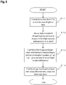
- the blood sugar level measurement device configured as described above performs operations according to a flowchart shown in Fig. 5 , the operations are described using this flowchart.
- the CPU 110 controls the driver 16, and the four LEDs 11 to 14 are driven to emit four wavelengths of light (S11).
- the four LEDs 11 to 14 are driven, in order, for a predetermined time, and light of four wavelengths ⁇ 1, ⁇ 2, ⁇ 3, and ⁇ 4 is emitted toward the fingertip 15 in a predetermined time unit.
- the blood sugar level is found using the absorbance of four wavelengths.
- statistical analysis including multivariate analysis can be used, but the present invention is not limited to this and may, for example, use machine learning.
- the following can be considered as methods using statistical analysis.
- step S11 light transmitted through the fingertip 15 is received by the sensor 17 and received light intensity information ai, bi, ci, and di is acquired (S12).
- Blood data which is the temporal change values of the absorbances corresponding to the four wavelengths, equaling ⁇ 1 + ⁇ 2 + ⁇ 3 + ⁇ 4 is found on the basis of the received light intensity information ai, bi, ci, and di (S13).
- At least one pulse is measured for each wavelength.
- the wavelengths are measured by switching as follows, ⁇ 1 nm ⁇ ⁇ 2 nm ⁇ ⁇ 3 nm ⁇ ⁇ 4 nm
- the measurement points of the four wavelengths that are separate up to this time are plotted in a single point plot.
- the wavelengths are measured by switching ⁇ 1 nm ⁇ ⁇ 2 nm ⁇ ⁇ 3 nm ⁇ ⁇ 4 nm
- the measurement points of the four wavelengths up to this time are plotted in a two point plot.
- the measurement points of the four wavelengths up to this time are plotted in a three point plot. Measurement is performed similarly thereafter to obtain a plot of a desired number of points (for example, 20).
- a peak in the pulse can be created in each of the wavelengths ⁇ 1, ⁇ 2, ⁇ 3, and ⁇ 4.
- the measurement is performed until one or more peaks in the pulse (a uniform number of peaks in each of the wavelengths, even in cases with 50 or 100 peaks, for example) can be created, and this is adopted as one set of time series data.
- One set of time series data of this kind is obtained before a meal, the next set of time series data is obtained after the meal, the next set of time series data is obtained at a predetermined time (for example, three hours) after eating, and so on to acquire time series data over a longer time scale.
- the received light intensity information ai, bi, ci, and di detected as described above includes noise, and therefore can be measured for one or more pulses.
- the matrix of expression (1) does not form a diagonal matrix.
- the intermediate parameters pA, pB, pC, and pD are found using singular value decomposition.
- the processing for repeatedly finding the optimal solution that yields the longest values for the intermediate parameters pA, pB, pC, and pD can be performed for each measurement when there are four or more measurements.
- the operation is performed by the absorbance time change value acquirer 201.
- the absorbance time change value acquirer 201 uses undetermined multipliers ⁇ 1, ⁇ 2, ⁇ 3, and ⁇ 4 to find ⁇ 1, ⁇ 2, ⁇ 3, and ⁇ 4 by the Lagrange multiplier method in the following expression (5).
- the blood sugar level is found using the calibration data of the calibration data table 202 and is output from the display device 125 (S14).
- the calibration data and the blood sugar level obtained in this way are fed back to the calibration data table 202 and the accuracy of the calibration data is increased.
- the received light intensity information ai, bi, ci, and di is acquired from the optical signal actually transmitted through the fingertip, and the blood sugar level is found by calculation using the calibration data, and therefore the magnitude of the absorbance caused by a pulse wave component can be reflected and the blood sugar level can be appropriately measured regardless of the person taking the measurement.
- one computer controls the light emission of the LEDs, acquires the received light intensity information ai, bi, ci, and di after the transmitted light is received, also acquires the blood data, and still further calculates the blood sugar level using the calibration data, but each of these may be configured to be handled by separate computers or control devices, and some operations may be grouped together and distributed across two or three computers.
- the acquisition of the blood data and also the calculation of the blood sugar level using the calibration data can be performed by locating one computer remotely, and the control of the light emission of the LEDs and acquisition of the received light intensity information ai, bi, ci, and di after the transmitted light is received can be performed at a plurality of sites. With such a system, data for a large number of people can be concentrated on a computer at one site to properly update the calibration data.
- the above embodiment describes a blood sugar level measurement device for finding a blood sugar level as the "concentration of the predetermined component in the blood," but the present invention is not limited to this. For example, it is expected that blood lipid concentration, blood cholesterol concentration, and the like can also be measured.
- the computer 100 is configured as a personal computer or the like, but the blood component concentration measurement device according to the present embodiment may be a dedicated device, and the computer 100 may be configured as a dedicated CPU.
- the data and the program necessary for processing as the blood sugar level measurement device may be stored in the main memory 111.
- a determination device for determining normality, abnormality, and a warning level on the basis of the result measured by the blood component concentration measurement device according to the present embodiment may be provided on a network, the result measured by the blood component concentration measurement device according to the present embodiment may be sent to the determination device via the network, and the determination result may be returned.
- a storage device may be provided for storing the determination result rather than the determination device, and a doctor may access the storage device by using the network to make a determination, and store the determination result in the storage device, and the blood component concentration measurement device according to the present embodiment may retrieve the result and provide a display or the like.
Landscapes
- Health & Medical Sciences (AREA)
- Life Sciences & Earth Sciences (AREA)
- Physics & Mathematics (AREA)
- Pathology (AREA)
- General Health & Medical Sciences (AREA)
- Surgery (AREA)
- Veterinary Medicine (AREA)
- Engineering & Computer Science (AREA)
- Biomedical Technology (AREA)
- Heart & Thoracic Surgery (AREA)
- Medical Informatics (AREA)
- Molecular Biology (AREA)
- Optics & Photonics (AREA)
- Animal Behavior & Ethology (AREA)
- Biophysics (AREA)
- Public Health (AREA)
- Spectroscopy & Molecular Physics (AREA)
- Emergency Medicine (AREA)
- Chemical & Material Sciences (AREA)
- Analytical Chemistry (AREA)
- Biochemistry (AREA)
- General Physics & Mathematics (AREA)
- Immunology (AREA)
- Measurement Of The Respiration, Hearing Ability, Form, And Blood Characteristics Of Living Organisms (AREA)
- Investigating Or Analysing Materials By Optical Means (AREA)
Abstract
Description
- The present invention relates to a blood component concentration measurement device.
-
Patent Literature 1 discloses a glucose concentration quantification device that accurately performs quantitative analysis of glucose concentration by taking account of a disturbance factor. The device is provided with an arithmetic calculator for performing regression analysis of glucose concentration on the basis of a signal obtained by a detector detecting near-infrared light transmitted or diffused and reflected by biological tissue or bodily fluid. The arithmetic calculator uses a continuous spectrum signal as an explanatory variable, the continuous spectrum signal being obtained by continuously measuring wavelengths in at least three adjacent regions including a first wavelength region, a second wavelength region, and a third wavelength region in a wavelength range of 1480 nm to 1880 nm, where a first harmonic of a molecule can be observed and the influence of water absorption is comparatively small, and quantifies the glucose concentration as a target variable. - The first wavelength region is 1550 nm to 1650 nm for measuring absorption derived from the OH groups of a glucose molecule, the second wavelength region is 1480 nm to 1550 nm for measuring absorption derived from an NH group of a biological component, and the third wavelength region is 1650 nm to 1880 nm for measuring absorption derived from a CH group of the biological component.
-
Patent Literature 2 discloses a highly accurate non-invasive biochemical measurement device capable of measuring information on attenuation of light in a wide range of wavelengths in a living body simultaneously at the same location. Specifically, light emitted from four light sources is introduced into four optical fibers through four lenses, and is multiplexed by a multiplexing element and introduced into one optical fiber. Further, the light is fired through a lens at the same point on a biological sample and is detected by a photodetector. - An output current of the photodetector is converted to a voltage signal by a current-voltage conversion circuit, and is converted to a digital signal by an analog-digital converter. A signal processing device controls a light source driving circuit, calculates the degree of attenuation of each wavelength due to the biological sample, and calculates the oxygen saturation, blood flow rate, and glucose concentration in the living body.
- Further,
Patent Literature 3 discloses a device capable of accurately measuring bilirubin concentration in the blood without requiring blood collection. Specifically, a first light emitter, a second light emitter, a third light emitter, and a fourth light emitter are provided, and light is emitted from the light emitters toward a measurement site. The first light emitter has a wavelength that is absorbed by reduced hemoglobin, oxidized hemoglobin, and bilirubin in the blood. The second light emitter has a wavelength that is absorbed by at least reduced hemoglobin from among reduced hemoglobin, oxidized hemoglobin, and bilirubin in the blood. - In addition, the third light emitter has a wavelength that is absorbed by at least oxidized hemoglobin from among reduced hemoglobin, oxidized hemoglobin, and bilirubin in the blood. The fourth light emitter has a wavelength that is absorbed only by water and is not absorbed by reduced hemoglobin, oxidized hemoglobin, and bilirubin in the blood. Furthermore, the device is provided with a light receiver for receiving the light emitted from the light emitters and transmitted through the measurement site and converting the light into an electric signal, and a signal generator for generating signals corresponding to a transmission quantity of each of the first light, second light, third light, and fourth light on the basis of an output signal of the light receiver. Moreover, a calculator is provided that calculates the bilirubin concentration in the blood on the basis of each signal generated by the signal generator at a first time and each signal generated by the signal generator at a second time different from the first time.
-
- Patent Literature 1:
Japanese Patent Laid-open Publication No. 2010-66280 - Patent Literature 2:
Japanese Patent Laid-open Publication No. H10-216112 - Patent Literature 3:
Japanese Patent Laid-open Publication No. H4-332535 - Although the invention of
Patent Document 1 has an advantage in that the light source is near-infrared light and a light source emitting light over a wide wavelength range is unnecessary, accurate measurement of each wavelength region is required. - In addition, in the invention of
Patent Document 2, the glucose concentration is found by applying a multivariate analysis method, but oxygen saturation, blood flow rate, and glucose concentration are obtained, and the invention does not find only the glucose concentration. - Further, the invention of
Patent Document 3 finds C(Hb): blood Hb (reduced hemoglobin) concentration, C(Hb02): blood Hb02 (oxidized hemoglobin) concentration, C(Bil): blood bilirubin concentration by using a set of three simultaneous linear equations, and the invention does not obtain a single value to be measured. - The present embodiment provides a blood component concentration measurement device capable of shortening measurement time and accurately measuring concentration of a predetermined component in blood.
- The present embodiment is provided with a four-wavelength light emitter that emits four kinds of wavelengths of light toward a predetermined site on a living body; a light receiver that receives the four kinds of wavelengths of light transmitted through the predetermined site on the living body; a received light intensity information acquirer that acquires received light intensity information for the four wavelengths on the basis of an optical signal received by the light receiver; an absorbance time change value acquirer that finds time change values of the absorbances corresponding to the four wavelengths on the basis of the received light intensity information of the four wavelengths; a calibration data table that stores calibration data for finding a predetermined component in blood based on the absorbance time change values; and a component concentration acquirer that finds the concentration of the predetermined component in the blood based on the absorbance time change values acquired by the absorbance time change value acquirer using the calibration data of the calibration data table.
-
- [
FIG. 1 ] is a configuration diagram of a blood component concentration measurement device according to an embodiment of the present invention. - [
FIG. 2 ] is a configuration diagram of a computer portion of the blood component concentration measurement device according to the embodiment of the present invention. - [
FIG. 3 ] is a configuration diagram of elements stored in an external storage device of the computer portion of the blood component concentration measurement device according to the embodiment of the present invention. - [
FIG. 4 ] is a diagram illustrating exemplary content in a calibration data table provided to the blood component concentration measurement device according to the embodiment of the present invention. - [
FIG. 5 ] is a flowchart illustrating operations of the blood component concentration measurement device according to the embodiment of the present invention. - Hereinafter, an embodiment of a blood component concentration measurement device according to the present invention is described with reference to the attached drawings. In each figure, the same components are assigned the same reference numerals and redundant descriptions thereof are omitted.
Fig. 1 shows a configuration diagram of a blood component concentration measurement device according to an embodiment of the present invention. In the present embodiment, fourLEDs - The
LEDs fingertip 15 as a predetermined site on a living body. An absorption wavelength for a blood component that is to be measured, an absorption wavelength for a blood component affecting the component to be measured, an absorption wavelength for water, and a wavelength that is not affected by the component to be measured, the blood component affecting the component to be measured, the water, and other biological components can be selected as the four wavelengths. - In the present embodiment, blood sugar level is measured as the component concentration that is to be measured. Therefore, as the four wavelengths, 1620 to 1680 nm can be selected as the absorption wavelength for sugar, which is the blood component that is to be measured; a lipid absorption wavelength of 1170 to 1230 nm can be selected as the blood component affecting the component to be measured; 1420 to 1480 nm can be selected as the absorption wavelength for water; and 1020 to 1180 nm can be selected as the wavelength that is not affected by the exemplary 1170 to 1230 nm absorbed by the lipid as the blood component affecting sugar, which is the component to be measured, by the water, and by other biological components.
- When the wavelengths are adapted to the
LEDs LED 11 can use, for example, 1020 to 1180 nm, which is not absorbed by anything, and a wavelength of light emitted from theLED 12 can use, for example, 1170 to 1230 nm, which is absorbed by the lipid. A wavelength of light emitted from theLED 13 can use, for example, 1420 to 1480 nm, which is absorbed by water, and a wavelength of light emitted from theLED 14 can use, for example, 1620 to 1680 nm, which is absorbed by sugar. - The
LEDs driver 16 that is operated by control of acomputer 100 such as a personal computer, for example, and are driven by thedriver 16 to emit light. - Light transmitted through the
fingertip 15 is received by a sensor (optical sensor) 17 as a light receiver. The light receiver receives the four wavelengths of light transmitted through the predetermined site on the living body. Thesensor 17 is connected to thecomputer 100 and an optical signal detected by thesensor 17 is captured by thecomputer 100. -
Fig. 2 illustrates a configuration of thecomputer 100 portion of a blood sugar level measurement device that is the blood component concentration measurement device according to the present embodiment (hereinafter simply referred to as the blood sugar level measurement device). Thecomputer 100 is configured around aCPU 110 and reads a program, data, or the like in a main memory 111 to run a process. TheCPU 110 is connected via a bus 112 to an external storage interface 113, an input interface 114, a display interface 115, a data output interface 116, and a data input interface 117. - An
external storage device 123 storing various data and a program theCPU 110 reads for processing as the blood sugar level measurement device is connected to the external storage interface 113. Aninput device 124 such as a keyboard and apointing device 122 such as a mouse are connected to the input interface 114. A display device 125 such as an LED display is connected to the display interface 115 and displays a required image, character, or the like. The display interface 115 may broadly be an output device interface, and an output device such as a printer can be connected to the display device 115 in addition to the display device 125. - The
driver 16 described above is connected to the data output interface 116, a drive control signal is sent from the data output interface 116 to thedriver 16 in accordance with driving data from the CPU, and a required LED from among theLEDs driver 16. Asensor 17 is connected to the data input interface 117, and the output signal of thesensor 17 is captured, and is also AD-converted and sent to theCPU 110 as received light intensity information (data). Therefore, the data input interface 117 serves as a received light intensity information acquirer that acquires received light intensity information for the four wavelengths on the basis of the optical signal received by thesensor 17 as the light receiver. - As previously described, the
external storage device 123 stores various data and the program theCPU 110 reads for processing as the blood sugar level measurement device. Specifically, an absorbance timechange value acquirer 201 realized by a program, a calibration data table 202, and a blood sugar level acquirer (in general terms, a component concentration acquirer) 203 realized by a program are provided as shown inFig. 3 . The absorbance timechange value acquirer 201 finds time change values of the absorbances corresponding to the four wavelengths on the basis of the received light intensity information of the four wavelengths acquired by the data input interface 117 as the received light intensity information acquirer. - The calibration data table 202 stores calibration data for finding a blood sugar level based on the absorbance time change values. Specifically, the calibration data table 202 is a table where numerical values (alphabet letters are numerical values) for calibration data a, b, c, d, ... are associated with absorbance time change values A, B, C, D, ... as shown in
Fig. 4 . - To begin, the calibration data table 202 obtains blood data for a fairly large number of people using a method according to the present embodiment, and also stores calibration data created on the basis of the blood data and a blood sugar level obtained by a well-known method including an invasive method, and then starts. Then, based on the blood sugar level obtained by the method of the present embodiment and the blood sugar level obtained by the well-known method including the invasive method, the calibration data can be updated by a method such as statistical analysis or machine learning, for example, and can provide a high degree of accuracy.
- The blood
sugar level acquirer 203 finds the blood sugar level based on the absorbance time change values acquired by the absorbance timechange value acquirer 201 using the calibration data of the calibration data table 202. When the absorbance timechange value acquirer 201 acquires a time change value of the absorbance as, for example, aba, a calibration data value BB is retrieved from the calibration data table 202 inFig. 3 , and a predetermined calculation (addition, multiplication, division, or the like) using the calibration data value BB is performed on the acquired time change value aba of the absorbance to find the blood sugar level. - The blood sugar level found in the above way can be converted to display data by the
CPU 110 and sent to the display interface 115. Once received, the display interface 115 can control the display device 125 to display the blood sugar level on the display device 125. - Since the blood sugar level measurement device configured as described above performs operations according to a flowchart shown in
Fig. 5 , the operations are described using this flowchart. When operation starts, theCPU 110 controls thedriver 16, and the fourLEDs 11 to 14 are driven to emit four wavelengths of light (S11). In this example, the fourLEDs 11 to 14 are driven, in order, for a predetermined time, and light of four wavelengths λ1, λ2, λ3, and λ4 is emitted toward thefingertip 15 in a predetermined time unit. - In the present embodiment, the blood sugar level is found using the absorbance of four wavelengths. As a method for doing so, statistical analysis including multivariate analysis can be used, but the present invention is not limited to this and may, for example, use machine learning. For example, the following can be considered as methods using statistical analysis. After step S11, light transmitted through the
fingertip 15 is received by thesensor 17 and received light intensity information ai, bi, ci, and di is acquired (S12). Blood data, which is the temporal change values of the absorbances corresponding to the four wavelengths, equaling η1 + η2 + η3 + η4 is found on the basis of the received light intensity information ai, bi, ci, and di (S13). - In the present embodiment, at least one pulse is measured for each wavelength. For example, when the wavelengths are measured by switching as follows, λ1 nm → λ2 nm → λ3 nm → λ4 nm, the measurement points of the four wavelengths that are separate up to this time are plotted in a single point plot. Next, when the wavelengths are measured by switching λ1 nm → λ2 nm → λ3 nm → λ4 nm, the measurement points of the four wavelengths up to this time are plotted in a two point plot. Next, when the wavelengths are measured by switching λ1 nm → λ2 nm → λ3 nm → λ4 nm, the measurement points of the four wavelengths up to this time are plotted in a three point plot. Measurement is performed similarly thereafter to obtain a plot of a desired number of points (for example, 20).
- By linking the desired number of plots described above, a peak in the pulse can be created in each of the wavelengths λ1, λ2, λ3, and λ4. The measurement is performed until one or more peaks in the pulse (a uniform number of peaks in each of the wavelengths, even in cases with 50 or 100 peaks, for example) can be created, and this is adopted as one set of time series data. One set of time series data of this kind is obtained before a meal, the next set of time series data is obtained after the meal, the next set of time series data is obtained at a predetermined time (for example, three hours) after eating, and so on to acquire time series data over a longer time scale.
- When ωλj (j = 1 to 4) is a weighting coefficient at a wavelength λj, intermediate parameters pA, pB, pC, and pD in the following expression (1) are found using singular value decomposition, and absorbance time change values are found on the basis of the intermediate parameters pA, pB, pC, and pD obtained.
[Equation 1]
- Expression (1) is equivalent to the following expression (2).
[Equation 2]
- Of the intermediate parameters in expression (2), above, the parameter that corresponds to the time series data at a given time t1 in the previously described time series data is represented by the following expression (3):
[Equation 3]
[Equation 4]
- The received light intensity information ai, bi, ci, and di detected as described above includes noise, and therefore can be measured for one or more pulses. When measurement is performed two or more times, the matrix of expression (1) does not form a diagonal matrix. Given this, in the present embodiment, the intermediate parameters pA, pB, pC, and pD are found using singular value decomposition. The processing for repeatedly finding the optimal solution that yields the longest values for the intermediate parameters pA, pB, pC, and pD can be performed for each measurement when there are four or more measurements. The operation is performed by the absorbance time
change value acquirer 201. - Further, when the absorbance time change value is blood data and the blood data equals η1 + η2 + η3 + η4, the absorbance time
change value acquirer 201 uses undetermined multipliers χ1, χ2, χ3, and χ4 to find η1, η2, η3, and η4 by the Lagrange multiplier method in the following expression (5).
[Equation 5]
- As described above, when the blood data equaling η1 + η2 + η3 + η4 is found, the blood sugar level is found using the calibration data of the calibration data table 202 and is output from the display device 125 (S14).
- The calibration data and the blood sugar level obtained in this way are fed back to the calibration data table 202 and the accuracy of the calibration data is increased. In this way, the received light intensity information ai, bi, ci, and di is acquired from the optical signal actually transmitted through the fingertip, and the blood sugar level is found by calculation using the calibration data, and therefore the magnitude of the absorbance caused by a pulse wave component can be reflected and the blood sugar level can be appropriately measured regardless of the person taking the measurement.
- In the present embodiment, one computer controls the light emission of the LEDs, acquires the received light intensity information ai, bi, ci, and di after the transmitted light is received, also acquires the blood data, and still further calculates the blood sugar level using the calibration data, but each of these may be configured to be handled by separate computers or control devices, and some operations may be grouped together and distributed across two or three computers. In this case, the acquisition of the blood data and also the calculation of the blood sugar level using the calibration data can be performed by locating one computer remotely, and the control of the light emission of the LEDs and acquisition of the received light intensity information ai, bi, ci, and di after the transmitted light is received can be performed at a plurality of sites. With such a system, data for a large number of people can be concentrated on a computer at one site to properly update the calibration data.
- The above embodiment describes a blood sugar level measurement device for finding a blood sugar level as the "concentration of the predetermined component in the blood," but the present invention is not limited to this. For example, it is expected that blood lipid concentration, blood cholesterol concentration, and the like can also be measured.
- Additionally, in the above description, the
computer 100 is configured as a personal computer or the like, but the blood component concentration measurement device according to the present embodiment may be a dedicated device, and thecomputer 100 may be configured as a dedicated CPU. In this case, the data and the program necessary for processing as the blood sugar level measurement device may be stored in the main memory 111. - In addition, a determination device for determining normality, abnormality, and a warning level on the basis of the result measured by the blood component concentration measurement device according to the present embodiment may be provided on a network, the result measured by the blood component concentration measurement device according to the present embodiment may be sent to the determination device via the network, and the determination result may be returned. Needless to say, a storage device may be provided for storing the determination result rather than the determination device, and a doctor may access the storage device by using the network to make a determination, and store the determination result in the storage device, and the blood component concentration measurement device according to the present embodiment may retrieve the result and provide a display or the like.
-
- 11 to 14
- LED
- 15
- Fingertip
- 16
- Driver
- 17
- Sensor
- 100
- Computer
- 110
- CPU
- 111
- Main memory
- 112
- Bus
- 113
- External storage interface
- 114
- Input interface
- 115
- Display interface
- 116
- Data output interface
- 117
- Data input interface
- 122
- Pointing device
- 123
- External storage device
- 124
- Input device
- 125
- Display device
- 201
- Absorbance time change value acquirer
- 202
- Calibration data table
- 203
- Blood sugar level acquirer (component concentration acquirer)
Claims (5)
- A blood component concentration measurement device comprising:a four-wavelength light emitter that emits four kinds of wavelengths of light toward a predetermined site on a living body;a light receiver that receives the four kinds of wavelengths of light transmitted through the predetermined site on the living body;a received light intensity information acquirer that acquires received light intensity information for the four wavelengths on the basis of an optical signal received by the light receiver;an absorbance time change value acquirer that finds time change values of absorbances corresponding to the four wavelengths on the basis of the received light intensity information of the four wavelengths;a calibration data table that stores calibration data for finding a predetermined component in blood based on the absorbance time change values; anda component concentration acquirer that finds the concentration of the predetermined component in the blood based on the absorbance time change values acquired by the absorbance time change value acquirer using the calibration data of the calibration data table.
- The blood component concentration measurement device according to claim 1, wherein the absorbance time change value acquirer finds the time change values of the absorbances corresponding to the four wavelengths on the basis of a plurality of continuous received light intensity information that is acquired at a fixed time interval by the received light intensity information acquirer.
- The blood component concentration measurement device according to claim 1 or 2,
wherein the absorbance time change value acquirer finds the time change values of the absorbances corresponding to the four wavelengths on the basis of at least one acquisition of the continuous received light intensity information that is acquired at a fixed time interval by the received light intensity information acquirer. - The blood component concentration measurement device according to any one of claims 1 to 3, wherein an absorption wavelength for a blood component that is to be measured, an absorption wavelength for a blood component affecting the component to be measured, an absorption wavelength for water, and a wavelength that is not affected by the component to be measured, the blood component, the water, and other biological components are selected as the four wavelengths.
- The blood component concentration measurement device according to claim 4, wherein 1620 to 1680 nm is selected as an absorption wavelength for the blood component that is to be measured; a lipid absorption wavelength of 1170 to 1230 nm is selected as the blood component affecting the component to be measured; 1420 to 1480 nm is selected as the absorption wavelength for water; and 1020 to 1180 nm is selected as the wavelength that is not affected by the component to be measured, the blood component, the water, and other biological components.
Applications Claiming Priority (2)
| Application Number | Priority Date | Filing Date | Title |
|---|---|---|---|
| JP2019203020A JP7425436B2 (en) | 2019-11-08 | 2019-11-08 | Blood component concentration measuring device |
| PCT/JP2020/041394 WO2021090891A1 (en) | 2019-11-08 | 2020-11-05 | Blood-component-concentration measurement device |
Publications (3)
| Publication Number | Publication Date |
|---|---|
| EP4056115A1 true EP4056115A1 (en) | 2022-09-14 |
| EP4056115A4 EP4056115A4 (en) | 2023-11-15 |
| EP4056115B1 EP4056115B1 (en) | 2025-01-22 |
Family
ID=75848571
Family Applications (1)
| Application Number | Title | Priority Date | Filing Date |
|---|---|---|---|
| EP20885303.6A Active EP4056115B1 (en) | 2019-11-08 | 2020-11-05 | Blood-component-concentration measurement device |
Country Status (6)
| Country | Link |
|---|---|
| US (1) | US12533057B2 (en) |
| EP (1) | EP4056115B1 (en) |
| JP (1) | JP7425436B2 (en) |
| KR (1) | KR102851548B1 (en) |
| CN (1) | CN114599281B (en) |
| WO (1) | WO2021090891A1 (en) |
Family Cites Families (18)
| Publication number | Priority date | Publication date | Assignee | Title |
|---|---|---|---|---|
| JPH04332535A (en) | 1991-05-07 | 1992-11-19 | Minolta Camera Co Ltd | Instrument for measuring concentration of bilirubin in blood |
| JPH0956702A (en) * | 1995-08-18 | 1997-03-04 | Minolta Co Ltd | Noninvasive measuring apparatus for components in blood |
| JPH10216112A (en) | 1997-02-04 | 1998-08-18 | Hitachi Ltd | Non-invasive biochemical measurement device |
| TW352335B (en) | 1997-03-25 | 1999-02-11 | Matsushita Electric Works Ltd | Method of determining a glucose concentration in a target by using near-infrared spectroscopy |
| GB2329015B (en) * | 1997-09-05 | 2002-02-13 | Samsung Electronics Co Ltd | Method and device for noninvasive measurement of concentrations of blood components |
| WO1999049937A1 (en) * | 1998-03-27 | 1999-10-07 | The General Hospital Corporation | Method and apparatus for the selective targeting of lipid-rich tissues |
| US7167734B2 (en) * | 2001-04-13 | 2007-01-23 | Abbott Laboratories | Method for optical measurements of tissue to determine disease state or concentration of an analyte |
| KR100389906B1 (en) * | 2001-05-09 | 2003-07-04 | 삼성전자주식회사 | Apparatus and method for measuring concentration of component in target material |
| JP2008289807A (en) * | 2007-05-28 | 2008-12-04 | Panasonic Electric Works Co Ltd | Sensing device for biological surface tissue |
| JP2014016235A (en) * | 2012-07-09 | 2014-01-30 | Seiko Epson Corp | Apparatus for estimating optical absorption coefficient distribution, apparatus for measuring concentration and method for controlling apparatus for estimating optical absorption coefficient distribution |
| JP2014018478A (en) * | 2012-07-19 | 2014-02-03 | Panasonic Corp | Method and device for blood sugar level measurement |
| JP2015205152A (en) * | 2014-04-07 | 2015-11-19 | セイコーエプソン株式会社 | Biological information acquisition device, and biological information acquisition method |
| JP6606082B2 (en) * | 2014-09-05 | 2019-11-13 | Phcホールディングス株式会社 | Glucose concentration determination method and glucose concentration measurement device |
| WO2016191307A1 (en) * | 2015-05-22 | 2016-12-01 | Cercacor Laboratories, Inc. | Non-invasive optical physiological differential pathlength sensor |
| JP2017060640A (en) * | 2015-09-25 | 2017-03-30 | セイコーエプソン株式会社 | Determination method and determination device |
| JP6846152B2 (en) * | 2016-10-03 | 2021-03-24 | 浜松ホトニクス株式会社 | Blood glucose measuring device, blood glucose calculation method and blood glucose calculation program |
| US20190282139A1 (en) * | 2016-11-04 | 2019-09-19 | Kowa Company, Ltd. | In-blood component measurement method, in-blood component measurement device and in-blood component measurement program |
| KR102534002B1 (en) | 2018-02-14 | 2023-05-19 | 삼성전자주식회사 | Electronic device including a sensor for sensing biometric information using a plurality of receiving units and control method thereof |
-
2019
- 2019-11-08 JP JP2019203020A patent/JP7425436B2/en active Active
-
2020
- 2020-11-05 CN CN202080075430.3A patent/CN114599281B/en active Active
- 2020-11-05 US US17/771,725 patent/US12533057B2/en active Active
- 2020-11-05 WO PCT/JP2020/041394 patent/WO2021090891A1/en not_active Ceased
- 2020-11-05 EP EP20885303.6A patent/EP4056115B1/en active Active
- 2020-11-05 KR KR1020227015356A patent/KR102851548B1/en active Active
Also Published As
| Publication number | Publication date |
|---|---|
| KR102851548B1 (en) | 2025-08-28 |
| CN114599281B (en) | 2025-06-03 |
| EP4056115A4 (en) | 2023-11-15 |
| US12533057B2 (en) | 2026-01-27 |
| KR20220074964A (en) | 2022-06-03 |
| JP2021074258A (en) | 2021-05-20 |
| EP4056115B1 (en) | 2025-01-22 |
| JP7425436B2 (en) | 2024-01-31 |
| US20220369959A1 (en) | 2022-11-24 |
| WO2021090891A1 (en) | 2021-05-14 |
| CN114599281A (en) | 2022-06-07 |
Similar Documents
| Publication | Publication Date | Title |
|---|---|---|
| US7899506B2 (en) | Composite spectral measurement method and its spectral detection instrument | |
| US4854699A (en) | Backscatter oximeter | |
| KR102498119B1 (en) | Compact spectrometer system for non-invasive measurement of absorption and transmission spectra in biological tissue samples | |
| EP1327418B1 (en) | Organism optical measurement instrument | |
| EP0290272B1 (en) | Examination apparatus for measuring oxygenation | |
| JPH1043166A (en) | Optimum diagnostic point search apparatus for blood-free diagnosis of blood components and blood-free diagnostic apparatus using the same | |
| EP0497021A1 (en) | Oximeter with monitor | |
| WO2003079900A1 (en) | Noninvasive blood component value measuring instrument and method | |
| AU5826694A (en) | Low cost means for increasing measurement sensitivity in led/ired near-infrared instruments | |
| DE19840452A1 (en) | Method and device for the non-invasive measurement of concentrations of blood components | |
| HK1053045A1 (en) | Non-invasive measurement of skin bilirubin level | |
| KR20200020341A (en) | Apparatus and method for bio-signal analysis using machine learning | |
| US20250251282A1 (en) | Methods For Implementing Standardised Time Domain Diffuse Optical Spectroscopy In Wearables/Portables | |
| EP3815608B1 (en) | Apparatus and method for estimating concentration of analyte | |
| JP6220065B2 (en) | Biological light measurement device and method | |
| EP0290273A1 (en) | Examination apparatus for measuring oxygenation | |
| JPH06245938A (en) | Optical measuring instrument | |
| EP4056115B1 (en) | Blood-component-concentration measurement device | |
| KR102166444B1 (en) | Non invasive glucose meter using nir spectroscopy and method of measuring glucose meter using the same | |
| CN120514351A (en) | A health detection device and method based on laser light source | |
| Jahagirdar et al. | Design and algorithms of the device to predict blood glucose level based on saliva sample using machine learning | |
| KR20070055614A (en) | Non-invasive measuring device of blood sugar level | |
| US20250127438A1 (en) | Fiber coupled network of sensors for near-infrared spectroscopy based tissue oxygenation | |
| US20240245328A1 (en) | Near-infrared spectroscopy based handheld tissue oxygenation scanner | |
| JP2015150186A5 (en) |
Legal Events
| Date | Code | Title | Description |
|---|---|---|---|
| STAA | Information on the status of an ep patent application or granted ep patent |
Free format text: STATUS: THE INTERNATIONAL PUBLICATION HAS BEEN MADE |
|
| PUAI | Public reference made under article 153(3) epc to a published international application that has entered the european phase |
Free format text: ORIGINAL CODE: 0009012 |
|
| STAA | Information on the status of an ep patent application or granted ep patent |
Free format text: STATUS: REQUEST FOR EXAMINATION WAS MADE |
|
| 17P | Request for examination filed |
Effective date: 20220513 |
|
| AK | Designated contracting states |
Kind code of ref document: A1 Designated state(s): AL AT BE BG CH CY CZ DE DK EE ES FI FR GB GR HR HU IE IS IT LI LT LU LV MC MK MT NL NO PL PT RO RS SE SI SK SM TR |
|
| DAV | Request for validation of the european patent (deleted) | ||
| DAX | Request for extension of the european patent (deleted) | ||
| A4 | Supplementary search report drawn up and despatched |
Effective date: 20231013 |
|
| RIC1 | Information provided on ipc code assigned before grant |
Ipc: A61B 5/1455 20060101AFI20231009BHEP |
|
| GRAP | Despatch of communication of intention to grant a patent |
Free format text: ORIGINAL CODE: EPIDOSNIGR1 |
|
| STAA | Information on the status of an ep patent application or granted ep patent |
Free format text: STATUS: GRANT OF PATENT IS INTENDED |
|
| INTG | Intention to grant announced |
Effective date: 20240926 |
|
| GRAS | Grant fee paid |
Free format text: ORIGINAL CODE: EPIDOSNIGR3 |
|
| GRAA | (expected) grant |
Free format text: ORIGINAL CODE: 0009210 |
|
| STAA | Information on the status of an ep patent application or granted ep patent |
Free format text: STATUS: THE PATENT HAS BEEN GRANTED |
|
| AK | Designated contracting states |
Kind code of ref document: B1 Designated state(s): AL AT BE BG CH CY CZ DE DK EE ES FI FR GB GR HR HU IE IS IT LI LT LU LV MC MK MT NL NO PL PT RO RS SE SI SK SM TR |
|
| REG | Reference to a national code |
Ref country code: GB Ref legal event code: FG4D |
|
| REG | Reference to a national code |
Ref country code: CH Ref legal event code: EP |
|
| REG | Reference to a national code |
Ref country code: IE Ref legal event code: FG4D |
|
| REG | Reference to a national code |
Ref country code: DE Ref legal event code: R096 Ref document number: 602020045339 Country of ref document: DE |
|
| REG | Reference to a national code |
Ref country code: NL Ref legal event code: MP Effective date: 20250122 |
|
| PG25 | Lapsed in a contracting state [announced via postgrant information from national office to epo] |
Ref country code: NL Free format text: LAPSE BECAUSE OF FAILURE TO SUBMIT A TRANSLATION OF THE DESCRIPTION OR TO PAY THE FEE WITHIN THE PRESCRIBED TIME-LIMIT Effective date: 20250122 |
|
| PG25 | Lapsed in a contracting state [announced via postgrant information from national office to epo] |
Ref country code: RS Free format text: LAPSE BECAUSE OF FAILURE TO SUBMIT A TRANSLATION OF THE DESCRIPTION OR TO PAY THE FEE WITHIN THE PRESCRIBED TIME-LIMIT Effective date: 20250422 |
|
| PG25 | Lapsed in a contracting state [announced via postgrant information from national office to epo] |
Ref country code: FI Free format text: LAPSE BECAUSE OF FAILURE TO SUBMIT A TRANSLATION OF THE DESCRIPTION OR TO PAY THE FEE WITHIN THE PRESCRIBED TIME-LIMIT Effective date: 20250122 |
|
| PG25 | Lapsed in a contracting state [announced via postgrant information from national office to epo] |
Ref country code: PL Free format text: LAPSE BECAUSE OF FAILURE TO SUBMIT A TRANSLATION OF THE DESCRIPTION OR TO PAY THE FEE WITHIN THE PRESCRIBED TIME-LIMIT Effective date: 20250122 |
|
| PG25 | Lapsed in a contracting state [announced via postgrant information from national office to epo] |
Ref country code: ES Free format text: LAPSE BECAUSE OF FAILURE TO SUBMIT A TRANSLATION OF THE DESCRIPTION OR TO PAY THE FEE WITHIN THE PRESCRIBED TIME-LIMIT Effective date: 20250122 |
|
| REG | Reference to a national code |
Ref country code: LT Ref legal event code: MG9D |
|
| PG25 | Lapsed in a contracting state [announced via postgrant information from national office to epo] |
Ref country code: NO Free format text: LAPSE BECAUSE OF FAILURE TO SUBMIT A TRANSLATION OF THE DESCRIPTION OR TO PAY THE FEE WITHIN THE PRESCRIBED TIME-LIMIT Effective date: 20250422 Ref country code: IS Free format text: LAPSE BECAUSE OF FAILURE TO SUBMIT A TRANSLATION OF THE DESCRIPTION OR TO PAY THE FEE WITHIN THE PRESCRIBED TIME-LIMIT Effective date: 20250522 |
|
| REG | Reference to a national code |
Ref country code: AT Ref legal event code: MK05 Ref document number: 1760824 Country of ref document: AT Kind code of ref document: T Effective date: 20250122 |
|
| PG25 | Lapsed in a contracting state [announced via postgrant information from national office to epo] |
Ref country code: HR Free format text: LAPSE BECAUSE OF FAILURE TO SUBMIT A TRANSLATION OF THE DESCRIPTION OR TO PAY THE FEE WITHIN THE PRESCRIBED TIME-LIMIT Effective date: 20250122 |
|
| PG25 | Lapsed in a contracting state [announced via postgrant information from national office to epo] |
Ref country code: LV Free format text: LAPSE BECAUSE OF FAILURE TO SUBMIT A TRANSLATION OF THE DESCRIPTION OR TO PAY THE FEE WITHIN THE PRESCRIBED TIME-LIMIT Effective date: 20250122 Ref country code: PT Free format text: LAPSE BECAUSE OF FAILURE TO SUBMIT A TRANSLATION OF THE DESCRIPTION OR TO PAY THE FEE WITHIN THE PRESCRIBED TIME-LIMIT Effective date: 20250522 |
|
| PG25 | Lapsed in a contracting state [announced via postgrant information from national office to epo] |
Ref country code: GR Free format text: LAPSE BECAUSE OF FAILURE TO SUBMIT A TRANSLATION OF THE DESCRIPTION OR TO PAY THE FEE WITHIN THE PRESCRIBED TIME-LIMIT Effective date: 20250423 Ref country code: BG Free format text: LAPSE BECAUSE OF FAILURE TO SUBMIT A TRANSLATION OF THE DESCRIPTION OR TO PAY THE FEE WITHIN THE PRESCRIBED TIME-LIMIT Effective date: 20250122 |
|
| PG25 | Lapsed in a contracting state [announced via postgrant information from national office to epo] |
Ref country code: AT Free format text: LAPSE BECAUSE OF FAILURE TO SUBMIT A TRANSLATION OF THE DESCRIPTION OR TO PAY THE FEE WITHIN THE PRESCRIBED TIME-LIMIT Effective date: 20250122 |
|
| PG25 | Lapsed in a contracting state [announced via postgrant information from national office to epo] |
Ref country code: SE Free format text: LAPSE BECAUSE OF FAILURE TO SUBMIT A TRANSLATION OF THE DESCRIPTION OR TO PAY THE FEE WITHIN THE PRESCRIBED TIME-LIMIT Effective date: 20250122 |
|
| PG25 | Lapsed in a contracting state [announced via postgrant information from national office to epo] |
Ref country code: SM Free format text: LAPSE BECAUSE OF FAILURE TO SUBMIT A TRANSLATION OF THE DESCRIPTION OR TO PAY THE FEE WITHIN THE PRESCRIBED TIME-LIMIT Effective date: 20250122 |
|
| PG25 | Lapsed in a contracting state [announced via postgrant information from national office to epo] |
Ref country code: DK Free format text: LAPSE BECAUSE OF FAILURE TO SUBMIT A TRANSLATION OF THE DESCRIPTION OR TO PAY THE FEE WITHIN THE PRESCRIBED TIME-LIMIT Effective date: 20250122 |
|
| PG25 | Lapsed in a contracting state [announced via postgrant information from national office to epo] |
Ref country code: IT Free format text: LAPSE BECAUSE OF FAILURE TO SUBMIT A TRANSLATION OF THE DESCRIPTION OR TO PAY THE FEE WITHIN THE PRESCRIBED TIME-LIMIT Effective date: 20250122 |
|
| PG25 | Lapsed in a contracting state [announced via postgrant information from national office to epo] |
Ref country code: CZ Free format text: LAPSE BECAUSE OF FAILURE TO SUBMIT A TRANSLATION OF THE DESCRIPTION OR TO PAY THE FEE WITHIN THE PRESCRIBED TIME-LIMIT Effective date: 20250122 Ref country code: EE Free format text: LAPSE BECAUSE OF FAILURE TO SUBMIT A TRANSLATION OF THE DESCRIPTION OR TO PAY THE FEE WITHIN THE PRESCRIBED TIME-LIMIT Effective date: 20250122 |
|
| REG | Reference to a national code |
Ref country code: DE Ref legal event code: R097 Ref document number: 602020045339 Country of ref document: DE |
|
| PG25 | Lapsed in a contracting state [announced via postgrant information from national office to epo] |
Ref country code: RO Free format text: LAPSE BECAUSE OF FAILURE TO SUBMIT A TRANSLATION OF THE DESCRIPTION OR TO PAY THE FEE WITHIN THE PRESCRIBED TIME-LIMIT Effective date: 20250122 |
|
| PG25 | Lapsed in a contracting state [announced via postgrant information from national office to epo] |
Ref country code: SK Free format text: LAPSE BECAUSE OF FAILURE TO SUBMIT A TRANSLATION OF THE DESCRIPTION OR TO PAY THE FEE WITHIN THE PRESCRIBED TIME-LIMIT Effective date: 20250122 |
|
| PLBE | No opposition filed within time limit |
Free format text: ORIGINAL CODE: 0009261 |
|
| STAA | Information on the status of an ep patent application or granted ep patent |
Free format text: STATUS: NO OPPOSITION FILED WITHIN TIME LIMIT |
|
| 26N | No opposition filed |
Effective date: 20251023 |
|
| PGFP | Annual fee paid to national office [announced via postgrant information from national office to epo] |
Ref country code: DE Payment date: 20251119 Year of fee payment: 6 |
|
| PGFP | Annual fee paid to national office [announced via postgrant information from national office to epo] |
Ref country code: GB Payment date: 20251121 Year of fee payment: 6 |
|
| PGFP | Annual fee paid to national office [announced via postgrant information from national office to epo] |
Ref country code: FR Payment date: 20251126 Year of fee payment: 6 |