EP4056110B1 - Method and apparatus for calculating an adjusted blood flow velocity in largest congestion state on basis of microcirculation resistance index - Google Patents
Method and apparatus for calculating an adjusted blood flow velocity in largest congestion state on basis of microcirculation resistance index Download PDFInfo
- Publication number
- EP4056110B1 EP4056110B1 EP19952100.6A EP19952100A EP4056110B1 EP 4056110 B1 EP4056110 B1 EP 4056110B1 EP 19952100 A EP19952100 A EP 19952100A EP 4056110 B1 EP4056110 B1 EP 4056110B1
- Authority
- EP
- European Patent Office
- Prior art keywords
- flow velocity
- blood flow
- blood vessel
- index
- centerline
- Prior art date
- Legal status (The legal status is an assumption and is not a legal conclusion. Google has not performed a legal analysis and makes no representation as to the accuracy of the status listed.)
- Active
Links
Images



Classifications
-
- G—PHYSICS
- G06—COMPUTING OR CALCULATING; COUNTING
- G06T—IMAGE DATA PROCESSING OR GENERATION, IN GENERAL
- G06T7/00—Image analysis
- G06T7/0002—Inspection of images, e.g. flaw detection
- G06T7/0012—Biomedical image inspection
- G06T7/0014—Biomedical image inspection using an image reference approach
- G06T7/0016—Biomedical image inspection using an image reference approach involving temporal comparison
-
- A—HUMAN NECESSITIES
- A61—MEDICAL OR VETERINARY SCIENCE; HYGIENE
- A61B—DIAGNOSIS; SURGERY; IDENTIFICATION
- A61B34/00—Computer-aided surgery; Manipulators or robots specially adapted for use in surgery
- A61B34/10—Computer-aided planning, simulation or modelling of surgical operations
-
- A—HUMAN NECESSITIES
- A61—MEDICAL OR VETERINARY SCIENCE; HYGIENE
- A61B—DIAGNOSIS; SURGERY; IDENTIFICATION
- A61B5/00—Measuring for diagnostic purposes; Identification of persons
- A61B5/0033—Features or image-related aspects of imaging apparatus, e.g. for MRI, optical tomography or impedance tomography apparatus; Arrangements of imaging apparatus in a room
-
- A—HUMAN NECESSITIES
- A61—MEDICAL OR VETERINARY SCIENCE; HYGIENE
- A61B—DIAGNOSIS; SURGERY; IDENTIFICATION
- A61B5/00—Measuring for diagnostic purposes; Identification of persons
- A61B5/02—Detecting, measuring or recording for evaluating the cardiovascular system, e.g. pulse, heart rate, blood pressure or blood flow
- A61B5/02028—Determining haemodynamic parameters not otherwise provided for, e.g. cardiac contractility or left ventricular ejection fraction
-
- A—HUMAN NECESSITIES
- A61—MEDICAL OR VETERINARY SCIENCE; HYGIENE
- A61B—DIAGNOSIS; SURGERY; IDENTIFICATION
- A61B5/00—Measuring for diagnostic purposes; Identification of persons
- A61B5/02—Detecting, measuring or recording for evaluating the cardiovascular system, e.g. pulse, heart rate, blood pressure or blood flow
- A61B5/026—Measuring blood flow
-
- A—HUMAN NECESSITIES
- A61—MEDICAL OR VETERINARY SCIENCE; HYGIENE
- A61B—DIAGNOSIS; SURGERY; IDENTIFICATION
- A61B5/00—Measuring for diagnostic purposes; Identification of persons
- A61B5/02—Detecting, measuring or recording for evaluating the cardiovascular system, e.g. pulse, heart rate, blood pressure or blood flow
- A61B5/026—Measuring blood flow
- A61B5/0275—Measuring blood flow using tracers, e.g. dye dilution
-
- A—HUMAN NECESSITIES
- A61—MEDICAL OR VETERINARY SCIENCE; HYGIENE
- A61B—DIAGNOSIS; SURGERY; IDENTIFICATION
- A61B5/00—Measuring for diagnostic purposes; Identification of persons
- A61B5/103—Measuring devices for testing the shape, pattern, colour, size or movement of the body or parts thereof, for diagnostic purposes
- A61B5/107—Measuring physical dimensions, e.g. size of the entire body or parts thereof
- A61B5/1072—Measuring physical dimensions, e.g. size of the entire body or parts thereof measuring distances on the body, e.g. measuring length, height or thickness
-
- A—HUMAN NECESSITIES
- A61—MEDICAL OR VETERINARY SCIENCE; HYGIENE
- A61B—DIAGNOSIS; SURGERY; IDENTIFICATION
- A61B5/00—Measuring for diagnostic purposes; Identification of persons
- A61B5/48—Other medical applications
- A61B5/4887—Locating particular structures in or on the body
- A61B5/489—Blood vessels
-
- G—PHYSICS
- G06—COMPUTING OR CALCULATING; COUNTING
- G06T—IMAGE DATA PROCESSING OR GENERATION, IN GENERAL
- G06T17/00—Three-dimensional [3D] modelling for computer graphics
-
- G—PHYSICS
- G06—COMPUTING OR CALCULATING; COUNTING
- G06T—IMAGE DATA PROCESSING OR GENERATION, IN GENERAL
- G06T7/00—Image analysis
- G06T7/10—Segmentation; Edge detection
- G06T7/11—Region-based segmentation
-
- G—PHYSICS
- G06—COMPUTING OR CALCULATING; COUNTING
- G06T—IMAGE DATA PROCESSING OR GENERATION, IN GENERAL
- G06T7/00—Image analysis
- G06T7/10—Segmentation; Edge detection
- G06T7/13—Edge detection
-
- A—HUMAN NECESSITIES
- A61—MEDICAL OR VETERINARY SCIENCE; HYGIENE
- A61B—DIAGNOSIS; SURGERY; IDENTIFICATION
- A61B34/00—Computer-aided surgery; Manipulators or robots specially adapted for use in surgery
- A61B34/10—Computer-aided planning, simulation or modelling of surgical operations
- A61B2034/101—Computer-aided simulation of surgical operations
- A61B2034/105—Modelling of the patient, e.g. for ligaments or bones
-
- A—HUMAN NECESSITIES
- A61—MEDICAL OR VETERINARY SCIENCE; HYGIENE
- A61B—DIAGNOSIS; SURGERY; IDENTIFICATION
- A61B2576/00—Medical imaging apparatus involving image processing or analysis
-
- G—PHYSICS
- G06—COMPUTING OR CALCULATING; COUNTING
- G06T—IMAGE DATA PROCESSING OR GENERATION, IN GENERAL
- G06T2207/00—Indexing scheme for image analysis or image enhancement
- G06T2207/30—Subject of image; Context of image processing
- G06T2207/30004—Biomedical image processing
- G06T2207/30101—Blood vessel; Artery; Vein; Vascular
- G06T2207/30104—Vascular flow; Blood flow; Perfusion
-
- G—PHYSICS
- G06—COMPUTING OR CALCULATING; COUNTING
- G06T—IMAGE DATA PROCESSING OR GENERATION, IN GENERAL
- G06T2207/00—Indexing scheme for image analysis or image enhancement
- G06T2207/30—Subject of image; Context of image processing
- G06T2207/30172—Centreline of tubular or elongated structure
-
- G—PHYSICS
- G06—COMPUTING OR CALCULATING; COUNTING
- G06T—IMAGE DATA PROCESSING OR GENERATION, IN GENERAL
- G06T2210/00—Indexing scheme for image generation or computer graphics
- G06T2210/41—Medical
Definitions
- the present disclosure relates to the field of coronary artery technology, and in particular, to a method and an apparatus for calculating an adjusted blood flow velocity in maximum hyperemia state based on index for microcirculatory resistance, a coronary artery analysis system and a computer storage medium.
- cardiovascular diseases According to the statistics of the World Health Organization, cardiovascular diseases have become a "leading killer" of human health. In recent years, the analysis of the physiological and pathological behaviors of cardiovascular diseases using hemodynamics has also become a very important means of diagnosis of the cardiovascular diseases.
- Blood flow quantity and flow velocity are very important parameters of hemodynamics. How to measure the blood flow quantity and flow velocity accurately and conveniently has become the focus of many researchers.
- CN 110 384 494 A and CN 108 550 189 A disclose devices and methods for calculating the blood flow velocity.
- the present disclosure provides a method and an apparatus for calculating an adjusted blood flow velocity in maximum hyperemia state based on index for microcirculatory resistance, a coronary artery analysis system and a computer storage medium, so as to solve the problem of how to obtain a more targeted, individualized blood flow velocity in the maximum hyperemia state according to individualized differences.
- the present disclosure provides a method for calculating an adjusted blood flow velocity in maximum hyperemia state based on index for microcirculatory resistance, comprising:
- ⁇ h z ⁇ ⁇ + x
- v h the blood flow velocity in the maximum hyperemia state
- v an average blood flow velocity in a heartbeat cycle area
- z is a constant in the range of 1 to 3
- a manner for acquiring an index for microcirculatory resistance iFMR during a diastolic phase according to a blood flow velocity v, an aortic pressure waveform, and an physiological parameter comprises:
- the influence parameter k a ⁇ b, wherein a represents a characteristic value of diabetes, b represents a characteristic value of hypertension, and c represents gender.
- a manner for acquiring a blood flow velocity comprises:
- a manner for extracting a blood vessel segment of interest from the group of two-dimensional coronary artery angiogram images comprises:
- a manner for extracting the centerline of the blood vessel segment comprises:
- a manner for determining a difference in time taken for a contrast agent flowing through the blood vessel segment in any two frames of the two-dimensional coronary artery angiogram images with the difference being ⁇ t , and determining a difference in centerline length of a sub-segment of the blood vessel segment through which the contrast agent flows in the two frames of two-dimensional coronary artery angiogram image with the difference being ⁇ L , and solving the blood flow velocity according to the ratio of ⁇ L to ⁇ t comprises:
- a manner for determining a difference in time taken a contrast agent flowing through the blood vessel segment in any two frames of the two-dimensional coronary artery angiogram images with the difference being ⁇ t , and determining a difference in centerline length of a sub-segment of the blood vessel segment through which the contrast agent flows in the two frames of two-dimensional coronary artery angiogram image with the difference being ⁇ L , and solving the blood flow velocity according to the ratio of ⁇ L to ⁇ t comprises:
- the method further comprises:
- a manner for solving the blood flow velocity according to the ratio of ⁇ L to ⁇ t comprises:
- the present disclosure provides an apparatus for calculating an adjusted blood flow velocity in maximum hyperemia state based on index for microcirculatory resistance, used for the above method for adjusting blood flow velocity in maximum hyperemia state based on index for microcirculatory resistance, comprising: a blood flow velocity acquisition unit , an aortic pressure waveform acquisition unit, a physiological parameter acquisition unit, an unit of index for microcirculatory resistance during diastolic phase and an adjustment parameter unit; the unit of index for microcirculatory resistance during diastolic phase is connected with the blood flow velocity acquisition unit, the aortic pressure waveform acquisition unit and the physiological parameter acquisition unit;
- the above apparatus for calculating an adjusted blood flow velocity in maximum hyperemia state based on index for microcirculatory resistance further comprises: an image reading unit, a blood vessel segment extraction unit, and a centerline extraction unit connected in sequence, a time difference unit and the physiological parameter acquisition unit both connected to the image reading unit, and the blood flow velocity acquisition unit that respectively connected with the time difference unit and a centerline difference unit, respectively; the centerline difference unit is connected with the centerline extraction unit;
- the above apparatus for calculating an adjusted blood flow velocity in maximum hyperemia state based on index of microcirculatory resistance further comprises: a blood vessel skeleton extraction unit and a three-dimensional blood vessel reconstruction unit, both connected to the image reading unit, a contour line extraction unit connected to the blood vessel skeleton extraction unit, the three-dimensional blood vessel reconstruction unit being connected with the physiological parameter acquisition unit, the centerline extraction unit and the contour line extraction unit;
- the present disclosure provides a coronary artery analysis system, comprising: the apparatus for calculating an adjusted blood flow velocity in maximum hyperemia state based on index for microcirculatory resistance according to any one of the above.
- the present disclosure provides a computer storage medium having stored thereon a computer program to be executed by a processor, the above method for calculating an adjusted blood flow velocity in maximum hyperemia state based on index for microcirculatory resistance is implemented when the computer program is executed by the processor.
- an index for microcirculatory resistance iFMR during a diastolic phase is acquired according to a blood flow velocity v, an aortic pressure waveform, and an physiological parameter; then an adjustment parameter is obtained by comparing iFMR with K, where the adjustment parameter varies for different values of iFMR, further, a differentiated parameter is obtained according to individualized differences, placing a solid foundation for the accuracy of a blood vessel calculation parameter, then, a corrected blood flow velocity in the maximum hyperemia state is obtained by a product of the adjustment parameter and the blood flow velocity in the maximum hyperemia state, allowing for more targeted, individualized and more accurate measurement results.
- blood flow velocity acquisition unit 1 blood flow velocity calculation module 101, diastolic blood flow velocity calculation module 102, aortic pressure waveform acquisition unit 2, physiological parameter acquisition unit 3, unit of index for microcirculatory resistance during diastolic phase 4, adjustment parameter unit 5, image reading unit 6, blood vessel segment extraction unit 7, centerline extraction unit 8, time difference unit 9, centerline difference unit 10, blood vessel skeleton extraction unit 11, three-dimensional blood vessel reconstruction unit 12, contour line extraction unit 13, flow velocity correction unit 14, unit of flow velocity in maximum hyperemia state 15.
- Embodiment 1 In order to solve the above problem, as shown in FIG. 1 , the present disclosure provides a method for calculating an adjusted blood flow velocity in maximum hyperemia state based on index for microcirculatory resistance, comprising:
- an index for microcirculatory resistance iFMR during a diastolic phase is acquired according to a blood flow velocity v, an aortic pressure waveform, and an physiological parameter; then an adjustment parameter is obtained by comparing iFMR with K, where the adjustment parameter varies for different values of iFMR, further, a differentiated parameter is obtained according to individualized differences, placing a solid foundation for the accuracy of a blood vessel calculation parameter, then, a corrected blood flow velocity in the maximum hyperemia state is obtained by a product of the adjustment parameter and the blood flow velocity in the maximum hyperemia state, allowing for more targeted, individualized and more accurate measurement results.
- the present disclosure provides a method for calculating an adjusted blood flow velocity in maximum hyperemia state based on index for microcirculatory resistance, comprising: S100, acquiring an index for microcirculatory resistance iFMR during a diastolic phase according to a blood flow velocity v, an aortic pressure waveform, and an physiological parameter; wherein
- S140 comprises two acquisition methods. As shown in FIG. 5 , method(1) comprises:
- S140 comprises two acquisition methods. As shown in FIG. 6 , method(2) comprises:
- a manner for acquiring a blood flow velocity by three-dimensional modeling in S100 comprises:
- ⁇ t m ⁇ fps
- m a difference in frame number between two frames of two-dimensional angiogram image selected from each group of two-dimensional coronary artery angiogram images
- the present disclosure provides a method for calculating an adjusted blood flow velocity in maximal hyperemia state based on physiological parameter, comprising:
- An embodiment of the present disclosure provides a method for acquiring coronary artery blood vessel evaluation parameter based on physiological parameter, comprising the above method for acquiring blood flow velocity in maximal hyperemia state based on physiological parameter.
- a coronary artery blood vessel evaluation parameter comprises: fractional flow reserve FFR, index for microcirculatory resistance IMR, index for microcirculatory resistance iFMR during a diastolic phase, fractional flow reserve iFR during the diastolic phase and the like.
- the present disclosure provides an apparatus for calculating an adjusted blood flow velocity in maximum hyperemia state based on index for microcirculatory resistance, which is used for the above method for calculating an adjusted blood flow velocity in maximum hyperemia state based on index for microcirculatory resistance, comprising: a blood flow velocity acquisition unit 1, an aortic pressure waveform acquisition unit 2, a physiological parameter acquisition unit 3, a unit of index for microcirculatory resistance during diastolic phase 4 and an adjustment parameter unit 5.
- the unit of index for microcirculatory resistance during diastolic phase 4 is connected with the blood flow velocity acquisition unit 1, the aortic pressure waveform acquisition unit 2 and the physiological parameter acquisition unit 3.
- the blood flow velocity acquisition unit 1 is configured to acquire a blood flow velocity v.
- the aortic pressure waveform acquisition unit 2 is configured to acquire, in real time, an aortic pressure waveform changing over time.
- the physiological parameter acquisition unit 3 is configured to acquire physiological parameters of a patient, comprising gender and disease history.
- the unit of index for microcirculatory resistance during diastolic phase 4 is configured to receive the blood flow velocity v, the aortic pressure waveform, and the physiological parameters sent by the blood flow velocity acquisition unit 1, the aortic pressure waveform acquisition unit 2, and the physiological parameter acquisition unit 3, and then to obtain an index for microcirculatory resistance iFMR during a diastolic phase according to the blood flow velocity v, the aortic pressure waveform, and the physiological parameters.
- the adjustment parameter unit 5 is configured to receive iFMR value of the unit of index for microcirculatory resistance during diastolic phase 4.
- an embodiment of the present disclosure further comprises: a flow velocity correction unit 14 connected to the adjustment parameter unit 5, a unit of flow velocity in maximum hyperemia state 15 connected to the flow velocity correction unit 14.
- v h represents the blood flow velocity in the maximum hyperemia state,
- v represents an average blood flow velocity in a heartbeat cycle area,
- z is a constant in the range of 1 to 3
- x is a constant in the range of 50 to 300.
- an embodiment of the present application further comprises: an image reading unit 6, a blood vessel segment extraction unit 7, and a centerline extraction unit 8 connected in sequence, a time difference unit 9 and the physiological parameter acquisition unit 3 connected to the image reading unit 6, and the blood flow velocity acquisition unit 1 respectively connected with the time difference unit 9 and a centerline difference unit 10.
- the centerline difference unit 10 is connected with the centerline extraction unit 8.
- the image reading unit 6 is configured to read a group of two-dimensional coronary artery angiogram image of at least one body position.
- the blood vessel segment extraction unit 7 is configured to receive two-dimensional coronary artery angiogram images sent by the image reading unit 6, and to extract a blood vessel segment of interest in the images.
- the centerline extraction unit 8 is configured to receive the blood vessel segment sent by the blood vessel segment extraction unit 7, and to extract the centerline of the blood vessel segment.
- the time difference unit 9 is configured to receive any two frames of the two-dimensional coronary artery angiogram images sent by the image reading unit 6, and to determine a difference in time taken for a contrast agent flowing through the blood vessel segment in the two frames of two-dimensional coronary artery angiogram image with the difference being ⁇ t .
- the centerline difference unit 10 is configured to receive the centerline of a sub-segment of the blood vessel segment flowed through by the contrast agent in the two frames of two-dimensional coronary artery angiogram image sent by the centerline extraction unit, and to determine a difference in centerline length of the sub-segment of the blood vessel segment through which the contrast agent flows in the two frames of two-dimensional coronary artery angiogram image with the difference being ⁇ L .
- the blood flow velocity acquisition unit 1 comprises a blood flow velocity calculation module 101 and a diastolic blood flow velocity calculation module 102.
- the blood flow velocity calculation module 101 is respectively connected to the time difference unit 9 and the centerline difference unit 10.
- the diastolic blood flow velocity calculation module 102 is connected with the blood flow velocity calculation module 101.
- the blood flow velocity calculation module 101 is configured to receive the ⁇ L and the ⁇ t sent by the time difference unit 9 and the centerline difference unit 10, and to solve the blood flow velocity according to the ratio of ⁇ L to ⁇ t .
- the diastolic blood flow velocity calculation module 102 is configured to receive the blood flow velocity sent by the blood flow velocity calculation module 101, and to select a maximum value of the blood flow velocity as a blood flow velocity during a diastolic phase.
- the physiological parameter acquisition unit 3 is configured to receive the two-dimensional coronary artery angiogram images of the image reading unit 6, to acquire a physiological parameter of a patient, image shooting angles and imaging distance, and to transmit the physiological parameter, image shooting angles and imaging distance to the unit of index for microcirculatory resistance during diastolic phase 4.
- the above imaging distance may be understood as: when synthesizing a three-dimensional model by two plane images, as long as the distance between the object and the imaging plane, the image shooting angle, and the two two-dimensional plane images are known, the three-dimensional model can be generated through the principle of three-dimensional imaging.
- the apparatus further comprises: a blood vessel skeleton extraction unit 11 and a three-dimensional blood vessel reconstruction unit 12, both connected to the image reading unit 6, a contour line extraction unit 13 connected to the blood vessel skeleton extraction unit 11.
- the three-dimensional blood vessel reconstruction unit 12 is connected with the physiological parameter acquisition unit 3, the centerline extraction unit 8 and the contour line extraction unit 13.
- the blood vessel skeleton extraction unit 11 is configured to receive the two-dimensional coronary artery angiogram images sent by the image reading unit 6, and to extract a blood vessel skeleton in the images.
- the contour line extraction unit 13 is configured to receive the blood vessel skeleton of the blood vessel skeleton extraction unit 11, and to extract a contour line of the blood vessel segment of interest according to the blood vessel skeleton.
- the three-dimensional blood vessel reconstruction unit 12 is configured to receive the contour line, the image shooting angles and the centerline sent by the contour line extraction unit 13, the physiological parameter acquisition unit 3 and the centerline extraction unit 8, and to receive the two-dimensional coronary artery angiogram images sent by the image reading unit 6 in order to synthesize a three-dimensional blood vessel model by projecting at least two body positions' two-dimensional coronary angiogram images which have been extracted centerline and contour line of the blood vessel onto a three-dimensional plane according to the geometric structure information of the blood vessel segment.
- the centerline extraction unit 8 is configured to re-extract the centerline of the blood vessel segment from the three-dimensional blood vessel model of the three-dimensional blood vessel reconstruction unit 12, and to re-acquire the length of the centerline.
- the present disclosure provides a coronary artery analysis system, which comprises the apparatus for calculating an adjusted blood flow velocity in maximum hyperemia state based on index for microcirculatory resistance according to any one of the above.
- the present disclosure provides a computer storage medium having stored thereon a computer program to be executed by a processor, wherein the above method for calculating an adjusted blood flow velocity in maximum hyperemia state based on index for microcirculatory resistance is implemented when the computer program is executed by the processor.
- each aspect of the present disclosure can be specifically implemented in the following forms, namely: complete hardware implementation, complete software implementation (including firmware, resident software, microcode, etc.), or a combination of hardware and software implementations, which here can be collectively referred to as "circuit", "module” or "system”.
- various aspects of the present disclosure may also be implemented in the form of a computer program product in one or more computer-readable media, and the computer-readable medium contains computer-readable program code. Implementation of a method and/or a system of embodiments of the present disclosure may involve performing or completing selected tasks manually, automatically, or a combination thereof.
- a data processor performs one or more tasks according to the exemplary embodiment(s) of a method and/or system as described herein, such as a computing platform for executing multiple instructions.
- the data processor comprises a volatile memory for storing instructions and/or data, and/or a non-volatile memory for storing instructions and/or data, for example, a magnetic hard disk and/or movable medium.
- a network connection is also provided.
- a display and/or user input device such as a keyboard or mouse, are/is also provided.
- the computer-readable medium may be a computer-readable signal medium or a computer-readable storage medium.
- the computer-readable storage medium may be, for example, but not limited to, an electrical, magnetic, optical, electromagnetic, infrared, or semiconductor system, apparatus, or device, or any combination of the above. More specific examples (non-exhaustive list) of computer-readable storage media would include the following: Electrical connection with one or more wires, portable computer disk, hard disk, random access memory (RAM), read only memory (ROM), erasable programmable read only memory (EPROM or flash memory), optical fiber, portable compact disk read only memory (CD-ROM), optical storage device, magnetic storage device, or any suitable combination of the above.
- the computer-readable storage medium can be any tangible medium that contains or stores a program, and the program can be used by or in combination with an instruction execution system, apparatus, or device.
- the computer-readable signal medium may include a data signal propagated in baseband or as a part of a carrier wave, which carries computer-readable program code. This data signal for propagation can take many forms, including but not limited to electromagnetic signals, optical signals, or any suitable combination of the above.
- the computer-readable signal medium may also be any computer-readable medium other than the computer-readable storage medium.
- the computer-readable medium can send, propagate, or transmit a program for use by or in combination with the instruction execution system, apparatus, or device.
- the program code contained in the computer-readable medium can be transmitted by any suitable medium, including, but not limited to, wireless, wired, optical cable, RF, etc., or any suitable combination of the above.
- any combination of one or more programming languages can be used to write computer program codes for performing operations for various aspects of the present disclosure, including object-oriented programming languages such as Java, Smalltalk, C++, and conventional process programming languages, such as "C" programming language or similar programming language.
- the program code can be executed entirely on a user's computer, partly on a user's computer, executed as an independent software package, partly on a user's computer and partly on a remote computer, or entirely on a remote computer or server.
- the remote computer can be connected to a user's computer through any kind of network including a local area network (LAN) or a wide area network (WAN), or it can be connected to an external computer (for example, connected through Internet provided by an Internet service provider).
- LAN local area network
- WAN wide area network
- Internet service provider for example, connected through Internet provided by an Internet service provider
- each block of the flowcharts and/or block diagrams and combinations of blocks in the flowcharts and/or block diagrams can be implemented by computer program instructions.
- These computer program instructions can be provided to the processor of general-purpose computers, special-purpose computers, or other programmable data processing devices to produce a machine, which produces a device that implements the functions/actions specified in one or more blocks in the flowcharts and/or block diagrams when these computer program instructions are executed by the processor of the computer or other programmable data processing devices.
- Computer program instructions can also be loaded onto a computer (for example, a coronary artery analysis system) or other programmable data processing equipment to facilitate a series of operation steps to be performed on the computer, other programmable data processing apparatus or other apparatus to produce a computer-implemented process, which enable instructions executed on a computer, other programmable device, or other apparatus to provide a process for implementing the functions/actions specified in the flowcharts and/or one or more block diagrams.
- a computer for example, a coronary artery analysis system
- other programmable data processing apparatus or other apparatus to produce a computer-implemented process, which enable instructions executed on a computer, other programmable device, or other apparatus to provide a process for implementing the functions/actions specified in the flowcharts and/or one or more block diagrams.
Landscapes
- Health & Medical Sciences (AREA)
- Engineering & Computer Science (AREA)
- Life Sciences & Earth Sciences (AREA)
- Physics & Mathematics (AREA)
- Medical Informatics (AREA)
- General Health & Medical Sciences (AREA)
- Surgery (AREA)
- Animal Behavior & Ethology (AREA)
- Heart & Thoracic Surgery (AREA)
- Biomedical Technology (AREA)
- Molecular Biology (AREA)
- Public Health (AREA)
- Veterinary Medicine (AREA)
- Pathology (AREA)
- Biophysics (AREA)
- Theoretical Computer Science (AREA)
- General Physics & Mathematics (AREA)
- Computer Vision & Pattern Recognition (AREA)
- Cardiology (AREA)
- Nuclear Medicine, Radiotherapy & Molecular Imaging (AREA)
- Physiology (AREA)
- Hematology (AREA)
- Radiology & Medical Imaging (AREA)
- Quality & Reliability (AREA)
- Robotics (AREA)
- Computer Graphics (AREA)
- Geometry (AREA)
- Software Systems (AREA)
- Dentistry (AREA)
- Vascular Medicine (AREA)
- Oral & Maxillofacial Surgery (AREA)
- Measuring Pulse, Heart Rate, Blood Pressure Or Blood Flow (AREA)
- Magnetic Resonance Imaging Apparatus (AREA)
- Apparatus For Radiation Diagnosis (AREA)
- Medical Treatment And Welfare Office Work (AREA)
Description
- The present disclosure relates to the field of coronary artery technology, and in particular, to a method and an apparatus for calculating an adjusted blood flow velocity in maximum hyperemia state based on index for microcirculatory resistance, a coronary artery analysis system and a computer storage medium.
- According to the statistics of the World Health Organization, cardiovascular diseases have become a "leading killer" of human health. In recent years, the analysis of the physiological and pathological behaviors of cardiovascular diseases using hemodynamics has also become a very important means of diagnosis of the cardiovascular diseases.
- Blood flow quantity and flow velocity are very important parameters of hemodynamics. How to measure the blood flow quantity and flow velocity accurately and conveniently has become the focus of many researchers.
- Due to different vital signs of different populations, evaluation standards for normal values are slightly different. For example, the myocardial microcirculation function of the elderly is relatively poor, and the blood flow velocity is generally lower than that of the young. If the industry general evaluation standard is used, the blood flow velocity used will be higher than the actual value. The higher blood flow velocity will further affect the coronary artery evaluation parameters, such as: fractional flow reserve FFR, fractional flow reserve during a diastolic phase iFR, and index for microcirculatory resistance iFMR during the diastolic phase.
- Therefore, at this stage, how to obtain the index for microcirculatory resistance iFMR according to individual differences, and then calculate an adjusted blood flow velocity in the maximum hyperemia state according to the index for microcirculatory resistance iFMR, to obtain a more targeted blood flow velocity with individualized differences and improve the accuracy of the blood flow velocity calculation, has become an urgent problem in the field of coronary artery technology.
-
CN 110 384 494 A andCN 108 550 189 A disclose devices and methods for calculating the blood flow velocity. - The present disclosure provides a method and an apparatus for calculating an adjusted blood flow velocity in maximum hyperemia state based on index for microcirculatory resistance, a coronary artery analysis system and a computer storage medium, so as to solve the problem of how to obtain a more targeted, individualized blood flow velocity in the maximum hyperemia state according to individualized differences.
- In order to achieve the above object, in a first aspect, the present disclosure provides a method for calculating an adjusted blood flow velocity in maximum hyperemia state based on index for microcirculatory resistance, comprising:
- acquiring an index for microcirculatory resistance iFMR during a diastolic phase according to a blood flow velocity v, an aortic pressure waveform, and an physiological parameter;
- making an adjustment parameter r equal to 1 if the index for microcirculatory resistance iFMR during the diastolic phase is less than K;
- making the adjustment parameter r satisfy a formula

- acquiring a corrected blood flow velocity in a maximum hyperemia state according to a formula v' = rvh ;
- wherein v' represents the corrected blood flow velocity in the maximum hyperemia state, and vh represents a blood flow velocity in the maximum hyperemia state.
- Optionally, in the above method for calculating an adjusted blood flow velocity in maximum hyperemia state based on index for microcirculatory resistance,

wherein vh represents the blood flow velocity in the maximum hyperemia state, v represents an average blood flow velocity in a heartbeat cycle area, z is a constant in the range of 1 to 3, and x is a constant in the range of 50 to 300; K=50. - Optionally, in the above method for calculating an adjusted blood flow velocity in maximum hyperemia state based on index of microcirculatory resistance, a manner for acquiring an index for microcirculatory resistance iFMR during a diastolic phase according to a blood flow velocity v, an aortic pressure waveform, and an physiological parameter comprises:
- selecting a maximum value of the blood flow velocity v, i.e., a maximum blood flow velocity vmax during the diastolic phase;
- a time period corresponding to the vmax being the diastolic phase, acquiring an average aortic pressure during the diastolic phase according to the aortic pressure waveform;


- wherein,
Pa represents the average aortic pressure during the diastolic phase; P a1, P a2, and Paj represent aortic pressures corresponding to a first point, a second point, and a j-th point within the diastolic phase on the aortic pressure waveform, respectively, and j represents the number of pressure points contained in the aortic pressure waveform during the diastolic phase, vh represents the blood flow velocity in the maximum hyperemia state obtained by selecting a maximum value from all blood flow velocities v; k and c represent the influence parameters k=1~3, c=0~10. - Optionally, in the above method for calculating an adjusted blood flow velocity in maximum hyperemia state based on index for microcirculatory resistance, the influence parameter k=a×b, wherein a represents a characteristic value of diabetes, b represents a characteristic value of hypertension, and c represents gender.
- Optionally, in the above method for calculating an adjusted blood flow velocity in maximum hyperemia state based on index for microcirculatory resistance, if a patient does not suffer from diabetes, then 0.5≤a≤1; if the patient suffers from diabetes, then 1 < a≤2;
- if the patient's blood pressure is greater than or equal to 90 mmHg, then 1<b≤1.5; if the patient's blood pressure is less than 90 mmHg, then 0.5≤ b≤1;
- if the patient is male, then c=0; if the patient is female, then c=3~10.
- Optionally, in the above method for calculating an adjusted blood flow velocity in maximum hyperemia state based on index for microcirculatory resistance, if the patient does not suffer from diabetes, then a=1; If the patient suffers from diabetes, then a=2;
- if the patient's blood pressure is greater than or equal to 90 mmHg, then b=1.5; if the patient's blood pressure is less than 90 mmHg, then b=1;
- if the patient is male, c=0; if the patient is female, c=5.
- Optionally, in the above method for calculating an adjusted blood flow velocity in maximum hyperemia state based on index for microcirculatory resistance, a manner for acquiring a blood flow velocity comprises:
- reading a group of two-dimensional coronary artery angiogram images of at least one body position;
- extracting a blood vessel segment of interest from the group of two-dimensional coronary artery angiogram images;
- extracting a centerline of the blood vessel segment;
- determining a difference in time taken for a contrast agent flowing through the blood vessel segment in any two frames of the two-dimensional coronary artery angiogram images with the difference being Δt, and determining a difference in centerline length of a sub-segment of the blood vessel segment through which the contrast agent flows in the two frames of two-dimensional coronary artery angiogram image with the difference being ΔL;
- solving the blood flow velocity according to a ratio of ΔL to Δt.
- Optionally, in the above method for calculating an adjusted blood flow velocity in maximum hyperemia state based on index for microcirculatory resistance, a manner for extracting a blood vessel segment of interest from the group of two-dimensional coronary artery angiogram images comprises:
- selecting N frames of the two-dimensional coronary artery angiogram images from the group of two-dimensional coronary artery angiogram images;
- acquiring the blood vessel segment of interest by picking a beginning point and an ending point of the blood vessel of interest on the two-dimensional coronary artery angiogram images.
- Optionally, in the above method for calculating an adjusted blood flow velocity in maximum hyperemia state based on index for microcirculatory resistance, a manner for extracting the centerline of the blood vessel segment comprises:
- extracting a blood vessel skeleton from the two-dimensional coronary artery angiogram images;
- according to the extension direction of the blood vessel segment and the principle of obtaining the shortest path between two points;
- extracting the centerline of the blood vessel segment along the blood vessel skeleton.
- Optionally, in the above method for calculating an adjusted blood flow velocity in maximum hyperemia state based on index for microcirculatory resistance, a manner for determining a difference in time taken for a contrast agent flowing through the blood vessel segment in any two frames of the two-dimensional coronary artery angiogram images with the difference being Δt, and determining a difference in centerline length of a sub-segment of the blood vessel segment through which the contrast agent flows in the two frames of two-dimensional coronary artery angiogram image with the difference being ΔL, and solving the blood flow velocity according to the ratio of ΔL to Δt comprises:
- taking the coronary angiogram image when the contrast agent flows to the inlet of the coronary artery, that is, the beginning point of the blood vessel segment as a first frame of image, and taking the coronary angiogram image when the contrast agent flows to the ending point of the blood vessel segment as a N-th frame of image;
- solving the time difference and centerline length difference of the N-th frame of image and a (N-1)th frame, ..., a (N-b)th frame, ..., a (N-a)th frame, ..., the first frame of image, successively, with the time differences being Δt 1,..., Δt b,..., Δt a,..., Δt N-1, respectively; the centerline length differences being ΔL 1,..., ΔLb ,..., ΔLa ,..., ΔL N-1, respectively;
- according to

- Optionally, in the above method for calculating an adjusted blood flow velocity in maximum hyperemia state based on index for microcirculatory resistance, a manner for determining a difference in time taken a contrast agent flowing through the blood vessel segment in any two frames of the two-dimensional coronary artery angiogram images with the difference being Δt, and determining a difference in centerline length of a sub-segment of the blood vessel segment through which the contrast agent flows in the two frames of two-dimensional coronary artery angiogram image with the difference being ΔL , and solving the blood flow velocity according to the ratio of ΔL to Δt comprises:
- solving the time difference and centerline length difference of the N-th frame and b-th frame, of the (N-1)th frame and (b-1)th frame, ..., of the (N-b-a)th frame and (N-a)th frame, ..., of the (N-b+1)th frame and first frame of image, successively;
- according to

- Optionally, in the above method for calculating an adjusted blood flow velocity in maximum hyperemia state based on index for microcirculatory resistance, after the manner for extracting a centerline of the blood vessel segment, and before the manner for determining a difference in time taken for a contrast agent flowing through the blood vessel segment in any two frames of the two-dimensional coronary artery angiogram images with the difference being Δt, and determining a difference in centerline length of a sub-segment of the blood vessel segment through which the contrast agent flows in the two frames of two-dimensional coronary artery angiogram image with the difference being ΔL , the method further comprises:
- reading a group of two-dimensional coronary artery angiogram images of at least two body positions;
- acquiring geometric structure information of the blood vessel segment;
- performing graphics processing on the blood vessel segment of interest;
- extracting a blood vessel contour line of the blood vessel segment;
- according to the geometric structure information of the blood vessel segment, synthesizing a three-dimensional blood vessel model by projecting the at least two body positions' two-dimensional coronary angiogram images which have been extracted centerline and contour line of the blood vessel onto a three-dimensional plane.
- Optionally, in the above method for calculating an adjusted blood flow velocity in maximum hyperemia state based on index for microcirculatory resistance, a manner for solving the blood flow velocity according to the ratio of ΔL to Δt comprises:
- according to the three-dimensional blood vessel model, acquiring a centerline of the three-dimensional blood vessel model, correcting the centerline extracted from the two-dimensional coronary angiogram images, and correcting the centerline difference ΔL to obtain ΔL';
- solving the blood flow velocity v according to the ratio of the ΔL' to the Δt.
- In a third aspect, the present disclosure provides an apparatus for calculating an adjusted blood flow velocity in maximum hyperemia state based on index for microcirculatory resistance, used for the above method for adjusting blood flow velocity in maximum hyperemia state based on index for microcirculatory resistance, comprising: a blood flow velocity acquisition unit , an aortic pressure waveform acquisition unit, a physiological parameter acquisition unit, an unit of index for microcirculatory resistance during diastolic phase and an adjustment parameter unit; the unit of index for microcirculatory resistance during diastolic phase is connected with the blood flow velocity acquisition unit, the aortic pressure waveform acquisition unit and the physiological parameter acquisition unit;
- the blood flow velocity acquisition unit is configured to acquire a blood flow velocity v;
- the aortic pressure waveform acquisition unit is configured to acquire, in real time, an aortic pressure waveform changing over time;
- the physiological parameter acquisition unit is configured to acquire physiological parameters of a patient, comprising gender and disease history;
- the unit of index for microcirculatory resistance during diastolic phase is configured to receive the blood flow velocity v, the aortic pressure waveform, and the physiological parameters sent by the blood flow velocity acquisition unit, the aortic pressure waveform acquisition unit, and the physiological parameter acquisition unit, and then to obtain an index for microcirculatory resistance iFMR during a diastolic phase according to the blood flow velocity v, the aortic pressure waveform, and the physiological parameters;
- the adjustment parameter unit is configured to receive iFMR value of the unit of index for microcirculatory resistance during diastolic phase; make an adjustment parameter r equal to1 if the index for microcirculatory resistance during the diastolic phase iFMR<K; make the adjustment parameter r to satisfy a formula

- Optionally, the above apparatus for calculating an adjusted blood flow velocity in maximum hyperemia state based on index for microcirculatory resistance further comprises: an image reading unit, a blood vessel segment extraction unit, and a centerline extraction unit connected in sequence, a time difference unit and the physiological parameter acquisition unit both connected to the image reading unit, and the blood flow velocity acquisition unit that respectively connected with the time difference unit and a centerline difference unit, respectively; the centerline difference unit is connected with the centerline extraction unit;
- the image reading unit is configured to read a group of two-dimensional coronary artery angiogram image of at least one body position;
- the blood vessel segment extraction unit is configured to receive two-dimensional coronary artery angiogram images sent by the image reading unit, and to extract a blood vessel segment of interest in the images;
- the centerline extraction unit is configured to receive the blood vessel segment sent by the blood vessel segment extraction unit, and to extract the centerline of the blood vessel segment;
- the time difference unit is configured to receive any two frames of the two-dimensional coronary artery angiogram images sent by the image reading unit, and to determine a difference in time taken for a contrast agent flowing through the blood vessel segment in the two frames of two-dimensional coronary artery angiogram image with the difference being Δt;
- the centerline difference unit is configured to receive the centerline of a sub-segment of the blood vessel segment flowed through by the contrast agent in the two frames of two-dimensional coronary artery angiogram image sent by the centerline extraction unit, and to determine a difference in centerline length of the sub-segment of the blood vessel segment through which the contrast agent flows in the two frames of two-dimensional coronary artery angiogram image with the difference being ΔL ;
- the blood flow velocity acquisition unit comprises a blood flow velocity calculation module and a diastolic blood flow velocity calculation module, the blood flow velocity calculation module being respectively connected to the time difference unit and the centerline difference unit, the diastolic blood flow velocity calculation module being connected with the blood flow velocity calculation module;
- the blood flow velocity calculation module is configured to receive the ΔL and the Δt sent by the time difference unit and the centerline difference unit, and to solve the blood flow velocity according to the ratio of ΔL to Δt;
- the diastolic blood flow velocity calculation module is configured to receive the blood flow velocity sent by the blood flow velocity calculation module, and to select a maximum value of the blood flow velocity as a blood flow velocity during a diastolic phase;
- the physiological parameter acquisition unit is configured to receive the two-dimensional coronary artery angiogram images of the image reading unit, to acquire a physiological parameter of a patient and image shooting angles, and to transmit the physiological parameter and image shooting angles to the unit of index for microcirculatory resistance during diastolic phase.
- Optionally, the above apparatus for calculating an adjusted blood flow velocity in maximum hyperemia state based on index of microcirculatory resistance further comprises: a blood vessel skeleton extraction unit and a three-dimensional blood vessel reconstruction unit, both connected to the image reading unit, a contour line extraction unit connected to the blood vessel skeleton extraction unit, the three-dimensional blood vessel reconstruction unit being connected with the physiological parameter acquisition unit, the centerline extraction unit and the contour line extraction unit;
- the blood vessel skeleton extraction unit is configured to receive the two-dimensional coronary artery angiogram images sent by the image reading unit, and to extract a blood vessel skeleton in the images;
- the contour line extraction unit is configured to receive the blood vessel skeleton of the blood vessel skeleton extraction unit, and to extract a contour line of the blood vessel segment of interest according to the blood vessel skeleton;
- the three-dimensional blood vessel reconstruction unit is configured to receive the contour line, the image shooting angles and the centerline sent by the contour line extraction unit, the physiological parameter acquisition unit and the centerline extraction unit, and to receive the two-dimensional coronary artery angiogram images sent by the image reading unit in order to synthesize a three-dimensional blood vessel model by projecting at least two body positions' two-dimensional coronary angiogram images which have been extracted centerline and contour line of the blood vessel onto a three-dimensional plane according to the geometric structure information of the blood vessel segment;
- the centerline extraction unit is configured to re-extract the centerline of the blood vessel segment from the three-dimensional blood vessel model of the three-dimensional blood vessel reconstruction unit, and to re-acquire the length of the centerline.
- In a fourth aspect, the present disclosure provides a coronary artery analysis system, comprising: the apparatus for calculating an adjusted blood flow velocity in maximum hyperemia state based on index for microcirculatory resistance according to any one of the above.
- In a fifth aspect, the present disclosure provides a computer storage medium having stored thereon a computer program to be executed by a processor, the above method for calculating an adjusted blood flow velocity in maximum hyperemia state based on index for microcirculatory resistance is implemented when the computer program is executed by the processor.
- The beneficial effects brought about by the solutions provided by the embodiments of the present disclosure comprise at least the following:
- According to the present disclosure, an index for microcirculatory resistance iFMR during a diastolic phase is acquired according to a blood flow velocity v, an aortic pressure waveform, and an physiological parameter; then an adjustment parameter is obtained by comparing iFMR with K, where the adjustment parameter varies for different values of iFMR, further, a differentiated parameter is obtained according to individualized differences, placing a solid foundation for the accuracy of a blood vessel calculation parameter, then, a corrected blood flow velocity in the maximum hyperemia state is obtained by a product of the adjustment parameter and the blood flow velocity in the maximum hyperemia state, allowing for more targeted, individualized and more accurate measurement results.
- The drawings illustrated here are used to provide a further understanding of the present disclosure and constitute a part of the present disclosure. The exemplary embodiments and the descriptions thereof are used to explain the present disclosure, and do not constitute an improper limitation on the present disclosure. In the drawings:
-
FIG. 1 is a flowchart of a method for calculating an adjusted blood flow velocity in maximum hyperemia state based on index for microcirculatory resistance of the present disclosure; -
FIG. 2 is a flowchart of S100 of the present disclosure; -
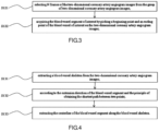
FIG. 3 is a flowchart of S120 of the present disclosure; -
FIG. 4 is a flowchart of S130 of the present disclosure; -
FIG. 5 is a flowchart of an embodiment of S140 of the present disclosure; -
FIG. 6 is a flowchart of another embodiment of S140 of the present disclosure; -
FIG. 7 is a structural block diagram of an embodiment of an apparatus for calculating an adjusted blood flow velocity in maximum hyperemia state based on index for microcirculatory resistance of the present disclosure; -
FIG. 8 is a structural block diagram of another embodiment of an apparatus for calculating an adjusted blood flow velocity in maximum hyperemia state based on index for microcirculatory resistance of the present disclosure; - Reference numerals are explained below:
blood flowvelocity acquisition unit 1, blood flowvelocity calculation module 101, diastolic blood flowvelocity calculation module 102, aortic pressurewaveform acquisition unit 2, physiologicalparameter acquisition unit 3, unit of index for microcirculatory resistance duringdiastolic phase 4, adjustment parameter unit 5,image reading unit 6, blood vesselsegment extraction unit 7,centerline extraction unit 8,time difference unit 9,centerline difference unit 10, blood vessel skeleton extraction unit 11, three-dimensional blood vessel reconstruction unit 12, contour line extraction unit 13, flow velocity correction unit 14, unit of flow velocity inmaximum hyperemia state 15. - In order to make objects, technical solutions and advantages of the present disclosure clearer, the technical solutions of the present disclosure will be clearly and completely described below with reference to the specific embodiments and corresponding drawings. It is apparent that the described embodiments are merely part of the embodiments of the present disclosure rather than all of them. Based on the embodiments in the present disclosure, without making creative work, all the other embodiments obtained by a person skilled in the art will fall into the protection scope of the present disclosure.
- Hereinafter, a number of embodiments of the present disclosure will be disclosed with drawings. For clear illustration, many practical details will be described in the following description. However, it should be understood that the present disclosure should not be limited by these practical details. In other words, in some embodiments of the present disclosure, these practical details are unnecessary. In addition, in order to simplify the drawings, some conventionally used structures and components will be shown in simple schematic ways in the drawings.
- Due to different vital signs of different populations, evaluation standards for normal values are slightly different. For example, the myocardial microcirculation function of the elderly is relatively poor, and the blood flow velocity is generally lower than that of the young. If the industry general evaluation standard is used, the blood flow velocity used will be higher than the actual value. The higher blood flow velocity will further affect the coronary artery evaluation parameters, such as: fractional flow reserve FFR, fractional flow reserve during a diastolic phase iFR, and index for microcirculatory resistance iFMR during the diastolic phase.
- Therefore, at this stage, how to obtain an adjustment parameter according to individual differences, for improving the accuracy of a blood vessel calculation parameter, such as a blood flow velocity, has become an urgent problem in the field of coronary artery technology.
- Embodiment 1: In order to solve the above problem, as shown in
FIG. 1 , the present disclosure provides a method for calculating an adjusted blood flow velocity in maximum hyperemia state based on index for microcirculatory resistance, comprising: - S100, acquiring an index for microcirculatory resistance iFMR during a diastolic phase according to a blood flow velocity v, an aortic pressure waveform, and an physiological parameter;
- S200, making an adjustment parameter r equal to 1 if the index for microcirculatory resistance iFMR during the diastolic phase is less than K; making the adjustment parameter r satisfy a formula

- S300, acquiring a corrected blood flow velocity in a maximum hyperemia state according to a formula v' = rvh ;
- In an embodiment of the present disclosure, vh = z
v +x;
wherein vh represents the blood flow velocity in the maximum hyperemia state,v represents an average blood flow velocity in a heartbeat cycle area, z is a constant in the range of 1 to 3, and x is a constant in the range of 50 to 300; K=50. - According to the present disclosure, an index for microcirculatory resistance iFMR during a diastolic phase is acquired according to a blood flow velocity v, an aortic pressure waveform, and an physiological parameter; then an adjustment parameter is obtained by comparing iFMR with K, where the adjustment parameter varies for different values of iFMR, further, a differentiated parameter is obtained according to individualized differences, placing a solid foundation for the accuracy of a blood vessel calculation parameter, then, a corrected blood flow velocity in the maximum hyperemia state is obtained by a product of the adjustment parameter and the blood flow velocity in the maximum hyperemia state, allowing for more targeted, individualized and more accurate measurement results.
- The present disclosure provides a method for calculating an adjusted blood flow velocity in maximum hyperemia state based on index for microcirculatory resistance, comprising:
S100, acquiring an index for microcirculatory resistance iFMR during a diastolic phase according to a blood flow velocity v, an aortic pressure waveform, and an physiological parameter; wherein - 1) as shown in
FIG. 2 , when acquiring the blood flow velocity through a two-dimensional angiogram image, a manner for acquiring the blood flow velocity v comprises:- S110, reading a group of two-dimensional coronary artery angiogram images of at least one body position;
- S120, extracting a blood vessel segment of interest from the group of two-dimensional coronary artery angiogram images, for which a specific manner is shown in
FIG. 3 , comprising: - S121, selecting N frames of the two-dimensional coronary artery angiogram images from the group of two-dimensional coronary artery angiogram images;
- S122, acquiring the blood vessel segment of interest by picking a beginning point and an ending point of the blood vessel of interest on the two-dimensional coronary artery angiogram images;
- S130, extracting a centerline of the blood vessel segment, for which a specific manner is shown in
FIG. 4 , comprising:- S131, extracting a blood vessel skeleton from the two-dimensional coronary artery angiogram images;
- S132, according to the extension direction of the blood vessel segment and the principle of obtaining the shortest path between two points;
- S133, extracting the centerline of the blood vessel segment along the blood vessel skeleton.
- S140, determining a difference in time taken for a contrast agent flowing through the blood vessel segment in any two frames of the two-dimensional coronary artery angiogram images with the difference being Δt, and determining a difference in centerline length of a sub-segment of the blood vessel segment through which the contrast agent flows in the two frames of two-dimensional coronary artery angiogram image with the difference being ΔL;
- S150, solving the blood flow velocity according to a ratio of ΔL to Δt.
- 2) A manner for acquiring an aortic pressure waveform comprises:
acquiring, in real time, an aortic pressure Paj with an invasive blood pressure sensor or non-invasive blood pressure instrument, where j is a positive integer greater than or equal to 1, and then generating an aortic pressure waveform according to time; - 3) A manner for acquiring the index for microcirculatory resistance iFMR during the diastolic phase comprises:
- S160, selecting a maximum value of the blood flow velocity v obtained by solving in S150, i.e., a maximum blood flow velocity vmax during the diastolic phase;
- S170, a time period corresponding to the vmax being the diastolic phase, acquiring an average aortic pressure during the diastolic phase according to the aortic pressure waveform, namely:

- S180, obtaining a iFMR value according to the calculation formula:

wherein,Pa represents the average aortic pressure during the diastolic phase; P a1, P a2, and Paj represent aortic pressures corresponding to a first point, a second point, and a j-th point within the diastolic phase on the aortic pressure waveform, respectively, and j represents the number of pressure points contained in the aortic pressure waveform during the diastolic phase, vh represents the blood flow velocity in the maximum hyperemia state obtained by selecting a maximum value from all blood flow velocities v, preferably by selecting a maximum value of blood flow velocity through a recursive algorithm or a bubbling algorithm; k and c represent the influence parameters k=1~3, c=0~10; - S200, making an adjustment parameter r equal to 1 if the index for microcirculatory resistance iFMR during the diastolic phase is less than K; making the adjustment parameter r satisfy a formula

wherein K is a positive number less than 100; preferably, K=50.
- All the contents of acquiring coronary artery blood vessel evaluation parameter based on the physiological parameter are within the scope of protection of the present disclosure. After a large number of experimental verifications, histories of having hypertension and diabetes and gender all have impacts on the accuracy of calculating a coronary artery blood vessel evaluation parameter. Therefore, in an embodiment of the present disclosure, an influence parameter k in S180 is calculated by the formula: k=a×b, where a represents a characteristic value of diabetes, b represents a characteristic value of hypertension, and c represents the gender. If a patient does not suffer from diabetes, then 0.5 ≤ a ≤ 1, preferably, a=1; if the patient suffers from diabetes, then 1<a≤2, preferably, a=2; if the patient's blood pressure value is greater than or equal to 90 mmHg, then 1<b≤1.5, preferably, b=1.5; if the patient's blood pressure value is less than 90 mmHg, then 0.5 ≤ b ≤ 1, preferably, b=1; if the patient is male, then c=0; if the patient is female, then c =3~10, preferably, c=5.
- In an embodiment of the present disclosure, S140 comprises two acquisition methods. As shown in
FIG. 5 , method(1) comprises: - S141I, taking the coronary angiogram image when the contrast agent flows to the inlet of the coronary artery, that is, the beginning point of the blood vessel segment as a first frame of image, and taking the coronary angiogram image when the contrast agent flows to the ending point of the blood vessel segment as a N-th frame of image;
- S142I, solving the time difference and centerline length difference of the N-th frame of image and a (N-1)th frame, ..., a (N-b)th frame, ..., a (N-a)th frame, ..., the first frame of image, successively, with the time differences being Δt 1,..., Δtb ,..., Δt a,..., Δt N-1, respectively; the centerline length differences being ΔL 1,..., ΔLb ,..., ΔLa ,..., ΔL N-1, respectively;
- S143I, according to

- In an embodiment of the present disclosure, S140 comprises two acquisition methods. As shown in
FIG. 6 , method(2) comprises: - S141II, taking the coronary angiogram image when the contrast agent flows to the inlet of the coronary artery, that is, the beginning point of the blood vessel segment as a first frame of image, and taking the coronary angiogram image when the contrast agent flows to the ending point of the blood vessel segment as a N-th frame of image;
- S142II, solving the time difference and centerline length difference of the N-th frame and b-th frame, of the (N-1)th frame and (b-1)th frame, ..., of the (N-b-a)th frame and (N-a)th frame, ..., of the (N-b+1)th frame and first frame of image, successively;
- S14311, according to

- In an embodiment of the present disclosure, a manner for acquiring a blood flow velocity by three-dimensional modeling in S100 comprises:
- Step A, reading a group of two-dimensional coronary artery angiogram images of at least two body positions;
- Step B, extracting a blood vessel segment of interest from the groups of two-dimensional coronary artery angiogram images;
- Step C, acquiring geometric structure information of the blood vessel segment and extracting a centerline of the blood vessel segment;
- Step D, performing graphics processing on the blood vessel segment of interest;
- Step E, extracting a blood vessel contour line of the blood vessel segment;
- Step F, according to the geometric structure information of the blood vessel segment, synthesizing a three-dimensional blood vessel model by projecting the at least two body positions' two-dimensional coronary angiogram images which have been extracted centerline and contour line of the blood vessel onto a three-dimensional plane;
- Step G, determining a difference in time taken for a contrast agent flowing through the blood vessel segment in any two frames of the two-dimensional coronary artery angiogram images with the difference being Δt; according to the three-dimensional blood vessel model, acquiring a centerline of the three-dimensional blood vessel model, correcting the centerline extracted from the two-dimensional coronary angiogram images, and determining a difference in the corrected centerline length of a sub-segment of the blood vessel segment through which the contrast agent flows in the two frames of two-dimensional coronary artery angiogram image with the difference being ΔL'; solving the blood flow velocity v according to the ratio of the ΔL' to the Δt.
- Δt =m×fps, since each group of two-dimensional coronary artery angiogram images contains multiple frames of two-dimensional coronary artery angiogram images played consecutively, m represents a difference in frame number between two frames of two-dimensional angiogram image selected from each group of two-dimensional coronary artery angiogram images, and fps represents an interval time for switching between two adjacent frames of the image, preferably, fps=1/15 second.
- The present disclosure provides a method for calculating an adjusted blood flow velocity in maximal hyperemia state based on physiological parameter, comprising:
- the above method for calculating an adjusted blood flow velocity in maximum hyperemia state based on index for microcirculatory resistance;
- according to the formula v' = rvh ;


wherein v' represents a blood flow velocity in the maximum hyperemia state which has been adjusted by a physiological parameter, vh represents a blood flow velocity in the maximum hyperemia state, v represents an average blood flow velocity in a heartbeat cycle area, z is a constant in the range of 1 to 3, and x is a constant in the range of 50 to 300. - An embodiment of the present disclosure provides a method for acquiring coronary artery blood vessel evaluation parameter based on physiological parameter, comprising the above method for acquiring blood flow velocity in maximal hyperemia state based on physiological parameter. A coronary artery blood vessel evaluation parameter comprises: fractional flow reserve FFR, index for microcirculatory resistance IMR, index for microcirculatory resistance iFMR during a diastolic phase, fractional flow reserve iFR during the diastolic phase and the like.
- As shown in
FIG. 7 , the present disclosure provides an apparatus for calculating an adjusted blood flow velocity in maximum hyperemia state based on index for microcirculatory resistance, which is used for the above method for calculating an adjusted blood flow velocity in maximum hyperemia state based on index for microcirculatory resistance, comprising: a blood flowvelocity acquisition unit 1, an aortic pressurewaveform acquisition unit 2, a physiologicalparameter acquisition unit 3, a unit of index for microcirculatory resistance duringdiastolic phase 4 and an adjustment parameter unit 5. The unit of index for microcirculatory resistance duringdiastolic phase 4 is connected with the blood flowvelocity acquisition unit 1, the aortic pressurewaveform acquisition unit 2 and the physiologicalparameter acquisition unit 3. The blood flowvelocity acquisition unit 1 is configured to acquire a blood flow velocity v. The aortic pressurewaveform acquisition unit 2 is configured to acquire, in real time, an aortic pressure waveform changing over time. The physiologicalparameter acquisition unit 3 is configured to acquire physiological parameters of a patient, comprising gender and disease history. The unit of index for microcirculatory resistance duringdiastolic phase 4 is configured to receive the blood flow velocity v, the aortic pressure waveform, and the physiological parameters sent by the blood flowvelocity acquisition unit 1, the aortic pressurewaveform acquisition unit 2, and the physiologicalparameter acquisition unit 3, and then to obtain an index for microcirculatory resistance iFMR during a diastolic phase according to the blood flow velocity v, the aortic pressure waveform, and the physiological parameters. The adjustment parameter unit 5 is configured to receive iFMR value of the unit of index for microcirculatory resistance duringdiastolic phase 4. An adjustment parameter r is equal to 1 if the index for microcirculatory resistance during the diastolic phase iFMR<K; the adjustment parameter r satisfies a formula
- As shown in
FIG. 8 , an embodiment of the present disclosure further comprises: a flow velocity correction unit 14 connected to the adjustment parameter unit 5, a unit of flow velocity inmaximum hyperemia state 15 connected to the flow velocity correction unit 14. The unit of flow velocity inmaximum hyperemia state 15 is configured to calculate a blood flow velocity in a maximum hyperemia state according to vh =zv +x; vh represents the blood flow velocity in the maximum hyperemia state, v represents an average blood flow velocity in a heartbeat cycle area, z is a constant in the range of 1 to 3, and x is a constant in the range of 50 to 300. - As shown in
FIG. 8 , an embodiment of the present application further comprises: animage reading unit 6, a blood vesselsegment extraction unit 7, and acenterline extraction unit 8 connected in sequence, atime difference unit 9 and the physiologicalparameter acquisition unit 3 connected to theimage reading unit 6, and the blood flowvelocity acquisition unit 1 respectively connected with thetime difference unit 9 and acenterline difference unit 10. Thecenterline difference unit 10 is connected with thecenterline extraction unit 8. Theimage reading unit 6 is configured to read a group of two-dimensional coronary artery angiogram image of at least one body position. The blood vesselsegment extraction unit 7 is configured to receive two-dimensional coronary artery angiogram images sent by theimage reading unit 6, and to extract a blood vessel segment of interest in the images. Thecenterline extraction unit 8 is configured to receive the blood vessel segment sent by the blood vesselsegment extraction unit 7, and to extract the centerline of the blood vessel segment. Thetime difference unit 9 is configured to receive any two frames of the two-dimensional coronary artery angiogram images sent by theimage reading unit 6, and to determine a difference in time taken for a contrast agent flowing through the blood vessel segment in the two frames of two-dimensional coronary artery angiogram image with the difference being Δt. Thecenterline difference unit 10 is configured to receive the centerline of a sub-segment of the blood vessel segment flowed through by the contrast agent in the two frames of two-dimensional coronary artery angiogram image sent by the centerline extraction unit, and to determine a difference in centerline length of the sub-segment of the blood vessel segment through which the contrast agent flows in the two frames of two-dimensional coronary artery angiogram image with the difference being ΔL. The blood flowvelocity acquisition unit 1 comprises a blood flowvelocity calculation module 101 and a diastolic blood flowvelocity calculation module 102. The blood flowvelocity calculation module 101 is respectively connected to thetime difference unit 9 and thecenterline difference unit 10. The diastolic blood flowvelocity calculation module 102 is connected with the blood flowvelocity calculation module 101. The blood flowvelocity calculation module 101 is configured to receive the ΔL and the Δt sent by thetime difference unit 9 and thecenterline difference unit 10, and to solve the blood flow velocity according to the ratio of ΔL to Δt. The diastolic blood flowvelocity calculation module 102 is configured to receive the blood flow velocity sent by the blood flowvelocity calculation module 101, and to select a maximum value of the blood flow velocity as a blood flow velocity during a diastolic phase. The physiologicalparameter acquisition unit 3 is configured to receive the two-dimensional coronary artery angiogram images of theimage reading unit 6, to acquire a physiological parameter of a patient, image shooting angles and imaging distance, and to transmit the physiological parameter, image shooting angles and imaging distance to the unit of index for microcirculatory resistance duringdiastolic phase 4. - The above imaging distance may be understood as: when synthesizing a three-dimensional model by two plane images, as long as the distance between the object and the imaging plane, the image shooting angle, and the two two-dimensional plane images are known, the three-dimensional model can be generated through the principle of three-dimensional imaging.
- In an embodiment of the present application, the apparatus further comprises: a blood vessel skeleton extraction unit 11 and a three-dimensional blood vessel reconstruction unit 12, both connected to the
image reading unit 6, a contour line extraction unit 13 connected to the blood vessel skeleton extraction unit 11. The three-dimensional blood vessel reconstruction unit 12 is connected with the physiologicalparameter acquisition unit 3, thecenterline extraction unit 8 and the contour line extraction unit 13. The blood vessel skeleton extraction unit 11 is configured to receive the two-dimensional coronary artery angiogram images sent by theimage reading unit 6, and to extract a blood vessel skeleton in the images. The contour line extraction unit 13 is configured to receive the blood vessel skeleton of the blood vessel skeleton extraction unit 11, and to extract a contour line of the blood vessel segment of interest according to the blood vessel skeleton. The three-dimensional blood vessel reconstruction unit 12 is configured to receive the contour line, the image shooting angles and the centerline sent by the contour line extraction unit 13, the physiologicalparameter acquisition unit 3 and thecenterline extraction unit 8, and to receive the two-dimensional coronary artery angiogram images sent by theimage reading unit 6 in order to synthesize a three-dimensional blood vessel model by projecting at least two body positions' two-dimensional coronary angiogram images which have been extracted centerline and contour line of the blood vessel onto a three-dimensional plane according to the geometric structure information of the blood vessel segment. Thecenterline extraction unit 8 is configured to re-extract the centerline of the blood vessel segment from the three-dimensional blood vessel model of the three-dimensional blood vessel reconstruction unit 12, and to re-acquire the length of the centerline. - The present disclosure provides a coronary artery analysis system, which comprises the apparatus for calculating an adjusted blood flow velocity in maximum hyperemia state based on index for microcirculatory resistance according to any one of the above.
- The present disclosure provides a computer storage medium having stored thereon a computer program to be executed by a processor, wherein the above method for calculating an adjusted blood flow velocity in maximum hyperemia state based on index for microcirculatory resistance is implemented when the computer program is executed by the processor.
- A person skilled in the art knows that various aspects of the present disclosure can be implemented as a system, a method, or a computer program product. Therefore, each aspect of the present disclosure can be specifically implemented in the following forms, namely: complete hardware implementation, complete software implementation (including firmware, resident software, microcode, etc.), or a combination of hardware and software implementations, which here can be collectively referred to as "circuit", "module" or "system". In addition, in some embodiments, various aspects of the present disclosure may also be implemented in the form of a computer program product in one or more computer-readable media, and the computer-readable medium contains computer-readable program code. Implementation of a method and/or a system of embodiments of the present disclosure may involve performing or completing selected tasks manually, automatically, or a combination thereof.
- For example, hardware for performing selected tasks according to the embodiment(s) of the present disclosure may be implemented as a chip or a circuit. As software, selected tasks according to the embodiment(s) of the present disclosure can be implemented as a plurality of software instructions executed by a computer using any suitable operating system. In the exemplary embodiment(s) of the present disclosure, a data processor performs one or more tasks according to the exemplary embodiment(s) of a method and/or system as described herein, such as a computing platform for executing multiple instructions. Optionally, the data processor comprises a volatile memory for storing instructions and/or data, and/or a non-volatile memory for storing instructions and/or data, for example, a magnetic hard disk and/or movable medium. Optionally, a network connection is also provided. Optionally, a display and/or user input device, such as a keyboard or mouse, are/is also provided.
- Any combination of one or more computer readable media can be utilized. The computer-readable medium may be a computer-readable signal medium or a computer-readable storage medium. The computer-readable storage medium may be, for example, but not limited to, an electrical, magnetic, optical, electromagnetic, infrared, or semiconductor system, apparatus, or device, or any combination of the above. More specific examples (non-exhaustive list) of computer-readable storage media would include the following:
Electrical connection with one or more wires, portable computer disk, hard disk, random access memory (RAM), read only memory (ROM), erasable programmable read only memory (EPROM or flash memory), optical fiber, portable compact disk read only memory (CD-ROM), optical storage device, magnetic storage device, or any suitable combination of the above. In this document, the computer-readable storage medium can be any tangible medium that contains or stores a program, and the program can be used by or in combination with an instruction execution system, apparatus, or device. - The computer-readable signal medium may include a data signal propagated in baseband or as a part of a carrier wave, which carries computer-readable program code. This data signal for propagation can take many forms, including but not limited to electromagnetic signals, optical signals, or any suitable combination of the above. The computer-readable signal medium may also be any computer-readable medium other than the computer-readable storage medium. The computer-readable medium can send, propagate, or transmit a program for use by or in combination with the instruction execution system, apparatus, or device.
- The program code contained in the computer-readable medium can be transmitted by any suitable medium, including, but not limited to, wireless, wired, optical cable, RF, etc., or any suitable combination of the above.
- For example, any combination of one or more programming languages can be used to write computer program codes for performing operations for various aspects of the present disclosure, including object-oriented programming languages such as Java, Smalltalk, C++, and conventional process programming languages, such as "C" programming language or similar programming language. The program code can be executed entirely on a user's computer, partly on a user's computer, executed as an independent software package, partly on a user's computer and partly on a remote computer, or entirely on a remote computer or server. In the case of a remote computer, the remote computer can be connected to a user's computer through any kind of network including a local area network (LAN) or a wide area network (WAN), or it can be connected to an external computer (for example, connected through Internet provided by an Internet service provider).
- It should be understood that each block of the flowcharts and/or block diagrams and combinations of blocks in the flowcharts and/or block diagrams can be implemented by computer program instructions. These computer program instructions can be provided to the processor of general-purpose computers, special-purpose computers, or other programmable data processing devices to produce a machine, which produces a device that implements the functions/actions specified in one or more blocks in the flowcharts and/or block diagrams when these computer program instructions are executed by the processor of the computer or other programmable data processing devices.
- It is also possible to store these computer program instructions in a computer-readable medium. These instructions make computers, other programmable data processing devices, or other devices work in a specific manner, so that the instructions stored in the computer-readable medium generate an article of manufacture comprising instructions for implementation of the functions/actions specified in one or more blocks in the flowcharts and/or block diagrams.
- Computer program instructions can also be loaded onto a computer (for example, a coronary artery analysis system) or other programmable data processing equipment to facilitate a series of operation steps to be performed on the computer, other programmable data processing apparatus or other apparatus to produce a computer-implemented process, which enable instructions executed on a computer, other programmable device, or other apparatus to provide a process for implementing the functions/actions specified in the flowcharts and/or one or more block diagrams.
- The above specific examples of the present disclosure further describe the purpose, technical solutions and beneficial effects of the present disclosure in detail. It should be understood that the above are only specific embodiments of the present disclosure and are not intended to limit the present disclosure. The invention is defined by the appended claims.
Claims (19)
- A computer-implemented method for calculating an adjusted blood flow velocity in maximum hyperemia state based on index for microcirculatory resistance, characterized by comprising:acquiring an index for microcirculatory resistance iFMR during a diastolic phase according to a blood flow velocity v, an aortic pressure waveform, and an physiological parameter;making an adjustment parameter r equal to 1 if the index for microcirculatory resistance iFMR during the diastolic phase is less than K; making the adjustment parameter r satisfy a formula
 acquiring a corrected blood flow velocity in a maximum hyperemia state according to a formula v' = rvh ;wherein v' represents the corrected blood flow velocity in the maximum hyperemia state, and vh represents a blood flow velocity in the maximum hyperemia state.
 - The method for calculating an adjusted blood flow velocity in maximum hyperemia state based on index for microcirculatory resistance according to claim 1, characterized in that,

v represents an average blood flow velocity in a heartbeat cycle area, z is a constant in the range of 1 to 3, and x is a constant in the range of 50 to 300; K=50. - The method for calculating an adjusted blood flow velocity in maximum hyperemia state based on index for microcirculatory resistance according to claim 1, characterized in that, a manner for acquiring an index for microcirculatory resistance iFMR during a diastolic phase according to a blood flow velocity v, an aortic pressure waveform, and an physiological parameter comprises:selecting a maximum value of the blood flow velocity v, i.e., a maximum blood flow velocity vmax during the diastolic phase;a time period corresponding to the vmax being the diastolic phase, acquiring an average aortic pressure during the diastolic phase according to the aortic pressure waveform;

 wherein,
Pa represents the average aortic pressure during the diastolic phase; P a1, P a2, and Paj represent aortic pressures corresponding to a first point, a second point, and a j-th point within the diastolic phase on the aortic pressure waveform, respectively, and j represents the number of pressure points contained in the aortic pressure waveform during the diastolic phase, vh represents the blood flow velocity in the maximum hyperemia state obtained by selecting a maximum value from all blood flow velocities v; k and c represent the influence parameters k=1~3, c=0~10, - The method for calculating an adjusted blood flow velocity in maximum hyperemia state based on index for microcirculatory resistance according to claim 3, characterized in that, the influence parameter k=a×b, wherein a represents a characteristic value of diabetes, b represents a characteristic value of hypertension, and c represents gender.
- The method for calculating an adjusted blood flow velocity in maximum hyperemia state based on index for microcirculatory resistance according to claim 4, characterized in that, if a patient does not suffer from diabetes, then 0.5 ≤ a ≤ 1;if the patient suffers from diabetes, then 1 < a≤2;if the patient's blood pressure is greater than or equal to 90 mmHg, then 1<b≤1.5; if the patient's blood pressure is less than 90 mmHg, then 0.5≤b≤1;if the patient is male, then c=0; if the patient is female, then c=3~10.
- The method for calculating an adjusted blood flow velocity in maximum hyperemia state based on index for microcirculatory resistance according to claim 5, characterized in that, if the patient does not suffer from diabetes, then a=1; If the patient suffers from diabetes, then a=2;if the patient's blood pressure is greater than or equal to 90 mmHg, then b=1.5; if the patient's blood pressure is less than 90 mmHg, then b=1;if the patient is male, c=0; if the patient is female, c=5.
- The method for calculating an adjusted blood flow velocity in maximum hyperemia state based on index for microcirculatory resistance according to claim 1, characterized in that, a manner for acquiring a blood flow velocity comprises:reading a group of two-dimensional coronary artery angiogram images of at least one body position;extracting a blood vessel segment of interest from the group of two-dimensional coronary artery angiogram images;extracting a centerline of the blood vessel segment;determining a difference in time taken for a contrast agent flowing through the blood vessel segment in any two frames of the two-dimensional coronary artery angiogram images with the difference being Δt, and determining a difference in centerline length of a sub-segment of the blood vessel segment through which the contrast agent flows in the two frames of two-dimensional coronary artery angiogram image with the difference being ΔL ;solving the blood flow velocity according to a ratio of ΔL to Δt.
- The method for calculating an adjusted blood flow velocity in maximum hyperemia state based on index for microcirculatory resistance according to claim 7, characterized in that, a manner for extracting a blood vessel segment of interest from the group of two-dimensional coronary artery angiogram images comprises:selecting N frames of the two-dimensional coronary artery angiogram images from the group of two-dimensional coronary artery angiogram images;acquiring the blood vessel segment of interest by picking a beginning point and an ending point of the blood vessel of interest on the two-dimensional coronary artery angiogram images.
- The method for calculating an adjusted blood flow velocity in maximum hyperemia state based on index for microcirculatory resistance according to claim 7, characterized in that, a manner for extracting the centerline of the blood vessel segment comprises:extracting a blood vessel skeleton from the two-dimensional coronary artery angiogram images;according to an extension direction of the blood vessel segment and a principle of obtaining the shortest path between two points;extracting the centerline of the blood vessel segment along the blood vessel skeleton.
- The method for calculating an adjusted blood flow velocity in maximum hyperemia state based on index for microcirculatory resistance according to claim 7, characterized in that, a manner for determining a difference in time taken for a contrast agent flowing through the blood vessel segment in any two frames of the two-dimensional coronary artery angiogram images with the difference being Δt, and determining a difference in centerline length of a sub-segment of the blood vessel segment through which the contrast agent flows in the two frames of two-dimensional coronary artery angiogram image with the difference being ΔL , and solving the blood flow velocity according to the ratio of ΔL to Δt comprises:taking the coronary angiogram image when the contrast agent flows to the inlet of the coronary artery, that is, the beginning point of the blood vessel segment as a first frame of image, and taking the coronary angiogram image when the contrast agent flows to the ending point of the blood vessel segment as a N-th frame of image;solving the time difference and centerline length difference of the N-th frame of image and a (N-1)th frame, ..., a (N-b)th frame, ..., a (N-a)th frame, ..., the first frame of image, successively, with the time differences being Δt 1,..., Δt b,..., Δt a,..., Δt N-1, respectively; the centerline length differences being ΔL 1,..., ΔLb ,..., ΔLa ,..., ΔL N-1, respectively;according to

- The method for calculating an adjusted blood flow velocity in maximum hyperemia state based on index for microcirculatory resistance according to claim 7, characterized in that, a manner for determining a difference in time taken a contrast agent flowing through the blood vessel segment in any two frames of the two-dimensional coronary artery angiogram images with the difference being Δt, and determining a difference in centerline length of a sub-segment of the blood vessel segment through which the contrast agent flows in the two frames of two-dimensional coronary artery angiogram image with the difference being ΔL , and solving the blood flow velocity according to the ratio of ΔL to Δt comprises:solving the time difference and centerline length difference of the N-th frame and b-th frame, of the (N-1)th frame and (b-1)th frame, ..., of the (N-b-a)th frame and (N-a)th frame, ..., of the (N-b+1)th frame and first frame of image, successively;according to

- The method for calculating an adjusted blood flow velocity in maximum hyperemia state based on index for microcirculatory resistance according to claim 7, characterized in that, after the manner for extracting a centerline of the blood vessel segment, and before the manner for determining a difference in time taken for a contrast agent flowing through the blood vessel segment in any two frames of the two-dimensional coronary artery angiogram images with the difference being Δt, and determining a difference in centerline length of a sub-segment of the blood vessel segment through which the contrast agent flows in the two frames of two-dimensional coronary artery angiogram image with the difference being ΔL , further comprises:reading a group of two-dimensional coronary artery angiogram images of at least two body positions;acquiring geometric structure information of the blood vessel segment;performing graphics processing on the blood vessel segment of interest;extracting a blood vessel contour line of the blood vessel segment;according to the geometric structure information of the blood vessel segment, synthesizing a three-dimensional blood vessel model by projecting the at least two body positions' two-dimensional coronary angiogram images which have been extracted centerline and contour line of the blood vessel onto a three-dimensional plane.
- The method for calculating an adjusted blood flow velocity in maximum hyperemia state based on index for microcirculatory resistance according to claim 12, characterized in that, a manner for solving the blood flow velocity according to the ratio of ΔL to Δt comprises:according to the three-dimensional blood vessel model, acquiring a centerline of the three-dimensional blood vessel model, correcting the centerline extracted from the two-dimensional coronary angiogram images, and correcting the centerline difference ΔL to obtain ΔL';solving the blood flow velocity v according to the ratio of the ΔL' to the Δt.
- A method for acquiring coronary artery blood vessel evaluation parameter based on physiological parameter, characterized by comprising: the method for calculating an adjusted blood flow velocity in maximum hyperemia state based on index for microcirculatory resistance according to claim 13 .
- An apparatus for calculating an adjusted blood flow velocity in maximum hyperemia state based on index for microcirculatory resistance, configured to carry out the method for calculating an adjusted blood flow velocity in maximum hyperemia state based on index for microcirculatory resistance according to any one of the claims 1 to 13, characterized by comprising: a blood flow velocity acquisition unit (1), an aortic pressure waveform acquisition unit (2), a physiological parameter acquisition unit (3), a unit of index for microcirculatory resistance during diastolic phase (4) and an adjustment parameter unit (5); the unit of index for microcirculatory resistance during diastolic phase (4) being connected with the blood flow velocity acquisition unit (1), the aortic pressure waveform acquisition unit (2) and the physiological parameter acquisition unit (3);the blood flow velocity acquisition unit (1) being configured to acquire a blood flow velocity v;the aortic pressure waveform acquisition unit (2) being configured to acquire, in real time, an aortic pressure waveform changing over time;the physiological parameter acquisition unit (3) being configured to acquire physiological parameters of a patient, comprising gender and disease history;the unit of index for microcirculatory resistance during diastolic phase (4) being configured to receive the blood flow velocity v, the aortic pressure waveform, and the physiological parameters sent by the blood flow velocity acquisition unit (1), the aortic pressure waveform acquisition unit (2), and the physiological parameter acquisition unit (3), and then to obtain an index for microcirculatory resistance iFMR during a diastolic phase according to the blood flow velocity v, the aortic pressure waveform, and the physiological parameters;the adjustment parameter unit (5) being configured to receive iFMR value of the unit of index for microcirculatory resistance during diastolic phase (4); make an adjustment parameter r equal to 1 if the index for microcirculatory resistance during the diastolic phase iFMR<K; make the adjustment parameter r satisfy a formula

- The apparatus for calculating an adjusted blood flow velocity in maximum hyperemia state based on index for microcirculatory resistance according to claim 15, characterized by further comprising: an image reading unit (6), a blood vessel segment extraction unit (7), and a centerline extraction unit (8) connected in sequence, a time difference unit (9) and the physiological parameter acquisition unit (3) connected to the image reading unit (6), the blood flow velocity acquisition unit (1) being connected with the time difference unit (9) and a centerline difference unit (10), respectively; the centerline difference unit (10) being connected with the centerline extraction unit (8);the image reading unit (6) being configured to read a group of two-dimensional coronary artery angiogram image of at least one body position;the blood vessel segment extraction unit (7) being configured to receive two-dimensional coronary artery angiogram images sent by the image reading unit (6), and to extract a blood vessel segment of interest in the images;the centerline extraction unit (8) being configured to receive the blood vessel segment sent by the blood vessel segment extraction unit (7), and to extract the centerline of the blood vessel segment;the time difference unit (9) being configured to receive any two frames of the two-dimensional coronary artery angiogram images sent by the image reading unit (6), and to determine a difference in time taken for a contrast agent flowing through the blood vessel segment in the two frames of two-dimensional coronary artery angiogram image with the difference being Δt;the centerline difference unit (10) being configured to receive the centerline of a sub-segment of the blood vessel segment flowed through by the contrast agent in the two frames of two-dimensional coronary artery angiogram image sent by the centerline extraction unit, and to determine a difference in centerline length of the sub-segment of the blood vessel segment through which the contrast agent flows in the two frames of two-dimensional coronary artery angiogram image with the difference being ΔL;the blood flow velocity acquisition unit (1), comprising a blood flow velocity calculation module (101) and a diastolic blood flow velocity calculation module (102), the blood flow velocity calculation module (101) being respectively connected to the time difference unit (9) and the centerline difference unit (10), the diastolic blood flow velocity calculation module (102) being connected with the blood flow velocity calculation module (101);the blood flow velocity calculation module (101) being configured to receive the ΔL and the Δt sent by the time difference unit (9) and the centerline difference unit (10), and to solve the blood flow velocity according to the ratio of ΔL to Δt;the diastolic blood flow velocity calculation module (102) being configured to receive the blood flow velocity sent by the blood flow velocity calculation module (101), and to select a maximum value of the blood flow velocity as a blood flow velocity during a diastolic phase;the physiological parameter acquisition unit (3) being configured to receive the two-dimensional coronary artery angiogram images of the image reading unit (6), to acquire a physiological parameter of a patient and image shooting angles, and to transmit the physiological parameter and image shooting angles to the unit of index for microcirculatory resistance during diastolic phase (4).
- The apparatus for calculating an adjusted blood flow velocity in maximum hyperemia state based on index of microcirculatory resistance according to claim 16, further comprising: a blood vessel skeleton extraction unit (11) and a three-dimensional blood vessel reconstruction unit (12), both connected to the image reading unit (6), a contour line extraction unit (13) connected to the blood vessel skeleton extraction unit (11), the three-dimensional blood vessel reconstruction unit (12) being connected with the physiological parameter acquisition unit (3), the centerline extraction unit (8) and the contour line extraction unit (13);the blood vessel skeleton extraction unit (11) being configured to receive the two-dimensional coronary artery angiogram images sent by the image reading unit (6), and to extract a blood vessel skeleton in the images;the contour line extraction unit (13) being configured to receive the blood vessel skeleton of the blood vessel skeleton extraction unit (11), and to extract a contour line of the blood vessel segment of interest according to the blood vessel skeleton;the three-dimensional blood vessel reconstruction unit (12) being configured to receive the contour line, the image shooting angles and the centerline sent by the contour line extraction unit (13), the physiological parameter acquisition unit (3) and the centerline extraction unit (8), and to receive the two-dimensional coronary artery angiogram images sent by the image reading unit (6) in order to synthesize a three-dimensional blood vessel model by projecting the two-dimensional coronary angiogram images of at least two body positions with extracted centerline and contour line of the blood vessel onto a three-dimensional plane and according to the geometric structure information of the blood vessel segment;the centerline extraction unit (8) being configured to re-extract the centerline of the blood vessel segment from the three-dimensional blood vessel model of the three-dimensional blood vessel reconstruction unit (12), and to re-acquire the length of the centerline.
- A coronary artery analysis system, characterized by comprising: the apparatus for calculating an adjusted blood flow velocity in maximum hyperemia state based on index for microcirculatory resistance according to any one of claims 15 to 17.
- A computer storage medium having stored thereon a computer program to be executed by a processor, characterized in that, the method for calculating an adjusted blood flow velocity in maximum hyperemia state based on index for microcirculatory resistance according to any one of claims 1 to 13 is implemented when the computer program is executed by the processor.
Applications Claiming Priority (2)
| Application Number | Priority Date | Filing Date | Title |
|---|---|---|---|
| CN201911065694.6A CN110786841B (en) | 2019-11-04 | 2019-11-04 | Method and device for adjusting maximum hyperemia state flow rate based on microcirculation resistance index |
| PCT/CN2019/116674 WO2021087968A1 (en) | 2019-11-04 | 2019-11-08 | Method and apparatus for adjusting blood flow velocity in largest congestion state on basis of microcirculation resistance index |
Publications (4)
| Publication Number | Publication Date |
|---|---|
| EP4056110A1 EP4056110A1 (en) | 2022-09-14 |
| EP4056110A4 EP4056110A4 (en) | 2023-12-06 |
| EP4056110B1 true EP4056110B1 (en) | 2024-10-09 |
| EP4056110C0 EP4056110C0 (en) | 2024-10-09 |
Family
ID=69442547
Family Applications (1)
| Application Number | Title | Priority Date | Filing Date |
|---|---|---|---|
| EP19952100.6A Active EP4056110B1 (en) | 2019-11-04 | 2019-11-08 | Method and apparatus for calculating an adjusted blood flow velocity in largest congestion state on basis of microcirculation resistance index |
Country Status (5)
| Country | Link |
|---|---|
| US (1) | US20220254028A1 (en) |
| EP (1) | EP4056110B1 (en) |
| JP (1) | JP7385318B2 (en) |
| CN (1) | CN110786841B (en) |
| WO (1) | WO2021087968A1 (en) |
Families Citing this family (15)
| Publication number | Priority date | Publication date | Assignee | Title |
|---|---|---|---|---|
| US10210956B2 (en) | 2012-10-24 | 2019-02-19 | Cathworks Ltd. | Diagnostically useful results in real time |
| EP4300419A3 (en) | 2016-05-16 | 2024-04-03 | Cathworks Ltd. | System for vascular assessment |
| CN111227821B (en) * | 2018-11-28 | 2022-02-11 | 苏州润迈德医疗科技有限公司 | Microcirculation resistance index calculation method based on myocardial blood flow and CT (computed tomography) images |
| IL286814B2 (en) | 2019-04-01 | 2026-03-01 | Cathworks Ltd | Methods and apparatus for angiographic image selection |
| EP4555935A3 (en) | 2019-09-23 | 2025-07-30 | Cathworks Ltd. | Methods, apparatus, and system for synchronization between a three-dimensional vascular model and an imaging device |
| CN112164020B (en) * | 2020-03-31 | 2024-01-23 | 苏州润迈德医疗科技有限公司 | Method, device, analysis system and storage medium for accurately extracting blood vessel center line |
| CN112690814B (en) * | 2020-11-06 | 2022-10-14 | 杭州阿特瑞科技有限公司 | Low-error coronary artery blood flow reserve fraction measuring method |
| CN112971818B (en) * | 2021-01-28 | 2022-10-04 | 杭州脉流科技有限公司 | Method and device for acquiring microcirculation resistance index, computer equipment and storage medium |
| US12315076B1 (en) | 2021-09-22 | 2025-05-27 | Cathworks Ltd. | Four-dimensional motion analysis of a patient's coronary arteries and myocardial wall |
| EP4645221A3 (en) | 2022-02-10 | 2025-12-31 | Cathworks Ltd. | SYSTEM AND METHOD FOR MACHINE LEARNING-BASED SENSOR ANALYSIS AND VASCULAR TREE SEGMENTATION |
| CN116206162B (en) * | 2023-04-28 | 2023-08-01 | 杭州脉流科技有限公司 | Coronary blood flow reserve acquisition method, device and equipment based on contrast images |
| KR20260052078A (en) | 2023-08-09 | 2026-04-17 | 캐스웍스 엘티디. | Enhanced user interface and crosstalk analysis for vascular index measurement |
| KR20260048313A (en) | 2023-08-09 | 2026-04-09 | 캐스웍스 엘티디. | Coronary artery analysis after PCI |
| CN118013233B (en) * | 2024-04-07 | 2024-08-02 | 中汽研汽车检验中心(天津)有限公司 | Construction method for predictive cruising test working condition of heavy commercial vehicle |
| US12567489B2 (en) | 2024-06-12 | 2026-03-03 | Cathworks Ltd. | Systems and methods for displaying distal fractional flow reserve values in vascular analysis |
Family Cites Families (15)
| Publication number | Priority date | Publication date | Assignee | Title |
|---|---|---|---|---|
| CN1559345A (en) * | 2004-02-20 | 2005-01-05 | 无锡贝尔森影像技术有限公司 | Method and apparatus for detecting blood dynamics of brain blood vessel |
| WO2017187269A1 (en) | 2016-04-29 | 2017-11-02 | Siemens Healthcare Gmbh | Enhanced personalized evaluation of coronary artery disease using an integration of multiple medical imaging techniques |
| JP7010932B2 (en) | 2016-09-20 | 2022-01-26 | ハートフロー, インコーポレイテッド | Systems and methods for monitoring and updating blood flow calculations using user-specific anatomical and physiological sensor data |
| CN107689032A (en) * | 2017-07-05 | 2018-02-13 | 北京工业大学 | A kind of noninvasive method for calculating coronary branches CBF under patient's maximum congestive state of personalization |
| CN107730540B (en) | 2017-10-09 | 2020-11-17 | 全景恒升(北京)科学技术有限公司 | Coronary parameter calculation method based on high-precision matching model |
| CN110853029B (en) * | 2017-11-15 | 2021-04-30 | 深圳科亚医疗科技有限公司 | Methods, systems and media for automatic prediction of blood flow characteristics based on medical images |
| CN107978371B (en) * | 2017-11-30 | 2021-04-02 | 博动医学影像科技(上海)有限公司 | Method and system for rapidly calculating micro-circulation resistance |
| CN108550189A (en) * | 2018-05-03 | 2018-09-18 | 苏州润迈德医疗科技有限公司 | Microcirculation drag index computational methods based on contrastographic picture and fluid mechanic model |
| CN109009037B (en) * | 2018-06-20 | 2021-11-19 | 博动医学影像科技(上海)有限公司 | Calculation method and device for acquiring vascular pressure difference based on individual sex |
| CN108742570B (en) | 2018-06-20 | 2021-10-01 | 博动医学影像科技(上海)有限公司 | Device for acquiring blood vessel pressure difference based on coronary artery advantage type |
| CN108742587B (en) * | 2018-06-20 | 2021-04-27 | 博动医学影像科技(上海)有限公司 | Method and device for acquiring blood flow characteristic value based on medical history information |
| CN110367965B (en) * | 2018-09-19 | 2022-03-08 | 苏州润迈德医疗科技有限公司 | Method, device and system for conveniently measuring coronary artery blood vessel evaluation parameters |
| CN110384493A (en) * | 2018-09-19 | 2019-10-29 | 苏州润迈德医疗科技有限公司 | Measure the system and coronary artery analysis system of microcirculation drag index |
| CN110384494A (en) * | 2018-09-19 | 2019-10-29 | 苏州润迈德医疗科技有限公司 | The method for measuring microcirculation drag index |
| CN109770930B (en) * | 2019-01-29 | 2021-03-09 | 浙江大学 | A method and device for determining coronary microcirculation resistance |
-
2019
- 2019-11-04 CN CN201911065694.6A patent/CN110786841B/en active Active
- 2019-11-08 EP EP19952100.6A patent/EP4056110B1/en active Active
- 2019-11-08 JP JP2022525374A patent/JP7385318B2/en active Active
- 2019-11-08 WO PCT/CN2019/116674 patent/WO2021087968A1/en not_active Ceased
-
2022
- 2022-04-28 US US17/731,607 patent/US20220254028A1/en not_active Abandoned
Also Published As
| Publication number | Publication date |
|---|---|
| WO2021087968A1 (en) | 2021-05-14 |
| CN110786841A (en) | 2020-02-14 |
| JP2022554298A (en) | 2022-12-28 |
| JP7385318B2 (en) | 2023-11-22 |
| EP4056110A1 (en) | 2022-09-14 |
| US20220254028A1 (en) | 2022-08-11 |
| CN110786841B (en) | 2021-05-25 |
| EP4056110C0 (en) | 2024-10-09 |
| EP4056110A4 (en) | 2023-12-06 |
Similar Documents
| Publication | Publication Date | Title |
|---|---|---|
| US20220254028A1 (en) | Method and apparatus for adjusting blood flow velocity in maximum hyperemia state based on index for microcirculatory resistance | |
| US20220261997A1 (en) | Method and apparatus for acquiring blood vessel evaluation parameter based on physiological parameter, and storage medium | |
| EP3881758B1 (en) | Method, apparatus and system for acquiring vascular assessment parameter on basis of angiographic image | |
| US20220277447A1 (en) | Method and apparatus for acquiring contour line of blood vessel according to centerline of blood vessel | |
| EP4131150A1 (en) | Method and apparatus for accurately extracting vessel centerline, analysis system, and storage medium | |
| CN110889896B (en) | Method, device and system for acquiring vascular stenosis interval and three-dimensional synthesis | |
| US10580526B2 (en) | System and method for calculating vessel flow parameters based on angiography | |
| CN105380630B (en) | heart rate path optimizer | |
| CN108665449B (en) | Deep learning model and device for predicting blood flow characteristics on blood flow vector path | |
| CN112132949B (en) | Three-dimensional modeling method, device and system for blood vessel with narrow lesion region | |
| CN103327904B (en) | Ultrasound image capture device, ultrasound image capture method | |
| JP2022554298A5 (en) | ||
| CN110786842B (en) | Method, device, system and storage medium for measuring diastolic blood flow velocity | |
| CN110432886A (en) | Method, device and system for obtaining average blood flow and flow velocity at coronary outlet | |
| WO2021031355A1 (en) | Method and apparatus for measuring pressure and ratio in wave-free period, and system and storage medium | |
| CN110929604B (en) | Method, device, system and storage medium for screening flow velocity based on contrast image | |
| US20240242839A1 (en) | Left ventricular hypertrophy prediction model training method and device thereof |
Legal Events
| Date | Code | Title | Description |
|---|---|---|---|
| STAA | Information on the status of an ep patent application or granted ep patent |
Free format text: STATUS: THE INTERNATIONAL PUBLICATION HAS BEEN MADE |
|
| PUAI | Public reference made under article 153(3) epc to a published international application that has entered the european phase |
Free format text: ORIGINAL CODE: 0009012 |
|
| STAA | Information on the status of an ep patent application or granted ep patent |
Free format text: STATUS: REQUEST FOR EXAMINATION WAS MADE |
|
| 17P | Request for examination filed |
Effective date: 20220429 |
|
| AK | Designated contracting states |
Kind code of ref document: A1 Designated state(s): AL AT BE BG CH CY CZ DE DK EE ES FI FR GB GR HR HU IE IS IT LI LT LU LV MC MK MT NL NO PL PT RO RS SE SI SK SM TR |
|
| DAV | Request for validation of the european patent (deleted) | ||
| DAX | Request for extension of the european patent (deleted) | ||
| REG | Reference to a national code |
Ref country code: DE Ref legal event code: R079 Free format text: PREVIOUS MAIN CLASS: A61B0005027500 Ipc: A61B0005000000 Ref country code: DE Ref legal event code: R079 Ref document number: 602019060364 Country of ref document: DE Free format text: PREVIOUS MAIN CLASS: A61B0005027500 Ipc: A61B0005000000 |
|
| A4 | Supplementary search report drawn up and despatched |
Effective date: 20231107 |
|
| RIC1 | Information provided on ipc code assigned before grant |
Ipc: G06T 7/11 20170101ALI20231031BHEP Ipc: G06T 7/00 20170101ALI20231031BHEP Ipc: A61B 34/10 20160101ALI20231031BHEP Ipc: A61B 5/107 20060101ALI20231031BHEP Ipc: A61B 5/0275 20060101ALI20231031BHEP Ipc: A61B 5/02 20060101ALI20231031BHEP Ipc: A61B 5/00 20060101AFI20231031BHEP |
|
| GRAP | Despatch of communication of intention to grant a patent |
Free format text: ORIGINAL CODE: EPIDOSNIGR1 |
|
| STAA | Information on the status of an ep patent application or granted ep patent |
Free format text: STATUS: GRANT OF PATENT IS INTENDED |
|
| INTG | Intention to grant announced |
Effective date: 20240510 |
|
| GRAS | Grant fee paid |
Free format text: ORIGINAL CODE: EPIDOSNIGR3 |
|
| GRAA | (expected) grant |
Free format text: ORIGINAL CODE: 0009210 |
|
| STAA | Information on the status of an ep patent application or granted ep patent |
Free format text: STATUS: THE PATENT HAS BEEN GRANTED |
|
| AK | Designated contracting states |
Kind code of ref document: B1 Designated state(s): AL AT BE BG CH CY CZ DE DK EE ES FI FR GB GR HR HU IE IS IT LI LT LU LV MC MK MT NL NO PL PT RO RS SE SI SK SM TR |
|
| REG | Reference to a national code |
Ref country code: CH Ref legal event code: EP |
|
| REG | Reference to a national code |
Ref country code: DE Ref legal event code: R096 Ref document number: 602019060364 Country of ref document: DE |
|
| REG | Reference to a national code |
Ref country code: IE Ref legal event code: FG4D |
|
| U01 | Request for unitary effect filed |
Effective date: 20241018 |
|
| U07 | Unitary effect registered |
Designated state(s): AT BE BG DE DK EE FI FR IT LT LU LV MT NL PT RO SE SI Effective date: 20241104 |
|
| U20 | Renewal fee for the european patent with unitary effect paid |
Year of fee payment: 6 Effective date: 20241122 |
|
| PG25 | Lapsed in a contracting state [announced via postgrant information from national office to epo] |
Ref country code: IS Free format text: LAPSE BECAUSE OF FAILURE TO SUBMIT A TRANSLATION OF THE DESCRIPTION OR TO PAY THE FEE WITHIN THE PRESCRIBED TIME-LIMIT Effective date: 20250209 Ref country code: HR Free format text: LAPSE BECAUSE OF FAILURE TO SUBMIT A TRANSLATION OF THE DESCRIPTION OR TO PAY THE FEE WITHIN THE PRESCRIBED TIME-LIMIT Effective date: 20241009 |
|
| PG25 | Lapsed in a contracting state [announced via postgrant information from national office to epo] |
Ref country code: ES Free format text: LAPSE BECAUSE OF FAILURE TO SUBMIT A TRANSLATION OF THE DESCRIPTION OR TO PAY THE FEE WITHIN THE PRESCRIBED TIME-LIMIT Effective date: 20241009 |
|
| PG25 | Lapsed in a contracting state [announced via postgrant information from national office to epo] |
Ref country code: NO Free format text: LAPSE BECAUSE OF FAILURE TO SUBMIT A TRANSLATION OF THE DESCRIPTION OR TO PAY THE FEE WITHIN THE PRESCRIBED TIME-LIMIT Effective date: 20250109 |
|
| PG25 | Lapsed in a contracting state [announced via postgrant information from national office to epo] |
Ref country code: GR Free format text: LAPSE BECAUSE OF FAILURE TO SUBMIT A TRANSLATION OF THE DESCRIPTION OR TO PAY THE FEE WITHIN THE PRESCRIBED TIME-LIMIT Effective date: 20250110 |
|
| PG25 | Lapsed in a contracting state [announced via postgrant information from national office to epo] |
Ref country code: PL Free format text: LAPSE BECAUSE OF FAILURE TO SUBMIT A TRANSLATION OF THE DESCRIPTION OR TO PAY THE FEE WITHIN THE PRESCRIBED TIME-LIMIT Effective date: 20241009 |
|
| PG25 | Lapsed in a contracting state [announced via postgrant information from national office to epo] |
Ref country code: RS Free format text: LAPSE BECAUSE OF FAILURE TO SUBMIT A TRANSLATION OF THE DESCRIPTION OR TO PAY THE FEE WITHIN THE PRESCRIBED TIME-LIMIT Effective date: 20250109 |
|
| REG | Reference to a national code |
Ref country code: CH Ref legal event code: PL |
|
| PG25 | Lapsed in a contracting state [announced via postgrant information from national office to epo] |
Ref country code: SM Free format text: LAPSE BECAUSE OF FAILURE TO SUBMIT A TRANSLATION OF THE DESCRIPTION OR TO PAY THE FEE WITHIN THE PRESCRIBED TIME-LIMIT Effective date: 20241009 |
|
| PG25 | Lapsed in a contracting state [announced via postgrant information from national office to epo] |
Ref country code: MC Free format text: LAPSE BECAUSE OF FAILURE TO SUBMIT A TRANSLATION OF THE DESCRIPTION OR TO PAY THE FEE WITHIN THE PRESCRIBED TIME-LIMIT Effective date: 20241009 |
|
| REG | Reference to a national code |
Ref country code: CH Ref legal event code: PL |
|
| PG25 | Lapsed in a contracting state [announced via postgrant information from national office to epo] |
Ref country code: CH Free format text: LAPSE BECAUSE OF NON-PAYMENT OF DUE FEES Effective date: 20241130 |
|
| PG25 | Lapsed in a contracting state [announced via postgrant information from national office to epo] |
Ref country code: SK Free format text: LAPSE BECAUSE OF FAILURE TO SUBMIT A TRANSLATION OF THE DESCRIPTION OR TO PAY THE FEE WITHIN THE PRESCRIBED TIME-LIMIT Effective date: 20241009 |
|
| PG25 | Lapsed in a contracting state [announced via postgrant information from national office to epo] |
Ref country code: CZ Free format text: LAPSE BECAUSE OF FAILURE TO SUBMIT A TRANSLATION OF THE DESCRIPTION OR TO PAY THE FEE WITHIN THE PRESCRIBED TIME-LIMIT Effective date: 20241009 |
|
| PLBE | No opposition filed within time limit |
Free format text: ORIGINAL CODE: 0009261 |
|
| STAA | Information on the status of an ep patent application or granted ep patent |
Free format text: STATUS: NO OPPOSITION FILED WITHIN TIME LIMIT |
|
| 26N | No opposition filed |
Effective date: 20250710 |
|
| GBPC | Gb: european patent ceased through non-payment of renewal fee |
Effective date: 20250109 |
|
| PG25 | Lapsed in a contracting state [announced via postgrant information from national office to epo] |
Ref country code: GB Free format text: LAPSE BECAUSE OF NON-PAYMENT OF DUE FEES Effective date: 20250109 |
|
| PG25 | Lapsed in a contracting state [announced via postgrant information from national office to epo] |
Ref country code: IE Free format text: LAPSE BECAUSE OF NON-PAYMENT OF DUE FEES Effective date: 20241108 |
|
| U20 | Renewal fee for the european patent with unitary effect paid |
Year of fee payment: 7 Effective date: 20251127 |
|
| PG25 | Lapsed in a contracting state [announced via postgrant information from national office to epo] |
Ref country code: HU Free format text: LAPSE BECAUSE OF FAILURE TO SUBMIT A TRANSLATION OF THE DESCRIPTION OR TO PAY THE FEE WITHIN THE PRESCRIBED TIME-LIMIT; INVALID AB INITIO Effective date: 20191108 |
|
| PG25 | Lapsed in a contracting state [announced via postgrant information from national office to epo] |
Ref country code: CY Free format text: LAPSE BECAUSE OF FAILURE TO SUBMIT A TRANSLATION OF THE DESCRIPTION OR TO PAY THE FEE WITHIN THE PRESCRIBED TIME-LIMIT; INVALID AB INITIO Effective date: 20191108 |