EP4056067A1 - Shoe sole and shoe comprising same - Google Patents
Shoe sole and shoe comprising same Download PDFInfo
- Publication number
- EP4056067A1 EP4056067A1 EP19956084.8A EP19956084A EP4056067A1 EP 4056067 A1 EP4056067 A1 EP 4056067A1 EP 19956084 A EP19956084 A EP 19956084A EP 4056067 A1 EP4056067 A1 EP 4056067A1
- Authority
- EP
- European Patent Office
- Prior art keywords
- midsole
- shoe sole
- high hardness
- shoe
- specific region
- Prior art date
- Legal status (The legal status is an assumption and is not a legal conclusion. Google has not performed a legal analysis and makes no representation as to the accuracy of the status listed.)
- Withdrawn
Links
- 239000006261 foam material Substances 0.000 claims abstract description 52
- 210000002683 foot Anatomy 0.000 claims description 222
- 210000004744 fore-foot Anatomy 0.000 claims description 31
- 210000000474 heel Anatomy 0.000 claims description 21
- 210000000452 mid-foot Anatomy 0.000 claims description 21
- 210000003371 toe Anatomy 0.000 claims description 14
- 210000000459 calcaneus Anatomy 0.000 claims description 12
- 210000001255 hallux Anatomy 0.000 claims description 11
- 230000007423 decrease Effects 0.000 claims description 10
- 210000000454 fifth toe Anatomy 0.000 claims description 7
- 230000004048 modification Effects 0.000 description 89
- 238000012986 modification Methods 0.000 description 89
- 239000010410 layer Substances 0.000 description 31
- 230000003014 reinforcing effect Effects 0.000 description 23
- 230000000694 effects Effects 0.000 description 11
- 239000000463 material Substances 0.000 description 10
- 229920005989 resin Polymers 0.000 description 9
- 230000035939 shock Effects 0.000 description 8
- 230000002093 peripheral effect Effects 0.000 description 7
- 239000011347 resin Substances 0.000 description 7
- 239000004744 fabric Substances 0.000 description 6
- 208000010300 Genu Varum Diseases 0.000 description 5
- 206010062061 Knee deformity Diseases 0.000 description 5
- 239000003431 cross linking reagent Substances 0.000 description 5
- 230000001629 suppression Effects 0.000 description 5
- 238000003466 welding Methods 0.000 description 5
- 239000002759 woven fabric Substances 0.000 description 5
- 239000004088 foaming agent Substances 0.000 description 4
- 239000000057 synthetic resin Substances 0.000 description 4
- 229920001971 elastomer Polymers 0.000 description 3
- 230000001771 impaired effect Effects 0.000 description 3
- 239000002649 leather substitute Substances 0.000 description 3
- 238000004519 manufacturing process Methods 0.000 description 3
- 238000002844 melting Methods 0.000 description 3
- 230000008018 melting Effects 0.000 description 3
- 229920000728 polyester Polymers 0.000 description 3
- 239000005060 rubber Substances 0.000 description 3
- 238000009958 sewing Methods 0.000 description 3
- 230000006835 compression Effects 0.000 description 2
- 238000007906 compression Methods 0.000 description 2
- 230000002708 enhancing effect Effects 0.000 description 2
- 239000000835 fiber Substances 0.000 description 2
- -1 for example Substances 0.000 description 2
- 239000004745 nonwoven fabric Substances 0.000 description 2
- 239000004014 plasticizer Substances 0.000 description 2
- 239000012744 reinforcing agent Substances 0.000 description 2
- 229920003002 synthetic resin Polymers 0.000 description 2
- 229920005992 thermoplastic resin Polymers 0.000 description 2
- 229920001187 thermosetting polymer Polymers 0.000 description 2
- 239000005062 Polybutadiene Substances 0.000 description 1
- 239000012790 adhesive layer Substances 0.000 description 1
- 210000003423 ankle Anatomy 0.000 description 1
- 238000011161 development Methods 0.000 description 1
- 230000018109 developmental process Effects 0.000 description 1
- 239000005038 ethylene vinyl acetate Substances 0.000 description 1
- 238000001746 injection moulding Methods 0.000 description 1
- 230000000116 mitigating effect Effects 0.000 description 1
- 238000000465 moulding Methods 0.000 description 1
- 229920002857 polybutadiene Polymers 0.000 description 1
- 239000004814 polyurethane Substances 0.000 description 1
- 239000000243 solution Substances 0.000 description 1
Images






Classifications
-
- A—HUMAN NECESSITIES
- A43—FOOTWEAR
- A43B—CHARACTERISTIC FEATURES OF FOOTWEAR; PARTS OF FOOTWEAR
- A43B13/00—Soles; Sole-and-heel integral units
- A43B13/14—Soles; Sole-and-heel integral units characterised by the constructive form
- A43B13/18—Resilient soles
- A43B13/187—Resiliency achieved by the features of the material, e.g. foam, non liquid materials
- A43B13/188—Differential cushioning regions
-
- A—HUMAN NECESSITIES
- A43—FOOTWEAR
- A43B—CHARACTERISTIC FEATURES OF FOOTWEAR; PARTS OF FOOTWEAR
- A43B13/00—Soles; Sole-and-heel integral units
- A43B13/02—Soles; Sole-and-heel integral units characterised by the material
- A43B13/12—Soles with several layers of different materials
- A43B13/125—Soles with several layers of different materials characterised by the midsole or middle layer
- A43B13/127—Soles with several layers of different materials characterised by the midsole or middle layer the midsole being multilayer
-
- A—HUMAN NECESSITIES
- A43—FOOTWEAR
- A43B—CHARACTERISTIC FEATURES OF FOOTWEAR; PARTS OF FOOTWEAR
- A43B17/00—Insoles for insertion, e.g. footbeds or inlays, for attachment to the shoe after the upper has been joined
- A43B17/003—Insoles for insertion, e.g. footbeds or inlays, for attachment to the shoe after the upper has been joined characterised by the material
-
- A—HUMAN NECESSITIES
- A43—FOOTWEAR
- A43B—CHARACTERISTIC FEATURES OF FOOTWEAR; PARTS OF FOOTWEAR
- A43B7/00—Footwear with health or hygienic arrangements
- A43B7/14—Footwear with health or hygienic arrangements with foot-supporting parts
- A43B7/1405—Footwear with health or hygienic arrangements with foot-supporting parts with pads or holes on one or more locations, or having an anatomical or curved form
- A43B7/1415—Footwear with health or hygienic arrangements with foot-supporting parts with pads or holes on one or more locations, or having an anatomical or curved form characterised by the location under the foot
- A43B7/142—Footwear with health or hygienic arrangements with foot-supporting parts with pads or holes on one or more locations, or having an anatomical or curved form characterised by the location under the foot situated under the medial arch, i.e. under the navicular or cuneiform bones
-
- A—HUMAN NECESSITIES
- A43—FOOTWEAR
- A43B—CHARACTERISTIC FEATURES OF FOOTWEAR; PARTS OF FOOTWEAR
- A43B7/00—Footwear with health or hygienic arrangements
- A43B7/14—Footwear with health or hygienic arrangements with foot-supporting parts
- A43B7/1405—Footwear with health or hygienic arrangements with foot-supporting parts with pads or holes on one or more locations, or having an anatomical or curved form
- A43B7/1415—Footwear with health or hygienic arrangements with foot-supporting parts with pads or holes on one or more locations, or having an anatomical or curved form characterised by the location under the foot
- A43B7/1425—Footwear with health or hygienic arrangements with foot-supporting parts with pads or holes on one or more locations, or having an anatomical or curved form characterised by the location under the foot situated under the ball of the foot, i.e. the joint between the first metatarsal and first phalange
-
- A—HUMAN NECESSITIES
- A43—FOOTWEAR
- A43B—CHARACTERISTIC FEATURES OF FOOTWEAR; PARTS OF FOOTWEAR
- A43B7/00—Footwear with health or hygienic arrangements
- A43B7/14—Footwear with health or hygienic arrangements with foot-supporting parts
- A43B7/1405—Footwear with health or hygienic arrangements with foot-supporting parts with pads or holes on one or more locations, or having an anatomical or curved form
- A43B7/1415—Footwear with health or hygienic arrangements with foot-supporting parts with pads or holes on one or more locations, or having an anatomical or curved form characterised by the location under the foot
- A43B7/143—Footwear with health or hygienic arrangements with foot-supporting parts with pads or holes on one or more locations, or having an anatomical or curved form characterised by the location under the foot situated under the lateral arch, i.e. the cuboid bone
-
- A—HUMAN NECESSITIES
- A43—FOOTWEAR
- A43B—CHARACTERISTIC FEATURES OF FOOTWEAR; PARTS OF FOOTWEAR
- A43B7/00—Footwear with health or hygienic arrangements
- A43B7/14—Footwear with health or hygienic arrangements with foot-supporting parts
- A43B7/1405—Footwear with health or hygienic arrangements with foot-supporting parts with pads or holes on one or more locations, or having an anatomical or curved form
- A43B7/1415—Footwear with health or hygienic arrangements with foot-supporting parts with pads or holes on one or more locations, or having an anatomical or curved form characterised by the location under the foot
- A43B7/144—Footwear with health or hygienic arrangements with foot-supporting parts with pads or holes on one or more locations, or having an anatomical or curved form characterised by the location under the foot situated under the heel, i.e. the calcaneus bone
Definitions
- the present invention relates to a shoe sole and a shoe including the shoe sole.
- a phenomenon called a pronation occurs in which a heel portion of a foot collapses inward.
- This pronation is an original function of a human foot, by which, when the foot contacts the ground (strictly speaking, immediately after it contacts the ground), the heel portion properly collapses inward, thereby mitigating the impact applied to the foot upon contact with the ground.
- the degree to which the heel portion collapses varies among individuals. There are some who tend to suffer from a phenomenon called an overpronation in which the heel portion collapses inward more than necessary, and some who tend to suffer from a phenomenon called an underpronation in which the heel portion does not sufficiently collapse inward. Such an overpronation and an underpronation may cause problems with walking or running.
- a person with what is called pes planovalgus tends to receive more load on a part on the medial foot side of his/her foot on contact with the ground.
- a person with what is called bowlegs tends to receive more load on a part on the lateral foot side of his/her foot on contact with the ground. Accordingly, as they get older, their big toes or little toes may deform, which may also result in problems with walking or running.
- Japanese Patent Laying-Open No. 2000-225002 discloses a shoe sole configured such that a plate made of resin, for example, is disposed as a high rigidity portion higher in flexural rigidity than other portions so as to extend in the front-rear direction of the shoe sole, thereby increasing the torsional rigidity about the longitudinal axis of the shoe sole, and thus enhancing the stability on contact with the ground.
- Japanese Patent Laying-Open No. 2016-59555 discloses a shoe sole configured, for the purpose of providing a shoe suitable to a person with bowlegs, such that a high rigidity portion higher in compression rigidity than other portions is provided in a portion on the lateral foot side in a midsole formed of a foam material so as to extend from the lower surface to the upper surface of the midsole, to thereby enhance the stability on contact with the ground.
- a shoe sole configured such that a high rigidity portion or a high hardness portion is provided at a prescribed position in a lower layer portion of a midsole made of a foam material, to thereby enhance the stability on contact with the ground.
- the shoe sole disclosed in Japanese Patent Laying-Open No. 2000-225002 has a configuration in which a resin-made plate formed of a non-foam material is provided in a relatively large area of the shoe sole. This causes problems that such a too hard plate results in a poor fit on a wear's foot, and the shoe is considerably heavy in weight.
- an object of the present invention is to provide: a shoe sole that is excellent in stability on contact with the ground, that enables an excellent fit on a foot, and that is reduced in weight; and a shoe including the shoe sole.
- a shoe sole includes: a forefoot portion that supports a toe portion and a ball portion of a foot; a midfoot portion that supports an arch portion of the foot; and a rearfoot portion that supports a heel portion of the foot, in which the forefoot portion, the midfoot portion, and the rearfoot portion are connected in a front-rear direction.
- the shoe sole includes: an outsole provided with a ground contact surface; and a sole body located above the outsole.
- the sole body includes a low hardness portion made of a foam material having relatively low hardness, and a high hardness portion made of a foam material having relatively high hardness.
- the low hardness portion is provided to define an entire area of a lower surface of the sole body.
- the high hardness portion is disposed only in a specific region of a region located above the low hardness portion in the sole body.
- a shoe according to the present invention includes: the shoe sole according to the above-described present invention; and an upper located above the shoe sole.
- the present invention can provide: a shoe sole that is excellent in stability on contact with the ground, that enables an excellent fit on a foot, and that is reduced in weight; and a shoe including the shoe sole.
- the extending direction of the straight line connecting both ends of a shoe sole in its longitudinal axis direction will be referred to as a front-rear direction.
- the direction orthogonal to the front-rear direction will be referred to as a foot width direction.
- the direction from the end on which the portion of the shoe sole that supports a heel portion of a foot is located toward the end on which the portion of the shoe sole that supports a toe portion of the foot is located will be referred to as a front direction.
- the direction from the end on which the portion of the shoe sole that supports the toe portion of the foot is located toward the end on which the portion of the shoe sole that supports the heel portion of the foot is located will be referred to as a rear direction.
- a first boundary position is defined at a position located at 40% of the dimension of the shoe sole from the front end in the front-rear direction
- a second boundary position is defined at a position located at 80% of the dimension of the shoe sole from the front end in the front-rear direction.
- a portion included between the front end and the first boundary position in the front-rear direction will be referred to as a forefoot portion of the shoe sole
- a portion included between the first boundary position and the second boundary position in the front-rear direction will be referred to as a midfoot portion of the shoe sole
- a portion included between the second boundary position and the rear end of the shoe sole in the front-rear direction will be referred to as a rearfoot portion of the shoe sole.
- the forefoot portion of the shoe sole corresponds to a portion that supports a toe portion and a ball portion of a foot
- the midfoot portion of the shoe sole corresponds to a portion that supports an arch portion of the foot
- the rearfoot portion of the shoe sole corresponds to a portion that supports a heel portion of the foot.
- medial side of the foot in anatomical position (that is, the side closer to the median)
- medial foot side the side opposite to the medial side of the foot in anatomical position (that is, the side farther from the median)
- lateral foot side the side opposite to the medial side of the foot in anatomical position
- the thickness direction means a direction orthogonal to the ground contact surface of the shoe sole unless otherwise specified, and the thickness means a dimension in the thickness direction unless otherwise specified.
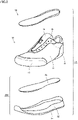
- Fig. 1 is a perspective view of a shoe according to the first embodiment.
- Fig. 2 is an exploded perspective view of the shoe shown in Fig. 1 .
- First, the configuration of a shoe 1A according to the present embodiment will be described with reference to Figs. 1 and 2 .
- the shoe 1A includes an upper 10, a shoe sole 20A, and a sockliner 30.
- the upper 10 has a shape that covers the entire portion on the instep side of a foot inserted into the shoe.
- the shoe sole 20A is located below the upper 10 so as to cover the sole of a foot.
- the sockliner 30 is accommodated inside the upper 10 so as to cover the inner bottom surface of the upper 10.
- the upper 10 includes an upper body 11, a shoe tongue 12, a toe-side reinforcing portion 13, a heel-side reinforcing portion 14, an eyelet reinforcing portion 15, and a shoelace 16.
- the shoe tongue 12, the toe-side reinforcing portion 13, the heel-side reinforcing portion 14, the eyelet reinforcing portion 15, and the shoelace 16 each are fixed or attached to the upper body 11.
- the upper body 11 has a lower portion provided with a lower opening covered with the shoe sole 20A.
- the upper body 11 has an upper portion provided with an upper opening through which an upper portion of an ankle and a part of the instep of a foot are exposed.
- the shoe tongue 12 is fixed to the upper body 11 by sewing, welding, bonding, or a combination thereof so as to cover a portion of the upper opening provided in the upper body 11 through which a part of the instep of a foot is exposed.
- woven fabric, knitted fabric, synthetic leather, resin, or the like may be used.
- a double raschel warp knitted fabric with a polyester yarn knitted therein may be used.
- the toe-side reinforcing portion 13 and the heel-side reinforcing portion 14 are provided for reinforcing the portions of the upper body 11 that cover a toe and a heel, respectively, of a foot and that are particularly required to have durability. Also, the toe-side reinforcing portion 13 and the heel-side reinforcing portion 14 are positioned so as to cover the outer surface of the upper body 11 that corresponds to these portions.
- the eyelet reinforcing portion 15 is provided for reinforcing the peripheral edge of the upper opening, which is provided in the upper body 11 and through which a part of the instep of a foot is exposed (the peripheral edge is specifically a portion to which the shoelace 16 is attached).
- the peripheral edge is also a portion particularly required to have durability similarly to the toe-side reinforcing portion 13 and the heel-side reinforcing portion 14.
- the eyelet reinforcing portion 15 is positioned so as to cover the outer surface of the upper body 11 that corresponds to the above-mentioned portion.
- the toe-side reinforcing portion 13, the heel-side reinforcing portion 14, and the eyelet reinforcing portion 15 each are made, for example, of woven fabric, knitted fabric, synthetic leather, resin, or the like fixed to the outer surface of the upper body 11 by sewing, welding, bonding, or a combination thereof.
- the shoelace 16 is formed of a string-shaped member for pulling, close in the foot width direction, the peripheral edge of the upper opening which is provided in the upper body 11 and through which a part of the instep of a foot is exposed.
- the shoelace 16 is passed through a plurality of holes provided in the peripheral edge of the upper opening.
- the shoe sole 20A includes an outsole 21, a midsole 22, and an insole 23. Among them, the midsole 22 and the insole 23 correspond to a sole body.
- the outsole 21 and the midsole 22 are integrally formed to have a substantially flat shape as a whole.
- the outsole 21 has a lower surface including a ground contact surface 21b (see Figs. 3 , 4 , and the like).
- the midsole 22 is located above the outsole 21.
- the insole 23 is attached to the upper body 11 so as to cover the above-mentioned lower opening of the upper body 11. More specifically, the insole 23 is fixed by sewing to the lower edge of the upper body 11. Further, the insole 23 is fixed to the upper surface of the midsole 22 by bonding, welding, or the like.
- the insole 23 is formed for example of: woven fabric, knitted fabric, or nonwoven fabric made of synthetic resin fibers such as polyester; or a resin-made foam material containing a resin material as a main component, and a foaming agent and a crosslinking agent as sub-components.
- the insole 23, which is a member constituting a part of the shoe sole 20A as described above, is not indispensable and may not be provided.
- the shoe sole 20A is formed of the outsole 21 and the midsole 22 as a sole body.
- the sockliner 30 is accommodated inside the upper 10 as described above, and is detachably attached onto the inner bottom surface of the upper 10 or fixed to the inner bottom surface of the upper 10 by welding, bonding, or the like.
- the sockliner 30 is formed of: woven fabric, knitted fabric, or nonwoven fabric made of synthetic resin fibers such as polyester; or a resin-made foam material containing a resin material as a main component, and a foaming agent and a crosslinking agent as sub-components.
- the sockliner 30 is provided for the purpose of achieving an excellent fit on a foot.
- the sockliner 30 is not indispensable and may not be provided.
- Fig. 3 is a side view of a shoe sole (excluding an insole) shown in Fig. 1 as seen from the lateral foot side.
- Figs. 4 and 5 are a bottom view and a top view, respectively, of the shoe sole (excluding an insole) shown in Fig. 1 .
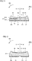
- Fig. 6 is a cross-sectional view taken along a line VI-VI shown in Fig. 5 . The following describes the configuration of the shoe sole 20A according to the present embodiment in greater detail with reference to Figs. 3 to 6 .
- the shoe sole 20A includes the insole 23 in addition to the outsole 21 and the midsole 22.
- the insole 23 is formed of a sufficiently thin member that is generally 2 mm or less in thickness.
- the insole 23 has relatively less influence on the shock absorbing performance, the stability, the fit on a foot, and the like of the shoe sole 20A on contact with the ground. Rather, the shock absorbing performance, the stability, the fit on a foot, and the like are determined mainly by the outsole 1 and the midsole 22.
- the following basically describes specifically the outsole 21 and the midsole 22 in the shoe sole 20A.
- the shoe sole 20A includes the outsole 21 and the midsole 22 as described above.
- the outsole 21 has an upper surface 21a and a ground contact surface 21b as a lower surface, and constitutes a lower portion of the shoe sole 20A.
- the midsole 22 has an upper surface 22a and a lower surface 22b, and constitutes an upper portion of the shoe sole 20A.
- the shoe sole 20A is shaped such that a peripheral edge portion of the upper surface 22a of the midsole 22 that defines the upper surface of the shoe sole 20A protrudes as compared with the surround area.
- the upper surface 22a has a recessed portion.
- the recessed portion serves to receive the upper 10 and the insole 23 therein.
- the upper surface 22a corresponding to the bottom surface of the recessed portion and excluding the peripheral edge portion has a smooth curved surface shape so as to fit to the shape of the sole of a foot.
- the outsole 21 is preferably excellent in wear resistance and grip performance. From this viewpoint, the outsole 21 is formed using a member made of a material, for example, containing a rubber material as a main component and a plasticizer, a reinforcing agent, and a crosslinking agent as sub-components.
- the outsole 21 is generally formed of a member that is higher in Young's modulus and harder than the midsole 22.
- a tread pattern is provided on the ground contact surface 21b of the outsole 21 by forming protrusions and recesses on the exposed surface thereof in order to improve the grip performance.
- the tread pattern and the shape of the outsole 21 may be designed as appropriate according to the intended use of the shoe 1A, and the shapes shown in Figs. 3 and 4 are provided merely by way of example.
- the midsole 22 preferably excellently absorbs shock while having an appropriate strength.
- the midsole 22 is formed, for example, using: a resin material as a main component; and a resin-made foam material containing a foaming agent and a crosslinking agent as sub-components.
- the midsole 22 may be formed using a rubber-made foam material containing: a rubber material as a main component; and a plasticizer, a foaming agent, a reinforcing agent, and a crosslinking agent as sub-components.
- thermoplastic resin ethylene-vinyl acetate (EVA) copolymer may be suitably used.
- thermosetting resin for example, polyurethane (PU) may be suitably used.
- rubber material for example, butadiene rubber may be suitably used.
- the midsole 22 is generally formed of a member that is lower in Young's modulus and softer than the outsole 21. Note that the midsole 22 may include various types of shock absorbing parts or reinforcing parts in prescribed portions.
- the shoe sole 20A includes a forefoot portion R1 that supports a toe portion and a ball portion of a foot, a midfoot portion R2 that supports an arch portion of the foot, and a rearfoot portion R3 that supports a heel portion of the foot.
- the forefoot portion R1, the midfoot portion R2, and the rearfoot portion R3 are positioned to be connected in the front-rear direction of the shoe sole 20A.
- the midsole 22 includes a low hardness portion 24 made of a foam material having relatively low hardness and a high hardness portion 25 made of a foam material having relatively high hardness.
- the low hardness portion 24 and the high hardness portion 25 are bonded to each other and thereby integrally formed.
- a foam material with low hardness is low in hardness (i.e., soft), and thus, is low in compressive rigidity and more likely to deform.
- a foam material with high hardness is high in hardness (i.e., hard), and thus, is high in compressive rigidity and less likely to deform.
- the low hardness portion 24 receives a load to thereby deform more significantly than the high hardness portion 25, and thus, mainly serves to absorb the impact received when the foot contacts the ground.
- the high hardness portion 25 in the midsole 22 receives a load but does not significantly deform as compared with the low hardness portion 24, and thereby, mainly serves to ensure the stability on contact with the ground.
- a shoe sole having a high rigidity portion or a high hardness portion disposed at a prescribed position in a lower layer portion of a midsole made of a foam material In the case of the shoe sole having the above-described configuration, the high rigidity portion or the high hardness portion is provided in the midsole, thereby enhancing the stability on contact with the ground. Further, a low rigidity portion or a low hardness portion is to be provided in an upper layer portion of the midsole so as to cover the high rigidity portion or the high hardness portion, thereby enabling a relatively excellent fit on a foot.
- the low rigidity portion or the low hardness portion provided in the upper layer portion of the midsole so as to cover the high rigidity portion or the high hardness portion may excessively deform under load on contact with the ground. In that case, consequently, the desired stability may not be sufficiently achieved.
- the low hardness portion 24 is provided in the midsole 22 so as to define the entire area of the lower surface of the midsole 22 while the high hardness portion 25 is disposed only in a specific region of the region located above the low hardness portion 24 in the midsole 22.
- the high hardness portion 25 is disposed in a specific region (a region indicated by oblique lines in Fig. 5 ) in the upper layer portion L1 (see Fig. 6 ) of the midsole 22 so as to define a part of the upper surface 22a of the midsole 22.
- the low hardness portion 24 is disposed: in a region excluding the above-mentioned specific region (the region other than the region indicated by oblique lines in Fig. 5 ) from the upper layer portion L1 (see Fig. 6 ) of the midsole 22; and entirely in the lower layer portion L2 (see Fig. 6 ) of the midsole 22 that includes the region located below the above-mentioned specific region.
- the above-mentioned specific region is located in a portion on the medial foot side (on the side indicated by a reference character S1 in the figure) in the midsole 22, and more specifically located to extend in: a portion on the medial foot side in the forefoot portion R1 that includes a part Q1 for supporting a big toe; a portion on the medial foot side in the midfoot portion R2; and a portion on the medial foot side in the rearfoot portion R3.
- the portion on the medial foot side in the rearfoot portion R3 includes a portion on the medial foot side in the rearfoot portion R3 that includes a part Q3 for supporting a heel bone.
- the high hardness portion 25 is disposed almost entirely in a portion on the medial foot side in the midsole 22, which excludes a toe side portion from a portion on the upper layer portion L1 side.
- the low hardness portion 24 is disposed in a remaining portion of the midsole 22.
- the shoe sole 20A according to the present embodiment configured as described above and the shoe 1A including the shoe sole 20A can suppress occurrence of an overpronation in which the heel portion collapses inward more than necessary on contact with the ground (an excessive collapse of the heel portion in the direction indicated by an arrow AR1 shown in Fig. 6 ).
- the sole of each foot can be stably supported at the portion on the medial foot side.
- the pressure acting on the midsole 22 can be dispersed to thereby allow suppression of excessive deformation of the midsole 22, with the result that occurrence of an overpronation can be suppressed.
- the shoe sole 20A according to the above-described present embodiment and the shoe 1A including the shoe sole 20A can stably support the sole of each foot at the portion on the medial foot side as described above.
- the pressure acting on the midsole 22 can be dispersed to thereby allow suppression of excessive deformation of the midsole 22. Accordingly, when a person with pes planovalgus wears the shoes 1A according to the present embodiment, concentration of a load on the medial foot side portion of each foot on contact with the ground can be avoided.
- the hardness of the low hardness portion 24 for example, its Asker C hardness is preferably 20 degrees or more and 70 degrees or less, and more preferably 40 degrees or more and 60 degrees or less.
- the hardness of the high hardness portion 25 for example, its Asker C hardness is preferably 60 degrees or more and 85 degrees or less on the condition that the high hardness portion 25 is higher in Asker C hardness than the low hardness portion 24.
- the boundary between the low hardness portion 24 and the high hardness portion 25 can be made hard to be felt by the sole of each foot, to thereby enable a more excellent fit on a foot.
- the difference between the Asker C hardness of the high hardness portion 25 and the Asker C hardness of the low hardness portion 24 is preferably 8 degrees or more, and more preferably 10 degrees or more.
- the boundary between the low hardness portion 24 and the high hardness portion 25 can be made hard to be felt by the sole of each foot, to thereby enable a more excellent fit on a foot.
- the high hardness portion 25 may have a configuration in which its thickness t is a maximum at the position closest to the edge portion on the medial foot side in the midsole 22 in the foot width direction, and this thickness decreases with distance from the edge portion in the foot width direction (i.e., decreases toward the lateral foot side).
- the thickness t of the high hardness portion 25 does not necessarily have to change in the foot width direction, but may be uniform.
- the shoe 1A since the shoe 1A includes the insole 23 and the sockliner 30, the boundary between the low hardness portion 24 and the high hardness portion 25 can be made hard to be felt by the sole of each foot.
- the insole 23 and the sockliner 30 do not necessarily have to be provided, but one or both of the insole 23 and the sockliner 30 may not be provided in the shoe.
- the low hardness portion 24 and the high hardness portion 25 are bonded to each other as described above, so that the midsole 22 is integrally formed.
- Such a configuration can be manufactured, for example, in such a way that a foam material of the low hardness portion 24 and a foam material of the high hardness portion 25 are superimposed on each other and press-molded and then welded to each other. Therefore, by using this manufacturing method, the shoe sole 20A can be readily and inexpensively manufactured.
- the above-described manufacturing method does not necessarily have to be used for manufacturing the shoe sole 20A, but a foam material of the low hardness portion 24 and a foam material of the high hardness portion 25 may be bonded, for example, by adhesion and the like through an adhesive layer, or the shoe sole 20A may be manufactured by two-color molding that is a type of injection molding.
- the melting point of the material of the low hardness portion 24 is preferably the same as the melting point of the material of the high hardness portion 25.
- These melting points are preferably 50 °C or more and 200 °C or less, and more preferably 50 °C or more and 140 °C or less.
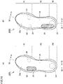
- Figs. 7(A), 7(B) , 8(A), and 8(B) are top views of shoe soles (each excluding an insole) of shoes according to the first, second, third, and fourth modifications, respectively.
- shoe soles 20A1 to 20A4 according to the first to fourth modifications based on the above-described first embodiment.
- each of the shoe soles 20A1 to 20A4 according to the first to fourth modifications is provided in the shoe 1A.
- a specific region of the midsole 22 where the high hardness portion 25 is provided is reduced as compared with the above-described shoe sole 20A. Also in the shoe sole 20A1 according to the present modification, the specific region is located in a portion on the medial foot side in the midsole 22.
- a specific region of the midsole 22 where the high hardness portion 25 is provided is reduced as compared with the above-described shoe sole 20A. Also in the shoe sole 20A2 according to the present modification, the specific region is located in a portion on the medial foot side in the midsole 22.
- a specific region of the midsole 22 where the high hardness portion 25 is provided is reduced as compared with the above-described shoe sole 20A. Also in the shoe sole 20A3 according to the present modification, the specific region is located in a portion on the medial foot side in the midsole 22.
- the specific region is located mainly in: a portion on the medial foot side in the forefoot portion R1 that includes the part Q1 for supporting a big toe; and a portion on the medial foot side in the rearfoot portion R3, in which these portions of the forefoot portion R1 and the rearfoot portion R3 are independent of each other.
- the portion on the medial foot side in the rearfoot portion R3 includes a portion on the medial foot side in the part Q3 for supporting a heel bone in the rearfoot portion R3.
- the high hardness portion 25 is disposed only in the above-described two portions on the medial foot side and on the upper layer portion L1 side in the midsole 22, and the low hardness portion 24 is disposed in the remaining portion of the midsole 22.
- a specific region of the midsole 22 where the high hardness portion 25 is provided is enlarged as compared with the above-described shoe sole 20A.
- the specific region is located not only in the portion on the medial foot side in the midsole 22 but also partially located in the portion on the lateral foot side in the midsole 22.
- the shoe soles 20A1 to 20A4 according to the first to fourth modifications and the shoe 1A including one of the shoe soles 20A1 to 20A4 can also achieve the effect according to the above-described first embodiment though the resulting effect is different to some degree.
- a shoe sole that is particularly suitable for a person more likely to suffer from an overpronation and a person with pes planovalgus, that is excellent in stability on contact with the ground, that enables an excellent fit on a foot, and that is reduced in weight; and a shoe including the shoe sole.
- Figs. 9 to 11 are cross-sectional views of shoe soles (each excluding an insole) of shoes according to the respective fifth to seventh modifications.
- shoe soles 20A5 to 20A7 according to the fifth to seventh modifications based on the above-described first embodiment.
- each of the shoe soles 20A5 to 20A7 according to the fifth to seventh modifications is provided in the shoe 1A.
- the configuration of the midsole 22 is different from that of the above-described shoe sole 20A.
- the configuration of the specific region in the midsole 22 where the high hardness portion 25 is provided is also different from that in the case of the above-described shoe sole 20A.
- the low hardness portion 24 is provided in the midsole 22 so as to define the entire area of the lower surface of the midsole 22, and the high hardness portion 25 is disposed only in a specific region of the region located above the low hardness portion 24 in the midsole 22. Therefore, the above-described effect according to the first embodiment is achieved.
- the lower midsole portion 221 and the low hardness portion 24 of the upper midsole portion 222 may be formed of different types of foam materials or may be formed of the same type of foam material.
- the midsole 22 can have various functions by such a combination of the foam materials.
- the shoe sole 20A6 according to the sixth modification is different in configuration from the shoe sole 20A5 according to the above-described fifth modification only in that the specific region of the midsole 22 where the high hardness portion 25 is provided is different.
- the specific region of the midsole 22 where the high hardness portion 25 is provided is provided only in the portion on the lower surface side in the upper midsole portion 222, but not provided in the portion on the upper surface side in the upper midsole portion 222. Accordingly, the high hardness portion 25 is to be embedded in the midsole 22 in the thickness direction, and the upper surface and the lower surface of the midsole 22 are to be defined by the low hardness portion 24.
- the position where the specific region is formed is the same as that in the case of the above-described shoe sole 20A.
- the low hardness portion 24 is located above the high hardness portion 25.
- T1 the minimum value of the thickness dimension of the midsole 22
- T2 the maximum value of the thickness of the portion of the midsole 22 that is located below the high hardness portion 25
- T1 and T2 satisfy the condition of T2 ⁇ (1/2) ⁇ T1.
- the portion of the low hardness portion 24 that is located above the high hardness portion 25 is sufficiently thin in thickness, so that the stability on contact with the ground can be ensured.
- the thickness of the portion of the low hardness portion 24 that is located above the high hardness portion 25 may be less than one-fourth of the value of T1.
- the low hardness portion 24 is provided in the midsole 22 so as to define the entire area of the lower surface of the midsole 22, and the high hardness portion 25 is disposed only in a specific region of the region located above the low hardness portion 24 in the midsole 22. Therefore, the effect according to the above-described first embodiment is achieved.
- the lower midsole portion 221 and the low hardness portion 24 of the upper midsole portion 222 may be formed of different types of foam materials or may be formed of the same type of foam material.
- the midsole 22 can have various functions by such a combination of the foam materials.
- the shoe sole 20A7 according to the seventh modification is different in configuration from the shoe sole 20A5 according to the above-described fifth modification only in that the specific region of the midsole 22 where the high hardness portion 25 is provided is different.
- the specific region of the midsole 22 where the high hardness portion 25 is provided is provided only in the portion on the upper surface side in the lower midsole portion 221, but not provided in the portions on the lower surface side in the upper midsole portion 222 and the lower midsole portion 221. Accordingly, the high hardness portion 25 is to be embedded in the midsole 22 in the thickness direction, and the upper surface and the lower surface of the midsole 22 are to be defined by the low hardness portion 24.
- the position where the specific region is formed is the same as that in the case of the above-described shoe sole 20A.
- the low hardness portion 24 is located above the high hardness portion 25.
- T1 the minimum value of the thickness dimension of the midsole 22
- T2 the maximum value of the thickness of the portion of the midsole 22 that is located below the high hardness portion 25
- T1 and T2 satisfy the condition of T2 ⁇ (1/2) ⁇ T1.
- the portion of the low hardness portion 24 that is located above the high hardness portion 25 is sufficiently thin in thickness, so that the stability on contact with the ground can be ensured.
- the thickness of the portion of the low hardness portion 24 that is located above the high hardness portion 25 may be less than one-fourth of the value of T1.
- the low hardness portion 24 is provided in the midsole 22 so as to define the entire area of the lower surface of the midsole 22, and the high hardness portion 25 is disposed only in a specific region of the region located above the low hardness portion 24 in the midsole 22. Therefore, the effect according to the above-described first embodiment is achieved.
- the low hardness portion 24 of the lower midsole portion 221 and the upper midsole portion 222 may be formed of different types of foam materials or may be formed of the same type of foam material.
- the midsole 22 can have various functions by such a combination of the foam materials.
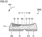
- Figs. 12 and 13 are cross-sectional views of shoe soles of shoes according to the eighth and ninth modifications, respectively.
- the following describes shoe soles 20A8 and 20A9 according to the eighth and ninth modifications, respectively, based on the above-described first embodiment.
- each of the shoe soles 20A8 and 20A9 according to the eighth and ninth modifications is provided in the shoe 1A.
- the shoe sole 20A8 according to the eighth modification is different from the above-described shoe sole 20A in configurations of the midsole 22 and the insole 23, and accordingly, is significantly different from the above-described shoe sole 20A in configuration of the sole body where the low hardness portion 24 and the high hardness portion 25 are provided.
- the midsole 22 is entirely formed of the low hardness portion 24 made of a foam material having relatively low hardness
- the insole 23 is formed of the low hardness portion 24 made of a foam material having relatively low hardness and the high hardness portion 25 made of a foam material having relatively high hardness.
- the low hardness portion 24 is provided in the midsole 22 so as to define the entire area of the lower surface of the midsole 22, and the high hardness portion 25 is disposed only in a specific region of the region of the insole 23 that is located above the low hardness portion 24 provided in the midsole 22.
- the position where the specific region is formed is the same as that in the case of the above-described shoe sole 20A.
- the effect according to the above-described first embodiment is achieved also in the case of the shoe sole 20A8 according to the present modification.
- a shoe sole that is particularly suitable for a person more likely to suffer from an overpronation and a person with pes planovalgus, that is excellent in stability on contact with the ground, that enables an excellent fit on a foot, and that is reduced in weight; and a shoe including the shoe sole.
- the insole 23 is generally formed of a sufficiently thin member as described above, and therefore, the insole 23 has relatively small influence on the shock absorbing performance, the stability, the fit on a foot, and the like of the shoe sole 20A8 on contact with the ground.
- the high hardness portion 25 provided in the insole 23 is configured to have relatively high hardness, or if the insole 23 itself is formed thicker than usual to thereby increase the thickness of the high hardness portion 25, the insole 23 can exert relatively significant influence on the shock absorbing performance, the stability, the fit on a foot, and the like of the shoe sole 20A8.
- the effect according to the above-described first embodiment can be achieved as described above.
- the present modification has exemplified the case where the low hardness portion 24 of the insole 23 is formed of a foam material having relatively low hardness, but the low hardness portion 24 may be formed of woven fabric, knitted fabric, synthetic leather, or the like.
- the configuration of the midsole 22 is the same but the configuration of the insole 23 is different therebetween.
- the configuration of the sole body where the low hardness portion 24 and the high hardness portion 25 are provided is different from that in the case of the above-described shoe sole 20A.
- the insole 23 is formed of the low hardness portion 24 made of a foam material having relatively low hardness and the high hardness portion 25 made of a foam material having relatively high hardness, and the insole 23 is disposed above the midsole 22 and bonded thereto.
- the high hardness portion 25 provided in the midsole 22 and the high hardness portion provided in the insole 23 are integrated with each other.
- the position where the specific region is formed is the same as that in the case of the above-described shoe sole 20A.
- the shoe sole 20A9 according to the present modification also has substantially the same configuration as that in the case of the above-described shoe sole 20A.
- the low hardness portion 24 is provided in the midsole 22 so as to define the entire area of the lower surface of the midsole 22, and the high hardness portion 25 is disposed only in a specific region of the region located above the low hardness portion 24 in each of the midsole 22 and the insole 23. Therefore, the effect according to the above-described first embodiment is achieved.
- Fig. 14 is a top view of a shoe sole (excluding an insole) of a shoe according to the second embodiment
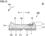
- Fig. 15 is a cross-sectional view taken along a line XV-XV shown in Fig. 14 .
- the following describes a shoe sole 20B according to the present embodiment and a shoe 1B including the shoe sole 20B with reference to Figs. 14 and 15 .
- the shoe 1B according to the present embodiment includes an upper and a sockliner having the same configurations as those in the shoe 1A according to the above-described embodiment.
- the shoe sole 20B according to the present embodiment includes the midsole 22 including: the low hardness portion 24 made of a foam material having relatively low hardness; and the high hardness portion 25 made of a foam material having relatively high hardness. Also, the low hardness portion 24 and the high hardness portion 25 are bonded to each other and thereby integrally formed.
- the high hardness portion 25 is disposed in a specific region (a region indicated by oblique lines in Fig. 14 ) of the upper layer portion L1 (see Fig. 15 ) in the midsole 22 so as to define a part of the upper surface 22a of the midsole 22.
- the low hardness portion 24 is disposed: in the region excluding the specific region (a region other than the region indicated by oblique lines in Fig. 14 ) from the upper layer portion L1 (see Fig. 15 ) in the midsole 22; and entirely in the lower layer portion L2 (see Fig. 15 ) of the midsole 22 that includes the region located below the above-mentioned specific region, so as to define the remaining portion of the upper surface 22a of the midsole 22 and the lower surface 22b of the midsole 22.
- the above-described specific region is located in the portion on the lateral foot side (on the side indicated by the reference character S2 in the figure) in the midsole 22, and more specifically located to extend in: the portion on the lateral foot side in the forefoot portion R1 that includes a part Q2 for supporting a little toe; the portion on the lateral foot side in the midfoot portion R2; and the portion on the lateral foot side in the rearfoot portion R3.
- the portion on the lateral foot side in the rearfoot portion R3 includes the portion on the lateral foot side in the part Q3 for supporting a heel bone in the rearfoot portion R3.
- the high hardness portion 25 is disposed almost entirely in a portion on the lateral foot side in the midsole 22, which excludes a toe side portion from the portion on the upper layer portion L1 side, and the low hardness portion 24 is disposed in the remaining portion of the midsole 22.
- the shoe sole 20B according to the present embodiment configured as described above and the shoe 1B including the shoe sole 20B can suppress occurrence of an underpronation in which the heel portion does not sufficiently collapse inward on contact with the ground (insufficient collapse of the heel portion in the direction indicated by the arrow AR1 shown in Fig. 15 ).
- the sole of each foot can be stably supported at the portion on the lateral foot side.
- the pressure acting on the midsole 22 can be dispersed to thereby allow suppression of excessive deformation of the midsole 22, with the result that the occurrence of underpronation can be suppressed.
- the shoe sole 20B according to the above-described present embodiment and the shoe 1B including the shoe sole 20B can stably support the sole of each foot at the portion on the lateral foot side.
- the pressure acting on the midsole 22 can be dispersed to thereby allow suppression of excessive deformation of the midsole 22. Accordingly, when a person with bowlegs wears the shoes 1B according to the present embodiment, concentration of a load on the lateral foot side portion of each foot on contact with the ground can be avoided.
- the low hardness portion 24 is located below the high hardness portion 25, so that the high hardness portion 25 itself has a relatively reduced thickness.
- the high hardness portion 25 is formed of a foam material similarly to the low hardness portion 24.
- the shoe sole 20B according to the present embodiment and the shoe 1B including the shoe sole 20B can provide: a shoe sole that is particularly suitable for a person more likely to suffer from an underpronation and a person with bowlegs, that is excellent in stability on contact with the ground, that enables an excellent fit on a foot, and that is reduced in weight; and a shoe including the shoe sole.
- the boundary between the low hardness portion 24 and the high hardness portion 25 can be made hard to be felt by the sole of each foot, to thereby enable a more excellent fit on a foot.
- the high hardness portion 25 may have a configuration in which its thickness t is a maximum at the position closest to the edge portion on the lateral foot side in the midsole 22 in the foot width direction, and this thickness decreases with distance from the edge portion in the foot width direction (i.e., decreases toward the medial foot side).
- the thickness t of the high hardness portion 25 does not necessarily have to change in the foot width direction, but the thickness t may be uniform.
- Figs. 16(A), 16(B) , 17(A), and 17(B) are top views of shoe soles (each excluding an insole) of shoes according to the tenth, eleventh, twelfth, and thirteenth modifications, respectively.
- shoe soles 20B1 to 20B4 according to the tenth to thirteenth modifications based on the above-described second embodiment.
- each of the shoe soles 20B1 to 20B4 according to the tenth to thirteenth modifications is provided in the shoe 1B.
- a specific region of the midsole 22 where the high hardness portion 25 is provided is reduced as compared with the above-described shoe sole 20B. Also in the shoe sole 20B1 according to the present modification, the specific region is located in the portion on the lateral foot side in the midsole 22.
- the above-mentioned specific region is located mainly in the portion on the lateral foot side in the forefoot portion R1 that includes the part Q2 for supporting a little toe.
- the high hardness portion 25 is disposed only in the above-described portion in a portion on the lateral foot side and on the upper layer portion L1 side in the midsole 22, and the low hardness portion 24 is disposed in the remaining portion of the midsole 22.
- the above-mentioned specific region is located mainly in the portion on the lateral foot side in the rearfoot portion R3.
- the portion on the lateral foot side in the rearfoot portion R3 includes the portion on the lateral foot side in the part Q3 for supporting a heel bone in the rearfoot portion R3.
- the high hardness portion 25 is disposed only in the above-described portion in a portion on the lateral foot side and on the upper layer portion L1 side in the midsole 22, and the low hardness portion 24 is disposed in the remaining portion of the midsole 22.
- the specific region of the midsole 22 where the high hardness portion 25 is provided is reduced as compared with the above-described shoe sole 20B. Also in the shoe sole 20B3 according to the present modification, the specific region is located in the portion on the lateral foot side in the midsole 22.
- the high hardness portion 25 is disposed only in the above-described two portions on the lateral foot side and on the upper layer portion L1 side in the midsole 22, and the low hardness portion 24 is disposed in the remaining portion of the midsole 22.
- a specific region of the midsole 22 where the high hardness portion 25 is provided is enlarged as compared with the above-described shoe sole 20B.
- the specific region is located not only in the portion on the lateral foot side in the midsole 22 but also partially located in the portion on the medial foot side in the midsole 22.
- the high hardness portion 25 is disposed in: the almost entire area on the lateral foot side in the midsole 22 that excludes the toe side portion from the portion on the upper layer portion L1 side; and the above-described portion in the portion on the medial foot side and on the upper layer portion L1 side. Also, the low hardness portion 24 is disposed in the remaining portion of the midsole 22.
- the shoe soles 20B1 to 20B4 according to the tenth to thirteenth modifications and the shoe 1B including one of the shoe soles 20B1 to 20B4 can also achieve the effect according to the above-described second embodiment though the resulting effect is different to some degree.
- a shoe sole that is particularly suitable for a person more likely to suffer from an underpronation and a person with bowlegs, that is excellent in stability on contact with the ground, that enables an excellent fit on a foot, and that is reduced in weight; and a shoe including the shoe sole.
- Fig. 18 is a top view of a shoe sole (excluding an insole) of a shoe according to the third embodiment
- Fig. 19 is a cross-sectional view taken along a line XIX-XIX shown in Fig. 18
- the following describes a shoe sole 20C according to the present embodiment and a shoe 1C including the shoe sole 20C with reference to Figs. 18 and 19 .
- the shoe 1C according to the present embodiment includes an upper and a sockliner having the same configurations as those of the shoe 1A according to the above-described embodiment.
- the high hardness portion 25 is disposed in a specific region (a region indicated by oblique lines in Fig. 18 ) of the upper layer portion L1 (see Fig. 19 ) in the midsole 22 so as to define a part of the upper surface 22a of the midsole 22.
- the low hardness portion 24 is located below the high hardness portion 25, so that the high hardness portion 25 itself has a relatively reduced thickness.
- the high hardness portion 25 is formed of a foam material similarly to the low hardness portion 24.
- the sole body may include a midsole.
- each of the low hardness portion and the high hardness portion may be provided in the midsole.
- the low hardness portion and the high hardness portion may be bonded to each other such that the midsole is integrally formed.
- the high hardness portion may be disposed in the specific region of an upper layer portion of the midsole to define a part of an upper surface of the midsole.
- the low hardness portion may be disposed to extend: in a region excluding the specific region from the upper layer portion of the midsole; and entirely in a lower layer portion of the midsole that includes a region located below the specific region, so as to define a remaining portion of the upper surface of the midsole and a lower surface of the midsole.
- the high hardness portion may be embedded in the midsole in a thickness direction.
- the low hardness portion may be disposed entirely in a region excluding the specific region from the midsole so as to define an upper surface and a lower surface of the midsole.
- the sole body may include a midsole and an insole.
- the high hardness portion may be provided in the insole, and the low hardness portion may be provided in the midsole.
- the specific region is located in a portion on a medial foot side in the sole body.
- the specific region may be located in a portion on the medial foot side in the rearfoot portion.
- the specific region may be located in: a portion on the medial foot side in the forefoot portion, the portion including a part for supporting a big toe; and a portion on the medial foot side in the rearfoot portion, in which the specific region in the forefoot portion and the specific region in the rearfoot portion may be independent of each other.
- the specific region may be located to extend in: a portion on the medial foot side in the forefoot portion, the portion including a part for supporting a big toe; a portion on the medial foot side in the midfoot portion; and a portion on the medial foot side in the rearfoot portion.
- the specific region may be located to extend in: a portion on the medial foot side in the forefoot portion, the portion including a part for supporting a big toe; a portion on the medial foot side in the midfoot portion; a portion on the medial foot side in the rearfoot portion; and a portion on a lateral foot side in the rearfoot portion.
- a thickness of the high hardness portion may decrease toward the lateral foot side.
- the specific region is located in a portion on a lateral foot side in the sole body.
- the specific region may be located to extend in: a portion on the lateral foot side in the forefoot portion, the portion including a part for supporting a little toe; and a portion on the lateral foot side in the midfoot portion.
- a thickness of the high hardness portion may decrease toward the medial foot side.
- the specific region is located in a portion of the sole body that includes a part for supporting a heel bone.
- an Asker C hardness of the low hardness portion is 40 degrees or more and 60 degrees or less
- an Asker C hardness of the high hardness portion is 60 degrees or more and 85 degrees or less on a condition that the high hardness portion is higher in Asker C hardness than the low hardness portion.
- a shoe according to an aspect of the present disclosure includes: the shoe sole according to an aspect of the above-described present disclosure; and an upper located above the shoe sole.
- each of the boundary surface between the midsole and the outsole, and the boundary surface between the lower midsole portion and the upper midsole portion is formed in a planar shape, but these boundary surfaces each may be formed in a curved surface shape.
- shock absorbing parts each for performing a further shock absorbing function may be provided in a specific portion of the sole body formed of the midsole or formed of the insole in addition to the midsole.
- the characteristic configurations presented in the above-described first to third embodiments and the modifications thereof can be combined with one another.
- the configuration of the midsole and/or the insole in the thickness direction as in each of the fifth to ninth modifications based on the first embodiment may be applicable to the shoe sole according to the second or third embodiment and the shoe including the shoe sole.
- 1A to 1C shoe 10 upper, 11 upper body, 12 shoe tongue, 13 toe-side reinforcing portion, 14 heel-side reinforcing portion, 15 eyelet reinforcing portion, 16 shoelace, 20A, 20A1 to 20A9, 20B, 20B1 to 20B4, 20C shoe sole, 21 outsole, 21a upper surface, 21b ground contact surface, 22 midsole, 22a upper surface, 22b lower surface, 221 lower midsole portion , 222 upper midsole portion, 23 insole, 24 low hardness portion, 25 high hardness portion, 30 sockliner, L1 upper layer portion, L2 lower layer portion, Q1 part for supporting a big toe, Q2 part for supporting a little toe, Q3 part for supporting a heel bone, R1 forefoot portion, R2 midfoot portion, R3 rearfoot portion.
Landscapes
- Health & Medical Sciences (AREA)
- Epidemiology (AREA)
- General Health & Medical Sciences (AREA)
- Public Health (AREA)
- Chemical & Material Sciences (AREA)
- Engineering & Computer Science (AREA)
- Materials Engineering (AREA)
- Life Sciences & Earth Sciences (AREA)
- Wood Science & Technology (AREA)
- Footwear And Its Accessory, Manufacturing Method And Apparatuses (AREA)
Abstract
Description
- The present invention relates to a shoe sole and a shoe including the shoe sole.
- During walking or running, a phenomenon called a pronation occurs in which a heel portion of a foot collapses inward. This pronation is an original function of a human foot, by which, when the foot contacts the ground (strictly speaking, immediately after it contacts the ground), the heel portion properly collapses inward, thereby mitigating the impact applied to the foot upon contact with the ground.
- However, the degree to which the heel portion collapses varies among individuals. There are some who tend to suffer from a phenomenon called an overpronation in which the heel portion collapses inward more than necessary, and some who tend to suffer from a phenomenon called an underpronation in which the heel portion does not sufficiently collapse inward. Such an overpronation and an underpronation may cause problems with walking or running.
- Further, a person with what is called pes planovalgus tends to receive more load on a part on the medial foot side of his/her foot on contact with the ground. Also, a person with what is called bowlegs tends to receive more load on a part on the lateral foot side of his/her foot on contact with the ground. Accordingly, as they get older, their big toes or little toes may deform, which may also result in problems with walking or running.
- Thus, developments have conventionally been conducted for achieving a shoe sole provided with a high rigidity portion or a high hardness portion at a prescribed position of the shoe sole to enhance the stability of the wearer's foot on contact with the ground, to thereby adjust the collapsing degree of the heel portion and prevent excessive concentration of a load upon a part of the foot on the medial foot side or the lateral foot side.
- For example,
Japanese Patent Laying-Open No. 2000-225002 - Further,
Japanese Patent Laying-Open No. 2016-59555 - In addition, there is also known a shoe sole configured such that a high rigidity portion or a high hardness portion is provided at a prescribed position in a lower layer portion of a midsole made of a foam material, to thereby enhance the stability on contact with the ground.
-
- PTL 1:
Japanese Patent Laying-Open No. 2000-225002 - PTL 2:
Japanese Patent Laying-Open No. 2016-59555 - However, the shoe sole disclosed in
Japanese Patent Laying-Open No. 2000-225002 - Further, the shoe sole disclosed in
Japanese Patent Laying-Open No. 2016-59555 - Accordingly, an object of the present invention is to provide: a shoe sole that is excellent in stability on contact with the ground, that enables an excellent fit on a foot, and that is reduced in weight; and a shoe including the shoe sole.
- A shoe sole according to the present invention includes: a forefoot portion that supports a toe portion and a ball portion of a foot; a midfoot portion that supports an arch portion of the foot; and a rearfoot portion that supports a heel portion of the foot, in which the forefoot portion, the midfoot portion, and the rearfoot portion are connected in a front-rear direction. The shoe sole includes: an outsole provided with a ground contact surface; and a sole body located above the outsole. The sole body includes a low hardness portion made of a foam material having relatively low hardness, and a high hardness portion made of a foam material having relatively high hardness. The low hardness portion is provided to define an entire area of a lower surface of the sole body. The high hardness portion is disposed only in a specific region of a region located above the low hardness portion in the sole body.
- A shoe according to the present invention includes: the shoe sole according to the above-described present invention; and an upper located above the shoe sole.
- The present invention can provide: a shoe sole that is excellent in stability on contact with the ground, that enables an excellent fit on a foot, and that is reduced in weight; and a shoe including the shoe sole.
-
-
Fig. 1 is a perspective view of a shoe according to a first embodiment. -
Fig. 2 is an exploded perspective view of the shoe shown inFig. 1 . -
Fig. 3 is a side view of a shoe sole (excluding an insole) shown inFig. 1 as seen from a lateral foot side. -
Fig. 4 is a bottom view of the shoe sole shown inFig. 1 . -
Fig. 5 is a top view of the shoe sole (excluding an insole) shown inFig. 1 . -
Fig. 6 is a cross-sectional view taken along a line VI-VI shown inFig. 5 . -
Fig. 7 is a top view of each of shoe soles (each excluding an insole) of shoes according to first and second modifications. -
Fig. 8 is a top view of each of shoe soles (each excluding an insole) of shoes according to third and fourth modifications. -
Fig. 9 is a cross-sectional view of a shoe sole (excluding an insole) of a shoe according to a fifth modification. -
Fig. 10 is a cross-sectional view of a shoe sole (excluding an insole) of a shoe according to a sixth modification. -
Fig. 11 is a cross-sectional view of a shoe sole (excluding an insole) of a shoe according to a seventh modification. -
Fig. 12 is a cross-sectional view of a shoe sole of a shoe according to an eighth modification. -
Fig. 13 is a cross-sectional view of a shoe sole of a shoe according to a ninth modification. -
Fig. 14 is a top view of a shoe sole (excluding an insole) of a shoe according to a second embodiment. -
Fig. 15 is a cross-sectional view taken along a line XV-XV shown inFig. 14 . -
Fig. 16 is a top view of each of shoe soles (each excluding an insole) of shoes according to tenth and eleventh modifications. -
Fig. 17 is a top view of each of shoe soles (each excluding an insole) of shoes according to twelfth and thirteenth modifications. -
Fig. 18 is a top view of a shoe sole (excluding an insole) of a shoe according to a third embodiment. -
Fig. 19 is a cross-sectional view taken along a line XIX-XIX shown inFig. 18 . - Hereinafter, embodiments of the present invention will be described in detail with reference to the accompanying drawings. In the embodiments described below, the same or corresponding components are denoted by the same reference characters in accompanying drawings, and the description thereof will not be repeated.
- In the embodiments described below, in a plan view of a shoe, the extending direction of the straight line connecting both ends of a shoe sole in its longitudinal axis direction will be referred to as a front-rear direction. Also, in a plan view of a shoe, the direction orthogonal to the front-rear direction will be referred to as a foot width direction.
- In the front-rear direction, the direction from the end on which the portion of the shoe sole that supports a heel portion of a foot is located toward the end on which the portion of the shoe sole that supports a toe portion of the foot is located will be referred to as a front direction. Also, in the front-rear direction, the direction from the end on which the portion of the shoe sole that supports the toe portion of the foot is located toward the end on which the portion of the shoe sole that supports the heel portion of the foot is located will be referred to as a rear direction.
- With reference to the front end of the shoe sole, a first boundary position is defined at a position located at 40% of the dimension of the shoe sole from the front end in the front-rear direction, and a second boundary position is defined at a position located at 80% of the dimension of the shoe sole from the front end in the front-rear direction. In this case, a portion included between the front end and the first boundary position in the front-rear direction will be referred to as a forefoot portion of the shoe sole, a portion included between the first boundary position and the second boundary position in the front-rear direction will be referred to as a midfoot portion of the shoe sole, and a portion included between the second boundary position and the rear end of the shoe sole in the front-rear direction will be referred to as a rearfoot portion of the shoe sole.
- In this case, the forefoot portion of the shoe sole corresponds to a portion that supports a toe portion and a ball portion of a foot, the midfoot portion of the shoe sole corresponds to a portion that supports an arch portion of the foot, and the rearfoot portion of the shoe sole corresponds to a portion that supports a heel portion of the foot.
- Further, the medial side of the foot in anatomical position (that is, the side closer to the median) will be referred to as a medial foot side, and the side opposite to the medial side of the foot in anatomical position (that is, the side farther from the median) will be referred to as a lateral foot side.
- Further, the thickness direction means a direction orthogonal to the ground contact surface of the shoe sole unless otherwise specified, and the thickness means a dimension in the thickness direction unless otherwise specified.
-
Fig. 1 is a perspective view of a shoe according to the first embodiment.Fig. 2 is an exploded perspective view of the shoe shown inFig. 1 . First, the configuration of ashoe 1A according to the present embodiment will be described with reference toFigs. 1 and2 . - As shown in
Figs. 1 and2 , theshoe 1A includes an upper 10, a shoe sole 20A, and asockliner 30. The upper 10 has a shape that covers the entire portion on the instep side of a foot inserted into the shoe. The shoe sole 20A is located below the upper 10 so as to cover the sole of a foot. Thesockliner 30 is accommodated inside the upper 10 so as to cover the inner bottom surface of the upper 10. - The upper 10 includes an
upper body 11, ashoe tongue 12, a toe-side reinforcing portion 13, a heel-side reinforcing portion 14, aneyelet reinforcing portion 15, and ashoelace 16. Among them, theshoe tongue 12, the toe-side reinforcing portion 13, the heel-side reinforcing portion 14, theeyelet reinforcing portion 15, and theshoelace 16 each are fixed or attached to theupper body 11. - The
upper body 11 has a lower portion provided with a lower opening covered with the shoe sole 20A. Theupper body 11 has an upper portion provided with an upper opening through which an upper portion of an ankle and a part of the instep of a foot are exposed. Theshoe tongue 12 is fixed to theupper body 11 by sewing, welding, bonding, or a combination thereof so as to cover a portion of the upper opening provided in theupper body 11 through which a part of the instep of a foot is exposed. For theupper body 11 and theshoe tongue 12, for example, woven fabric, knitted fabric, synthetic leather, resin, or the like may be used. For shoes particularly required to be air permeable and lightweight, a double raschel warp knitted fabric with a polyester yarn knitted therein may be used. - The toe-
side reinforcing portion 13 and the heel-side reinforcing portion 14 are provided for reinforcing the portions of theupper body 11 that cover a toe and a heel, respectively, of a foot and that are particularly required to have durability. Also, the toe-side reinforcing portion 13 and the heel-side reinforcing portion 14 are positioned so as to cover the outer surface of theupper body 11 that corresponds to these portions. - The
eyelet reinforcing portion 15 is provided for reinforcing the peripheral edge of the upper opening, which is provided in theupper body 11 and through which a part of the instep of a foot is exposed (the peripheral edge is specifically a portion to which theshoelace 16 is attached). The peripheral edge is also a portion particularly required to have durability similarly to the toe-side reinforcing portion 13 and the heel-side reinforcing portion 14. Theeyelet reinforcing portion 15 is positioned so as to cover the outer surface of theupper body 11 that corresponds to the above-mentioned portion. - The toe-
side reinforcing portion 13, the heel-side reinforcing portion 14, and theeyelet reinforcing portion 15 each are made, for example, of woven fabric, knitted fabric, synthetic leather, resin, or the like fixed to the outer surface of theupper body 11 by sewing, welding, bonding, or a combination thereof. - The
shoelace 16 is formed of a string-shaped member for pulling, close in the foot width direction, the peripheral edge of the upper opening which is provided in theupper body 11 and through which a part of the instep of a foot is exposed. Theshoelace 16 is passed through a plurality of holes provided in the peripheral edge of the upper opening. When a foot is inserted into theupper body 11 and theshoelace 16 is tightened, theupper body 11 can be brought into close contact with the foot. - The shoe sole 20A includes an
outsole 21, amidsole 22, and aninsole 23. Among them, themidsole 22 and theinsole 23 correspond to a sole body. - The
outsole 21 and themidsole 22 are integrally formed to have a substantially flat shape as a whole. Theoutsole 21 has a lower surface including aground contact surface 21b (seeFigs. 3 ,4 , and the like). Themidsole 22 is located above theoutsole 21. - The
insole 23 is attached to theupper body 11 so as to cover the above-mentioned lower opening of theupper body 11. More specifically, theinsole 23 is fixed by sewing to the lower edge of theupper body 11. Further, theinsole 23 is fixed to the upper surface of themidsole 22 by bonding, welding, or the like. Theinsole 23 is formed for example of: woven fabric, knitted fabric, or nonwoven fabric made of synthetic resin fibers such as polyester; or a resin-made foam material containing a resin material as a main component, and a foaming agent and a crosslinking agent as sub-components. Note that theinsole 23, which is a member constituting a part of theshoe sole 20A as described above, is not indispensable and may not be provided. In this case, the shoe sole 20A is formed of theoutsole 21 and themidsole 22 as a sole body. - The
sockliner 30 is accommodated inside the upper 10 as described above, and is detachably attached onto the inner bottom surface of the upper 10 or fixed to the inner bottom surface of the upper 10 by welding, bonding, or the like. Thesockliner 30 is formed of: woven fabric, knitted fabric, or nonwoven fabric made of synthetic resin fibers such as polyester; or a resin-made foam material containing a resin material as a main component, and a foaming agent and a crosslinking agent as sub-components. Thesockliner 30 is provided for the purpose of achieving an excellent fit on a foot. Thesockliner 30 is not indispensable and may not be provided. -
Fig. 3 is a side view of a shoe sole (excluding an insole) shown inFig. 1 as seen from the lateral foot side.Figs. 4 and5 are a bottom view and a top view, respectively, of the shoe sole (excluding an insole) shown inFig. 1 .Fig. 6 is a cross-sectional view taken along a line VI-VI shown inFig. 5 . The following describes the configuration of the shoe sole 20A according to the present embodiment in greater detail with reference toFigs. 3 to 6 . - As described above, the shoe sole 20A according to the present embodiment includes the
insole 23 in addition to theoutsole 21 and themidsole 22. In this case, theinsole 23 is formed of a sufficiently thin member that is generally 2 mm or less in thickness. Thus, theinsole 23 has relatively less influence on the shock absorbing performance, the stability, the fit on a foot, and the like of the shoe sole 20A on contact with the ground. Rather, the shock absorbing performance, the stability, the fit on a foot, and the like are determined mainly by theoutsole 1 and themidsole 22. Thus, the following basically describes specifically theoutsole 21 and themidsole 22 in the shoe sole 20A. - As shown in
Figs. 3 to 6 , the shoe sole 20A includes theoutsole 21 and themidsole 22 as described above. Theoutsole 21 has anupper surface 21a and aground contact surface 21b as a lower surface, and constitutes a lower portion of the shoe sole 20A. Themidsole 22 has anupper surface 22a and alower surface 22b, and constitutes an upper portion of the shoe sole 20A. - The shoe sole 20A is shaped such that a peripheral edge portion of the
upper surface 22a of themidsole 22 that defines the upper surface of the shoe sole 20A protrudes as compared with the surround area. Thereby, theupper surface 22a has a recessed portion. The recessed portion serves to receive the upper 10 and theinsole 23 therein. Also, theupper surface 22a corresponding to the bottom surface of the recessed portion and excluding the peripheral edge portion has a smooth curved surface shape so as to fit to the shape of the sole of a foot. - The
outsole 21 is preferably excellent in wear resistance and grip performance. From this viewpoint, theoutsole 21 is formed using a member made of a material, for example, containing a rubber material as a main component and a plasticizer, a reinforcing agent, and a crosslinking agent as sub-components. - Thus, the
outsole 21 is generally formed of a member that is higher in Young's modulus and harder than themidsole 22. As shown inFigs. 3 and4 , a tread pattern is provided on theground contact surface 21b of theoutsole 21 by forming protrusions and recesses on the exposed surface thereof in order to improve the grip performance. The tread pattern and the shape of theoutsole 21 may be designed as appropriate according to the intended use of theshoe 1A, and the shapes shown inFigs. 3 and4 are provided merely by way of example. - The
midsole 22 preferably excellently absorbs shock while having an appropriate strength. From this viewpoint, themidsole 22 is formed, for example, using: a resin material as a main component; and a resin-made foam material containing a foaming agent and a crosslinking agent as sub-components. Alternatively, themidsole 22 may be formed using a rubber-made foam material containing: a rubber material as a main component; and a plasticizer, a foaming agent, a reinforcing agent, and a crosslinking agent as sub-components. - As the above-mentioned resin material, a thermoplastic resin and a thermosetting resin may be used. As a thermoplastic resin, ethylene-vinyl acetate (EVA) copolymer may be suitably used. As a thermosetting resin, for example, polyurethane (PU) may be suitably used. As the above-mentioned rubber material, for example, butadiene rubber may be suitably used.
- Thus, the
midsole 22 is generally formed of a member that is lower in Young's modulus and softer than theoutsole 21. Note that themidsole 22 may include various types of shock absorbing parts or reinforcing parts in prescribed portions. - As shown in
Figs. 3 to 5 , the shoe sole 20A includes a forefoot portion R1 that supports a toe portion and a ball portion of a foot, a midfoot portion R2 that supports an arch portion of the foot, and a rearfoot portion R3 that supports a heel portion of the foot. The forefoot portion R1, the midfoot portion R2, and the rearfoot portion R3 are positioned to be connected in the front-rear direction of the shoe sole 20A. - As shown in
Figs. 5 and6 , in the shoe sole 20A according to the present embodiment, themidsole 22 includes alow hardness portion 24 made of a foam material having relatively low hardness and ahigh hardness portion 25 made of a foam material having relatively high hardness. Thelow hardness portion 24 and thehigh hardness portion 25 are bonded to each other and thereby integrally formed. - In general, a foam material with low hardness is low in hardness (i.e., soft), and thus, is low in compressive rigidity and more likely to deform. On the other hand, a foam material with high hardness is high in hardness (i.e., hard), and thus, is high in compressive rigidity and less likely to deform.
- Accordingly, by providing the
low hardness portion 24 in themidsole 22, thelow hardness portion 24 receives a load to thereby deform more significantly than thehigh hardness portion 25, and thus, mainly serves to absorb the impact received when the foot contacts the ground. On the other hand, by providing thehigh hardness portion 25 in themidsole 22, thehigh hardness portion 25 receives a load but does not significantly deform as compared with thelow hardness portion 24, and thereby, mainly serves to ensure the stability on contact with the ground. - As described above, there is conventionally known a shoe sole having a high rigidity portion or a high hardness portion disposed at a prescribed position in a lower layer portion of a midsole made of a foam material. In the case of the shoe sole having the above-described configuration, the high rigidity portion or the high hardness portion is provided in the midsole, thereby enhancing the stability on contact with the ground. Further, a low rigidity portion or a low hardness portion is to be provided in an upper layer portion of the midsole so as to cover the high rigidity portion or the high hardness portion, thereby enabling a relatively excellent fit on a foot.
- However, when the above-described configuration is adopted, it is also conceivable that the low rigidity portion or the low hardness portion provided in the upper layer portion of the midsole so as to cover the high rigidity portion or the high hardness portion may excessively deform under load on contact with the ground. In that case, consequently, the desired stability may not be sufficiently achieved.
- In this regard, in the shoe sole 20A according to the present embodiment, the
low hardness portion 24 is provided in themidsole 22 so as to define the entire area of the lower surface of themidsole 22 while thehigh hardness portion 25 is disposed only in a specific region of the region located above thelow hardness portion 24 in themidsole 22. - More specifically, the
high hardness portion 25 is disposed in a specific region (a region indicated by oblique lines inFig. 5 ) in the upper layer portion L1 (seeFig. 6 ) of themidsole 22 so as to define a part of theupper surface 22a of themidsole 22. - On the other hand, so as to define the remaining portion of the
upper surface 22a of themidsole 22 and thelower surface 22b of themidsole 22, thelow hardness portion 24 is disposed: in a region excluding the above-mentioned specific region (the region other than the region indicated by oblique lines inFig. 5 ) from the upper layer portion L1 (seeFig. 6 ) of themidsole 22; and entirely in the lower layer portion L2 (seeFig. 6 ) of themidsole 22 that includes the region located below the above-mentioned specific region. - In the present embodiment, the above-mentioned specific region is located in a portion on the medial foot side (on the side indicated by a reference character S1 in the figure) in the
midsole 22, and more specifically located to extend in: a portion on the medial foot side in the forefoot portion R1 that includes a part Q1 for supporting a big toe; a portion on the medial foot side in the midfoot portion R2; and a portion on the medial foot side in the rearfoot portion R3. Also, the portion on the medial foot side in the rearfoot portion R3 includes a portion on the medial foot side in the rearfoot portion R3 that includes a part Q3 for supporting a heel bone. - In other words, in the present embodiment, the
high hardness portion 25 is disposed almost entirely in a portion on the medial foot side in themidsole 22, which excludes a toe side portion from a portion on the upper layer portion L1 side. Thelow hardness portion 24 is disposed in a remaining portion of themidsole 22. - The shoe sole 20A according to the present embodiment configured as described above and the
shoe 1A including the shoe sole 20A can suppress occurrence of an overpronation in which the heel portion collapses inward more than necessary on contact with the ground (an excessive collapse of the heel portion in the direction indicated by an arrow AR1 shown inFig. 6 ). In other words, when a person who is more likely to suffer from an overpronation wears theshoes 1A according to the present embodiment, the sole of each foot can be stably supported at the portion on the medial foot side. Thus, the pressure acting on themidsole 22 can be dispersed to thereby allow suppression of excessive deformation of themidsole 22, with the result that occurrence of an overpronation can be suppressed. - Further, the shoe sole 20A according to the above-described present embodiment and the
shoe 1A including the shoe sole 20A can stably support the sole of each foot at the portion on the medial foot side as described above. Thus, the pressure acting on themidsole 22 can be dispersed to thereby allow suppression of excessive deformation of themidsole 22. Accordingly, when a person with pes planovalgus wears theshoes 1A according to the present embodiment, concentration of a load on the medial foot side portion of each foot on contact with the ground can be avoided. - In addition, by adopting the above-described configuration, the
low hardness portion 24 is located below thehigh hardness portion 25, so that thehigh hardness portion 25 itself has a relatively reduced thickness. Also, thehigh hardness portion 25 is formed of a foam material similarly to thelow hardness portion 24. Thus, the fit on a foot is not impaired but an excellent fit on a foot can be achieved, and further, the shoe sole and the shoe can be reduced in weight. - In this way, the shoe sole 20A according to the present embodiment and the
shoe 1A including the shoe sole 20A can provide: a shoe sole that is particularly suitable for a person more likely to suffer from an overpronation and a person with pes planovalgus, that is excellent in stability on contact with the ground, that enables an excellent fit on a foot, and that is reduced in weight; and a shoe including the shoe sole. - As the hardness of the
low hardness portion 24, for example, its Asker C hardness is preferably 20 degrees or more and 70 degrees or less, and more preferably 40 degrees or more and 60 degrees or less. On the other hand, as the hardness of thehigh hardness portion 25, for example, its Asker C hardness is preferably 60 degrees or more and 85 degrees or less on the condition that thehigh hardness portion 25 is higher in Asker C hardness than thelow hardness portion 24. By satisfying these conditions, while ensuring the stability on contact with the ground, the boundary between thelow hardness portion 24 and thehigh hardness portion 25 can be made hard to be felt by the sole of each foot, to thereby enable a more excellent fit on a foot. Further, the difference between the Asker C hardness of thehigh hardness portion 25 and the Asker C hardness of thelow hardness portion 24 is preferably 8 degrees or more, and more preferably 10 degrees or more. - Further, as shown in
Fig. 6 , in the configuration in which a thickness t of thehigh hardness portion 25 decreases toward the lateral foot side in the edge portion of thehigh hardness portion 25 on the lateral foot side in the foot width direction (on the side indicated by a reference character S2 in the figure), the boundary between thelow hardness portion 24 and thehigh hardness portion 25 can be made hard to be felt by the sole of each foot, to thereby enable a more excellent fit on a foot. Also, in order to further improve a fit on a foot, thehigh hardness portion 25 may have a configuration in which its thickness t is a maximum at the position closest to the edge portion on the medial foot side in themidsole 22 in the foot width direction, and this thickness decreases with distance from the edge portion in the foot width direction (i.e., decreases toward the lateral foot side). However, the thickness t of thehigh hardness portion 25 does not necessarily have to change in the foot width direction, but may be uniform. - In this case, in the present embodiment, since the
shoe 1A includes theinsole 23 and thesockliner 30, the boundary between thelow hardness portion 24 and thehigh hardness portion 25 can be made hard to be felt by the sole of each foot. However, theinsole 23 and thesockliner 30 do not necessarily have to be provided, but one or both of theinsole 23 and thesockliner 30 may not be provided in the shoe. - Further, in the shoe sole 20A according to the present embodiment, the
low hardness portion 24 and thehigh hardness portion 25 are bonded to each other as described above, so that themidsole 22 is integrally formed. Such a configuration can be manufactured, for example, in such a way that a foam material of thelow hardness portion 24 and a foam material of thehigh hardness portion 25 are superimposed on each other and press-molded and then welded to each other. Therefore, by using this manufacturing method, the shoe sole 20A can be readily and inexpensively manufactured. - However, the above-described manufacturing method does not necessarily have to be used for manufacturing the shoe sole 20A, but a foam material of the
low hardness portion 24 and a foam material of thehigh hardness portion 25 may be bonded, for example, by adhesion and the like through an adhesive layer, or the shoe sole 20A may be manufactured by two-color molding that is a type of injection molding. - When the
low hardness portion 24 and thehigh hardness portion 25 each made of a foam material are molded simultaneously, the melting point of the material of thelow hardness portion 24 is preferably the same as the melting point of the material of thehigh hardness portion 25. These melting points are preferably 50 °C or more and 200 °C or less, and more preferably 50 °C or more and 140 °C or less. -
Figs. 7(A), 7(B) ,8(A), and 8(B) are top views of shoe soles (each excluding an insole) of shoes according to the first, second, third, and fourth modifications, respectively. With reference to these figures, the following describes shoe soles 20A1 to 20A4 according to the first to fourth modifications based on the above-described first embodiment. In place of the above-described shoe sole 20A, each of the shoe soles 20A1 to 20A4 according to the first to fourth modifications is provided in theshoe 1A. - As shown in
Fig. 7(A) , in the shoe sole 20A1 according to the first modification, a specific region of themidsole 22 where thehigh hardness portion 25 is provided is reduced as compared with the above-described shoe sole 20A. Also in the shoe sole 20A1 according to the present modification, the specific region is located in a portion on the medial foot side in themidsole 22. - More specifically, in the shoe sole 20A1 according to the present modification, the specific region is located mainly in the portion on the medial foot side in the forefoot portion R1 that includes the part Q1 for supporting a big toe. In other words, in the present modification, the
high hardness portion 25 is disposed only in the above-described portion in a portion on the medial foot side and on the upper layer portion L1 side in themidsole 22, and thelow hardness portion 24 is disposed in the remaining portion of themidsole 22. - As shown in
Fig. 7(B) , in the shoe sole 20A2 according to the second modification, a specific region of themidsole 22 where thehigh hardness portion 25 is provided is reduced as compared with the above-described shoe sole 20A. Also in the shoe sole 20A2 according to the present modification, the specific region is located in a portion on the medial foot side in themidsole 22. - More specifically, in the shoe sole 20A2 according to the present modification, the specific region is located mainly in a portion on the medial foot side in the rearfoot portion R3. Note that the portion on the medial foot side in the rearfoot portion R3 includes a portion on the medial foot side in a part Q3 for supporting a heel bone in the rearfoot portion R3. In other words, in the present modification, the
high hardness portion 25 is disposed only in the above-described portion in a portion on the medial foot side and on the upper layer portion L1 side in themidsole 22, and thelow hardness portion 24 is disposed in the remaining portion of themidsole 22. - As shown in
Fig. 8(A) , in the shoe sole 20A3 according to the third modification, a specific region of themidsole 22 where thehigh hardness portion 25 is provided is reduced as compared with the above-described shoe sole 20A. Also in the shoe sole 20A3 according to the present modification, the specific region is located in a portion on the medial foot side in themidsole 22. - More specifically, in the shoe sole 20A3 according to the present modification, the specific region is located mainly in: a portion on the medial foot side in the forefoot portion R1 that includes the part Q1 for supporting a big toe; and a portion on the medial foot side in the rearfoot portion R3, in which these portions of the forefoot portion R1 and the rearfoot portion R3 are independent of each other. Note that the portion on the medial foot side in the rearfoot portion R3 includes a portion on the medial foot side in the part Q3 for supporting a heel bone in the rearfoot portion R3. In other words, in the present modification, the
high hardness portion 25 is disposed only in the above-described two portions on the medial foot side and on the upper layer portion L1 side in themidsole 22, and thelow hardness portion 24 is disposed in the remaining portion of themidsole 22. - As shown in
Fig. 8(B) , in the shoe sole 20A4 according to the fourth modification, a specific region of themidsole 22 where thehigh hardness portion 25 is provided is enlarged as compared with the above-described shoe sole 20A. In the shoe sole 20A4 according to the present modification, the specific region is located not only in the portion on the medial foot side in themidsole 22 but also partially located in the portion on the lateral foot side in themidsole 22. - More specifically, in the shoe sole 20A4 according to the present modification, the specific region is located to extend in: the portion on the medial foot side in the forefoot portion R1 that includes the part Q1 for supporting a big toe; the portion on the medial foot side in the midfoot portion R2; the portion on the medial foot side in the rearfoot portion R3; and the portion on the lateral foot side in the rearfoot portion R3. Note that the portions on the medial foot side and the lateral foot side in the rearfoot portion R3 include the part Q3 for supporting a heel bone in the rearfoot portion R3. In other words, in the present modification, the
high hardness portion 25 is disposed in: the almost entire area on the medial foot side in themidsole 22 that excludes the toe side portion from a portion on the upper layer portion L1 side; and the above-described portion in the portion on the lateral foot side and on the upper layer portion L1 side. Also, thelow hardness portion 24 is disposed in the remaining portion of themidsole 22. - The shoe soles 20A1 to 20A4 according to the first to fourth modifications and the
shoe 1A including one of the shoe soles 20A1 to 20A4 can also achieve the effect according to the above-described first embodiment though the resulting effect is different to some degree. Thus, it becomes possible to achieve: a shoe sole that is particularly suitable for a person more likely to suffer from an overpronation and a person with pes planovalgus, that is excellent in stability on contact with the ground, that enables an excellent fit on a foot, and that is reduced in weight; and a shoe including the shoe sole. -
Figs. 9 to 11 are cross-sectional views of shoe soles (each excluding an insole) of shoes according to the respective fifth to seventh modifications. With reference to these figures, the following describes shoe soles 20A5 to 20A7 according to the fifth to seventh modifications based on the above-described first embodiment. In place of the above-described shoe sole 20A, each of the shoe soles 20A5 to 20A7 according to the fifth to seventh modifications is provided in theshoe 1A. - As shown in
Fig. 9 , in the shoe sole 20A5 according to the fifth modification, the configuration of themidsole 22 is different from that of the above-described shoe sole 20A. Thus, the configuration of the specific region in themidsole 22 where thehigh hardness portion 25 is provided is also different from that in the case of the above-described shoe sole 20A. - Specifically, in the shoe sole 20A5 according to the present modification, the
midsole 22 is formed of alower midsole portion 221 and anupper midsole portion 222 that are bonded and thereby integrated with each other. In other words, themidsole 22 includes thelower midsole portion 221 and theupper midsole portion 222 each having a flat plate shape that are stacked in its thickness direction and bonded together by welding, adhesion, or the like, to thereby form a flat shape in its entirety. - A specific region of the
midsole 22 where thehigh hardness portion 25 is provided is disposed at a prescribed position in theupper midsole portion 222. This specific region is positioned so as to reach each of the upper surface and the lower surface of theupper midsole portion 222. In a plan view of the shoe sole 20A5, the position where the specific region is formed is the same as that in the case of the above-described shoe sole 20A. - Also in the case of the shoe sole 20A5 according to the present modification, similarly to the above-described shoe sole 20A, the
low hardness portion 24 is provided in themidsole 22 so as to define the entire area of the lower surface of themidsole 22, and thehigh hardness portion 25 is disposed only in a specific region of the region located above thelow hardness portion 24 in themidsole 22. Therefore, the above-described effect according to the first embodiment is achieved. - In the present modification, the
lower midsole portion 221 and thelow hardness portion 24 of theupper midsole portion 222 may be formed of different types of foam materials or may be formed of the same type of foam material. In particular, when thelower midsole portion 221 and thelow hardness portion 24 of theupper midsole portion 222 are formed of different types of foam materials, themidsole 22 can have various functions by such a combination of the foam materials. - As shown in
Fig. 10 , the shoe sole 20A6 according to the sixth modification is different in configuration from the shoe sole 20A5 according to the above-described fifth modification only in that the specific region of themidsole 22 where thehigh hardness portion 25 is provided is different. - Specifically, the specific region of the
midsole 22 where thehigh hardness portion 25 is provided is provided only in the portion on the lower surface side in theupper midsole portion 222, but not provided in the portion on the upper surface side in theupper midsole portion 222. Accordingly, thehigh hardness portion 25 is to be embedded in themidsole 22 in the thickness direction, and the upper surface and the lower surface of themidsole 22 are to be defined by thelow hardness portion 24. In a plan view of the shoe sole 20A6, the position where the specific region is formed is the same as that in the case of the above-described shoe sole 20A. - In the configuration as described above, the
low hardness portion 24 is located above thehigh hardness portion 25. However, in the present modification, assuming that the minimum value of the thickness dimension of themidsole 22 is defined as T1 and the maximum value of the thickness of the portion of themidsole 22 that is located below thehigh hardness portion 25 is defined as T2, these T1 and T2 satisfy the condition of T2 ≥ (1/2) × T1. In the configuration as described above, the portion of thelow hardness portion 24 that is located above thehigh hardness portion 25 is sufficiently thin in thickness, so that the stability on contact with the ground can be ensured. In order to further enhance the stability, the thickness of the portion of thelow hardness portion 24 that is located above thehigh hardness portion 25 may be less than one-fourth of the value of T1. - Also in the case of the shoe sole 20A6 according to the present modification, similarly to the case of the above-described shoe sole 20A, the
low hardness portion 24 is provided in themidsole 22 so as to define the entire area of the lower surface of themidsole 22, and thehigh hardness portion 25 is disposed only in a specific region of the region located above thelow hardness portion 24 in themidsole 22. Therefore, the effect according to the above-described first embodiment is achieved. - In the present modification, the
lower midsole portion 221 and thelow hardness portion 24 of theupper midsole portion 222 may be formed of different types of foam materials or may be formed of the same type of foam material. In particular, when thelower midsole portion 221 and thelow hardness portion 24 of theupper midsole portion 222 are formed of different types of foam materials, themidsole 22 can have various functions by such a combination of the foam materials. - As shown in
Fig. 11 , the shoe sole 20A7 according to the seventh modification is different in configuration from the shoe sole 20A5 according to the above-described fifth modification only in that the specific region of themidsole 22 where thehigh hardness portion 25 is provided is different. - Specifically, the specific region of the
midsole 22 where thehigh hardness portion 25 is provided is provided only in the portion on the upper surface side in thelower midsole portion 221, but not provided in the portions on the lower surface side in theupper midsole portion 222 and thelower midsole portion 221. Accordingly, thehigh hardness portion 25 is to be embedded in themidsole 22 in the thickness direction, and the upper surface and the lower surface of themidsole 22 are to be defined by thelow hardness portion 24. In a plan view of the shoe sole 20A7, the position where the specific region is formed is the same as that in the case of the above-described shoe sole 20A. - In the configuration as described above, the
low hardness portion 24 is located above thehigh hardness portion 25. However, also in the present modification, assuming that the minimum value of the thickness dimension of themidsole 22 is defined as T1 and the maximum value of the thickness of the portion of themidsole 22 that is located below thehigh hardness portion 25 is defined as T2, these T1 and T2 satisfy the condition of T2 ≥ (1/2) × T1. In the configuration as described above, the portion of thelow hardness portion 24 that is located above thehigh hardness portion 25 is sufficiently thin in thickness, so that the stability on contact with the ground can be ensured. In order to further enhance the stability, the thickness of the portion of thelow hardness portion 24 that is located above thehigh hardness portion 25 may be less than one-fourth of the value of T1. - Also in the case of the shoe sole 20A7 according to the present modification, similarly to the case of the above-described shoe sole 20A, the
low hardness portion 24 is provided in themidsole 22 so as to define the entire area of the lower surface of themidsole 22, and thehigh hardness portion 25 is disposed only in a specific region of the region located above thelow hardness portion 24 in themidsole 22. Therefore, the effect according to the above-described first embodiment is achieved. - In the present modification, the
low hardness portion 24 of thelower midsole portion 221 and theupper midsole portion 222 may be formed of different types of foam materials or may be formed of the same type of foam material. In particular, when thelow hardness portion 24 of thelower midsole portion 221 and theupper midsole portion 222 are formed of different types of foam materials, themidsole 22 can have various functions by such a combination of the foam materials. -
Figs. 12 and13 are cross-sectional views of shoe soles of shoes according to the eighth and ninth modifications, respectively. With reference to these figures, the following describes shoe soles 20A8 and 20A9 according to the eighth and ninth modifications, respectively, based on the above-described first embodiment. In place of the above-described shoe sole 20A, each of the shoe soles 20A8 and 20A9 according to the eighth and ninth modifications is provided in theshoe 1A. - As shown in
Fig. 12 , the shoe sole 20A8 according to the eighth modification is different from the above-described shoe sole 20A in configurations of themidsole 22 and theinsole 23, and accordingly, is significantly different from the above-described shoe sole 20A in configuration of the sole body where thelow hardness portion 24 and thehigh hardness portion 25 are provided. - Specifically, in the shoe sole 20A8 according to the present modification, not only the
midsole 22 but also theinsole 23 is made of a foam material, themidsole 22 is entirely formed of thelow hardness portion 24 made of a foam material having relatively low hardness, and theinsole 23 is formed of thelow hardness portion 24 made of a foam material having relatively low hardness and thehigh hardness portion 25 made of a foam material having relatively high hardness. - Thereby, in the shoe sole 20A8 according to the present modification, the
low hardness portion 24 is provided in themidsole 22 so as to define the entire area of the lower surface of themidsole 22, and thehigh hardness portion 25 is disposed only in a specific region of the region of theinsole 23 that is located above thelow hardness portion 24 provided in themidsole 22. In a plan view of the shoe sole 20A8, the position where the specific region is formed is the same as that in the case of the above-described shoe sole 20A. - Therefore, the effect according to the above-described first embodiment is achieved also in the case of the shoe sole 20A8 according to the present modification. Thus, it becomes possible to achieve: a shoe sole that is particularly suitable for a person more likely to suffer from an overpronation and a person with pes planovalgus, that is excellent in stability on contact with the ground, that enables an excellent fit on a foot, and that is reduced in weight; and a shoe including the shoe sole.
- In this case, the
insole 23 is generally formed of a sufficiently thin member as described above, and therefore, theinsole 23 has relatively small influence on the shock absorbing performance, the stability, the fit on a foot, and the like of the shoe sole 20A8 on contact with the ground. However, if thehigh hardness portion 25 provided in theinsole 23 is configured to have relatively high hardness, or if theinsole 23 itself is formed thicker than usual to thereby increase the thickness of thehigh hardness portion 25, theinsole 23 can exert relatively significant influence on the shock absorbing performance, the stability, the fit on a foot, and the like of the shoe sole 20A8. - Therefore, by adopting the above-described configuration in consideration of the above-described circumstances, the effect according to the above-described first embodiment can be achieved as described above. The present modification has exemplified the case where the
low hardness portion 24 of theinsole 23 is formed of a foam material having relatively low hardness, but thelow hardness portion 24 may be formed of woven fabric, knitted fabric, synthetic leather, or the like. - As shown in
Fig. 13 , when the shoe sole 20A9 according to the ninth modification is compared with the above-described shoe sole 20A, the configuration of themidsole 22 is the same but the configuration of theinsole 23 is different therebetween. Thus, the configuration of the sole body where thelow hardness portion 24 and thehigh hardness portion 25 are provided is different from that in the case of the above-described shoe sole 20A. - Specifically, in the shoe sole 20A9 according to the present modification, similarly to the case of the shoe sole 20A8 according to the above-described eighth modification, the
insole 23 is formed of thelow hardness portion 24 made of a foam material having relatively low hardness and thehigh hardness portion 25 made of a foam material having relatively high hardness, and theinsole 23 is disposed above themidsole 22 and bonded thereto. Thereby, thehigh hardness portion 25 provided in themidsole 22 and the high hardness portion provided in theinsole 23 are integrated with each other. In a plan view of the shoe sole 20A9, the position where the specific region is formed is the same as that in the case of the above-described shoe sole 20A. - The shoe sole 20A9 according to the present modification also has substantially the same configuration as that in the case of the above-described shoe sole 20A.
- Thus, the
low hardness portion 24 is provided in themidsole 22 so as to define the entire area of the lower surface of themidsole 22, and thehigh hardness portion 25 is disposed only in a specific region of the region located above thelow hardness portion 24 in each of themidsole 22 and theinsole 23. Therefore, the effect according to the above-described first embodiment is achieved. -
Fig. 14 is a top view of a shoe sole (excluding an insole) of a shoe according to the second embodiment, andFig. 15 is a cross-sectional view taken along a line XV-XV shown inFig. 14 . The following describes a shoe sole 20B according to the present embodiment and ashoe 1B including the shoe sole 20B with reference toFigs. 14 and15 . Note that theshoe 1B according to the present embodiment includes an upper and a sockliner having the same configurations as those in theshoe 1A according to the above-described embodiment. - As shown in
Figs. 14 and15 , similarly to the shoe sole 20A according to the above-described first embodiment, the shoe sole 20B according to the present embodiment includes themidsole 22 including: thelow hardness portion 24 made of a foam material having relatively low hardness; and thehigh hardness portion 25 made of a foam material having relatively high hardness. Also, thelow hardness portion 24 and thehigh hardness portion 25 are bonded to each other and thereby integrally formed. - In the shoe sole 20B according to the present embodiment, the
high hardness portion 25 is disposed in a specific region (a region indicated by oblique lines inFig. 14 ) of the upper layer portion L1 (seeFig. 15 ) in themidsole 22 so as to define a part of theupper surface 22a of themidsole 22. - On the other hand, the
low hardness portion 24 is disposed: in the region excluding the specific region (a region other than the region indicated by oblique lines inFig. 14 ) from the upper layer portion L1 (seeFig. 15 ) in themidsole 22; and entirely in the lower layer portion L2 (seeFig. 15 ) of themidsole 22 that includes the region located below the above-mentioned specific region, so as to define the remaining portion of theupper surface 22a of themidsole 22 and thelower surface 22b of themidsole 22. - In the present embodiment, the above-described specific region is located in the portion on the lateral foot side (on the side indicated by the reference character S2 in the figure) in the
midsole 22, and more specifically located to extend in: the portion on the lateral foot side in the forefoot portion R1 that includes a part Q2 for supporting a little toe; the portion on the lateral foot side in the midfoot portion R2; and the portion on the lateral foot side in the rearfoot portion R3. Note that the portion on the lateral foot side in the rearfoot portion R3 includes the portion on the lateral foot side in the part Q3 for supporting a heel bone in the rearfoot portion R3. - In other words, in the present embodiment, the
high hardness portion 25 is disposed almost entirely in a portion on the lateral foot side in themidsole 22, which excludes a toe side portion from the portion on the upper layer portion L1 side, and thelow hardness portion 24 is disposed in the remaining portion of themidsole 22. - The shoe sole 20B according to the present embodiment configured as described above and the
shoe 1B including the shoe sole 20B can suppress occurrence of an underpronation in which the heel portion does not sufficiently collapse inward on contact with the ground (insufficient collapse of the heel portion in the direction indicated by the arrow AR1 shown inFig. 15 ). In other words, when a person more likely to suffer from an underpronation wears theshoes 1B according to the present embodiment, the sole of each foot can be stably supported at the portion on the lateral foot side. Thus, the pressure acting on themidsole 22 can be dispersed to thereby allow suppression of excessive deformation of themidsole 22, with the result that the occurrence of underpronation can be suppressed. - Further, the shoe sole 20B according to the above-described present embodiment and the
shoe 1B including the shoe sole 20B can stably support the sole of each foot at the portion on the lateral foot side. Thus, the pressure acting on themidsole 22 can be dispersed to thereby allow suppression of excessive deformation of themidsole 22. Accordingly, when a person with bowlegs wears theshoes 1B according to the present embodiment, concentration of a load on the lateral foot side portion of each foot on contact with the ground can be avoided. - In addition, by adopting the above-described configuration, the
low hardness portion 24 is located below thehigh hardness portion 25, so that thehigh hardness portion 25 itself has a relatively reduced thickness. Also, thehigh hardness portion 25 is formed of a foam material similarly to thelow hardness portion 24. Thus, the fit on a foot is not impaired but an excellent fit on a foot can be achieved, and further, the shoe sole and the shoe can be reduced in weight. - The shoe sole 20B according to the present embodiment and the
shoe 1B including the shoe sole 20B can provide: a shoe sole that is particularly suitable for a person more likely to suffer from an underpronation and a person with bowlegs, that is excellent in stability on contact with the ground, that enables an excellent fit on a foot, and that is reduced in weight; and a shoe including the shoe sole. - As shown in
Fig. 15 , in the configuration in which the thickness t of thehigh hardness portion 25 decreases toward the medial foot side in the edge portion of thehigh hardness portion 25 on the medial foot side in the foot width direction (on the side indicated by the reference character S1 in the figure), the boundary between thelow hardness portion 24 and thehigh hardness portion 25 can be made hard to be felt by the sole of each foot, to thereby enable a more excellent fit on a foot. Also, in order to further improve a fit on a foot, thehigh hardness portion 25 may have a configuration in which its thickness t is a maximum at the position closest to the edge portion on the lateral foot side in themidsole 22 in the foot width direction, and this thickness decreases with distance from the edge portion in the foot width direction (i.e., decreases toward the medial foot side). However, the thickness t of thehigh hardness portion 25 does not necessarily have to change in the foot width direction, but the thickness t may be uniform. -
Figs. 16(A), 16(B) ,17(A), and 17(B) are top views of shoe soles (each excluding an insole) of shoes according to the tenth, eleventh, twelfth, and thirteenth modifications, respectively. With reference to these figures, the following describes shoe soles 20B1 to 20B4 according to the tenth to thirteenth modifications based on the above-described second embodiment. In place of the above-described shoe sole 20B, each of the shoe soles 20B1 to 20B4 according to the tenth to thirteenth modifications is provided in theshoe 1B. - As shown in
Fig. 16(A) , in the shoe sole 20B1 according to the tenth modification, a specific region of themidsole 22 where thehigh hardness portion 25 is provided is reduced as compared with the above-described shoe sole 20B. Also in the shoe sole 20B1 according to the present modification, the specific region is located in the portion on the lateral foot side in themidsole 22. - More specifically, in the shoe sole 20B1 according to the present modification, the above-mentioned specific region is located mainly in the portion on the lateral foot side in the forefoot portion R1 that includes the part Q2 for supporting a little toe. In other words, in the present modification, the
high hardness portion 25 is disposed only in the above-described portion in a portion on the lateral foot side and on the upper layer portion L1 side in themidsole 22, and thelow hardness portion 24 is disposed in the remaining portion of themidsole 22. - As shown in
Fig. 16(B) , in the shoe sole 20B2 according to the eleventh modification, a specific region of themidsole 22 where thehigh hardness portion 25 is provided is reduced as compared with the above-described shoe sole 20B. Also in the shoe sole 20B2 according to the present modification, the specific region is located in the portion on the lateral foot side in themidsole 22. - More specifically, in the shoe sole 20B2 according to the present modification, the above-mentioned specific region is located mainly in the portion on the lateral foot side in the rearfoot portion R3. Note that the portion on the lateral foot side in the rearfoot portion R3 includes the portion on the lateral foot side in the part Q3 for supporting a heel bone in the rearfoot portion R3. In other words, in the present modification, the
high hardness portion 25 is disposed only in the above-described portion in a portion on the lateral foot side and on the upper layer portion L1 side in themidsole 22, and thelow hardness portion 24 is disposed in the remaining portion of themidsole 22. - As shown in
Fig. 17(A) , in the shoe sole 20B3 according to the twelfth modification, the specific region of themidsole 22 where thehigh hardness portion 25 is provided is reduced as compared with the above-described shoe sole 20B. Also in the shoe sole 20B3 according to the present modification, the specific region is located in the portion on the lateral foot side in themidsole 22. - More specifically, in the shoe sole 20B3 according to the present modification, the above-mentioned specific region is located mainly in: the portion on the lateral foot side in the forefoot portion R1 that includes the part Q2 for supporting a little toe; and the portion on the lateral foot side in the rearfoot portion R3, in which these portions of the forefoot portion R1 and the rearfoot portion R3 are independent of each other. Note that the portion on the lateral foot side in the rearfoot portion R3 includes the portion on the lateral foot side in the part Q3 for supporting a heel bone in the rearfoot portion R3. In other words, in the present modification, the
high hardness portion 25 is disposed only in the above-described two portions on the lateral foot side and on the upper layer portion L1 side in themidsole 22, and thelow hardness portion 24 is disposed in the remaining portion of themidsole 22. - As shown in
Fig. 17(B) , in the shoe sole 20B4 according to the thirteenth modification, a specific region of themidsole 22 where thehigh hardness portion 25 is provided is enlarged as compared with the above-described shoe sole 20B. In the shoe sole 20B4 according to the present modification, the specific region is located not only in the portion on the lateral foot side in themidsole 22 but also partially located in the portion on the medial foot side in themidsole 22. - More specifically, in the shoe sole 20B4 according to the present modification, the specific region is located to extend in: the portion on the lateral foot side in the forefoot portion R1 that includes the part Q2 for supporting a little toe; the portion on the lateral foot side in the midfoot portion R2; the portion on the lateral foot side in the rearfoot portion R3; and the portion on the medial foot side in the rearfoot portion R3. Note that the portions on the lateral foot side and the medial foot side in the rearfoot portion R3 include the part Q3 for supporting a heel bone in the rearfoot portion R3. In other words, in the present modification, the
high hardness portion 25 is disposed in: the almost entire area on the lateral foot side in themidsole 22 that excludes the toe side portion from the portion on the upper layer portion L1 side; and the above-described portion in the portion on the medial foot side and on the upper layer portion L1 side. Also, thelow hardness portion 24 is disposed in the remaining portion of themidsole 22. - The shoe soles 20B1 to 20B4 according to the tenth to thirteenth modifications and the
shoe 1B including one of the shoe soles 20B1 to 20B4 can also achieve the effect according to the above-described second embodiment though the resulting effect is different to some degree. Thus, it becomes possible to achieve: a shoe sole that is particularly suitable for a person more likely to suffer from an underpronation and a person with bowlegs, that is excellent in stability on contact with the ground, that enables an excellent fit on a foot, and that is reduced in weight; and a shoe including the shoe sole. -
Fig. 18 is a top view of a shoe sole (excluding an insole) of a shoe according to the third embodiment, andFig. 19 is a cross-sectional view taken along a line XIX-XIX shown inFig. 18 . The following describes a shoe sole 20C according to the present embodiment and ashoe 1C including the shoe sole 20C with reference toFigs. 18 and19 . Note that theshoe 1C according to the present embodiment includes an upper and a sockliner having the same configurations as those of theshoe 1A according to the above-described embodiment. - As shown in
Figs. 18 and19 , similarly to the shoe sole 20A according to the above-described first embodiment, the shoe sole 20C according to the present embodiment includes themidsole 22 including: thelow hardness portion 24 made of a foam material having relatively low hardness; and thehigh hardness portion 25 made of a foam material having relatively high hardness. Also, thelow hardness portion 24 and thehigh hardness portion 25 are bonded to each other and thereby integrally formed. - In the shoe sole 20C according to the present embodiment, the
high hardness portion 25 is disposed in a specific region (a region indicated by oblique lines inFig. 18 ) of the upper layer portion L1 (seeFig. 19 ) in themidsole 22 so as to define a part of theupper surface 22a of themidsole 22. - On the other hand, the
low hardness portion 24 is disposed to extend: in the region excluding the above-mentioned specific region (the region other than the region indicated by oblique lines inFig. 18 ) from the upper layer portion L1 (seeFig. 19 ) of themidsole 22; and entirely in the lower layer portion L2 (seeFig. 19 ) of themidsole 22 that includes a region located below the specific region, so as to define the remaining portion of theupper surface 22a of themidsole 22 and thelower surface 22b of themidsole 22. - In the present embodiment, the above-described specific region is located mainly in a portion of the rearfoot portion R3 that includes the part Q3 for supporting a heel bone. In other words, in the present embodiment, the
high hardness portion 25 is disposed only in the above-described portion in a portion on the posterior-end side and on the upper layer portion L1 side in themidsole 22, and thelow hardness portion 24 is disposed in the remaining portion of themidsole 22. - The shoe sole 20C according to the present embodiment configured as described above and the
shoe 1C including the shoe sole 20C allow the heel portion to be stably supported by themidsole 22 on contact with the ground. Thus, the pressure acting on themidsole 22 can be dispersed to thereby allow suppression of excessive deformation of themidsole 22. Therefore, unsteadiness of the heel portion on contact with the ground (for example, the situation that the heel portion is inclined more than necessary in the direction indicated by the arrow AR1 or an arrow AR2 shown inFig. 19 ) can be suppressed. - In addition, by adopting the above-described configuration, the
low hardness portion 24 is located below thehigh hardness portion 25, so that thehigh hardness portion 25 itself has a relatively reduced thickness. Also, thehigh hardness portion 25 is formed of a foam material similarly to thelow hardness portion 24. Thus, the fit on a foot is not impaired but an excellent fit on a foot can be achieved, and further, the shoe sole and the shoe can be reduced in weight. - In this way, the shoe sole 20C according to the present embodiment and the
shoe 1C including the shoe sole 20C can provide: a shoe sole that is excellent in stability on contact with the ground, that enables an excellent fit on a foot, and that is reduced in weight; and a shoe including the shoe sole. - The following summarizes characteristic configurations disclosed in the first to third embodiments and the modifications thereof as described above.
- A shoe sole according to an aspect of the present disclosure includes: a forefoot portion that supports a toe portion and a ball portion of a foot; a midfoot portion that supports an arch portion of the foot; and a rearfoot portion that supports a heel portion of the foot, in which the forefoot portion, the midfoot portion, and the rearfoot portion are connected in a front-rear direction. The shoe sole includes: an outsole provided with a ground contact surface; and a sole body located above the outsole. The sole body includes a low hardness portion made of a foam material having relatively low hardness, and a high hardness portion made of a foam material having relatively high hardness. The low hardness portion is provided to define an entire area of a lower surface of the sole body, and the high hardness portion is disposed only in a specific region of a region located above the low hardness portion in the sole body.
- In the shoe sole according to an aspect of the present disclosure, the sole body may include a midsole. In this case, each of the low hardness portion and the high hardness portion may be provided in the midsole. Also, the low hardness portion and the high hardness portion may be bonded to each other such that the midsole is integrally formed.
- In the shoe sole according to an aspect of the present disclosure, the high hardness portion may be disposed in the specific region of an upper layer portion of the midsole to define a part of an upper surface of the midsole. In this case, the low hardness portion may be disposed to extend: in a region excluding the specific region from the upper layer portion of the midsole; and entirely in a lower layer portion of the midsole that includes a region located below the specific region, so as to define a remaining portion of the upper surface of the midsole and a lower surface of the midsole.
- In the shoe sole according to an aspect of the present disclosure, the high hardness portion may be embedded in the midsole in a thickness direction. In this case, the low hardness portion may be disposed entirely in a region excluding the specific region from the midsole so as to define an upper surface and a lower surface of the midsole.
- In the shoe sole according to an aspect of the present disclosure, the midsole may include a lower midsole portion and an upper midsole portion stacked in the thickness direction. In this case, the high hardness portion may be provided in a portion on an upper surface side in the lower midsole portion and/or in a portion on a lower surface side in the upper midsole portion.
- In the shoe sole according to an aspect of the present disclosure, the sole body may include a midsole and an insole. In this case, the high hardness portion may be provided in the insole, and the low hardness portion may be provided in the midsole.
- In the first embodiment of the shoe sole according to an aspect of the present disclosure, the specific region is located in a portion on a medial foot side in the sole body.
- In the first embodiment, the specific region may be located in a portion on the medial foot side in the rearfoot portion.
- In the first embodiment, the specific region may be located in: a portion on the medial foot side in the forefoot portion, the portion including a part for supporting a big toe; and a portion on the medial foot side in the rearfoot portion, in which the specific region in the forefoot portion and the specific region in the rearfoot portion may be independent of each other.
- In the first embodiment, the specific region may be located to extend in: a portion on the medial foot side in the forefoot portion, the portion including a part for supporting a big toe; a portion on the medial foot side in the midfoot portion; and a portion on the medial foot side in the rearfoot portion.
- In the first embodiment, the specific region may be located to extend in: a portion on the medial foot side in the forefoot portion, the portion including a part for supporting a big toe; a portion on the medial foot side in the midfoot portion; a portion on the medial foot side in the rearfoot portion; and a portion on a lateral foot side in the rearfoot portion.
- In the first embodiment, in an edge portion of the high hardness portion on a lateral foot side in a foot width direction, a thickness of the high hardness portion may decrease toward the lateral foot side.
- In a second embodiment of the shoe sole according to an aspect of the present disclosure, the specific region is located in a portion on a lateral foot side in the sole body.
- In the second embodiment, the specific region may be located to extend in: a portion on the lateral foot side in the forefoot portion, the portion including a part for supporting a little toe; and a portion on the lateral foot side in the midfoot portion.
- In the second embodiment, in an edge portion of the high hardness portion on a medial foot side in a foot width direction, a thickness of the high hardness portion may decrease toward the medial foot side.
- In a third embodiment of the shoe sole according to an aspect of the present disclosure, the specific region is located in a portion of the sole body that includes a part for supporting a heel bone.
- In the shoe sole according to an aspect of the present disclosure, it is preferable that an Asker C hardness of the low hardness portion is 40 degrees or more and 60 degrees or less, and an Asker C hardness of the high hardness portion is 60 degrees or more and 85 degrees or less on a condition that the high hardness portion is higher in Asker C hardness than the low hardness portion.
- A shoe according to an aspect of the present disclosure includes: the shoe sole according to an aspect of the above-described present disclosure; and an upper located above the shoe sole.
- Specific shapes, configurations, numbers, positions, and the like of the respective portions presented in the first to third embodiments and the modifications thereof described above can be modified as appropriate. For example, in the illustrations in the figures, each of the boundary surface between the midsole and the outsole, and the boundary surface between the lower midsole portion and the upper midsole portion is formed in a planar shape, but these boundary surfaces each may be formed in a curved surface shape. Further, shock absorbing parts each for performing a further shock absorbing function may be provided in a specific portion of the sole body formed of the midsole or formed of the insole in addition to the midsole.
- Further, the characteristic configurations presented in the above-described first to third embodiments and the modifications thereof can be combined with one another. For example, the configuration of the midsole and/or the insole in the thickness direction as in each of the fifth to ninth modifications based on the first embodiment may be applicable to the shoe sole according to the second or third embodiment and the shoe including the shoe sole.
- Further, the first to third embodiments and the modifications thereof have been described above by way of example with reference to the shoe configured such that a shoelace is used to bring an upper body into close contact with a foot, but the shoe may be configured such that the upper body is brought into close contact with a foot by a hook-and-loop fastener, or the shoe may be configured to include a sock-shaped upper body so as to allow the upper body to be brought into close contact with a foot only by inserting the foot into the upper body.
- The above-described embodiments and the modifications thereof disclosed herein are illustrative and non-restrictive in any respect. The technical scope of the present invention is defined by the terms of the claims, and is intended to include any modifications within the meaning and scope equivalent to the terms of the claims.
- 1A to 1C shoe, 10 upper, 11 upper body, 12 shoe tongue, 13 toe-side reinforcing portion, 14 heel-side reinforcing portion, 15 eyelet reinforcing portion, 16 shoelace, 20A, 20A1 to 20A9, 20B, 20B1 to 20B4, 20C shoe sole, 21 outsole, 21a upper surface, 21b ground contact surface, 22 midsole, 22a upper surface, 22b lower surface, 221 lower midsole portion , 222 upper midsole portion, 23 insole, 24 low hardness portion, 25 high hardness portion, 30 sockliner, L1 upper layer portion, L2 lower layer portion, Q1 part for supporting a big toe, Q2 part for supporting a little toe, Q3 part for supporting a heel bone, R1 forefoot portion, R2 midfoot portion, R3 rearfoot portion.
Claims (18)
- A shoe sole including a forefoot portion that supports a toe portion and a ball portion of a foot, a midfoot portion that supports an arch portion of the foot, and a rearfoot portion that supports a heel portion of the foot, the forefoot portion, the midfoot portion, and the rearfoot portion being connected in a front-rear direction, the shoe sole comprising:an outsole provided with a ground contact surface; anda sole body located above the outsole, whereinthe sole body includesa low hardness portion made of a foam material having relatively low hardness, anda high hardness portion made of a foam material having relatively high hardness,the low hardness portion is provided to define an entire area of a lower surface of the sole body, andthe high hardness portion is disposed only in a specific region of a region located above the low hardness portion in the sole body.
- The shoe sole according to claim 1, whereinthe sole body includes a midsole,each of the low hardness portion and the high hardness portion is provided in the midsole, andthe low hardness portion and the high hardness portion are bonded to each other such that the midsole is integrally formed.
- The shoe sole according to claim 2, whereinthe high hardness portion is disposed in the specific region of an upper layer portion of the midsole to define a part of an upper surface of the midsole, andthe low hardness portion is disposed to extend: in a region excluding the specific region from the upper layer portion of the midsole; and entirely in a lower layer portion of the midsole that includes a region located below the specific region, so as to define a remaining portion of the upper surface of the midsole and a lower surface of the midsole.
- The shoe sole according to claim 2, whereinthe high hardness portion is embedded in the midsole in a thickness direction, andthe low hardness portion is disposed entirely in a region excluding the specific region from the midsole so as to define an upper surface and a lower surface of the midsole.
- The shoe sole according to claim 4, whereinthe midsole includes a lower midsole portion and an upper midsole portion stacked in the thickness direction, andthe high hardness portion is provided in a portion on an upper surface side in the lower midsole portion and/or in a portion on a lower surface side in the upper midsole portion.
- The shoe sole according to claim 1, whereinthe sole body includes a midsole and an insole,the high hardness portion is provided at least in the insole, andthe low hardness portion is provided at least in the midsole.
- The shoe sole according to any one of claims 1 to 6, wherein the specific region is located in a portion on a medial foot side in the sole body.
- The shoe sole according to claim 7, wherein the specific region is located in a portion on the medial foot side in the rearfoot portion.
- The shoe sole according to claim 7, wherein the specific region is located in: a portion on the medial foot side in the forefoot portion, the portion including a part for supporting a big toe; and a portion on the medial foot side in the rearfoot portion, and the specific region in the forefoot portion and the specific region in the rearfoot portion are independent of each other.
- The shoe sole according to claim 7, wherein the specific region is located to extend in: a portion on the medial foot side in the forefoot portion, the portion including a part for supporting a big toe; a portion on the medial foot side in the midfoot portion; and a portion on the medial foot side in the rearfoot portion.
- The shoe sole according to claim 7, wherein the specific region is located to extend in: a portion on the medial foot side in the forefoot portion, the portion including a part for supporting a big toe; a portion on the medial foot side in the midfoot portion; a portion on the medial foot side in the rearfoot portion; and a portion on a lateral foot side in the rearfoot portion.
- The shoe sole according to any one of claims 1 to 6, wherein, in an edge portion of the high hardness portion on a lateral foot side in a foot width direction, a thickness of the high hardness portion decreases toward the lateral foot side.
- The shoe sole according to any one of claims 1 to 6, wherein the specific region is located in a portion on a lateral foot side in the sole body.
- The shoe sole according to claim 13, wherein the specific region is located to extend in: a portion on the lateral foot side in the forefoot portion, the portion including a part for supporting a little toe; and a portion on the lateral foot side in the midfoot portion.
- The shoe sole according to claim 13 or 14, wherein, in an edge portion of the high hardness portion on a medial foot side in a foot width direction, a thickness of the high hardness portion decreases toward the medial foot side.
- The shoe sole according to any one of claims 1 to 6, wherein the specific region is located in a portion of the sole body that includes a part for supporting a heel bone.
- The shoe sole according to any one of claims 1 to 16, whereinan Asker C hardness of the low hardness portion is 40 degrees or more and 60 degrees or less, andan Asker C hardness of the high hardness portion is 60 degrees or more and 85 degrees or less on a condition that the high hardness portion is higher in Asker C hardness than the low hardness portion.
- A shoe comprising:the shoe sole according to any one of claims 1 to 17; andan upper located above the shoe sole.
Applications Claiming Priority (1)
| Application Number | Priority Date | Filing Date | Title |
|---|---|---|---|
| PCT/JP2019/048704 WO2021117190A1 (en) | 2019-12-12 | 2019-12-12 | Shoe sole and shoe comprising same |
Publications (2)
| Publication Number | Publication Date |
|---|---|
| EP4056067A1 true EP4056067A1 (en) | 2022-09-14 |
| EP4056067A4 EP4056067A4 (en) | 2022-11-02 |
Family
ID=76330056
Family Applications (1)
| Application Number | Title | Priority Date | Filing Date |
|---|---|---|---|
| EP19956084.8A Withdrawn EP4056067A4 (en) | 2019-12-12 | 2019-12-12 | Shoe sole and shoe comprising same |
Country Status (5)
| Country | Link |
|---|---|
| US (1) | US20230024019A1 (en) |
| EP (1) | EP4056067A4 (en) |
| JP (1) | JPWO2021117190A1 (en) |
| CN (1) | CN114786521A (en) |
| WO (1) | WO2021117190A1 (en) |
Family Cites Families (19)
| Publication number | Priority date | Publication date | Assignee | Title |
|---|---|---|---|---|
| JPS59555B2 (en) | 1980-09-01 | 1984-01-07 | 肇 村浜 | cleaning composition |
| JPS60150701A (en) * | 1984-01-17 | 1985-08-08 | 株式会社アシックス | Mid sole for athletic shoes |
| US5025573A (en) * | 1986-06-04 | 1991-06-25 | Comfort Products, Inc. | Multi-density shoe sole |
| US5170572A (en) * | 1991-05-31 | 1992-12-15 | Insole Control, Inc. | Tripod support insole |
| JPH05329005A (en) * | 1992-05-30 | 1993-12-14 | Achilles Corp | Multi-hardness sole |
| JP2916370B2 (en) * | 1994-05-18 | 1999-07-05 | 住友ゴム工業株式会社 | Shoe sole |
| JP3258625B2 (en) * | 1998-03-25 | 2002-02-18 | 株式会社アシックス | Midsole and insole |
| DE19904744B4 (en) * | 1999-02-05 | 2005-11-10 | Adidas International Marketing B.V. | shoe |
| DK174667B1 (en) * | 2000-08-09 | 2003-08-18 | Ecco Sko As | shoe midsole |
| WO2009060251A1 (en) * | 2007-11-09 | 2009-05-14 | David Fu | Footwear article |
| US9775402B2 (en) * | 2012-05-10 | 2017-10-03 | Asics Corporation | Shoe sole having outsole and midsole |
| JP6342410B2 (en) * | 2012-11-08 | 2018-06-13 | ゲーファオベー・シューテック・アーゲーGvb Shoetech Ag | Shoe sole for pronation movement control |
| KR20150132428A (en) * | 2013-03-15 | 2015-11-25 | 백조이 오쏘틱스 엘엘씨 | Neutral posture orienting footbed system for footwear |
| JP6639078B2 (en) | 2014-09-17 | 2020-02-05 | 株式会社アシックス | Shoes and soles suitable for people with O-legs |
| WO2016136381A1 (en) * | 2015-02-27 | 2016-09-01 | 美津濃株式会社 | Midsole structure for shoes |
| JP5875168B1 (en) * | 2015-03-23 | 2016-03-02 | 株式会社アシックス | Shoes with stabilizer |
| US11700911B2 (en) * | 2018-05-18 | 2023-07-18 | Asics Corporation | Shoe sole including laminate-structured midsole |
| EP3797631B1 (en) * | 2018-12-28 | 2025-01-08 | ASICS Corporation | Shoe sole and shoe |
| EP4108119B1 (en) * | 2020-04-13 | 2024-05-22 | ASICS Corporation | Sole and footwear |
-
2019
- 2019-12-12 US US17/784,054 patent/US20230024019A1/en not_active Abandoned
- 2019-12-12 EP EP19956084.8A patent/EP4056067A4/en not_active Withdrawn
- 2019-12-12 CN CN201980102840.XA patent/CN114786521A/en active Pending
- 2019-12-12 WO PCT/JP2019/048704 patent/WO2021117190A1/en not_active Ceased
- 2019-12-12 JP JP2021563537A patent/JPWO2021117190A1/ja active Pending
Also Published As
| Publication number | Publication date |
|---|---|
| JPWO2021117190A1 (en) | 2021-06-17 |
| WO2021117190A1 (en) | 2021-06-17 |
| US20230024019A1 (en) | 2023-01-26 |
| CN114786521A (en) | 2022-07-22 |
| EP4056067A4 (en) | 2022-11-02 |
Similar Documents
| Publication | Publication Date | Title |
|---|---|---|
| US12616276B2 (en) | Shoe sole and shoe | |
| US12396515B2 (en) | Shoe sole and shoe | |
| US12290146B2 (en) | Sole of shoe and shoe | |
| CN108378466B (en) | Shoe with heel-rest supplementing strap | |
| JP7699652B2 (en) | Soles and shoes | |
| JP5444528B2 (en) | Walking equipment | |
| US6775930B2 (en) | Key hole midsole | |
| JP7491725B2 (en) | shoes | |
| US10743612B2 (en) | Midsole structure for a shoe | |
| US20190045884A1 (en) | Shoes | |
| JP7725570B2 (en) | Soles and shoes | |
| JP7480346B2 (en) | shoes | |
| US20110314694A1 (en) | Sandal toe post and strap system | |
| US12290136B2 (en) | Sole and shoe including same | |
| US20210282498A1 (en) | Shoes | |
| WO2021210045A1 (en) | Sole and footwear | |
| US20230024019A1 (en) | Shoe sole and shoe including the same | |
| JP7836011B2 (en) | shoes | |
| KR102854925B1 (en) | Shoes | |
| JP2025064437A (en) | Soles | |
| JP3226897U (en) | shoes |
Legal Events
| Date | Code | Title | Description |
|---|---|---|---|
| STAA | Information on the status of an ep patent application or granted ep patent |
Free format text: STATUS: THE INTERNATIONAL PUBLICATION HAS BEEN MADE |
|
| PUAI | Public reference made under article 153(3) epc to a published international application that has entered the european phase |
Free format text: ORIGINAL CODE: 0009012 |
|
| STAA | Information on the status of an ep patent application or granted ep patent |
Free format text: STATUS: REQUEST FOR EXAMINATION WAS MADE |
|
| 17P | Request for examination filed |
Effective date: 20220608 |
|
| AK | Designated contracting states |
Kind code of ref document: A1 Designated state(s): AL AT BE BG CH CY CZ DE DK EE ES FI FR GB GR HR HU IE IS IT LI LT LU LV MC MK MT NL NO PL PT RO RS SE SI SK SM TR |
|
| A4 | Supplementary search report drawn up and despatched |
Effective date: 20221006 |
|
| RIC1 | Information provided on ipc code assigned before grant |
Ipc: A43B 17/00 20060101ALI20220929BHEP Ipc: A43B 13/18 20060101ALI20220929BHEP Ipc: A43B 7/144 20220101ALI20220929BHEP Ipc: A43B 7/143 20220101ALI20220929BHEP Ipc: A43B 7/1425 20220101ALI20220929BHEP Ipc: A43B 13/12 20060101AFI20220929BHEP |
|
| DAV | Request for validation of the european patent (deleted) | ||
| DAX | Request for extension of the european patent (deleted) | ||
| STAA | Information on the status of an ep patent application or granted ep patent |
Free format text: STATUS: EXAMINATION IS IN PROGRESS |
|
| 17Q | First examination report despatched |
Effective date: 20230801 |
|
| STAA | Information on the status of an ep patent application or granted ep patent |
Free format text: STATUS: THE APPLICATION HAS BEEN WITHDRAWN |
|
| 18W | Application withdrawn |
Effective date: 20231206 |