EP4056019A1 - Agricultural harvester with operator commanded placement for control of discharge spout - Google Patents
Agricultural harvester with operator commanded placement for control of discharge spout Download PDFInfo
- Publication number
- EP4056019A1 EP4056019A1 EP22156203.6A EP22156203A EP4056019A1 EP 4056019 A1 EP4056019 A1 EP 4056019A1 EP 22156203 A EP22156203 A EP 22156203A EP 4056019 A1 EP4056019 A1 EP 4056019A1
- Authority
- EP
- European Patent Office
- Prior art keywords
- spout
- operator
- fill
- receiving vehicle
- reposition
- Prior art date
- Legal status (The legal status is an assumption and is not a legal conclusion. Google has not performed a legal analysis and makes no representation as to the accuracy of the status listed.)
- Granted
Links
Images


Classifications
-
- A—HUMAN NECESSITIES
- A01—AGRICULTURE; FORESTRY; ANIMAL HUSBANDRY; HUNTING; TRAPPING; FISHING
- A01D—HARVESTING; MOWING
- A01D43/00—Mowers combined with apparatus performing additional operations while mowing
- A01D43/06—Mowers combined with apparatus performing additional operations while mowing with means for collecting, gathering or loading mown material
- A01D43/07—Mowers combined with apparatus performing additional operations while mowing with means for collecting, gathering or loading mown material in or into a trailer
- A01D43/073—Mowers combined with apparatus performing additional operations while mowing with means for collecting, gathering or loading mown material in or into a trailer with controllable discharge spout
-
- A—HUMAN NECESSITIES
- A01—AGRICULTURE; FORESTRY; ANIMAL HUSBANDRY; HUNTING; TRAPPING; FISHING
- A01D—HARVESTING; MOWING
- A01D90/00—Vehicles for carrying harvested crops with means for selfloading or unloading
- A01D90/10—Unloading means
- A01D90/105—Automatic side-emptying forage wagons
-
- A—HUMAN NECESSITIES
- A01—AGRICULTURE; FORESTRY; ANIMAL HUSBANDRY; HUNTING; TRAPPING; FISHING
- A01D—HARVESTING; MOWING
- A01D41/00—Combines, i.e. harvesters or mowers combined with threshing devices
- A01D41/12—Details of combines
- A01D41/1208—Tanks for grain or chaff
- A01D41/1217—Unloading mechanisms
-
- A—HUMAN NECESSITIES
- A01—AGRICULTURE; FORESTRY; ANIMAL HUSBANDRY; HUNTING; TRAPPING; FISHING
- A01D—HARVESTING; MOWING
- A01D43/00—Mowers combined with apparatus performing additional operations while mowing
- A01D43/08—Mowers combined with apparatus performing additional operations while mowing with means for cutting up the mown crop, e.g. forage harvesters
- A01D43/086—Mowers combined with apparatus performing additional operations while mowing with means for cutting up the mown crop, e.g. forage harvesters and means for collecting, gathering or loading mown material
- A01D43/087—Mowers combined with apparatus performing additional operations while mowing with means for cutting up the mown crop, e.g. forage harvesters and means for collecting, gathering or loading mown material with controllable discharge spout
-
- A—HUMAN NECESSITIES
- A01—AGRICULTURE; FORESTRY; ANIMAL HUSBANDRY; HUNTING; TRAPPING; FISHING
- A01D—HARVESTING; MOWING
- A01D90/00—Vehicles for carrying harvested crops with means for selfloading or unloading
- A01D90/02—Loading means
-
- A—HUMAN NECESSITIES
- A01—AGRICULTURE; FORESTRY; ANIMAL HUSBANDRY; HUNTING; TRAPPING; FISHING
- A01D—HARVESTING; MOWING
- A01D90/00—Vehicles for carrying harvested crops with means for selfloading or unloading
- A01D90/10—Unloading means
-
- B—PERFORMING OPERATIONS; TRANSPORTING
- B60—VEHICLES IN GENERAL
- B60K—ARRANGEMENT OR MOUNTING OF PROPULSION UNITS OR OF TRANSMISSIONS IN VEHICLES; ARRANGEMENT OR MOUNTING OF PLURAL DIVERSE PRIME-MOVERS IN VEHICLES; AUXILIARY DRIVES FOR VEHICLES; INSTRUMENTATION OR DASHBOARDS FOR VEHICLES; ARRANGEMENTS IN CONNECTION WITH COOLING, AIR INTAKE, GAS EXHAUST OR FUEL SUPPLY OF PROPULSION UNITS IN VEHICLES
- B60K35/00—Instruments specially adapted for vehicles; Arrangement of instruments in or on vehicles
- B60K35/10—Input arrangements, i.e. from user to vehicle, associated with vehicle functions or specially adapted therefor
-
- B—PERFORMING OPERATIONS; TRANSPORTING
- B60—VEHICLES IN GENERAL
- B60K—ARRANGEMENT OR MOUNTING OF PROPULSION UNITS OR OF TRANSMISSIONS IN VEHICLES; ARRANGEMENT OR MOUNTING OF PLURAL DIVERSE PRIME-MOVERS IN VEHICLES; AUXILIARY DRIVES FOR VEHICLES; INSTRUMENTATION OR DASHBOARDS FOR VEHICLES; ARRANGEMENTS IN CONNECTION WITH COOLING, AIR INTAKE, GAS EXHAUST OR FUEL SUPPLY OF PROPULSION UNITS IN VEHICLES
- B60K35/00—Instruments specially adapted for vehicles; Arrangement of instruments in or on vehicles
- B60K35/20—Output arrangements, i.e. from vehicle to user, associated with vehicle functions or specially adapted therefor
- B60K35/21—Output arrangements, i.e. from vehicle to user, associated with vehicle functions or specially adapted therefor using visual output, e.g. blinking lights or matrix displays
- B60K35/22—Display screens
-
- B—PERFORMING OPERATIONS; TRANSPORTING
- B60—VEHICLES IN GENERAL
- B60K—ARRANGEMENT OR MOUNTING OF PROPULSION UNITS OR OF TRANSMISSIONS IN VEHICLES; ARRANGEMENT OR MOUNTING OF PLURAL DIVERSE PRIME-MOVERS IN VEHICLES; AUXILIARY DRIVES FOR VEHICLES; INSTRUMENTATION OR DASHBOARDS FOR VEHICLES; ARRANGEMENTS IN CONNECTION WITH COOLING, AIR INTAKE, GAS EXHAUST OR FUEL SUPPLY OF PROPULSION UNITS IN VEHICLES
- B60K35/00—Instruments specially adapted for vehicles; Arrangement of instruments in or on vehicles
- B60K35/20—Output arrangements, i.e. from vehicle to user, associated with vehicle functions or specially adapted therefor
- B60K35/28—Output arrangements, i.e. from vehicle to user, associated with vehicle functions or specially adapted therefor characterised by the type of the output information, e.g. video entertainment or vehicle dynamics information; characterised by the purpose of the output information, e.g. for attracting the attention of the driver
-
- B—PERFORMING OPERATIONS; TRANSPORTING
- B60—VEHICLES IN GENERAL
- B60K—ARRANGEMENT OR MOUNTING OF PROPULSION UNITS OR OF TRANSMISSIONS IN VEHICLES; ARRANGEMENT OR MOUNTING OF PLURAL DIVERSE PRIME-MOVERS IN VEHICLES; AUXILIARY DRIVES FOR VEHICLES; INSTRUMENTATION OR DASHBOARDS FOR VEHICLES; ARRANGEMENTS IN CONNECTION WITH COOLING, AIR INTAKE, GAS EXHAUST OR FUEL SUPPLY OF PROPULSION UNITS IN VEHICLES
- B60K35/00—Instruments specially adapted for vehicles; Arrangement of instruments in or on vehicles
- B60K35/80—Arrangements for controlling instruments
-
- B—PERFORMING OPERATIONS; TRANSPORTING
- B60—VEHICLES IN GENERAL
- B60W—CONJOINT CONTROL OF VEHICLE SUB-UNITS OF DIFFERENT TYPE OR DIFFERENT FUNCTION; CONTROL SYSTEMS SPECIALLY ADAPTED FOR HYBRID VEHICLES; ROAD VEHICLE DRIVE CONTROL SYSTEMS FOR PURPOSES NOT RELATED TO THE CONTROL OF A PARTICULAR SUB-UNIT
- B60W10/00—Conjoint control of vehicle sub-units of different type or different function
- B60W10/30—Conjoint control of vehicle sub-units of different type or different function including control of auxiliary equipment, e.g. air-conditioning compressors or oil pumps
-
- B—PERFORMING OPERATIONS; TRANSPORTING
- B65—CONVEYING; PACKING; STORING; HANDLING THIN OR FILAMENTARY MATERIAL
- B65G—TRANSPORT OR STORAGE DEVICES, e.g. CONVEYORS FOR LOADING OR TIPPING, SHOP CONVEYOR SYSTEMS OR PNEUMATIC TUBE CONVEYORS
- B65G67/00—Loading or unloading vehicles
- B65G67/02—Loading or unloading land vehicles
- B65G67/04—Loading land vehicles
- B65G67/22—Loading moving vehicles
-
- B—PERFORMING OPERATIONS; TRANSPORTING
- B60—VEHICLES IN GENERAL
- B60K—ARRANGEMENT OR MOUNTING OF PROPULSION UNITS OR OF TRANSMISSIONS IN VEHICLES; ARRANGEMENT OR MOUNTING OF PLURAL DIVERSE PRIME-MOVERS IN VEHICLES; AUXILIARY DRIVES FOR VEHICLES; INSTRUMENTATION OR DASHBOARDS FOR VEHICLES; ARRANGEMENTS IN CONNECTION WITH COOLING, AIR INTAKE, GAS EXHAUST OR FUEL SUPPLY OF PROPULSION UNITS IN VEHICLES
- B60K2360/00—Indexing scheme associated with groups B60K35/00 or B60K37/00 relating to details of instruments or dashboards
- B60K2360/143—Touch sensitive instrument input devices
- B60K2360/1438—Touch screens
-
- B—PERFORMING OPERATIONS; TRANSPORTING
- B60—VEHICLES IN GENERAL
- B60K—ARRANGEMENT OR MOUNTING OF PROPULSION UNITS OR OF TRANSMISSIONS IN VEHICLES; ARRANGEMENT OR MOUNTING OF PLURAL DIVERSE PRIME-MOVERS IN VEHICLES; AUXILIARY DRIVES FOR VEHICLES; INSTRUMENTATION OR DASHBOARDS FOR VEHICLES; ARRANGEMENTS IN CONNECTION WITH COOLING, AIR INTAKE, GAS EXHAUST OR FUEL SUPPLY OF PROPULSION UNITS IN VEHICLES
- B60K2360/00—Indexing scheme associated with groups B60K35/00 or B60K37/00 relating to details of instruments or dashboards
- B60K2360/16—Type of output information
- B60K2360/171—Vehicle or relevant part thereof displayed
-
- B—PERFORMING OPERATIONS; TRANSPORTING
- B60—VEHICLES IN GENERAL
- B60K—ARRANGEMENT OR MOUNTING OF PROPULSION UNITS OR OF TRANSMISSIONS IN VEHICLES; ARRANGEMENT OR MOUNTING OF PLURAL DIVERSE PRIME-MOVERS IN VEHICLES; AUXILIARY DRIVES FOR VEHICLES; INSTRUMENTATION OR DASHBOARDS FOR VEHICLES; ARRANGEMENTS IN CONNECTION WITH COOLING, AIR INTAKE, GAS EXHAUST OR FUEL SUPPLY OF PROPULSION UNITS IN VEHICLES
- B60K2360/00—Indexing scheme associated with groups B60K35/00 or B60K37/00 relating to details of instruments or dashboards
- B60K2360/60—Structural details of dashboards or instruments
- B60K2360/61—Specially adapted for utility vehicles
-
- B—PERFORMING OPERATIONS; TRANSPORTING
- B60—VEHICLES IN GENERAL
- B60W—CONJOINT CONTROL OF VEHICLE SUB-UNITS OF DIFFERENT TYPE OR DIFFERENT FUNCTION; CONTROL SYSTEMS SPECIALLY ADAPTED FOR HYBRID VEHICLES; ROAD VEHICLE DRIVE CONTROL SYSTEMS FOR PURPOSES NOT RELATED TO THE CONTROL OF A PARTICULAR SUB-UNIT
- B60W2300/00—Indexing codes relating to the type of vehicle
- B60W2300/15—Agricultural vehicles
- B60W2300/158—Harvesters
-
- B—PERFORMING OPERATIONS; TRANSPORTING
- B60—VEHICLES IN GENERAL
- B60W—CONJOINT CONTROL OF VEHICLE SUB-UNITS OF DIFFERENT TYPE OR DIFFERENT FUNCTION; CONTROL SYSTEMS SPECIALLY ADAPTED FOR HYBRID VEHICLES; ROAD VEHICLE DRIVE CONTROL SYSTEMS FOR PURPOSES NOT RELATED TO THE CONTROL OF A PARTICULAR SUB-UNIT
- B60W2420/00—Indexing codes relating to the type of sensors based on the principle of their operation
- B60W2420/40—Photo, light or radio wave sensitive means, e.g. infrared sensors
- B60W2420/403—Image sensing, e.g. optical camera
-
- B—PERFORMING OPERATIONS; TRANSPORTING
- B60—VEHICLES IN GENERAL
- B60W—CONJOINT CONTROL OF VEHICLE SUB-UNITS OF DIFFERENT TYPE OR DIFFERENT FUNCTION; CONTROL SYSTEMS SPECIALLY ADAPTED FOR HYBRID VEHICLES; ROAD VEHICLE DRIVE CONTROL SYSTEMS FOR PURPOSES NOT RELATED TO THE CONTROL OF A PARTICULAR SUB-UNIT
- B60W2710/00—Output or target parameters relating to a particular sub-units
- B60W2710/30—Auxiliary equipments
-
- B—PERFORMING OPERATIONS; TRANSPORTING
- B65—CONVEYING; PACKING; STORING; HANDLING THIN OR FILAMENTARY MATERIAL
- B65G—TRANSPORT OR STORAGE DEVICES, e.g. CONVEYORS FOR LOADING OR TIPPING, SHOP CONVEYOR SYSTEMS OR PNEUMATIC TUBE CONVEYORS
- B65G2814/00—Indexing codes relating to loading or unloading articles or bulk materials
- B65G2814/03—Loading or unloading means
- B65G2814/0301—General arrangements
- B65G2814/0302—Central control devices
-
- B—PERFORMING OPERATIONS; TRANSPORTING
- B65—CONVEYING; PACKING; STORING; HANDLING THIN OR FILAMENTARY MATERIAL
- B65G—TRANSPORT OR STORAGE DEVICES, e.g. CONVEYORS FOR LOADING OR TIPPING, SHOP CONVEYOR SYSTEMS OR PNEUMATIC TUBE CONVEYORS
- B65G2814/00—Indexing codes relating to loading or unloading articles or bulk materials
- B65G2814/03—Loading or unloading means
- B65G2814/0301—General arrangements
- B65G2814/0326—General arrangements for moving bulk material upwards or horizontally
Definitions
- the present description relates to mobile work machines. More specifically, the present description relates to implementing operator commanded placement of filling mechanisms when filling a receiving vehicle.
- Some vehicles include harvesters, such as forage harvesters, sugar cane harvesters, combine harvesters, and other harvesters, that harvest grain or other crop. Such harvesters often unload into carts which may be pulled by tractors or semi-trailers as the harvesters are moving.
- Some construction vehicles include vehicles that remove asphalt or other similar materials. Such machines can include cold planers, asphalt mills, asphalt grinders, etc. Such construction vehicles often unload material into a receiving vehicle, such as a dump truck or other vehicle with a receiving vessel.
- a semi-truck or tractor-pulled cart is often in position relative to the forage harvester (e.g., behind the forage harvester or alongside the forage harvester) so that the forage harvester can fill the truck or cart while moving through the field.
- this requires the operator of the forage harvester to control the position of the unloading spout and flap so that the truck or cart is filled evenly, but not overfilled.
- Even a momentary misalignment between the spout and the truck or cart may result in hundreds of pounds of harvested material being dumped on the ground, or elsewhere, rather than in the truck or cart.
- An agricultural harvester has a frame and a spout that is mounted to the frame.
- a display shows a representation of harvested crop in a receiving vessel.
- a control system detects an operator input selecting a portion of the representation of the receiving vessel and automatically controls a fill control system to begin filling the receiving vessel, at the selected portion of the receiving vessel, with harvested material.
- an automatic cart filling control system uses a stereo camera on the spout of the harvester to capture an image of the receiving vehicle.
- An image processing system determines dimensions of the receiving vehicle and the distribution of the crop deposited inside the receiving vehicle.
- the system also detects crop height within the receiving vehicle, in order to automatically aim the spout toward empty spots and control the flap position to achieve a more even fill, while reducing spillage.
- Such systems can fill the receiving vehicle according to a fill strategy (such as front-to-back, back-to-front, etc.) that is set by the operator or that is set in other ways.
- an operator wishes to at least temporarily deviate from the fill strategy. For instance, if the operator notices a void in the receiving vehicle that is not as full as the operator wishes, the operator may wish to temporarily switch filling to the location of the void to fill it to a higher fill level. Similarly, if the operator sees a certain type of terrain ahead, the operator may wish to increase the load at a particular location in the receiving vehicle to increase traction or stability over the terrain.
- the operator currently needs to disable the automatic fill control system, manually reset spout and flap angles, wait until the spout and flap are repositioned, adjust the position if necessary, wait until the desired fill operation is complete (e.g., the void is filled) and then reengage the automatic fill control system.
- This can be very cumbersome, especially while trying to simultaneously control the harvester.
- the present description thus proceeds with respect to a mobile work machine that detects and displays, on an operator display, a current location where material is being loaded in a receiving vessel.
- the present system detects an operator input command on the operator display, identifying a different location in the receiving vessel.
- a control system automatically controls the machine to switch to loading the material into the receiving vessel at the different location commanded by the operator input command.
- the present discussion also proceeds with respect to an example in which a user touch gesture can be used to quickly select an automatic fill strategy.
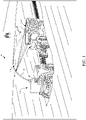
- FIG. 1 is a pictorial illustration showing one example of a self-propelled forage harvester 100 filling a tractor-pulled grain cart (or receiving vehicle) 102.
- Cart 102 thus defines an interior that forms a receiving vessel 103 for receiving harvested material through a receiving area 112.
- a tractor 104 that is pulling grain cart 102, is positioned directly behind forage harvester 100.
- forage harvester 100 has a camera 106 mounted on the spout 108 through which the harvested material 110 is traveling.
- the spout 108 can be pivotally or rotationally mounted to a frame 107 of harvester 100.
- Camera 106 can be a stereo-camera or a mono-camera that captures an image (e.g., a still image or video) of the receiving area 112 of cart 102.
- the receiving area 112 is defined by an upper edge of the walls of cart 102.
- the automatic fill control system can gauge the height of harvested material in cart 102, and the location of that material. The system thus automatically controls the position of spout 108 and flap 109 to direct the trajectory of material 110 into the receiving area 112 of cart 102 to obtain an even fill throughout the entire length and width of cart 102, while not overfilling cart 102.
- automatically it is meant, for example, that the operation is performed without further human involvement except, perhaps, to initiate or authorize the operation.
- FIG. 2 is a pictorial illustration showing another example of a self-propelled forage harvester 100, this time loading a semi-trailer (or receiving vessel on a receiving vehicle) 122 in a configuration in which a semi-tractor is pulling semi-trailer 122 alongside forage harvester 100. Therefore, the spout 108 and flap 109 are positioned to unload the harvested material 110 to fill trailer 122 according to a pre-defined side-by-side fill strategy.
- FIG. 2 shows that camera 106 can capture an image (which can include a still image or video) of semi-trailer 122. In the example illustrated in FIG. 2 , the field of view of camera 106 is directed toward the receiving area 120 of trailer 122 so that image processing can be performed to identify a landing point for the harvested material in trailer 122.
- machine 100 is a combine harvester
- the spout 108 is not moved relative to the frame during normal unloading operations. Instead, the relative position of the receiving vehicle 102, 122 and the combine harvester is changed in order to fill the receiving vessel 103 as desired.
- the relative position of the receiving vessel, relative to the combine harvester is changed so that the spout is first filling the receiving vessel at the front end, and then gradually fills the receiving vessel moving rearward.
- the combine harvester and towing vehicle may have machine synchronization systems which communicate with one another.
- the machine synchronization system on the combine harvester can send a message to the machine synchronization system on the towing vehicle to nudge the towing vehicle slightly forward or rearward relative to the combine harvester, as desired.
- the machine synchronization system on the combine harvester may receive a signal from the fill control system on the combine harvester indicating that the position in the receiving vessel that is currently being filled is approaching its desired fill level. In that case, the machine synchronization system on the combine harvester can send a "nudge" signal to the machine synchronization system on the towing vehicle.
- the nudge once received by the machine synchronization system on the towing vehicle, causes the towing vehicle to momentarily speed up or slow down, thus nudging the position of the receiving vessel forward or rearward, respectively, relative to the combine harvester.
- FIG. 3 is a pictorial illustrating showing one example of an operator interface display 124 that can be displayed on a display mechanism 126, for the operator in an operator compartment of forage harvester 100.
- the operator interface display 124 in FIG. 3 shows a view of images (or video) captured by camera 106 of material 110 entering trailer 122.
- An image processing system on harvester 100 illustratively identifies the perimeter of the opening 128 in trailer 122 and also processes the image of the material 110 in trailer 122 to determine the fill height relative to opening 128.
- the perimeter defining opening 128 can be visually enhanced by overlaying a visual overlay over the opening 128 so that the operator can easily identify the opening 128, as it is being recognized by the image processing system.
- a fill control system allows the operator to use a touch gesture (or other command input, such as a point and click input) selecting the area of trailer 122 on display 124 that corresponds to the void 130.
- the fill control system thus allows the operator to provide an input through interface 124, marking a location (such as the location of void 130) where material 110 is to be directed.
- the operator may simply touch the screen in the area of void 130.
- the touch gesture will be detected by the fill control system and the fill control system will automatically generate control signals to move spout 108 so that it is depositing material 110 in the area of void 130.
- Generating the control signals to reposition spout 108 can be done in different ways. For instance, once the operator touches or otherwise selects (such as with a point and click device) an area of display 124, the control system identifies the pixel or pixel sets that were selected (e.g., touched or otherwise selected) and, from those pixels, identifies a corresponding physical area or landing point within trailer 122. The control system can then calculate the position that spout 108 needs to be in in order to fill material 110 in that particular landing point in trailer 122.
- spout 108 keeps depositing material in the area of void 130 (or another location commanded by the operator input) until some criteria are met, at which point the fill control system moves spout 108 back to resume filling trailer 122 at the location it was at prior to moving to the area of void 130.
- the criteria for resuming the prior fill operation can be any of a variety of different criteria.
- the criteria may be timing criteria. For instance, when the user provides a reposition command to move spout 108 to begin filling in the area of void 130, the control system may move spout 108 to fill in that area for a predetermined amount of time (such as 10 seconds, etc.). After that time has elapsed, then the control system may move spout 108 to resume filling trailer 122 at the previous location.
- the criteria may be fill level or threshold criteria.
- spout 108 may be repositioned to fill the area of void 130 until the fill level in the area of void 130 reaches a threshold fill level.
- the threshold levels may be increased so that the trailer 122 in the area of void 130 can be filled with more material 110.
- forage harvester 100 may have an automatic fill control system (or active fill control system) which fills trailer 122 according to a fill strategy (such as a back-to-front fill strategy, front-to-back fill strategy, etc.).
- a current location indicator (such as indicator 132) may be displayed to show the current location where material 110 is being loaded into trailer 122 through spout 108 and the direction that spout 108 will be moving relative to trailer 122 as the filling operation continues. It can be seen in FIG. 3 , for instance, that indicator 132 is an arrow pointing in the front-to-back direction.
- the location of arrow 132 on the representation of trailer 122 indicates the current fill position, while the direction of the arrow indicates the direction that spout 108 will be moved relative to trailer 122 in executing the selected front-to-back fill strategy. Therefore, in one example, when the operator taps the display screen in, or otherwise selects, the area of trailer 122 corresponding to void 130, the indicator 132 remains in place to indicate the location to which spout 108 will return after it temporarily fills the area of trailer 122 corresponding to void 130.
- the operator interface display 124 can be generated.
- the operator may also select an active fill strategy using a touch gesture. For instance, at the beginning of a fill operation, or at any time during the fill operation, the operator may touch the representation of trailer 122 on display 124 and swipe in one direction or the other or provide another touch gesture.
- the system can detect that touch gesture and interpret it as selecting a back-to-front fill strategy. The control system then begins filling the trailer toward the rear of the trailer and continues to fill the trailer moving toward the front of the trailer.
- FIG. 4 is another example of an operator interface display 134 which can be generated for the operator of harvester 100. Some items are similar to those shown in FIG. 3 and they are similarly numbered.
- Display 134 is a representation of a top-down view of trailer 122. The top-down view is accompanied by a graph 136 that illustrates the fill level of the different portions of trailer 128.
- image processing can divide the area of the trailer 128 into bins or discrete volumes (some of which are illustrated by the dashed lines in FIG. 4).
- FIG. 4 shows that the bins 138, 140, 142, and 144 correspond to volumes defined by a cross section of the trailer 128.
- Each of the bins has a corresponding bar graph in graph 136, indicating the fill level of that bin in trailer 128.
- the bar graphs corresponding to bins 138 and 140 are at zero showing that there is no material 110 at those locations in trailer 128.
- the bar graphs corresponding to bins 142 and 144 show increasing levels of material 110 in those bins.
- the location of the bins may be displayed on display 134, or they may be hidden.
- the operator may see that the location of trailer 128 corresponding to bins 138 and 140 is empty.
- the operator may provide a reposition command input (such as tapping or touching the display 134 in the area of bin 138 or 140) to indicate that the operator desires to have the spout 108 repositioned to a location which fills the volume corresponding to the selected bin in trailer 122.
- a reposition command input such as tapping or touching the display 134 in the area of bin 138 or 140
- the control system automatically repositions the spout 108 from the position illustrated by indicator 132 to the position of bin 138, and begins filling at that position.
- the automatic fill strategy can be temporarily suspended, and trailer 122 may be filled in the location of bin 138 until some resume criteria are met, at which point the spout 108 is controlled to resume filling at the location of indicator 132, and the selected fill strategy is re-activated.
- the harvester 100 may continue to fill the area of trailer 122 corresponding to bin 138 until the operator enters another command (such as by tapping an area of display 124 corresponding to another bin), or tapping indicator 132.
- the control system translates that pixel location into a physical bin location on trailer 122 and moves the spout 108 so that it begins filling the trailer at that bin location.
- the operator may use a touch gesture (such as a touch and swipe touch gesture) to indicate a desired active fill strategy.
- the control system can interpret the touch gesture to identify the fill strategy and begin implementing that fill strategy.
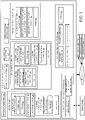
- FIG. 5 is a block diagram showing one example of a mobile work machine which comprises agricultural harvester 100, in more detail.
- Agricultural harvester 100 includes one or more processors or servers 148, communication system 150, data store 152, sensors 154, fill control system 156, void fill control system 158, operator interface mechanisms 160, controllable subsystems 162, and other harvester functionality 164.
- Sensors 154 can include automatic fill control sensors 164 that are used by fill control system 156.
- Sensors 164 can include camera 106 (which may be a mono-camera, stereo-camera or another type of camera) and other sensors 166.
- the other sensors can include such things as Doppler sensors, RADAR sensors, other image sensors or any of a wide variety of other types of sensors.
- Sensors 154 can also include spout position sensor 168 and flap position sensor 170.
- Spout position sensor 168 illustratively senses the position of spout 108 relative to the frame of harvester 100. Sensor 168 can do this by sensing the position of an actuator that drives movement of spout 108 relative to the frame of harvester 100, or sensor 168 can be a rotary position sensor, a linear sensor, a potentiometer, a Hall Effect sensor, or any other of a wide variety of sensors that can sense the position of spout 108 relative to the frame of harvester 100.
- flap position sensor 170 can be a sensor that senses the position of the flap 109.
- sensor 170 can be a rotary position sensor, a linear sensor, a potentiometer, a Hall Effect sensor, a sensor that senses a position of an actuator that drives movement of flap 109, or any of a wide variety of other sensors.
- Sensors 154 can also include machine synchronization sensors 172.
- Sensors 172 can include relative position sensors 174 that sense the relative position of the harvester, relative to the receiving vehicle. Such sensors can include RADAR sensors, Doppler sensors, image or other optical sensors, or a wide variety of other relative position sensors.
- the relative position sensors 174 can also include position sensors (such as a GPS receiver, or another GNSS sensor) that senses the position of harvester 100. This can be used, in conjunction with another position sensor on the receiving vehicle, to determine the position of the two vehicles relative to one another.
- the machine synchronization sensors 172 can include other sensors 176, and sensors 154 can include a wide variety of other sensors 178 as well.
- Fill control system 156 illustratively controls operations of various parts of harvester 100 (and possibly the towing vehicle 104) to fill the receiving vehicle 102, 122, as desired.
- Fill control system 156 can include automatic fill control system 180 (which, itself, can include fill strategy selector 182, fill strategy implementation processor 184 and other items 186), manual fill control system 188 (which, itself can include manual set point detector 190 and other items 192), and/or machine synchronization fill control system 194.
- Fill control system 156 can also include fill control signal generator 196 and other items 198.
- Void fill control system 158 can include operator interface display generator 200, operator interaction detection and processing system 202, position control signal generator 204 and other items 206.
- Operator interface mechanisms 160 can include interactive display mechanism 126 and a variety of other operator interface mechanisms 208.
- Controllable subsystems 162 can include propulsion subsystem 210, steering subsystem 212, one or more spout actuators 214, one or more flap actuators 216 and other items 218.
- FIG. 5 also shows that operator 220 can interact through operator interface mechanism 160 to control and manipulate agricultural harvester 100.
- harvester 122 is connected over network 222 to receiving vehicle 102, 122, towing vehicle 104 and/or it can be connected to other systems 224.
- Communication system 150 can facilitate communication among the items of harvester 100 and with other items over network 222.
- Network 222 can be a wide area network, a local area network, a near field communication network, a cellular communication network, or any of a variety of other networks or combinations of networks. Therefore, communication system 150 can use a controller area network (CAN) bus or other controllers to facilitate communication of the items on harvester 100 with other items.
- CAN controller area network
- Communication on system 150 can also be different kinds of communication systems, depending on the particular network or networks 222 over which communication is to be made.
- Operator interface mechanisms 160 can be a wide variety of different types of mechanisms.
- Interactive display mechanism 126 can be a display mechanism, such as that shown in FIGS. 3 and 4 , or mechanism 126 can be a display mechanism on a mobile device, such as a tablet computer, a smartphone, etc., that is carried by the operator 200 and/or mounted in the operator compartment of harvester 100.
- interactive display mechanism 126 can be a touch sensitive display mechanism, a display mechanism that receives inputs through a point and click device, or other kinds of display mechanisms.
- Operator interface mechanisms 208 can include a steering wheel, levers, buttons, pedals, a microphone and speaker (where speech recognition and speech synthesis are provided), joysticks, or other mechanical, audio, visual or haptic mechanisms that can be used to provide outputs to operator 220 or to receive inputs from operator 220.
- Controllable subsystems 162 can be controlled by various different items on harvester 100.
- Propulsion subsystem 210 can be an engine that drives ground-engaging elements (such as wheels or tracks) through a transmission, hydraulic motors that are used to drive ground-engaging elements, electric motors, direct drive motors, or other propulsion systems that are used to drive ground-engaging elements to propel harvester 100 in the forward and rearward directions.
- Propulsion subsystem 110 can illustratively be controlled with a throttle to increase or decrease the speed of travel of harvester 100.
- Steering subsystem 212 can be used to control the heading of harvester 100.
- One or more spout actuators 214 are illustratively configured to drive rotation or movement of spout 108 relative to the frame of harvester 100.
- Actuators 214 can be hydraulic actuators, electric actuators, pneumatic actuators, or any of a wide variety of other actuators.
- one or more flap actuators 216 are used to drive the position of flap 109 relative to spout 108.
- the flap actuators 216 can also be hydraulic actuators, electric actuators, pneumatic actuators, or any of a wide variety of other actuators.
- Fill control system 156 can use automatic fill control system 180 to perform automated fill control to automatically execute a fill strategy in filling one of the receiving vehicles 102, 122. Therefore, fill strategy selector 182 can detect a user input selecting a fill strategy, or another input selecting a fill strategy and access data store 152 for a stored fill algorithm that can be executed to perform the selected fill strategy. For instance, where the selected fill strategy is a back-to-front strategy, the algorithm will direct filling of the receiving vehicle beginning at the back of the receiving vehicle and moving to the front of the receiving vehicle. Other fill strategies can be selected as well.
- Fill strategy implementation processor 184 receives inputs from the automatic fill control sensors 164, spout position sensor 168 and flap position sensor 170 and generates an output to fill control signal generator 196 based upon the inputs from the sensors, to execute the desired automatic fill control strategy.
- Fill control signal generator 196 can generate control signals to control any of the controllable subsystems 262 (or other items) to execute the fill strategy being implemented by fill strategy implementation processor 184.
- Manual fill control system 188 can use manual set point detector 190 to detect a manual input from operator 220 (e.g., through interactive display mechanism 126) to identify a landing point in the receiving vehicle 102, 122 where the operator 220 desires the filling operation to be performed. Manual fill control system 188 can then generate outputs to fill control signal generator 196 which generates control signals to control the controllable subsystems 162 so that filling commences at the manually identified landing point in the receiving vehicle 102, 122.
- Machine synchronization fill control system 194 can receive operator inputs or other inputs, as well as sensor inputs from sensors 154 to generate outputs to fill control signal generator 196 in order to synchronize the positions of agricultural harvester 100 and receiving vehicle 102, 122 so that a desired filling operation is performed. For instance, machine synchronization control system 194 can receive sensor inputs identifying that the current position that is being filled in receiving vehicle 102, 122, is at a desired fill level so that the receiving vehicle should move forward or rearward relative to agricultural harvester 100. Machine synchronization fill control system 194 then generates an output to fill control signal generator 196 indicating this.
- Fill control signal generator 196 can generate an output either to controllable subsystems 162, or communication system 150, or both, based on the inputs from machine synchronization fill control system 194. For instance, where the output from system 194 indicates that the receiving vehicle 102, 122 should move forward relative to agricultural harvester 100, then fill control signal generator 196 can control communication system 150 to communicate with a corresponding machine synchronization fill control system 194 on towing vehicle 104 indicating that towing vehicle 104 should "nudge" forward relative to the harvester 100 by momentarily increasing its ground speed and then returning to its current ground speed.
- fill control signal generator 196 can generate control signals to control the propulsion subsystem 210 on agricultural harvester 100 to momentarily change the speed of agricultural harvester 100 so that the position of the receiving vehicle 102, 122 relative to agricultural harvester 100 changes as desired.
- Void fill control system 158 can use operator interface display generator 200 to generate an operator interface display indicative of the receiving vessel 102, 122 and the amount of material in the receiving vessel 102, 122.
- the operator interface display may be similar to one of the displays shown in FIGS. 3 and 4 or different.
- Operator interaction detection and processing system 202 can detect operator inputs through the interface display that was generated by generator 200 and displayed on interactive display mechanism 126.
- the operator input may be a reposition command input that illustratively identifies a selected landing point in receiving vehicle 102, 122 to which the operator wishes to reposition the filling operation, at least temporarily.
- Operator interaction detection and processing system 202 then translates the landing point selected by operator 220 on interactive display mechanism 126 to a landing point in receiving vehicle 102, 122 that is to be filled. Processing system 202 identifies the actions needed to be taken in order to begin filling at that landing point.
- system 202 can identify the spout and flap angles that are needed in order to commence filling at the selected landing point in receiving vehicle 102, 122.
- System 202 can output those angles to position control signal generator 204 which can then generate control signals to control spout actuators 214 and flap actuators 216 to commence the fill operation at the selected location.
- system 202 can provide an output to fill control system 156 temporarily suspending fill control system 156 from controlling the fill operation. For instance, if the automatic fill control system 180 is executing an automatic fill strategy, then the signal from system 202 can temporarily suspend system 180 from executing that fill strategy until criteria are met at which point system 180 can resume that fill strategy.
- the signal from system 180 can temporarily suspend system 188 from maintaining the fill operation at that previously selected landing point, and allow position control signal generator 204 to reposition the spout and flap to commence filling at the newly selected landing point.
- the signal from system 202 can cause system 194 to generate output signals to move the filling operation to the operator-selected landing point in receiving vehicle 102, 122, until criteria are met.
- the signal from system 202 can cause machine synchronization fill control system 194 to suspend its control operation and allow position control signal generator 204 to control the propulsion subsystem 210 and/or steering subsystem 212 to change the relative position of harvester 100 and receiving vehicle 102, 122 (to reposition the spout relative to the receiving vehicle based on the reposition command input) so that the filling operation commences at the operator-selected landing point.
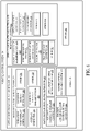
- FIG. 6 is a flow diagram illustrating one example of void fill control system 158, in more detail. Some of the items in FIG. 6 are similar to those shown in FIG. 5 , and they are similarly numbered. However, FIG. 6 shows one example of operator interface display generator 200, operator interaction detection and processing system 202, and reposition control signal generator 204, in more detail. Before describing the operation of void fill control system 158 in more detail, some of the items in system 158, and their operation, will first be provided. Operator interface display generator 200 illustratively includes receiving vehicle display system 250 (which, itself, can include streaming video display generator 252, top-down display generator 254, and other items 256), overlay generator 258, current fill location marker system 260, and other items 262.
- vehicle display system 250 which, itself, can include streaming video display generator 252, top-down display generator 254, and other items 256
- overlay generator 258 current fill location marker system 260, and other items 262.
- Operator interaction detection and processing system 202 can include vessel bin/location assignment system 264, operator input detector 266 (which, itself, can include point and click detector 268, touch gesture detector 270, and other items 272), input processing system 274 (which, itself, can include set point location identifier 276, resume detector 278, fill strategy identifier 280, and other items 282), and other items 284.
- Reposition control signal generator 284 can include automatic fill control suspension signal controller 286, spout/flap control signal generator 288, machine synchronization control signal generator 290, resume criteria evaluation system 292, and other items 294.
- Receiving vessel display system 250 generates an operator display that represents the receiving vessel, and a fill level of material that the harvester is transferring to the receiving vessel.
- Streaming video display generator 252 generates a streaming video display based on video information captured by camera 106.
- Top-down display generator 254 can generate a top-down representation of the receiving vessel 103, such as that shown in FIG. 4 .
- the top-down display can be a pictorial illustration or it can be generated in other ways.
- top-down display generator 254 can generate the fill level display portion 136, or another display portion that shows the fill level of material 110 in the receiving vessel.
- Overlay generator 258 can generate one or more different types of overlays. For instance, overlay generator 258 can generate an overlay that visually distinguishes the perimeter of the receiving vessel 103, or the opening 128 of the receiving vessel 103 so that the opening can be quickly identified, visually, by the operator. Overlay generator 258 can also generate other overlay display elements, such as the bin display elements shown as dashed lines in FIG. 4 (which can also be depicted in FIG. 3 ) and other overlays.
- Current fill location marker system 260 generates the current fill location (such as marker 132 shown in FIGS. 3 and 4 ) that indicates the current fill position, or the landing point where spout 108 is currently depositing material into the receiving vessel 103.
- the current fill location marker can be an arrow or other directional marker that identifies the direction which spout 108 is moving relative to the receiving vessel 103, during the filling operation.
- Operator interaction detection and processing system 202 detects information indicative of operator interactions with the operator interface display, and processes those interactions.
- Vessel bin/location assignment system 264 first performs image processing on the captured images to identify the receiving vessel 103 in the captured images. It then divides the receiving vessel 103 into a number of discrete bins or locations which correspond to consecutive volumes in the receiving vessel 103. For instance, system 264 can analyze the image or representation shown in FIG. 4 and divide that image or representation into different bins, some of which are shown as bins 138-144 in FIG. 4 . The same can be done with respect to the image illustrated in FIG. 3 .
- Operator input detector 266 then detects any operator inputs or interactions with the operator interface display.
- Point and click detector 268 can detect a point and click input on the operator interface display.
- Touch gesture detector 270 detects touch gestures on the operator interface display.
- Input processing system 274 processes the detected operator inputs to identify an operator intent or an operator command corresponding to the detected input.
- Set point location identifier 276 can receive an indication of the detected operator input from operator input detector 266 and determine that the operator input is identifying a reposition command.
- the reposition command identifies a set point position (or landing point) indicating that the operator wishes the spout to be repositioned to commence filling at the commanded landing point in the receiving vessel 103. For instance, assume that the operator taps on a pixel within the displayed representation of bin 138 in FIG. 4 . In that case, set point location identifier 276 can access a correlation between the pixel where the tap was detected and the bin 138. Set point location identifier 276 can then generate an output indicating that the user has commanded the filling operation to reposition the spout 108 so that it commences filling bin 138 in receiving vessel 103.
- Resume detector 178 can detect criteria indicating that the fill control system should resume controlling the fill operation as it was doing prior to the detected operator reposition command. For instance, continuing with the example discussed above, assume that the operator has tapped on a location corresponding to bin 138 in FIG. 4 . Again, assume that the void fill control system 158 or fill control system 156 has, in response, repositioned the spout 108 so it commences filling bin 138. At some point, the fill control system 156 detects that the material 110 has reached a desired fill level in bin 138. This can be done by analyzing the captured image to identify the fill level of material 110 in bin 138.
- resume detector 278 which detects that the resume criteria have been met so that filling automatically resumes at its prior landing point (prior to receiving the user reposition command) and the control signals are generated to move the spout 108 so that filling resumes at that previous landing point.
- resume detector 278 may detect other resume criteria. For instance, it may be that the operator again taps on location indicator 132. This will be detected by touch gesture detector 270 and an indication of this will be provided to resume detector 278.
- Resume detector 278 may interpret this input command as a command by the operator to resume filling at the prior landing point (the landing point prior to receiving the reposition command). Other resume criteria may be detected by resume detector 278 as well.
- operator 220 may select the fill strategy using a touch gesture on the operator interface display. For instance, when a filling operation is about to commence, the operator may touch and swipe on the depiction of the receiving vessel, depicted on the operator interface display. The location of the touch, and the direction of the swipe, may be used by fill strategy identifier 280 to identify a fill strategy that is to be employed during the filling operation. For instance, if the operator touches the back portion of the receiving vessel and swipes in a forward direction, then this may be interpreted by fill strategy identifier 280 as identifying a back-to-front fill strategy. Thus, fill strategy identifier 280 may output an indication of this to fill strategy selector 182 in fill control system 256 so that fill strategy selector 182 selects the back-to-front fill strategy.
- a touch gesture For instance, when a filling operation is about to commence, the operator may touch and swipe on the depiction of the receiving vessel, depicted on the operator interface display. The location of the touch, and the direction of the swipe
- the outputs from operation interaction and processing system 202 can be provided to reposition control signal generator 204 which provides output signals to either fill control signal generator 196 or directly to controllable subsystems 162, or both, to implement control for repositioning spout 108 based upon the operator reposition command, and to again resume filling at the prior landing point once resume criteria are detected.
- automatic fill control system 180 is implementing an automatic fill strategy (or an active fill strategy) when the operator reposition command is detected.
- automatic fill control suspension controller 286 temporarily suspends the automatic fill control strategy so that the spout 108 can be repositioned based on the operator reposition command.
- Automatic fill control suspension controller 286 enables the automatic fill control strategy again, once the resume criteria are detected.
- Spout/flap control signal generator 288 generates control signals to control the spout actuators 214 and flap actuators 216.
- generator 288 can calculate the spout and flap angles needed to reposition spout 108 to the commanded landing point and to resume at its prior landing point, and provide those angles to fill control signal generator 196 which, in turn, controls the spout and flap actuators 214 and 216, respectively, to move to the commanded angles.
- spout/flap control signal generator 288 can directly provide control signals to actuate spout actuators 214 and flap actuators 216.
- machine synchronization control signal generator 290 In an example in which agricultural harvester 100 has machine synchronization fill control system 194, machine synchronization control signal generator 290 generates control signals and provides them to machine synchronization fill control system 194 to reposition the spout 108 relative to the receiving vehicle, based upon the operator reposition command, and to again position spout 108 relative to the receiving vehicle to resume filling at the prior landing point when the resume criteria are met.
- machine synchronization control signal generator 298 provides control signals to machine synchronization fill control system 194 to reposition spout 108, relative to the receiving vehicle, to commence filling at the landing point indicated by the reposition command.
- machine synchronization control signal generator 290 provides control signals to machine synchronization fill control system 194 to move the position of spout 108, relative to the receiving vehicle, back to the position it was in prior to receiving the reposition command.
- Resume criteria evaluation system 292 can evaluate the resume criteria detected by resume detector 278 to determine if and when to resume filling at the prior landing point in the receiving vehicle. For instance, if resume detector 278 detects that the fill level is within 10% of a threshold value, then resume criteria evaluation system 292 may determine when and how quickly to move spout 108 to the prior landing point and resume filling according to a prior active fill strategy. This is just one example of how resume criteria evaluation system 292 can evaluate the resume criteria to resume a prior filling operation.
- FIGS. 7A and 7B (collectively referred to herein as FIG. 7 ) show a flow diagram illustrating one example of the operation of agricultural harvester 100 in beginning a fill operation, detecting an operator reposition input, repositioning the location of spout 108 relative to the receiving vehicle based upon the operator reposition input, detecting resume criteria, and resuming the prior fill operation. It is first assumed that harvester 100 is beginning a harvesting operation, or that the harvester is operating, as indicated by block 300 in the flow diagram of FIG. 7 . As discussed above, agricultural harvester 100 may be a self-propelled forage harvester 302, a combine harvester 304, a sugarcane harvester 306 or another harvester 308.
- Camera 106 can capture images (such as video or other images) of the receiving vessel and vessel bin/location assignment system 264 processes those images and identifies discrete locations or bins in the receiving vessel. Identifying bins or defining discrete locations within the receiving vessel is indicated by block 310. As discussed above, system 264 can divide the receiving vessel into bins by processing images captured by camera 106, as indicated by block 312. In another example, system 264 can identify a type of receiving vessel (such as a type of wagon) and then access the dimensions of that receiving vessel from memory or from other predetermined data. System 264 can then divide the receiving vessel into a desired number of bins based on the dimensions.
- a type of receiving vessel such as a type of wagon
- each vessel type is already assigned a number and configuration of different bins so that all system 264 needs to do is identify the type of receiving vessel or receiving vehicle and then access the known bin configuration for that receiving vessel. Recognizing the receiving vessel to identify and assign bins is indicated by block 314. Dividing the receiving vessel into a number of discrete locations or bins can be done in other ways as well, as indicated by block 316.
- Operator interface display generator 200 displays a representation of the receiving vehicle on an interactive display device 126. Displaying the representation of the receiving vehicle is indicated by block 318 in the flow diagram of FIG. 7 .
- the representation can be displayed on a touch sensitive display device as indicated by block 320.
- the representation can be a streaming video with the vessel opening and the bins overlaid on top of the images, as indicated by block 332.
- the representation is a top-down graphical or pictorial representation of the vessel and it may also have the bins displayed thereon, as indicated by block 334.
- the representation of the receiving vessel can be displayed on an interactive display in other ways as well, as indicated by block 336.
- Operator interaction detection and processing system 202 then detects an operator reposition command input on the interactive display, as indication be block 338.
- the operator reposition command can be a touch input 340, a point and click input 342, or another type of input 344 on the representation of the receiving vessel on the interactive display.
- Input processing system 274 then identifies a location where the spout 108 is to be repositioned based upon the pixel location on the interactive display that received the reposition command from the operator. Identifying a location where the spout 108 is to be repositioned based upon the reposition command input is indicated by block 346 in the flow diagram of FIG. 7 . This can be done in a variety of different ways. For instance, set point location identifier 276 can access a pre-defined pixel-to-bin correlation which correlates the assigned bins in the receiving vessel to the different pixel locations on the image. Then, by identifying the particular pixel or set of pixels that receive the reposition command input from the operator, the correlation outputs the corresponding bin in the receiving vessel.
- Accessing a pre-defined pixel-to-bin correlation is indicated by block 348 in the flow diagram of FIG. 7 .
- set point location identifier 276 makes a runtime correlation.
- the location of the receiving vessel within the image being processed may change over time. Therefore, the correlation between a particular pixel on the display device and a bin assigned to the receiving vessel may also change over time.
- a real-time (or near real time) correlation between the pixels on the displayed representation of the receiving vessel and the bins in the receiving vessel is generated and that real-time correlation is used to identify the location within the receiving vessel that the user has commanded with the reposition command.
- Using a runtime correlation to identify where to reposition the spout 108, relative to the receiving vessel 103, based upon the reposition command is indicated by block 350 in the flow diagram of FIG. 7 .
- Set point location identifier 276 can identify a landing point where the spout 108 is to be repositioned based upon the pixel location that received the reposition command in other ways as well, as indicated by block 352.
- Set point location identifier 276 then outputs the identified set point location (or commanded landing point) to reposition control signal generator 204, as indicated by block 354 in the flow diagram of FIG. 7 .
- Signal generator 204 generates output signals to control the position of the spout 108 relative to the receiving vessel 103 to begin filling at the identified landing point location, as indicated by block 356 in the flow diagram of FIG. 7 .
- an automatic fill strategy is being used, it is temporarily suspended by automatic fill control suspension controller 286. Temporarily suspending an automatic fill strategy is indicated by block 358 in the flow diagram of FIG. 7 .
- Spout/flap control signal generator 288 can generate control signals to control the spout and flap actuators based upon the set point location (or landing point) in the reposition command, as indicated by block 360.
- machine synchronization control signal generator 290 can generate outputs to system 194 to reposition the spout relative to the receiving vessel 103, as indicated by block 362.
- Signal generator 204 can generate control signals to control the position of the spout (and/or flap) relative to the receiving vessel 103 to begin filling at the identified landing point in other ways as well, as indicated by block 364.
- Void fill control system 158 and/or fill control system 156 then perform the fill operation at the identified landing point (e.g., in the identified bin) in the receiving vessel 103 until resume criteria are met, as indicated by block 366 in the flow diagram of FIG. 7 .
- the resume criteria may be the elapse of a predetermined time period (such as 10 seconds) as indicated by block 368.
- the resume criteria may be fill level criteria which are used to identify when sufficient material 110 has been filled at the landing point, as indicated by block 370.
- the fill level may be identified using threshold values, fill level ranges, or other criteria.
- the resume criteria may include receiving a "resume input" from the operator, through the interactive display, as indicated by block 372.
- the resume criteria may be other criteria 374 as well.
- resume detector 278 detects the resume criteria and provides them to resume criteria evaluation system 292.
- Resume criteria evaluation system 292 determines that the resume criteria have been met. Determining whether the resume criteria have been met is indicated by block 376 in the flow diagram of FIG. 7 .
- the output from system 292 is then used by fill control system 156 to resume the prior filling operation, as indicated by block 378.
- Fill control system 156 then takes over operation and changes the position of spout 108 relative to the receiving vessel 103 to resume filling at the prior landing point, prior to repositioning the spout 108. Adjusting the position of spout 103 relative to receiving vessel 103 to perform the filling operation at the prior landing point is indicated by block 380.
- automatic fill control suspension controller 286 re-engages that automatic fill control system 180 so that it can resume where it left off. Re-engaging the automatic fill control system 180 and continuing with the prior automatic fill strategy is indicated by block 382 in the flow diagram of FIG. 7 . Resuming the prior filling operation can be done in other ways as well, as indicated by block 384. Processing then reverts to block 318 where the system continues to display a representation of the receiving vessel 103 on an interactive display mechanism, and waits for another operator reposition command. Continuing this operation until the harvesting operation is complete is indicated by block 386 in the flow diagram of FIG. 7 .
- FIG. 8 is a flow diagram illustrating one example of the operation of agricultural harvester 100 in receiving a touch gesture and selecting an automatic fill strategy based upon that touch gesture.
- Operator interface display generator 200 displays a representation of the receiving vehicle or receiving vessel on an interactive display mechanism, as indicated by block 388 in the flow diagram of FIG. 8 .
- Touch gesture detector 270 detects a touch gesture on the representation of the receiving vessel, as indicated by block 389.
- the touch gesture may be a swipe gesture 390, a tap or touch and swipe gesture 392, a sequence of taps 394, or another touch gesture 396.
- Fill strategy identifier 280 then detects the touch gesture as an automatic fill strategy selection input and provides an indication of that input to fill strategy selector 182. Identifying an automatic fill strategy based upon the detected touch gesture is indicated by block 398 in the flow diagram of FIG. 8 .
- the fill strategy can be any of a wide variety of different fill strategies such as a front-to-back strategy 400, a back-to-front strategy 402, or another strategy 404.
- Providing the identified automatic fill strategy to the fill strategy selector in automatic fill control system 180 is indicated by block 406 in the flow diagram of FIG. 8 .
- Fill strategy selector 182 selects the fill strategy (e.g., loads the fill strategy algorithm for implementing that strategy), from data store 152, or in another way.
- Fill strategy implementation processor 184 then generates outputs to control signal generator 196 to control the filling operation by implementing the selected fill strategy, as indicated by block 408.
- the filling operation that takes place at the repositioned landing point can be performed by suspending an automatic fill strategy that is currently being implemented and repositioning the filling operation, or by changing a manually set landing point based upon the reposition command.
- the filling operation can take place at the repositioned location temporarily, until resume criteria are met, at which point control can revert to performing the previous filling operation, at the previous landing point in the receiving vessel.
- processors and servers include computer processors with associated memory and timing circuitry, not separately shown. They are functional parts of the systems or devices to which they belong and are activated by, and facilitate the functionality of the other components or items in those systems.
- the interface displays can take a wide variety of different forms and can have a wide variety of different user actuatable input mechanisms disposed thereon.
- the user actuatable input mechanisms can be text boxes, check boxes, icons, links, drop-down menus, search boxes, etc.
- the mechanisms can also be actuated in a wide variety of different ways.
- the mechanisms can be actuated using a point and click device (such as a track ball or mouse).
- the mechanisms can be actuated using hardware buttons, switches, a joystick or keyboard, thumb switches or thumb pads, etc.
- the mechanisms can also be actuated using a virtual keyboard or other virtual actuators.
- the screen on which they are displayed is a touch sensitive screen
- the mechanisms can be actuated using touch gestures.
- the device that displays them has speech recognition components, the mechanisms can be actuated using speech commands.
- data stores can each be broken into multiple data stores. All can be local to the systems accessing them, all can be remote, or some can be local while others are remote. All of these configurations are contemplated herein.
- the figures show a number of blocks with functionality ascribed to each block. It will be noted that fewer blocks can be used so the functionality is performed by fewer components. Also, more blocks can be used with the functionality distributed among more components..
Landscapes
- Engineering & Computer Science (AREA)
- Mechanical Engineering (AREA)
- Chemical & Material Sciences (AREA)
- Combustion & Propulsion (AREA)
- Transportation (AREA)
- Life Sciences & Earth Sciences (AREA)
- Environmental Sciences (AREA)
- Aviation & Aerospace Engineering (AREA)
- Guiding Agricultural Machines (AREA)
- Harvester Elements (AREA)
- Combines (AREA)
Abstract
Description
- The present description relates to mobile work machines. More specifically, the present description relates to implementing operator commanded placement of filling mechanisms when filling a receiving vehicle.
- There are a wide variety of different types of mobile work machine such as agricultural vehicles and construction vehicles. Some vehicles include harvesters, such as forage harvesters, sugar cane harvesters, combine harvesters, and other harvesters, that harvest grain or other crop. Such harvesters often unload into carts which may be pulled by tractors or semi-trailers as the harvesters are moving. Some construction vehicles include vehicles that remove asphalt or other similar materials. Such machines can include cold planers, asphalt mills, asphalt grinders, etc. Such construction vehicles often unload material into a receiving vehicle, such as a dump truck or other vehicle with a receiving vessel.
- As one example, while harvesting in a field using a forage harvester, an operator attempts to control the forage harvester to maintain harvesting efficiency, during many different types of conditions. The soil conditions, crop conditions, and other things can all change. This may result in the operator changing control settings. This means that the operator needs to devote a relatively large amount of attention to controlling the forage harvester.
- At the same time, a semi-truck or tractor-pulled cart is often in position relative to the forage harvester (e.g., behind the forage harvester or alongside the forage harvester) so that the forage harvester can fill the truck or cart while moving through the field. In some current systems, this requires the operator of the forage harvester to control the position of the unloading spout and flap so that the truck or cart is filled evenly, but not overfilled. Even a momentary misalignment between the spout and the truck or cart may result in hundreds of pounds of harvested material being dumped on the ground, or elsewhere, rather than in the truck or cart.
- Other harvesters such as combine harvesters and sugar cane harvesters, can have similar difficulties. Also, construction vehicles can be difficult to operate while attempting to maintain alignment with a receiving vehicle.
- Reference is made to the prior art of
EP 2 798 939 A1 . - An agricultural harvester has a frame and a spout that is mounted to the frame. A display shows a representation of harvested crop in a receiving vessel. A control system detects an operator input selecting a portion of the representation of the receiving vessel and automatically controls a fill control system to begin filling the receiving vessel, at the selected portion of the receiving vessel, with harvested material.
-
-
FIG. 1 is a pictorial illustration of one example of a work machine which comprises a forage harvester filling a receiving vehicle, with the receiving vehicle in a position behind the forage harvester. -
FIG. 2 is a pictorial illustration of one example of a work machine which comprises a forage harvester filling a receiving vehicle that is alongside the forage harvester. -
FIG. 3 is a pictorial illustration of an operator display showing video of a filling operation. -
FIG. 4 is a pictorial illustration of an operator display showing a top down representation of a receiving vessel and a graphical illustration of a fill level in the receiving vessel. -
FIG. 5 is a block diagram of one example of a harvester. -
FIG. 6 is a block diagram of one example of a void fill control system. -
FIGS. 7A and7B (collectively referred to herein asFIG. 7 ) show a flow diagram illustrating one example of detecting an operator input and performing control of a fill operation to fill a receiving vehicle. -
FIG. 8 shows a flow diagram illustrating one example of the operation of detecting an operator touch input and implementing a fill strategy in controlling a filling mechanism, based on the operator touch input. - The present discussion proceeds with respect to an agricultural harvester, but it will be appreciated that the present discussion is also applicable to construction machines as well, such as those discussed elsewhere herein. As discussed above, it can be very difficult for an operator to maintain high efficiency in controlling a harvester, and also to optimally monitor the position of the receiving vehicle. This difficulty can even be exacerbated when the receiving vehicle is located behind the forage harvester, so that the forage harvester is executing a rear unloading operation, but the difficulty also exists in side-by-side unloading scenarios.
- In order to address these issues, some automatic cart filling control systems have been developed to automate portions of the filling process. One such automatic fill control system uses a stereo camera on the spout of the harvester to capture an image of the receiving vehicle. An image processing system determines dimensions of the receiving vehicle and the distribution of the crop deposited inside the receiving vehicle. The system also detects crop height within the receiving vehicle, in order to automatically aim the spout toward empty spots and control the flap position to achieve a more even fill, while reducing spillage. Such systems can fill the receiving vehicle according to a fill strategy (such as front-to-back, back-to-front, etc.) that is set by the operator or that is set in other ways.
- However, there may be reasons that an operator wishes to at least temporarily deviate from the fill strategy. For instance, if the operator notices a void in the receiving vehicle that is not as full as the operator wishes, the operator may wish to temporarily switch filling to the location of the void to fill it to a higher fill level. Similarly, if the operator sees a certain type of terrain ahead, the operator may wish to increase the load at a particular location in the receiving vehicle to increase traction or stability over the terrain. To do this, the operator currently needs to disable the automatic fill control system, manually reset spout and flap angles, wait until the spout and flap are repositioned, adjust the position if necessary, wait until the desired fill operation is complete (e.g., the void is filled) and then reengage the automatic fill control system. This can be very cumbersome, especially while trying to simultaneously control the harvester.
- The present description thus proceeds with respect to a mobile work machine that detects and displays, on an operator display, a current location where material is being loaded in a receiving vessel. The present system detects an operator input command on the operator display, identifying a different location in the receiving vessel. A control system automatically controls the machine to switch to loading the material into the receiving vessel at the different location commanded by the operator input command. The present discussion also proceeds with respect to an example in which a user touch gesture can be used to quickly select an automatic fill strategy.
-
FIG. 1 is a pictorial illustration showing one example of a self-propelledforage harvester 100 filling a tractor-pulled grain cart (or receiving vehicle) 102.Cart 102 thus defines an interior that forms a receivingvessel 103 for receiving harvested material through areceiving area 112. In the example shown inFIG. 1 , atractor 104, that is pullinggrain cart 102, is positioned directly behindforage harvester 100. Also, in the example illustrated inFIG. 1 ,forage harvester 100 has acamera 106 mounted on thespout 108 through which the harvestedmaterial 110 is traveling. Thespout 108 can be pivotally or rotationally mounted to aframe 107 ofharvester 100. Camera 106 can be a stereo-camera or a mono-camera that captures an image (e.g., a still image or video) of thereceiving area 112 ofcart 102. In the example shown inFIG. 1 , thereceiving area 112 is defined by an upper edge of the walls ofcart 102. - When
harvester 100 has an automatic fill control system that includes image processing, as discussed above, the automatic fill control system can gauge the height of harvested material incart 102, and the location of that material. The system thus automatically controls the position ofspout 108 and flap 109 to direct the trajectory ofmaterial 110 into thereceiving area 112 ofcart 102 to obtain an even fill throughout the entire length and width ofcart 102, while not overfillingcart 102. By automatically, it is meant, for example, that the operation is performed without further human involvement except, perhaps, to initiate or authorize the operation. -
FIG. 2 is a pictorial illustration showing another example of a self-propelledforage harvester 100, this time loading a semi-trailer (or receiving vessel on a receiving vehicle) 122 in a configuration in which a semi-tractor is pullingsemi-trailer 122 alongsideforage harvester 100. Therefore, thespout 108 andflap 109 are positioned to unload the harvestedmaterial 110 to filltrailer 122 according to a pre-defined side-by-side fill strategy. Again,FIG. 2 shows thatcamera 106 can capture an image (which can include a still image or video) ofsemi-trailer 122. In the example illustrated inFIG. 2 , the field of view ofcamera 106 is directed toward the receivingarea 120 oftrailer 122 so that image processing can be performed to identify a landing point for the harvested material intrailer 122. - In other examples, where
machine 100 is a combine harvester, it may be that thespout 108 is not moved relative to the frame during normal unloading operations. Instead, the relative position of the receivingvehicle vessel 103 as desired. Thus, if a front-to-back fill strategy is to be employed, then the relative position of the receiving vessel, relative to the combine harvester, is changed so that the spout is first filling the receiving vessel at the front end, and then gradually fills the receiving vessel moving rearward. In such an example, the combine harvester and towing vehicle may have machine synchronization systems which communicate with one another. When the relative position of the two vehicles is to change, then the machine synchronization system on the combine harvester can send a message to the machine synchronization system on the towing vehicle to nudge the towing vehicle slightly forward or rearward relative to the combine harvester, as desired. By way of example, the machine synchronization system on the combine harvester may receive a signal from the fill control system on the combine harvester indicating that the position in the receiving vessel that is currently being filled is approaching its desired fill level. In that case, the machine synchronization system on the combine harvester can send a "nudge" signal to the machine synchronization system on the towing vehicle. The nudge, once received by the machine synchronization system on the towing vehicle, causes the towing vehicle to momentarily speed up or slow down, thus nudging the position of the receiving vessel forward or rearward, respectively, relative to the combine harvester. -
FIG. 3 is a pictorial illustrating showing one example of anoperator interface display 124 that can be displayed on adisplay mechanism 126, for the operator in an operator compartment offorage harvester 100. Theoperator interface display 124 inFIG. 3 shows a view of images (or video) captured bycamera 106 ofmaterial 110 enteringtrailer 122. An image processing system onharvester 100 illustratively identifies the perimeter of theopening 128 intrailer 122 and also processes the image of the material 110 intrailer 122 to determine the fill height relative toopening 128. Theperimeter defining opening 128 can be visually enhanced by overlaying a visual overlay over theopening 128 so that the operator can easily identify theopening 128, as it is being recognized by the image processing system. - In some cases the operator sees that, while the
material 110 is generally fillingtrailer 122 evenly, there may be voids in thetrailer 122, such as a void 130 at the forward end oftrailer 122. In that case, it may be that the operator wishes to fill void 130 with more material before continuing to fill the remainder oftrailer 122. Thus, as is discussed in greater detail below, a fill control system allows the operator to use a touch gesture (or other command input, such as a point and click input) selecting the area oftrailer 122 ondisplay 124 that corresponds to thevoid 130. The fill control system thus allows the operator to provide an input throughinterface 124, marking a location (such as the location of void 130) wherematerial 110 is to be directed. - For example, where the display screen on
mechanism 126 is a touch sensitive display screen, then the operator may simply touch the screen in the area ofvoid 130. The touch gesture will be detected by the fill control system and the fill control system will automatically generate control signals to movespout 108 so that it is depositingmaterial 110 in the area ofvoid 130. - Generating the control signals to reposition
spout 108 can be done in different ways. For instance, once the operator touches or otherwise selects (such as with a point and click device) an area ofdisplay 124, the control system identifies the pixel or pixel sets that were selected (e.g., touched or otherwise selected) and, from those pixels, identifies a corresponding physical area or landing point withintrailer 122. The control system can then calculate the position that spout 108 needs to be in in order to fillmaterial 110 in that particular landing point intrailer 122. - In one example, spout 108 keeps depositing material in the area of void 130 (or another location commanded by the operator input) until some criteria are met, at which point the fill control system moves spout 108 back to resume filling
trailer 122 at the location it was at prior to moving to the area ofvoid 130. - The criteria for resuming the prior fill operation can be any of a variety of different criteria. In one example, the criteria may be timing criteria. For instance, when the user provides a reposition command to move
spout 108 to begin filling in the area ofvoid 130, the control system may movespout 108 to fill in that area for a predetermined amount of time (such as 10 seconds, etc.). After that time has elapsed, then the control system may movespout 108 to resume fillingtrailer 122 at the previous location. In another example, the criteria may be fill level or threshold criteria. For instance, where the image processing system detects howfull trailer 122 is at different locations, then spout 108 may be repositioned to fill the area ofvoid 130 until the fill level in the area ofvoid 130 reaches a threshold fill level. In another example, where the fill level is already at the threshold level prior torepositioning spout 108, the threshold levels may be increased so that thetrailer 122 in the area ofvoid 130 can be filled withmore material 110. - It should also be noted that, in one example,
forage harvester 100 may have an automatic fill control system (or active fill control system) which fillstrailer 122 according to a fill strategy (such as a back-to-front fill strategy, front-to-back fill strategy, etc.). In that case, a current location indicator (such as indicator 132) may be displayed to show the current location wherematerial 110 is being loaded intotrailer 122 throughspout 108 and the direction that spout 108 will be moving relative totrailer 122 as the filling operation continues. It can be seen inFIG. 3 , for instance, thatindicator 132 is an arrow pointing in the front-to-back direction. The location ofarrow 132 on the representation oftrailer 122 indicates the current fill position, while the direction of the arrow indicates the direction that spout 108 will be moved relative totrailer 122 in executing the selected front-to-back fill strategy. Therefore, in one example, when the operator taps the display screen in, or otherwise selects, the area oftrailer 122 corresponding to void 130, theindicator 132 remains in place to indicate the location to whichspout 108 will return after it temporarily fills the area oftrailer 122 corresponding to void 130. These are just some examples of how theoperator interface display 124 can be generated. - In another example, as is discussed in greater detail elsewhere, the operator may also select an active fill strategy using a touch gesture. For instance, at the beginning of a fill operation, or at any time during the fill operation, the operator may touch the representation of
trailer 122 ondisplay 124 and swipe in one direction or the other or provide another touch gesture. By way of example, assume that the operator touches the rear portion oftrailer 122 and swipes forward toward the front portion oftrailer 122. In that case, the system can detect that touch gesture and interpret it as selecting a back-to-front fill strategy. The control system then begins filling the trailer toward the rear of the trailer and continues to fill the trailer moving toward the front of the trailer. -
FIG. 4 is another example of anoperator interface display 134 which can be generated for the operator ofharvester 100. Some items are similar to those shown inFIG. 3 and they are similarly numbered.Display 134 is a representation of a top-down view oftrailer 122. The top-down view is accompanied by agraph 136 that illustrates the fill level of the different portions oftrailer 128. By way of example, image processing can divide the area of thetrailer 128 into bins or discrete volumes (some of which are illustrated by the dashed lines inFIG. 4). FIG. 4 shows that thebins trailer 128. Each of the bins has a corresponding bar graph ingraph 136, indicating the fill level of that bin intrailer 128. The bar graphs corresponding tobins trailer 128. The bar graphs corresponding tobins material 110 in those bins. The location of the bins may be displayed ondisplay 134, or they may be hidden. - In the example shown in
FIG. 4 , the operator may see that the location oftrailer 128 corresponding tobins display 134 in the area ofbin 138 or 140) to indicate that the operator desires to have thespout 108 repositioned to a location which fills the volume corresponding to the selected bin intrailer 122. For instance, assume that the operator taps thedisplay 124 in the area ofbin 138. In that case, the control system automatically repositions thespout 108 from the position illustrated byindicator 132 to the position ofbin 138, and begins filling at that position. Where an automatic fill control system is executing a fill strategy, then the automatic fill strategy can be temporarily suspended, andtrailer 122 may be filled in the location ofbin 138 until some resume criteria are met, at which point thespout 108 is controlled to resume filling at the location ofindicator 132, and the selected fill strategy is re-activated. Where theharvester 100 does not have an automatic fill control system or where an automatic fill control strategy is not being implemented, then theharvester 100 may continue to fill the area oftrailer 122 corresponding tobin 138 until the operator enters another command (such as by tapping an area ofdisplay 124 corresponding to another bin), or tappingindicator 132. In either case, once the operator enters a command (such as by tapping the location of a bin on thedisplay 124 or by tapping indicator 132) the control system translates that pixel location into a physical bin location ontrailer 122 and moves thespout 108 so that it begins filling the trailer at that bin location. - Again, as with the display shown in
FIG. 3 , the operator may use a touch gesture (such as a touch and swipe touch gesture) to indicate a desired active fill strategy. The control system can interpret the touch gesture to identify the fill strategy and begin implementing that fill strategy. -
FIG. 5 is a block diagram showing one example of a mobile work machine which comprisesagricultural harvester 100, in more detail.Agricultural harvester 100, in the example shown inFIG. 5 , includes one or more processors orservers 148,communication system 150,data store 152, sensors 154, fillcontrol system 156, voidfill control system 158,operator interface mechanisms 160,controllable subsystems 162, andother harvester functionality 164. Sensors 154 can include automaticfill control sensors 164 that are used byfill control system 156.Sensors 164 can include camera 106 (which may be a mono-camera, stereo-camera or another type of camera) andother sensors 166. The other sensors can include such things as Doppler sensors, RADAR sensors, other image sensors or any of a wide variety of other types of sensors. Sensors 154 can also includespout position sensor 168 andflap position sensor 170.Spout position sensor 168 illustratively senses the position ofspout 108 relative to the frame ofharvester 100.Sensor 168 can do this by sensing the position of an actuator that drives movement ofspout 108 relative to the frame ofharvester 100, orsensor 168 can be a rotary position sensor, a linear sensor, a potentiometer, a Hall Effect sensor, or any other of a wide variety of sensors that can sense the position ofspout 108 relative to the frame ofharvester 100. Similarly,flap position sensor 170 can be a sensor that senses the position of theflap 109. Thus,sensor 170 can be a rotary position sensor, a linear sensor, a potentiometer, a Hall Effect sensor, a sensor that senses a position of an actuator that drives movement offlap 109, or any of a wide variety of other sensors. - Sensors 154 can also include
machine synchronization sensors 172.Sensors 172 can include relative position sensors 174 that sense the relative position of the harvester, relative to the receiving vehicle. Such sensors can include RADAR sensors, Doppler sensors, image or other optical sensors, or a wide variety of other relative position sensors. The relative position sensors 174 can also include position sensors (such as a GPS receiver, or another GNSS sensor) that senses the position ofharvester 100. This can be used, in conjunction with another position sensor on the receiving vehicle, to determine the position of the two vehicles relative to one another. Themachine synchronization sensors 172 can includeother sensors 176, and sensors 154 can include a wide variety ofother sensors 178 as well. - Fill
control system 156 illustratively controls operations of various parts of harvester 100 (and possibly the towing vehicle 104) to fill the receivingvehicle control system 156 can include automatic fill control system 180 (which, itself, can include fillstrategy selector 182, fill strategy implementation processor 184 and other items 186), manual fill control system 188 (which, itself can include manualset point detector 190 and other items 192), and/or machine synchronizationfill control system 194. Fillcontrol system 156 can also include fillcontrol signal generator 196 andother items 198. Voidfill control system 158 can include operatorinterface display generator 200, operator interaction detection andprocessing system 202, positioncontrol signal generator 204 andother items 206.Operator interface mechanisms 160 can includeinteractive display mechanism 126 and a variety of otheroperator interface mechanisms 208.Controllable subsystems 162 can includepropulsion subsystem 210,steering subsystem 212, one ormore spout actuators 214, one ormore flap actuators 216 and other items 218.FIG. 5 also shows that operator 220 can interact throughoperator interface mechanism 160 to control and manipulateagricultural harvester 100. Further,FIG. 5 shows thatharvester 122 is connected overnetwork 222 to receivingvehicle vehicle 104 and/or it can be connected toother systems 224. Before describing the overall operation ofagricultural harvester 100 in more detail, a brief description of some of the items inagricultural harvester 100, and their operation, will first be provided. -
Communication system 150 can facilitate communication among the items ofharvester 100 and with other items overnetwork 222.Network 222 can be a wide area network, a local area network, a near field communication network, a cellular communication network, or any of a variety of other networks or combinations of networks. Therefore,communication system 150 can use a controller area network (CAN) bus or other controllers to facilitate communication of the items onharvester 100 with other items. Communication onsystem 150 can also be different kinds of communication systems, depending on the particular network ornetworks 222 over which communication is to be made. -
Operator interface mechanisms 160 can be a wide variety of different types of mechanisms.Interactive display mechanism 126 can be a display mechanism, such as that shown inFIGS. 3 and4 , ormechanism 126 can be a display mechanism on a mobile device, such as a tablet computer, a smartphone, etc., that is carried by theoperator 200 and/or mounted in the operator compartment ofharvester 100. Thus,interactive display mechanism 126 can be a touch sensitive display mechanism, a display mechanism that receives inputs through a point and click device, or other kinds of display mechanisms. - Other
operator interface mechanisms 208 can include a steering wheel, levers, buttons, pedals, a microphone and speaker (where speech recognition and speech synthesis are provided), joysticks, or other mechanical, audio, visual or haptic mechanisms that can be used to provide outputs to operator 220 or to receive inputs from operator 220. -
Controllable subsystems 162 can be controlled by various different items onharvester 100.Propulsion subsystem 210 can be an engine that drives ground-engaging elements (such as wheels or tracks) through a transmission, hydraulic motors that are used to drive ground-engaging elements, electric motors, direct drive motors, or other propulsion systems that are used to drive ground-engaging elements to propelharvester 100 in the forward and rearward directions.Propulsion subsystem 110 can illustratively be controlled with a throttle to increase or decrease the speed of travel ofharvester 100. -
Steering subsystem 212 can be used to control the heading ofharvester 100. One ormore spout actuators 214 are illustratively configured to drive rotation or movement ofspout 108 relative to the frame ofharvester 100.Actuators 214 can be hydraulic actuators, electric actuators, pneumatic actuators, or any of a wide variety of other actuators. Similarly, one ormore flap actuators 216 are used to drive the position offlap 109 relative to spout 108. The flap actuators 216 can also be hydraulic actuators, electric actuators, pneumatic actuators, or any of a wide variety of other actuators. - Fill
control system 156 can use automaticfill control system 180 to perform automated fill control to automatically execute a fill strategy in filling one of the receivingvehicles strategy selector 182 can detect a user input selecting a fill strategy, or another input selecting a fill strategy and accessdata store 152 for a stored fill algorithm that can be executed to perform the selected fill strategy. For instance, where the selected fill strategy is a back-to-front strategy, the algorithm will direct filling of the receiving vehicle beginning at the back of the receiving vehicle and moving to the front of the receiving vehicle. Other fill strategies can be selected as well. Fill strategy implementation processor 184 receives inputs from the automaticfill control sensors 164, spoutposition sensor 168 andflap position sensor 170 and generates an output to fillcontrol signal generator 196 based upon the inputs from the sensors, to execute the desired automatic fill control strategy. Fillcontrol signal generator 196 can generate control signals to control any of the controllable subsystems 262 (or other items) to execute the fill strategy being implemented by fill strategy implementation processor 184. - Manual
fill control system 188 can use manualset point detector 190 to detect a manual input from operator 220 (e.g., through interactive display mechanism 126) to identify a landing point in the receivingvehicle fill control system 188 can then generate outputs to fillcontrol signal generator 196 which generates control signals to control thecontrollable subsystems 162 so that filling commences at the manually identified landing point in the receivingvehicle - Machine synchronization fill
control system 194 can receive operator inputs or other inputs, as well as sensor inputs from sensors 154 to generate outputs to fillcontrol signal generator 196 in order to synchronize the positions ofagricultural harvester 100 and receivingvehicle synchronization control system 194 can receive sensor inputs identifying that the current position that is being filled in receivingvehicle agricultural harvester 100. Machine synchronization fillcontrol system 194 then generates an output to fillcontrol signal generator 196 indicating this. Fillcontrol signal generator 196 can generate an output either tocontrollable subsystems 162, orcommunication system 150, or both, based on the inputs from machine synchronizationfill control system 194. For instance, where the output fromsystem 194 indicates that the receivingvehicle agricultural harvester 100, then fillcontrol signal generator 196 can controlcommunication system 150 to communicate with a corresponding machine synchronizationfill control system 194 on towingvehicle 104 indicating that towingvehicle 104 should "nudge" forward relative to theharvester 100 by momentarily increasing its ground speed and then returning to its current ground speed. Alternatively, or in addition, fillcontrol signal generator 196 can generate control signals to control thepropulsion subsystem 210 onagricultural harvester 100 to momentarily change the speed ofagricultural harvester 100 so that the position of the receivingvehicle agricultural harvester 100 changes as desired. - Void
fill control system 158 can use operatorinterface display generator 200 to generate an operator interface display indicative of the receivingvessel vessel FIGS. 3 and4 or different. Operator interaction detection andprocessing system 202 can detect operator inputs through the interface display that was generated bygenerator 200 and displayed oninteractive display mechanism 126. The operator input may be a reposition command input that illustratively identifies a selected landing point in receivingvehicle processing system 202 then translates the landing point selected by operator 220 oninteractive display mechanism 126 to a landing point in receivingvehicle Processing system 202 identifies the actions needed to be taken in order to begin filling at that landing point. - For instance,
system 202 can identify the spout and flap angles that are needed in order to commence filling at the selected landing point in receivingvehicle System 202 can output those angles to positioncontrol signal generator 204 which can then generate control signals to controlspout actuators 214 andflap actuators 216 to commence the fill operation at the selected location. At the same time,system 202 can provide an output to fillcontrol system 156 temporarily suspendingfill control system 156 from controlling the fill operation. For instance, if the automaticfill control system 180 is executing an automatic fill strategy, then the signal fromsystem 202 can temporarily suspendsystem 180 from executing that fill strategy until criteria are met at whichpoint system 180 can resume that fill strategy. Similarly, if manualfill control system 188 is controlling the fill operation to fill at a previously selected manual landing point, then the signal fromsystem 180 can temporarily suspendsystem 188 from maintaining the fill operation at that previously selected landing point, and allow positioncontrol signal generator 204 to reposition the spout and flap to commence filling at the newly selected landing point. - Also, where machine synchronization
fill control system 194 is being used, the signal fromsystem 202 can causesystem 194 to generate output signals to move the filling operation to the operator-selected landing point in receivingvehicle system 202 can cause machine synchronizationfill control system 194 to suspend its control operation and allow positioncontrol signal generator 204 to control thepropulsion subsystem 210 and/orsteering subsystem 212 to change the relative position ofharvester 100 and receivingvehicle 102, 122 (to reposition the spout relative to the receiving vehicle based on the reposition command input) so that the filling operation commences at the operator-selected landing point. -
FIG. 6 is a flow diagram illustrating one example of voidfill control system 158, in more detail. Some of the items inFIG. 6 are similar to those shown inFIG. 5 , and they are similarly numbered. However,FIG. 6 shows one example of operatorinterface display generator 200, operator interaction detection andprocessing system 202, and repositioncontrol signal generator 204, in more detail. Before describing the operation of voidfill control system 158 in more detail, some of the items insystem 158, and their operation, will first be provided. Operatorinterface display generator 200 illustratively includes receiving vehicle display system 250 (which, itself, can include streamingvideo display generator 252, top-down display generator 254, and other items 256),overlay generator 258, current filllocation marker system 260, andother items 262. Operator interaction detection andprocessing system 202 can include vessel bin/location assignment system 264, operator input detector 266 (which, itself, can include point and clickdetector 268, touch gesture detector 270, and other items 272), input processing system 274 (which, itself, can include set point location identifier 276, resumedetector 278, fillstrategy identifier 280, and other items 282), andother items 284. Repositioncontrol signal generator 284 can include automatic fill controlsuspension signal controller 286, spout/flapcontrol signal generator 288, machine synchronization control signal generator 290, resumecriteria evaluation system 292, andother items 294. - Receiving
vessel display system 250 generates an operator display that represents the receiving vessel, and a fill level of material that the harvester is transferring to the receiving vessel. Streamingvideo display generator 252 generates a streaming video display based on video information captured bycamera 106. Top-down display generator 254 can generate a top-down representation of the receivingvessel 103, such as that shown inFIG. 4 . The top-down display can be a pictorial illustration or it can be generated in other ways. In addition, top-down display generator 254 can generate the filllevel display portion 136, or another display portion that shows the fill level ofmaterial 110 in the receiving vessel. -
Overlay generator 258 can generate one or more different types of overlays. For instance,overlay generator 258 can generate an overlay that visually distinguishes the perimeter of the receivingvessel 103, or theopening 128 of the receivingvessel 103 so that the opening can be quickly identified, visually, by the operator.Overlay generator 258 can also generate other overlay display elements, such as the bin display elements shown as dashed lines inFIG. 4 (which can also be depicted inFIG. 3 ) and other overlays. - Current fill
location marker system 260 generates the current fill location (such asmarker 132 shown inFIGS. 3 and4 ) that indicates the current fill position, or the landing point wherespout 108 is currently depositing material into the receivingvessel 103. In one example, the current fill location marker can be an arrow or other directional marker that identifies the direction which spout 108 is moving relative to the receivingvessel 103, during the filling operation. - Operator interaction detection and
processing system 202 detects information indicative of operator interactions with the operator interface display, and processes those interactions. Vessel bin/location assignment system 264 first performs image processing on the captured images to identify the receivingvessel 103 in the captured images. It then divides the receivingvessel 103 into a number of discrete bins or locations which correspond to consecutive volumes in the receivingvessel 103. For instance,system 264 can analyze the image or representation shown inFIG. 4 and divide that image or representation into different bins, some of which are shown as bins 138-144 inFIG. 4 . The same can be done with respect to the image illustrated inFIG. 3 . -
Operator input detector 266 then detects any operator inputs or interactions with the operator interface display. Point and clickdetector 268 can detect a point and click input on the operator interface display. Touch gesture detector 270 detects touch gestures on the operator interface display. -
Input processing system 274 processes the detected operator inputs to identify an operator intent or an operator command corresponding to the detected input. Set point location identifier 276 can receive an indication of the detected operator input fromoperator input detector 266 and determine that the operator input is identifying a reposition command. The reposition command identifies a set point position (or landing point) indicating that the operator wishes the spout to be repositioned to commence filling at the commanded landing point in the receivingvessel 103. For instance, assume that the operator taps on a pixel within the displayed representation ofbin 138 inFIG. 4 . In that case, set point location identifier 276 can access a correlation between the pixel where the tap was detected and thebin 138. Set point location identifier 276 can then generate an output indicating that the user has commanded the filling operation to reposition thespout 108 so that it commences fillingbin 138 in receivingvessel 103. -
Resume detector 178 can detect criteria indicating that the fill control system should resume controlling the fill operation as it was doing prior to the detected operator reposition command. For instance, continuing with the example discussed above, assume that the operator has tapped on a location corresponding tobin 138 inFIG. 4 . Again, assume that the voidfill control system 158 or fillcontrol system 156 has, in response, repositioned thespout 108 so it commences fillingbin 138. At some point, thefill control system 156 detects that thematerial 110 has reached a desired fill level inbin 138. This can be done by analyzing the captured image to identify the fill level ofmaterial 110 inbin 138. This information is provided to resumedetector 278 which detects that the resume criteria have been met so that filling automatically resumes at its prior landing point (prior to receiving the user reposition command) and the control signals are generated to move thespout 108 so that filling resumes at that previous landing point. In another example, resumedetector 278 may detect other resume criteria. For instance, it may be that the operator again taps onlocation indicator 132. This will be detected by touch gesture detector 270 and an indication of this will be provided to resumedetector 278.Resume detector 278 may interpret this input command as a command by the operator to resume filling at the prior landing point (the landing point prior to receiving the reposition command). Other resume criteria may be detected byresume detector 278 as well. - In another example, operator 220 may select the fill strategy using a touch gesture on the operator interface display. For instance, when a filling operation is about to commence, the operator may touch and swipe on the depiction of the receiving vessel, depicted on the operator interface display. The location of the touch, and the direction of the swipe, may be used by
fill strategy identifier 280 to identify a fill strategy that is to be employed during the filling operation. For instance, if the operator touches the back portion of the receiving vessel and swipes in a forward direction, then this may be interpreted byfill strategy identifier 280 as identifying a back-to-front fill strategy. Thus, fillstrategy identifier 280 may output an indication of this to fillstrategy selector 182 infill control system 256 so thatfill strategy selector 182 selects the back-to-front fill strategy. - The outputs from operation interaction and
processing system 202 can be provided to repositioncontrol signal generator 204 which provides output signals to either fillcontrol signal generator 196 or directly tocontrollable subsystems 162, or both, to implement control for repositioningspout 108 based upon the operator reposition command, and to again resume filling at the prior landing point once resume criteria are detected. As discussed above, it may be that automaticfill control system 180 is implementing an automatic fill strategy (or an active fill strategy) when the operator reposition command is detected. In that case, automatic fillcontrol suspension controller 286 temporarily suspends the automatic fill control strategy so that thespout 108 can be repositioned based on the operator reposition command. Automatic fillcontrol suspension controller 286 enables the automatic fill control strategy again, once the resume criteria are detected. - Spout/flap
control signal generator 288 generates control signals to control thespout actuators 214 andflap actuators 216. In one example,generator 288 can calculate the spout and flap angles needed to repositionspout 108 to the commanded landing point and to resume at its prior landing point, and provide those angles to fillcontrol signal generator 196 which, in turn, controls the spout andflap actuators control signal generator 288 can directly provide control signals to actuatespout actuators 214 andflap actuators 216. These and other architectures are contemplated herein. - In an example in which
agricultural harvester 100 has machine synchronizationfill control system 194, machine synchronization control signal generator 290 generates control signals and provides them to machine synchronizationfill control system 194 to reposition thespout 108 relative to the receiving vehicle, based upon the operator reposition command, and to again positionspout 108 relative to the receiving vehicle to resume filling at the prior landing point when the resume criteria are met. Thus, when a signal is received from operator interaction detection andprocessing system 208 indicating that the operator has provided a reposition command, then machine synchronization control signal generator 298 provides control signals to machine synchronizationfill control system 194 to repositionspout 108, relative to the receiving vehicle, to commence filling at the landing point indicated by the reposition command. When the fill operation is to resume at its prior landing point (e.g., when resume criteria have been detected), then machine synchronization control signal generator 290 provides control signals to machine synchronizationfill control system 194 to move the position ofspout 108, relative to the receiving vehicle, back to the position it was in prior to receiving the reposition command. - Resume
criteria evaluation system 292 can evaluate the resume criteria detected byresume detector 278 to determine if and when to resume filling at the prior landing point in the receiving vehicle. For instance, ifresume detector 278 detects that the fill level is within 10% of a threshold value, then resumecriteria evaluation system 292 may determine when and how quickly to movespout 108 to the prior landing point and resume filling according to a prior active fill strategy. This is just one example of how resumecriteria evaluation system 292 can evaluate the resume criteria to resume a prior filling operation. -
FIGS. 7A and7B (collectively referred to herein asFIG. 7 ) show a flow diagram illustrating one example of the operation ofagricultural harvester 100 in beginning a fill operation, detecting an operator reposition input, repositioning the location ofspout 108 relative to the receiving vehicle based upon the operator reposition input, detecting resume criteria, and resuming the prior fill operation. It is first assumed thatharvester 100 is beginning a harvesting operation, or that the harvester is operating, as indicated byblock 300 in the flow diagram ofFIG. 7 . As discussed above,agricultural harvester 100 may be a self-propelledforage harvester 302, acombine harvester 304, asugarcane harvester 306 or anotherharvester 308. -
Camera 106 can capture images (such as video or other images) of the receiving vessel and vessel bin/location assignment system 264 processes those images and identifies discrete locations or bins in the receiving vessel. Identifying bins or defining discrete locations within the receiving vessel is indicated byblock 310. As discussed above,system 264 can divide the receiving vessel into bins by processing images captured bycamera 106, as indicated by block 312. In another example,system 264 can identify a type of receiving vessel (such as a type of wagon) and then access the dimensions of that receiving vessel from memory or from other predetermined data.System 264 can then divide the receiving vessel into a desired number of bins based on the dimensions. In yet another example, each vessel type is already assigned a number and configuration of different bins so that allsystem 264 needs to do is identify the type of receiving vessel or receiving vehicle and then access the known bin configuration for that receiving vessel. Recognizing the receiving vessel to identify and assign bins is indicated byblock 314. Dividing the receiving vessel into a number of discrete locations or bins can be done in other ways as well, as indicated byblock 316. - Operator
interface display generator 200 displays a representation of the receiving vehicle on aninteractive display device 126. Displaying the representation of the receiving vehicle is indicated byblock 318 in the flow diagram ofFIG. 7 . In one example, the representation can be displayed on a touch sensitive display device as indicated byblock 320. The representation can be a streaming video with the vessel opening and the bins overlaid on top of the images, as indicated byblock 332. In another example, the representation is a top-down graphical or pictorial representation of the vessel and it may also have the bins displayed thereon, as indicated by block 334. The representation of the receiving vessel can be displayed on an interactive display in other ways as well, as indicated byblock 336. - Operator interaction detection and
processing system 202 then detects an operator reposition command input on the interactive display, as indication beblock 338. As discussed above, the operator reposition command can be atouch input 340, a point and clickinput 342, or another type ofinput 344 on the representation of the receiving vessel on the interactive display. -
Input processing system 274 then identifies a location where thespout 108 is to be repositioned based upon the pixel location on the interactive display that received the reposition command from the operator. Identifying a location where thespout 108 is to be repositioned based upon the reposition command input is indicated byblock 346 in the flow diagram ofFIG. 7 . This can be done in a variety of different ways. For instance, set point location identifier 276 can access a pre-defined pixel-to-bin correlation which correlates the assigned bins in the receiving vessel to the different pixel locations on the image. Then, by identifying the particular pixel or set of pixels that receive the reposition command input from the operator, the correlation outputs the corresponding bin in the receiving vessel. Accessing a pre-defined pixel-to-bin correlation is indicated byblock 348 in the flow diagram ofFIG. 7 . In another example, set point location identifier 276 makes a runtime correlation. By way of example, the location of the receiving vessel within the image being processed may change over time. Therefore, the correlation between a particular pixel on the display device and a bin assigned to the receiving vessel may also change over time. Thus, in one example, a real-time (or near real time) correlation between the pixels on the displayed representation of the receiving vessel and the bins in the receiving vessel is generated and that real-time correlation is used to identify the location within the receiving vessel that the user has commanded with the reposition command. Using a runtime correlation to identify where to reposition thespout 108, relative to the receivingvessel 103, based upon the reposition command is indicated by block 350 in the flow diagram ofFIG. 7 . - Set point location identifier 276 can identify a landing point where the
spout 108 is to be repositioned based upon the pixel location that received the reposition command in other ways as well, as indicated byblock 352. - Set point location identifier 276 then outputs the identified set point location (or commanded landing point) to reposition
control signal generator 204, as indicated byblock 354 in the flow diagram ofFIG. 7 .Signal generator 204 generates output signals to control the position of thespout 108 relative to the receivingvessel 103 to begin filling at the identified landing point location, as indicated byblock 356 in the flow diagram ofFIG. 7 . If an automatic fill strategy is being used, it is temporarily suspended by automatic fillcontrol suspension controller 286. Temporarily suspending an automatic fill strategy is indicated by block 358 in the flow diagram ofFIG. 7 . - Spout/flap
control signal generator 288 can generate control signals to control the spout and flap actuators based upon the set point location (or landing point) in the reposition command, as indicated byblock 360. Where machine synchronizationfill control system 194 is being used, then machine synchronization control signal generator 290 can generate outputs tosystem 194 to reposition the spout relative to the receivingvessel 103, as indicated byblock 362.Signal generator 204 can generate control signals to control the position of the spout (and/or flap) relative to the receivingvessel 103 to begin filling at the identified landing point in other ways as well, as indicated byblock 364. - Void
fill control system 158 and/or fillcontrol system 156 then perform the fill operation at the identified landing point (e.g., in the identified bin) in the receivingvessel 103 until resume criteria are met, as indicated byblock 366 in the flow diagram ofFIG. 7 . The resume criteria may be the elapse of a predetermined time period (such as 10 seconds) as indicated byblock 368. The resume criteria may be fill level criteria which are used to identify whensufficient material 110 has been filled at the landing point, as indicated by block 370. The fill level may be identified using threshold values, fill level ranges, or other criteria. The resume criteria may include receiving a "resume input" from the operator, through the interactive display, as indicated by block 372. The resume criteria may beother criteria 374 as well. - At some point, resume
detector 278 detects the resume criteria and provides them to resumecriteria evaluation system 292. Resumecriteria evaluation system 292 determines that the resume criteria have been met. Determining whether the resume criteria have been met is indicated byblock 376 in the flow diagram ofFIG. 7 . The output fromsystem 292 is then used byfill control system 156 to resume the prior filling operation, as indicated byblock 378. Fillcontrol system 156 then takes over operation and changes the position ofspout 108 relative to the receivingvessel 103 to resume filling at the prior landing point, prior to repositioning thespout 108. Adjusting the position ofspout 103 relative to receivingvessel 103 to perform the filling operation at the prior landing point is indicated by block 380. If automaticfill control system 180 was performing an automatic fill operation, and if that operation was temporarily suspended, then automatic fillcontrol suspension controller 286 re-engages that automaticfill control system 180 so that it can resume where it left off. Re-engaging the automaticfill control system 180 and continuing with the prior automatic fill strategy is indicated by block 382 in the flow diagram ofFIG. 7 . Resuming the prior filling operation can be done in other ways as well, as indicated byblock 384. Processing then reverts to block 318 where the system continues to display a representation of the receivingvessel 103 on an interactive display mechanism, and waits for another operator reposition command. Continuing this operation until the harvesting operation is complete is indicated by block 386 in the flow diagram ofFIG. 7 . -
FIG. 8 is a flow diagram illustrating one example of the operation ofagricultural harvester 100 in receiving a touch gesture and selecting an automatic fill strategy based upon that touch gesture. Operatorinterface display generator 200 displays a representation of the receiving vehicle or receiving vessel on an interactive display mechanism, as indicated byblock 388 in the flow diagram ofFIG. 8 . Touch gesture detector 270 detects a touch gesture on the representation of the receiving vessel, as indicated byblock 389. The touch gesture may be aswipe gesture 390, a tap or touch and swipegesture 392, a sequence oftaps 394, or anothertouch gesture 396. -
Fill strategy identifier 280 then detects the touch gesture as an automatic fill strategy selection input and provides an indication of that input to fillstrategy selector 182. Identifying an automatic fill strategy based upon the detected touch gesture is indicated byblock 398 in the flow diagram ofFIG. 8 . The fill strategy can be any of a wide variety of different fill strategies such as a front-to-back strategy 400, a back-to-front strategy 402, or anotherstrategy 404. Providing the identified automatic fill strategy to the fill strategy selector in automaticfill control system 180 is indicated byblock 406 in the flow diagram ofFIG. 8 .Fill strategy selector 182 then selects the fill strategy (e.g., loads the fill strategy algorithm for implementing that strategy), fromdata store 152, or in another way. Fill strategy implementation processor 184 then generates outputs to controlsignal generator 196 to control the filling operation by implementing the selected fill strategy, as indicated byblock 408. - It can thus be seen that the present discussion has proceeded with respect to a system that can quickly reposition the filling operation to fill a different landing point in a filling vessel based upon an operator reposition input on an interactive display mechanism. The filling operation that takes place at the repositioned landing point can be performed by suspending an automatic fill strategy that is currently being implemented and repositioning the filling operation, or by changing a manually set landing point based upon the reposition command. Similarly, the filling operation can take place at the repositioned location temporarily, until resume criteria are met, at which point control can revert to performing the previous filling operation, at the previous landing point in the receiving vessel.
- The present discussion has mentioned processors and servers. In one example, the processors and servers include computer processors with associated memory and timing circuitry, not separately shown. They are functional parts of the systems or devices to which they belong and are activated by, and facilitate the functionality of the other components or items in those systems.
- Also, a number of user interface displays have been discussed. The interface displays can take a wide variety of different forms and can have a wide variety of different user actuatable input mechanisms disposed thereon. For instance, the user actuatable input mechanisms can be text boxes, check boxes, icons, links, drop-down menus, search boxes, etc. The mechanisms can also be actuated in a wide variety of different ways. For instance, the mechanisms can be actuated using a point and click device (such as a track ball or mouse). The mechanisms can be actuated using hardware buttons, switches, a joystick or keyboard, thumb switches or thumb pads, etc. The mechanisms can also be actuated using a virtual keyboard or other virtual actuators. In addition, where the screen on which they are displayed is a touch sensitive screen, the mechanisms can be actuated using touch gestures. Also, where the device that displays them has speech recognition components, the mechanisms can be actuated using speech commands.
- A number of data stores have also been discussed. It will be noted the data stores can each be broken into multiple data stores. All can be local to the systems accessing them, all can be remote, or some can be local while others are remote. All of these configurations are contemplated herein.
- Also, the figures show a number of blocks with functionality ascribed to each block. It will be noted that fewer blocks can be used so the functionality is performed by fewer components. Also, more blocks can be used with the functionality distributed among more components..
Claims (8)
- An agricultural harvester (100), comprising:a spout (103) configured to be positioned at a first spout position relative to a receiving vehicle (102), the receiving vehicle defining a receiving vessel (102) and the spout, when positioned in the first spout position, directing harvested material to fill the receiving vessel with the harvested material;a display device (124);an operator interface display generator (200) configured to generate a display on the display device, the display being representative of the receiving vehicle;an operator interaction detection system (202) configured to detect an operator reposition command on the displayed receiving vehicle on the display device and identify a second spout position relative to the receiving vehicle based on the operator reposition command; anda reposition control signal generator (204) configured to generate a control signal to automatically move the spout to the second spout position relative to the receiving vehicle.
- The agricultural harvester of claim 1 wherein the operator interaction detection system (202) comprises:
an operator input detector (266) configured to detect the operator reposition command on the displayed receiving vehicle on the display device (124) by detecting selection of a set of pixels displaying a portion of the displayed receiving vehicle on the display device. - The agricultural harvester of claim 2 wherein the operator interaction detection system (202) comprises:
a setpoint location identifier configured to identify the second spout position based on a location of the set of selected pixels that is displaying the portion of the displayed receiving vehicle. - The agricultural harvester of claim 3 wherein the operator input detector (266) comprises at least one of:a touch gesture detector (270) configured to detect a touch gesture on the set of selected pixels; ora point and click detector configured to detect a point and click input on the set of selected pixels.
- The agricultural harvester of claim of claim 1 wherein the reposition control signal generator (204) comprises:
a spout control signal generator configured to generate a spout actuator control signal to control a spout actuator to move the spout relative to a frame of the agricultural harvester. - The agricultural harvester of claim of claim 1 wherein the reposition control signal generator (204) comprises:
a machine synchronization control signal generator (194) configured to automatically change a position of the agricultural harvester relative to the receiving vehicle. - The agricultural harvester of claim 1 and further comprising:
a resume detector (278) configured to detect resume criteria wherein the reposition control signal generator (204) is configured to automatically move the spout (103) back to the first spout position based on detection of the resume criteria. - The agricultural harvester of claim 7 and further comprising an automatic fill control system (180) configured to execute an automatic fill operation according to an automatic fill strategy and wherein reposition control signal generator (204) is configured to temporarily suspend the automatic fill operation automatically before moving the spout to the second spout position, and to automatically resume the automatic fill operation based on detection of the resume criteria.
Applications Claiming Priority (1)
| Application Number | Priority Date | Filing Date | Title |
|---|---|---|---|
| US17/196,023 US11980134B2 (en) | 2021-03-09 | 2021-03-09 | Operator commanded placement for control of filling mechanisms |
Publications (2)
| Publication Number | Publication Date |
|---|---|
| EP4056019A1 true EP4056019A1 (en) | 2022-09-14 |
| EP4056019B1 EP4056019B1 (en) | 2024-12-25 |
Family
ID=80447867
Family Applications (1)
| Application Number | Title | Priority Date | Filing Date |
|---|---|---|---|
| EP22156203.6A Active EP4056019B1 (en) | 2021-03-09 | 2022-02-10 | Agricultural harvester with operator commanded placement for control of discharge spout |
Country Status (4)
| Country | Link |
|---|---|
| US (1) | US11980134B2 (en) |
| EP (1) | EP4056019B1 (en) |
| AU (1) | AU2022200735A1 (en) |
| BR (1) | BR102021026849A2 (en) |
Cited By (9)
| Publication number | Priority date | Publication date | Assignee | Title |
|---|---|---|---|---|
| CN115771732A (en) * | 2022-12-28 | 2023-03-10 | 中煤科工智能储装技术有限公司 | Intelligent walking robot loading guiding system and loading method |
| EP4360439A1 (en) * | 2022-10-27 | 2024-05-01 | Deere & Company | Nudge proximity indication during control of an unloading operation |
| EP4527180A1 (en) * | 2023-09-20 | 2025-03-26 | AGCO International GmbH | Harvesting machine control |
| US12402563B2 (en) | 2022-10-27 | 2025-09-02 | Deere & Company | Cross member location and avoidance during an unloading operation |
| US12490678B2 (en) | 2022-10-27 | 2025-12-09 | Deere & Company | Vehicle location with dynamic model and unloading control system |
| US12495734B2 (en) | 2022-10-27 | 2025-12-16 | Deere & Company | Three dimensional grid map for cross member location and avoidance during an unloading operation |
| US12543655B2 (en) | 2022-10-27 | 2026-02-10 | Deere & Company | Controlling transfer of material from a transfer vehicle to a haulage vehicle based on an internal profile of the haulage vehicle |
| US12550826B2 (en) | 2022-10-27 | 2026-02-17 | Deere & Company | Vehicle parameter offset value management and control system |
| US12588593B2 (en) | 2022-10-27 | 2026-03-31 | Deere & Company | Fill profile and tracking control during an unloading operation based on a CAD file |
Families Citing this family (3)
| Publication number | Priority date | Publication date | Assignee | Title |
|---|---|---|---|---|
| US12286156B2 (en) * | 2020-05-08 | 2025-04-29 | Ford Global Technologies, Llc | Trailer GPS location storage and recall for hitch assist operation |
| GB202114576D0 (en) * | 2021-10-12 | 2021-11-24 | Agco Int Gmbh | Harvester systems and methods for automated and semi-automated filling of groups of receiving vehicles |
| CN117602396B (en) * | 2023-11-29 | 2024-04-30 | 中国农业大学 | A method for automatically following a vehicle to throw and fill green fodder harvester |
Citations (4)
| Publication number | Priority date | Publication date | Assignee | Title |
|---|---|---|---|---|
| US6097425A (en) * | 1996-11-16 | 2000-08-01 | Claas Kgaa | Device for monitoring overloading of products from working machine to transporting vehicle |
| DE202012103730U1 (en) * | 2012-09-28 | 2012-10-16 | Agco International Gmbh | Harvesting machine with a transfer device |
| EP2798939A1 (en) | 2013-04-29 | 2014-11-05 | CLAAS Agrosystems KGaA mbH & Co KG. | Operating system for and method of operating a controllable transfer device for harvested goods |
| EP3760026A1 (en) * | 2019-07-02 | 2021-01-06 | CLAAS Selbstfahrende Erntemaschinen GmbH | Agricultural machine with movable discharge spout |
Family Cites Families (79)
| Publication number | Priority date | Publication date | Assignee | Title |
|---|---|---|---|---|
| DE4403893A1 (en) | 1994-02-08 | 1995-08-10 | Claas Ohg | Device for the automatic filling of loading containers with a stream of material |
| DE19531662A1 (en) | 1995-08-29 | 1997-03-06 | Claas Ohg | Device for the automatic filling of loading containers |
| US5957773A (en) | 1997-04-02 | 1999-09-28 | Dekalb Genetics Corporation | Method and apparatus for measuring grain characteristics |
| US6216071B1 (en) | 1998-12-16 | 2001-04-10 | Caterpillar Inc. | Apparatus and method for monitoring and coordinating the harvesting and transporting operations of an agricultural crop by multiple agricultural machines on a field |
| US6682416B2 (en) | 2000-12-23 | 2004-01-27 | Claas Selbstfahrende Erntemaschinen Gmbh | Automatic adjustment of a transfer device on an agricultural harvesting machine |
| DE10064860A1 (en) | 2000-12-23 | 2002-06-27 | Claas Selbstfahr Erntemasch | Harvested crop transfer optimisation device uses control unit providing signals for controlling velocity and steering angle of crop transport vehicle adjacent harvesting machine |
| US7034666B2 (en) | 2002-02-20 | 2006-04-25 | Scott William Knutson | Device used to aid in the loading and unloading of vehicles and implements |
| US6943824B2 (en) * | 2002-03-13 | 2005-09-13 | Deere & Company | Image processing spout control system |
| US7409611B2 (en) | 2003-06-27 | 2008-08-05 | Texas Instruments Incorporated | Wrapper instruction/data register controls from test access or wrapper ports |
| DE102005018141A1 (en) | 2005-04-20 | 2006-11-02 | Deere & Company, Moline | Grain tank with a rangefinder to detect the level |
| DE102005059003A1 (en) | 2005-12-08 | 2008-03-27 | Claas Selbstfahrende Erntemaschinen Gmbh | Route planning system for agricultural machines |
| US20080083475A1 (en) | 2006-10-09 | 2008-04-10 | George William Lamb | Beverage Fill Level Detection and Indication |
| DE102007009666A1 (en) | 2007-02-22 | 2008-08-28 | Carl Zeiss Microimaging Gmbh | Arrangement for filling a container with bulk material |
| DE102007016670A1 (en) | 2007-04-04 | 2008-10-09 | Claas Selbstfahrende Erntemaschinen Gmbh | Self-propelled agricultural harvester with controllable transfer device |
| EP2020174B1 (en) | 2007-08-03 | 2012-02-29 | AGROCOM GmbH & Co. Agrarsystem KG | Agricultural working machine |
| US8280595B2 (en) | 2008-08-12 | 2012-10-02 | Cnh America Llc | System and method employing short range communications for communicating and exchanging operational and logistical status information among a plurality of agricultural machines |
| EP2161588B1 (en) | 2008-09-05 | 2012-02-08 | C.R.F. Società Consortile per Azioni | Determination of relative position of two relatively movable elements |
| US7938613B2 (en) | 2009-04-15 | 2011-05-10 | Cnh America Llc | Grain unloading conveyor with directable spout and closure apparatus and system |
| US8126620B2 (en) | 2009-04-28 | 2012-02-28 | Cnh America Llc | Grain transfer control system and method |
| US7877181B2 (en) | 2009-05-11 | 2011-01-25 | Deere & Company | Scalable grain tank fill level display |
| DE102009027245A1 (en) | 2009-06-26 | 2010-12-30 | Deere & Company, Moline | Control arrangement for controlling the transfer of agricultural crop from a harvester to a transport vehicle |
| ATE533350T1 (en) | 2009-09-07 | 2011-12-15 | Claas Agrosystems Gmbh & Co Kg | CONTROL SYSTEM OF AN AGRICULTURAL VEHICLE WITH A GOODS CARRIER, AGRICULTURAL VEHICLE AND METHOD FOR CONTROLLING A GOODS CARRIER OF THE AGRICULTURAL VEHICLE |
| PL2311307T3 (en) | 2009-09-07 | 2012-09-28 | Claas E Systems Gmbh | A filling degree gauge, an agricultural vehicle comprising such gauge, and a method of controlling filling of a target area |
| US10537061B2 (en) | 2010-02-26 | 2020-01-21 | Cnh Industrial America Llc | System and method for controlling harvest operations |
| US8380401B2 (en) | 2010-06-09 | 2013-02-19 | Cnh America Llc | Automatic grain transfer control system based on real time modeling of a fill level profile for regions of the receiving container |
| US8924091B2 (en) | 2010-12-28 | 2014-12-30 | Agco Corporation | Intelligent stuffer mechanism for baler |
| UA111735C2 (en) | 2011-02-18 | 2016-06-10 | СіЕнЕйч ІНДАСТРІАЛ АМЕРІКА ЕлЕлСі | System and method for trajectory control of a transport vehicle used with a harvester |
| US8606454B2 (en) * | 2011-02-18 | 2013-12-10 | Cnh America Llc | System and method for synchronized control of a harvester and transport vehicle |
| US9002591B2 (en) | 2011-02-18 | 2015-04-07 | Cnh Industrial America Llc | Harvester spout control system and method |
| US9043096B2 (en) | 2011-03-31 | 2015-05-26 | Ag Leader Technology | Combine bin level monitoring system |
| DE102011016743A1 (en) | 2011-04-12 | 2012-10-18 | Claas Selbstfahrende Erntemaschinen Gmbh | Agricultural transport vehicle and vehicle network |
| DE102011002071A1 (en) | 2011-04-15 | 2012-10-18 | Claas Selbstfahrende Erntemaschinen Gmbh | System and method for controlling crop overload |
| DE102011050629A1 (en) | 2011-05-25 | 2012-11-29 | Claas Selbstfahrende Erntemaschinen Gmbh | harvester |
| DE102011088700A1 (en) | 2011-12-15 | 2013-06-20 | Claas Selbstfahrende Erntemaschinen Gmbh | Method for planning a process chain for an agricultural labor input |
| US9522791B2 (en) * | 2012-02-10 | 2016-12-20 | Carnegie Mellon University, A Pennsylvania Non-Profit Corporation | System and method of material handling using one or more imaging devices on the transferring vehicle to control the material distribution into the storage portion of the receiving vehicle |
| US9468145B2 (en) | 2012-10-19 | 2016-10-18 | Cnh Industrial America Llc | Seal for unloading conveyor arrangement |
| US9326444B2 (en) * | 2013-02-08 | 2016-05-03 | Deere & Company | Method and stereo vision system for facilitating the unloading of agricultural material from a vehicle |
| DE102014105643B4 (en) | 2013-04-22 | 2026-01-22 | Carnegie Mellon University | System and method for improving the robustness of an automated unloading system |
| US9949462B2 (en) | 2013-07-02 | 2018-04-24 | H. Lamar Zimmerman | Loader mounted blower for cleaning chicken houses |
| BE1021158B1 (en) | 2013-07-24 | 2015-10-30 | Cnh Industrial Belgium Nv | HARVESTING MACHINES FOR USE IN AGRICULTURE |
| US9188986B2 (en) | 2013-10-01 | 2015-11-17 | Jaybridge Robotics, Inc. | Computer-implemented method and system for dynamically positioning a vehicle relative to another vehicle in motion for on-the-fly offloading operations |
| EP3066428A2 (en) | 2013-11-08 | 2016-09-14 | CNH Industrial America LLC | Equipment protection using a grain tank level sensor |
| BE1021167B1 (en) | 2013-12-10 | 2016-01-14 | Cnh Industrial Belgium Nv | SENSOR SETUP |
| US9714856B2 (en) | 2013-12-13 | 2017-07-25 | Ag Leader Technology, Inc. | Automatic compensation for the effect of grain properties on mass flow sensor calibration |
| DE102014102789A1 (en) | 2014-03-03 | 2015-09-03 | Claas Selbstfahrende Erntemaschinen Gmbh | Agricultural working machine |
| US9529364B2 (en) | 2014-03-24 | 2016-12-27 | Cnh Industrial America Llc | System for coordinating agricultural vehicle control for loading a truck |
| US10426087B2 (en) | 2014-04-11 | 2019-10-01 | Deere & Company | User interface performance graph for operation of a mobile machine |
| US9523180B2 (en) | 2014-04-28 | 2016-12-20 | Deere & Company | Semi-automatic material loading |
| EP3220733B1 (en) | 2014-11-19 | 2018-12-12 | AGCO Corporation | Harvesting machine with an unloading conveyor swing control system |
| GB201421527D0 (en) * | 2014-12-04 | 2015-01-21 | Agco Int Gmbh | Automated agriculture system |
| US9938674B2 (en) | 2015-05-27 | 2018-04-10 | Caterpillar Paving Products Inc. | Cold planer transport payload monitoring system |
| US10834872B2 (en) | 2015-07-02 | 2020-11-17 | Cnh Industriall America Llc | Unload spout inclination limit adjust system and method |
| US9642305B2 (en) | 2015-08-10 | 2017-05-09 | Deere & Company | Method and stereo vision system for managing the unloading of an agricultural material from a vehicle |
| US10380529B2 (en) | 2015-08-17 | 2019-08-13 | Caterpillar Paving Products Inc. | Cold planer material transport management system |
| US9696162B2 (en) | 2015-09-17 | 2017-07-04 | Deere & Company | Mission and path planning using images of crop wind damage |
| US20170088147A1 (en) | 2015-09-30 | 2017-03-30 | Agco Corporation | User Interface for Mobile Machines |
| EP3195720A1 (en) | 2016-01-21 | 2017-07-26 | CLAAS E-Systems KGaA mbH & Co KG | Crop tank system |
| US11188098B2 (en) | 2016-05-24 | 2021-11-30 | Cnh Industrial America Llc | Grain cart for continuous conveying agricultural product |
| US20180022559A1 (en) | 2016-07-22 | 2018-01-25 | Scott William Knutson | Loader Positioning System |
| DE102016218860A1 (en) | 2016-09-29 | 2018-03-29 | Deere & Company | Method for calculating optimized fill quantities for a machine for spreading agricultural material and for creating an optimized path plan |
| EP3315007B1 (en) | 2016-10-31 | 2022-12-14 | Carnegie Mellon University | Control arrangement and method for controlling a position of a transfer device of a harvesting machine |
| EP3315006B1 (en) | 2016-10-31 | 2025-03-05 | Carnegie Mellon University | Control arrangement and method for controlling a position of a transfer device of a harvesting machine |
| EP3316218B1 (en) | 2016-10-31 | 2021-04-21 | Carnegie Mellon University | Control arrangement and method for controlling a position of a transfer device of a harvesting machine |
| US10144390B1 (en) | 2017-05-17 | 2018-12-04 | Deere & Company | Work vehicle start system and method with optical verification for authorizing remote start |
| EP3409097B1 (en) | 2017-06-02 | 2020-07-22 | CLAAS E-Systems GmbH | Agricultural working machine |
| BE1024954B1 (en) | 2017-07-03 | 2018-08-23 | Cnh Industrial Belgium Nv | ARRANGEMENT FOR UNLOADING CROP FOR A FIELD FORMER |
| US10368488B2 (en) | 2017-09-18 | 2019-08-06 | Cnh Industrial America Llc | System and method for sensing harvested crop levels within an agricultural harvester |
| US10609864B2 (en) | 2017-12-01 | 2020-04-07 | Cnh Industrial America Llc | Predicting grain tank levels when on slopes or hills |
| DE102018104287A1 (en) | 2018-02-26 | 2019-08-29 | Claas Selbstfahrende Erntemaschinen Gmbh | Forage harvester and method for operating a forage harvester |
| US10830634B2 (en) | 2018-03-06 | 2020-11-10 | Deere & Company | Fill level detection and control |
| WO2020038810A1 (en) | 2018-08-22 | 2020-02-27 | Agco International Gmbh | Harvest logistics |
| US10761711B2 (en) | 2018-08-29 | 2020-09-01 | Agco Corporation | User interface control for metered grain discharge |
| US20200090094A1 (en) | 2018-09-19 | 2020-03-19 | Deere & Company | Harvester control system |
| US11178818B2 (en) | 2018-10-26 | 2021-11-23 | Deere & Company | Harvesting machine control system with fill level processing based on yield data |
| US20200133262A1 (en) | 2018-10-31 | 2020-04-30 | Cnh Industrial America Llc | System and method for calibrating alignment of work vehicles |
| US11399462B2 (en) | 2018-10-31 | 2022-08-02 | Cnh Industrial America Llc | System and method for calibrating alignment of work vehicles |
| US10966071B2 (en) | 2018-11-29 | 2021-03-30 | Cnh Industrial America Llc | System and method for coordinating an agricultural operation |
| US11591776B2 (en) | 2019-04-15 | 2023-02-28 | Deere & Company | Earth-moving machine sensing and control system |
| US12557737B2 (en) | 2022-02-09 | 2026-02-24 | Kooima Ag, Inc. | System and apparatus for providing driver pacing information for agricultural vehicles |
-
2021
- 2021-03-09 US US17/196,023 patent/US11980134B2/en active Active
- 2021-12-30 BR BR102021026849-2A patent/BR102021026849A2/en unknown
-
2022
- 2022-02-04 AU AU2022200735A patent/AU2022200735A1/en active Pending
- 2022-02-10 EP EP22156203.6A patent/EP4056019B1/en active Active
Patent Citations (4)
| Publication number | Priority date | Publication date | Assignee | Title |
|---|---|---|---|---|
| US6097425A (en) * | 1996-11-16 | 2000-08-01 | Claas Kgaa | Device for monitoring overloading of products from working machine to transporting vehicle |
| DE202012103730U1 (en) * | 2012-09-28 | 2012-10-16 | Agco International Gmbh | Harvesting machine with a transfer device |
| EP2798939A1 (en) | 2013-04-29 | 2014-11-05 | CLAAS Agrosystems KGaA mbH & Co KG. | Operating system for and method of operating a controllable transfer device for harvested goods |
| EP3760026A1 (en) * | 2019-07-02 | 2021-01-06 | CLAAS Selbstfahrende Erntemaschinen GmbH | Agricultural machine with movable discharge spout |
Cited By (11)
| Publication number | Priority date | Publication date | Assignee | Title |
|---|---|---|---|---|
| EP4360439A1 (en) * | 2022-10-27 | 2024-05-01 | Deere & Company | Nudge proximity indication during control of an unloading operation |
| US12402563B2 (en) | 2022-10-27 | 2025-09-02 | Deere & Company | Cross member location and avoidance during an unloading operation |
| US12490678B2 (en) | 2022-10-27 | 2025-12-09 | Deere & Company | Vehicle location with dynamic model and unloading control system |
| US12495734B2 (en) | 2022-10-27 | 2025-12-16 | Deere & Company | Three dimensional grid map for cross member location and avoidance during an unloading operation |
| US12504763B2 (en) | 2022-10-27 | 2025-12-23 | Deere & Company | Nudge proximity indication during control of an unloading operation |
| US12543655B2 (en) | 2022-10-27 | 2026-02-10 | Deere & Company | Controlling transfer of material from a transfer vehicle to a haulage vehicle based on an internal profile of the haulage vehicle |
| US12550826B2 (en) | 2022-10-27 | 2026-02-17 | Deere & Company | Vehicle parameter offset value management and control system |
| US12588593B2 (en) | 2022-10-27 | 2026-03-31 | Deere & Company | Fill profile and tracking control during an unloading operation based on a CAD file |
| CN115771732A (en) * | 2022-12-28 | 2023-03-10 | 中煤科工智能储装技术有限公司 | Intelligent walking robot loading guiding system and loading method |
| CN115771732B (en) * | 2022-12-28 | 2023-12-22 | 中煤科工智能储装技术有限公司 | Intelligent walking robot loading guide system and loading method |
| EP4527180A1 (en) * | 2023-09-20 | 2025-03-26 | AGCO International GmbH | Harvesting machine control |
Also Published As
| Publication number | Publication date |
|---|---|
| US11980134B2 (en) | 2024-05-14 |
| BR102021026849A2 (en) | 2022-09-20 |
| AU2022200735A1 (en) | 2022-09-29 |
| US20220287239A1 (en) | 2022-09-15 |
| EP4056019B1 (en) | 2024-12-25 |
Similar Documents
| Publication | Publication Date | Title |
|---|---|---|
| EP4056019A1 (en) | Agricultural harvester with operator commanded placement for control of discharge spout | |
| EP4062740B1 (en) | Control system for controlling filling mechanisms in communication with a mobile device | |
| EP4169368B1 (en) | System for dynamically detecting alert conditions and optimization criteria | |
| EP4113072A1 (en) | Communication of fill level to receiving vehicle(s) | |
| US12439853B2 (en) | Closed loop control of filling mechanisms | |
| EP3973763B1 (en) | Automated camera system control for harvesting machine unloading | |
| EP3906765B1 (en) | Forage harvester with automatic detection of receiving vehicle | |
| EP2798939B1 (en) | Operating system for and method of operating a controllable transfer device for harvested goods | |
| EP4046474A1 (en) | Harvester with feed forward control of filling mechanisms | |
| NZ524701A (en) | Aiming control of harvester spout in accordance with imaging of collection vehicle | |
| EP4091426B1 (en) | Control system detecting fill level on receiving vehicles | |
| EP4360432A1 (en) | Vehicle location with dynamic model and unloading control system | |
| EP4371394A2 (en) | Automatic unloading system shutoff for an unloading operation | |
| EP4360431A1 (en) | Performing a fill-to-weight unloading operation | |
| EP4360441A1 (en) | Multi pass unloading operation |
Legal Events
| Date | Code | Title | Description |
|---|---|---|---|
| PUAI | Public reference made under article 153(3) epc to a published international application that has entered the european phase |
Free format text: ORIGINAL CODE: 0009012 |
|
| STAA | Information on the status of an ep patent application or granted ep patent |
Free format text: STATUS: THE APPLICATION HAS BEEN PUBLISHED |
|
| AK | Designated contracting states |
Kind code of ref document: A1 Designated state(s): AL AT BE BG CH CY CZ DE DK EE ES FI FR GB GR HR HU IE IS IT LI LT LU LV MC MK MT NL NO PL PT RO RS SE SI SK SM TR |
|
| STAA | Information on the status of an ep patent application or granted ep patent |
Free format text: STATUS: REQUEST FOR EXAMINATION WAS MADE |
|
| 17P | Request for examination filed |
Effective date: 20230314 |
|
| RBV | Designated contracting states (corrected) |
Designated state(s): AL AT BE BG CH CY CZ DE DK EE ES FI FR GB GR HR HU IE IS IT LI LT LU LV MC MK MT NL NO PL PT RO RS SE SI SK SM TR |
|
| GRAP | Despatch of communication of intention to grant a patent |
Free format text: ORIGINAL CODE: EPIDOSNIGR1 |
|
| STAA | Information on the status of an ep patent application or granted ep patent |
Free format text: STATUS: GRANT OF PATENT IS INTENDED |
|
| RIC1 | Information provided on ipc code assigned before grant |
Ipc: B60K 35/28 20240101ALI20240729BHEP Ipc: B60K 35/10 20240101ALI20240729BHEP Ipc: B60K 35/00 20060101ALI20240729BHEP Ipc: A01D 43/08 20060101ALI20240729BHEP Ipc: A01D 43/073 20060101ALI20240729BHEP Ipc: A01D 41/12 20060101AFI20240729BHEP |
|
| INTG | Intention to grant announced |
Effective date: 20240821 |
|
| GRAS | Grant fee paid |
Free format text: ORIGINAL CODE: EPIDOSNIGR3 |
|
| GRAA | (expected) grant |
Free format text: ORIGINAL CODE: 0009210 |
|
| STAA | Information on the status of an ep patent application or granted ep patent |
Free format text: STATUS: THE PATENT HAS BEEN GRANTED |
|
| AK | Designated contracting states |
Kind code of ref document: B1 Designated state(s): AL AT BE BG CH CY CZ DE DK EE ES FI FR GB GR HR HU IE IS IT LI LT LU LV MC MK MT NL NO PL PT RO RS SE SI SK SM TR |
|
| REG | Reference to a national code |
Ref country code: GB Ref legal event code: FG4D |
|
| REG | Reference to a national code |
Ref country code: CH Ref legal event code: EP |
|
| REG | Reference to a national code |
Ref country code: DE Ref legal event code: R096 Ref document number: 602022008948 Country of ref document: DE |
|
| REG | Reference to a national code |
Ref country code: IE Ref legal event code: FG4D |
|
| REG | Reference to a national code |
Ref country code: LT Ref legal event code: MG9D |
|
| PG25 | Lapsed in a contracting state [announced via postgrant information from national office to epo] |
Ref country code: HR Free format text: LAPSE BECAUSE OF FAILURE TO SUBMIT A TRANSLATION OF THE DESCRIPTION OR TO PAY THE FEE WITHIN THE PRESCRIBED TIME-LIMIT Effective date: 20241225 |
|
| PG25 | Lapsed in a contracting state [announced via postgrant information from national office to epo] |
Ref country code: FI Free format text: LAPSE BECAUSE OF FAILURE TO SUBMIT A TRANSLATION OF THE DESCRIPTION OR TO PAY THE FEE WITHIN THE PRESCRIBED TIME-LIMIT Effective date: 20241225 |
|
| PG25 | Lapsed in a contracting state [announced via postgrant information from national office to epo] |
Ref country code: BG Free format text: LAPSE BECAUSE OF FAILURE TO SUBMIT A TRANSLATION OF THE DESCRIPTION OR TO PAY THE FEE WITHIN THE PRESCRIBED TIME-LIMIT Effective date: 20241225 |
|
| PG25 | Lapsed in a contracting state [announced via postgrant information from national office to epo] |
Ref country code: NO Free format text: LAPSE BECAUSE OF FAILURE TO SUBMIT A TRANSLATION OF THE DESCRIPTION OR TO PAY THE FEE WITHIN THE PRESCRIBED TIME-LIMIT Effective date: 20250325 |
|
| PG25 | Lapsed in a contracting state [announced via postgrant information from national office to epo] |
Ref country code: GR Free format text: LAPSE BECAUSE OF FAILURE TO SUBMIT A TRANSLATION OF THE DESCRIPTION OR TO PAY THE FEE WITHIN THE PRESCRIBED TIME-LIMIT Effective date: 20250326 Ref country code: LV Free format text: LAPSE BECAUSE OF FAILURE TO SUBMIT A TRANSLATION OF THE DESCRIPTION OR TO PAY THE FEE WITHIN THE PRESCRIBED TIME-LIMIT Effective date: 20241225 |
|
| PGFP | Annual fee paid to national office [announced via postgrant information from national office to epo] |
Ref country code: AT Payment date: 20250417 Year of fee payment: 4 |
|
| PG25 | Lapsed in a contracting state [announced via postgrant information from national office to epo] |
Ref country code: RS Free format text: LAPSE BECAUSE OF FAILURE TO SUBMIT A TRANSLATION OF THE DESCRIPTION OR TO PAY THE FEE WITHIN THE PRESCRIBED TIME-LIMIT Effective date: 20250325 |
|
| REG | Reference to a national code |
Ref country code: NL Ref legal event code: MP Effective date: 20241225 |
|
| PG25 | Lapsed in a contracting state [announced via postgrant information from national office to epo] |
Ref country code: NL Free format text: LAPSE BECAUSE OF FAILURE TO SUBMIT A TRANSLATION OF THE DESCRIPTION OR TO PAY THE FEE WITHIN THE PRESCRIBED TIME-LIMIT Effective date: 20241225 |
|
| REG | Reference to a national code |
Ref country code: AT Ref legal event code: MK05 Ref document number: 1753345 Country of ref document: AT Kind code of ref document: T Effective date: 20241225 |
|
| PG25 | Lapsed in a contracting state [announced via postgrant information from national office to epo] |
Ref country code: SM Free format text: LAPSE BECAUSE OF FAILURE TO SUBMIT A TRANSLATION OF THE DESCRIPTION OR TO PAY THE FEE WITHIN THE PRESCRIBED TIME-LIMIT Effective date: 20241225 |
|
| PG25 | Lapsed in a contracting state [announced via postgrant information from national office to epo] |
Ref country code: PL Free format text: LAPSE BECAUSE OF FAILURE TO SUBMIT A TRANSLATION OF THE DESCRIPTION OR TO PAY THE FEE WITHIN THE PRESCRIBED TIME-LIMIT Effective date: 20241225 |
|
| PG25 | Lapsed in a contracting state [announced via postgrant information from national office to epo] |
Ref country code: ES Free format text: LAPSE BECAUSE OF FAILURE TO SUBMIT A TRANSLATION OF THE DESCRIPTION OR TO PAY THE FEE WITHIN THE PRESCRIBED TIME-LIMIT Effective date: 20241225 |
|
| PG25 | Lapsed in a contracting state [announced via postgrant information from national office to epo] |
Ref country code: IS Free format text: LAPSE BECAUSE OF FAILURE TO SUBMIT A TRANSLATION OF THE DESCRIPTION OR TO PAY THE FEE WITHIN THE PRESCRIBED TIME-LIMIT Effective date: 20250425 |
|
| PG25 | Lapsed in a contracting state [announced via postgrant information from national office to epo] |
Ref country code: PT Free format text: LAPSE BECAUSE OF FAILURE TO SUBMIT A TRANSLATION OF THE DESCRIPTION OR TO PAY THE FEE WITHIN THE PRESCRIBED TIME-LIMIT Effective date: 20250428 |
|
| PG25 | Lapsed in a contracting state [announced via postgrant information from national office to epo] |
Ref country code: EE Free format text: LAPSE BECAUSE OF FAILURE TO SUBMIT A TRANSLATION OF THE DESCRIPTION OR TO PAY THE FEE WITHIN THE PRESCRIBED TIME-LIMIT Effective date: 20241225 |
|
| PG25 | Lapsed in a contracting state [announced via postgrant information from national office to epo] |
Ref country code: AT Free format text: LAPSE BECAUSE OF FAILURE TO SUBMIT A TRANSLATION OF THE DESCRIPTION OR TO PAY THE FEE WITHIN THE PRESCRIBED TIME-LIMIT Effective date: 20241225 Ref country code: RO Free format text: LAPSE BECAUSE OF FAILURE TO SUBMIT A TRANSLATION OF THE DESCRIPTION OR TO PAY THE FEE WITHIN THE PRESCRIBED TIME-LIMIT Effective date: 20241225 |
|
| PG25 | Lapsed in a contracting state [announced via postgrant information from national office to epo] |
Ref country code: SK Free format text: LAPSE BECAUSE OF FAILURE TO SUBMIT A TRANSLATION OF THE DESCRIPTION OR TO PAY THE FEE WITHIN THE PRESCRIBED TIME-LIMIT Effective date: 20241225 |
|
| PG25 | Lapsed in a contracting state [announced via postgrant information from national office to epo] |
Ref country code: CZ Free format text: LAPSE BECAUSE OF FAILURE TO SUBMIT A TRANSLATION OF THE DESCRIPTION OR TO PAY THE FEE WITHIN THE PRESCRIBED TIME-LIMIT Effective date: 20241225 |
|
| PG25 | Lapsed in a contracting state [announced via postgrant information from national office to epo] |
Ref country code: IT Free format text: LAPSE BECAUSE OF FAILURE TO SUBMIT A TRANSLATION OF THE DESCRIPTION OR TO PAY THE FEE WITHIN THE PRESCRIBED TIME-LIMIT Effective date: 20241225 |
|
| PG25 | Lapsed in a contracting state [announced via postgrant information from national office to epo] |
Ref country code: SE Free format text: LAPSE BECAUSE OF FAILURE TO SUBMIT A TRANSLATION OF THE DESCRIPTION OR TO PAY THE FEE WITHIN THE PRESCRIBED TIME-LIMIT Effective date: 20241225 |
|
| PG25 | Lapsed in a contracting state [announced via postgrant information from national office to epo] |
Ref country code: MC Free format text: LAPSE BECAUSE OF FAILURE TO SUBMIT A TRANSLATION OF THE DESCRIPTION OR TO PAY THE FEE WITHIN THE PRESCRIBED TIME-LIMIT Effective date: 20241225 |
|
| REG | Reference to a national code |
Ref country code: DE Ref legal event code: R097 Ref document number: 602022008948 Country of ref document: DE |
|
| REG | Reference to a national code |
Ref country code: CH Ref legal event code: PL |
|
| PG25 | Lapsed in a contracting state [announced via postgrant information from national office to epo] |
Ref country code: DK Free format text: LAPSE BECAUSE OF FAILURE TO SUBMIT A TRANSLATION OF THE DESCRIPTION OR TO PAY THE FEE WITHIN THE PRESCRIBED TIME-LIMIT Effective date: 20241225 |
|
| PG25 | Lapsed in a contracting state [announced via postgrant information from national office to epo] |
Ref country code: LU Free format text: LAPSE BECAUSE OF NON-PAYMENT OF DUE FEES Effective date: 20250210 |
|
| PG25 | Lapsed in a contracting state [announced via postgrant information from national office to epo] |
Ref country code: CH Free format text: LAPSE BECAUSE OF NON-PAYMENT OF DUE FEES Effective date: 20250228 |
|
| PLBE | No opposition filed within time limit |
Free format text: ORIGINAL CODE: 0009261 |
|
| STAA | Information on the status of an ep patent application or granted ep patent |
Free format text: STATUS: NO OPPOSITION FILED WITHIN TIME LIMIT |
|
| 26N | No opposition filed |
Effective date: 20250926 |
|
| PG25 | Lapsed in a contracting state [announced via postgrant information from national office to epo] |
Ref country code: FR Free format text: LAPSE BECAUSE OF NON-PAYMENT OF DUE FEES Effective date: 20250225 |
|
| PG25 | Lapsed in a contracting state [announced via postgrant information from national office to epo] |
Ref country code: IE Free format text: LAPSE BECAUSE OF NON-PAYMENT OF DUE FEES Effective date: 20250210 |
|
| PGFP | Annual fee paid to national office [announced via postgrant information from national office to epo] |
Ref country code: DE Payment date: 20260121 Year of fee payment: 5 |
|
| PGFP | Annual fee paid to national office [announced via postgrant information from national office to epo] |
Ref country code: BE Payment date: 20260227 Year of fee payment: 5 |