EP4055430B1 - Carriage for patching, splitting, and/or guiding fiber optic cables - Google Patents
Carriage for patching, splitting, and/or guiding fiber optic cables Download PDFInfo
- Publication number
- EP4055430B1 EP4055430B1 EP20820606.0A EP20820606A EP4055430B1 EP 4055430 B1 EP4055430 B1 EP 4055430B1 EP 20820606 A EP20820606 A EP 20820606A EP 4055430 B1 EP4055430 B1 EP 4055430B1
- Authority
- EP
- European Patent Office
- Prior art keywords
- carriage
- fiber
- fiber optic
- cables
- openings
- Prior art date
- Legal status (The legal status is an assumption and is not a legal conclusion. Google has not performed a legal analysis and makes no representation as to the accuracy of the status listed.)
- Active
Links
Images






Classifications
-
- G—PHYSICS
- G02—OPTICS
- G02B—OPTICAL ELEMENTS, SYSTEMS OR APPARATUS
- G02B6/00—Light guides; Structural details of arrangements comprising light guides and other optical elements, e.g. couplings
- G02B6/44—Mechanical structures for providing tensile strength and external protection for fibres, e.g. optical transmission cables
- G02B6/4439—Auxiliary devices
- G02B6/444—Systems or boxes with surplus lengths
- G02B6/4453—Cassettes
- G02B6/4454—Cassettes with splices
-
- G—PHYSICS
- G02—OPTICS
- G02B—OPTICAL ELEMENTS, SYSTEMS OR APPARATUS
- G02B6/00—Light guides; Structural details of arrangements comprising light guides and other optical elements, e.g. couplings
- G02B6/44—Mechanical structures for providing tensile strength and external protection for fibres, e.g. optical transmission cables
- G02B6/4439—Auxiliary devices
- G02B6/444—Systems or boxes with surplus lengths
- G02B6/4452—Distribution frames
- G02B6/44524—Distribution frames with frame parts or auxiliary devices mounted on the frame and collectively not covering a whole width of the frame or rack
-
- G—PHYSICS
- G02—OPTICS
- G02B—OPTICAL ELEMENTS, SYSTEMS OR APPARATUS
- G02B6/00—Light guides; Structural details of arrangements comprising light guides and other optical elements, e.g. couplings
- G02B6/44—Mechanical structures for providing tensile strength and external protection for fibres, e.g. optical transmission cables
- G02B6/4439—Auxiliary devices
- G02B6/444—Systems or boxes with surplus lengths
- G02B6/4452—Distribution frames
- G02B6/44526—Panels or rackmounts covering a whole width of the frame or rack
-
- G—PHYSICS
- G02—OPTICS
- G02B—OPTICAL ELEMENTS, SYSTEMS OR APPARATUS
- G02B6/00—Light guides; Structural details of arrangements comprising light guides and other optical elements, e.g. couplings
- G02B6/44—Mechanical structures for providing tensile strength and external protection for fibres, e.g. optical transmission cables
- G02B6/4439—Auxiliary devices
- G02B6/444—Systems or boxes with surplus lengths
- G02B6/4453—Cassettes
-
- G—PHYSICS
- G02—OPTICS
- G02B—OPTICAL ELEMENTS, SYSTEMS OR APPARATUS
- G02B6/00—Light guides; Structural details of arrangements comprising light guides and other optical elements, e.g. couplings
- G02B6/44—Mechanical structures for providing tensile strength and external protection for fibres, e.g. optical transmission cables
- G02B6/4439—Auxiliary devices
- G02B6/444—Systems or boxes with surplus lengths
- G02B6/44528—Patch-cords; Connector arrangements in the system or in the box
Definitions
- the present disclosure relates generally to optical communication networks. More particularly, the present disclosure relates to a carriage for patching, splitting, and/or guiding fiber optic cables that can be used with a fiber distribution cabinet.
- FTTx networks include fiber to the curb (FTTC) networks, fiber to the premises (FTTP) networks, fiber to the business (FTTB) networks, fiber to the home (FTTH) networks, and fiber to the antenna (FTTA) networks.
- FTTC fiber to the curb
- FTTP fiber to the premises
- FTTB fiber to the business
- FTTH fiber to the home
- FTTA fiber to the antenna
- the required cable management components for example, cable management spools and cable guides, and fiber optic components, for example, adapter plates, splitters, and splice cassettes, depend on the particular FTTx network application. These cable management components and fiber optic components are typically housed within a cabinet or enclosure.
- these cable management components and fiber optic components within the enclosure can vary greatly depending on the required components and the physical location at which the components are being deployed. For example, some applications require preterminated splitter modules, some applications require patch cables, and some applications require a combination of splitter modules and patch cables. However, space in fiber distribution cabinets is restricted. Further, when a conventional module that contains multiple patch cables or multiple splitter modules needs to be replaced, all end users serviced by the conventional module experience a service interruption while the entire module is repaired or replaced. ⁇ INSERT PAGE 1A>
- WO2010077856A1 discloses a modular fiber distribution system comprising two or more fiber distribution units, each fiber distribution unit comprising a fiber organizer that includes one or more splice trays.
- Document US2011255836A1 discloses a bulkhead adapter plate that mounts to a face panel of a cable management panel.> the same carriage can be customized and used in a variety of FTTx applications. It may also be desirable to provide a carriage that permits fiber optic cables and/or fiber optic components to be added and/or removed from the carriage without affecting other fiber optic cables and/or fiber optic components that are carried by the carriage. It may also be desirable to provide a carriage that can be mounted in a fiber distribution cabinet in a zero U-space arrangement.
- a carriage is configured to be mounted in a fiber distribution cabinet.
- the carriage includes a carriage body having a front end, a rear end, a first side, a second side, and a back wall cooperating to define a cavity.
- a top wall is disposed at the front end of the carriage body, and a plurality of side walls extending from the back wall to the top wall.
- the top wall, the side walls, and the back wall define a plurality of openings at the front end of the carriage body.
- the top wall includes a plurality of slots, and each the plurality of slots being associated with a respective one of the plurality of openings.
- the plurality of openings are sized and configured to receive a fiber optic component.
- the carriage 100 includes a carriage body 101 having a front end 102, a rear end 104, a first side 106, and a second side 108.
- the front end 102 includes a plurality of openings 110.
- the front end 102 includes seven openings 110.
- each of the openings 110 is sized and configured to receive an SC (Subscriber Connector) simplex adapter, which is the same size as an LC (Lucent Connector) duplex adapter, for example, via an interference fit, a snap-fit, or the like.
- SC Subscriber Connector
- connection ports are accessible from one side, i.e., the front end 102, of the carriage 100, which makes it easier for a technician to make moves, additions, and changes.
- the universal nature of the carriage 100 permits the carriage 100 to include any combination of adapters 250, patch cables 260, harnesses 364, splitter modules 450, and/or patch cables 660 desired by a customer.
- the carriage 100 may include four splitter modules 450 and one patch cable 660. The number and size of these elements are only limited by the size and configuration of the carriage 100.
- FIG. 9 illustrates a typical fiber distribution cabinet 980, and the carriage 100 is mounted in the cabinet 980 in a vertical orientation. That is, the carriage 100 is mounted with the front end 102 facing downward, the rear end 104 facing upward, the first side 106 facing a rear wall 982 of the cabinet 980, and the second side 108 facing a front 984 of the cabinet, which may be closed by a door 986. As shown, the carriage 100 is used for a point-to-point (P2P) patch cable connection, similar to that shown in FIG. 6 .
- P2P point-to-point
Landscapes
- Physics & Mathematics (AREA)
- General Physics & Mathematics (AREA)
- Optics & Photonics (AREA)
- Light Guides In General And Applications Therefor (AREA)
Description
- The present disclosure relates generally to optical communication networks. More particularly, the present disclosure relates to a carriage for patching, splitting, and/or guiding fiber optic cables that can be used with a fiber distribution cabinet.
- There are many types of FTTx networks. For example, FTTx networks include fiber to the curb (FTTC) networks, fiber to the premises (FTTP) networks, fiber to the business (FTTB) networks, fiber to the home (FTTH) networks, and fiber to the antenna (FTTA) networks. The required cable management components, for example, cable management spools and cable guides, and fiber optic components, for example, adapter plates, splitters, and splice cassettes, depend on the particular FTTx network application. These cable management components and fiber optic components are typically housed within a cabinet or enclosure.
- The particular configuration of these cable management components and fiber optic components within the enclosure can vary greatly depending on the required components and the physical location at which the components are being deployed. For example, some applications require preterminated splitter modules, some applications require patch cables, and some applications require a combination of splitter modules and patch cables. However, space in fiber distribution cabinets is restricted. Further, when a conventional module that contains multiple patch cables or multiple splitter modules needs to be replaced, all end users serviced by the conventional module experience a service interruption while the entire module is repaired or replaced. <INSERT PAGE 1A>
- There is a need for a universal carriage that permits splitting and/or patching of fiber optic cables and provides guides for the fiber optic cables such that
- <Document
WO2010077856A1 discloses a modular fiber distribution system comprising two or more fiber distribution units, each fiber distribution unit comprising a fiber organizer that includes one or more splice trays. - Document
US2016370552A1 discloses a connection assembly for managing connectivity in an optical distribution frame. - Document
US2012057838A1 discloses an apparatus and method for a modular optical fiber cassette. - Document
US2011255836A1 discloses a bulkhead adapter plate that mounts to a face panel of a cable management panel.> the same carriage can be customized and used in a variety of FTTx applications. It may also be desirable to provide a carriage that permits fiber optic cables and/or fiber optic components to be added and/or removed from the carriage without affecting other fiber optic cables and/or fiber optic components that are carried by the carriage. It may also be desirable to provide a carriage that can be mounted in a fiber distribution cabinet in a zero U-space arrangement. - A carriage according to the invention is disclosed in any one of the appended claims 1-11.
- According to various aspects of the disclosure, a carriage is configured to be mounted in a fiber distribution cabinet. The carriage includes a carriage body having a front end, a rear end, a first side, a second side, and a back wall cooperating to define a cavity. A top wall is disposed at the front end of the carriage body, and a plurality of side walls extending from the back wall to the top wall. The top wall, the side walls, and the back wall define a plurality of openings at the front end of the carriage body. The top wall includes a plurality of slots, and each the plurality of slots being associated with a respective one of the plurality of openings. The plurality of openings are sized and configured to receive a fiber optic component.
- The foregoing and other features of construction and operation of the invention will be more readily understood and fully appreciated from the following detailed disclosure, taken in conjunction with accompanying drawings. Throughout the description, like reference numerals will refer to like parts in the various embodiments and drawing figures.
-
-
FIG. 1 is a top view of an exemplary carriage in accableance with various aspects of the present disclosure. -
FIG. 2 is a top view of the exemplary carriage ofFIG. 1 in a first exemplary use configuration. -
FIG. 3 is a top view of the exemplary carriage ofFIG. 1 in a second exemplary use configuration. -
FIG. 4 is a top view of the exemplary carriage ofFIG. 1 in third exemplary use configuration. -
FIG. 5 is a perspective view of the exemplary carriage ofFIG. 4 . -
FIG. 6 is a top view of the exemplary carriage ofFIG. 1 in a fourth exemplary use configuration. -
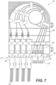
FIG. 7 is a top view of the exemplary carriage ofFIG. 1 in a fifth exemplary use configuration. -
FIG. 8 is a top view of the exemplary carriage ofFIG. 1 in a sixth exemplary use configuration. -
FIG. 9 illustrates an exemplary fiber distribution cabinet containing the exemplary carriage ofFIG. 1 . -
FIG. 10 illustrates a plurality of the exemplary carriages ofFIG. 1 mounted to a rear wall of a fiber distribution cabinet in a zero U-space arrangement. -
FIGS. 11A and 11B illustrate the exemplary carriage ofFIG. 1 mounted to a rack chassis of a fiber distribution cabinet in a zero U-space arrangement. -
FIG. 12 illustrates a plurality of the exemplary carriages ofFIG. 1 mounted to a rack chassis of a fiber distribution cabinet. -
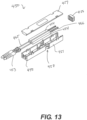
FIG. 13 is a perspective view of an exemplary splitter in accordance with various aspects of the disclosure. -
FIG. 14 is a perspective view of another exemplary splitter in accordance with various aspects of the disclosure. -
FIG. 15 is a perspective view of the exemplary splitter mounted to a fiber distribution panel in accordance with various aspects of the disclosure -
FIG. 16 is a perspective view of the exemplary splitter in a standalone configuration in accordance with various aspects of the disclosure. - Although certain embodiments of the present invention are shown and described in detail, it should be understood that various changes and modifications may be made without departing from the scope of the appended claims. The scope of the present invention will in no way be limited to the number of constituting components, the materials thereof, the shapes thereof, the relative arrangement thereof, etc., and are disclosed simply as an example of embodiments of the present invention.
- As a preface to the detailed description, it should be noted that, as used in this specification and the appended claims, the singular forms "a," "an," and "the" include plural referents, unless the context clearly dictates otherwise.
- Referring to the drawings,
FIGS. 1-7 depict an exemplary embodiment of acarriage 100 accableing to various aspects of the disclosure. Thecarriage 100 is configured to be mounted in any enclosure or cabinet, as will be discussed below. - The
carriage 100 includes a carriage body 101 having afront end 102, arear end 104, afirst side 106, and asecond side 108. Thefront end 102 includes a plurality ofopenings 110. In theexemplary carriage 100 shown inFIGS. 1-7 , thefront end 102 includes sevenopenings 110. However, it should be appreciated that thefront end 102 could have more than or less than seven openings. In theexemplary carriage 100 shown inFIGS. 1-6 , each of theopenings 110 is sized and configured to receive an SC (Subscriber Connector) simplex adapter, which is the same size as an LC (Lucent Connector) duplex adapter, for example, via an interference fit, a snap-fit, or the like. Such anopening 110 also permits passage of fiber optic patch cables and/or a fiber cable harness, for example, an IFC (interfacility fiber cable assembly) harness. However, it should be appreciated that theopenings 110 could be configured with any desired shape and size and/or one or more of the openings may be shaped and/or sized differently than others of the openings. - The
carriage 100 includes aninterior cavity 112 in which fiber optic cables and/or fiber optic components are disposed. Thecavity 112 is delimited by thefront end 102, therear end 104, thefirst side 106, thesecond side 108, and a back wall 114. In some embodiments, atop 116 of thecarriage 100 may be open to allow access to the fiber optic cables and/or fiber optic components disposed therein. In some embodiments, the carriage may include a cover (not shown) that is removably attachable to thetop 116 of thecarriage 100 to allow access to the fiber optic cables and/or fiber optic components disposed therein. - As shown in
FIGS. 1-7 , thecarriage 100 includes a plurality of fiber management features disposed in thecavity 112. For example, thecarriage 100 includes amandrel 120 extending perpendicular from the plane of the back wall 114 into thecavity 112. Themandrel 120 can be a full circle, as shown, or a partial circle configured to guide fiber optic cable along a desired path within thecavity 112. Themandrel 120 may include one ormore fingers 122 extending from themandrel 120 near the top 116 of thecarriage 100 in a direction parallel to the plane of the back wall 114. Thefingers 122 are configured to retain the fiber optic cables in thecavity 112. Thecarriage 100 may include one or moreadditional guides 126 that extend perpendicular from the plane of the back wall 114. Theguides 126 may also include one ormore fingers 128 extending from theguides 126 near the top 116 of thecarriage 100 in a direction parallel to the plane of the back wall 114. Thefingers 128 are configured to retain the fiber optic cables in thecavity 112, as will be discussed in more detail below. In one embodiment, there are twoguides 126 that fan out the fiber cables for directional distribution. However, more orless guides 126 may be needed based on the bend tolerance specification of the particular fiber cables used. - The
mandrel 120, theguides 126, and thefingers mandrel 120 and theguides 126 define a plurality of curved channels for receiving the fiber cables. The curved channels defined by themandrel 120 and theguides 126 can have specific radii that do not allow the fiber cables to bend more than the specification of the fiber cable allows, thereby minimizing bend loss within fiber cables. Thus, themandrel 120 and theguides 122 provide a convenient and organized way to route the fiber cables through thecarriage 100 and to maintain the fiber cable signal integrity. - Referring again to
FIGS. 1-7 , each of theopenings 110 at thefront end 102 of thecarriage 100 may be delimited by the back wall 114, a pair ofside walls 115, and atop wall 117. In some aspects, theside walls 115 may extend from the back wall 114 to thetop wall 117. In other aspects, one or more of theside walls 115 may extend only part of theway 117 from the back wall 114 toward thetop wall 117. The top wall may include a plurality ofslots 130, with each one of the plurality ofslots 130 being associated with a respective one of theopenings 110. Theslots 130 are sufficiently wide to allow a fiber cable of a patch cable to be inserted into and/or removed from the opening through theslot 130, while being sufficiently narrow to prevent a splitter or an adapter in theopening 110 from being inserted into and/or removed from theopening 110 through theslot 130. - The
carriage 100 may include a second top wall 119 including a plurality oftabs 134 that are spaced from thefront end 102 in a first direction parallel to the plane of the back wall 114 and spaced from the back wall 114 in a second direction perpendicular to the plane of the back wall 114. Thetabs 134 are separated from one another byspaces 136 that are sized and configured to allow a fiber cable of a patch cable to be inserted into and/or removed from the opening through theslot 130, while being sufficiently narrow to prevent a splitter or an adapter in theopening 110 from being inserted into and/or removed from theopening 110 through theslot 130. Thetabs 134 are configured to cooperate with theside walls 115 to securely retain an optical fiber component, for example, a splitter, that is inserted into thecavity 112 through one of theopenings 110. In some aspects, one or more of theside walls 115 may include an engagement structure (not shown) that is configured to engage an engagement structure on a splitter (seeFIG. 13 ) that is inserted into thecavity 112 through one of theopenings 110, as would be understood by persons of ordinary skill in the art. - In some embodiments, the
first side 106 may include one or more spring locking clips 140 configured to couple thecarriage 100 with a key slot in a wall of a cabinet. Thesecond side 108 may include agripping structure 142 that facilitates insertion and/or removal of thecarriage 100 into/from a cabinet or enclosure. For example, the grippingstructure 142 may include awall 144 that has a thickness that is less than a depth of thecarriage 100 such that a user can grip the grippingstructure 142 with his/her fingers when a plurality ofcarriages 100 are arranged in close proximity to one another in the cabinet. In some aspects, the grippingstructure 142 may include a surface having a series ofridges 146 or knurls that facilitate gripping by the user. - Referring now to
FIG. 2 , a first exemplary use configuration of thecarriage 100 is illustrated and described. In the embodiment ofFIG. 2 , a plurality offiber optic adapters 250, for example LC duplex adapters, are inserted into theopenings 110 at thefront end 102 of thecarriage 100.FIG. 2 shows sixadapters 250 inserted into six of theopenings 110. The seventh opening 110' receives twelvefiber patch cables 260 that enter thecarriage 100 at thefront end 102, are directed toward therear end 104, and are guided around themandrel 120. Thefiber patch cables 260 are guided by themandrel 120, theguides 126, and/or one of the walls of thecarriage 100 back toward thefront end 102 of thecarriage 100. Each of thefiber patch cables 260 has a first end terminated with afiber optic connector 262, for example, an LC connector, which is connected to arear side 252 of thefiber optic adaptors 250. A second end (not shown) of the each of thefiber patch cables 260 may include a connector (not shown) that is configured to be connected to another fiber optic component, for example, in the cabinet within which thecarriage 100 is disposed. - As illustrated, twelve
simplex LC cables 260 are connected to sixLC duplex adaptors 250. In other embodiments, six duplex cables can be connected to the six LC duplex adapters. It should be appreciated that SC cables and adapters can be used in place of one or more of the LC cables and adapters. In fact, the principle of this embodiment would be possible with any type of adaptor and cable subject to box design, box size, and aperture shape (for the adaptor), such as, for example, MPO connectors. - Because the
patch cables 260 and thebulkhead adapters 250 are disposed at thefront end 102 of the carriage, there is no need to access the rear of the patch panel/field in order to make rear bulkhead connections. Instead, all connection ports are accessible from one side, i.e., thefront end 102, of thecarriage 100, which makes it easier for a technician to make moves, additions, and changes. - As will be described in more detail below, the
carriage 100 can be used in a data center server cabinet and occupy "zero space" in the rack or chassis that is disposed in the cabinet. Thecarriage 100 can be used in any FTTX any application requiring patch cable connections from one side. For example, thecarriage 100 can be used in wall-mounted cabinets where cables enter and exit from the bottom only, pole mounted applications where cables enter or exit from one side only, and/or street cabinet applications where the patch field needs to be managed in tight space-limited areas or in the upper corner of the cabinet. - Referring now to
FIG. 3 , a second exemplary use configuration of thecarriage 100 is illustrated and described. The configuration ofFIG. 3 is only different from that ofFIG. 2 in that a multi-fiber harness 364, for example, a twelve fiber harness, which includes twelve LCsimplex cables 360, is inserted into the seventh opening 110'. The harness 364 may facilitate quicker installation by a technician than the twelve separate patch cables of the configuration ofFIG. 2 . Thefiber cables 360 are guided by themandrel 120, theguides 126, and/or one of the walls of thecarriage 100 back toward thefront end 102 of thecarriage 100. Each of thefiber cables 360 has a first end terminated with afiber optic connector 362, for example, an LC connector, which is connected to arear side 252 of thebulkhead adaptors 250. The harness 364 may include amulti-fiber cable 366 that extends out through the seventh opening 110' and is configured to be connected to another fiber optic component, for example, in the cabinet within which thecarriage 100 is disposed. - As illustrated, twelve simplex LC cables are connected to six LC duplex adaptors. In other embodiments, the harness 364 may include six uniboot LC cores configured to be connected to the six LC duplex adapters. It should be appreciated that SC cables and adapters can be used in place of one or more of the LC cables and adapters. In fact, the principle of this embodiment would be possible with any type of adaptor and cable subject to box design, box size, and aperture shape (for the adaptor).
- Referring now to
FIGS. 4 and5 , a third exemplary use configuration of thecarriage 100 is illustrated and described. In the configuration ofFIGS. 4 and5 ,preconnectorized splitter modules 450 are inserted into theopenings 110 at thefront end 102 of thecarriage 100.FIG. 4 shows six fiberoptic splitter modules 450 inserted into six of theopenings 110. Thesplitter modules 450 includeinput fiber cables 452 that are guided by themandrel 120, theguides 126, and/or one of the walls of thecarriage 100 back toward theback end 104 of thecarriage 100 and around themandrel 120 toward thefront end 102 of thecarriage 100 where they can exit thecarriage 100 via the seventh opening 110'. Theinput fiber cables 452 may each include aboot 453 configured to provide strain relief to thecables 452 at an interface with thesplitter module 450. - The
input cables 452 each include an end, distal from thesplitter module 450, having a fiber optic connector (not shown) that is configured to be connected to another fiber optic component, for example, in the cabinet within which thecarriage 100 is disposed. Thepreconnectorized splitter modules 450 includesoutput fiber cables 456 that have an end (not shown), distal from thesplitter module 450, having a fiber optic connector (not shown) that is configured to be connected to another fiber optic component, for example, in the cabinet within which thecarriage 100 is disposed. - The
slots 130 at the front end of thecarriage 100 andspaces 136 betweentabs 134 permit theinput cables 452 of thesplitter modules 450 to be inserted into thecavity 112 to be guided by themandrel 120 and theguides 126. For example, theoutput fiber cables 456 of one of thesplitters 450 can be inserted through theopenings 130 andspaces 136 with thesplitter module 450 toward therear end 104 of thecarriage 100. After theoutput fiber cables 456 are in theopening 110, thesplitter 450 can be moved toward thefront end 102 and into theopening 110. As mentioned above, theside walls 115 may be configured to securely retain thesplitter modules 450 in thecarriage 100. - According to this configuration,
splitter modules 450 can be added and/removed one at a time. Thus, in the case of a problem with an end user associated with one of theoutput cables 456, only one of the splitter bodies 454 would need to be removed and/or replaced, and thus only a fraction of the end users serviced by thecarriage 100 would be affected during the removal and/or replacement. - Referring to
FIG. 13 , thesplitter modules 450 include asplitter body 451, one or more splitters 454, aforward wall 455, arear wall 456, and acover 457. Thesplitter body 451 may include anengagement feature 458 configured to be coupled with an engagement feature of at least one of theside walls 115 of theopenings 110. For example, theengagement feature 458 may comprise a flexible finger and a projection. The flexible finger is configured to be urged inward when thesplitter module 450 is inserted into the opening, and the projection serves as a stop to limit insertion of themodule 450 into the opening. In some aspect, the engagement feature of theside wall 115 may be configured to be received between the finger and the projection, and theside wall 115 may be configured to allow the finger to flex back outward to retain the engagement feature of the side wall between the finger and the projection. - The
forward wall 455 may include one or more ports configured to receive afiber input cable 465, and therear wall 456 may be removable from thesplitter body 451. Therear wall 456 may include a plurality of openings each configured to receive anoutput fiber cable 466. Thefiber input cables 465 andfiber output cables 466 may be furcation cables (or furcation tubes) configured to receive an optical fiber, and the optical fibers are spliced to the splitter 454. - As illustrated in
FIG. 13 , in some aspects, eachsplitter module 450 may include two splitters 454, and each splitter may be configured as a 1:8 splitter having oneinput fiber 465 and eightoutput fibers 466. Of course, in some aspects, thesplitter module 450 may include one splitter configured as a 1:16 splitter. It should be appreciated that thesplitter modules 450 may contain any other conceivable arrangement of one or more splitters, and the splitters may have higher or lower splitter ratios than 1:8 and 1:16. - Referring to
FIG. 14 , for acarriage 100 having one or morelarger openings 110, a larger splitter module 450' may be inserted into the larger opening. In some aspects, each splitter module 450' may include four splitters 454, and each splitter may be configured as a 1:8 splitter having one input fiber and eight output fibers. Of course, in some aspects, thesplitter module 450 may include one splitter configured as a 1:32 splitter, two splitters configured as 1:16 splitters, etc. It should be appreciated that the splitter modules 450' may contain any other conceivable arrangement of one or more splitters, and the splitters may have higher or lower splitter ratios. - As shown in
FIG. 15 , one or more of theaforementioned splitter modules 450, 450' may be coupled with apanel 590 of a fiber distribution hub independent of thecarriage 100. For example, a splitter holder 570 may be configured to be coupled to the panel, for example, via fasteners or the like. The splitter holder 570 may includearms 571 configured to receive and hold thesplitter modules 450, 450'. - In another embodiment, as illustrated in
FIG. 16 , theaforementioned splitter modules 450, 450' may configured to be used in a manner unattached from thecarriage 100 and the panel. As shown inFIG. 16 , thesplitter module 450, 450' may include a preconnectorizedinput fiber cable 552 and amulti-fiber output cable 566 having abreakout 567 that breaks out the fibers of theoutput fiber cable 566 to a plurality of preconnectorizedoutput fiber cables 569. - Referring now to
FIG. 6 , a fourth exemplary use configuration of thecarriage 100 is illustrated and described. In the configuration ofFIG. 6 , apatch cable 660 is inserted into theopenings 110 at thefront end 102 of thecarriage 100.FIG. 2 shows only one patch cable inserted into one of theopenings 110. However, it should be appreciated than any number ofpatch cables 660 can be inserted into theopenings 110 and thecavity 112, limited only by the size of theopenings 110 and thecarriage 100. Thepatch cable 660 is guided by themandrel 120, at least one of theguides 126, and/or one of the walls of thecarriage 100 back toward theback end 104 of thecarriage 100 and around themandrel 120 toward thefront end 102 of thecarriage 100 where they can exit thecarriage 100 via another one of theopenings 110. Theslots 130 at the front end of thecarriage 100 andspaces 136 betweentabs 134 permit thepatch cable 660 to be inserted into theopenings 110 and into thecavity 112 to be guided by themandrel 120 and theguides 126. - In the embodiment of
FIG. 6 , there is no connectivity inside thecarriage 100, but instead thecarriage 100 is only used as a method of hangingpatch cables 660. Thepatch cables 660 can be hung in the same way that the splitter is so that the cable management is much easier inside of the cabinet. No complex cable management is required inside cabinet for an installer to follow. This arrangement is useful for any application requiring a patch cable to be hung inside a cabinet so that the two individual connectorized ends 666 can be connected to two different ports. - Referring now to
FIG. 7 , a fifth exemplary use configuration of thecarriage 100 is illustrated and described. In the configuration ofFIG. 7 ,preconnectorized splitter modules 450 are inserted into some of theopenings 110 at thefront end 102 of thecarriage 100.FIG. 7 shows four fiberoptic splitter modules 450 inserted into four of theopenings 110. Thesplitter modules 450 includeinput fiber cables 452 that are guided by themandrel 120, theguides 126, and/or one of the walls of thecarriage 100 back toward theback end 104 of thecarriage 100 and around themandrel 120 toward thefront end 102 of thecarriage 100 where they have ends that are terminated with aconnector 462, for example, an LC connector, which is connected to arear side 252 offiber optic adaptors 250, which are received by openings 110' at thefirst end 102 of thecarriage 100.FIG. 7 shows twobulkhead adapters 250, for example, LC duplex adapters, inserted into two of the openings 110'. - It should be appreciated that the universal nature of the
carriage 100 permits thecarriage 100 to include any combination ofadapters 250,patch cables 260, harnesses 364,splitter modules 450, and/orpatch cables 660 desired by a customer. For example, as shown inFIG. 8 , thecarriage 100 may include foursplitter modules 450 and onepatch cable 660. The number and size of these elements are only limited by the size and configuration of thecarriage 100. - Referring now to
FIGS. 9-12 , arrangement of thecarriage 100 in afiber distribution cabinet 980 is illustrated and described.FIG. 9 illustrates a typicalfiber distribution cabinet 980, and thecarriage 100 is mounted in thecabinet 980 in a vertical orientation. That is, thecarriage 100 is mounted with thefront end 102 facing downward, therear end 104 facing upward, thefirst side 106 facing arear wall 982 of thecabinet 980, and thesecond side 108 facing afront 984 of the cabinet, which may be closed by adoor 986. As shown, thecarriage 100 is used for a point-to-point (P2P) patch cable connection, similar to that shown inFIG. 6 . That is, one end of thepatch cable 660 is connected to a Feeder Optical Distribution Frame (ODF), i.e., where the signal is coming from the Head-end/Central Office, and the other end is connected to a Distribution ODF, which is where the signal is being sent to end users. -
FIG. 10 illustrates a plurality of thecarriages 100 mounted in the upper right hand corner of a fiber cabinet in the vertical orientation and in a zero U-space of the cabinet. For example, the one or more spring locking clips 140 may be coupled with key slot(s) on theback wall 982 of thecabinet 980. Thecarriages 100 may be configured according to one of the aforementioned exemplary configurations or with any other desired configuration.FIG. 10 illustrates eightcarriages 100. If thecarriages 100 are configured as shown inFIG. 4 , which includes sixsplitter modules 450, the eightcarriages 100 would include a total of 48splitter modules 450. Eachsplitter module 450 may include two splitters 454, each of which includes a 1:8 splitter, a 1:16 splitter, etc., as described above. -
FIGS. 11A and 11B illustrate another zero U-space mounting position of thecarriage 100 in a cabinet. Zero U-space is a term used when patch panels are fixed somewhere other than between the intended fixing rails of a rack chassis. In this respect, the patch panel occupies no valuable space inside the rack chassis and, thus, the space in the rack chassis can be used for revenue generating servers or switches. Therefore, the carriage can be used for fitting inside standard cabinets that have not been adapted to accept this box, i.e. does not have key slots configured to receive the locking clips 140. For example, in this arrangement, a folded metal plate could be fixed to the standard fixing rail of the rack chassis (behind equipment fixings) and then has a shape which will allow the box to be fixed to the plate. Slots in the rear plate of the bracket would facilitate this arrangement. Referring now toFIG. 12 , it should be appreciated that thecarriage 100 can also be mounted to a 19", 21", or 23" panel, either vertically or horizontally stacked. - It should be appreciated that, in some aspects, the
carriage 100 may be preconnected to and packaged with a fiber optic panel for delivery to an end user. For example, thecarriage 100 may be populated with one or morepreconfigured splitter modules 450, 450' prior to being provided to an end user. Eachsplitter module 450 may include one or more fiber input cables and a plurality of fiber output cables based on the one or more splitters contained in the splitter module. Each of the fiber output cables may be pre-connectorized and inserted into a port of the fiber optic panel, and each of the fiber input cables may be pre-connectorized so that upon delivery to an end user location, only the fiber input cables need to be coupled with an adapter port in order to provide input signals to thesplitter modules 450, 450'. - Additional embodiments include any one of the embodiments described above, where one or more of its components, functionalities or structures is interchanged with, replaced by or augmented by one or more of the components, functionalities, or structures of a different embodiment described above.
- It should be understood that various changes and modifications to the embodiments described herein will be apparent to those skilled in the art. Such changes and modifications can be made without departing from the scope of the present disclosure and without diminishing its intended advantages.
- Although several embodiments of the disclosure have been disclosed in the foregoing specification, it is understood by those skilled in the art that many modifications and other embodiments of the disclosure will come to mind to which the disclosure pertains, having the benefit of the teaching presented in the foregoing description and associated drawings.
- Moreover, although specific terms are employed herein, as well as in the claims which follow, they are used only in a generic and descriptive sense, and not for the purposes of limiting the present disclosure, nor the claims which follow.
Claims (11)
- A carriage (100) configured to be mounted in a fiber distribution cabinet, the carriage (100) comprising:a carriage body (101) having a front end (102), a rear end (104), a first side (106), a second side (108), and a back wall (114) cooperating to define a cavity (112);a top wall (117) at the front end (102) of the carriage body (101);a plurality of side walls (115) extending from the back wall (114) to the top wall (117),wherein the top wall (117), the side walls (115), and the back wall (114) define a plurality of openings (110) at the front end (102) of the carriage body,wherein the plurality of openings (110) are sized and configured to receive a fiber optic component, whereinthe top wall (117) includes a plurality of slots (130), each of the plurality of slots (130) being associated with a respective one of the plurality of openings (110), andwherein the slots (130) are sized and configured to allow fiber optic cables (260) to be inserted into and/or removed from an opening of said plurality of openings (110) through a slot of said plurality of slots (130), while preventing the fiber optic component from being inserted into and/or removed from the opening through the slot.
- The carriage of claim 1, wherein the plurality of openings (110) are sized and configured to receive a fiber optic splitter (450) or a fiber optic adapter (250).
- The carriage of claim 2, wherein the carriage (100) is sized to receive an LC duplex adapter or an SC simplex adapter.
- The carriage of any one of the preceding claims, wherein the cavity (112) is configured to receive fiber optic cables (260) and/or fiber optic components.
- The carriage of any one of the preceding claims, further comprising:
a plurality of fiber management features extending perpendicular to the plane of the back wall (114) and being disposed in the cavity (112), the plurality of fiber management features being configured to route fiber cables (260) to and from the front end (102) of the carriage (100). - The carriage of any one of the preceding claims, wherein the opening is configured to receive the fiber optic component in a direction from the rear end (104) of the carriage (100) toward the front end (102) of the carriage (100).
- The carriage of any one of the claims 1-5, wherein the opening is configured to receive the fiber optic component in a direction from the front end (102) of the carriage (100) toward the rear end (104) of the carriage (100).
- The carriage of any one of the preceding claims, further comprising:
a second top wall (119) spaced from the front end (102) in a first direction parallel to a plane of the back wall (114). - The carriage of claim 8, wherein the second top wall (119) includes a plurality of tabs (134) spaced from the back wall (114) in a second direction perpendicular to the plane of the back wall (114).
- The carriage of claim 9, wherein the tabs (134) are separated from one another by spaces (136) that are sized and configured to allow fiber optic cables (260) to be inserted into and/or removed from the opening through the slot, while preventing the fiber optic component from being inserted into and/or removed from the opening through the slot.
- The carriage of any of claims 8-10, wherein second top wall (119) is configured to cooperate with the side walls (115) to securely retain the optical fiber component that is inserted into the cavity (112) through one of the plurality of openings (110).
Applications Claiming Priority (2)
| Application Number | Priority Date | Filing Date | Title |
|---|---|---|---|
| US201962932456P | 2019-11-07 | 2019-11-07 | |
| PCT/US2020/059756 WO2021092596A1 (en) | 2019-11-07 | 2020-11-09 | Carriage for patching, splitting, and/or guiding fiber optic cables |
Publications (2)
| Publication Number | Publication Date |
|---|---|
| EP4055430A1 EP4055430A1 (en) | 2022-09-14 |
| EP4055430B1 true EP4055430B1 (en) | 2024-07-10 |
Family
ID=73740498
Family Applications (1)
| Application Number | Title | Priority Date | Filing Date |
|---|---|---|---|
| EP20820606.0A Active EP4055430B1 (en) | 2019-11-07 | 2020-11-09 | Carriage for patching, splitting, and/or guiding fiber optic cables |
Country Status (6)
| Country | Link |
|---|---|
| US (2) | US11467359B2 (en) |
| EP (1) | EP4055430B1 (en) |
| CA (1) | CA3158187A1 (en) |
| DK (1) | DK4055430T3 (en) |
| MX (1) | MX2022005344A (en) |
| WO (1) | WO2021092596A1 (en) |
Families Citing this family (9)
| Publication number | Priority date | Publication date | Assignee | Title |
|---|---|---|---|---|
| USD941295S1 (en) * | 2017-10-03 | 2022-01-18 | Corning Research & Development Corporation | Multiport for making optical connections |
| USD941821S1 (en) * | 2017-10-03 | 2022-01-25 | Corning Research & Development Corporation | Multiport for making optical connections |
| USD941296S1 (en) * | 2017-10-03 | 2022-01-18 | Corning Research & Development Corporation | Multiport for making optical connections |
| USD951954S1 (en) * | 2018-03-29 | 2022-05-17 | Corning Research & Development Corporation | Double stack multiport for making optical connections |
| USD1092479S1 (en) | 2018-03-29 | 2025-09-09 | Corning Research & Development Corporation | Double stack multiport for making optical connections |
| CA183730S (en) | 2018-03-29 | 2020-05-26 | Corning Res And Development Corporation | Multiport for making optical connections |
| CN114025548B (en) * | 2021-11-04 | 2023-11-14 | 翔光光通讯器材(昆山)有限公司 | Wire arranging unit |
| US11809001B2 (en) * | 2022-04-07 | 2023-11-07 | Mellanox Technologies Ltd. | Network interface device with external optical connector |
| CN119485073B (en) * | 2024-11-07 | 2026-04-03 | 武汉锐奥特科技有限公司 | A portable switch cabinet for fiber optic switches and its assembly method |
Family Cites Families (17)
| Publication number | Priority date | Publication date | Assignee | Title |
|---|---|---|---|---|
| TW232757B (en) * | 1994-01-21 | 1994-10-21 | Adc Telecommunications Inc | High-density fiber distribution frame |
| US5640476A (en) * | 1995-07-14 | 1997-06-17 | Siecor Corporation | Guide sleeve for fiber optic cable |
| US5740300A (en) * | 1996-05-01 | 1998-04-14 | Scientific-Atlanta, Inc. | Transceiver module support apparatus with fiber management features |
| US6926449B1 (en) * | 2004-02-23 | 2005-08-09 | Corning Cable Systems Llc | Connector port for network interface device |
| US7218827B2 (en) * | 2004-06-18 | 2007-05-15 | Adc Telecommunications, Inc. | Multi-position fiber optic connector holder and method |
| US7346254B2 (en) * | 2005-08-29 | 2008-03-18 | Adc Telecommunications, Inc. | Fiber optic splitter module with connector access |
| JP5292695B2 (en) * | 2007-01-09 | 2013-09-18 | 富士通株式会社 | Wiring connection device |
| US8059932B2 (en) | 2007-10-01 | 2011-11-15 | Clearfield, Inc. | Modular optical fiber cassette |
| US7978951B2 (en) * | 2008-03-28 | 2011-07-12 | Adc Telecommunications, Inc. | Bulkhead with angled openings and method |
| WO2010077856A1 (en) | 2008-12-17 | 2010-07-08 | 3M Innovative Properties Company | Modular fiber distribution unit |
| EP2403082A1 (en) * | 2010-06-29 | 2012-01-04 | British Telecommunications Public Limited Company | Cable guide |
| US8424198B2 (en) * | 2010-10-19 | 2013-04-23 | Charles McCaskey | Wire positioning tool |
| US9851524B2 (en) * | 2014-01-28 | 2017-12-26 | Commscope Technologies Llc | Slidable fiber optic connection module with cable slack management |
| US10444457B2 (en) * | 2014-02-14 | 2019-10-15 | Commscope Connectivity Uk Limited | Managed connectivity in optical distribution frame |
| US10295771B2 (en) * | 2016-05-03 | 2019-05-21 | Corning Optical Communications LLC | Telecommunications terminal with removable modules |
| US10310206B2 (en) * | 2017-05-22 | 2019-06-04 | Go!Foton Holdings, Inc. | Apparatus for cable routing |
| WO2019072783A1 (en) * | 2017-10-09 | 2019-04-18 | CommScope Connectivity Belgium BVBA | Fiber optic telecommunications tray with enhanced accessibility and management |
-
2020
- 2020-11-09 WO PCT/US2020/059756 patent/WO2021092596A1/en not_active Ceased
- 2020-11-09 DK DK20820606.0T patent/DK4055430T3/en active
- 2020-11-09 EP EP20820606.0A patent/EP4055430B1/en active Active
- 2020-11-09 MX MX2022005344A patent/MX2022005344A/en unknown
- 2020-11-09 CA CA3158187A patent/CA3158187A1/en active Pending
- 2020-11-09 US US17/093,629 patent/US11467359B2/en active Active
-
2022
- 2022-09-30 US US17/957,374 patent/US12326605B2/en active Active
Also Published As
| Publication number | Publication date |
|---|---|
| US20230021347A1 (en) | 2023-01-26 |
| WO2021092596A1 (en) | 2021-05-14 |
| US12326605B2 (en) | 2025-06-10 |
| US11467359B2 (en) | 2022-10-11 |
| US20210141182A1 (en) | 2021-05-13 |
| DK4055430T3 (en) | 2024-10-14 |
| CA3158187A1 (en) | 2021-05-14 |
| MX2022005344A (en) | 2022-08-11 |
| EP4055430A1 (en) | 2022-09-14 |
Similar Documents
| Publication | Publication Date | Title |
|---|---|---|
| US12326605B2 (en) | Carriage for patching, splitting, and/or guiding fiber optic cables | |
| US11002933B2 (en) | Telecommunications chassis and module | |
| US8520996B2 (en) | Removably mountable fiber optic terminal | |
| US12169317B2 (en) | Multi-conformable modules for fiber optic cable distribution systems | |
| US10042135B2 (en) | Telecommunications chassis | |
| US6631237B2 (en) | Termination and splice panel | |
| EP2333597B1 (en) | Fiber optic module assembly and associated methods | |
| US20110129186A1 (en) | Fiber Optic Module Assembly and Associated Methods | |
| US20110235985A1 (en) | Movable Adapter Panel | |
| WO2011005461A1 (en) | Fiber optic cable parking device | |
| WO2017192331A1 (en) | Telecommunications terminal with removable modules | |
| US20250291146A1 (en) | Support frame for providing adapter-less connections for fiber optic cables | |
| US11221455B2 (en) | Fiber optic splitter modules and systems | |
| EP2370844A1 (en) | Modular fiber distribution unit | |
| EP2564251B1 (en) | Fiber optic housings with removable panel clips | |
| US20240353645A1 (en) | Telecommunications chassis | |
| EP4502690A1 (en) | Splice tray adapter and organiser |
Legal Events
| Date | Code | Title | Description |
|---|---|---|---|
| STAA | Information on the status of an ep patent application or granted ep patent |
Free format text: STATUS: UNKNOWN |
|
| STAA | Information on the status of an ep patent application or granted ep patent |
Free format text: STATUS: THE INTERNATIONAL PUBLICATION HAS BEEN MADE |
|
| PUAI | Public reference made under article 153(3) epc to a published international application that has entered the european phase |
Free format text: ORIGINAL CODE: 0009012 |
|
| STAA | Information on the status of an ep patent application or granted ep patent |
Free format text: STATUS: REQUEST FOR EXAMINATION WAS MADE |
|
| 17P | Request for examination filed |
Effective date: 20220510 |
|
| AK | Designated contracting states |
Kind code of ref document: A1 Designated state(s): AL AT BE BG CH CY CZ DE DK EE ES FI FR GB GR HR HU IE IS IT LI LT LU LV MC MK MT NL NO PL PT RO RS SE SI SK SM TR |
|
| DAX | Request for extension of the european patent (deleted) | ||
| RAV | Requested validation state of the european patent: fee paid |
Extension state: TN Effective date: 20220510 |
|
| P01 | Opt-out of the competence of the unified patent court (upc) registered |
Effective date: 20230527 |
|
| GRAP | Despatch of communication of intention to grant a patent |
Free format text: ORIGINAL CODE: EPIDOSNIGR1 |
|
| STAA | Information on the status of an ep patent application or granted ep patent |
Free format text: STATUS: GRANT OF PATENT IS INTENDED |
|
| INTG | Intention to grant announced |
Effective date: 20240209 |
|
| GRAS | Grant fee paid |
Free format text: ORIGINAL CODE: EPIDOSNIGR3 |
|
| GRAA | (expected) grant |
Free format text: ORIGINAL CODE: 0009210 |
|
| STAA | Information on the status of an ep patent application or granted ep patent |
Free format text: STATUS: THE PATENT HAS BEEN GRANTED |
|
| AK | Designated contracting states |
Kind code of ref document: B1 Designated state(s): AL AT BE BG CH CY CZ DE DK EE ES FI FR GB GR HR HU IE IS IT LI LT LU LV MC MK MT NL NO PL PT RO RS SE SI SK SM TR |
|
| REG | Reference to a national code |
Ref country code: CH Ref legal event code: EP |
|
| REG | Reference to a national code |
Ref country code: DE Ref legal event code: R096 Ref document number: 602020033849 Country of ref document: DE |
|
| REG | Reference to a national code |
Ref country code: DK Ref legal event code: T3 Effective date: 20241011 |
|
| REG | Reference to a national code |
Ref country code: NL Ref legal event code: FP |
|
| REG | Reference to a national code |
Ref country code: LT Ref legal event code: MG9D |
|
| PG25 | Lapsed in a contracting state [announced via postgrant information from national office to epo] |
Ref country code: PT Free format text: LAPSE BECAUSE OF FAILURE TO SUBMIT A TRANSLATION OF THE DESCRIPTION OR TO PAY THE FEE WITHIN THE PRESCRIBED TIME-LIMIT Effective date: 20241111 |
|
| REG | Reference to a national code |
Ref country code: AT Ref legal event code: MK05 Ref document number: 1702540 Country of ref document: AT Kind code of ref document: T Effective date: 20240710 |
|
| PG25 | Lapsed in a contracting state [announced via postgrant information from national office to epo] |
Ref country code: PT Free format text: LAPSE BECAUSE OF FAILURE TO SUBMIT A TRANSLATION OF THE DESCRIPTION OR TO PAY THE FEE WITHIN THE PRESCRIBED TIME-LIMIT Effective date: 20241111 |
|
| PG25 | Lapsed in a contracting state [announced via postgrant information from national office to epo] |
Ref country code: NO Free format text: LAPSE BECAUSE OF FAILURE TO SUBMIT A TRANSLATION OF THE DESCRIPTION OR TO PAY THE FEE WITHIN THE PRESCRIBED TIME-LIMIT Effective date: 20241010 |
|
| PG25 | Lapsed in a contracting state [announced via postgrant information from national office to epo] |
Ref country code: GR Free format text: LAPSE BECAUSE OF FAILURE TO SUBMIT A TRANSLATION OF THE DESCRIPTION OR TO PAY THE FEE WITHIN THE PRESCRIBED TIME-LIMIT Effective date: 20241011 Ref country code: FI Free format text: LAPSE BECAUSE OF FAILURE TO SUBMIT A TRANSLATION OF THE DESCRIPTION OR TO PAY THE FEE WITHIN THE PRESCRIBED TIME-LIMIT Effective date: 20240710 Ref country code: PL Free format text: LAPSE BECAUSE OF FAILURE TO SUBMIT A TRANSLATION OF THE DESCRIPTION OR TO PAY THE FEE WITHIN THE PRESCRIBED TIME-LIMIT Effective date: 20240710 |
|
| PG25 | Lapsed in a contracting state [announced via postgrant information from national office to epo] |
Ref country code: BG Free format text: LAPSE BECAUSE OF FAILURE TO SUBMIT A TRANSLATION OF THE DESCRIPTION OR TO PAY THE FEE WITHIN THE PRESCRIBED TIME-LIMIT Effective date: 20240710 |
|
| PG25 | Lapsed in a contracting state [announced via postgrant information from national office to epo] |
Ref country code: LV Free format text: LAPSE BECAUSE OF FAILURE TO SUBMIT A TRANSLATION OF THE DESCRIPTION OR TO PAY THE FEE WITHIN THE PRESCRIBED TIME-LIMIT Effective date: 20240710 |
|
| PG25 | Lapsed in a contracting state [announced via postgrant information from national office to epo] |
Ref country code: IS Free format text: LAPSE BECAUSE OF FAILURE TO SUBMIT A TRANSLATION OF THE DESCRIPTION OR TO PAY THE FEE WITHIN THE PRESCRIBED TIME-LIMIT Effective date: 20241110 Ref country code: AT Free format text: LAPSE BECAUSE OF FAILURE TO SUBMIT A TRANSLATION OF THE DESCRIPTION OR TO PAY THE FEE WITHIN THE PRESCRIBED TIME-LIMIT Effective date: 20240710 |
|
| PG25 | Lapsed in a contracting state [announced via postgrant information from national office to epo] |
Ref country code: HR Free format text: LAPSE BECAUSE OF FAILURE TO SUBMIT A TRANSLATION OF THE DESCRIPTION OR TO PAY THE FEE WITHIN THE PRESCRIBED TIME-LIMIT Effective date: 20240710 |
|
| PG25 | Lapsed in a contracting state [announced via postgrant information from national office to epo] |
Ref country code: RS Free format text: LAPSE BECAUSE OF FAILURE TO SUBMIT A TRANSLATION OF THE DESCRIPTION OR TO PAY THE FEE WITHIN THE PRESCRIBED TIME-LIMIT Effective date: 20241010 Ref country code: ES Free format text: LAPSE BECAUSE OF FAILURE TO SUBMIT A TRANSLATION OF THE DESCRIPTION OR TO PAY THE FEE WITHIN THE PRESCRIBED TIME-LIMIT Effective date: 20240710 |
|
| PG25 | Lapsed in a contracting state [announced via postgrant information from national office to epo] |
Ref country code: RS Free format text: LAPSE BECAUSE OF FAILURE TO SUBMIT A TRANSLATION OF THE DESCRIPTION OR TO PAY THE FEE WITHIN THE PRESCRIBED TIME-LIMIT Effective date: 20241010 Ref country code: PL Free format text: LAPSE BECAUSE OF FAILURE TO SUBMIT A TRANSLATION OF THE DESCRIPTION OR TO PAY THE FEE WITHIN THE PRESCRIBED TIME-LIMIT Effective date: 20240710 Ref country code: NO Free format text: LAPSE BECAUSE OF FAILURE TO SUBMIT A TRANSLATION OF THE DESCRIPTION OR TO PAY THE FEE WITHIN THE PRESCRIBED TIME-LIMIT Effective date: 20241010 Ref country code: LV Free format text: LAPSE BECAUSE OF FAILURE TO SUBMIT A TRANSLATION OF THE DESCRIPTION OR TO PAY THE FEE WITHIN THE PRESCRIBED TIME-LIMIT Effective date: 20240710 Ref country code: IS Free format text: LAPSE BECAUSE OF FAILURE TO SUBMIT A TRANSLATION OF THE DESCRIPTION OR TO PAY THE FEE WITHIN THE PRESCRIBED TIME-LIMIT Effective date: 20241110 Ref country code: HR Free format text: LAPSE BECAUSE OF FAILURE TO SUBMIT A TRANSLATION OF THE DESCRIPTION OR TO PAY THE FEE WITHIN THE PRESCRIBED TIME-LIMIT Effective date: 20240710 Ref country code: GR Free format text: LAPSE BECAUSE OF FAILURE TO SUBMIT A TRANSLATION OF THE DESCRIPTION OR TO PAY THE FEE WITHIN THE PRESCRIBED TIME-LIMIT Effective date: 20241011 Ref country code: FI Free format text: LAPSE BECAUSE OF FAILURE TO SUBMIT A TRANSLATION OF THE DESCRIPTION OR TO PAY THE FEE WITHIN THE PRESCRIBED TIME-LIMIT Effective date: 20240710 Ref country code: ES Free format text: LAPSE BECAUSE OF FAILURE TO SUBMIT A TRANSLATION OF THE DESCRIPTION OR TO PAY THE FEE WITHIN THE PRESCRIBED TIME-LIMIT Effective date: 20240710 Ref country code: BG Free format text: LAPSE BECAUSE OF FAILURE TO SUBMIT A TRANSLATION OF THE DESCRIPTION OR TO PAY THE FEE WITHIN THE PRESCRIBED TIME-LIMIT Effective date: 20240710 Ref country code: AT Free format text: LAPSE BECAUSE OF FAILURE TO SUBMIT A TRANSLATION OF THE DESCRIPTION OR TO PAY THE FEE WITHIN THE PRESCRIBED TIME-LIMIT Effective date: 20240710 |
|
| REG | Reference to a national code |
Ref country code: DE Ref legal event code: R097 Ref document number: 602020033849 Country of ref document: DE |
|
| PG25 | Lapsed in a contracting state [announced via postgrant information from national office to epo] |
Ref country code: SM Free format text: LAPSE BECAUSE OF FAILURE TO SUBMIT A TRANSLATION OF THE DESCRIPTION OR TO PAY THE FEE WITHIN THE PRESCRIBED TIME-LIMIT Effective date: 20240710 Ref country code: RO Free format text: LAPSE BECAUSE OF FAILURE TO SUBMIT A TRANSLATION OF THE DESCRIPTION OR TO PAY THE FEE WITHIN THE PRESCRIBED TIME-LIMIT Effective date: 20240710 |
|
| PG25 | Lapsed in a contracting state [announced via postgrant information from national office to epo] |
Ref country code: EE Free format text: LAPSE BECAUSE OF FAILURE TO SUBMIT A TRANSLATION OF THE DESCRIPTION OR TO PAY THE FEE WITHIN THE PRESCRIBED TIME-LIMIT Effective date: 20240710 |
|
| PG25 | Lapsed in a contracting state [announced via postgrant information from national office to epo] |
Ref country code: CZ Free format text: LAPSE BECAUSE OF FAILURE TO SUBMIT A TRANSLATION OF THE DESCRIPTION OR TO PAY THE FEE WITHIN THE PRESCRIBED TIME-LIMIT Effective date: 20240710 |
|
| PG25 | Lapsed in a contracting state [announced via postgrant information from national office to epo] |
Ref country code: SK Free format text: LAPSE BECAUSE OF FAILURE TO SUBMIT A TRANSLATION OF THE DESCRIPTION OR TO PAY THE FEE WITHIN THE PRESCRIBED TIME-LIMIT Effective date: 20240710 Ref country code: IT Free format text: LAPSE BECAUSE OF FAILURE TO SUBMIT A TRANSLATION OF THE DESCRIPTION OR TO PAY THE FEE WITHIN THE PRESCRIBED TIME-LIMIT Effective date: 20240710 |
|
| PLBE | No opposition filed within time limit |
Free format text: ORIGINAL CODE: 0009261 |
|
| STAA | Information on the status of an ep patent application or granted ep patent |
Free format text: STATUS: NO OPPOSITION FILED WITHIN TIME LIMIT |
|
| 26N | No opposition filed |
Effective date: 20250411 |
|
| REG | Reference to a national code |
Ref country code: CH Ref legal event code: PL |
|
| PG25 | Lapsed in a contracting state [announced via postgrant information from national office to epo] |
Ref country code: MC Free format text: LAPSE BECAUSE OF FAILURE TO SUBMIT A TRANSLATION OF THE DESCRIPTION OR TO PAY THE FEE WITHIN THE PRESCRIBED TIME-LIMIT Effective date: 20240710 |
|
| PG25 | Lapsed in a contracting state [announced via postgrant information from national office to epo] |
Ref country code: LU Free format text: LAPSE BECAUSE OF NON-PAYMENT OF DUE FEES Effective date: 20241109 |
|
| REG | Reference to a national code |
Ref country code: CH Ref legal event code: PL |
|
| PG25 | Lapsed in a contracting state [announced via postgrant information from national office to epo] |
Ref country code: CH Free format text: LAPSE BECAUSE OF NON-PAYMENT OF DUE FEES Effective date: 20241130 |
|
| REG | Reference to a national code |
Ref country code: BE Ref legal event code: MM Effective date: 20241130 |
|
| PG25 | Lapsed in a contracting state [announced via postgrant information from national office to epo] |
Ref country code: SE Free format text: LAPSE BECAUSE OF FAILURE TO SUBMIT A TRANSLATION OF THE DESCRIPTION OR TO PAY THE FEE WITHIN THE PRESCRIBED TIME-LIMIT Effective date: 20240710 |
|
| PG25 | Lapsed in a contracting state [announced via postgrant information from national office to epo] |
Ref country code: BE Free format text: LAPSE BECAUSE OF NON-PAYMENT OF DUE FEES Effective date: 20241130 |
|
| PG25 | Lapsed in a contracting state [announced via postgrant information from national office to epo] |
Ref country code: FR Free format text: LAPSE BECAUSE OF NON-PAYMENT OF DUE FEES Effective date: 20241130 |
|
| PG25 | Lapsed in a contracting state [announced via postgrant information from national office to epo] |
Ref country code: IE Free format text: LAPSE BECAUSE OF NON-PAYMENT OF DUE FEES Effective date: 20241109 |
|
| PGFP | Annual fee paid to national office [announced via postgrant information from national office to epo] |
Ref country code: NL Payment date: 20251126 Year of fee payment: 6 |
|
| PGFP | Annual fee paid to national office [announced via postgrant information from national office to epo] |
Ref country code: DE Payment date: 20251128 Year of fee payment: 6 |
|
| PGFP | Annual fee paid to national office [announced via postgrant information from national office to epo] |
Ref country code: GB Payment date: 20251127 Year of fee payment: 6 |
|
| PGFP | Annual fee paid to national office [announced via postgrant information from national office to epo] |
Ref country code: DK Payment date: 20251125 Year of fee payment: 6 |
|
| PG25 | Lapsed in a contracting state [announced via postgrant information from national office to epo] |
Ref country code: HU Free format text: LAPSE BECAUSE OF FAILURE TO SUBMIT A TRANSLATION OF THE DESCRIPTION OR TO PAY THE FEE WITHIN THE PRESCRIBED TIME-LIMIT; INVALID AB INITIO Effective date: 20201109 |
|
| PG25 | Lapsed in a contracting state [announced via postgrant information from national office to epo] |
Ref country code: CY Free format text: LAPSE BECAUSE OF FAILURE TO SUBMIT A TRANSLATION OF THE DESCRIPTION OR TO PAY THE FEE WITHIN THE PRESCRIBED TIME-LIMIT; INVALID AB INITIO Effective date: 20201109 |