EP4055221B1 - Method of producing a tufting tool - Google Patents
Method of producing a tufting tool Download PDFInfo
- Publication number
- EP4055221B1 EP4055221B1 EP20799853.5A EP20799853A EP4055221B1 EP 4055221 B1 EP4055221 B1 EP 4055221B1 EP 20799853 A EP20799853 A EP 20799853A EP 4055221 B1 EP4055221 B1 EP 4055221B1
- Authority
- EP
- European Patent Office
- Prior art keywords
- tufting
- cavity
- tool
- tufting tool
- insert
- Prior art date
- Legal status (The legal status is an assumption and is not a legal conclusion. Google has not performed a legal analysis and makes no representation as to the accuracy of the status listed.)
- Active
Links
Images


Classifications
-
- D—TEXTILES; PAPER
- D05—SEWING; EMBROIDERING; TUFTING
- D05C—EMBROIDERING; TUFTING
- D05C15/00—Making pile fabrics or articles having similar surface features by inserting loops into a base material
- D05C15/04—Tufting
- D05C15/08—Tufting machines
- D05C15/16—Arrangements or devices for manipulating threads
- D05C15/22—Loop-catching arrangements, e.g. loopers; Driving mechanisms therefor
Definitions
- the present disclosure relates to a method of manufacturing a tufting tool.
- a textile is produced by a textile process in which a thread is inserted on a primary base.
- Specialized machinery can be used to produce a tufted textile.
- Such machinery typically can make use of tufting tools to insert the thread to the primary base and to apply the thread in a described manner.
- the tufting tool is typically made of a steel material.
- the tufting tools are provided in a tufting tool module to facilitate reconfiguration of the machinery for different applications.
- a plurality of tools is embedded within a common cast body member in a side-by-side configuration.
- a tufting machine can hold 2000 needles, hooks and knifes, and they need to match each other with a precision of tenths of a millimeter, or sometimes even hundreds of a millimeter.
- tufting tool modules are described in for example US 4303024 and US 5860373 .
- Some tufting tools are provided with so-called inserts. For example, when the yarn loop in a tufting machine is cut with the knife there is a wear on the cutting edge of the tufting tool being made of a steel material. With some yarns this wear is excessive and in these cases an insert of a hard metal/material is provided on the tufting tool where the wear takes place.
- the hard metal/material can for example be a Tungsten material.
- This insert is typically secured with a brazing process using a heater and brazing paste.
- An insert can therefore typically be a component made of a material harder than the rest of the tufting tool to resist wear on the tufting tool.
- the paste used to join the steel and hard metal during a brazing process is expensive due to its high concentration of rare earth metals, and it releases dangerous fumes when heated, making it hazardous for operators and the environment.
- the paste material is much softer than the steel and the hard metal. This will lead to that, even after the brazing process, the joint of the brazing material is more prone to wear and tear.
- the joint is typically 0.1 - 0.2 mm thick and is exposed to wear by the yarn so it exposes the sharp edge of the hard metal insert. This sharp edge can damage the filaments of the tuft yarn.
- brazing process to provide an insert in a tufting tool is that, due to the complexity of controlling the brazing process, there is a risk for unnecessary high discarding of defect components. For instance, if the amount of brazing paste applied is not correct or the gap between the hard metal and steel for the brazing paste to fill up with capillary action is wrong, it can lead to pores, cracks and cavities in the joint.
- the insert is formed by a filled cavity in the steel material.
- a method of producing a tufting tool with an insert for a tufting machine comprises to form a tufting tool in a first material and to form a cavity in the tufting tool at a location where the insert is to be provided in the tufting tool.
- the cavity is filled with a second material, the second material being a material being harder than the first material.
- the second material can be a granular material or paste.
- the second material is melted to form the insert. The melting can be performed by the use of concentrated energy such as a laser beam or an electron beam.
- the tufting tool is adapted to be used in a tufting machine.
- the tufting tool is formed by a first material.
- the tufting tool comprises an insert of a second material, where the second material is harder than the first material.
- the insert is formed by a cavity in the first material filled with the second, melted, material filling said cavity.
- the cavity in the first material can advantageously be 0.2 - 0.8 mm deep, and in particular 0.3- 0.6 mm deep.
- the first material, from which the tufting tool is made can in accordance with some embodiments be a hardened steel material. In accordance with other embodiments the first material is an un-hardened steel material.
- the second material can for example be one or more of: Hard metal alloy, Tungsten/Wolfram carbide, titanium or chromium.
- the second material is a non-metal material.
- the second material can be a bonding material combined with one or more of: a ceramics material, CBN cubic boron nitride or HPHT diamond or CVD diamond.
- the tufting tool can in accordance with some embodiments be a hook.
- the tufting tool can in accordance with some embodiments be a Level Cut Looper, LCL, hook.
- the invention also extends to a tufting tool module for a tufting machine, where the tufting tool module comprising a plurality of tufting tools according to the above, and a base block where the tufting tools are fixed in the base block for example by casting.
- the outside of the insert is then machined.
- the tufting tool 20 is in Fig. 1 a hook, but in other embodiments other tufting tools can be envisaged such as an LCL hook or some other tufting tool where it can be advantageous to provide an insert.
- the tufting tool 20 comprises a body 22.
- the body 22 can be made of a steel material such as hardened or an unhardened steel material.
- the body 2 can typically be 1-2.5 mm thick.
- the body 22 has a cavity 23 formed therein.
- the cavity can in accordance with some exemplary embodiments have a depth of about 0.2 - 0.8 mm.
- the cavity 23 can be 0.3- 0.6 mm deep.
- the cavity 23 can be formed when manufacturing the body 22.
- the body 22 can be formed from a steel material using electrical discharge machining.
- the cavity 23 can be formed using milling, grinding, electrical discharge machining or using some other type of machining.
- the cavity 23 is machined at a location where an insert is to be provided in the tufting tool.
- the cavity 23 is then filled with a material, in particular a granular material.
- the material filling the cavity 23 is harder than the material used to form the body 22.
- the material in the cavity is then melted.
- the material in the cavity 23 is harder than the material of the body 22.
- the material in the cavity 23 can for example be a hard metal alloy, Tungsten/Wolfram carbide, titanium or chromium or some other hard metal.
- the material in the cavity is a non-metal material.
- the material in the cavity can be a bonding material combined with one or more of: a ceramics material, CBN cubic boron nitride or HPHT diamond or CVD diamond.
- Fig. 2 a perspective view of the hook 20 of Fig. 1 is shown with melted material 24 in the cavity of the body 22.
- a front cross-sectional view of the hook 20 of Fig. 2 is shown in a production state when a cavity is over-filled with material 24 that has been melted.
- the hook 20 has melted material 24 in the cavity of the body 22.
- a front cross-sectional view of the hook 20 of Fig. 2 is shown in a production state when the over-filled cavity with melted material 24 has been machined as will described.
- a view in perspective of a tufting tool module 10 is shown.
- the tufting tool module 10 comprises a plurality of tufting tools 20 as described above.
- the tufting tools 20 are casted in a base block 12.
- the base block 12 can typically be a Zinc block.
- a body of the tufting tool is formed.
- the body of the tufting tool can for example be formed by electrical discharge machining of some suitable material such as a steel material.
- the steel material can for example be a hardened or an un-hardened steel material.
- a cavity is machined in the body.
- the machining of the cavity can in accordance with some embodiments be made in a following step by milling or grinding.
- the machining of the cavity can in accordance with some other embodiments take place at the same time as when the body is machined.
- a hard material being harder than the body is filled in the cavity.
- the material filling the cavity can typically be a granular material or it can be a paste such as a bonding material mixed with a ceramic material or some other suitable material.
- the granular material can be filled via a nozzle running along a computer-controlled path.
- the cavity is over-filled with material.
- the melting can in accordance with some embodiments be performed with the use of concentrated energy, for instance a laser beam, electron beam or similar.
- the granulate is then melted and fills up the cavity with a solid material much harder than the surrounding steel.
- the resulting tufting tool will have a combination of different properties. Wear resistance on the cutting edge is achieved by the melted granulate in the cavity and flexibility of the entire tufting tool is made possible with the surrounding steel.
- the concentrated energy needed to melt the granulate can be concentrated to target only the area that needs to be heated.
- the melting of the hard material typically will not cause the disadvantages of existing methods for providing an insert such as cracks, or deformation.
- an insert is formed in the tufting tool.
- the side of the tufting tool provided with the insert can then be machined in a step 59.
- a plane grinding and / or a profile grinding can be performed to provide an intended shape of the tufting tool.
- the rim that is in contact with a cutting knife can be given a sharp edge.
- Other further machining can also take place depending on the intended use of the tufting tool.
- the insert can be provided in any tufting tool where an insert is desired such as an LCL hook.
Landscapes
- Engineering & Computer Science (AREA)
- Chemical & Material Sciences (AREA)
- Materials Engineering (AREA)
- Textile Engineering (AREA)
- Cutting Tools, Boring Holders, And Turrets (AREA)
Description
- The present disclosure relates to a method of manufacturing a tufting tool.
- In tufting, a textile is produced by a textile process in which a thread is inserted on a primary base. Specialized machinery can be used to produce a tufted textile. Such machinery typically can make use of tufting tools to insert the thread to the primary base and to apply the thread in a described manner. The tufting tool is typically made of a steel material. In some applications the tufting tools are provided in a tufting tool module to facilitate reconfiguration of the machinery for different applications. In a tufting tool module, a plurality of tools is embedded within a common cast body member in a side-by-side configuration. To ensure a good function of the loop forming and a good quality of the tufted fabric, it is essential that the different tufting tools are aligned with each other with very high precision. Typically, a tufting machine can hold 2000 needles, hooks and knifes, and they need to match each other with a precision of tenths of a millimeter, or sometimes even hundreds of a millimeter.
- Known tufting tool modules are described in for example
US 4303024 andUS 5860373 . Some tufting tools are provided with so-called inserts. For example, when the yarn loop in a tufting machine is cut with the knife there is a wear on the cutting edge of the tufting tool being made of a steel material. With some yarns this wear is excessive and in these cases an insert of a hard metal/material is provided on the tufting tool where the wear takes place. - The hard metal/material can for example be a Tungsten material. This insert is typically secured with a brazing process using a heater and brazing paste. An insert can therefore typically be a component made of a material harder than the rest of the tufting tool to resist wear on the tufting tool.
- Known inserts are described
US 2012/0024208 ,EP 1 953290B1 andUS 4155318 . Also,US 2010/010470 describes a tool for a textile machine having a coated recess built from the bottom of the recess. - There is a constant desire to improve textile machines including tufting machines and parts used within such machinery. Hence, there is a need for an improved tufting tool that can be used in a tufting machine.
- It is an object of the present invention to improve tufting machines and in particular to provide an improved method of manufacturing a tufting tool.
- This object and/or others are obtained by the method of producing a tufting tool as set out in the appended claims.
- As has been realized, there are some problems and limitations when joining steel and hard metal with a brazing process or other known processes. For example, in a brazing process, the steel, the brazing paste and the hard metal is heated to several hundred degrees Celsius. All the materials then elongate due to thermal expansion but the steel elongates longer than the hard metal due to the different physical properties of the different materials. Therefore, there is a risk that a high tension is built into the joint between the steel material and the hard metal/material when the materials cool down and shrinks. This in turn can lead to cracking of the hard metal/material component forming the insert.
- Further, the paste used to join the steel and hard metal during a brazing process is expensive due to its high concentration of rare earth metals, and it releases dangerous fumes when heated, making it hazardous for operators and the environment. In addition, the paste material is much softer than the steel and the hard metal. This will lead to that, even after the brazing process, the joint of the brazing material is more prone to wear and tear. The joint is typically 0.1 - 0.2 mm thick and is exposed to wear by the yarn so it exposes the sharp edge of the hard metal insert. This sharp edge can damage the filaments of the tuft yarn.
- Yet another problem with a brazing process to provide an insert in a tufting tool is that, due to the complexity of controlling the brazing process, there is a risk for unnecessary high discarding of defect components. For instance, if the amount of brazing paste applied is not correct or the gap between the hard metal and steel for the brazing paste to fill up with capillary action is wrong, it can lead to pores, cracks and cavities in the joint.
- To reduce, or even eliminate, the problems of known processes for producing a tufting tool with an insert, the insert is formed by a filled cavity in the steel material.
- In accordance with the invention a method of producing a tufting tool with an insert for a tufting machine is provided. The method comprises to form a tufting tool in a first material and to form a cavity in the tufting tool at a location where the insert is to be provided in the tufting tool. The cavity is filled with a second material, the second material being a material being harder than the first material. The second material can be a granular material or paste. The second material is melted to form the insert. The melting can be performed by the use of concentrated energy such as a laser beam or an electron beam.
- The tufting tool is adapted to be used in a tufting machine. The tufting tool is formed by a first material. The tufting tool comprises an insert of a second material, where the second material is harder than the first material. The insert is formed by a cavity in the first material filled with the second, melted, material filling said cavity. Hereby a tufting tool with an insert can be made in a robust and efficient manner. Also, other benefits can be achieved as will be apparent from the description herein.
- The cavity in the first material can advantageously be 0.2 - 0.8 mm deep, and in particular 0.3- 0.6 mm deep.
- The first material, from which the tufting tool is made can in accordance with some embodiments be a hardened steel material. In accordance with other embodiments the first material is an un-hardened steel material.
- The second material can for example be one or more of: Hard metal alloy, Tungsten/Wolfram carbide, titanium or chromium.
- In accordance with some embodiments, the second material is a non-metal material. For example, the second material can be a bonding material combined with one or more of: a ceramics material, CBN cubic boron nitride or HPHT diamond or CVD diamond.
- The tufting tool can in accordance with some embodiments be a hook. The tufting tool can in accordance with some embodiments be a Level Cut Looper, LCL, hook.
- The invention also extends to a tufting tool module for a tufting machine, where the tufting tool module comprising a plurality of tufting tools according to the above, and a base block where the tufting tools are fixed in the base block for example by casting.
- In accordance with some embodiments the outside of the insert is then machined.
- The present invention will now be described in more detail by way of non-limiting examples and with reference to the accompanying drawings, in which:
-
Fig. 1 is a view in perspective of a tufting tool with a cavity, -
Fig. 2 is a view in perspective of a tufting tool with a filled cavity, -
Figs. 3a and 3b are a cross sectional views of a tufting tool with a filled cavity, -
Fig. 4 is a view perspective of a tufting tool module, and -
Fig. 5 is a flow chart illustrating some steps performed when producing a tufting tool with a filled cavity. - In the following an exemplary tufting tool will be described. In the Figures, the same reference numerals designate identical or corresponding elements throughout the several figures. It will be appreciated that these figures are for illustration only and are not in any way restricting the scope of the invention. Also, it is possible to combine features from different described embodiments to meet specific implementation needs. Further, in the description herein a cavity is filled with a melted, hard, material that is cooled. The result is a tufting tool with a filled cavity of a hard material. The filled cavity with hard material is referred to as an insert herein.
- In
Fig. 1 , anexemplary tufting tool 20 is shown. The tufting tool, 20 is inFig. 1 a hook, but in other embodiments other tufting tools can be envisaged such as an LCL hook or some other tufting tool where it can be advantageous to provide an insert. Thetufting tool 20 comprises abody 22. Thebody 22 can be made of a steel material such as hardened or an unhardened steel material. The body 2 can typically be 1-2.5 mm thick. Thebody 22 has acavity 23 formed therein. - The cavity can in accordance with some exemplary embodiments have a depth of about 0.2 - 0.8 mm. In particular the
cavity 23 can be 0.3- 0.6 mm deep. Thecavity 23 can be formed when manufacturing thebody 22. For example, thebody 22 can be formed from a steel material using electrical discharge machining. Thecavity 23 can be formed using milling, grinding, electrical discharge machining or using some other type of machining. - The
cavity 23 is machined at a location where an insert is to be provided in the tufting tool. - The
cavity 23 is then filled with a material, in particular a granular material. The material filling thecavity 23 is harder than the material used to form thebody 22. The material in the cavity is then melted. The material in thecavity 23 is harder than the material of thebody 22. The material in thecavity 23 can for example be a hard metal alloy, Tungsten/Wolfram carbide, titanium or chromium or some other hard metal. In accordance with some embodiments the material in the cavity is a non-metal material. For example, the material in the cavity can be a bonding material combined with one or more of: a ceramics material, CBN cubic boron nitride or HPHT diamond or CVD diamond. - In
Fig. 2 a perspective view of thehook 20 ofFig. 1 is shown with meltedmaterial 24 in the cavity of thebody 22. - In
Fig. 3a , a front cross-sectional view of thehook 20 ofFig. 2 is shown in a production state when a cavity is over-filled withmaterial 24 that has been melted. Thehook 20 has meltedmaterial 24 in the cavity of thebody 22. InFig. 3b a front cross-sectional view of thehook 20 ofFig. 2 is shown in a production state when the over-filled cavity with meltedmaterial 24 has been machined as will described. - In
Fig.4 a view in perspective of atufting tool module 10 is shown. Thetufting tool module 10 comprises a plurality oftufting tools 20 as described above. Thetufting tools 20 are casted in abase block 12. Thebase block 12 can typically be a Zinc block. - In
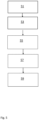
Fig. 5 a flow chart illustrating some steps performed when manufacturing a tufting tool in accordance with the above is shown. First, in astep 51, a body of the tufting tool is formed. The body of the tufting tool can for example be formed by electrical discharge machining of some suitable material such as a steel material. The steel material can for example be a hardened or an un-hardened steel material. Then, in astep 53, a cavity is machined in the body. The machining of the cavity can in accordance with some embodiments be made in a following step by milling or grinding. The machining of the cavity can in accordance with some other embodiments take place at the same time as when the body is machined. Next, in astep 55, a hard material, being harder than the body is filled in the cavity. The material filling the cavity can typically be a granular material or it can be a paste such as a bonding material mixed with a ceramic material or some other suitable material. The granular material can be filled via a nozzle running along a computer-controlled path. In accordance with some embodiments the cavity is over-filled with material. When the cavity has been filled, the material in the cavity is melted in astep 57. The melting can in accordance with some embodiments be performed with the use of concentrated energy, for instance a laser beam, electron beam or similar. The granulate is then melted and fills up the cavity with a solid material much harder than the surrounding steel. Hereby an area of the tufting tool with different characteristics is formed. The resulting tufting tool will have a combination of different properties. Wear resistance on the cutting edge is achieved by the melted granulate in the cavity and flexibility of the entire tufting tool is made possible with the surrounding steel. - Further, the concentrated energy needed to melt the granulate can be concentrated to target only the area that needs to be heated. As a result, the melting of the hard material typically will not cause the disadvantages of existing methods for providing an insert such as cracks, or deformation. There is also no extra material such as brazing paste. This reduces the disadvantages caused by the brazing material such as pores, cracks and cavities in the joint.
- When the material in the cavity has cooled an insert is formed in the tufting tool. The side of the tufting tool provided with the insert can then be machined in a
step 59. For example, a plane grinding and / or a profile grinding can be performed to provide an intended shape of the tufting tool. For instance, the rim that is in contact with a cutting knife can be given a sharp edge. Other further machining can also take place depending on the intended use of the tufting tool. - In the above description a hook has been given as an example. However, the insert can be provided in any tufting tool where an insert is desired such as an LCL hook.
Claims (13)
- A method of producing a tufting tool with an insert for a tufting machine comprising:forming (51) a tufting tool in a first material,forming (53) a cavity at a location in the tufting tool where the insert is to be provided in the tufting tool,filling (55) the cavity with a second material, the second material being a granular material or a paste, and characterised bymelting (57) the second material filled in the cavity to form the insert being harder than the first material.
- The method according to claim 1, wherein the melting is performed by a laser beam or an electron beam.
- The method according to claim 1 or 2, further comprising to machine (59) the tufting tool with the insert formed by the melted second material on the outer surface of the insert.
- The method according to any one of claims 1-3, wherein the cavity is made 0.2 - 0.8 mm deep.
- The method according to any one of claims 1 - 4 , wherein the cavity is made 0.3- 0.6 mm deep.
- The method according to any one of claims 1-5, wherein the first material is a hardened steel material.
- The method according to any one of claims 1-5, wherein the first material is an unhardened steel material.
- The method according to any one of claims 1-7, wherein the second material is one or more of: Hard metal alloy, Tungsten/Wolfram carbide, titanium or chromium.
- The method according to any one of claims 1-7, wherein the second material is a non-metal material.
- The method according to claim 9, wherein the second material is a bonding material combined with a ceramics material.
- The method according to any of claims 1 - 10, wherein said tufting tool is a hook.
- The method according to any of claims 1 - 10, wherein said tufting tool is a Level Cut Looper, LCL, hook.
- The method according to any of claims 1 - 12, further comprising to provide a plurality of tufting tools (20) in a base block (12) with the plurality of tufting tool being fixed in the base block.
Applications Claiming Priority (2)
| Application Number | Priority Date | Filing Date | Title |
|---|---|---|---|
| SE1951277 | 2019-11-07 | ||
| PCT/SE2020/051014 WO2021091451A1 (en) | 2019-11-07 | 2020-10-21 | Tufting tool with insert |
Publications (2)
| Publication Number | Publication Date |
|---|---|
| EP4055221A1 EP4055221A1 (en) | 2022-09-14 |
| EP4055221B1 true EP4055221B1 (en) | 2024-01-31 |
Family
ID=73038369
Family Applications (1)
| Application Number | Title | Priority Date | Filing Date |
|---|---|---|---|
| EP20799853.5A Active EP4055221B1 (en) | 2019-11-07 | 2020-10-21 | Method of producing a tufting tool |
Country Status (5)
| Country | Link |
|---|---|
| US (1) | US11807971B2 (en) |
| EP (1) | EP4055221B1 (en) |
| JP (1) | JP7474845B2 (en) |
| CN (1) | CN114667374A (en) |
| WO (1) | WO2021091451A1 (en) |
Families Citing this family (2)
| Publication number | Priority date | Publication date | Assignee | Title |
|---|---|---|---|---|
| USD1056680S1 (en) | 2021-02-16 | 2025-01-07 | Card-Monroe Corp. | Gauge module |
| US11585029B2 (en) | 2021-02-16 | 2023-02-21 | Card-Monroe Corp. | Tufting maching and method of tufting |
Family Cites Families (12)
| Publication number | Priority date | Publication date | Assignee | Title |
|---|---|---|---|---|
| US3152563A (en) * | 1961-03-15 | 1964-10-13 | Lees & Sons Co James | Tufting machine and looper for producing j-loops |
| CA955127A (en) * | 1970-08-26 | 1974-09-24 | Teijin Limited | Knives for the gru-gru cutter |
| JPS541155A (en) * | 1977-06-02 | 1979-01-06 | Yoshio Yamamoto | Topper in tufting machine |
| US4303024A (en) | 1980-04-26 | 1981-12-01 | Spencer Wright Industries, Inc. | Tufting machine hook module |
| EP0741811B1 (en) | 1994-02-28 | 1997-10-29 | Jos. Zimmermann GmbH & Co. KG | Tufting-tool module |
| EP1908871B1 (en) * | 2006-10-06 | 2019-08-07 | Groz-Beckert KG | Looper for tufting machine |
| EP1953289A1 (en) | 2007-02-01 | 2008-08-06 | Groz-Beckert KG | Hook for a tufting machine |
| EP2182103A1 (en) * | 2008-10-29 | 2010-05-05 | Groz-Beckert KG | Tool for manufacturing textile surfaces |
| PT2412859E (en) * | 2010-07-28 | 2013-03-18 | Groz Beckert Kg | Tufting gripper with spring bearing of an insert |
| EP2412860A1 (en) | 2010-07-28 | 2012-02-01 | Groz-Beckert KG | Looper with double insert body |
| JP6410150B2 (en) * | 2015-03-17 | 2018-10-24 | 三菱日立ツール株式会社 | Laminated molding granules, method for producing the same, and method for producing inserts using the same |
| JP7011548B2 (en) * | 2017-07-14 | 2022-01-26 | キヤノン株式会社 | Powder for ceramic molding, ceramic molding, and its manufacturing method |
-
2020
- 2020-10-21 WO PCT/SE2020/051014 patent/WO2021091451A1/en not_active Ceased
- 2020-10-21 US US17/774,964 patent/US11807971B2/en active Active
- 2020-10-21 CN CN202080075337.2A patent/CN114667374A/en active Pending
- 2020-10-21 JP JP2022522955A patent/JP7474845B2/en active Active
- 2020-10-21 EP EP20799853.5A patent/EP4055221B1/en active Active
Also Published As
| Publication number | Publication date |
|---|---|
| US11807971B2 (en) | 2023-11-07 |
| JP2023501090A (en) | 2023-01-18 |
| CN114667374A (en) | 2022-06-24 |
| WO2021091451A1 (en) | 2021-05-14 |
| EP4055221A1 (en) | 2022-09-14 |
| US20220380955A1 (en) | 2022-12-01 |
| JP7474845B2 (en) | 2024-04-25 |
Similar Documents
| Publication | Publication Date | Title |
|---|---|---|
| US11807971B2 (en) | Tufting tool with insert | |
| EP0720879A2 (en) | Improvements in or relating to elements faced with superhard material | |
| KR101940890B1 (en) | Indexable cutting insert and milling tool | |
| US9238277B2 (en) | Cutting/polishing tool and manufacturing method thereof | |
| US20140321931A1 (en) | Hybrid cutting tool, chip transporting portion and process for producing a cutting tool | |
| US2944323A (en) | Compound tool | |
| US10279408B2 (en) | Ground set saw blade | |
| EP3478439A1 (en) | Method for producing a machining cutting tool via additive laser melting and laser welding, and corresponding machining cutting tool | |
| US3800633A (en) | Method of manufacturing bimetallic high-speed cutting tools | |
| JPWO2012160811A1 (en) | Manufacturing method of three-dimensional shaped object | |
| US10882049B2 (en) | Tool for working abrasive materials | |
| US10213850B2 (en) | Cutting insert, a cutting insert holder, a system including the cutting insert and cutting insert holder, and a method of manufacturing thereof | |
| JPH09158657A (en) | Cutter bit and cutter bit block assembly | |
| US7128066B2 (en) | Diamond tool with metal plate inserted therein | |
| JPH05301104A (en) | Indexable insert, its manufacturing method, and cutting tool | |
| US20220226898A1 (en) | Method for producing an indexable insert and a cutting tool | |
| JPS6364595B2 (en) | ||
| CN103930229B (en) | Reamer and manufacture method thereof | |
| CN106964860B (en) | Method for welding and coating opening | |
| CA2982483C (en) | Pick, in particular a round-shank pick | |
| EP3395523B1 (en) | Cutting tool and method of forming a cutting tool | |
| US2950523A (en) | Cutting tool and method of making | |
| KR20150067441A (en) | Roughing end mill and manufacturing process of the same | |
| KR20090082575A (en) | A diamond tool and method of manufacturing the same | |
| JP6026721B2 (en) | Composite casting tool |
Legal Events
| Date | Code | Title | Description |
|---|---|---|---|
| STAA | Information on the status of an ep patent application or granted ep patent |
Free format text: STATUS: UNKNOWN |
|
| STAA | Information on the status of an ep patent application or granted ep patent |
Free format text: STATUS: THE INTERNATIONAL PUBLICATION HAS BEEN MADE |
|
| PUAI | Public reference made under article 153(3) epc to a published international application that has entered the european phase |
Free format text: ORIGINAL CODE: 0009012 |
|
| STAA | Information on the status of an ep patent application or granted ep patent |
Free format text: STATUS: REQUEST FOR EXAMINATION WAS MADE |
|
| 17P | Request for examination filed |
Effective date: 20220328 |
|
| AK | Designated contracting states |
Kind code of ref document: A1 Designated state(s): AL AT BE BG CH CY CZ DE DK EE ES FI FR GB GR HR HU IE IS IT LI LT LU LV MC MK MT NL NO PL PT RO RS SE SI SK SM TR |
|
| DAV | Request for validation of the european patent (deleted) | ||
| DAX | Request for extension of the european patent (deleted) | ||
| GRAP | Despatch of communication of intention to grant a patent |
Free format text: ORIGINAL CODE: EPIDOSNIGR1 |
|
| STAA | Information on the status of an ep patent application or granted ep patent |
Free format text: STATUS: GRANT OF PATENT IS INTENDED |
|
| INTG | Intention to grant announced |
Effective date: 20231011 |
|
| GRAS | Grant fee paid |
Free format text: ORIGINAL CODE: EPIDOSNIGR3 |
|
| GRAA | (expected) grant |
Free format text: ORIGINAL CODE: 0009210 |
|
| STAA | Information on the status of an ep patent application or granted ep patent |
Free format text: STATUS: THE PATENT HAS BEEN GRANTED |
|
| AK | Designated contracting states |
Kind code of ref document: B1 Designated state(s): AL AT BE BG CH CY CZ DE DK EE ES FI FR GB GR HR HU IE IS IT LI LT LU LV MC MK MT NL NO PL PT RO RS SE SI SK SM TR |
|
| REG | Reference to a national code |
Ref country code: GB Ref legal event code: FG4D Ref country code: CH Ref legal event code: EP |
|
| REG | Reference to a national code |
Ref country code: DE Ref legal event code: R096 Ref document number: 602020025025 Country of ref document: DE |
|
| REG | Reference to a national code |
Ref country code: IE Ref legal event code: FG4D |
|
| REG | Reference to a national code |
Ref country code: LT Ref legal event code: MG9D |
|
| REG | Reference to a national code |
Ref country code: NL Ref legal event code: MP Effective date: 20240131 |
|
| PG25 | Lapsed in a contracting state [announced via postgrant information from national office to epo] |
Ref country code: IS Free format text: LAPSE BECAUSE OF FAILURE TO SUBMIT A TRANSLATION OF THE DESCRIPTION OR TO PAY THE FEE WITHIN THE PRESCRIBED TIME-LIMIT Effective date: 20240531 |
|
| PG25 | Lapsed in a contracting state [announced via postgrant information from national office to epo] |
Ref country code: LT Free format text: LAPSE BECAUSE OF FAILURE TO SUBMIT A TRANSLATION OF THE DESCRIPTION OR TO PAY THE FEE WITHIN THE PRESCRIBED TIME-LIMIT Effective date: 20240131 |
|
| PG25 | Lapsed in a contracting state [announced via postgrant information from national office to epo] |
Ref country code: GR Free format text: LAPSE BECAUSE OF FAILURE TO SUBMIT A TRANSLATION OF THE DESCRIPTION OR TO PAY THE FEE WITHIN THE PRESCRIBED TIME-LIMIT Effective date: 20240501 |
|
| REG | Reference to a national code |
Ref country code: AT Ref legal event code: MK05 Ref document number: 1653922 Country of ref document: AT Kind code of ref document: T Effective date: 20240131 |
|
| PG25 | Lapsed in a contracting state [announced via postgrant information from national office to epo] |
Ref country code: RS Free format text: LAPSE BECAUSE OF FAILURE TO SUBMIT A TRANSLATION OF THE DESCRIPTION OR TO PAY THE FEE WITHIN THE PRESCRIBED TIME-LIMIT Effective date: 20240430 Ref country code: HR Free format text: LAPSE BECAUSE OF FAILURE TO SUBMIT A TRANSLATION OF THE DESCRIPTION OR TO PAY THE FEE WITHIN THE PRESCRIBED TIME-LIMIT Effective date: 20240131 Ref country code: NL Free format text: LAPSE BECAUSE OF FAILURE TO SUBMIT A TRANSLATION OF THE DESCRIPTION OR TO PAY THE FEE WITHIN THE PRESCRIBED TIME-LIMIT Effective date: 20240131 |
|
| PG25 | Lapsed in a contracting state [announced via postgrant information from national office to epo] |
Ref country code: ES Free format text: LAPSE BECAUSE OF FAILURE TO SUBMIT A TRANSLATION OF THE DESCRIPTION OR TO PAY THE FEE WITHIN THE PRESCRIBED TIME-LIMIT Effective date: 20240131 |
|
| PG25 | Lapsed in a contracting state [announced via postgrant information from national office to epo] |
Ref country code: AT Free format text: LAPSE BECAUSE OF FAILURE TO SUBMIT A TRANSLATION OF THE DESCRIPTION OR TO PAY THE FEE WITHIN THE PRESCRIBED TIME-LIMIT Effective date: 20240131 |
|
| PG25 | Lapsed in a contracting state [announced via postgrant information from national office to epo] |
Ref country code: RS Free format text: LAPSE BECAUSE OF FAILURE TO SUBMIT A TRANSLATION OF THE DESCRIPTION OR TO PAY THE FEE WITHIN THE PRESCRIBED TIME-LIMIT Effective date: 20240430 Ref country code: NO Free format text: LAPSE BECAUSE OF FAILURE TO SUBMIT A TRANSLATION OF THE DESCRIPTION OR TO PAY THE FEE WITHIN THE PRESCRIBED TIME-LIMIT Effective date: 20240430 Ref country code: NL Free format text: LAPSE BECAUSE OF FAILURE TO SUBMIT A TRANSLATION OF THE DESCRIPTION OR TO PAY THE FEE WITHIN THE PRESCRIBED TIME-LIMIT Effective date: 20240131 Ref country code: LT Free format text: LAPSE BECAUSE OF FAILURE TO SUBMIT A TRANSLATION OF THE DESCRIPTION OR TO PAY THE FEE WITHIN THE PRESCRIBED TIME-LIMIT Effective date: 20240131 Ref country code: IS Free format text: LAPSE BECAUSE OF FAILURE TO SUBMIT A TRANSLATION OF THE DESCRIPTION OR TO PAY THE FEE WITHIN THE PRESCRIBED TIME-LIMIT Effective date: 20240531 Ref country code: HR Free format text: LAPSE BECAUSE OF FAILURE TO SUBMIT A TRANSLATION OF THE DESCRIPTION OR TO PAY THE FEE WITHIN THE PRESCRIBED TIME-LIMIT Effective date: 20240131 Ref country code: GR Free format text: LAPSE BECAUSE OF FAILURE TO SUBMIT A TRANSLATION OF THE DESCRIPTION OR TO PAY THE FEE WITHIN THE PRESCRIBED TIME-LIMIT Effective date: 20240501 Ref country code: FI Free format text: LAPSE BECAUSE OF FAILURE TO SUBMIT A TRANSLATION OF THE DESCRIPTION OR TO PAY THE FEE WITHIN THE PRESCRIBED TIME-LIMIT Effective date: 20240131 Ref country code: ES Free format text: LAPSE BECAUSE OF FAILURE TO SUBMIT A TRANSLATION OF THE DESCRIPTION OR TO PAY THE FEE WITHIN THE PRESCRIBED TIME-LIMIT Effective date: 20240131 Ref country code: BG Free format text: LAPSE BECAUSE OF FAILURE TO SUBMIT A TRANSLATION OF THE DESCRIPTION OR TO PAY THE FEE WITHIN THE PRESCRIBED TIME-LIMIT Effective date: 20240131 Ref country code: AT Free format text: LAPSE BECAUSE OF FAILURE TO SUBMIT A TRANSLATION OF THE DESCRIPTION OR TO PAY THE FEE WITHIN THE PRESCRIBED TIME-LIMIT Effective date: 20240131 |
|
| PG25 | Lapsed in a contracting state [announced via postgrant information from national office to epo] |
Ref country code: PL Free format text: LAPSE BECAUSE OF FAILURE TO SUBMIT A TRANSLATION OF THE DESCRIPTION OR TO PAY THE FEE WITHIN THE PRESCRIBED TIME-LIMIT Effective date: 20240131 Ref country code: PT Free format text: LAPSE BECAUSE OF FAILURE TO SUBMIT A TRANSLATION OF THE DESCRIPTION OR TO PAY THE FEE WITHIN THE PRESCRIBED TIME-LIMIT Effective date: 20240531 |
|
| PG25 | Lapsed in a contracting state [announced via postgrant information from national office to epo] |
Ref country code: SE Free format text: LAPSE BECAUSE OF FAILURE TO SUBMIT A TRANSLATION OF THE DESCRIPTION OR TO PAY THE FEE WITHIN THE PRESCRIBED TIME-LIMIT Effective date: 20240131 Ref country code: PT Free format text: LAPSE BECAUSE OF FAILURE TO SUBMIT A TRANSLATION OF THE DESCRIPTION OR TO PAY THE FEE WITHIN THE PRESCRIBED TIME-LIMIT Effective date: 20240531 Ref country code: PL Free format text: LAPSE BECAUSE OF FAILURE TO SUBMIT A TRANSLATION OF THE DESCRIPTION OR TO PAY THE FEE WITHIN THE PRESCRIBED TIME-LIMIT Effective date: 20240131 Ref country code: LV Free format text: LAPSE BECAUSE OF FAILURE TO SUBMIT A TRANSLATION OF THE DESCRIPTION OR TO PAY THE FEE WITHIN THE PRESCRIBED TIME-LIMIT Effective date: 20240131 |
|
| PG25 | Lapsed in a contracting state [announced via postgrant information from national office to epo] |
Ref country code: DK Free format text: LAPSE BECAUSE OF FAILURE TO SUBMIT A TRANSLATION OF THE DESCRIPTION OR TO PAY THE FEE WITHIN THE PRESCRIBED TIME-LIMIT Effective date: 20240131 |
|
| PG25 | Lapsed in a contracting state [announced via postgrant information from national office to epo] |
Ref country code: SM Free format text: LAPSE BECAUSE OF FAILURE TO SUBMIT A TRANSLATION OF THE DESCRIPTION OR TO PAY THE FEE WITHIN THE PRESCRIBED TIME-LIMIT Effective date: 20240131 |
|
| PG25 | Lapsed in a contracting state [announced via postgrant information from national office to epo] |
Ref country code: CZ Free format text: LAPSE BECAUSE OF FAILURE TO SUBMIT A TRANSLATION OF THE DESCRIPTION OR TO PAY THE FEE WITHIN THE PRESCRIBED TIME-LIMIT Effective date: 20240131 Ref country code: EE Free format text: LAPSE BECAUSE OF FAILURE TO SUBMIT A TRANSLATION OF THE DESCRIPTION OR TO PAY THE FEE WITHIN THE PRESCRIBED TIME-LIMIT Effective date: 20240131 |
|
| PG25 | Lapsed in a contracting state [announced via postgrant information from national office to epo] |
Ref country code: SK Free format text: LAPSE BECAUSE OF FAILURE TO SUBMIT A TRANSLATION OF THE DESCRIPTION OR TO PAY THE FEE WITHIN THE PRESCRIBED TIME-LIMIT Effective date: 20240131 |
|
| PG25 | Lapsed in a contracting state [announced via postgrant information from national office to epo] |
Ref country code: SM Free format text: LAPSE BECAUSE OF FAILURE TO SUBMIT A TRANSLATION OF THE DESCRIPTION OR TO PAY THE FEE WITHIN THE PRESCRIBED TIME-LIMIT Effective date: 20240131 Ref country code: SK Free format text: LAPSE BECAUSE OF FAILURE TO SUBMIT A TRANSLATION OF THE DESCRIPTION OR TO PAY THE FEE WITHIN THE PRESCRIBED TIME-LIMIT Effective date: 20240131 Ref country code: RO Free format text: LAPSE BECAUSE OF FAILURE TO SUBMIT A TRANSLATION OF THE DESCRIPTION OR TO PAY THE FEE WITHIN THE PRESCRIBED TIME-LIMIT Effective date: 20240131 Ref country code: EE Free format text: LAPSE BECAUSE OF FAILURE TO SUBMIT A TRANSLATION OF THE DESCRIPTION OR TO PAY THE FEE WITHIN THE PRESCRIBED TIME-LIMIT Effective date: 20240131 Ref country code: DK Free format text: LAPSE BECAUSE OF FAILURE TO SUBMIT A TRANSLATION OF THE DESCRIPTION OR TO PAY THE FEE WITHIN THE PRESCRIBED TIME-LIMIT Effective date: 20240131 Ref country code: CZ Free format text: LAPSE BECAUSE OF FAILURE TO SUBMIT A TRANSLATION OF THE DESCRIPTION OR TO PAY THE FEE WITHIN THE PRESCRIBED TIME-LIMIT Effective date: 20240131 |
|
| REG | Reference to a national code |
Ref country code: DE Ref legal event code: R097 Ref document number: 602020025025 Country of ref document: DE |
|
| PG25 | Lapsed in a contracting state [announced via postgrant information from national office to epo] |
Ref country code: IT Free format text: LAPSE BECAUSE OF FAILURE TO SUBMIT A TRANSLATION OF THE DESCRIPTION OR TO PAY THE FEE WITHIN THE PRESCRIBED TIME-LIMIT Effective date: 20240131 |
|
| PLBE | No opposition filed within time limit |
Free format text: ORIGINAL CODE: 0009261 |
|
| STAA | Information on the status of an ep patent application or granted ep patent |
Free format text: STATUS: NO OPPOSITION FILED WITHIN TIME LIMIT |
|
| PG25 | Lapsed in a contracting state [announced via postgrant information from national office to epo] |
Ref country code: IT Free format text: LAPSE BECAUSE OF FAILURE TO SUBMIT A TRANSLATION OF THE DESCRIPTION OR TO PAY THE FEE WITHIN THE PRESCRIBED TIME-LIMIT Effective date: 20240131 |
|
| 26N | No opposition filed |
Effective date: 20241101 |
|
| PG25 | Lapsed in a contracting state [announced via postgrant information from national office to epo] |
Ref country code: SI Free format text: LAPSE BECAUSE OF FAILURE TO SUBMIT A TRANSLATION OF THE DESCRIPTION OR TO PAY THE FEE WITHIN THE PRESCRIBED TIME-LIMIT Effective date: 20240131 |
|
| REG | Reference to a national code |
Ref country code: CH Ref legal event code: PL |
|
| PG25 | Lapsed in a contracting state [announced via postgrant information from national office to epo] |
Ref country code: MC Free format text: LAPSE BECAUSE OF FAILURE TO SUBMIT A TRANSLATION OF THE DESCRIPTION OR TO PAY THE FEE WITHIN THE PRESCRIBED TIME-LIMIT Effective date: 20240131 |
|
| PG25 | Lapsed in a contracting state [announced via postgrant information from national office to epo] |
Ref country code: LU Free format text: LAPSE BECAUSE OF NON-PAYMENT OF DUE FEES Effective date: 20241021 |
|
| PG25 | Lapsed in a contracting state [announced via postgrant information from national office to epo] |
Ref country code: FR Free format text: LAPSE BECAUSE OF NON-PAYMENT OF DUE FEES Effective date: 20241031 |
|
| PG25 | Lapsed in a contracting state [announced via postgrant information from national office to epo] |
Ref country code: CH Free format text: LAPSE BECAUSE OF NON-PAYMENT OF DUE FEES Effective date: 20241031 |
|
| PG25 | Lapsed in a contracting state [announced via postgrant information from national office to epo] |
Ref country code: IE Free format text: LAPSE BECAUSE OF NON-PAYMENT OF DUE FEES Effective date: 20241021 |
|
| PGFP | Annual fee paid to national office [announced via postgrant information from national office to epo] |
Ref country code: DE Payment date: 20251020 Year of fee payment: 6 |
|
| PGFP | Annual fee paid to national office [announced via postgrant information from national office to epo] |
Ref country code: GB Payment date: 20251024 Year of fee payment: 6 |
|
| PGFP | Annual fee paid to national office [announced via postgrant information from national office to epo] |
Ref country code: BE Payment date: 20251022 Year of fee payment: 6 Ref country code: TR Payment date: 20251017 Year of fee payment: 6 |
|
| PG25 | Lapsed in a contracting state [announced via postgrant information from national office to epo] |
Ref country code: CY Free format text: LAPSE BECAUSE OF FAILURE TO SUBMIT A TRANSLATION OF THE DESCRIPTION OR TO PAY THE FEE WITHIN THE PRESCRIBED TIME-LIMIT; INVALID AB INITIO Effective date: 20201021 |
|
| PG25 | Lapsed in a contracting state [announced via postgrant information from national office to epo] |
Ref country code: HU Free format text: LAPSE BECAUSE OF FAILURE TO SUBMIT A TRANSLATION OF THE DESCRIPTION OR TO PAY THE FEE WITHIN THE PRESCRIBED TIME-LIMIT; INVALID AB INITIO Effective date: 20201021 |