EP4054246A1 - Neighboring cell measurement method and apparatus - Google Patents
Neighboring cell measurement method and apparatus Download PDFInfo
- Publication number
- EP4054246A1 EP4054246A1 EP19950735.1A EP19950735A EP4054246A1 EP 4054246 A1 EP4054246 A1 EP 4054246A1 EP 19950735 A EP19950735 A EP 19950735A EP 4054246 A1 EP4054246 A1 EP 4054246A1
- Authority
- EP
- European Patent Office
- Prior art keywords
- information
- smtc
- duration
- terminal device
- cell
- Prior art date
- Legal status (The legal status is an assumption and is not a legal conclusion. Google has not performed a legal analysis and makes no representation as to the accuracy of the status listed.)
- Granted
Links
Images


Classifications
-
- H—ELECTRICITY
- H04—ELECTRIC COMMUNICATION TECHNIQUE
- H04W—WIRELESS COMMUNICATION NETWORKS
- H04W48/00—Access restriction; Network selection; Access point selection
- H04W48/08—Access restriction or access information delivery, e.g. discovery data delivery
- H04W48/10—Access restriction or access information delivery, e.g. discovery data delivery using broadcasted information
-
- G—PHYSICS
- G01—MEASURING; TESTING
- G01S—RADIO DIRECTION-FINDING; RADIO NAVIGATION; DETERMINING DISTANCE OR VELOCITY BY USE OF RADIO WAVES; LOCATING OR PRESENCE-DETECTING BY USE OF THE REFLECTION OR RERADIATION OF RADIO WAVES; ANALOGOUS ARRANGEMENTS USING OTHER WAVES
- G01S19/00—Satellite radio beacon positioning systems; Determining position, velocity or attitude using signals transmitted by such systems
- G01S19/01—Satellite radio beacon positioning systems transmitting time-stamped messages, e.g. GPS [Global Positioning System], GLONASS [Global Orbiting Navigation Satellite System] or GALILEO
- G01S19/13—Receivers
- G01S19/24—Acquisition or tracking or demodulation of signals transmitted by the system
- G01S19/25—Acquisition or tracking or demodulation of signals transmitted by the system involving aiding data received from a cooperating element, e.g. assisted GPS
- G01S19/256—Acquisition or tracking or demodulation of signals transmitted by the system involving aiding data received from a cooperating element, e.g. assisted GPS relating to timing, e.g. time of week, code phase, timing offset
-
- H—ELECTRICITY
- H04—ELECTRIC COMMUNICATION TECHNIQUE
- H04W—WIRELESS COMMUNICATION NETWORKS
- H04W48/00—Access restriction; Network selection; Access point selection
- H04W48/16—Discovering, processing access restriction or access information
-
- H—ELECTRICITY
- H04—ELECTRIC COMMUNICATION TECHNIQUE
- H04B—TRANSMISSION
- H04B7/00—Radio transmission systems, i.e. using radiation field
- H04B7/14—Relay systems
- H04B7/15—Active relay systems
- H04B7/185—Space-based or airborne stations; Stations for satellite systems
- H04B7/1853—Satellite systems for providing telephony service to a mobile station, i.e. mobile satellite service
- H04B7/18563—Arrangements for interconnecting multiple systems
-
- H—ELECTRICITY
- H04—ELECTRIC COMMUNICATION TECHNIQUE
- H04W—WIRELESS COMMUNICATION NETWORKS
- H04W24/00—Supervisory, monitoring or testing arrangements
- H04W24/02—Arrangements for optimising operational condition
-
- H—ELECTRICITY
- H04—ELECTRIC COMMUNICATION TECHNIQUE
- H04W—WIRELESS COMMUNICATION NETWORKS
- H04W24/00—Supervisory, monitoring or testing arrangements
- H04W24/10—Scheduling measurement reports ; Arrangements for measurement reports
-
- H—ELECTRICITY
- H04—ELECTRIC COMMUNICATION TECHNIQUE
- H04W—WIRELESS COMMUNICATION NETWORKS
- H04W64/00—Locating users or terminals or network equipment for network management purposes, e.g. mobility management
- H04W64/006—Locating users or terminals or network equipment for network management purposes, e.g. mobility management with additional information processing, e.g. for direction or speed determination
-
- G—PHYSICS
- G01—MEASURING; TESTING
- G01S—RADIO DIRECTION-FINDING; RADIO NAVIGATION; DETERMINING DISTANCE OR VELOCITY BY USE OF RADIO WAVES; LOCATING OR PRESENCE-DETECTING BY USE OF THE REFLECTION OR RERADIATION OF RADIO WAVES; ANALOGOUS ARRANGEMENTS USING OTHER WAVES
- G01S5/00—Position-fixing by co-ordinating two or more direction or position line determinations; Position-fixing by co-ordinating two or more distance determinations
- G01S5/02—Position-fixing by co-ordinating two or more direction or position line determinations; Position-fixing by co-ordinating two or more distance determinations using radio waves
- G01S5/0205—Details
- G01S5/0236—Assistance data, e.g. base station almanac
-
- H—ELECTRICITY
- H04—ELECTRIC COMMUNICATION TECHNIQUE
- H04W—WIRELESS COMMUNICATION NETWORKS
- H04W24/00—Supervisory, monitoring or testing arrangements
- H04W24/08—Testing, supervising or monitoring using real traffic
-
- H—ELECTRICITY
- H04—ELECTRIC COMMUNICATION TECHNIQUE
- H04W—WIRELESS COMMUNICATION NETWORKS
- H04W8/00—Network data management
- H04W8/22—Processing or transfer of terminal data, e.g. status or physical capabilities
-
- H—ELECTRICITY
- H04—ELECTRIC COMMUNICATION TECHNIQUE
- H04W—WIRELESS COMMUNICATION NETWORKS
- H04W84/00—Network topologies
- H04W84/02—Hierarchically pre-organised networks, e.g. paging networks, cellular networks, WLAN [Wireless Local Area Network] or WLL [Wireless Local Loop]
- H04W84/04—Large scale networks; Deep hierarchical networks
- H04W84/06—Airborne or Satellite Networks
Definitions
- the present disclosure relates to the field of communication, and more particularly, to a method and apparatus for measuring a neighbor cell.
- Non-terrestrial networks are a communication scenario of the fifth generation (5G) mobile communication systems.
- NTN fifth generation
- network devices that receive signals sent by terminal devices are no longer base stations fixed on the ground, but network devices located in the air, such as satellites.
- the satellites are moving very fast, causing distances between the satellites and the terminal devices located on the ground to change very quickly.
- distances between low earth orbit (LEO) satellites and the terminal devices can change at a rate of up to 7 kilometers per second (km/s). Therefore, delays of the signals sent by different satellites reaching the terminal devices in the NTNs are quite different.
- LEO low earth orbit
- the terminal devices need to receive and measure signals of a plurality of NTN cells (e.g., satellites) for cell selection or cell reselection, and the network devices can notify the terminal devices of relevant configuration information for cell selection or cell reselection by broadcast.
- the network devices may notify the terminal devices to receive information such as time windows for receiving SS/PBCH blocks (SSBs) of neighbor cells by broadcasting SS/PBCH block measurement timing configuration (SMTC). Since the delays of the signals sent by different satellites reaching the terminal devices in the NTNs are quite different, the terminal devices need to try to receive the SSBs within longer time windows, leading to increasing power consumption of the terminal devices.
- SSBs SS/PBCH blocks
- SMTC SS/PBCH block measurement timing configuration
- the present disclosure provides a method and apparatus for measuring a neighbor cell, which can reduce power consumption of a terminal device.
- a method for measuring a neighbor cell including: receiving SS/PBCH block measurement timing configuration (SMTC) information; and determining an SMTC window according to a positioning capability of a terminal device and the SMTC information, wherein the SMTC window is used to measure the neighbor cell.
- SMTC SS/PBCH block measurement timing configuration
- the above method can be applied to an NTN or a terrestrial communication network.
- the terminal device For a terminal device whose positioning capability meets a requirement, the terminal device can determine a relatively accurate signal delay of the neighbor cell based on its own positioning capability, without eliminating the influence of calculation error of the signal delay by lengthening the SMTC window.
- the method provided by the present disclosure enables the terminal device with the positioning capability meeting the requirement to receive the SSB of the neighbor cell using a shorter SMTC window, thereby reducing the power consumption of the terminal device.
- a method for measuring a neighbor cell including: determining a positioning capability of at least one terminal device, wherein the at least one terminal device belongs to one cell; and sending SS/PBCH block measurement timing configuration (SMTC) information according to the positioning capability, wherein the SMTC information is used to determine a SMTC window required for measuring the neighbor cell.
- SMTC SS/PBCH block measurement timing configuration
- the above method can be applied to an NTN or a terrestrial communication network.
- the terminal device For a terminal device whose positioning capability meets a requirement, the terminal device can determine a relatively accurate signal delay of the neighbor cell based on its own positioning capability, without eliminating the influence of calculation error of the signal delay by lengthening the SMTC window.
- a network device can configure a shorter SMTC window for the terminal device whose positioning capability meets the requirement to reduce the power consumption of the terminal device.
- an apparatus for measuring a neighbor cell can implement functions corresponding to the method in the first aspect, and the functions may be implemented through hardware, and may also be implemented by executing corresponding software through the hardware.
- the hardware or software includes one or more units or modules corresponding to the above-mentioned functions.
- the apparatus is a terminal device or a chip.
- the apparatus may include a processing unit and a transceiving unit.
- the processing unit may be a processor and the transceiver unit may be a transceiver.
- the terminal device may further include a storing unit, which may be a memory.
- the storing unit is configured to store instructions, and the processing unit executes the instructions stored in the storing unit, enabling the terminal device to execute the method described in the first aspect.
- the processing unit may be a processor, and the transceiver unit may be an input/output interface, pin or circuit, etc.
- the processing unit executes instructions stored in the storing unit, enabling the terminal device including the chip to execute the method described in the first aspect.
- the storing unit may be a storing unit in the chip (such as a register, a cache, etc.) or a storing unit outside the chip in the terminal device (such as a read-only memory, a random access memory, etc.).
- an apparatus for measuring a neighbor cell can implement functions corresponding to the method in the second aspect, and the functions may be implemented through hardware, and may also be implemented by executing corresponding software through the hardware.
- the hardware or software includes one or more units or modules corresponding to the above-mentioned functions.
- the apparatus is a network device or a chip.
- the apparatus may include a processing unit and a transceiving unit.
- the processing unit may be a processor and the transceiver unit may be a transceiver.
- the network device may further include a storing unit, which may be a memory.
- the storing unit is configured to store instructions, and the processing unit executes the instructions stored in the storing unit, enabling the network device to execute the method described in the second aspect.
- the processing unit may be a processor, and the transceiver unit may be an input/output interface, pin or circuit, etc.
- the processing unit executes instructions stored in the storing unit, enabling the network device including the chip to execute the method described in the second aspect.
- the storing unit may be a storing unit in the chip (such as a register, a cache, etc.) or a storing unit outside the chip in the network device (such as a read-only memory, a random access memory, etc.).
- a computer-readable storage medium wherein a computer program is stored in the computer-readable storage medium, and the computer program, when executed by a processor, causes the processor to execute the method described in the first aspect.
- a computer-readable storage medium wherein a computer program is stored in the computer-readable storage medium, and the computer program, when executed by a processor, causes the processor to execute the method described in the second aspect.
- a computer program product including computer program codes, which, when executed by a processor, cause the processor to perform the method described in the first aspect.
- a computer program product including computer program codes, which, when executed by a processor, cause the processor to perform the method described in the second aspect.
- a computer program which, when run on a computer, causes the computer to perform the method described in the first aspect.
- a computer program which, when run on a computer, causes the computer to perform the method described in the second aspect.
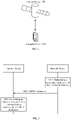
- FIG. 1 is a schematic diagram of a communication system applicable to the present disclosure.
- the communication system 100 includes a network device 110 and a terminal device 120.
- the network device 110 is a network device located in the air, which may be a high altitude platform station (HAPS) with a wireless communication function, and the HAPS may be a hot air balloon, an airplane, a satellite or other aircraft.
- the network device 110 may be a LEO satellite, a medium earth orbit (MEO) satellite, or a geostationary earth orbit (GEO) satellite, where operating periods of the LEO satellite and the MEG satellite are different from a rotation period of the earth and cannot remain relatively stationary with the earth. Therefore, the LEO satellite and the MEG satellite can also be called non-geostationary earth orbit (NGEO) satellites.
- NGEO non-geostationary earth orbit
- the terminal device 120 may be a mobile terminal device or a fixed terminal device.
- the terminal device 120 may be a handheld device with a wireless communication function, a vehicle-mounted device, a wearable device, a computing device or other processing devices connected to wireless modems, such as a user equipment (UE) defined by the 3rd generation partnership project (3GPP), a mobile station (MS), a soft terminal, a home gateway, a set-top box, etc.
- UE user equipment
- 3GPP 3rd generation partnership project
- MS mobile station
- soft terminal a home gateway
- set-top box a set-top box
- a bidirectional arrow line in FIG. 1 represents a signal between the network device 110 and the terminal device 120.
- the satellite can transmit downlink data to the terminal device 120, and the downlink data can be transmitted to the terminal device 120 after channel coding, modulation and mapping.
- the terminal device 120 can also transmit uplink data to the satellite base station, and the uplink data can also be transmitted to the satellite after the channel coding, the modulation and mapping.
- the present disclosure does not limit a communication mode between the network device 110 and the terminal device 120.
- a position where the network device 110 is located may be referred to as a space segment, and a position where the terminal device 120 is located may be referred to as a user segment.
- the communication system 100 may further include a ground segment (not shown in FIG. 1 ), for example, a satellite measurement and control center, a network control center (NCC), various gateways and the like.
- NCC network control center
- the satellite measurement and control center has functions of maintaining, monitoring and controlling an orbital position and attitude of the satellite, managing the ephemeris of the satellite and so on.
- the NCC has functions of handling user registration, identity verification, billing and other network management functions. In some satellite communication systems, the satellite measurement and control center and the NCC are integrated into one.
- the gateway has functions of call processing, switching, interfacing with the terrestrial communication network, and so on.
- the terrestrial communication network is an integral part of the ground segment and is used to send satellite data packets to the terminal device 120 through a core network, that is, the satellite can directly communicate with the terminal device 120 or indirectly communicate with the terminal device 120 through the ground segment.
- the terrestrial communication network can be a public switched telephone network (PSTN), a public land mobile network (PLMN) or other various private networks. Different terrestrial communication networks require the gateway to have different gateway functions.
- the space segment of the satellite communication system may be a multi-layered structure consisting of a management satellite and one or more serving satellites.
- the space segment may include one or more management satellites and serving satellites managed by the managed satellites.
- the satellites mentioned in the present disclosure are not limited to the management satellite or the serving satellite.
- a method for measuring a neighbor cell in an NTN provided by the present disclosure will be introduced in detail in the following.
- the method 200 includes:
- a network device determines a positioning capability of at least one terminal device.
- the at least one terminal device belongs to one cell, which cell may be referred to as a current cell (also called a local cell) of the at least one network device.
- Cells other than the current cell may be referred to as neighbor cells.
- the current cell may be an NTN cell or a non-NTN cell
- the neighbor cell refers to the NTN cell.
- the network devices may be a non-terrestrial network device such as the satellite, or may be a terrestrial network device.
- the positioning capability of the terminal device can be understood as a capability of the terminal device to determine its own position.
- the terminal device can determine its position through the BeiDou navigation satellite system or the global positioning system (GPS), or can determine its position through a base station, a wireless fidelity (Wi-Fi) signal, or a Bluetooth signal, or can determine its position by matching a live street view with a street view map.
- GPS global positioning system
- Wi-Fi wireless fidelity
- Bluetooth Bluetooth
- a satellite-based positioning capability is higher than a base station-based positioning capability.
- the terminal device can more accurately calculate a delay of a signal of the neighbor cell reaching the terminal device, and the terminal device can accurately determine a time domain position and a duration of the SMTC window (that is, a time window for measuring the neighbor cell); and when the positioning capability of the terminal device is low, the terminal device cannot accurately calculate the delay of the signal of the neighbor cell reaching the terminal device, and accordingly, the terminal device cannot accurately determine the time domain position and the duration of the SMTC window.
- the network device needs to determine the positioning capability of the terminal device, so as to send different SMTC information based on different situations.
- the terminal device can report its positioning capability during a capability reporting process.
- the terminal device can report whether it supports satellite positioning; when the terminal device supports the satellite positioning, the terminal device can also report a strength of a current satellite signal, so that the network device can determine the current positioning capability of the terminal device.
- the terminal device may also directly report the current positioning accuracy.
- the network device can determine whether the positioning capability of the terminal device meets a requirement according to a preset condition.
- the preset condition may be a positioning manner of the terminal device or the positioning accuracy of the terminal device.
- the preset condition is that the terminal device needs to be positioned based on the satellite positioning system
- the positioning manner of the terminal device is based on the base station for positioning, the positioning capability of the terminal device does not meet the requirement; if the positioning manner of the terminal device is based on the BeiDou navigation satellite system for positioning, the positioning capability of the terminal device meets the requirement.
- the preset condition is that the positioning accuracy of the terminal device needs to be within 10 meters of error
- the positioning accuracy of the terminal device is greater than 10 meters, the positioning capability of the terminal device does not meet the requirement; and if the positioning accuracy of the terminal device is 5 meters, the positioning capability of the terminal device meets the requirement.
- the present disclosure does not limit a manner in which the network device determines whether the capability of the terminal device meets the requirement.
- the network device According to whether the positioning capability of the at least one terminal device belonging to one cell meets the requirement, the network device has the following processing situations.
- the network device may send the SMTC information including first start time offset information and first duration information.
- the first start time offset information is used to indicate an offset of a start time domain position of the SMTC window relative to a start time domain position of a SMTC period where the SMTC window is located, and the start time domain position of the SMTC period is determined based on a transmission time of the SSB.
- the first duration information is used to indicate a duration of the SMTC window.
- the network device configures the SMTC window for a frequency point, and the first start time offset information may be determined based on the minimum difference between signal delays of all neighbor cells of a frequency point to be measured and a signal delay of the current cell.
- a delay of the signal of the current cell corresponding to the frequency point to be measured reaching the terminal device is 4ms
- the frequency point to be measured corresponds to three neighbor cells
- differences between delays of signals of these three neighbor cells reaching the terminal device and the delay of the signal of the current cell reaching the terminal device are respectively 6ms, 11ms and 16ms
- the offset indicated by the first start time offset information can be 6ms, or can be other values less than 6ms, such as 5ms, to avoid the missing detection of the SSB of the neighbor cell by the terminal device due to the factors such as the calculation error.
- the first duration information may be determined based on an interval between the minimum delay and the maximum delay of signals of all neighbor cells corresponding to the frequency point to be measured.
- the frequency point to be measured corresponds to three neighbor cells
- the delays of the signals of these three neighbor cells reaching the terminal device are respectively 10 ms, 15 ms, and 20 ms
- the minimum delay is 10 ms
- the maximum delay is 20 ms.
- the duration indicated by the first duration information may be a difference between the maximum delay and the minimum delay, that is, 10 ms.
- the duration indicated by the first duration information may also be greater than 10 ms, so as to avoid the missing detection of the SSB of the neighbor cell by the terminal device due to the factors such as the calculation error.
- the network device configures the SMTC window for the neighbor cell, and the first start time offset information may be determined based on a delay of a signal of a neighbor cell to be measured.
- the delay of the signal of the current cell reaching the terminal device is 4ms
- there are three neighbor cells to be measured near the current cell and a difference between a delay of a signal of one of the neighbor cells reaching the terminal device and the delay of the signal of the current cell reaching the terminal device is 6ms
- the offset indicated by the first start time offset information can be 6ms, or it can be other values less than 6ms, such as 5ms, so as to avoid the missing detection of the SSB of the neighbor cell by the terminal device due to the factors such as the calculation error.
- the first duration information may be determined based on an interval between the minimum delay and the maximum delay of signals of the neighbor cell to be measured.
- the duration indicated by the first duration information may be a difference between the maximum delay and the minimum delay, that is, 5ms.
- the duration indicated by the first duration information may also be greater than 5 ms, so as to avoid the missing detection of the SSB of the neighbor cell by the terminal device due to the factors such as the calculation error.
- the satellites of a plurality of neighbor cells corresponding to one frequency point usually include satellites that are far away, and a difference between signal delays of the plurality of neighbor cells is usually greater than the difference between the minimum delay and the maximum delay of the signals of one neighbor cell. Therefore, configuring the SMTC window based on the neighbor cell is beneficial to shorten the duration for the terminal device to measure the neighbor cell, thereby reducing the power consumption of the terminal device.
- the network device configures the SMTC window for a neighbor cell group, and the first start time offset information may be determined based on the minimum delay of signals of a neighbor cell group to be measured.
- the delay of the signal of the current cell reaching the terminal device is 4ms
- there are four neighbor cells to be measured near the current cell which are respectively neighbor cell 1, neighbor cell 2, neighbor cell 3, and neighbor cell 4, and differences between delays of signals of these four neighbor cell reaching the terminal device and the delay of the signal of the current cell reaching the terminal device are respectively 6ms (neighbor cell 1), 8ms (neighbor cell 2), 17ms (neighbor cell 3) and 21ms (neighbor cell 4), and then the network device may group neighbor cells with similar delays into one group, that is, group neighbor cells 1 and 2 into one group, and group neighbor cells 3 and 4 into one group.
- the offset indicated by the first start time offset information may be 6 ms or other values less than 6ms, such as 5ms, so as to avoid the missing detection of the SSB of the neighbor cell by the terminal device due to the factors such as the calculation error.
- the first duration information may be determined based on the interval between the minimum delay and the maximum delay of the signals of the neighbor cell group to be measured.
- the network device may group neighbor cells with similar delays into one group, that is, group neighbor cells 1 and 2 into one group, and group neighbor cells 3 and 4 into one group.
- the duration of the SMTC window indicated by the first duration information may be 2ms, that is, a difference between the minimum delay 10ms and the maximum delay 12ms.
- the duration indicated by the first duration information may also be greater than 2 ms, so as to avoid the missing detection of the SSB of the neighbor cell by the terminal device due to the factors such as the calculation error.
- the satellites of a plurality of neighbor cells corresponding to one frequency point usually include satellites that are far away, and a difference between signal delays of the plurality of neighbor cells is usually greater than the difference between the minimum delay and the maximum delay of the signals of one neighbor cell group. Therefore, configuring the SMTC window based on the neighbor cell group is beneficial to shorten the duration for the terminal device to measure the neighbor cell, thereby reducing the power consumption of the terminal device.
- each of the at least one terminal device has the positioning capability that meets the requirement.
- the network device may send the SMTC information including second start time offset information and second duration information.
- the second start time offset information is used to indicate an offset of a start time domain position of the SMTC window relative to a start time domain position of a SMTC period where the SMTC window is located.
- the second duration information is used to indicate a duration of the SMTC window.
- the network device may determine the second start time offset information according to the delay of the signal of the current cell reaching the terminal device. For example, if the delay of the signal of the current cell reaching the terminal device is 2ms, the offset indicated by the second start time offset information may be 2ms or a value less than 2ms.
- a duration indicated by the second duration information may be a time determined by the network device based on preset information (e.g., a communication standard).
- the terminal device can determine a difference between the signal delay of the neighbor cell and the signal delay of the current cell based on its positioning capability, and adjust the SMTC window indicated by the second start time offset information and the second duration information based on the difference.
- the at least one terminal device includes a terminal device whose positioning capability does not meet the requirement and a terminal device whose positioning capability meets the requirement.
- the network device may send the SMTC information including the following information: the first start time offset information, the second start time offset information, the first duration information and the second duration information.
- the duration indicated by the first duration information is longer than the duration indicated by the second duration information.
- the terminal device whose positioning capability does not meet the requirement has low positioning accuracy, and the signal delay accuracy of the neighbor cell calculated by the network device based on the position of the terminal device is also low, a longer SMTC window needs to be configured to reduce the risk of the missing detection of SSB; and the terminal device whose positioning capability meets the requirement has high positioning accuracy, and the signal delay accuracy of the neighbor cell calculated by the terminal device based on its position is also high, a shorter SMTC window is configured to meet the needs of detecting the SSB. Therefore, the network device can configure the SMTC windows with different lengths for different terminal devices to meet the requirement of different terminal devices.
- the present disclosure does not limit units of a time length, a time offset and a period of the SMTC window.
- the units of the time length o and the time offset of the SMTC window can be a time domain symbol
- the unit of the period corresponding to the SMTC window can be a time slot.
- the network device may send the SMTC information through a system message, which system message is, for example, a system information block (SIB) x, where x is an integer greater than or equal to 1.
- SIB system information block
- the system message may also include at least one frequency point required by the terminal device to measure the neighbor cell, and a neighbor cell list corresponding to each of the at least one frequency point.
- the SMTC information may also contain information indicating the SMTC period.
- the terminal device can perform the following steps.
- the terminal device receives the SMTC information.
- terminal device determines the SMTC window according to the positioning capability and the SMTC information.
- the terminal device may receive the SSB of the neighbor cell according to the SMTC window indicated by the first start time offset information and the first duration information in the SMTC information.
- FIG. 3 shows a method for measuring a neighbor cell by a terminal device whose positioning capability does not meet a requirement.
- the terminal device is UE1
- the three NTN cells are cell 0, cell 1, and cell 2, respectively.
- These three cells send the SSB at the same time, and UE1 resides on cell 0.
- Cell 0 sends the SMTC information associated with frequency point 1 or cell 1 or cell group 1, and UE1 performs the neighbor cell measurement after receiving the SMTC information.
- UE1 measures all neighbor cells corresponding to frequency point 1 according to the SMTC information.
- all neighbor cells corresponding to frequency point 1 are cell 1 and cell 2.
- the SMTC information includes the first start time offset information, and the indicated offset is D1; the SMTC information also includes the first duration information, and the indicated duration L1 is a difference between the signal delay of cell 1 and the signal delay of cell 2.
- UE1 receives the SSBs of cell 1 and cell 2 within the corresponding SMTC window according to D1 and L1 configured by the network device.
- the SMTC information includes the first start time offset information, and the indicated offset is D1; the SMTC information also includes the first duration information, and the indicated duration is L1 (this duration is a duration determined by the network device, which is not related to the difference between the signal delay of cell 1 and the signal delay of cell 2).
- UE1 receives the SSB of cell 1 within the corresponding SMTC window according to D1 and L1 configured by the network device.
- the network device may also send the SMTC information associated with cell 2, so that UE1 can measure cell 2.
- the UE1 measures cell group 1 according to the SMTC information.
- all neighbor cells included in cell group 1 are cell 1 and cell 2.
- the SMTC information includes the first start time offset information, and the indicated offset is D1; the SMTC information also includes the first duration information, and the indicated duration L1 is the difference between the signal delay of cell 1 and the signal delay of cell 2.
- UE1 receives the SSBs of cell 1 and cell 2 within the corresponding SMTC window according to D1 and L1 configured by the network device.
- the terminal device For the terminal device whose positioning capability meets the requirement, it can determine the SMTC window after adjusting the offset indicated by the second start time offset information in the SMTC information, and receive the SSB of the neighbor cell within the SMTC window.
- FIG. 4 is a method for measuring a neighbor cell by a terminal device whose positioning capability meets a requirement.
- the terminal device is UE2
- the three NTN cells are cell 0, cell 1 and cell 2, these three cells send the SSB at the same time, and UE2 resides on cell 0.
- Cell 0 sends the SMTC information associated with frequency point 1 or cell 1 or cell group 1, and UE2 performs the neighbor cell measurement after receiving the SMTC information.
- UE2 measures all neighbor cells corresponding to frequency point 1 according to the SMTC information.
- all neighbor cells corresponding to frequency point 1 are cell 1 and cell 2.
- the SMTC information includes the second start time offset information, and the indicated offset is D0; the SMTC information may also include the second duration information, and the indicated duration is L1.
- UE2 determines that the difference between the signal delay of cell 1 and the signal delay of cell 0 is O1 based on its positioning capability, and UE2 determines that the difference between the signal delay of cell 2 and the signal delay of cell 0 is O2 based on its positioning capability, where O1 is less than O2, then UE2 can adjust DO according to O1, that is, adjust the offset of the start time of the SMTC window to D0+O1.
- the UE2 may also determine that the duration L2 of the SMTC window is the difference between the signal delay of cell 1 and the signal delay of cell 2. Subsequently, UE2 receives the SSBs sent by cell 1 and cell 2 within the corresponding SMTC window based on D0+O1 and L2 determined by itself.
- the SMTC information includes the second start time offset information, and the indicated offset is D0; and the SMTC information may also include the second duration information, and the indicated duration is L1.
- the UE2 determines that the difference between the signal delay of cell 0 and the signal delay of cell 1 is O1 based on its positioning capability, and then UE2 can adjust DO according to O1, that is, adjust the offset of the start time of the SMTC window to D0+O1. Subsequently, the UE2 receives the SSB sent by the cell 1 within the corresponding SMTC window based on D0+O1 determined by itself and L1 configured by the network device.
- the UE2 measures all neighbor cells included in cell group 1 according to the SMTC information.
- all neighbor cells included in cell group 1 are cell 1 and cell 2.
- the SMTC information includes the second start time offset information, and the indicated offset is D0; the SMTC information may also include the second duration information, and the indicated duration is L1.
- UE2 determines that the difference between the signal delay of cell 1 and the signal delay of cell 0 is O1 based on its positioning capability, and UE2 determines that the difference between the signal delay of cell 2 and the signal delay of cell 0 based on its positioning capability is O2, where O1 is less than O2, then UE2 can adjust DO according to O1, that is, adjust the offset of the start time of the SMTC window to D0+O1.
- the UE2 may also determine that the duration L2 of the SMTC window is the difference between the signal delay of cell 1 and the signal delay of cell 2. Subsequently, UE2 receives the SSBs sent by cell 1 and cell 2 within the corresponding SMTC window based on D0+O1 and L2 determined by itself.
- the network device may send the SMTC information including the first start time offset information and the first duration information, or the network device may send the SMTC information including the second start time offset information and the second duration information.
- the following describes a scenario in which the terminal device whose positioning capability meets the requirement and the terminal device whose positioning capability does not meet the requirement coexist with reference to FIG. 5 .
- Fig. 5 there are two terminal devices and three NTN cells in this case.
- the two terminal devices are UE1 and UE2, and the three NTN cells are cell 0, cell 1 and cell 2, respectively. These three cells send the SSB at the same time, and both UE1 and UE2 reside on cell 0.
- Cell 0 sends the SMTC information associated with frequency point 1 or cell 1 or cell group 1, and UE1 and UE2 perform the neighbor cell measurement after receiving the SMTC information.
- the network device can send the SMTC information including two kinds of start time offset information and two kinds of duration information.
- the SMTC information may include the first start time offset information, the first duration information, the second start time offset information, and the second duration information, and the duration indicated by the first duration information is greater than the duration indicated by the second duration information.
- UE1 whose positioning capability does not meet the requirement may determine the SMTC window based on the first start time offset information and the first duration information; and UE2 whose positioning capability meets the requirement may determine the SMTC window based on the second start time offset information and the second duration information.
- a specific manner of UE1 determining the SMTC window may refer to the example corresponding to FIG. 3
- a specific manner of UE2 determining the SMTC window may refer to the example corresponding to FIG. 4 .
- an apparatus for measuring a neighbor cell includes corresponding hardware structures and/or software modules for performing each function.
- the present disclosure may be implemented in a form of hardware or a combination of the hardware and computer software. Whether a function is performed in a form of hardware or computer software driving hardware depends on a particular application and a design constraint condition of the technical solution. A skilled person may use various methods to implement the described functions for each particular application, but such implementation should not be considered to be beyond the scope of the present disclosure.
- Division for functional units may be performed on the apparatus for measuring the neighbor cell according to the above method examples in the present disclosure.
- various functions may be divided into various functional units, or two or more functions may be integrated into one processing unit.
- the above integrated unit may be implemented in a form of hardware, or may be implemented in a form of software function unit. It should be noted that, the division of the units in the present disclosure is illustrative, and is merely the division of logical functions. Other division modes may be used in actual implementations.
- FIG. 6 is a schematic structural diagram of an apparatus for measuring a neighbor cell provided by the present disclosure.
- the apparatus 600 includes a processing unit 610 and a receiving unit 620, and the receiving unit 620 can perform a receiving step under the control of the processing unit 610.
- the receiving unit 620 is configured to receive SMTC information; and the processing unit 610 is configured to determine an SMTC window according to a positioning capability of a terminal device and the SMTC information, and the SMTC window is used to measure the neighbor cell.
- a start time of the SMTC window is a time indicated by first start time offset information in the SMTC information.
- a duration of the SMTC window is a duration indicated by first duration information in the SMTC information.
- the SMTC information further includes second duration information, the duration indicated by the first duration information is longer than a duration indicated by the second duration information, and the second duration information is used to indicate a duration of the SMTC window when the positioning capability meets the requirement.
- the SMTC information is used to configure a SMTC window of a frequency point, or a SMTC window of the neighbor cell, or a SMTC window of a neighbor cell group.
- a start time of the SMTC window is a time obtained by adjusting a time indicated by second start time offset information in the SMTC information, and a time interval between the adjusted time and the time indicated by the second start time offset information is less than or equal to: an interval between a minimum delay of signals of all neighbor cells corresponding to a frequency point corresponding to the SMTC information and a signal delay of an current cell; or, an interval between a signal delay of a neighbor cell corresponding to the SMTC information and the signal delay of the current cell; or, an interval between a minimum delay of signals of a neighbor cell group corresponding to the SMTC information and the signal delay of the current cell.
- a duration of the SMTC window is greater than or equal to: an interval between a maximum delay and a minimum delay of signals of all neighbor cells corresponding to a frequency point corresponding to the SMTC information; or, a duration indicated by second duration information in the SMTC information; or, an interval between a minimum delay and a maximum delay of signals of a neighbor cell group corresponding to the SMTC information.
- the apparatus 600 performs the method for measuring the neighbor cell and the beneficial effects produced, reference may be made to the relevant descriptions in the method embodiments.
- FIG. 7 is a schematic structural diagram of an apparatus for measuring a neighbor cell provided by the present disclosure.
- the apparatus 700 includes a processing unit 710 and a sending unit 720, and the sending unit 720 can perform a sending step under the control of the processing unit 710.
- the processing unit 710 is configured to determine a positioning capability of at least one terminal device, and the at least one terminal device belongs to one cell; and the sending unit 720 is configured to send SMTC information according to the positioning capability, and the SMTC information is used to determine a SMTC window required for measuring the neighbor cell.
- the SMTC information includes first start time offset information, and the first start time offset information is determined based on one of the following conditions: a minimum delay of signals of all neighbor cells corresponding to a frequency point to be measured; a signal delay of a neighbor cell to be measured; and a minimum delay of signals of a neighbor cell group to be measured.
- the SMTC information includes first duration information, and the first duration information is determined based on one of the following conditions: an interval between a minimum delay and a maximum delay of signals of all neighbor cells corresponding to a frequency point to be measured; an interval between a minimum delay and a maximum delay of signals of a neighbor cell to be measured; and an interval between a minimum delay and a maximum delay of signals of a neighbor cell group to be measured.
- the SMTC information includes second duration information, and a duration indicated by the first duration information is longer than a duration indicated by the second duration information, and the second duration information is used to indicate a duration of the SMTC window when the positioning capability meets the requirement.
- the SMTC information includes second start time offset information
- the second start time offset information is determined based on the following conditions: a signal delay of the cell to which the at least one terminal device belongs.
- the apparatus 700 performs the method for measuring the neighbor cell and the beneficial effects produced, reference may be made to the relevant descriptions in the method embodiments.
- FIG. 8 shows a schematic structural diagram of a communication device provided by the present disclosure.
- the dashed line in FIG. 8 indicates that the unit or the module is optional.
- a device 800 may be configured to implement the method described in the above method implementations.
- the device 800 may be a terminal device or a network device or a chip.
- the device 800 includes one or more processors 801, the one or more processors 801 may support the device 800 to implement the methods in the method implementations corresponding to FIGS. 2 to 5 .
- the processor 801 may be a general purpose processor or a special purpose processor.
- the processor 801 may be a central processing unit (CPU).
- the CPU may be configured to control the device 800, execute software programs, and process data of the software programs.
- the device 800 may further include a communication unit 805 configured to implement input (reception) and output (transmission) of signals.
- the device 800 may be a chip, and the communication unit 805 may be an input and/or output circuit of the chip, or the communication unit 805 may be a communication interface of the chip, which may be a component of a terminal device or a network device or other wireless communication devices.
- the device 800 may be a terminal device or a network device
- the communication unit 805 may be a transceiver of the terminal device or the network device
- the communication unit 805 may be a transceiving circuit of the terminal device or the network device.
- the device 800 may include one or more memories 802 on which a program 804 is stored, and the program 804 may be executed by the processor 801 to generate an instruction 803, enabling the processor 801 to perform the methods described in the above method implementations according to the instruction 803.
- data may also be stored in the memory 802.
- the processor 801 may also read data stored in the memory 802, and the data may be stored at a same storage address as the program 804, or at a different storage address from the program 804.
- the processor 801 and the memory 802 may be arranged separately or integrated together, for example, they may be integrated on a system on chip (SOC) of a terminal device.
- SOC system on chip
- the device 800 may also include an antenna 806.
- the communication unit 805 is configured to implement the transceiving function of the device 800 by the antenna 806.
- each step of the foregoing method implementations may be implemented by an integrated logic circuit in a form of hardware in the processor 801 or instructions in a form of software.
- the processor 801 may be a CPU, a digital signal processor (DSP), an application specific integrated circuit (ASIC), a field programmable gate array (FPGA), or another programmable logic device, such as a discrete gate, a transistor logic device, or a discrete hardware component.
- DSP digital signal processor
- ASIC application specific integrated circuit
- FPGA field programmable gate array
- the present disclosure further provides a computer program product which, when being executed by the processor 801, carries out the method described in any of the method implementations in the present disclosure.
- the computer program product may be stored in the memory 802, for example, the computer program may be a program 804, which is finally converted into an executable object file that can be executed by the processor 801 after being subjected to processing procedures such as preprocessing, compiling, assembling and linking.
- the present disclosure further provides a computer readable storage medium having stored therein a computer program which, when being executed by a computer, carries out the method described in any method implementation in the present disclosure.
- the computer program may be a high-level language program or an executable object program.
- the computer readable storage medium is, for example, the memory 802.
- the memory 802 may be a volatile memory or non-volatile memory, or the memory 802 may include both the volatile memory and the non-volatile memory.
- the non-volatile memory may be a read-only memory (ROM), a programmable ROM (PROM), an erasable PROM (EPROM), an electrically erasable EPROM (EEPROM), or a flash memory.
- the volatile memory may be a Random Access Memory (RAM) which serves as an external cache.
- a RAM is available in many forms such as a Static RAM (SRAM), a Dynamic RAM (DRAM), a Synchronous DRAM (SDRAM), a Double Data Rate SDRAM (DDR SDRAM), an Enhanced SDRAM (ESDRAM), a Synchlink DRAM (SLDRAM), and a Direct Rambus RAM (DR RAM).
- SRAM Static RAM
- DRAM Dynamic RAM
- SDRAM Synchronous DRAM
- DDR SDRAM Double Data Rate SDRAM
- ESDRAM Enhanced SDRAM
- SLDRAM Synchlink DRAM
- DR RAM Direct Rambus RAM
- the disclosed systems, apparatuses and methods may be implemented in other ways. For example, some features of the method implementations described above may be ignored or not performed.
- the apparatus implementations described above are only illustrative, and the division of the units is only a logical function division, and there may be other division manners in actual implementations. For example, multiple units or components may be combined or integrated into another system.
- the coupling between units or components can be direct coupling or indirect coupling, which includes electrical, mechanical or other forms of connection.
- serial numbers of the foregoing processes do not mean a performing order.
- the performing order of the processes should be determined according to functions and internal logics of the processes, and should not impose any limitation on implementation processes of the embodiments of the present disclosure.
- system and “network” are often used interchangeably herein.
- the term “and/or” used here is merely an association relation describing associated objects, indicating that there may be three relations, for example, A and/or B may indicate three cases where A exists alone, A and B exist concurrently, and B exists alone.
- the character “/” used herein generally indicates that the related objects before and after this character are in an "or” relationship.
Landscapes
- Engineering & Computer Science (AREA)
- Computer Networks & Wireless Communication (AREA)
- Signal Processing (AREA)
- Radar, Positioning & Navigation (AREA)
- Remote Sensing (AREA)
- Physics & Mathematics (AREA)
- General Physics & Mathematics (AREA)
- Computer Security & Cryptography (AREA)
- Astronomy & Astrophysics (AREA)
- Aviation & Aerospace Engineering (AREA)
- Mobile Radio Communication Systems (AREA)
Abstract
Description
- The present disclosure relates to the field of communication, and more particularly, to a method and apparatus for measuring a neighbor cell.
- Non-terrestrial networks (NTN) are a communication scenario of the fifth generation (5G) mobile communication systems. In the NTNs, network devices that receive signals sent by terminal devices are no longer base stations fixed on the ground, but network devices located in the air, such as satellites.
- The satellites are moving very fast, causing distances between the satellites and the terminal devices located on the ground to change very quickly. For example, distances between low earth orbit (LEO) satellites and the terminal devices can change at a rate of up to 7 kilometers per second (km/s). Therefore, delays of the signals sent by different satellites reaching the terminal devices in the NTNs are quite different.
- In some cases, the terminal devices need to receive and measure signals of a plurality of NTN cells (e.g., satellites) for cell selection or cell reselection, and the network devices can notify the terminal devices of relevant configuration information for cell selection or cell reselection by broadcast. For example, the network devices may notify the terminal devices to receive information such as time windows for receiving SS/PBCH blocks (SSBs) of neighbor cells by broadcasting SS/PBCH block measurement timing configuration (SMTC). Since the delays of the signals sent by different satellites reaching the terminal devices in the NTNs are quite different, the terminal devices need to try to receive the SSBs within longer time windows, leading to increasing power consumption of the terminal devices.
- The present disclosure provides a method and apparatus for measuring a neighbor cell, which can reduce power consumption of a terminal device.
- In a first aspect, there is provided a method for measuring a neighbor cell, including: receiving SS/PBCH block measurement timing configuration (SMTC) information; and determining an SMTC window according to a positioning capability of a terminal device and the SMTC information, wherein the SMTC window is used to measure the neighbor cell.
- The above method can be applied to an NTN or a terrestrial communication network. For a terminal device whose positioning capability meets a requirement, the terminal device can determine a relatively accurate signal delay of the neighbor cell based on its own positioning capability, without eliminating the influence of calculation error of the signal delay by lengthening the SMTC window. Thus, the method provided by the present disclosure enables the terminal device with the positioning capability meeting the requirement to receive the SSB of the neighbor cell using a shorter SMTC window, thereby reducing the power consumption of the terminal device.
- In a second aspect, there is provided another method for measuring a neighbor cell, including: determining a positioning capability of at least one terminal device, wherein the at least one terminal device belongs to one cell; and sending SS/PBCH block measurement timing configuration (SMTC) information according to the positioning capability, wherein the SMTC information is used to determine a SMTC window required for measuring the neighbor cell.
- The above method can be applied to an NTN or a terrestrial communication network. For a terminal device whose positioning capability meets a requirement, the terminal device can determine a relatively accurate signal delay of the neighbor cell based on its own positioning capability, without eliminating the influence of calculation error of the signal delay by lengthening the SMTC window. Thus, a network device can configure a shorter SMTC window for the terminal device whose positioning capability meets the requirement to reduce the power consumption of the terminal device.
- In a third aspect, there is provided an apparatus for measuring a neighbor cell, the apparatus can implement functions corresponding to the method in the first aspect, and the functions may be implemented through hardware, and may also be implemented by executing corresponding software through the hardware. The hardware or software includes one or more units or modules corresponding to the above-mentioned functions.
- In a possible design, the apparatus is a terminal device or a chip. The apparatus may include a processing unit and a transceiving unit. When the apparatus is the terminal device, the processing unit may be a processor and the transceiver unit may be a transceiver. The terminal device may further include a storing unit, which may be a memory. The storing unit is configured to store instructions, and the processing unit executes the instructions stored in the storing unit, enabling the terminal device to execute the method described in the first aspect. When the device is a chip in the terminal device, the processing unit may be a processor, and the transceiver unit may be an input/output interface, pin or circuit, etc. The processing unit executes instructions stored in the storing unit, enabling the terminal device including the chip to execute the method described in the first aspect. The storing unit may be a storing unit in the chip (such as a register, a cache, etc.) or a storing unit outside the chip in the terminal device (such as a read-only memory, a random access memory, etc.).
- In a fourth aspect, there is provided an apparatus for measuring a neighbor cell, the apparatus can implement functions corresponding to the method in the second aspect, and the functions may be implemented through hardware, and may also be implemented by executing corresponding software through the hardware. The hardware or software includes one or more units or modules corresponding to the above-mentioned functions.
- In a possible design, the apparatus is a network device or a chip. The apparatus may include a processing unit and a transceiving unit. When the apparatus is the network device, the processing unit may be a processor and the transceiver unit may be a transceiver. The network device may further include a storing unit, which may be a memory. The storing unit is configured to store instructions, and the processing unit executes the instructions stored in the storing unit, enabling the network device to execute the method described in the second aspect. When the device is a chip in the network device, the processing unit may be a processor, and the transceiver unit may be an input/output interface, pin or circuit, etc. The processing unit executes instructions stored in the storing unit, enabling the network device including the chip to execute the method described in the second aspect. The storing unit may be a storing unit in the chip (such as a register, a cache, etc.) or a storing unit outside the chip in the network device (such as a read-only memory, a random access memory, etc.).
- In a fifth aspect, there is provided a computer-readable storage medium, wherein a computer program is stored in the computer-readable storage medium, and the computer program, when executed by a processor, causes the processor to execute the method described in the first aspect.
- In a sixth aspect, there is provided a computer-readable storage medium, wherein a computer program is stored in the computer-readable storage medium, and the computer program, when executed by a processor, causes the processor to execute the method described in the second aspect.
- In a seventh aspect, there is provided a computer program product, including computer program codes, which, when executed by a processor, cause the processor to perform the method described in the first aspect.
- In an eighth aspect, there is provided a computer program product, including computer program codes, which, when executed by a processor, cause the processor to perform the method described in the second aspect.
- In a ninth aspect, there is provided a computer program which, when run on a computer, causes the computer to perform the method described in the first aspect.
- In a tenth aspect, there is provided a computer program which, when run on a computer, causes the computer to perform the method described in the second aspect.
-
-
FIG. 1 is a schematic diagram of a communication system applicable to the present disclosure; -
FIG. 2 is a schematic diagram of a method for measuring a neighbor cell provided by the present disclosure; -
FIG. 3 is a schematic diagram of another method for measuring a neighbor cell provided by the present disclosure; -
FIG. 4 is a schematic diagram of yet another method for measuring a neighbor cell provided by the present disclosure; -
FIG. 5 is a schematic diagram of yet another method for measuring a neighbor cell provided by the present disclosure; -
FIG. 6 is a schematic diagram of an apparatus for measuring a neighbor cell provided by the present disclosure; -
FIG. 7 is a schematic diagram of another apparatus for measuring a neighbor cell provided by the present disclosure; and -
FIG. 8 is a schematic diagram of a communication device for measuring a neighbor cell provided by the present disclosure. - The technical solutions will be described with reference to the accompany drawings of the embodiments of the present disclosure. It is apparent that the described embodiments are merely some instead of all embodiments of the present disclosure. Other embodiments obtained by those ordinarily skilled in the art based on the embodiments of the present disclosure without inventive work fall in the protection scope of the present disclosure.
-
FIG. 1 is a schematic diagram of a communication system applicable to the present disclosure. The communication system 100 includes anetwork device 110 and aterminal device 120. - The
network device 110 is a network device located in the air, which may be a high altitude platform station (HAPS) with a wireless communication function, and the HAPS may be a hot air balloon, an airplane, a satellite or other aircraft. Taking thenetwork device 110 as the satellite as an example, thenetwork device 110 may be a LEO satellite, a medium earth orbit (MEO) satellite, or a geostationary earth orbit (GEO) satellite, where operating periods of the LEO satellite and the MEG satellite are different from a rotation period of the earth and cannot remain relatively stationary with the earth. Therefore, the LEO satellite and the MEG satellite can also be called non-geostationary earth orbit (NGEO) satellites. - The
terminal device 120 may be a mobile terminal device or a fixed terminal device. For example, theterminal device 120 may be a handheld device with a wireless communication function, a vehicle-mounted device, a wearable device, a computing device or other processing devices connected to wireless modems, such as a user equipment (UE) defined by the 3rd generation partnership project (3GPP), a mobile station (MS), a soft terminal, a home gateway, a set-top box, etc.. - A bidirectional arrow line in
FIG. 1 represents a signal between thenetwork device 110 and theterminal device 120. When thenetwork device 110 is the satellite, the satellite can transmit downlink data to theterminal device 120, and the downlink data can be transmitted to theterminal device 120 after channel coding, modulation and mapping. Theterminal device 120 can also transmit uplink data to the satellite base station, and the uplink data can also be transmitted to the satellite after the channel coding, the modulation and mapping. The present disclosure does not limit a communication mode between thenetwork device 110 and theterminal device 120. - A position where the
network device 110 is located may be referred to as a space segment, and a position where theterminal device 120 is located may be referred to as a user segment. Optionally, the communication system 100 may further include a ground segment (not shown inFIG. 1 ), for example, a satellite measurement and control center, a network control center (NCC), various gateways and the like. - The satellite measurement and control center has functions of maintaining, monitoring and controlling an orbital position and attitude of the satellite, managing the ephemeris of the satellite and so on. The NCC has functions of handling user registration, identity verification, billing and other network management functions. In some satellite communication systems, the satellite measurement and control center and the NCC are integrated into one. The gateway has functions of call processing, switching, interfacing with the terrestrial communication network, and so on. The terrestrial communication network is an integral part of the ground segment and is used to send satellite data packets to the
terminal device 120 through a core network, that is, the satellite can directly communicate with theterminal device 120 or indirectly communicate with theterminal device 120 through the ground segment. The terrestrial communication network can be a public switched telephone network (PSTN), a public land mobile network (PLMN) or other various private networks. Different terrestrial communication networks require the gateway to have different gateway functions. - In some satellite communication systems, the space segment of the satellite communication system may be a multi-layered structure consisting of a management satellite and one or more serving satellites. In the networking of the satellite communication system with the multi-layered structure, the space segment may include one or more management satellites and serving satellites managed by the managed satellites. The satellites mentioned in the present disclosure are not limited to the management satellite or the serving satellite.
- A method for measuring a neighbor cell in an NTN provided by the present disclosure will be introduced in detail in the following.
- As shown in
FIG. 2 , the method 200 includes: - In S210, a network device determines a positioning capability of at least one terminal device.
- The at least one terminal device belongs to one cell, which cell may be referred to as a current cell (also called a local cell) of the at least one network device. Cells other than the current cell may be referred to as neighbor cells. In the present disclosure, the current cell may be an NTN cell or a non-NTN cell, and the neighbor cell refers to the NTN cell. The network devices may be a non-terrestrial network device such as the satellite, or may be a terrestrial network device.
- The positioning capability of the terminal device can be understood as a capability of the terminal device to determine its own position.
- For example, the terminal device can determine its position through the BeiDou navigation satellite system or the global positioning system (GPS), or can determine its position through a base station, a wireless fidelity (Wi-Fi) signal, or a Bluetooth signal, or can determine its position by matching a live street view with a street view map. The present disclosure does not limit the positioning capability of the terminal device.
- In the foregoing several examples of the positioning capability of the terminal device, different examples show different positioning capabilities. For example, under normal circumstances, when the terminal device can normally receive a satellite signal and a base station signal, a satellite-based positioning capability is higher than a base station-based positioning capability.
- When the positioning capability of the terminal device is high, the terminal device can more accurately calculate a delay of a signal of the neighbor cell reaching the terminal device, and the terminal device can accurately determine a time domain position and a duration of the SMTC window (that is, a time window for measuring the neighbor cell); and when the positioning capability of the terminal device is low, the terminal device cannot accurately calculate the delay of the signal of the neighbor cell reaching the terminal device, and accordingly, the terminal device cannot accurately determine the time domain position and the duration of the SMTC window.
- Based on the above factors, the network device needs to determine the positioning capability of the terminal device, so as to send different SMTC information based on different situations.
- The terminal device can report its positioning capability during a capability reporting process.
- For example, the terminal device can report whether it supports satellite positioning; when the terminal device supports the satellite positioning, the terminal device can also report a strength of a current satellite signal, so that the network device can determine the current positioning capability of the terminal device. Optionally, the terminal device may also directly report the current positioning accuracy.
- After determining the positioning capability of the terminal device, the network device can determine whether the positioning capability of the terminal device meets a requirement according to a preset condition. The preset condition may be a positioning manner of the terminal device or the positioning accuracy of the terminal device.
- For example, when the preset condition is that the terminal device needs to be positioned based on the satellite positioning system, if the positioning manner of the terminal device is based on the base station for positioning, the positioning capability of the terminal device does not meet the requirement; if the positioning manner of the terminal device is based on the BeiDou navigation satellite system for positioning, the positioning capability of the terminal device meets the requirement.
- For another example, when the preset condition is that the positioning accuracy of the terminal device needs to be within 10 meters of error, if the positioning accuracy of the terminal device is greater than 10 meters, the positioning capability of the terminal device does not meet the requirement; and if the positioning accuracy of the terminal device is 5 meters, the positioning capability of the terminal device meets the requirement.
- The present disclosure does not limit a manner in which the network device determines whether the capability of the terminal device meets the requirement.
- According to whether the positioning capability of the at least one terminal device belonging to one cell meets the requirement, the network device has the following processing situations.
- In
situation 1, none of the at least one terminal device has the positioning capability that meets the requirement. - The network device may send the SMTC information including first start time offset information and first duration information. The first start time offset information is used to indicate an offset of a start time domain position of the SMTC window relative to a start time domain position of a SMTC period where the SMTC window is located, and the start time domain position of the SMTC period is determined based on a transmission time of the SSB. The first duration information is used to indicate a duration of the SMTC window.
- In situation 1-1, the network device configures the SMTC window for a frequency point, and the first start time offset information may be determined based on the minimum difference between signal delays of all neighbor cells of a frequency point to be measured and a signal delay of the current cell.
- For example, a delay of the signal of the current cell corresponding to the frequency point to be measured reaching the terminal device is 4ms, the frequency point to be measured corresponds to three neighbor cells, and differences between delays of signals of these three neighbor cells reaching the terminal device and the delay of the signal of the current cell reaching the terminal device are respectively 6ms, 11ms and 16ms, the offset indicated by the first start time offset information can be 6ms, or can be other values less than 6ms, such as 5ms, to avoid the missing detection of the SSB of the neighbor cell by the terminal device due to the factors such as the calculation error.
- In a case where the network device configures the SMTC window for the frequency point, the first duration information may be determined based on an interval between the minimum delay and the maximum delay of signals of all neighbor cells corresponding to the frequency point to be measured.
- For example, the frequency point to be measured corresponds to three neighbor cells, and the delays of the signals of these three neighbor cells reaching the terminal device are respectively 10 ms, 15 ms, and 20 ms, and the minimum delay is 10 ms, the maximum delay is 20 ms. The duration indicated by the first duration information may be a difference between the maximum delay and the minimum delay, that is, 10 ms. Optionally, the duration indicated by the first duration information may also be greater than 10 ms, so as to avoid the missing detection of the SSB of the neighbor cell by the terminal device due to the factors such as the calculation error.
- In situation 1-2, the network device configures the SMTC window for the neighbor cell, and the first start time offset information may be determined based on a delay of a signal of a neighbor cell to be measured.
- For example, the delay of the signal of the current cell reaching the terminal device is 4ms, there are three neighbor cells to be measured near the current cell, and a difference between a delay of a signal of one of the neighbor cells reaching the terminal device and the delay of the signal of the current cell reaching the terminal device is 6ms, the offset indicated by the first start time offset information can be 6ms, or it can be other values less than 6ms, such as 5ms, so as to avoid the missing detection of the SSB of the neighbor cell by the terminal device due to the factors such as the calculation error.
- In a case where the network device configures the SMTC window for the neighbor cell, the first duration information may be determined based on an interval between the minimum delay and the maximum delay of signals of the neighbor cell to be measured.
- For example, the minimum delay and the maximum delay of the signals of the neighbor cell reaching the terminal device are respectively 10 ms and 15 ms, then the duration indicated by the first duration information may be a difference between the maximum delay and the minimum delay, that is, 5ms. Optionally, the duration indicated by the first duration information may also be greater than 5 ms, so as to avoid the missing detection of the SSB of the neighbor cell by the terminal device due to the factors such as the calculation error.
- The satellites of a plurality of neighbor cells corresponding to one frequency point usually include satellites that are far away, and a difference between signal delays of the plurality of neighbor cells is usually greater than the difference between the minimum delay and the maximum delay of the signals of one neighbor cell. Therefore, configuring the SMTC window based on the neighbor cell is beneficial to shorten the duration for the terminal device to measure the neighbor cell, thereby reducing the power consumption of the terminal device.
- In situation 1-3, the network device configures the SMTC window for a neighbor cell group, and the first start time offset information may be determined based on the minimum delay of signals of a neighbor cell group to be measured.
- For another example, the delay of the signal of the current cell reaching the terminal device is 4ms, there are four neighbor cells to be measured near the current cell, which are respectively
neighbor cell 1,neighbor cell 2, neighbor cell 3, and neighbor cell 4, and differences between delays of signals of these four neighbor cell reaching the terminal device and the delay of the signal of the current cell reaching the terminal device are respectively 6ms (neighbor cell 1), 8ms (neighbor cell 2), 17ms (neighbor cell 3) and 21ms (neighbor cell 4), and then the network device may group neighbor cells with similar delays into one group, that is,group neighbor cells neighbor cell 1 and theneighbor cell 2 as an example, the offset indicated by the first start time offset information may be 6 ms or other values less than 6ms, such as 5ms, so as to avoid the missing detection of the SSB of the neighbor cell by the terminal device due to the factors such as the calculation error. - In a case where the network device configures the SMTC window for the neighbor cell group, the first duration information may be determined based on the interval between the minimum delay and the maximum delay of the signals of the neighbor cell group to be measured.
- For example, there are four neighbor cells to be measured near the current cell, which are respectively
neighbor cell 1,neighbor cell 2, neighbor cell 3, and neighbor cell 4, and a delay of a signal of theneighbor cell 1 reaching the terminal device is 10ms, a delay of a signal of theneighbor cell 2 reaching the terminal device is 12ms, a delay of a signal of the neighbor cell 3 reaching the terminal device is 21ms, and a delay of a signal of the neighbor cell 4 reaching the terminal device is 25ms, and then the network device may group neighbor cells with similar delays into one group, that is,group neighbor cells neighbor cell 1 and theneighbor cell 2 as an example, the duration of the SMTC window indicated by the first duration information may be 2ms, that is, a difference between the minimum delay 10ms and the maximum delay 12ms. Optionally, the duration indicated by the first duration information may also be greater than 2 ms, so as to avoid the missing detection of the SSB of the neighbor cell by the terminal device due to the factors such as the calculation error. - The satellites of a plurality of neighbor cells corresponding to one frequency point usually include satellites that are far away, and a difference between signal delays of the plurality of neighbor cells is usually greater than the difference between the minimum delay and the maximum delay of the signals of one neighbor cell group. Therefore, configuring the SMTC window based on the neighbor cell group is beneficial to shorten the duration for the terminal device to measure the neighbor cell, thereby reducing the power consumption of the terminal device.
- In
situation 2, each of the at least one terminal device has the positioning capability that meets the requirement. - The network device may send the SMTC information including second start time offset information and second duration information. The second start time offset information is used to indicate an offset of a start time domain position of the SMTC window relative to a start time domain position of a SMTC period where the SMTC window is located. The second duration information is used to indicate a duration of the SMTC window.
- The network device may determine the second start time offset information according to the delay of the signal of the current cell reaching the terminal device. For example, if the delay of the signal of the current cell reaching the terminal device is 2ms, the offset indicated by the second start time offset information may be 2ms or a value less than 2ms.
- A duration indicated by the second duration information may be a time determined by the network device based on preset information (e.g., a communication standard).
- The terminal device can determine a difference between the signal delay of the neighbor cell and the signal delay of the current cell based on its positioning capability, and adjust the SMTC window indicated by the second start time offset information and the second duration information based on the difference.
- In situation 3, the at least one terminal device includes a terminal device whose positioning capability does not meet the requirement and a terminal device whose positioning capability meets the requirement.
- The network device may send the SMTC information including the following information: the first start time offset information, the second start time offset information, the first duration information and the second duration information. The duration indicated by the first duration information is longer than the duration indicated by the second duration information.
- The terminal device whose positioning capability does not meet the requirement has low positioning accuracy, and the signal delay accuracy of the neighbor cell calculated by the network device based on the position of the terminal device is also low, a longer SMTC window needs to be configured to reduce the risk of the missing detection of SSB; and the terminal device whose positioning capability meets the requirement has high positioning accuracy, and the signal delay accuracy of the neighbor cell calculated by the terminal device based on its position is also high, a shorter SMTC window is configured to meet the needs of detecting the SSB. Therefore, the network device can configure the SMTC windows with different lengths for different terminal devices to meet the requirement of different terminal devices.
- The above-mentioned several situations are all in milliseconds as a time unit, and the present disclosure does not limit units of a time length, a time offset and a period of the SMTC window. For example, the units of the time length o and the time offset of the SMTC window can be a time domain symbol, and the unit of the period corresponding to the SMTC window can be a time slot.
- After determining the SMTC information according to the positioning capability of the at least one terminal device, the network device may send the SMTC information through a system message, which system message is, for example, a system information block (SIB) x, where x is an integer greater than or equal to 1.
- The system message may also include at least one frequency point required by the terminal device to measure the neighbor cell, and a neighbor cell list corresponding to each of the at least one frequency point. The SMTC information may also contain information indicating the SMTC period.
- The terminal device can perform the following steps.
- In S220, the terminal device receives the SMTC information.
- In S230, terminal device determines the SMTC window according to the positioning capability and the SMTC information.
- For the terminal device whose positioning capability does not meet the requirement, it may receive the SSB of the neighbor cell according to the SMTC window indicated by the first start time offset information and the first duration information in the SMTC information.
-
FIG. 3 shows a method for measuring a neighbor cell by a terminal device whose positioning capability does not meet a requirement. - In this case, there is one terminal device and three NTN cells, the terminal device is UE1, and the three NTN cells are
cell 0,cell 1, andcell 2, respectively. These three cells send the SSB at the same time, and UE1 resides oncell 0.Cell 0 sends the SMTC information associated withfrequency point 1 orcell 1 orcell group 1, and UE1 performs the neighbor cell measurement after receiving the SMTC information. - If the SMTC information is associated with
frequency point 1, UE1 measures all neighbor cells corresponding tofrequency point 1 according to the SMTC information. In this example, all neighbor cells corresponding tofrequency point 1 arecell 1 andcell 2. The SMTC information includes the first start time offset information, and the indicated offset is D1; the SMTC information also includes the first duration information, and the indicated duration L1 is a difference between the signal delay ofcell 1 and the signal delay ofcell 2. UE1 receives the SSBs ofcell 1 andcell 2 within the corresponding SMTC window according to D1 and L1 configured by the network device. - If the SMTC information is associated with
cell 1, UE1 measurescell 1 according to the SMTC information. The SMTC information includes the first start time offset information, and the indicated offset is D1; the SMTC information also includes the first duration information, and the indicated duration is L1 (this duration is a duration determined by the network device, which is not related to the difference between the signal delay ofcell 1 and the signal delay of cell 2). UE1 receives the SSB ofcell 1 within the corresponding SMTC window according to D1 and L1 configured by the network device. Optionally, the network device may also send the SMTC information associated withcell 2, so that UE1 can measurecell 2. - If the SMTC information is associated with
cell group 1, the UE1 measurescell group 1 according to the SMTC information. In this example, all neighbor cells included incell group 1 arecell 1 andcell 2. The SMTC information includes the first start time offset information, and the indicated offset is D1; the SMTC information also includes the first duration information, and the indicated duration L1 is the difference between the signal delay ofcell 1 and the signal delay ofcell 2. UE1 receives the SSBs ofcell 1 andcell 2 within the corresponding SMTC window according to D1 and L1 configured by the network device. - For the terminal device whose positioning capability meets the requirement, it can determine the SMTC window after adjusting the offset indicated by the second start time offset information in the SMTC information, and receive the SSB of the neighbor cell within the SMTC window.
-
FIG. 4 is a method for measuring a neighbor cell by a terminal device whose positioning capability meets a requirement. - In this case, there is one terminal device and three NTN cells, the terminal device is UE2, and the three NTN cells are
cell 0,cell 1 andcell 2, these three cells send the SSB at the same time, and UE2 resides oncell 0.Cell 0 sends the SMTC information associated withfrequency point 1 orcell 1 orcell group 1, and UE2 performs the neighbor cell measurement after receiving the SMTC information. - If the SMTC information is associated with
frequency point 1, UE2 measures all neighbor cells corresponding tofrequency point 1 according to the SMTC information. In this example, all neighbor cells corresponding tofrequency point 1 arecell 1 andcell 2. The SMTC information includes the second start time offset information, and the indicated offset is D0; the SMTC information may also include the second duration information, and the indicated duration is L1. - UE2 determines that the difference between the signal delay of
cell 1 and the signal delay ofcell 0 is O1 based on its positioning capability, and UE2 determines that the difference between the signal delay ofcell 2 and the signal delay ofcell 0 is O2 based on its positioning capability, where O1 is less than O2, then UE2 can adjust DO according to O1, that is, adjust the offset of the start time of the SMTC window to D0+O1. The UE2 may also determine that the duration L2 of the SMTC window is the difference between the signal delay ofcell 1 and the signal delay ofcell 2. Subsequently, UE2 receives the SSBs sent bycell 1 andcell 2 within the corresponding SMTC window based on D0+O1 and L2 determined by itself. - If the SMTC information is associated with
cell 1, UE2 measurescell 1 according to the SMTC information. The SMTC information includes the second start time offset information, and the indicated offset is D0; and the SMTC information may also include the second duration information, and the indicated duration is L1. - UE2 determines that the difference between the signal delay of
cell 0 and the signal delay ofcell 1 is O1 based on its positioning capability, and then UE2 can adjust DO according to O1, that is, adjust the offset of the start time of the SMTC window to D0+O1. Subsequently, the UE2 receives the SSB sent by thecell 1 within the corresponding SMTC window based on D0+O1 determined by itself and L1 configured by the network device. - If the SMTC information is associated with
cell group 1, the UE2 measures all neighbor cells included incell group 1 according to the SMTC information. In this example, all neighbor cells included incell group 1 arecell 1 andcell 2. The SMTC information includes the second start time offset information, and the indicated offset is D0; the SMTC information may also include the second duration information, and the indicated duration is L1. - UE2 determines that the difference between the signal delay of
cell 1 and the signal delay ofcell 0 is O1 based on its positioning capability, and UE2 determines that the difference between the signal delay ofcell 2 and the signal delay ofcell 0 based on its positioning capability is O2, where O1 is less than O2, then UE2 can adjust DO according to O1, that is, adjust the offset of the start time of the SMTC window to D0+O1. The UE2 may also determine that the duration L2 of the SMTC window is the difference between the signal delay ofcell 1 and the signal delay ofcell 2. Subsequently, UE2 receives the SSBs sent bycell 1 andcell 2 within the corresponding SMTC window based on D0+O1 and L2 determined by itself. - In the examples described in
FIG. 3 and FIG. 4 , there is only one type of terminal device in the current cell. Therefore, the network device may send the SMTC information including the first start time offset information and the first duration information, or the network device may send the SMTC information including the second start time offset information and the second duration information. - The following describes a scenario in which the terminal device whose positioning capability meets the requirement and the terminal device whose positioning capability does not meet the requirement coexist with reference to
FIG. 5 . - As shown in
Fig. 5 , there are two terminal devices and three NTN cells in this case. The two terminal devices are UE1 and UE2, and the three NTN cells arecell 0,cell 1 andcell 2, respectively. These three cells send the SSB at the same time, and both UE1 and UE2 reside oncell 0.Cell 0 sends the SMTC information associated withfrequency point 1 orcell 1 orcell group 1, and UE1 and UE2 perform the neighbor cell measurement after receiving the SMTC information. - The network device can send the SMTC information including two kinds of start time offset information and two kinds of duration information. For example, the SMTC information may include the first start time offset information, the first duration information, the second start time offset information, and the second duration information, and the duration indicated by the first duration information is greater than the duration indicated by the second duration information.
- UE1 whose positioning capability does not meet the requirement may determine the SMTC window based on the first start time offset information and the first duration information; and UE2 whose positioning capability meets the requirement may determine the SMTC window based on the second start time offset information and the second duration information. A specific manner of UE1 determining the SMTC window may refer to the example corresponding to
FIG. 3 , and a specific manner of UE2 determining the SMTC window may refer to the example corresponding toFIG. 4 . - The example of the method for measuring the neighbor cell provided by the present disclosure is described in detail above. It may be understood that in order to achieve the above functions, an apparatus for measuring a neighbor cell includes corresponding hardware structures and/or software modules for performing each function. Those skilled in the art may easily understand that in connection with the units and algorithm actions of the examples described in the implementations disclosed herein, the present disclosure may be implemented in a form of hardware or a combination of the hardware and computer software. Whether a function is performed in a form of hardware or computer software driving hardware depends on a particular application and a design constraint condition of the technical solution. A skilled person may use various methods to implement the described functions for each particular application, but such implementation should not be considered to be beyond the scope of the present disclosure.
- Division for functional units may be performed on the apparatus for measuring the neighbor cell according to the above method examples in the present disclosure. For example, various functions may be divided into various functional units, or two or more functions may be integrated into one processing unit. The above integrated unit may be implemented in a form of hardware, or may be implemented in a form of software function unit. It should be noted that, the division of the units in the present disclosure is illustrative, and is merely the division of logical functions. Other division modes may be used in actual implementations.
-
FIG. 6 is a schematic structural diagram of an apparatus for measuring a neighbor cell provided by the present disclosure. The apparatus 600 includes aprocessing unit 610 and a receivingunit 620, and the receivingunit 620 can perform a receiving step under the control of theprocessing unit 610. - The receiving
unit 620 is configured to receive SMTC information; and
theprocessing unit 610 is configured to determine an SMTC window according to a positioning capability of a terminal device and the SMTC information, and the SMTC window is used to measure the neighbor cell. - Optionally, when the positioning capability fails to meet a requirement, a start time of the SMTC window is a time indicated by first start time offset information in the SMTC information.
- Optionally, when the positioning capability fails to meet a requirement, a duration of the SMTC window is a duration indicated by first duration information in the SMTC information.
- Optionally, the SMTC information further includes second duration information, the duration indicated by the first duration information is longer than a duration indicated by the second duration information, and the second duration information is used to indicate a duration of the SMTC window when the positioning capability meets the requirement.
- Optionally, the SMTC information is used to configure a SMTC window of a frequency point, or a SMTC window of the neighbor cell, or a SMTC window of a neighbor cell group.
- Optionally, when the positioning capability meets a requirement, a start time of the SMTC window is a time obtained by adjusting a time indicated by second start time offset information in the SMTC information, and a time interval between the adjusted time and the time indicated by the second start time offset information is less than or equal to: an interval between a minimum delay of signals of all neighbor cells corresponding to a frequency point corresponding to the SMTC information and a signal delay of an current cell; or, an interval between a signal delay of a neighbor cell corresponding to the SMTC information and the signal delay of the current cell; or, an interval between a minimum delay of signals of a neighbor cell group corresponding to the SMTC information and the signal delay of the current cell.
- Optionally, when the positioning capability meets a requirement, a duration of the SMTC window is greater than or equal to: an interval between a maximum delay and a minimum delay of signals of all neighbor cells corresponding to a frequency point corresponding to the SMTC information; or, a duration indicated by second duration information in the SMTC information; or, an interval between a minimum delay and a maximum delay of signals of a neighbor cell group corresponding to the SMTC information.
- For the specific manner in which the apparatus 600 performs the method for measuring the neighbor cell and the beneficial effects produced, reference may be made to the relevant descriptions in the method embodiments.
-
FIG. 7 is a schematic structural diagram of an apparatus for measuring a neighbor cell provided by the present disclosure. The apparatus 700 includes aprocessing unit 710 and a sendingunit 720, and the sendingunit 720 can perform a sending step under the control of theprocessing unit 710. - The
processing unit 710 is configured to determine a positioning capability of at least one terminal device, and the at least one terminal device belongs to one cell; and
the sendingunit 720 is configured to send SMTC information according to the positioning capability, and the SMTC information is used to determine a SMTC window required for measuring the neighbor cell. - Optionally, when the at least one terminal device includes a terminal device whose positioning capability fails to meet a requirement, the SMTC information includes first start time offset information, and the first start time offset information is determined based on one of the following conditions: a minimum delay of signals of all neighbor cells corresponding to a frequency point to be measured; a signal delay of a neighbor cell to be measured; and a minimum delay of signals of a neighbor cell group to be measured.
- Optionally, when the at least one terminal device includes a terminal device whose positioning capability fails to meet a requirement, the SMTC information includes first duration information, and the first duration information is determined based on one of the following conditions: an interval between a minimum delay and a maximum delay of signals of all neighbor cells corresponding to a frequency point to be measured; an interval between a minimum delay and a maximum delay of signals of a neighbor cell to be measured; and an interval between a minimum delay and a maximum delay of signals of a neighbor cell group to be measured.
- Optionally, when the at least one terminal device includes a terminal device whose positioning capability meets the requirement, the SMTC information includes second duration information, and a duration indicated by the first duration information is longer than a duration indicated by the second duration information, and the second duration information is used to indicate a duration of the SMTC window when the positioning capability meets the requirement.
- Optionally, when the at least one terminal device includes a terminal device whose positioning capability meets a requirement, the SMTC information includes second start time offset information, and the second start time offset information is determined based on the following conditions: a signal delay of the cell to which the at least one terminal device belongs.
- For the specific manner in which the apparatus 700 performs the method for measuring the neighbor cell and the beneficial effects produced, reference may be made to the relevant descriptions in the method embodiments.
-
FIG. 8 shows a schematic structural diagram of a communication device provided by the present disclosure. The dashed line inFIG. 8 indicates that the unit or the module is optional. Adevice 800 may be configured to implement the method described in the above method implementations. Thedevice 800 may be a terminal device or a network device or a chip. - The
device 800 includes one ormore processors 801, the one ormore processors 801 may support thedevice 800 to implement the methods in the method implementations corresponding toFIGS. 2 to 5 . Theprocessor 801 may be a general purpose processor or a special purpose processor. For example, theprocessor 801 may be a central processing unit (CPU). The CPU may be configured to control thedevice 800, execute software programs, and process data of the software programs. Thedevice 800 may further include acommunication unit 805 configured to implement input (reception) and output (transmission) of signals. - For example, the
device 800 may be a chip, and thecommunication unit 805 may be an input and/or output circuit of the chip, or thecommunication unit 805 may be a communication interface of the chip, which may be a component of a terminal device or a network device or other wireless communication devices. - For another example, the
device 800 may be a terminal device or a network device, and thecommunication unit 805 may be a transceiver of the terminal device or the network device, or thecommunication unit 805 may be a transceiving circuit of the terminal device or the network device. - The
device 800 may include one ormore memories 802 on which aprogram 804 is stored, and theprogram 804 may be executed by theprocessor 801 to generate aninstruction 803, enabling theprocessor 801 to perform the methods described in the above method implementations according to theinstruction 803. Optionally, data may also be stored in thememory 802. Optionally, theprocessor 801 may also read data stored in thememory 802, and the data may be stored at a same storage address as theprogram 804, or at a different storage address from theprogram 804. - The
processor 801 and thememory 802 may be arranged separately or integrated together, for example, they may be integrated on a system on chip (SOC) of a terminal device. - The
device 800 may also include anantenna 806. Thecommunication unit 805 is configured to implement the transceiving function of thedevice 800 by theantenna 806. - For the specific manners in which the
processor 801 performs the method for measuring the neighbor cell, reference can be made to the related description in the method implementations. - It should be understood that each step of the foregoing method implementations may be implemented by an integrated logic circuit in a form of hardware in the
processor 801 or instructions in a form of software. Theprocessor 801 may be a CPU, a digital signal processor (DSP), an application specific integrated circuit (ASIC), a field programmable gate array (FPGA), or another programmable logic device, such as a discrete gate, a transistor logic device, or a discrete hardware component. - The present disclosure further provides a computer program product which, when being executed by the
processor 801, carries out the method described in any of the method implementations in the present disclosure. - The computer program product may be stored in the
memory 802, for example, the computer program may be aprogram 804, which is finally converted into an executable object file that can be executed by theprocessor 801 after being subjected to processing procedures such as preprocessing, compiling, assembling and linking. - The present disclosure further provides a computer readable storage medium having stored therein a computer program which, when being executed by a computer, carries out the method described in any method implementation in the present disclosure. The computer program may be a high-level language program or an executable object program.
- The computer readable storage medium is, for example, the
memory 802. Thememory 802 may be a volatile memory or non-volatile memory, or thememory 802 may include both the volatile memory and the non-volatile memory. The non-volatile memory may be a read-only memory (ROM), a programmable ROM (PROM), an erasable PROM (EPROM), an electrically erasable EPROM (EEPROM), or a flash memory. The volatile memory may be a Random Access Memory (RAM) which serves as an external cache. By way of example rather than limitation, a RAM is available in many forms such as a Static RAM (SRAM), a Dynamic RAM (DRAM), a Synchronous DRAM (SDRAM), a Double Data Rate SDRAM (DDR SDRAM), an Enhanced SDRAM (ESDRAM), a Synchlink DRAM (SLDRAM), and a Direct Rambus RAM (DR RAM). - Those skilled in the art can clearly understand that for the convenience and conciseness of description, for the specific operation processes and technical effects of the above-described devices and apparatus, reference can be made to the corresponding processes and technical effects in the above-mentioned method implementations, which will not be described in detail here.
- According to the embodiments provided by the present disclosure, it should be understood that the disclosed systems, apparatuses and methods may be implemented in other ways. For example, some features of the method implementations described above may be ignored or not performed. The apparatus implementations described above are only illustrative, and the division of the units is only a logical function division, and there may be other division manners in actual implementations. For example, multiple units or components may be combined or integrated into another system. In addition, the coupling between units or components can be direct coupling or indirect coupling, which includes electrical, mechanical or other forms of connection.
- It should be understood that in various implementations of the present disclosure, the serial numbers of the foregoing processes do not mean a performing order. The performing order of the processes should be determined according to functions and internal logics of the processes, and should not impose any limitation on implementation processes of the embodiments of the present disclosure.
- In addition, the terms "system" and "network" are often used interchangeably herein. The term "and/or" used here is merely an association relation describing associated objects, indicating that there may be three relations, for example, A and/or B may indicate three cases where A exists alone, A and B exist concurrently, and B exists alone. In addition, the character "/" used herein generally indicates that the related objects before and after this character are in an "or" relationship.
- In general, those described above are only preferred implementations of the present disclosure, which are not intended to limit the protection scope of the present disclosure. Any modification, equivalent substitution, improvement, etc. made within the spirit and principle of the present disclosure shall be included in the protection scope of the present disclosure.
Claims (34)
- A neighboring cell measurement method, comprising:receiving SS/PBCH block measurement timing configuration (SMTC) information; anddetermining an SMTC window according to a positioning capability of a terminal device and the SMTC information, wherein the SMTC window is used for neighboring cell measurement.
- The method according to claim 1, wherein when the positioning capability fails to meet a requirement, a start time of the SMTC window is a time indicated by first start time offset information in the SMTC information.
- The method according to claim 1 or 2, wherein when the positioning capability fails to meet a requirement, a duration of the SMTC window is a duration indicated by first duration information in the SMTC information.
- The method according to claim 3, wherein the SMTC information further comprises second duration information, the duration indicated by the first duration information is longer than a duration indicated by the second duration information, and the second duration information is used to indicate a duration of the SMTC window when the positioning capability meets the requirement.
- The method according to any one of claims 2 to 4, wherein the SMTC information is used to configure the following types of SMTC windows:
a SMTC window corresponding to a frequency point, or a SMTC window corresponding to a neighbor cell, or a SMTC window of a neighbor cell group. - The method according to claim 1, wherein when the positioning capability meets a requirement, a start time of the SMTC window is a time obtained by adjusting a time indicated by second start time offset information in the SMTC information, and a time interval between the adjusted time and the time indicated by the second start time offset information is less than or equal to:an interval between a minimum delay of signals of all neighbor cells corresponding to a frequency point corresponding to the SMTC information and a signal delay of current cell; or,an interval between a signal delay of a neighbor cell corresponding to the SMTC information and the signal delay of the current cell; or,an interval between a minimum delay of signals of a neighbor cell group corresponding to the SMTC information and the signal delay of the current cell.
- The method according to claim 1 or 6, wherein when the positioning capability meets a requirement, a duration of the SMTC window is greater than or equal to:an interval between a maximum delay and a minimum delay of signals of all neighbor cells corresponding to a frequency point corresponding to the SMTC information; or,a duration indicated by second duration information in the SMTC information; or,an interval between a minimum delay and a maximum delay of signals of a neighbor cell group corresponding to the SMTC information.
- The method according to any one of claims 1 to 7, wherein the neighboring cell is a non-terrestrial communication network cell.
- A neighboring cell measurement method, comprising:determining a positioning capability of at least one terminal device, wherein the at least one terminal device belongs to one cell; andsending SS/PBCH block measurement timing configuration (SMTC) information according to the positioning capability, wherein the SMTC information is used to determine a SMTC window required for the neighboring cell measurement.
- The method according to claim 9, wherein when the at least one terminal device comprises a terminal device whose positioning capability fails to meet a requirement, the SMTC information comprises first start time offset information, and the first start time offset information is determined based on one of the following conditions:a minimum delay of signals of all neighbor cells corresponding to a frequency point to be measured;a signal delay of a neighbor cell to be measured; anda minimum delay of signals of a neighbor cell group to be measured.
- The method according to claim 9 or 10, wherein when the at least one terminal device comprises a terminal device whose positioning capability fails to meet a requirement, the SMTC information comprises first duration information, and the first duration Information is determined based on one of the following conditions:an interval between a minimum delay and a maximum delay of signals of all neighbor cells corresponding to a frequency point to be measured;an interval between a minimum delay and a maximum delay of signals of a neighbor cell to be measured; andan interval between a minimum delay and a maximum delay of signals of a neighbor cell group to be measured.
- The method according to claim 11, wherein when the at least one terminal device comprises a terminal device whose positioning capability meets the requirement, the SMTC information comprises second duration information, and a duration indicated by the first duration information is longer than a duration indicated by the second duration information, and the second duration information is used to indicate a duration of the SMTC window when the positioning capability meets the requirement.
- The method according to any one of claims 9 to 12, wherein when the at least one terminal device comprises a terminal device whose positioning capability meets a requirement, the SMTC information comprises second start time offset information, and the second start time offset information is determined based on the following conditions:
a signal delay of the cell to which the at least one terminal device belongs. - The method according to any one of claims 9 to 13, wherein the neighboring cell is a non-terrestrial communication network cell.
- A neighboring cell measurement apparatus, comprising a receiving unit and a processing unit, whereinthe receiving unit is configured to receive SS/PBCH block measurement timing configuration (SMTC) information; andthe processing unit is configured to determine an SMTC window according to a positioning capability of a terminal device and the SMTC information, wherein the SMTC window is used for neighboring cell measurement.
- The apparatus according to claim 15, wherein when the positioning capability fails to meet a requirement, a start time of the SMTC window is a time indicated by first start time offset information in the SMTC information.
- The apparatus according to claim 15 or 16, wherein when the positioning capability fails to meet a requirement, a duration of the SMTC window is a duration indicated by first duration information in the SMTC information.
- The apparatus according to claim 17, wherein the SMTC information further comprises second duration information, the duration indicated by the first duration information is longer than a duration indicated by the second duration information, and the second duration information is used to indicate a duration of the SMTC window when the positioning capability meets the requirement.
- The apparatus according to any one of claims 16 to 18, wherein the SMTC information is used to configure the following types of SMTC windows:
a SMTC window corresponding to a frequency point, or a SMTC window corresponding to a neighbor cell, or a SMTC window of a neighbor cell group. - The apparatus according to claim 15, wherein when the positioning capability meets a requirement, a start time of the SMTC window is a time obtained by adjusting a time indicated by second start time offset information in the SMTC information, and a time interval between the adjusted time and the time indicated by the second start time offset information is less than or equal to:an interval between a minimum delay of signals of all neighbor cells corresponding to a frequency point corresponding to the SMTC information and a signal delay of a current cell; or,an interval between a signal delay of a neighbor cell corresponding to the SMTC information and the signal delay of the current cell; or,an interval between a minimum delay of signals of a neighbor cell group corresponding to the SMTC information and the signal delay of the current cell.
- The apparatus according to claim 15 or 20, wherein when the positioning capability meets a requirement, a duration of the SMTC window is greater than or equal to:an interval between a maximum delay and a minimum delay of signals of all neighbor cells corresponding to a frequency point corresponding to the SMTC information; or,a duration indicated by second duration information in the SMTC information; or,an interval between a minimum delay and a maximum delay of signals of a neighbor cell group corresponding to the SMTC information.
- The apparatus according to any one of claims 15 to 21, wherein the neighboring cell is a non-terrestrial communication network cell.
- A neighboring cell measurement apparatus, comprising a processing unit and a sending unit, wherein:the processing unit is configured to determine a positioning capability of at least one terminal device, wherein the at least one terminal device belongs to one cell; andthe sending unit is configured to send SS/PBCH block measurement timing configuration (SMTC) information according to the positioning capability, wherein the SMTC information is used to determine a SMTC window required for neighboring cell measurement.
- The apparatus according to claim 23, wherein when the at least one terminal device comprises a terminal device whose positioning capability fails to meet a requirement, the SMTC information comprises first start time offset information, and the first start time offset information is determined based on one of the following conditions:a minimum delay of signals of all neighbor cells corresponding to a frequency point to be measured;a signal delay of a neighbor cell to be measured; anda minimum delay of signals of a neighbor cell group to be measured.
- The apparatus according to claim 23 or 24, wherein when the at least one terminal device comprises a terminal device whose positioning capability fails to meet a requirement, the SMTC information comprises first duration information, and the first duration information is determined based on one of the following conditions:an interval between a minimum delay and a maximum delay of signals of all neighbor cells corresponding to a frequency point to be measured;an interval between a minimum delay and a maximum delay of signals of a neighbor cell to be measured; andan interval between a minimum delay and a maximum delay of signals of a neighbor cell group to be measured.
- The apparatus according to claim 25, wherein when the at least one terminal device comprises a terminal device whose positioning capability meets the requirement, the SMTC information comprises second duration information, and a duration indicated by the first duration information is longer than a duration indicated by the second duration information, and the second duration information is used to indicate a duration of the SMTC window when the positioning capability meets the requirement.
- The apparatus according to any one of claims 23 to 26, wherein when the at least one terminal device comprises a terminal device whose positioning capability meets a requirement, the SMTC information comprises second start time offset information, and the second start time offset information is determined based on the following conditions:
a signal delay of the cell to which the at least one terminal device belongs. - The apparatus according to any one of claims 23 to 27, wherein the neighboring cell is a non-terrestrial communication network cell.
- A terminal device, comprising: a processor and a memory, wherein the memory is configured to store a computer program, and the processor is configured to call and run the computer program stored in the memory, and execute the method according to any one of claims 1 to 8.
- A network device, comprising: a processor and a memory, wherein the memory is configured to store a computer program, and the processor is configured to call and run the computer program stored in the memory, and execute the method according to any one of claims 9 to 14.
- A chip, comprising: a processor configured to call and run a computer program from a memory, so that a device installed with the chip executes the method according to any one of claims 1 to 8, or the method according to any one of claims 9 to 14.
- A computer-readable storage medium, configured to store a computer program, wherein the computer program causes a computer to execute the method according to any one of claims 1 to 8, or the method according to any one of claims 9 to 14.
- A computer program product comprising computer program instructions which cause a computer to execute the method according to any one of claims 1 to 8, or the method according to any one of claims 9 to 14.
- A computer program, wherein the computer program causes a computer to execute the method according to any one of claims 1 to 8, or the method according to any one of claims 9 to 14.
Applications Claiming Priority (1)
| Application Number | Priority Date | Filing Date | Title |
|---|---|---|---|
| PCT/CN2019/115111 WO2021081994A1 (en) | 2019-11-01 | 2019-11-01 | Neighboring cell measurement method and apparatus |
Publications (3)
| Publication Number | Publication Date |
|---|---|
| EP4054246A1 true EP4054246A1 (en) | 2022-09-07 |
| EP4054246A4 EP4054246A4 (en) | 2022-11-09 |
| EP4054246B1 EP4054246B1 (en) | 2024-10-09 |
Family
ID=75714733
Family Applications (1)
| Application Number | Title | Priority Date | Filing Date |
|---|---|---|---|
| EP19950735.1A Active EP4054246B1 (en) | 2019-11-01 | 2019-11-01 | Neighboring cell measurement method and apparatus |
Country Status (4)
| Country | Link |
|---|---|
| US (1) | US12298413B2 (en) |
| EP (1) | EP4054246B1 (en) |
| CN (2) | CN116489744B (en) |
| WO (1) | WO2021081994A1 (en) |
Cited By (1)
| Publication number | Priority date | Publication date | Assignee | Title |
|---|---|---|---|---|
| EP4117249A4 (en) * | 2020-03-10 | 2023-04-05 | Guangdong Oppo Mobile Telecommunications Corp., Ltd. | METHOD AND MEASURING APPARATUS, AND ASSOCIATED DEVICES |
Families Citing this family (11)
| Publication number | Priority date | Publication date | Assignee | Title |
|---|---|---|---|---|
| EP4150970A1 (en) * | 2020-05-14 | 2023-03-22 | Nokia Technologies Oy | Cell selection |
| US12543089B2 (en) * | 2020-06-16 | 2026-02-03 | Lg Electronics Inc. | Method and apparatus for utilizing a dynamic configuration in a wireless communication system |
| EP4271031A4 (en) * | 2020-12-25 | 2024-03-06 | Beijing Xiaomi Mobile Software Co., Ltd. | Time period configuration method and apparatus, communication device, and storage medium |
| JP7853409B2 (en) * | 2021-10-09 | 2026-04-28 | 北京小米移動軟件有限公司 | Methods, apparatus, devices, and storage media for receiving or transmitting measurement setting information. |
| US20250280315A1 (en) * | 2022-04-12 | 2025-09-04 | Beijing Xiaomi Mobile Software Co., Ltd. | Method and apparatus for transmitting measurement capability, and readable storage medium |
| CN117675144A (en) * | 2022-08-30 | 2024-03-08 | 华为技术有限公司 | Communication methods and devices |
| CN116830519A (en) * | 2023-05-10 | 2023-09-29 | 北京小米移动软件有限公司 | Information acquisition methods and devices |
| US20250048233A1 (en) * | 2023-07-31 | 2025-02-06 | T-Mobile Usa, Inc. | Adaptive selection of communication infrastructure |
| CN119697658A (en) * | 2023-09-25 | 2025-03-25 | 华为技术有限公司 | A communication method and device |
| CN120417043A (en) * | 2024-01-31 | 2025-08-01 | 华为技术有限公司 | A communication method and device thereof |
| CN121056986B (en) * | 2025-10-30 | 2026-03-03 | 荣耀终端股份有限公司 | Communication method, communication device, storage medium, communication system, and chip system |
Family Cites Families (7)
| Publication number | Priority date | Publication date | Assignee | Title |
|---|---|---|---|---|
| CN100433908C (en) * | 2005-04-30 | 2008-11-12 | 华为技术有限公司 | A Time Difference of Arrival Positioning Method |
| US8913591B2 (en) * | 2011-01-31 | 2014-12-16 | Intel Mobile Communications GmbH | Mobile communication device and method for performing radio link performance measurements |
| US11122497B2 (en) * | 2017-05-04 | 2021-09-14 | Samsung Electronics Co., Ltd. | Method and apparatus for SS block index and timing indication in wireless systems |
| CN109587711B (en) * | 2017-09-30 | 2019-10-22 | 华为技术有限公司 | Communication method and device |
| US10630404B2 (en) * | 2018-01-12 | 2020-04-21 | Mediatek Inc. | Received signal strength indication measurement with uplink interference handling |
| EP3857736B1 (en) * | 2018-09-27 | 2022-03-23 | Telefonaktiebolaget Lm Ericsson (Publ) | Detection of neighboring satellites in wireless communication systems |
| CN112312451B (en) * | 2019-07-29 | 2022-10-28 | 大唐移动通信设备有限公司 | Measurement synchronization method, network equipment and terminal equipment |
-
2019
- 2019-11-01 CN CN202310598609.2A patent/CN116489744B/en active Active
- 2019-11-01 WO PCT/CN2019/115111 patent/WO2021081994A1/en not_active Ceased
- 2019-11-01 CN CN201980101572.XA patent/CN114586417A/en active Pending
- 2019-11-01 EP EP19950735.1A patent/EP4054246B1/en active Active
-
2022
- 2022-04-26 US US17/730,170 patent/US12298413B2/en active Active
Cited By (2)
| Publication number | Priority date | Publication date | Assignee | Title |
|---|---|---|---|---|
| EP4117249A4 (en) * | 2020-03-10 | 2023-04-05 | Guangdong Oppo Mobile Telecommunications Corp., Ltd. | METHOD AND MEASURING APPARATUS, AND ASSOCIATED DEVICES |
| US12256277B2 (en) | 2020-03-10 | 2025-03-18 | Guangdong Oppo Mobile Telecommunications Corp., Ltd. | Measurement method and device |
Also Published As
| Publication number | Publication date |
|---|---|
| CN116489744B (en) | 2025-06-06 |
| CN116489744A (en) | 2023-07-25 |
| WO2021081994A1 (en) | 2021-05-06 |
| US20220252736A1 (en) | 2022-08-11 |
| CN114586417A (en) | 2022-06-03 |
| EP4054246B1 (en) | 2024-10-09 |
| EP4054246A4 (en) | 2022-11-09 |
| US12298413B2 (en) | 2025-05-13 |
Similar Documents
| Publication | Publication Date | Title |
|---|---|---|
| US12298413B2 (en) | Neighboring cell measurement method and apparatus | |
| US12158513B2 (en) | Handover method and apparatus in satellite communications | |
| US12413295B2 (en) | Satellite communication method and apparatus | |
| US12568477B2 (en) | Parameter update method and related apparatus | |
| EP4311320A1 (en) | Information transmission method, terminal device, and network device | |
| US20250247820A1 (en) | Method for positioning, terminal device, and network device | |
| EP4693946A1 (en) | Satellite communication method and apparatus | |
| US20260029549A1 (en) | Satellite communication method and apparatus | |
| WO2023169131A1 (en) | Positioning method, apparatus, and computer-readable storage medium | |
| WO2023025456A1 (en) | Timing adjustment of measurements in a terrestrial network and non-terrestrial network scenarios | |
| KR20220094162A (en) | Measurement management method for moving cell, and apparatus therefor | |
| WO2024074006A1 (en) | Method and apparatuses for positioning in non-terrestrial network | |
| US12088399B2 (en) | Communication method and communication apparatus | |
| US20260107308A1 (en) | Satellite communication method and apparatus | |
| US12621784B2 (en) | Information transmission method, terminal device, and network device | |
| WO2024060297A1 (en) | Method and apparatus for determining ue's position | |
| WO2025091530A1 (en) | Wireless communication method and communication device | |
| CN121568237A (en) | Communication method and communication device | |
| WO2026051537A1 (en) | Communication method and apparatus |
Legal Events
| Date | Code | Title | Description |
|---|---|---|---|
| STAA | Information on the status of an ep patent application or granted ep patent |
Free format text: STATUS: THE INTERNATIONAL PUBLICATION HAS BEEN MADE |
|
| PUAI | Public reference made under article 153(3) epc to a published international application that has entered the european phase |
Free format text: ORIGINAL CODE: 0009012 |
|
| STAA | Information on the status of an ep patent application or granted ep patent |
Free format text: STATUS: REQUEST FOR EXAMINATION WAS MADE |
|
| 17P | Request for examination filed |
Effective date: 20220309 |
|
| AK | Designated contracting states |
Kind code of ref document: A1 Designated state(s): AL AT BE BG CH CY CZ DE DK EE ES FI FR GB GR HR HU IE IS IT LI LT LU LV MC MK MT NL NO PL PT RO RS SE SI SK SM TR |
|
| A4 | Supplementary search report drawn up and despatched |
Effective date: 20221010 |
|
| RIC1 | Information provided on ipc code assigned before grant |
Ipc: H04W 48/10 20090101AFI20221004BHEP |
|
| DAV | Request for validation of the european patent (deleted) | ||
| DAX | Request for extension of the european patent (deleted) | ||
| STAA | Information on the status of an ep patent application or granted ep patent |
Free format text: STATUS: EXAMINATION IS IN PROGRESS |
|
| 17Q | First examination report despatched |
Effective date: 20230719 |
|
| REG | Reference to a national code |
Ref country code: DE Ref legal event code: R079 Free format text: PREVIOUS MAIN CLASS: H04W0048100000 Ipc: H04W0048160000 Ref country code: DE Ref legal event code: R079 Ref document number: 602019060358 Country of ref document: DE Free format text: PREVIOUS MAIN CLASS: H04W0048100000 Ipc: H04W0048160000 |
|
| GRAP | Despatch of communication of intention to grant a patent |
Free format text: ORIGINAL CODE: EPIDOSNIGR1 |
|
| STAA | Information on the status of an ep patent application or granted ep patent |
Free format text: STATUS: GRANT OF PATENT IS INTENDED |
|
| RIC1 | Information provided on ipc code assigned before grant |
Ipc: H04W 84/06 20090101ALN20240424BHEP Ipc: H04W 24/08 20090101ALN20240424BHEP Ipc: H04W 8/22 20090101ALN20240424BHEP Ipc: H04B 7/185 20060101ALI20240424BHEP Ipc: H04W 24/02 20090101ALI20240424BHEP Ipc: H04W 48/16 20090101AFI20240424BHEP |
|
| INTG | Intention to grant announced |
Effective date: 20240510 |
|
| GRAS | Grant fee paid |
Free format text: ORIGINAL CODE: EPIDOSNIGR3 |
|
| GRAA | (expected) grant |
Free format text: ORIGINAL CODE: 0009210 |
|
| STAA | Information on the status of an ep patent application or granted ep patent |
Free format text: STATUS: THE PATENT HAS BEEN GRANTED |
|
| AK | Designated contracting states |
Kind code of ref document: B1 Designated state(s): AL AT BE BG CH CY CZ DE DK EE ES FI FR GB GR HR HU IE IS IT LI LT LU LV MC MK MT NL NO PL PT RO RS SE SI SK SM TR |
|
| REG | Reference to a national code |
Ref country code: CH Ref legal event code: EP |
|
| REG | Reference to a national code |
Ref country code: DE Ref legal event code: R096 Ref document number: 602019060358 Country of ref document: DE |
|
| REG | Reference to a national code |
Ref country code: IE Ref legal event code: FG4D |
|
| REG | Reference to a national code |
Ref country code: LT Ref legal event code: MG9D |
|
| REG | Reference to a national code |
Ref country code: NL Ref legal event code: MP Effective date: 20241009 |
|
| REG | Reference to a national code |
Ref country code: AT Ref legal event code: MK05 Ref document number: 1731979 Country of ref document: AT Kind code of ref document: T Effective date: 20241009 |
|
| PG25 | Lapsed in a contracting state [announced via postgrant information from national office to epo] |
Ref country code: NL Free format text: LAPSE BECAUSE OF FAILURE TO SUBMIT A TRANSLATION OF THE DESCRIPTION OR TO PAY THE FEE WITHIN THE PRESCRIBED TIME-LIMIT Effective date: 20241009 |
|
| PG25 | Lapsed in a contracting state [announced via postgrant information from national office to epo] |
Ref country code: NL Free format text: LAPSE BECAUSE OF FAILURE TO SUBMIT A TRANSLATION OF THE DESCRIPTION OR TO PAY THE FEE WITHIN THE PRESCRIBED TIME-LIMIT Effective date: 20241009 |
|
| P01 | Opt-out of the competence of the unified patent court (upc) registered |
Free format text: CASE NUMBER: APP_9870/2025 Effective date: 20250226 |
|
| PG25 | Lapsed in a contracting state [announced via postgrant information from national office to epo] |
Ref country code: IS Free format text: LAPSE BECAUSE OF FAILURE TO SUBMIT A TRANSLATION OF THE DESCRIPTION OR TO PAY THE FEE WITHIN THE PRESCRIBED TIME-LIMIT Effective date: 20250209 Ref country code: PT Free format text: LAPSE BECAUSE OF FAILURE TO SUBMIT A TRANSLATION OF THE DESCRIPTION OR TO PAY THE FEE WITHIN THE PRESCRIBED TIME-LIMIT Effective date: 20250210 Ref country code: HR Free format text: LAPSE BECAUSE OF FAILURE TO SUBMIT A TRANSLATION OF THE DESCRIPTION OR TO PAY THE FEE WITHIN THE PRESCRIBED TIME-LIMIT Effective date: 20241009 |
|
| PG25 | Lapsed in a contracting state [announced via postgrant information from national office to epo] |
Ref country code: FI Free format text: LAPSE BECAUSE OF FAILURE TO SUBMIT A TRANSLATION OF THE DESCRIPTION OR TO PAY THE FEE WITHIN THE PRESCRIBED TIME-LIMIT Effective date: 20241009 |
|
| PG25 | Lapsed in a contracting state [announced via postgrant information from national office to epo] |
Ref country code: BG Free format text: LAPSE BECAUSE OF FAILURE TO SUBMIT A TRANSLATION OF THE DESCRIPTION OR TO PAY THE FEE WITHIN THE PRESCRIBED TIME-LIMIT Effective date: 20241009 |
|
| PG25 | Lapsed in a contracting state [announced via postgrant information from national office to epo] |
Ref country code: ES Free format text: LAPSE BECAUSE OF FAILURE TO SUBMIT A TRANSLATION OF THE DESCRIPTION OR TO PAY THE FEE WITHIN THE PRESCRIBED TIME-LIMIT Effective date: 20241009 |
|
| PG25 | Lapsed in a contracting state [announced via postgrant information from national office to epo] |
Ref country code: NO Free format text: LAPSE BECAUSE OF FAILURE TO SUBMIT A TRANSLATION OF THE DESCRIPTION OR TO PAY THE FEE WITHIN THE PRESCRIBED TIME-LIMIT Effective date: 20250109 |
|
| PG25 | Lapsed in a contracting state [announced via postgrant information from national office to epo] |
Ref country code: AT Free format text: LAPSE BECAUSE OF FAILURE TO SUBMIT A TRANSLATION OF THE DESCRIPTION OR TO PAY THE FEE WITHIN THE PRESCRIBED TIME-LIMIT Effective date: 20241009 Ref country code: LV Free format text: LAPSE BECAUSE OF FAILURE TO SUBMIT A TRANSLATION OF THE DESCRIPTION OR TO PAY THE FEE WITHIN THE PRESCRIBED TIME-LIMIT Effective date: 20241009 Ref country code: GR Free format text: LAPSE BECAUSE OF FAILURE TO SUBMIT A TRANSLATION OF THE DESCRIPTION OR TO PAY THE FEE WITHIN THE PRESCRIBED TIME-LIMIT Effective date: 20250110 |
|
| PG25 | Lapsed in a contracting state [announced via postgrant information from national office to epo] |
Ref country code: PL Free format text: LAPSE BECAUSE OF FAILURE TO SUBMIT A TRANSLATION OF THE DESCRIPTION OR TO PAY THE FEE WITHIN THE PRESCRIBED TIME-LIMIT Effective date: 20241009 |
|
| PG25 | Lapsed in a contracting state [announced via postgrant information from national office to epo] |
Ref country code: RS Free format text: LAPSE BECAUSE OF FAILURE TO SUBMIT A TRANSLATION OF THE DESCRIPTION OR TO PAY THE FEE WITHIN THE PRESCRIBED TIME-LIMIT Effective date: 20250109 |
|
| REG | Reference to a national code |
Ref country code: CH Ref legal event code: PL |
|
| PG25 | Lapsed in a contracting state [announced via postgrant information from national office to epo] |
Ref country code: SM Free format text: LAPSE BECAUSE OF FAILURE TO SUBMIT A TRANSLATION OF THE DESCRIPTION OR TO PAY THE FEE WITHIN THE PRESCRIBED TIME-LIMIT Effective date: 20241009 |
|
| PG25 | Lapsed in a contracting state [announced via postgrant information from national office to epo] |
Ref country code: MC Free format text: LAPSE BECAUSE OF FAILURE TO SUBMIT A TRANSLATION OF THE DESCRIPTION OR TO PAY THE FEE WITHIN THE PRESCRIBED TIME-LIMIT Effective date: 20241009 |
|
| PG25 | Lapsed in a contracting state [announced via postgrant information from national office to epo] |
Ref country code: DK Free format text: LAPSE BECAUSE OF FAILURE TO SUBMIT A TRANSLATION OF THE DESCRIPTION OR TO PAY THE FEE WITHIN THE PRESCRIBED TIME-LIMIT Effective date: 20241009 |
|
| REG | Reference to a national code |
Ref country code: DE Ref legal event code: R097 Ref document number: 602019060358 Country of ref document: DE |
|
| PG25 | Lapsed in a contracting state [announced via postgrant information from national office to epo] |
Ref country code: LU Free format text: LAPSE BECAUSE OF NON-PAYMENT OF DUE FEES Effective date: 20241101 |
|
| REG | Reference to a national code |
Ref country code: CH Ref legal event code: PL |
|
| PG25 | Lapsed in a contracting state [announced via postgrant information from national office to epo] |
Ref country code: EE Free format text: LAPSE BECAUSE OF FAILURE TO SUBMIT A TRANSLATION OF THE DESCRIPTION OR TO PAY THE FEE WITHIN THE PRESCRIBED TIME-LIMIT Effective date: 20241009 |
|
| PG25 | Lapsed in a contracting state [announced via postgrant information from national office to epo] |
Ref country code: CH Free format text: LAPSE BECAUSE OF NON-PAYMENT OF DUE FEES Effective date: 20241130 |
|
| PG25 | Lapsed in a contracting state [announced via postgrant information from national office to epo] |
Ref country code: RO Free format text: LAPSE BECAUSE OF FAILURE TO SUBMIT A TRANSLATION OF THE DESCRIPTION OR TO PAY THE FEE WITHIN THE PRESCRIBED TIME-LIMIT Effective date: 20241009 |
|
| PG25 | Lapsed in a contracting state [announced via postgrant information from national office to epo] |
Ref country code: SK Free format text: LAPSE BECAUSE OF FAILURE TO SUBMIT A TRANSLATION OF THE DESCRIPTION OR TO PAY THE FEE WITHIN THE PRESCRIBED TIME-LIMIT Effective date: 20241009 |
|
| PG25 | Lapsed in a contracting state [announced via postgrant information from national office to epo] |
Ref country code: CZ Free format text: LAPSE BECAUSE OF FAILURE TO SUBMIT A TRANSLATION OF THE DESCRIPTION OR TO PAY THE FEE WITHIN THE PRESCRIBED TIME-LIMIT Effective date: 20241009 |
|
| PG25 | Lapsed in a contracting state [announced via postgrant information from national office to epo] |
Ref country code: IT Free format text: LAPSE BECAUSE OF FAILURE TO SUBMIT A TRANSLATION OF THE DESCRIPTION OR TO PAY THE FEE WITHIN THE PRESCRIBED TIME-LIMIT Effective date: 20241009 |
|
| PLBE | No opposition filed within time limit |
Free format text: ORIGINAL CODE: 0009261 |
|
| STAA | Information on the status of an ep patent application or granted ep patent |
Free format text: STATUS: NO OPPOSITION FILED WITHIN TIME LIMIT |
|
| REG | Reference to a national code |
Ref country code: BE Ref legal event code: MM Effective date: 20241130 |
|
| PG25 | Lapsed in a contracting state [announced via postgrant information from national office to epo] |
Ref country code: SE Free format text: LAPSE BECAUSE OF FAILURE TO SUBMIT A TRANSLATION OF THE DESCRIPTION OR TO PAY THE FEE WITHIN THE PRESCRIBED TIME-LIMIT Effective date: 20241009 |
|
| 26N | No opposition filed |
Effective date: 20250710 |
|
| PG25 | Lapsed in a contracting state [announced via postgrant information from national office to epo] |
Ref country code: BE Free format text: LAPSE BECAUSE OF NON-PAYMENT OF DUE FEES Effective date: 20241130 |
|
| PG25 | Lapsed in a contracting state [announced via postgrant information from national office to epo] |
Ref country code: FR Free format text: LAPSE BECAUSE OF NON-PAYMENT OF DUE FEES Effective date: 20241209 |
|
| PG25 | Lapsed in a contracting state [announced via postgrant information from national office to epo] |
Ref country code: IE Free format text: LAPSE BECAUSE OF NON-PAYMENT OF DUE FEES Effective date: 20241101 |
|
| PGFP | Annual fee paid to national office [announced via postgrant information from national office to epo] |
Ref country code: DE Payment date: 20251124 Year of fee payment: 7 |
|
| PGFP | Annual fee paid to national office [announced via postgrant information from national office to epo] |
Ref country code: GB Payment date: 20251126 Year of fee payment: 7 |
|
| PG25 | Lapsed in a contracting state [announced via postgrant information from national office to epo] |
Ref country code: HU Free format text: LAPSE BECAUSE OF FAILURE TO SUBMIT A TRANSLATION OF THE DESCRIPTION OR TO PAY THE FEE WITHIN THE PRESCRIBED TIME-LIMIT; INVALID AB INITIO Effective date: 20191101 |
|
| PG25 | Lapsed in a contracting state [announced via postgrant information from national office to epo] |
Ref country code: CY Free format text: LAPSE BECAUSE OF FAILURE TO SUBMIT A TRANSLATION OF THE DESCRIPTION OR TO PAY THE FEE WITHIN THE PRESCRIBED TIME-LIMIT; INVALID AB INITIO Effective date: 20191101 |