EP4054085A1 - A positioning system and method for testing of wireless power equipment - Google Patents
A positioning system and method for testing of wireless power equipment Download PDFInfo
- Publication number
- EP4054085A1 EP4054085A1 EP21160778.3A EP21160778A EP4054085A1 EP 4054085 A1 EP4054085 A1 EP 4054085A1 EP 21160778 A EP21160778 A EP 21160778A EP 4054085 A1 EP4054085 A1 EP 4054085A1
- Authority
- EP
- European Patent Office
- Prior art keywords
- wireless power
- attachment member
- positioning system
- power transmitter
- transmitter device
- Prior art date
- Legal status (The legal status is an assumption and is not a legal conclusion. Google has not performed a legal analysis and makes no representation as to the accuracy of the status listed.)
- Withdrawn
Links
Images




Classifications
-
- H—ELECTRICITY
- H04—ELECTRIC COMMUNICATION TECHNIQUE
- H04B—TRANSMISSION
- H04B5/00—Near-field transmission systems, e.g. inductive or capacitive transmission systems
- H04B5/70—Near-field transmission systems, e.g. inductive or capacitive transmission systems specially adapted for specific purposes
- H04B5/79—Near-field transmission systems, e.g. inductive or capacitive transmission systems specially adapted for specific purposes for data transfer in combination with power transfer
-
- G—PHYSICS
- G01—MEASURING; TESTING
- G01R—MEASURING ELECTRIC VARIABLES; MEASURING MAGNETIC VARIABLES
- G01R31/00—Arrangements for testing electric properties; Arrangements for locating electric faults; Arrangements for electrical testing characterised by what is being tested not provided for elsewhere
- G01R31/40—Testing power supplies
-
- H—ELECTRICITY
- H02—GENERATION; CONVERSION OR DISTRIBUTION OF ELECTRIC POWER
- H02J—ELECTRIC POWER NETWORKS; CIRCUIT ARRANGEMENTS OR SYSTEMS FOR SUPPLYING OR DISTRIBUTING ELECTRIC POWER; SYSTEMS FOR STORING ELECTRIC ENERGY
- H02J50/00—Circuit arrangements or systems for wireless supply or distribution of electric power
- H02J50/005—Mechanical details of housing or structure aiming to accommodate the power transfer means, e.g. mechanical integration of coils, antennas or transducers into emitting or receiving devices
-
- H—ELECTRICITY
- H02—GENERATION; CONVERSION OR DISTRIBUTION OF ELECTRIC POWER
- H02J—ELECTRIC POWER NETWORKS; CIRCUIT ARRANGEMENTS OR SYSTEMS FOR SUPPLYING OR DISTRIBUTING ELECTRIC POWER; SYSTEMS FOR STORING ELECTRIC ENERGY
- H02J50/00—Circuit arrangements or systems for wireless supply or distribution of electric power
- H02J50/10—Circuit arrangements or systems for wireless supply or distribution of electric power using inductive coupling
-
- H—ELECTRICITY
- H02—GENERATION; CONVERSION OR DISTRIBUTION OF ELECTRIC POWER
- H02J—ELECTRIC POWER NETWORKS; CIRCUIT ARRANGEMENTS OR SYSTEMS FOR SUPPLYING OR DISTRIBUTING ELECTRIC POWER; SYSTEMS FOR STORING ELECTRIC ENERGY
- H02J50/00—Circuit arrangements or systems for wireless supply or distribution of electric power
- H02J50/90—Circuit arrangements or systems for wireless supply or distribution of electric power involving detection or optimisation of position, e.g. alignment
-
- H—ELECTRICITY
- H04—ELECTRIC COMMUNICATION TECHNIQUE
- H04B—TRANSMISSION
- H04B5/00—Near-field transmission systems, e.g. inductive or capacitive transmission systems
- H04B5/20—Near-field transmission systems, e.g. inductive or capacitive transmission systems characterised by the transmission technique; characterised by the transmission medium
- H04B5/24—Inductive coupling
- H04B5/26—Inductive coupling using coils
- H04B5/266—One coil at each side, e.g. with primary and secondary coils
Definitions
- the present invention generally relates to the field of wireless power transfer, and more specifically to testing of wireless power equipment using a positioning system. Even more specifically, the present invention relates to a positioning system for testing of wireless power equipment in the form of a wireless power transmitter device and/or a wireless power receiver device. The present invention also relates to an associated method.
- Wireless power transfer is expected to become increasingly popular, for instance for wireless battery charging of mobile devices such as, for instance, mobile terminals, tablet computers, laptop computers, cameras, audio players, rechargeable toothbrushes, smart watches, wireless headsets, as well as various other consumer products and appliances.
- mobile devices such as, for instance, mobile terminals, tablet computers, laptop computers, cameras, audio players, rechargeable toothbrushes, smart watches, wireless headsets, as well as various other consumer products and appliances.
- the Wireless Power Consortium has developed a wireless power transfer standard known as Qi.
- Other known wireless power transfer approaches include Alliance for Wireless Power, and Power Matters Alliance.
- the wireless power transfer standard known as Qi by the Wireless Power Consortium is one wireless power transfer manner. Operation of devices that comply with Qi relies on magnetic induction between planar coils. Two kinds of devices are involved, namely devices that provide wireless power (referred to as base stations or wireless power transmitter devices), and devices that consume wireless power (referred to as mobile devices). Power transfer takes place from a base station to a mobile device.
- a base station contains a subsystem (a power transmitter) that comprises a primary coil
- a mobile device contains a subsystem (a power receiver) that comprises a secondary coil.
- the primary coil and the secondary coil will constitute the two halves of a coreless resonant transformer.
- a base station has a flat surface, on top of which a user can place one or more mobile devices so as to enjoy wireless battery charging or operational power supply for the mobile device(s) placed on the base station.
- interest groups may for instance involve any of the following: developers, manufacturers or suppliers of mobile devices; developers, manufacturers or suppliers of wireless power transmitter devices; test or compliance entities in the field of wireless power transfer; and test or compliance entities in the field of consumer product safety.
- a positioning system for testing of wireless power equipment in the form of a wireless power transmitter device and/or a wireless power receiver device.
- the positioning system comprises a main body comprising a first portion arranged to receive at least one wireless power transmitter device, a second portion comprising a movable attachment member arranged to receive one wireless power receiver device, wherein the attachment member comprises rotating means configured to provide a rotation of the movable attachment member, and at least one position adjusting means arranged to control the rotation of the attachment member between a first end position and a second end position.
- the rotating means comprises restriction means configured to restrict the rotation of the attachment member.
- the first portion may be arranged to be movable along the y-axis, and wherein the second may be arranged to be movable along the x-axis.
- the movable attachment member may be arranged to be rotatable around its axis.
- the attachment member in the first end position is arranged such that the wireless power receiver device is arranged at distance from the wireless power transmitter device.
- the attachment member in the second end position is arranged such that the wireless power receiver device is arranged adjacent to the wireless power transmitter device.
- the wireless power receiver device may be arranged in contact with the wireless power transmitter device in the second end position.
- the at least one wireless power transmitter device is arranged on a holding means, wherein the holding means is configured to be adjustable between a flat and an inclined position.
- the positioning system may be in operative communication with a processing unit.
- the processing unit may be configured to provide feedback to the user of the positioning system relating to re-positioning of the first portion, the second portion and/or the attachment member.
- the processing unit is configured to provide feedback to the positioning system and to instruct re-positioning of the first movable portion, the second movable portion and/or the attachment member.
- the feedback may be generated based on test data.
- a method for positioning a wireless power transmitter device and/or a wireless power receiver device for testing of wireless power equipment comprises providing a first portion arranged to receive at least one wireless power transmitter device, providing a second portion comprising a movable attachment member arranged to receive one wireless power receiver device, wherein the attachment member comprises rotating means configured to provide a rotation of the movable attachment member, and controlling the rotation of the attachment member between a first end position and a second end position.
- Fig. 1 illustrates a wireless power transmitter device 20 for wireless power transfer to a wireless power receiver device 10.
- the wireless power receiver device 10 may, for instance, be a mobile device like a mobile terminal (e.g. smartphone) 10a, tablet computer 10b, laptop computer 10c, camera, audio player, rechargeable toothbrush, wireless headset, or another kind of consumer, military or medical product or appliance.
- the wireless power transfer will be described as being compliant with the Qi standard by the Wireless Power Consortium; hence, the wireless power transmitter device 20 is a base station in the Qi terminology.
- the invention is generally applicable also to other wireless power transfer standards or approaches, including but not limited to the ones previously mentioned.
- the wireless power transmitter device 20 comprises a wireless power transmitter 22 having at least one wireless power transmitter coil 24.
- the wireless power receiver device 10 comprises a wireless power receiver 12 having a wireless power receiver coil 14.
- the wireless power transmitter device 20 will transfer power wirelessly to the wireless power receiver device 10 by way of magnetic induction 18 via the wireless power transmitter coil 24 and wireless power receiver coil 14.
- the power received by the wireless power receiver coil 14 will drive a load 16 in the mobile device 10.
- the load 16 may be a rechargeable battery, such as a lithium ion battery; hence, the wireless power transmitter device 20 will act as a wireless power charger for the wireless power receiver device 10.
- the load 16 may be electronic circuitry in the mobile device, wherein the wireless power transmitter device 20 will act as a wireless power supply for the wireless power receiver device 10.
- a positioning system 100 is provided.
- the positioning system 100 is arranged for testing of wireless power equipment in the form of a wireless power transmitter device, such as device 20 in Fig. 1 , and/or a wireless power receiver device, such as device 10 in Fig. 1 .
- the positioning system 100 is arranged to provide accurate position readings in two or three dimensions when testing wireless power equipment. By altering the position of the wireless power transmitter device 20 and/or the position of the wireless power receiver device 10 with a high precision, important information of the behavior of the devices 10, 20 can be determined.
- the positioning system 100 will now be described more in detail with reference to Figs. 2-11 .
- the positioning system 100 comprises a main body 110, comprising a first portion 112 and a second portion 118.
- at least one wireless power transmitter device 20 is arrangeable at the first portion 112
- the at least one wireless power receiver device 10 is arrangeable at the second portion 118.
- at least one wireless power transmitter device 20 is arrangeable at the second portion 118
- the at least one wireless power receiver device 10 is arrangeable at the first portion 112.
- the first portion 112 has an extension in the x-y-plane.
- the first portion 112 is preferably in the shape of a plate extending along the x-y-direction.
- the first portion 112 is movable along at least one axis. In this way, the wireless power transmitter device 20 and the wireless power receiver device 10 are movably arranged in relation to each other.
- the movement of the first portion 112 is in the horizontal plane.
- the horizontal plane is defined by the x- and y- axis.
- the movement of the first portion 112 is along the y-axis.
- the movement of the first portion 112 additionally or alternatively could be along the x-axis. This is shown and described more in detail with reference to Figs. 10a-b .
- the wireless power transmitter device The wireless power transmitter device
- the first portion 112 is preferably arranged with at least one wireless power transmitter device 20.
- the wireless power transmitter device 20 is preferably arranged in the center of the first portion 112, as shown in Fig. 2 .
- the wireless power transmitter device 20 could be arranged on other parts of the first portion 112.
- the wireless power transmitter device 20 could be arranged on top of the surface of the first portion 112, as shown in Fig. 2 , or being arranged in a recess (not shown) of the first portion 112.
- the wireless power transmitter device 20 is removably arranged on the first portion 112.
- the wireless power transmitter device 20 may for example be attached to the first portion 112 using an adhesive or other fastening means.
- the wireless power transmitter device 20 is attached to the first portion 112 using one or more clamps. Additionally or alternatively, the wireless power transmitter device 20 is attached to the first portion 112 using one or more straps.
- the wireless power transmitter device 20 is arranged on a holding means (not shown).
- the holding means can be adjusted between a flat and an inclined position, so as to alter the inclination of the wireless power transmitter device 20.
- the wireless power transmitter device 20 is preferably identical or similar to the wireless power transmitter device 20 described in relation to Fig. 1 .
- the wireless power transmitter device 20 may have one transmitter coil 24 or a plurality of transmitter coils. If the transmitter device 20 has a plurality of transmitter coils, these may be arranged in a spaced apart arrangement and/or in a partly overlapping manner. In one embodiment, a plurality of transmitter coils is arranged in a partly overlapping manner on the same, or mainly the same, horizontal axis so that the majority of the surface of the transmitter device 20 is arranged close to at least one transmitter coil.
- four transmitter coils are arranged in a formation similar to a two times two matrix.
- two of the transmitter coils are overlapping each other while some of the transmitter coils are arranged in a space apart arrangement from each other.
- a plurality of transmitter coils are arranged in a circular pattern by having a central transmitter coil that is arranged in the centre of the transmitter device 20 and a plurality of transmitter coils are arranged in a partly overlapping way around the central coil. In this configuration, the transmitter coils will act as if the coil was hexagonally shaped.
- the wireless power transmitter device 20 has with a flat surface, hence a surface without any inclination.
- the wireless power transmitter device 20 may be arranged in a holding means, as previously described, or directly on the first portion 112.
- the surface of the wireless power transmitter device 20 resembles charging a wireless power receiver device 10 on a flat surface.
- Fig. 4 shows an embodiment of the positioning system 100 where the wireless power transmitter device 20 has been removed from the surface of the first portion 112.
- the wireless power transmitter device 20 has an inclined surface, where the inclination is in relation to the extension of the first portion 112.
- the wireless power transmitter device 20 may be arranged in a holding means, as previously described, or directly on the first portion 112.
- the surface of the wireless power transmitter device 20 resembles charging the wireless power receiver device 10 on an inclined surface. This may be the case with a wireless power transmitter device 20 having a tilted surface.
- a charger with a tilted surface allows the user to look at the screen of the device once the devices is charged in the charger.
- the wireless power receiver device The wireless power receiver device
- the wireless power receiver device 10 is schematically illustrated in Fig. 7 .
- the wireless power receiver device 10 comprises at least one load 16 and at least one wireless power receiver coil 14.
- the wireless power receiver device 10 has essentially the shape of a thin box with rounded edges and corners.
- the wireless power receiver device 10 is a testing device that for example emulates a mobile device.
- the wireless power receiver device 10 is an end user device, such as a consumer device, that has a testing mode.
- the wireless power receiver device 10 could be a mobile device such as for instance, a mobile terminal (e.g. smartphone), tablet computer (e.g. surfpad), laptop computer or another kind of consumer product or appliance being configured with a testing mode.
- the wireless power receiver device 10 has a housing 11 having a bottom side 11a adapted for placement on a surface of the wireless power transmitter device 20. Moreover, the housing comprises a front surface 11b (shown in Fig. 9a ) being arranged opposite to the bottom surface. The housing 11 further has two side surfaces 11c being arranged between the bottom surface 11a and the front surface 11b, and opposite each other. Additionally, the housing 11 comprises a top side surface 11e and a bottom side surface 11f, being arranged opposite each other. The two side surfaces 11c have a length that is longer than the top side surface 11e and the bottom side surface 11f, so as to get the substantially rectangular shape.
- the first portion 112 is arranged in a first sub-structure 113.
- the first sub-structure 113 may be seen as a frame-like structure.
- the frame-like structure 113 may have a rectangular shape or any other form.
- the first portion 112 is arranged in the frame-like structure 113.
- the first portion 112 is preferably movably arranged in the sub-structure 113.
- the movement of the first portion 112 may be realized by connecting means 114 that allows the first portion 112 to move in the sub-structure 113.
- the connecting means 114 are realized as a plurality of connecting rods.
- each connecting means 114 comprises three rods that extends in the movement direction of the first portion 112. The movement of the first portion 112 is controlled using position adjustment means 120a-c, which soon will be described more in detail.
- the main body 110 may further comprise a plurality of feet 111.
- a plurality of feet 111 In the embodiments shown in Figs. 2-6 , four feet are arranged on the bottom side of the frame-like structure 113.
- the feet 111 are preferably arranged on the side of the frame-structure 113 that is to be placed on a surface such as a table, being opposite the side that is arranged with the first portion 112. Although four feet 111 are illustrated, any number of feet that provides sufficient support to the system 100 may be possible.
- the second portion 118 can be seen as being in the shape of a plate extending along the z-x-direction. In one embodiment, the second portion 118 is movable at least along the vertical axis, being the z-axis in Figs. 2-6 .
- the second portion 118 is arranged in a second sub-structure 115.
- the second sub-structure 115 comprises a plurality of connecting means 116 that allows the second portion 118 to move.
- the connecting means 116 are realized as a plurality of connecting rods.
- each connecting means 116 comprises two rods that extends in the movement direction of the second portion 118.
- the second portion 118 comprises an attachment member 130.
- the attachment member 130 preferably extends out from the second portion 118, for example in the x-y-plane.
- the attachment member 130 is arranged to receive a wireless power receiver device 10.
- the wireless power receiver device 10 is preferably removably attached to the attachment member 130 so as to allow testing of different devices 10.
- the attachment member 130 for holding the wireless power receiver device 10 is shown in more detail in Fig. 8 .
- the attachment member 130 shown in Fig. 8 is adapted to accommodate a wireless power receiver device 10 having the shape similar to that described in relation to Fig. 7 .
- the shape and dimensions of the attachment member 130 will reflect the shape of the wireless power receiver device 10 that it is configured to hold.
- the attachment member 130 comprises a back portion 131 and two side portions 132, 133.
- the top side surface 11e is facing one of the side portions 132, 133 and the bottom side surface 11f is facing the other side portions 132, 133.
- One of the side surfaces 11c are arranged facing the back portion 131.
- At least one of the side portions 132 comprises gripping means 134.
- the gripping means 134 may for example be a recess arranged to receive the width of the wireless power receiver device 10. Additionally or alternatively, the gripping means 134 is the clamping force created when the device 10 is placed in the attachment member 130.
- the attachment member 130 further comprises rotating means 136.
- the rotating means 136 are arranged to move, or rotate, the wireless power receiver device 10 arranged therein. In this way, different positions of the wireless power receiver device 10 can be achieved so as to allow for testing the behavior of the wireless power receiver device 10 and/or the wireless power transmitter device 20 at different orientations.
- the rotation serves two purposes, i.e. a) to facilitate testing a wireless power transmitter device 20 that has a titled charging surface, and b) to provide an easy and controlled method to move the wireless power receiver device 10 into the operating area of the wireless power transmitter device 20.
- a lever could be connected to the rotating means 136 to facilitate moving the power receiver device 10 into testing position in a controlled manner.
- the rotating means 136 can comprise specific settings that limit or restrict the movement of rotation for the purpose of repeatability or consistency as well as to adapt the positioning system to variations on both the power receiver device 10 as well as the power transmitter device 20.
- the attachment member 130 further comprises restriction means configured to restrict the rotation of the attachment member.
- the attachment member 130 can be arranged in different positions, so as to allow different measurement positions of the wireless power receiver device 10.
- the attachment member 130 can be moved between a first and a second end positions and a plurality of positions there between.
- the movable attachment member 130 is arranged to be rotatable around its back portion 131.
- the back portions 131 substantially parallel to the x-axis.
- the rotation could also be seen as a movement in the zy-plane.
- the attachment member 130 is arranged in a first end position. In the first end position the attachment member 130 is arranged such that the wireless power receiver device 10 being arranged therein is arranged at a distance from the wireless power transmitter device 20 of the first portion 112. In this example, the wireless power receiver device 10 and the wireless power transmitter device 20 is arranged with an angular offset of approximately 90 degrees, so as to minimize any electromagnetic coupling between the two devices.
- the attachment member 130 is arranged in a second end position. In the second end position, the attachment member 130 is arranged such that the wireless power receiver device 10 being arranged therein is arranged adjacent to the wireless power transmitter device 20 of the first portion 112. Hence, there is no distance between the wireless power receiver device 10 and the wireless power transmitter device 20, and the wireless power receiver device 10 can be seen as lying on top of the wireless power transmitter device 20.
- FIG. 9a a top view is shown illustrating the location of the wireless power receiver device 10 in relation to the wireless power transmitter device 20 when the attachment member 130 is arranged in a first end position.
- the distance d1 between the center point of the wireless power transmitter device 20 and the center point of the wireless power receiver device 10 may vary.
- the bottom side 11a of the housing 11 is facing the side of the wireless power transmitter device 20.
- the side surface 11c of the housing 11 is facing up in the same direction as the wireless power transmitter device 20 is facing.
- a top view is shown illustrating the location of the wireless power receiver device 10 in relation to the wireless power transmitter device 20 when the attachment member 130 is arranged in a second end position.
- the distance between the center point of the wireless power transmitter device 20 and the center point of the wireless power receiver device 10 may vary.
- the bottom side 11a of the housing 11 is facing the top surface of the wireless power transmitter device 20.
- the position adjustment means 120a-c is such that it allows for accurate small movements of the first portion 112, the second portion 118 and/or the attachment member 130.
- the position adjustment means 120a-c may be purely mechanical, purely electronic or a mixture of both.
- the position adjustment means 120a-c comprises a positioning wheel 121 having a plurality of small teeth 123.
- the teeth 123 of the positioning wheel 121 is preferably arranged along the whole circumference of the wheel 121, such that an external drive mechanism could be used to adjust the positioning. This drive mechanism could be automated or manually controlled.
- the wheel 121 may be seen as a circular gear (such as a pinion).
- the positioning wheel 121 preferably has a knob 122 so as to allow the user to adjust the position in small incremental steps.
- the position adjustment means 120c is arranged to adjust the movement of the second portion 118. By rotating the positioning wheel 120c, a spindle 117 will start to rotate. The rotation of the spindle 117 moves the second portion 118 along the axis of the spindle 117.
- the first portion 112 is controlled in a similar manner, using a positioning wheel 120a which cases a rotation of the spindle 124, which in turn causes a movement of the first portion 112.
- the positioning wheel is arranged to a toothed bar or rod i which the positioning wheel is arranged.
- the toothed bar arranged on one of the sides of the frame-like structure 113.
- the positioning wheel is connected to the connecting means 114 in a way so as to provide movement of the first portion 112 by altering the position of the positioning wheel 121.
- Figs. 10a-b shows two alternative embodiments of a positioning system, showing schematic top views of the first portion 112 being arranged in a frame-like structure 113.
- the positioning system could also be equipped with means to achieve changes in orientation through rotation. This can be achieved by rotating the portion 112 around its axis in the same plane as the portion 112, and similarly rotate the portion 118 around its axis in the same plane as portion 118. Including these rotations would result in the positioning system 100 being able to move the wireless power devices 10 and 20 across all 6 degrees of freedom relative to each other.
- the first portion 112 is configured to be movable in both directions of the plane, i.e. both along the x-axis and the y-axis.
- the first sub-structure 113 comprises two position adjustment means 120a-b.
- the first position adjustment means 120a is arranged to control the movement along the y-axis and the second position adjustment means 120b is arranged to control the movement along the x-axis.
- the position adjustment means are described further in relation to Figs. 9a-b .
- one wireless power transmitter device 20, having one power transmitter coil 24, is arranged on the first portion 112.
- the power transmitter coil 24 of the wireless power transmitter device 20 is illustrated as having the shape of a circle, although it should be understood that the wireless power transmitter device 20 could have any suitable shape such as a square, hexagon and the like.
- Fig. 10b shows an embodiment where the first portion 112 is configured to be movable in only one directions of the plane, i.e. only along the y-axis.
- the first sub-structure 113 comprises one position adjustment means 120a.
- the position adjustment means 120a is arranged to control the movement along the y-axis.
- one wireless power transmitter device 20, comprising four power transmitter coils 24(a-d), are arranged on the first portion 112.
- the wireless power transmitter device 20 is illustrated as having the shape of a square, although it should be understood that the wireless power transmitter device 20 could have any suitable shape.
- four wireless power transmitter coils 24a-d are disclosed on the first portion 112, however any reasonable number of wireless power transmitter coils 24 could be used.
- any reasonable number of wireless power transmitter devices 20 could be arranged on the first portion 112.
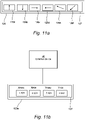
- Figs. 11a-b illustrates alternative embodiment of the adjustment means 120.
- the adjustment means 120 in this illustrative embodiment comprises digital adjustment means.
- the adjustment means 120 may comprise a display 127, such as for example touch sensitive display.
- the display 127 may be configured to display graphical objects 126a-f that are selectable by a user to modify the position of the different parts of the system 100.
- the adjustment means 120 may comprise one or more physical buttons. These buttons may be used to adjust the position of the different parts of the system 100.
- Fig. 11b shows an illustrative embodiment of an adjustment means 120.
- the control of the positioning system 100 is performed remotely, i.e. in another device.
- the adjustment means 120 in this illustrative embodiment is in communicative connection with an external device 40.
- the external device 40 may for example be a laptop computer, a personal computer, a work station, etc., or another kind of computer or computing device.
- the system 100 may be in operative communication with a processing unit.
- the processing unit may be arranged within the positioning system 100 or be part of a connected testing system.
- the processing unit may be configured to process the testing data generated by the positioning system 100.
- the processing unit may be configured to provide feedback to the user of the positioning system 100.
- the feedback may relate to how parts of the positioning system 100, such as for example the first portion 112 with the wireless power transmitter device 20, needs to be re-positioned. If a holding means for the wireless power transmitter device 20 is present, the inclination of the holding means may additionally need re-positioning.
- the feedback is transmitted to an external device of the user.
- the user may then manually, using the adjustment means 120 of the positioning system, alter the position of the different components of the system 100.
- the feedback is transmitted back to the positioning system 100 itself so that it automatically may adjust the position of the components needed re-positioning.
- the positioning system uses a minimum (or none) electrically conducting or magnetically active materials (such as metal, ferrites, magnets, iron, etc) as this can impact the behavior of the device being tested.
- the positioning system 100 described herein is at least in part constructed by a materials that do not interfere with the wireless power transfer; i.e. materials that have high electrical resistivity and a relative permeability ( ⁇ R ) very close to the value 1.0.
- a materials that do not interfere with the wireless power transfer i.e. materials that have high electrical resistivity and a relative permeability ( ⁇ R ) very close to the value 1.0.
- One example of such material may comprise thermosetting polymers or thermoplastics.
- the main body 110 is constructed by fiberglass (i.e. a fiber-reinforced plastic using glass fiber), Polyether Ether Ketone (PEEK), Polyoxymethylene (POM), or similar.
- the material may for example also be made of glass, wood or other non-magnetic material.
- the same material choices may be applied to other parts of the positioning system 100, such as the first and second portions 112, 118, position adjustment means 120a-c, attachment member 130, and/or the connecting means 114, 116.
- the main body 110, the first and second portions 112, 118, position adjustment means 120a-c, attachment member 130, and/or the connecting means 114, 116 may be produced by injection molding.
- At least some parts of the housing are made of plastic or another material suitable for admitting inductive coupling between the wireless power transmitter coil(s) 24 of the wireless power transmitter device 20 and the wireless power receiver coil(s) 14 of the wireless power receiver device 10.
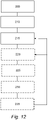
- Fig. 12 illustrates a method for positioning a wireless power transmitter device and/or a wireless power receiver device for testing of wireless power equipment.
- the method comprises a step of providing 205 a first portion 112 arranged to receive at least one wireless power transmitter device 20. It further comprises a step of providing 210 a second portion 118 comprising a movable attachment member 130 arranged to receive one wireless power receiver device 10.
- the method further comprises controlling 215 or causing a rotation of the attachment member 130 between a first end position and a second end position.
- the method may further comprise controlling 220 or causing a movement of the first portion 112 and/or the second portion 118.
- the method may further comprise controlling or adjusting 225 the holding means between a flat and an inclined position.
- the method may further comprise providing 230 feedback of the positioning system 100 relating to re-positioning of the first portion 112, the second portion 118 and/or the attachment member 130.
- the method further comprises causing re-positioning 235 of the first portion 112, the second portion 118 and/or the attachment member 130 based on feedback of the positioning system 100
Landscapes
- Engineering & Computer Science (AREA)
- Computer Networks & Wireless Communication (AREA)
- Power Engineering (AREA)
- Signal Processing (AREA)
- Physics & Mathematics (AREA)
- General Physics & Mathematics (AREA)
- Charge And Discharge Circuits For Batteries Or The Like (AREA)
Abstract
Description
- The present invention generally relates to the field of wireless power transfer, and more specifically to testing of wireless power equipment using a positioning system. Even more specifically, the present invention relates to a positioning system for testing of wireless power equipment in the form of a wireless power transmitter device and/or a wireless power receiver device. The present invention also relates to an associated method.
- Wireless power transfer is expected to become increasingly popular, for instance for wireless battery charging of mobile devices such as, for instance, mobile terminals, tablet computers, laptop computers, cameras, audio players, rechargeable toothbrushes, smart watches, wireless headsets, as well as various other consumer products and appliances.
- The Wireless Power Consortium has developed a wireless power transfer standard known as Qi. Other known wireless power transfer approaches include Alliance for Wireless Power, and Power Matters Alliance.
- The wireless power transfer standard known as Qi by the Wireless Power Consortium is one wireless power transfer manner. Operation of devices that comply with Qi relies on magnetic induction between planar coils. Two kinds of devices are involved, namely devices that provide wireless power (referred to as base stations or wireless power transmitter devices), and devices that consume wireless power (referred to as mobile devices). Power transfer takes place from a base station to a mobile device. For this purpose, a base station contains a subsystem (a power transmitter) that comprises a primary coil, whereas a mobile device contains a subsystem (a power receiver) that comprises a secondary coil. In operation, the primary coil and the secondary coil will constitute the two halves of a coreless resonant transformer. Typically, a base station has a flat surface, on top of which a user can place one or more mobile devices so as to enjoy wireless battery charging or operational power supply for the mobile device(s) placed on the base station.
- There is a need among different interest groups to test, measure or evaluate the behavior of the base station and/or the power receiver (mobile device) when performing wireless power transfer. Such interest groups may for instance involve any of the following: developers, manufacturers or suppliers of mobile devices; developers, manufacturers or suppliers of wireless power transmitter devices; test or compliance entities in the field of wireless power transfer; and test or compliance entities in the field of consumer product safety.
- It is an object of the invention to offer improvements in the technical field of testing, verifying, evaluating, researching and designing (henceforth referred to as 'testing') wireless power equipment.
- In a first aspect, a positioning system for testing of wireless power equipment in the form of a wireless power transmitter device and/or a wireless power receiver device is provided. The positioning system comprises a main body comprising a first portion arranged to receive at least one wireless power transmitter device, a second portion comprising a movable attachment member arranged to receive one wireless power receiver device, wherein the attachment member comprises rotating means configured to provide a rotation of the movable attachment member, and at least one position adjusting means arranged to control the rotation of the attachment member between a first end position and a second end position.
- In one embodiment, the rotating means comprises restriction means configured to restrict the rotation of the attachment member.
- The first portion may be arranged to be movable along the y-axis, and wherein the second may be arranged to be movable along the x-axis. The movable attachment member may be arranged to be rotatable around its axis.
- In one embodiment, in the first end position the attachment member is arranged such that the wireless power receiver device is arranged at distance from the wireless power transmitter device.
- In one embodiment, in the second end position the attachment member is arranged such that the wireless power receiver device is arranged adjacent to the wireless power transmitter device. The wireless power receiver device may be arranged in contact with the wireless power transmitter device in the second end position.
- In one embodiment, the at least one wireless power transmitter device is arranged on a holding means, wherein the holding means is configured to be adjustable between a flat and an inclined position.
- The positioning system may be in operative communication with a processing unit. The processing unit may be configured to provide feedback to the user of the positioning system relating to re-positioning of the first portion, the second portion and/or the attachment member.
- In one embodiment, the processing unit is configured to provide feedback to the positioning system and to instruct re-positioning of the first movable portion, the second movable portion and/or the attachment member. The feedback may be generated based on test data.
- In a second aspect a method for positioning a wireless power transmitter device and/or a wireless power receiver device for testing of wireless power equipment is provided. The method comprises providing a first portion arranged to receive at least one wireless power transmitter device, providing a second portion comprising a movable attachment member arranged to receive one wireless power receiver device, wherein the attachment member comprises rotating means configured to provide a rotation of the movable attachment member, and controlling the rotation of the attachment member between a first end position and a second end position.
- Objects, features and advantages of embodiments of the invention will appear from the following detailed description, reference being made to the accompanying drawings.
-
Fig. 1 is a schematic block diagram of a wireless power transmitter device for wireless power transfer to a wireless power receiver device. -
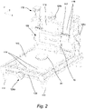
Fig. 2 is an isometric view of a positioning system according to one embodiment being arranged in a first position. -
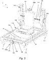
Fig. 3 is an isometric view of a positioning system according to one embodiment being arranged in a second position. -
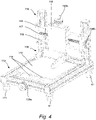
Fig. 4 is an isometric view of a positioning system according to a second embodiment being arranged in a second position. -
Fig. 5 is an isometric view of a positioning system according to a third embodiment being arranged in a first position. -
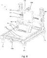
Fig. 6 is an isometric view of a positioning system according to a third embodiment being arranged in a second position. -
Fig. 7 is a schematic view of a wireless power receiver device according to one embodiment. -
Fig. 8 is an isometric view of an attachment member in a positioning system according to one embodiment. -
Figs. 9a-b are schematic top views of a part of a positioning system according to one embodiment. -
Figs. 10a-b are schematic top views of a part of a positioning system according to different embodiments. -
Figs. 11a-b are schematic views of a part of a positioning system according to different embodiments. -
Fig. 12 is an illustrative view of a method according to one embodiment. - Embodiments of the invention will now be described with reference to the accompanying drawings. The invention may, however, be embodied in many different forms and should not be construed as limited to the embodiments set forth herein; rather, these embodiments are provided so that this disclosure will be thorough and complete, and will fully convey the scope of the invention to those skilled in the art. The terminology used in the detailed description of the particular embodiments illustrated in the accompanying drawings is not intended to be limiting of the invention. In the drawings, like numbers refer to like elements.
-
Fig. 1 illustrates a wirelesspower transmitter device 20 for wireless power transfer to a wirelesspower receiver device 10. The wirelesspower receiver device 10 may, for instance, be a mobile device like a mobile terminal (e.g. smartphone) 10a,tablet computer 10b,laptop computer 10c, camera, audio player, rechargeable toothbrush, wireless headset, or another kind of consumer, military or medical product or appliance. - The wireless power transfer will be described as being compliant with the Qi standard by the Wireless Power Consortium; hence, the wireless
power transmitter device 20 is a base station in the Qi terminology. However, as already mentioned, the invention is generally applicable also to other wireless power transfer standards or approaches, including but not limited to the ones previously mentioned. - The wireless
power transmitter device 20 comprises awireless power transmitter 22 having at least one wirelesspower transmitter coil 24. Correspondingly, the wirelesspower receiver device 10 comprises awireless power receiver 12 having a wirelesspower receiver coil 14. In operation, the wirelesspower transmitter device 20 will transfer power wirelessly to the wirelesspower receiver device 10 by way ofmagnetic induction 18 via the wirelesspower transmitter coil 24 and wirelesspower receiver coil 14. - The power received by the wireless
power receiver coil 14 will drive aload 16 in themobile device 10. Typically, theload 16 may be a rechargeable battery, such as a lithium ion battery; hence, the wirelesspower transmitter device 20 will act as a wireless power charger for the wirelesspower receiver device 10. In another scenario, theload 16 may be electronic circuitry in the mobile device, wherein the wirelesspower transmitter device 20 will act as a wireless power supply for the wirelesspower receiver device 10. - In order to test the wireless power equipment in a reproducible manner, a positioning system 100 is provided. The positioning system 100 is arranged for testing of wireless power equipment in the form of a wireless power transmitter device, such as
device 20 inFig. 1 , and/or a wireless power receiver device, such asdevice 10 inFig. 1 . The positioning system 100 is arranged to provide accurate position readings in two or three dimensions when testing wireless power equipment. By altering the position of the wirelesspower transmitter device 20 and/or the position of the wirelesspower receiver device 10 with a high precision, important information of the behavior of thedevices Figs. 2-11 . - As seen in
Figs. 2-6 , the positioning system 100 comprises a main body 110, comprising afirst portion 112 and asecond portion 118. In one embodiment, at least one wirelesspower transmitter device 20 is arrangeable at thefirst portion 112, and the at least one wirelesspower receiver device 10 is arrangeable at thesecond portion 118. In an alternative embodiment (not shown), at least one wirelesspower transmitter device 20 is arrangeable at thesecond portion 118, and the at least one wirelesspower receiver device 10 is arrangeable at thefirst portion 112. - In the embodiments shown in
Figs. 2-6 , thefirst portion 112 has an extension in the x-y-plane. Thefirst portion 112 is preferably in the shape of a plate extending along the x-y-direction. - It is preferred if the
first portion 112 is movable along at least one axis. In this way, the wirelesspower transmitter device 20 and the wirelesspower receiver device 10 are movably arranged in relation to each other. - In one embodiment, the movement of the
first portion 112 is in the horizontal plane. InFigs. 2-6 , the horizontal plane is defined by the x- and y- axis. In the embodiment shown inFigs. 2-6 , the movement of thefirst portion 112 is along the y-axis. However, it should be understood that the movement of thefirst portion 112 additionally or alternatively could be along the x-axis. This is shown and described more in detail with reference toFigs. 10a-b . - As previously described, the
first portion 112 is preferably arranged with at least one wirelesspower transmitter device 20. The wirelesspower transmitter device 20 is preferably arranged in the center of thefirst portion 112, as shown inFig. 2 . However, as should be understood by a person skilled in the art the wirelesspower transmitter device 20 could be arranged on other parts of thefirst portion 112. The wirelesspower transmitter device 20 could be arranged on top of the surface of thefirst portion 112, as shown inFig. 2 , or being arranged in a recess (not shown) of thefirst portion 112. - In order to test different wireless
power transmitter device 20, it is preferred if the wirelesspower transmitter device 20 is removably arranged on thefirst portion 112. The wirelesspower transmitter device 20 may for example be attached to thefirst portion 112 using an adhesive or other fastening means. In one embodiment the wirelesspower transmitter device 20 is attached to thefirst portion 112 using one or more clamps. Additionally or alternatively, the wirelesspower transmitter device 20 is attached to thefirst portion 112 using one or more straps. - In one embodiment, the wireless
power transmitter device 20 is arranged on a holding means (not shown). The holding means can be adjusted between a flat and an inclined position, so as to alter the inclination of the wirelesspower transmitter device 20. - The wireless
power transmitter device 20 is preferably identical or similar to the wirelesspower transmitter device 20 described in relation toFig. 1 . The wirelesspower transmitter device 20 may have onetransmitter coil 24 or a plurality of transmitter coils. If thetransmitter device 20 has a plurality of transmitter coils, these may be arranged in a spaced apart arrangement and/or in a partly overlapping manner. In one embodiment, a plurality of transmitter coils is arranged in a partly overlapping manner on the same, or mainly the same, horizontal axis so that the majority of the surface of thetransmitter device 20 is arranged close to at least one transmitter coil. - In an alternative embodiment, four transmitter coils are arranged in a formation similar to a two times two matrix. In this embodiment, two of the transmitter coils are overlapping each other while some of the transmitter coils are arranged in a space apart arrangement from each other.
- In yet one embodiment, a plurality of transmitter coils are arranged in a circular pattern by having a central transmitter coil that is arranged in the centre of the
transmitter device 20 and a plurality of transmitter coils are arranged in a partly overlapping way around the central coil. In this configuration, the transmitter coils will act as if the coil was hexagonally shaped. - In one embodiment, as seen in
Figs. 2-3 , the wirelesspower transmitter device 20 has with a flat surface, hence a surface without any inclination. The wirelesspower transmitter device 20 may be arranged in a holding means, as previously described, or directly on thefirst portion 112. The surface of the wirelesspower transmitter device 20 resembles charging a wirelesspower receiver device 10 on a flat surface. -
Fig. 4 shows an embodiment of the positioning system 100 where the wirelesspower transmitter device 20 has been removed from the surface of thefirst portion 112. - In one alternative embodiment, as seen in
Figs. 5-6 , the wirelesspower transmitter device 20 has an inclined surface, where the inclination is in relation to the extension of thefirst portion 112. The wirelesspower transmitter device 20 may be arranged in a holding means, as previously described, or directly on thefirst portion 112. The surface of the wirelesspower transmitter device 20 resembles charging the wirelesspower receiver device 10 on an inclined surface. This may be the case with a wirelesspower transmitter device 20 having a tilted surface. A charger with a tilted surface allows the user to look at the screen of the device once the devices is charged in the charger. - The wireless
power receiver device 10 is schematically illustrated inFig. 7 . The wirelesspower receiver device 10 comprises at least oneload 16 and at least one wirelesspower receiver coil 14. In this illustrative example, the wirelesspower receiver device 10 has essentially the shape of a thin box with rounded edges and corners. In one embodiment the wirelesspower receiver device 10 is a testing device that for example emulates a mobile device. In an alternative embodiment, the wirelesspower receiver device 10 is an end user device, such as a consumer device, that has a testing mode. Hence, the wirelesspower receiver device 10 could be a mobile device such as for instance, a mobile terminal (e.g. smartphone), tablet computer (e.g. surfpad), laptop computer or another kind of consumer product or appliance being configured with a testing mode. - The wireless
power receiver device 10 has ahousing 11 having abottom side 11a adapted for placement on a surface of the wirelesspower transmitter device 20. Moreover, the housing comprises afront surface 11b (shown inFig. 9a ) being arranged opposite to the bottom surface. Thehousing 11 further has twoside surfaces 11c being arranged between thebottom surface 11a and thefront surface 11b, and opposite each other. Additionally, thehousing 11 comprises atop side surface 11e and abottom side surface 11f, being arranged opposite each other. The twoside surfaces 11c have a length that is longer than thetop side surface 11e and thebottom side surface 11f, so as to get the substantially rectangular shape. - As seen in
Figs. 2-6 , thefirst portion 112 is arranged in afirst sub-structure 113. Thefirst sub-structure 113 may be seen as a frame-like structure. The frame-like structure 113 may have a rectangular shape or any other form. Thefirst portion 112 is arranged in the frame-like structure 113. Thefirst portion 112 is preferably movably arranged in thesub-structure 113. - The movement of the
first portion 112 may be realized by connectingmeans 114 that allows thefirst portion 112 to move in thesub-structure 113. In one embodiment the connecting means 114 are realized as a plurality of connecting rods. However, it should be realized that thefirst portion 112 could be movably arranged in other ways as well. In the specific embodiments ofFigs. 2-6 , each connecting means 114 comprises three rods that extends in the movement direction of thefirst portion 112. The movement of thefirst portion 112 is controlled using position adjustment means 120a-c, which soon will be described more in detail. - The main body 110 may further comprise a plurality of
feet 111. In the embodiments shown inFigs. 2-6 , four feet are arranged on the bottom side of the frame-like structure 113. Thefeet 111 are preferably arranged on the side of the frame-structure 113 that is to be placed on a surface such as a table, being opposite the side that is arranged with thefirst portion 112. Although fourfeet 111 are illustrated, any number of feet that provides sufficient support to the system 100 may be possible. - In the embodiments shown in
Figs. 2-6 , thesecond portion 118 can be seen as being in the shape of a plate extending along the z-x-direction. In one embodiment, thesecond portion 118 is movable at least along the vertical axis, being the z-axis inFigs. 2-6 . - The
second portion 118 is arranged in asecond sub-structure 115. Thesecond sub-structure 115 comprises a plurality of connectingmeans 116 that allows thesecond portion 118 to move. In the embodiments shown inFigs. 2-6 , the connecting means 116 are realized as a plurality of connecting rods. However, it should be realized that thesecond portion 118 could be movably arranged in other ways as well. In the specific embodiments ofFigs. 2-6 , each connecting means 116 comprises two rods that extends in the movement direction of thesecond portion 118. - The
second portion 118 comprises anattachment member 130. Theattachment member 130 preferably extends out from thesecond portion 118, for example in the x-y-plane. Theattachment member 130 is arranged to receive a wirelesspower receiver device 10. The wirelesspower receiver device 10 is preferably removably attached to theattachment member 130 so as to allow testing ofdifferent devices 10. - The
attachment member 130 for holding the wirelesspower receiver device 10 is shown in more detail inFig. 8 . Theattachment member 130 shown inFig. 8 is adapted to accommodate a wirelesspower receiver device 10 having the shape similar to that described in relation toFig. 7 . As would be understood by a person skilled in the art, the shape and dimensions of theattachment member 130 will reflect the shape of the wirelesspower receiver device 10 that it is configured to hold. - In the embodiment shown in
Fig. 8 , theattachment member 130 comprises aback portion 131 and twoside portions power receiver device 10 is accommodated therein, thetop side surface 11e is facing one of theside portions bottom side surface 11f is facing theother side portions back portion 131. - At least one of the
side portions 132 comprisesgripping means 134. The gripping means 134 may for example be a recess arranged to receive the width of the wirelesspower receiver device 10. Additionally or alternatively, the gripping means 134 is the clamping force created when thedevice 10 is placed in theattachment member 130. - The
attachment member 130 further comprisesrotating means 136. The rotating means 136 are arranged to move, or rotate, the wirelesspower receiver device 10 arranged therein. In this way, different positions of the wirelesspower receiver device 10 can be achieved so as to allow for testing the behavior of the wirelesspower receiver device 10 and/or the wirelesspower transmitter device 20 at different orientations. The rotation serves two purposes, i.e. a) to facilitate testing a wirelesspower transmitter device 20 that has a titled charging surface, and b) to provide an easy and controlled method to move the wirelesspower receiver device 10 into the operating area of the wirelesspower transmitter device 20. As an example, a lever could be connected to the rotating means 136 to facilitate moving thepower receiver device 10 into testing position in a controlled manner. The rotating means 136 can comprise specific settings that limit or restrict the movement of rotation for the purpose of repeatability or consistency as well as to adapt the positioning system to variations on both thepower receiver device 10 as well as thepower transmitter device 20. - The
attachment member 130 further comprises restriction means configured to restrict the rotation of the attachment member. - The
attachment member 130 can be arranged in different positions, so as to allow different measurement positions of the wirelesspower receiver device 10. Theattachment member 130 can be moved between a first and a second end positions and a plurality of positions there between. In one embodiment themovable attachment member 130 is arranged to be rotatable around itsback portion 131. Theback portions 131 substantially parallel to the x-axis. The rotation could also be seen as a movement in the zy-plane. The embodiment shown inFigs. 2-3 and the embodiment shown inFigs. 5-6 will now be discussed together. - In
Figs. 2 and5 , theattachment member 130 is arranged in a first end position. In the first end position theattachment member 130 is arranged such that the wirelesspower receiver device 10 being arranged therein is arranged at a distance from the wirelesspower transmitter device 20 of thefirst portion 112. In this example, the wirelesspower receiver device 10 and the wirelesspower transmitter device 20 is arranged with an angular offset of approximately 90 degrees, so as to minimize any electromagnetic coupling between the two devices. - In
Figs. 3 and6 , theattachment member 130 is arranged in a second end position. In the second end position, theattachment member 130 is arranged such that the wirelesspower receiver device 10 being arranged therein is arranged adjacent to the wirelesspower transmitter device 20 of thefirst portion 112. Hence, there is no distance between the wirelesspower receiver device 10 and the wirelesspower transmitter device 20, and the wirelesspower receiver device 10 can be seen as lying on top of the wirelesspower transmitter device 20. - The first and second end positions achieved by the
attachment member 130 are further illustrated inFigs. 9a-b . Typically, the rotating means 136 fromFig 8 is used to transition from the first to the second end position. InFig. 9a , a top view is shown illustrating the location of the wirelesspower receiver device 10 in relation to the wirelesspower transmitter device 20 when theattachment member 130 is arranged in a first end position. Depending on the position of thefirst portion 112, the distance d1 between the center point of the wirelesspower transmitter device 20 and the center point of the wirelesspower receiver device 10 may vary. Here thebottom side 11a of thehousing 11 is facing the side of the wirelesspower transmitter device 20. Theside surface 11c of thehousing 11 is facing up in the same direction as the wirelesspower transmitter device 20 is facing. - In
Fig. 9b , a top view is shown illustrating the location of the wirelesspower receiver device 10 in relation to the wirelesspower transmitter device 20 when theattachment member 130 is arranged in a second end position. Depending on the position of thefirst portion 112, the distance between the center point of the wirelesspower transmitter device 20 and the center point of the wirelesspower receiver device 10 may vary. Here thebottom side 11a of thehousing 11 is facing the top surface of the wirelesspower transmitter device 20. - Turning back to
Figs. 2-6 , the position adjustment means 120a-c will now be described more in detail. The movement of thefirst portion 112, thesecond portion 118 and/or theattachment member 130 is controlled using position adjustment means 120a-c. The position adjustment means 120a-c is such that it allows for accurate small movements of thefirst portion 112, thesecond portion 118 and/or theattachment member 130. The position adjustment means 120a-c may be purely mechanical, purely electronic or a mixture of both. - In one embodiment, as shown in
Figs. 2-6 , the position adjustment means 120a-c comprises apositioning wheel 121 having a plurality ofsmall teeth 123. Theteeth 123 of thepositioning wheel 121 is preferably arranged along the whole circumference of thewheel 121, such that an external drive mechanism could be used to adjust the positioning. This drive mechanism could be automated or manually controlled. Thewheel 121 may be seen as a circular gear (such as a pinion). Thepositioning wheel 121 preferably has aknob 122 so as to allow the user to adjust the position in small incremental steps. - The position adjustment means 120c is arranged to adjust the movement of the
second portion 118. By rotating thepositioning wheel 120c, aspindle 117 will start to rotate. The rotation of thespindle 117 moves thesecond portion 118 along the axis of thespindle 117. - The
first portion 112 is controlled in a similar manner, using apositioning wheel 120a which cases a rotation of thespindle 124, which in turn causes a movement of thefirst portion 112. - The use of a spindle is also true for the movement of the
attachment member 130. - In an alternative embodiment (not shown) the positioning wheel is arranged to a toothed bar or rod i which the positioning wheel is arranged. The toothed bar arranged on one of the sides of the frame-
like structure 113. - The positioning wheel is connected to the connecting means 114 in a way so as to provide movement of the
first portion 112 by altering the position of thepositioning wheel 121. -
Figs. 10a-b shows two alternative embodiments of a positioning system, showing schematic top views of thefirst portion 112 being arranged in a frame-like structure 113. - In addition to the changes of position described this far, the positioning system could also be equipped with means to achieve changes in orientation through rotation. This can be achieved by rotating the
portion 112 around its axis in the same plane as theportion 112, and similarly rotate theportion 118 around its axis in the same plane asportion 118. Including these rotations would result in the positioning system 100 being able to move thewireless power devices - In
Fig. 10a , thefirst portion 112 is configured to be movable in both directions of the plane, i.e. both along the x-axis and the y-axis. In this embodiment, thefirst sub-structure 113 comprises two position adjustment means 120a-b. Here, the first position adjustment means 120a is arranged to control the movement along the y-axis and the second position adjustment means 120b is arranged to control the movement along the x-axis. The position adjustment means are described further in relation toFigs. 9a-b . - In this embodiment one wireless
power transmitter device 20, having onepower transmitter coil 24, is arranged on thefirst portion 112. In this embodiment, thepower transmitter coil 24 of the wirelesspower transmitter device 20 is illustrated as having the shape of a circle, although it should be understood that the wirelesspower transmitter device 20 could have any suitable shape such as a square, hexagon and the like. -
Fig. 10b shows an embodiment where thefirst portion 112 is configured to be movable in only one directions of the plane, i.e. only along the y-axis. In this embodiment, thefirst sub-structure 113 comprises one position adjustment means 120a. Here, the position adjustment means 120a is arranged to control the movement along the y-axis. - In this embodiment one wireless
power transmitter device 20, comprising four power transmitter coils 24(a-d), are arranged on thefirst portion 112. In this embodiment, the wirelesspower transmitter device 20 is illustrated as having the shape of a square, although it should be understood that the wirelesspower transmitter device 20 could have any suitable shape. Moreover, in this illustration, four wireless power transmitter coils 24a-d are disclosed on thefirst portion 112, however any reasonable number of wireless power transmitter coils 24 could be used. Additionally, any reasonable number of wirelesspower transmitter devices 20 could be arranged on thefirst portion 112. -
Figs. 11a-b illustrates alternative embodiment of the adjustment means 120. InFig. 11a , the adjustment means 120 in this illustrative embodiment comprises digital adjustment means. The adjustment means 120 may comprise adisplay 127, such as for example touch sensitive display. Thedisplay 127 may be configured to displaygraphical objects 126a-f that are selectable by a user to modify the position of the different parts of the system 100. Additionally, or alternatively, the adjustment means 120 may comprise one or more physical buttons. These buttons may be used to adjust the position of the different parts of the system 100. -
Fig. 11b shows an illustrative embodiment of an adjustment means 120. In this embodiment, the control of the positioning system 100 is performed remotely, i.e. in another device. Hence, the adjustment means 120 in this illustrative embodiment is in communicative connection with anexternal device 40. Theexternal device 40 may for example be a laptop computer, a personal computer, a work station, etc., or another kind of computer or computing device. - Additionally or alternatively to having an
external device 40, the system 100 may be in operative communication with a processing unit. The processing unit may be arranged within the positioning system 100 or be part of a connected testing system. The processing unit may be configured to process the testing data generated by the positioning system 100. The processing unit may be configured to provide feedback to the user of the positioning system 100. The feedback may relate to how parts of the positioning system 100, such as for example thefirst portion 112 with the wirelesspower transmitter device 20, needs to be re-positioned. If a holding means for the wirelesspower transmitter device 20 is present, the inclination of the holding means may additionally need re-positioning. - In one embodiment the feedback is transmitted to an external device of the user. The user may then manually, using the adjustment means 120 of the positioning system, alter the position of the different components of the system 100. Additionally, or alternatively, in one embodiment the feedback is transmitted back to the positioning system 100 itself so that it automatically may adjust the position of the components needed re-positioning.
- In the field of wireless power testing it is important that the positioning system uses a minimum (or none) electrically conducting or magnetically active materials (such as metal, ferrites, magnets, iron, etc) as this can impact the behavior of the device being tested.
- The positioning system 100 described herein is at least in part constructed by a materials that do not interfere with the wireless power transfer; i.e. materials that have high electrical resistivity and a relative permeability (µR) very close to the value 1.0. One example of such material may comprise thermosetting polymers or thermoplastics. In one embodiment the main body 110 is constructed by fiberglass (i.e. a fiber-reinforced plastic using glass fiber), Polyether Ether Ketone (PEEK), Polyoxymethylene (POM), or similar. The material may for example also be made of glass, wood or other non-magnetic material. The same material choices may be applied to other parts of the positioning system 100, such as the first and
second portions attachment member 130, and/or the connecting means 114, 116. - The main body 110, the first and
second portions attachment member 130, and/or the connecting means 114, 116 may be produced by injection molding. - At least some parts of the housing are made of plastic or another material suitable for admitting inductive coupling between the wireless power transmitter coil(s) 24 of the wireless
power transmitter device 20 and the wireless power receiver coil(s) 14 of the wirelesspower receiver device 10. -
Fig. 12 illustrates a method for positioning a wireless power transmitter device and/or a wireless power receiver device for testing of wireless power equipment. The method comprises a step of providing 205 afirst portion 112 arranged to receive at least one wirelesspower transmitter device 20. It further comprises a step of providing 210 asecond portion 118 comprising amovable attachment member 130 arranged to receive one wirelesspower receiver device 10. The method further comprises controlling 215 or causing a rotation of theattachment member 130 between a first end position and a second end position. The method may further comprise controlling 220 or causing a movement of thefirst portion 112 and/or thesecond portion 118. - The method may further comprise controlling or adjusting 225 the holding means between a flat and an inclined position.
- The method may further comprise providing 230 feedback of the positioning system 100 relating to re-positioning of the
first portion 112, thesecond portion 118 and/or theattachment member 130. - In one embodiment the method further comprises causing re-positioning 235 of the
first portion 112, thesecond portion 118 and/or theattachment member 130 based on feedback of the positioning system 100 - The invention has been described above in detail with reference to embodiments thereof. However, as is readily understood by those skilled in the art, other embodiments are equally possible within the scope of the present invention, as defined by the appended claims.
Claims (14)
- A positioning system (100) for testing of wireless power equipment in the form of a wireless power transmitter device (20) and/or a wireless power receiver device (10), the positioning system (100) comprising a main body (110) comprising:a first portion (112) arranged to receive at least one wireless power transmitter device (20),a second portion (118) comprising a movable attachment member (130) arranged to receive one wireless power receiver device (10), wherein the attachment member (130) comprises rotating means (136) configured to provide a rotation of the movable attachment member (130), andat least one position adjusting means (120) arranged to control the rotation of the attachment member (130) between a first end position and a second end position.
- The positioning system (100) as defined in claim 1, wherein the rotating means (136) comprises restriction means configured to restrict the rotation of the attachment member.
- The positioning system (100) as defined in claim 1 or 2, wherein the first portion (112) is arranged to be movable along the y-axis, and wherein the second portion (118) is arranged to be movable along the x-axis.
- The positioning system (100) as defined in any preceding claims, wherein the movable attachment member (130) is arranged to be rotatable around its axis.
- The positioning system (100) as defined in any preceding claims, wherein in the first end position the attachment member (130) is arranged such that the wireless power receiver device (10) is arranged at distance from the wireless power transmitter device (20).
- The positioning system (100) as defined in any preceding claims, wherein in the second end position the attachment member (130) is arranged such that the wireless power receiver device (10) is arranged adjacent to the wireless power transmitter device (20).
- The positioning system (100) as defined in any preceding claim, wherein the at least one wireless power transmitter device (20) is arranged on a holding means, wherein the holding means is configured to be adjustable between a flat and an inclined position.
- The positioning system (100) as defined in any preceding claim, wherein the first portion (112), the second portion (118) and/or the movable attachment member (130) is made of a non-magnetic material.
- The positioning system (100) as defined in any preceding claim, wherein the positioning system (100) is in operative communication with a processing unit.
- The positioning system (100) as defined in claim 9, wherein the processing unit is configured to provide feedback to the user of the positioning system (100) relating to re-positioning of the first portion (112), the second portion (118) and/or the attachment member (130).
- The positioning system (100) as defined in claim 9 or 10, wherein the processing unit is configured to provide feedback to the positioning system (100) and to instruct re-positioning of the first movable portion (112), the second movable portion (118) and/or the attachment member (130).
- The positioning system (100) as defined in claim 10 or 11, wherein the feedback is generated based on test data.
- The testing device as defined in any preceding claim, wherein the wireless power transmitter device (20) is in the form of a wireless charger (20).
- A method for positioning a wireless power transmitter device (20) and/or a wireless power receiver device (10) for testing of wireless power equipment, the method comprising:providing (205) a first portion (112) arranged to receive at least one wireless power transmitter device (20),providing (210) a second portion (118) comprising a movable attachment member (130) arranged to receive one wireless power receiver device (10), wherein the attachment member (130) comprises rotating means (136) configured to provide a rotation of the movable attachment member (130), andcontrolling (215) the rotation of the attachment member (130) between a first end position and a second end position.
Priority Applications (4)
| Application Number | Priority Date | Filing Date | Title |
|---|---|---|---|
| EP21160778.3A EP4054085A1 (en) | 2021-03-04 | 2021-03-04 | A positioning system and method for testing of wireless power equipment |
| US18/264,277 US20240305143A1 (en) | 2021-03-04 | 2022-03-04 | A positioning system and method for testing of wireless power equipment |
| PCT/EP2022/055623 WO2022184919A1 (en) | 2021-03-04 | 2022-03-04 | A positioning system and method for testing of wireless power equipment |
| EP22713382.4A EP4302410A1 (en) | 2021-03-04 | 2022-03-04 | A positioning system and method for testing of wireless power equipment |
Applications Claiming Priority (1)
| Application Number | Priority Date | Filing Date | Title |
|---|---|---|---|
| EP21160778.3A EP4054085A1 (en) | 2021-03-04 | 2021-03-04 | A positioning system and method for testing of wireless power equipment |
Publications (1)
| Publication Number | Publication Date |
|---|---|
| EP4054085A1 true EP4054085A1 (en) | 2022-09-07 |
Family
ID=74859190
Family Applications (2)
| Application Number | Title | Priority Date | Filing Date |
|---|---|---|---|
| EP21160778.3A Withdrawn EP4054085A1 (en) | 2021-03-04 | 2021-03-04 | A positioning system and method for testing of wireless power equipment |
| EP22713382.4A Pending EP4302410A1 (en) | 2021-03-04 | 2022-03-04 | A positioning system and method for testing of wireless power equipment |
Family Applications After (1)
| Application Number | Title | Priority Date | Filing Date |
|---|---|---|---|
| EP22713382.4A Pending EP4302410A1 (en) | 2021-03-04 | 2022-03-04 | A positioning system and method for testing of wireless power equipment |
Country Status (3)
| Country | Link |
|---|---|
| US (1) | US20240305143A1 (en) |
| EP (2) | EP4054085A1 (en) |
| WO (1) | WO2022184919A1 (en) |
Citations (3)
| Publication number | Priority date | Publication date | Assignee | Title |
|---|---|---|---|---|
| US20150204928A1 (en) * | 2014-01-17 | 2015-07-23 | Honda Motor Co., Ltd. | Method and apparatus to align wireless charging coils |
| US10614694B1 (en) * | 2014-06-06 | 2020-04-07 | Steelcase Inc. | Powered furniture assembly |
| US20200300923A1 (en) * | 2017-12-13 | 2020-09-24 | Sichuan Energy Internet Research Institute, Tsinghua University | Automatic test system of wireless charging system |
-
2021
- 2021-03-04 EP EP21160778.3A patent/EP4054085A1/en not_active Withdrawn
-
2022
- 2022-03-04 WO PCT/EP2022/055623 patent/WO2022184919A1/en not_active Ceased
- 2022-03-04 US US18/264,277 patent/US20240305143A1/en active Pending
- 2022-03-04 EP EP22713382.4A patent/EP4302410A1/en active Pending
Patent Citations (3)
| Publication number | Priority date | Publication date | Assignee | Title |
|---|---|---|---|---|
| US20150204928A1 (en) * | 2014-01-17 | 2015-07-23 | Honda Motor Co., Ltd. | Method and apparatus to align wireless charging coils |
| US10614694B1 (en) * | 2014-06-06 | 2020-04-07 | Steelcase Inc. | Powered furniture assembly |
| US20200300923A1 (en) * | 2017-12-13 | 2020-09-24 | Sichuan Energy Internet Research Institute, Tsinghua University | Automatic test system of wireless charging system |
Also Published As
| Publication number | Publication date |
|---|---|
| US20240305143A1 (en) | 2024-09-12 |
| EP4302410A1 (en) | 2024-01-10 |
| WO2022184919A1 (en) | 2022-09-09 |
Similar Documents
| Publication | Publication Date | Title |
|---|---|---|
| US11476851B1 (en) | Magnetically sensed user interface devices | |
| JP5713874B2 (en) | Wireless charger, foreign object detection method | |
| US6985134B2 (en) | Computer input device | |
| US11956029B2 (en) | System and method for testing of wireless power equipment | |
| US11235455B2 (en) | Master and slave of robot tool changing system | |
| KR20170131994A (en) | Wireless charging device and charging method thereof | |
| CN210273564U (en) | wireless charging base | |
| EP4054085A1 (en) | A positioning system and method for testing of wireless power equipment | |
| US11050276B2 (en) | Wireless charging device | |
| US20230032749A1 (en) | Wireless charging device capable of supporting user terminal in various directions and at various angles | |
| US20140191711A1 (en) | Kinetically Chargeable Stylus Device | |
| JP7847118B2 (en) | Testing apparatus and related methods for testing wireless power devices | |
| CN112615439A (en) | Wireless charging base, positioning sleeve, device, system and electronic equipment | |
| US20120153939A1 (en) | Magnetic field measuring device | |
| TW201813247A (en) | Power transmitting antenna and power transmitting device applying the same | |
| KR102308197B1 (en) | Equipment for measuring electromagnetic properties | |
| WO2021237412A1 (en) | Wireless charger | |
| CN207344602U (en) | A kind of mechanical rocker arm | |
| EP4390636A1 (en) | Permanent magnet assemblies for passive accessories | |
| KR20120003589A (en) | Terminal connection device | |
| CN223461644U (en) | Terminal wireless charging near-field radiation detection equipment | |
| KR102690494B1 (en) | Wireless power transmission system for note-book | |
| US20250030255A1 (en) | Electronic device charger | |
| EP4089432A1 (en) | Methods and systems for providing a secondary reference for wireless power transfer measurements and for evaluating a wireless power measurement device | |
| CN218782346U (en) | A test device for electronic equipment |
Legal Events
| Date | Code | Title | Description |
|---|---|---|---|
| PUAI | Public reference made under article 153(3) epc to a published international application that has entered the european phase |
Free format text: ORIGINAL CODE: 0009012 |
|
| STAA | Information on the status of an ep patent application or granted ep patent |
Free format text: STATUS: THE APPLICATION HAS BEEN PUBLISHED |
|
| AK | Designated contracting states |
Kind code of ref document: A1 Designated state(s): AL AT BE BG CH CY CZ DE DK EE ES FI FR GB GR HR HU IE IS IT LI LT LU LV MC MK MT NL NO PL PT RO RS SE SI SK SM TR |
|
| STAA | Information on the status of an ep patent application or granted ep patent |
Free format text: STATUS: REQUEST FOR EXAMINATION WAS MADE |
|
| 17P | Request for examination filed |
Effective date: 20230307 |
|
| RBV | Designated contracting states (corrected) |
Designated state(s): AL AT BE BG CH CY CZ DE DK EE ES FI FR GB GR HR HU IE IS IT LI LT LU LV MC MK MT NL NO PL PT RO RS SE SI SK SM TR |
|
| STAA | Information on the status of an ep patent application or granted ep patent |
Free format text: STATUS: EXAMINATION IS IN PROGRESS |
|
| 17Q | First examination report despatched |
Effective date: 20250313 |
|
| STAA | Information on the status of an ep patent application or granted ep patent |
Free format text: STATUS: THE APPLICATION IS DEEMED TO BE WITHDRAWN |
|
| 18D | Application deemed to be withdrawn |
Effective date: 20250715 |