EP4053996A1 - Multi-band antenna and method for tuning multi-band antenna - Google Patents
Multi-band antenna and method for tuning multi-band antenna Download PDFInfo
- Publication number
- EP4053996A1 EP4053996A1 EP22158144.0A EP22158144A EP4053996A1 EP 4053996 A1 EP4053996 A1 EP 4053996A1 EP 22158144 A EP22158144 A EP 22158144A EP 4053996 A1 EP4053996 A1 EP 4053996A1
- Authority
- EP
- European Patent Office
- Prior art keywords
- metamaterial
- band
- frequency band
- radiating element
- adjusting element
- Prior art date
- Legal status (The legal status is an assumption and is not a legal conclusion. Google has not performed a legal analysis and makes no representation as to the accuracy of the status listed.)
- Granted
Links
Images




Classifications
-
- H—ELECTRICITY
- H01—ELECTRIC ELEMENTS
- H01Q—ANTENNAS, i.e. RADIO AERIALS
- H01Q1/00—Details of, or arrangements associated with, antennas
- H01Q1/52—Means for reducing coupling between antennas; Means for reducing coupling between an antenna and another structure
- H01Q1/521—Means for reducing coupling between antennas; Means for reducing coupling between an antenna and another structure reducing the coupling between adjacent antennas
-
- H—ELECTRICITY
- H01—ELECTRIC ELEMENTS
- H01Q—ANTENNAS, i.e. RADIO AERIALS
- H01Q1/00—Details of, or arrangements associated with, antennas
- H01Q1/52—Means for reducing coupling between antennas; Means for reducing coupling between an antenna and another structure
-
- H—ELECTRICITY
- H01—ELECTRIC ELEMENTS
- H01Q—ANTENNAS, i.e. RADIO AERIALS
- H01Q15/00—Devices for reflection, refraction, diffraction or polarisation of waves radiated from an antenna, e.g. quasi-optical devices
- H01Q15/0006—Devices acting selectively as reflecting surface, as diffracting or as refracting device, e.g. frequency filtering or angular spatial filtering devices
- H01Q15/0013—Devices acting selectively as reflecting surface, as diffracting or as refracting device, e.g. frequency filtering or angular spatial filtering devices said selective devices working as frequency-selective reflecting surfaces, e.g. FSS, dichroic plates, surfaces being partly transmissive and reflective
-
- H—ELECTRICITY
- H01—ELECTRIC ELEMENTS
- H01Q—ANTENNAS, i.e. RADIO AERIALS
- H01Q15/00—Devices for reflection, refraction, diffraction or polarisation of waves radiated from an antenna, e.g. quasi-optical devices
- H01Q15/0006—Devices acting selectively as reflecting surface, as diffracting or as refracting device, e.g. frequency filtering or angular spatial filtering devices
- H01Q15/0086—Devices acting selectively as reflecting surface, as diffracting or as refracting device, e.g. frequency filtering or angular spatial filtering devices said selective devices having materials with a synthesized negative refractive index, e.g. metamaterials or left-handed materials
-
- H—ELECTRICITY
- H01—ELECTRIC ELEMENTS
- H01Q—ANTENNAS, i.e. RADIO AERIALS
- H01Q19/00—Combinations of primary active antenna elements and units with secondary devices, e.g. with quasi-optical devices, for giving the antenna a desired directional characteristic
- H01Q19/10—Combinations of primary active antenna elements and units with secondary devices, e.g. with quasi-optical devices, for giving the antenna a desired directional characteristic using reflecting surfaces
-
- H—ELECTRICITY
- H01—ELECTRIC ELEMENTS
- H01Q—ANTENNAS, i.e. RADIO AERIALS
- H01Q21/00—Antenna arrays or systems
- H01Q21/06—Arrays of individually energised antenna units similarly polarised and spaced apart
-
- H—ELECTRICITY
- H01—ELECTRIC ELEMENTS
- H01Q—ANTENNAS, i.e. RADIO AERIALS
- H01Q21/00—Antenna arrays or systems
- H01Q21/06—Arrays of individually energised antenna units similarly polarised and spaced apart
- H01Q21/061—Two dimensional planar arrays
-
- H—ELECTRICITY
- H01—ELECTRIC ELEMENTS
- H01Q—ANTENNAS, i.e. RADIO AERIALS
- H01Q21/00—Antenna arrays or systems
- H01Q21/24—Combinations of antenna units polarised in different directions for transmitting or receiving circularly and elliptically polarised waves or waves linearly polarised in any direction
- H01Q21/26—Turnstile or like antennas comprising arrangements of three or more elongated elements disposed radially and symmetrically in a horizontal plane about a common centre
-
- H—ELECTRICITY
- H01—ELECTRIC ELEMENTS
- H01Q—ANTENNAS, i.e. RADIO AERIALS
- H01Q21/00—Antenna arrays or systems
- H01Q21/28—Combinations of substantially independent non-interacting antenna units or systems
-
- H—ELECTRICITY
- H01—ELECTRIC ELEMENTS
- H01Q—ANTENNAS, i.e. RADIO AERIALS
- H01Q5/00—Arrangements for simultaneous operation of antennas on two or more different wavebands, e.g. dual-band or multi-band arrangements
- H01Q5/30—Arrangements for providing operation on different wavebands
-
- H—ELECTRICITY
- H01—ELECTRIC ELEMENTS
- H01Q—ANTENNAS, i.e. RADIO AERIALS
- H01Q9/00—Electrically-short antennas having dimensions not more than twice the operating wavelength and consisting of conductive active radiating elements
- H01Q9/04—Resonant antennas
- H01Q9/16—Resonant antennas with feed intermediate between the extremities of the antenna, e.g. centre-fed dipole
- H01Q9/28—Conical, cylindrical, cage, strip, gauze, or like elements having an extended radiating surface; Elements comprising two conical surfaces having collinear axes and adjacent apices and fed by two-conductor transmission lines
-
- H—ELECTRICITY
- H01—ELECTRIC ELEMENTS
- H01Q—ANTENNAS, i.e. RADIO AERIALS
- H01Q9/00—Electrically-short antennas having dimensions not more than twice the operating wavelength and consisting of conductive active radiating elements
- H01Q9/04—Resonant antennas
- H01Q9/16—Resonant antennas with feed intermediate between the extremities of the antenna, e.g. centre-fed dipole
- H01Q9/28—Conical, cylindrical, cage, strip, gauze, or like elements having an extended radiating surface; Elements comprising two conical surfaces having collinear axes and adjacent apices and fed by two-conductor transmission lines
- H01Q9/285—Planar dipole
-
- H—ELECTRICITY
- H01—ELECTRIC ELEMENTS
- H01Q—ANTENNAS, i.e. RADIO AERIALS
- H01Q1/00—Details of, or arrangements associated with, antennas
- H01Q1/12—Supports; Mounting means
- H01Q1/22—Supports; Mounting means by structural association with other equipment or articles
- H01Q1/24—Supports; Mounting means by structural association with other equipment or articles with receiving set
- H01Q1/241—Supports; Mounting means by structural association with other equipment or articles with receiving set used in mobile communications, e.g. GSM
- H01Q1/246—Supports; Mounting means by structural association with other equipment or articles with receiving set used in mobile communications, e.g. GSM specially adapted for base stations
-
- H—ELECTRICITY
- H01—ELECTRIC ELEMENTS
- H01Q—ANTENNAS, i.e. RADIO AERIALS
- H01Q21/00—Antenna arrays or systems
- H01Q21/06—Arrays of individually energised antenna units similarly polarised and spaced apart
- H01Q21/061—Two dimensional planar arrays
- H01Q21/062—Two dimensional planar arrays using dipole aerials
-
- H—ELECTRICITY
- H01—ELECTRIC ELEMENTS
- H01Q—ANTENNAS, i.e. RADIO AERIALS
- H01Q21/00—Antenna arrays or systems
- H01Q21/24—Combinations of antenna units polarised in different directions for transmitting or receiving circularly and elliptically polarised waves or waves linearly polarised in any direction
-
- H—ELECTRICITY
- H01—ELECTRIC ELEMENTS
- H01Q—ANTENNAS, i.e. RADIO AERIALS
- H01Q5/00—Arrangements for simultaneous operation of antennas on two or more different wavebands, e.g. dual-band or multi-band arrangements
- H01Q5/40—Imbricated or interleaved structures; Combined or electromagnetically coupled arrangements, e.g. comprising two or more non-connected fed radiating elements
- H01Q5/48—Combinations of two or more dipole type antennas
Definitions
- the present disclosure relates to communication systems, and more specifically, to multi-band antennas and to methods for tuning multi-band antennas that are suitable for communication systems.
- a geographic area is divided into a series of regions that are referred to as "cells" which are served by respective base stations.
- the base station may include one or more base station antennas that are configured to provide two-way radio frequency (“RF”) communications with mobile subscribers that are within the cell served by the base station.
- RF radio frequency
- each base station is divided into "sectors".
- a hexagonally shaped cell is divided into three 120° sectors, and each sector is served by one or more base station antennas that generate radiation patterns or "antenna beams" having an azimuth Half Power Beam Width (HPBW) of approximately 65°.
- HPBW azimuth Half Power Beam Width
- the base station antennas are mounted on a tower structure, with the antenna beams that are generated by the base station antennas directed outwardly.
- Base station antennas are often realized as linear or planar phased arrays of radiating elements.
- One very common multi-band antenna includes one linear array of "low-band” radiating elements that are used to provide service in some or all of the 617 to 960 MHz frequency band, and two linear arrays of "mid-band” radiating elements that are used to provide service in some or all of the 1427 to 2690 MHz frequency band. These linear arrays of low-band and mid-band radiating elements are typically mounted in a side-by-side fashion.
- multi-band antennas may include two linear arrays of low-band radiating elements and two (or four) linear arrays of mid-band radiating elements. These antennas may be used in various applications, including 4x4 multiple-input and multiple-output (“MIMO") applications, or may be used as multi-band antennas with two different low-bands (for example, 700 MHz low-band linear array and 800 MHz low-band linear array) and two different mid-bands (for example, 1800 MHz mid-band linear array and 2100 MHz mid-band linear array).
- MIMO multiple-input and multiple-output
- the lateral spacing between the linear arrays may be reduced in order to keep the width of the base station antenna within acceptable dimensions.
- the degree of signal coupling between the linear arrays may increase.
- the coupling interference between the low-band radiating elements or between the mid-band radiating elements may increase; the low-band radiating element may produce large scattering effects on the mid-band radiating elements in the rear area.
- These "parasitic" couplings may cause distortion of the radiation pattern, for example, an undesired increase in HPBW.
- a multi-band antenna comprising: a first radiating element, configured to operate within a first frequency band and to emit first electromagnetic radiation within the first frequency band; a second radiating element, configured to operate within a second frequency band different from the first frequency band and to emit second electromagnetic radiation within the second frequency band; and a metamaterial adjusting element, configured to at least partially reflect the second electromagnetic radiation incident on the metamaterial adjusting element such that the reflected second electromagnetic radiation is redirected to at least partially cancel the interference of the first radiating element to the second radiating element.
- a multi-band antenna comprising: a first radiating element array, including a plurality of first radiating elements, the first radiating element array being configured to operate within a first frequency band and to generate a first antenna beam within the first frequency band; a second radiating element array, including a plurality of second radiating elements, the second radiating element array being configured to operate within a second frequency band and to generate a second antenna beam within the second frequency band; and a metamaterial adjusting element array, including a plurality of metamaterial adjusting elements for the plurality of second radiating elements, wherein the plurality of metamaterial adjusting elements are arranged around the second radiating element array and at least partially behind the first radiating element array, and each metamaterial adjusting element is configured to have frequency selective characteristics, so that the metamaterial adjusting element array is configured to adjust the radiation pattern of the second antenna beam.
- a multi-band antenna comprising: a first radiating element array, including a plurality of first radiating elements, the first radiating element array being configured to operate within a first frequency band and to generate a first antenna beam within the first frequency band; a second radiating element array, including a plurality of second radiating elements, the second radiating element array being configured to operate within a second frequency band and to generate a second antenna beam within the second frequency band; wherein each first radiating element includes a radiator including a first dipole arm and a second dipole arm, the first dipole arm and the second dipole arm each include a narrowed arm segment and a widened arm segment, and the narrowed arm segment and the widened arm segment form at least one resonant structure, the multi-band antenna further including: a metamaterial adjusting element array, including a plurality of metamaterial adjusting elements respectively for the plurality of second radiating elements, wherein the plurality of metamaterial adjusting elements and the reson
- a method for tuning a multi-band antenna including a reflector and a first radiating element array and a second radiating element array mounted on the reflector, the first radiating element array including a plurality of first radiating elements, the first radiating element array being configured to operate within a first frequency band and to generate a first antenna beam within the first frequency band; the second radiating element array including a plurality of second radiating elements, the second radiating element array being configured to operate within a second frequency band and to generate a second antenna beam within the second frequency band, wherein the method includes (1) arranging a metamaterial adjusting element around the second radiating element array and at least partially behind the first radiating element array and (2) adjusting the orientation and/or distance of the metamaterial adjusting element relative to the reflector, and/or adjusting the distance of the metamaterial adjusting element to the second radiating element array, so as to tune the pattern of the second antenna beam.
- a method for tuning a multi-band antenna including a reflector and a first radiating element array and a second radiating element array mounted on the reflector, the first radiating element array including a plurality of first radiating elements, the first radiating element array being configured to operate within a first frequency band and to generate a first antenna beam within the first frequency band; the second radiating element array including a plurality of second radiating elements, the second radiating element array being configured to operate within a second frequency band and to generate a second antenna beam within the second frequency band, wherein each first radiating element includes a radiator including a first dipole arm and a second dipole arm, the first dipole arm and the second dipole arm each include a narrowed arm segment and a widened arm segment, the narrowed arm segment and the widened arm segment form at least one resonant structure, and the resonant structure attenuates currents within a first portion of frequency range of the second frequency band
- a multi-band antenna comprising a reflector, a first radiating element that is configured to operate within a first frequency band, a second radiating element that is configured to operate within a second frequency band different from the first frequency band, and a metamaterial adjusting element mounted to extend forwardly from the reflector, the metamaterial adjusting element configured to substantially reflect electromagnetic radiation incident on the metamaterial adjusting element that is within a first portion of the second frequency band.
- an element when an element is said to be “on” another element, “attached” to another element, “connected” to another element, “coupled” to another element, or “in contact with” another element, etc., the element may be directly on another element, attached to another element, connected to another element, coupled to another element, or in contact with another element, or an intermediate element may be present.
- an element is described “directly” “on” another element, “directly attached” to another element, “directly connected” to another element, “directly coupled” to another element or “directly in contact with” another element, there will be no intermediate elements.
- one feature when one feature is arranged “adjacent” to another feature, it may mean that one feature has a part overlapping with the adjacent feature or a part located above or below the adjacent feature.
- connection means that one element/node/feature can be mechanically, electrically, logically or otherwise connected with another element/node/feature in a direct or indirect manner to allow interaction, even though the two features may not be directly connected. That is, "connected” means direct and indirect connection of components or other features, including connection using one or a plurality of intermediate components.
- spatial relationship terms such as “upper”, “lower”, “left”, “right”, “front”, “back”, “high” and “low” can explain the relationship between one feature and another in the drawings. It should be understood that, in addition to the orientations shown in the attached drawings, the terms expressing spatial relations also comprise different orientations of a device in use or operation. For example, when a device in the attached drawings rotates reversely, the features originally described as being “below” other features now can be described as being “above” the other features. The device may also be oriented by other means (rotated by 90 degrees or at other locations), and at this time, a relative spatial relation will be explained accordingly.
- a or B comprises “A and B” and “A or B”, not exclusively “A” or “B”, unless otherwise specified.
- the term "exemplary” means “serving as an example, instance or explanation", not as a “model” to be accurately copied. Any realization method described exemplarily herein may not be necessarily interpreted as being preferable or advantageous over other realization methods. Furthermore, the present disclosure is not limited by any expressed or implied theory given in the above technical field, background art, summary of the invention or specific embodiments.
- the word “basically” means including any minor changes caused by design or manufacturing defects, device or component tolerances, environmental influences, and/or other factors.
- the word “basically” also allows the gap from the perfect or ideal situation due to parasitic effects, noise, and other practical considerations that may be present in the actual realization.
- first”, “second” and similar terms may also be used herein, and thus are not intended to be limitative.
- the words “first”, “second” and other such numerical words involving structures or elements do not imply a sequence or order.
- An aspect of the present disclosure provides a multi-band antenna, which includes: a first radiating element, for example, a low-band radiating element, configured to be capable of operating within a first frequency band and emitting first electromagnetic radiation within the first frequency band; a second radiating element, for example, a mid-band radiating element, configured to be capable of operating within a second frequency band different from the first frequency band and emitting second electromagnetic radiation within the second frequency band; and a metamaterial adjusting element, configured to at least partially reflect the second electromagnetic radiation incident on the metamaterial adjusting element such that the reflected second electromagnetic radiation is redirected so as to at least partially cancel or offset the interference, for example, scattering effect, of the first radiating element to the second radiating element. Therefore, the multi-band antenna, according to the present disclosure, can improve the shape of the radiation
- the multi-band antenna will now be described in more detail with reference to the drawings. It should be noted that the multi-band antenna may also have other components, and in order to avoid obscuring the main points of the present disclosure, the other components are not shown in the attached drawings and will not be discussed herein. It should also be noted that the drawings only schematically show the relative positional relationship of various components, and there is no particular limitation on the specific structure of each component.
- Fig. 1 is a schematic perspective view of a multi-band antenna 100 according to some examples of the present disclosure
- Fig. 2a is a schematic front view of the multi-band antenna 100 in Fig. 1
- Fig. 2b is a schematic side view of the multi-band antenna 100 taken along the line A-A of Fig. 2a
- Fig. 2c is a schematic end view of the multi-band antenna 100 taken along the line B-B of Fig. 2a .
- the multi-band antenna 100 may be mounted for operation on a raised structure, such as an antenna tower, a telegraph pole, a building, a water tower, etc., such that a longitudinal axis of the antenna 100 extends roughly perpendicular to the ground.
- the antenna 100 usually includes a radome (not shown) that provides environmental protection.
- the multi-band antenna 100 includes a reflector 160, which may comprise a metal surface that provides a ground plane and reflects electromagnetic radiation reaching the metal surface such that the electromagnetic radiation is redirected to propagate, for example, forwardly.
- the antenna 100 may further include additional mechanical and electronic components, such as one or more of connectors, cables, phase shifters, remote electronic tilt (RET) units, duplexers, and the like, arranged on a rear side of the reflector 160.
- RET remote electronic tilt
- the multi-band antenna 100 may further include first radiating elements 110 and second radiating elements 120 that are arranged on a front side of the reflector 160.
- the first radiating elements 110 are arranged as two vertically extending linear arrays adjacent to each other in a horizontal direction.
- the second radiating elements 120 are likewise arranged as two vertically extending linear arrays adjacent to each other in the horizontal direction.
- the two linear arrays of second radiating elements 120 may be arranged between the two linear arrays of first radiating elements 110 to reduce the width of the antenna.
- An operating frequency band of the first radiating elements 110 may be, for example, 617 to 960 MHz or a sub-band thereof.
- An operating frequency band of the second radiating elements 120 may be, for example, 1427 to 2690 MHz or a sub-band thereof.
- the first radiating elements 110 may be configured as low-band radiating elements that can operate within a first frequency band, for example 617 to 960 MHz or a sub-band thereof, and emit first electromagnetic radiation within the first frequency band.
- the second radiating elements 120 may be configured as mid-band radiating elements that can operate within a second frequency band, for example 1427 to 2690 MHz or a sub-band thereof, and emit second electromagnetic radiation within the second frequency band.
- the two linear arrays may be configured to form two separate first antenna beams (per polarization) within the first frequency band, or may be configured to form a single antenna beam (per polarization) within the first frequency band.
- the two linear arrays may be configured to form two separate second antenna beams (per polarization) within the second frequency band, or may be configured to form a single first antenna beam (per polarization) within the second frequency band.
- the multi-band antenna 100 may further include a metamaterial adjusting element 140 arranged on the front side of the reflector 160 to cooperate with the second radiating element 120, thereby at least partially cancelling a negative effect, for example, distortion of the radiation pattern of the second antenna beam, caused by the interference, such as scattering effect, of the first radiating element 110 to the second radiating element 120.
- a metamaterial adjusting element 140 arranged on the front side of the reflector 160 to cooperate with the second radiating element 120, thereby at least partially cancelling a negative effect, for example, distortion of the radiation pattern of the second antenna beam, caused by the interference, such as scattering effect, of the first radiating element 110 to the second radiating element 120.
- the metamaterial adjusting element 140 should be understood as a structure constituted by metamaterials or including metamaterials for adjusting the radio frequency performance of the antenna.
- Metamaterials are man-made materials with special properties that allow electromagnetic waves to change the general properties of the metamaterials. The properties of metamaterials stem from their precise geometric structure and size.
- metamaterials should be understood broadly, that is, metamaterials can include all periodic electromagnetic materials, such as frequency selective surfaces, electromagnetic band gap structures, metasurfaces, artificial magnetic conductors, photonic band gap structures, surface plasmons, and the like.
- the metamaterial adjusting element 140 may be configured as a frequency selective surface.
- the frequency selective surface can filter electromagnetic waves in space.
- a metamaterial with a specific reflection/transmission phase distribution can be formed.
- the frequency selective surface can selectively pass or block electromagnetic waves of different frequencies.
- the frequency selective surface may be configured as a printed circuit board element, and the periodically arranged frequency selective surface units 1401 may be printed on the printed circuit board element.
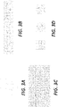
- Fig. 3a shows an exemplary frequency selective surface unit 1401.
- a column of frequency selective surface units 1401 may be printed on the printed circuit board element to form a one-dimensional period of the frequency selective surface units 1401, as shown in Fig. 3b .
- a plurality of rows and a plurality of columns of frequency selective surface units 1401 may be printed on the printed circuit board element to form a two-dimensional period of the frequency selective surface units 1401, as shown in Fig. 3c .
- the spacing between the frequency selective surface units 1401 may also be adjusted according to actual application scenarios.
- the resonant frequency point and/or operating bandwidth of the frequency selective surface may be adjusted by designing various sizes of the frequency selective surface unit 1401 to meet the requirements of different resonance points, multi-frequency resonance, and/or broadband resonance in different application scenarios.
- the frequency selective surface is designed as a cost-effective single-layer PCB element.
- the frequency selective surface may be designed as a multi-layer PCB element to realize wideband and ultra-wideband operating bandwidth.
- the frequency selective surface may also be constituted by periodically arranged metal patch units, which may be less expensive to fabricate than printed circuit board based frequency selective surfaces.
- the multi-band antenna 100 may include a plurality of metamaterial adjusting elements 140 for a plurality of second radiating elements 120, and these metamaterial adjusting elements 140 may be arranged as a metamaterial adjusting element 140 array around the linear arrays of second radiating elements 120 and behind the first radiating elements.
- the metamaterial adjusting elements 140 may, for example, be designed to reflect the second electromagnetic radiation incident thereon while passing the first electromagnetic radiation incident thereon.
- the metamaterial adjusting elements 140 can at least partially reflect the second electromagnetic radiation incident on the metamaterial adjusting elements 140 such that the reflected second electromagnetic radiation is redirected without substantially impacting the radiation patterns of the linear arrays of first radiating elements 110.
- the metamaterial adjusting elements 140 can at least partially cancel the scattering effect of the first radiating elements 110 on the second radiating elements 120 by multi-path transmission of the electromagnetic radiation.
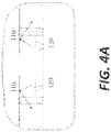
- Fig. 4a schematically shows a schematic diagram of the scattering effect of the first radiating element 110 on the second radiating element 120
- Fig. 4b schematically shows a schematic diagram of at least partially cancelling the scattering effect by the metamaterial adjusting element 140.
- the first radiating element 110 is in front of the second radiating element 120 and at least partially covers the second radiating element 120, and thus the electromagnetic radiation emitted forward by the second radiating element 120 is at least incident on a radiator of the first radiating element 110.
- a dipole arm of the radiator of the first radiating element 110 can be regarded as an LC resonance structure with a resonant frequency within the aforementioned first frequency band, and the LC resonance structure will inevitably introduce a secondary resonance, which may fall into the aforementioned second frequency band, for example, near 1950 MHz.
- the second radiating elements 120 during operation of the second radiating elements 120, a current within the second frequency band will be induced on the dipole arm of the first radiating element 110, thereby causing a scattering effect on the radiation emitted by the second radiating element 120.
- the second electromagnetic radiation emitted by one second radiating element 120 is incident on a radiator of one first radiating element 110 and is radiated backward by the radiator of the first radiating element 110 due to the scattering effect, thus changing the original radiation direction of a portion of the second electromagnetic radiation.
- the radiation pattern of the second antenna beam of the second radiating element 120 array may be distorted.
- the metamaterial adjusting elements 140 may be arranged on an outer peripheral side of the first radiating element 110 array and the second radiating element 120 array.
- the first metamaterial adjusting element 140 is arranged on the left side of the linear arrays of first radiating elements 110 and the linear arrays of second radiating elements 120
- the second metamaterial adjusting element 140 is arranged on the right side of the linear arrays of first radiating elements 110 and the linear arrays of second radiating elements 120.
- the metamaterial adjusting elements 140 With this arrangement of the metamaterial adjusting elements 140, the second electromagnetic radiation emitted by the second radiating element 120 that is scattered from the forward direction by the first radiating elements may be incident on the metamaterial adjusting elements 140 and be radiated forward by the metamaterial adjusting elements 140 (see the transmission paths indicated by the solid line). Therefore, the metamaterial adjusting element 140 realizes a multipath transmission of a portion of the second electromagnetic radiation to at least partially cancel the interference caused by the scattering effect.
- the metamaterial adjusting element 140 is arranged behind the first radiating element 110, it should also be considered that sidelobes and/or backlobes of the first antenna beam may be incident on the metamaterial adjusting element 140.
- the metamaterial adjusting element 140 may be configured as a spatial band-stop filter so that the first electromagnetic radiation within the first frequency band or a sub-band thereof can be transmitted through the metamaterial adjusting element 140, and the electromagnetic radiation within the second frequency band or a sub-band thereof is basically blocked, for example, reflected, by the metamaterial adjusting element 140. Therefore, the metamaterial adjusting element 140 can at least partially avoid the distortion of the radiation pattern of the second antenna beam caused by the scattering effect while reducing the negative effect on the radiation pattern of the first antenna beam.
- influencing factors need to be considered, such as: the number of the metamaterial adjusting elements 140, the orientation and/or distance of the metamaterial adjusting element 140 relative to the reflector (that is, an angle of an acting surface of the metamaterial adjusting element 140 toward the second radiating element 120 and/or a forward extending dimension of the acting surface of the metamaterial adjusting element 140), and the distance of the metamaterial adjusting element 140 to the second radiating element 120. Therefore, one or more of the aforementioned influencing factors may be adjusted appropriately according to the actual tuning situation to tune the pattern of the second antenna beam, so that the pattern of the second antenna beam meets desired requirements such as -3dB lobe width, - 10dB lobe width, and/or pattern shape, etc.
- the radiator of the first radiating element 110 may be designed as a cloaked radiator.
- the first radiating element 110 includes a radiator with a dipole arm that includes a narrowed arm segment 370 and a widened arm segment 380.
- the narrowed arm segment 370 and the widened arm segment 380 can form at least one resonance structure that is configured to at least partially attenuate currents within at least part of the frequency range of the second frequency band that could otherwise be induced on the dipole arm itself.
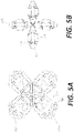
- Fig. 5a and Fig. 5b show two typical embodiments of the radiator of the first radiating element 110.
- a first radiator 1101 of the first radiating element 110 extends obliquely at +45°
- a second radiator 1102 of the first radiating element 110 extends obliquely at -45°
- the first radiator 1101 of the first radiating element 110 may extend horizontally (that is, at 0°)
- the second radiator 1102 of the first radiating element 110 may extend vertically (that is, at 90°).
- Each dipole arm of each radiator may include at least one narrowed arm segment 370 and at least one widened arm segment 380.
- Each arm may include two conductive paths, wherein a first conductive path forms half of the generally elongated dipole arm and a second conductive path forms the other half of the dipole arm.
- Each conductive path may include a metal pattern that has a widened arm segment 380 and a narrowed arm segment 370.
- the narrowed arm segment 370 may be configured as a meandered arm segment to increase the path length thereof, thereby facilitating the compactness of the first radiating element 110 and/or a desired filtering effect.
- the narrowed arm segment 370 may be realized as a non-linear conductive segment, and may act as a high impedance segment that interrupts currents in the second frequency band, that is, the mid-band, that could otherwise be induced on the dipole arm itself. As such, the narrowed arm segment 370 can reduce induced mid-band currents on the first radiating element 110, thereby further reducing the scattering effect of the first radiating element 110 on the second radiating element 120.
- the narrowed arm segment 370 may make the first radiating element 110 almost invisible to the second radiating element 120, and thus endows the first radiating element 110 with a cloaking function. It is advantageous for the first radiating element 110 to have a cloaking function because the less mid-band current induced on the dipole arm of the first radiating element 110, the smaller impact on the radiation pattern of the second radiating element 120 array.
- the aforementioned first radiating element 110 having a cloaking function can reduce the scattering effect, in some cases, the radiating element 110 may not be able to realize good cloaking function for the entire operating frequency band of the second radiating element 120. For example, it may be possible that the first radiating element 110 may produce undesired interference at one or more frequency point or sub-bands within the operating frequency band of the second radiating element 120.
- a suitable metamaterial adjusting element 140 In an actual tuning process, in order to design a suitable metamaterial adjusting element 140, the following steps of a method may be carried out. First, testing and analyzing the radiation pattern of the second antenna beam of the second radiating element 120 array at a plurality of frequency points within the second frequency band is performed. Then, it is determined whether the performance of the radiation pattern of the second antenna beam at the at least one frequency point needs to be improved according to design requirements; in other words, the first radiating element 110 may have a non-negligible scattering effect on the second radiating element 120 at the at least one frequency point, and the design requirements may be, for example, -3dB lobe width, -10dB lobe width, and/or pattern shape, etc. Last, a metamaterial adjusting element 140 is designed for the at least one frequency point such that the metamaterial adjusting element 140 shows reflection characteristics at the at least one frequency point.
- the metamaterial adjusting element 140 may be configured to at least reflect the second electromagnetic radiation incident on the metamaterial adjusting element 140 within a second portion of the frequency range of the second frequency band, wherein the superposition of the first portion of frequency range and the second portion of frequency range can cover the second frequency band.
- the metamaterial adjusting element 140 may be designed for the at least one frequency point such that the metamaterial adjusting element 140 is configured as a spatial band-stop filter, the stop band of which covers the at least one frequency point.
- the combination of the cloaking function of the first radiating element 110 and the frequency selective characteristics of the metamaterial adjusting element 140 can reduce the interference from the first radiating element 110 over a wider frequency band, for example, the entire operating frequency band of the second radiating element 120, thereby improving the radiation pattern of the second antenna beam of the second radiating element 120 array.
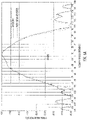
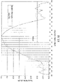
- Figs. 6a to 6c are azimuth patterns for a multi-band antenna with a metamaterial adjusting element and a multi-band antenna without a metamaterial adjusting element at 1.9 GHz, 1.95 GHz, and 2.0 GHz, respectively according to some examples of the present disclosure.
- the shape of the azimuth pattern of the multi-band antenna at the selected frequency points can be effectively improved by the metamaterial adjusting element.
- a schematic end view of the multi-band antenna 100 according to some examples of the present disclosure will be further introduced.
- the multi-band antenna 100' may include first radiating elements 110', second radiating elements 120', and third radiating elements 130' that are arranged on a front side of a reflector 160'.
- the second radiating elements 120' are arranged as two vertically extending linear arrays that are adjacent to each other in a horizontal direction.
- the two linear arrays of second radiating elements 120' may be configured to form two separate antenna beams, or may be configured to form a single antenna beam.
- the third radiating elements 130' may be arranged as a linear array that is disposed between the two linear arrays of second radiating elements 120'.
- the first radiating elements 110' are arranged staggered on both sides of a vertical central axis of the linear array of third radiating elements 130' slightly deviated from the axis, so as to obtain an antenna beam with a narrower beam width in the azimuth plane.
- An operating frequency band of the first radiating elements 110' may be, for example, 617 to 960 MHz or a sub-band thereof.
- An operating frequency band of the second radiating elements 120' may be, for example, 1427 to 2690 MHz or a sub-band thereof.
- An operating frequency band of the third radiating elements 130' may be, for example, 3.1 to 4.2 GHz or a sub-band thereof.
- the first radiating elements 110' may be configured as low-band radiating elements that can operate within a first frequency band, for example 617 to 960 MHz or a sub-band thereof, and emit first electromagnetic radiation within the first frequency band.
- the second radiating elements 120' may be configured as mid-band radiating elements that can operate within a second frequency band, for example 1427 to 2690 MHz or a sub-band thereof, and emit second electromagnetic radiation within the second frequency band.
- the third radiating elements 130' may be configured as high-band radiating elements that can operate within a third frequency band, for example 3.1 to 4.2 GHz or a sub-band thereof, and emit third electromagnetic radiation within the third frequency band.
- a metamaterial adjusting element 140' may be designed as a spatial band-stop filter with frequency selective characteristics, and the stop band of the spatial band-stop filter covers the frequency band 1427 to 2690 MHz or a sub-band thereof such that the electromagnetic radiation within the first frequency band and the third frequency band can be transmitted through the metamaterial adjusting element 140' and the electromagnetic radiation within the second frequency band or a sub-band thereof is at least partially reflected by the metamaterial adjusting element 140'.
- radiating elements with any operating frequency band may be introduced in the multi-band antennas 100 and 100', and the number and arrangement of the radiating element arrays in each frequency band may also vary.
- the metamaterial adjusting elements 140 and 140' into the multi-band antennas 100 and 100' and cooperating with radiating elements in certain frequency bands, the radiation patterns of the antenna beams of the multi-band antennas 100 and 100' can be effective adjusted.
Landscapes
- Aerials With Secondary Devices (AREA)
Abstract
Description
- The present application claims priority to
Chinese Patent Application No. 202110216447.2 filed February 26, 2021 - The present disclosure relates to communication systems, and more specifically, to multi-band antennas and to methods for tuning multi-band antennas that are suitable for communication systems.
- Cellular communications systems are well known in the art. In a cellular communications system, a geographic area is divided into a series of regions that are referred to as "cells" which are served by respective base stations. The base station may include one or more base station antennas that are configured to provide two-way radio frequency ("RF") communications with mobile subscribers that are within the cell served by the base station.
- In many cases, each base station is divided into "sectors". In perhaps the most common configuration, a hexagonally shaped cell is divided into three 120° sectors, and each sector is served by one or more base station antennas that generate radiation patterns or "antenna beams" having an azimuth Half Power Beam Width (HPBW) of approximately 65°. Typically, the base station antennas are mounted on a tower structure, with the antenna beams that are generated by the base station antennas directed outwardly. Base station antennas are often realized as linear or planar phased arrays of radiating elements.
- In order to accommodate the ever-increasing volumes of cellular communications, cellular operators have added cellular services in a variety of new frequency bands. While in some cases it is possible to use linear arrays of so-called "wideband" or "ultra-wideband" radiating elements to provide service in multiple frequency bands, in other cases it is necessary to use different linear arrays or planar arrays of radiating elements to support service in the different frequency bands.
- As the number of frequency bands has proliferated, increased sectorization has become more common (e.g., dividing a cell into six, nine or even twelve sectors), and the number of base station antennas deployed at a typical base station has increased significantly. However, due to local zoning ordinances and/or weight and wind loading constraints for the antenna towers, etc. there is often a limit as to the number of base station antennas that can be deployed at a given base station. In order to increase capacity without further increasing the number of base station antennas, so-called multi-band antennas have been introduced in which multiple linear arrays of radiating elements are included in a single antenna. One very common multi-band antenna includes one linear array of "low-band" radiating elements that are used to provide service in some or all of the 617 to 960 MHz frequency band, and two linear arrays of "mid-band" radiating elements that are used to provide service in some or all of the 1427 to 2690 MHz frequency band. These linear arrays of low-band and mid-band radiating elements are typically mounted in a side-by-side fashion.
- There is also great interest in multi-band antennas that may include two linear arrays of low-band radiating elements and two (or four) linear arrays of mid-band radiating elements. These antennas may be used in various applications, including 4x4 multiple-input and multiple-output ("MIMO") applications, or may be used as multi-band antennas with two different low-bands (for example, 700 MHz low-band linear array and 800 MHz low-band linear array) and two different mid-bands (for example, 1800 MHz mid-band linear array and 2100 MHz mid-band linear array).
- In order to realize such multi-band antennas in a commercially acceptable manner, the lateral spacing between the linear arrays may be reduced in order to keep the width of the base station antenna within acceptable dimensions. Unfortunately, as the linear arrays of radiating elements are aligned closer together, the degree of signal coupling between the linear arrays may increase. For example, the coupling interference between the low-band radiating elements or between the mid-band radiating elements may increase; the low-band radiating element may produce large scattering effects on the mid-band radiating elements in the rear area. These "parasitic" couplings may cause distortion of the radiation pattern, for example, an undesired increase in HPBW.
- According to a first aspect of the present disclosure, a multi-band antenna is provided, comprising: a first radiating element, configured to operate within a first frequency band and to emit first electromagnetic radiation within the first frequency band; a second radiating element, configured to operate within a second frequency band different from the first frequency band and to emit second electromagnetic radiation within the second frequency band; and a metamaterial adjusting element, configured to at least partially reflect the second electromagnetic radiation incident on the metamaterial adjusting element such that the reflected second electromagnetic radiation is redirected to at least partially cancel the interference of the first radiating element to the second radiating element.
- According to a second aspect of the present disclosure, a multi-band antenna is provided, comprising: a first radiating element array, including a plurality of first radiating elements, the first radiating element array being configured to operate within a first frequency band and to generate a first antenna beam within the first frequency band; a second radiating element array, including a plurality of second radiating elements, the second radiating element array being configured to operate within a second frequency band and to generate a second antenna beam within the second frequency band; and a metamaterial adjusting element array, including a plurality of metamaterial adjusting elements for the plurality of second radiating elements, wherein the plurality of metamaterial adjusting elements are arranged around the second radiating element array and at least partially behind the first radiating element array, and each metamaterial adjusting element is configured to have frequency selective characteristics, so that the metamaterial adjusting element array is configured to adjust the radiation pattern of the second antenna beam.
- According to a third aspect of the present disclosure, a multi-band antenna is provided, comprising: a first radiating element array, including a plurality of first radiating elements, the first radiating element array being configured to operate within a first frequency band and to generate a first antenna beam within the first frequency band; a second radiating element array, including a plurality of second radiating elements, the second radiating element array being configured to operate within a second frequency band and to generate a second antenna beam within the second frequency band; wherein each first radiating element includes a radiator including a first dipole arm and a second dipole arm, the first dipole arm and the second dipole arm each include a narrowed arm segment and a widened arm segment, and the narrowed arm segment and the widened arm segment form at least one resonant structure, the multi-band antenna further including: a metamaterial adjusting element array, including a plurality of metamaterial adjusting elements respectively for the plurality of second radiating elements, wherein the plurality of metamaterial adjusting elements and the resonant structure cooperate with each other to suppress the interference of the first radiating element on the second radiating element.
- According to a fourth aspect of the present disclosure, a method for tuning a multi-band antenna is provided, the multi-band antenna including a reflector and a first radiating element array and a second radiating element array mounted on the reflector, the first radiating element array including a plurality of first radiating elements, the first radiating element array being configured to operate within a first frequency band and to generate a first antenna beam within the first frequency band; the second radiating element array including a plurality of second radiating elements, the second radiating element array being configured to operate within a second frequency band and to generate a second antenna beam within the second frequency band, wherein the method includes (1) arranging a metamaterial adjusting element around the second radiating element array and at least partially behind the first radiating element array and (2) adjusting the orientation and/or distance of the metamaterial adjusting element relative to the reflector, and/or adjusting the distance of the metamaterial adjusting element to the second radiating element array, so as to tune the pattern of the second antenna beam.
- According to a fifth aspect of the present disclosure, a method for tuning a multi-band antenna is provided, the multi-band antenna including a reflector and a first radiating element array and a second radiating element array mounted on the reflector, the first radiating element array including a plurality of first radiating elements, the first radiating element array being configured to operate within a first frequency band and to generate a first antenna beam within the first frequency band; the second radiating element array including a plurality of second radiating elements, the second radiating element array being configured to operate within a second frequency band and to generate a second antenna beam within the second frequency band, wherein each first radiating element includes a radiator including a first dipole arm and a second dipole arm, the first dipole arm and the second dipole arm each include a narrowed arm segment and a widened arm segment, the narrowed arm segment and the widened arm segment form at least one resonant structure, and the resonant structure attenuates currents within a first portion of frequency range of the second frequency band, wherein the method includes (1) analyzing the radiation pattern of the second antenna beam at a plurality of frequency points within the second frequency band and (2) designing a metamaterial adjusting element for at least one frequency point such that the metamaterial adjusting element shows reflection characteristics at the at least one frequency point.
- According to a sixth aspect of the present disclosure, a multi-band antenna is provided, comprising a reflector, a first radiating element that is configured to operate within a first frequency band, a second radiating element that is configured to operate within a second frequency band different from the first frequency band, and a metamaterial adjusting element mounted to extend forwardly from the reflector, the metamaterial adjusting element configured to substantially reflect electromagnetic radiation incident on the metamaterial adjusting element that is within a first portion of the second frequency band.
-
-
Fig. 1 is a schematic perspective view of a multi-band antenna according to some examples of the present disclosure. -
Fig. 2a is a schematic front view of the multi-band antenna inFig. 1 . -
Fig. 2b is a schematic side view of the multi-band antenna taken along the line A-A ofFig. 2a . -
Fig. 2c is a schematic end view of the multi-band antenna taken along the line B-B ofFig. 2a . -
Fig. 3a is a schematic view of a frequency selective surface unit in a multi-band antenna according to some examples of the present disclosure. -
Fig. 3b is a schematic view of one-dimensional period of the frequency selective surface unit inFig. 3a . -
Fig. 3c is a schematic view of two-dimensional period of the frequency selective surface unit inFig. 3a . -
Fig. 3d is a schematic view of a variation of one-dimensional period of the frequency selective surface unit inFig. 3a . -
Fig. 4a is a schematic diagram of the scattering effect of a first radiating element on a second radiating element. -
Fig. 4b is a schematic diagram illustrating using a metamaterial adjusting element to at least partially cancel the scattering effect described inFig. 4a . -
Fig. 5a is a first embodiment of a radiator of a first radiating element in a multi-band antenna according to some examples of the present disclosure. -
Fig. 5b is a second embodiment of the radiator of the first radiating element in the multi-band antenna according to some examples of the present disclosure. -
Figs. 6a to 6c show comparison diagrams of patterns between a multi-band antenna with a metamaterial adjusting element and a multi-band antenna without a metamaterial adjusting element at several frequency points according to some examples of the present disclosure. -
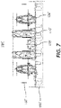
Fig. 7 is a schematic side view of a multi-band antenna according to some examples of the present disclosure. - Note, in the embodiments described below, the same signs are sometimes used in common between different attached drawings to denote the same parts or parts with the same functions, and repeated descriptions thereof are omitted. In some cases, similar labels and letters are used to indicate similar items. Therefore, once an item is defined in one attached drawing, it does not need to be further discussed in subsequent attached drawings.
- For ease of understanding, the position, dimension, and range of each structure shown in the attached drawings and the like may not indicate the actual position, dimension, and range. Therefore, the present disclosure is not limited to the position, size, range, etc. disclosed in the attached drawings.
- The present disclosure will be described below with reference to the attached drawings, which show several examples of the present disclosure. However, it should be understood that the present disclosure can be presented in many different ways and is not limited to the examples described below. In fact, the examples described below are intended to make the present disclosure more complete and to fully explain the protection scope of the present disclosure to those skilled in the art. It should also be understood that the examples disclosed in the present disclosure may be combined in various ways so as to provide more additional examples.
- It should be understood that the terms used herein are only used to describe specific examples, and are not intended to limit the scope of the present disclosure. All terms used herein (including technical terms and scientific terms) have meanings normally understood by those skilled in the art unless otherwise defined. For brevity and/or clarity, well-known functions or structures may not be further described in detail.
- As used herein, when an element is said to be "on" another element, "attached" to another element, "connected" to another element, "coupled" to another element, or "in contact with" another element, etc., the element may be directly on another element, attached to another element, connected to another element, coupled to another element, or in contact with another element, or an intermediate element may be present. In contrast, if an element is described "directly" "on" another element, "directly attached" to another element, "directly connected" to another element, "directly coupled" to another element or "directly in contact with" another element, there will be no intermediate elements. As used herein, when one feature is arranged "adjacent" to another feature, it may mean that one feature has a part overlapping with the adjacent feature or a part located above or below the adjacent feature.
- In this Specification, elements, nodes or features that are "connected" together may be mentioned. Unless explicitly stated otherwise, "connected" means that one element/node/feature can be mechanically, electrically, logically or otherwise connected with another element/node/feature in a direct or indirect manner to allow interaction, even though the two features may not be directly connected. That is, "connected" means direct and indirect connection of components or other features, including connection using one or a plurality of intermediate components.
- As used herein, spatial relationship terms such as "upper", "lower", "left", "right", "front", "back", "high" and "low" can explain the relationship between one feature and another in the drawings. It should be understood that, in addition to the orientations shown in the attached drawings, the terms expressing spatial relations also comprise different orientations of a device in use or operation. For example, when a device in the attached drawings rotates reversely, the features originally described as being "below" other features now can be described as being "above" the other features. The device may also be oriented by other means (rotated by 90 degrees or at other locations), and at this time, a relative spatial relation will be explained accordingly.
- As used herein, the term "A or B" comprises "A and B" and "A or B", not exclusively "A" or "B", unless otherwise specified.
- As used herein, the term "exemplary" means "serving as an example, instance or explanation", not as a "model" to be accurately copied. Any realization method described exemplarily herein may not be necessarily interpreted as being preferable or advantageous over other realization methods. Furthermore, the present disclosure is not limited by any expressed or implied theory given in the above technical field, background art, summary of the invention or specific embodiments.
- As used herein, the word "basically" means including any minor changes caused by design or manufacturing defects, device or component tolerances, environmental influences, and/or other factors. The word "basically" also allows the gap from the perfect or ideal situation due to parasitic effects, noise, and other practical considerations that may be present in the actual realization.
- In addition, for reference purposes only, "first", "second" and similar terms may also be used herein, and thus are not intended to be limitative. For example, unless the context clearly indicates, the words "first", "second" and other such numerical words involving structures or elements do not imply a sequence or order.
- It should also be understood that when the term "comprise/include" is used herein, it indicates the presence of the specified feature, entirety, step, operation, unit and/or component, but does not exclude the presence or addition of one or a plurality of other features, steps, operations, units and/or components and/or combinations thereof.
- As discussed above, in multi-band antennas, it may be important to reduce the scattering effect that the low-band radiating elements may have on the mid-band radiating elements, so as to avoid undesired distortion of the radiation pattern. An aspect of the present disclosure provides a multi-band antenna, which includes: a first radiating element, for example, a low-band radiating element, configured to be capable of operating within a first frequency band and emitting first electromagnetic radiation within the first frequency band; a second radiating element, for example, a mid-band radiating element, configured to be capable of operating within a second frequency band different from the first frequency band and emitting second electromagnetic radiation within the second frequency band; and a metamaterial adjusting element, configured to at least partially reflect the second electromagnetic radiation incident on the metamaterial adjusting element such that the reflected second electromagnetic radiation is redirected so as to at least partially cancel or offset the interference, for example, scattering effect, of the first radiating element to the second radiating element. Therefore, the multi-band antenna, according to the present disclosure, can improve the shape of the radiation pattern generated by the second radiating element.
- The multi-band antenna, according to some examples of the present disclosure, will now be described in more detail with reference to the drawings. It should be noted that the multi-band antenna may also have other components, and in order to avoid obscuring the main points of the present disclosure, the other components are not shown in the attached drawings and will not be discussed herein. It should also be noted that the drawings only schematically show the relative positional relationship of various components, and there is no particular limitation on the specific structure of each component.
- Referring to
Figs. 1 ,2a, 2b, and 2c ,Fig. 1 is a schematic perspective view of amulti-band antenna 100 according to some examples of the present disclosure;Fig. 2a is a schematic front view of themulti-band antenna 100 inFig. 1 ;Fig. 2b is a schematic side view of themulti-band antenna 100 taken along the line A-A ofFig. 2a; Fig. 2c is a schematic end view of themulti-band antenna 100 taken along the line B-B ofFig. 2a . - Referring to
Fig. 1 , themulti-band antenna 100 may be mounted for operation on a raised structure, such as an antenna tower, a telegraph pole, a building, a water tower, etc., such that a longitudinal axis of theantenna 100 extends roughly perpendicular to the ground. Theantenna 100 usually includes a radome (not shown) that provides environmental protection. Themulti-band antenna 100 includes areflector 160, which may comprise a metal surface that provides a ground plane and reflects electromagnetic radiation reaching the metal surface such that the electromagnetic radiation is redirected to propagate, for example, forwardly. Theantenna 100 may further include additional mechanical and electronic components, such as one or more of connectors, cables, phase shifters, remote electronic tilt (RET) units, duplexers, and the like, arranged on a rear side of thereflector 160. - The
multi-band antenna 100 may further include first radiatingelements 110 andsecond radiating elements 120 that are arranged on a front side of thereflector 160. In the illustrated examples, thefirst radiating elements 110 are arranged as two vertically extending linear arrays adjacent to each other in a horizontal direction. Thesecond radiating elements 120 are likewise arranged as two vertically extending linear arrays adjacent to each other in the horizontal direction. The two linear arrays ofsecond radiating elements 120 may be arranged between the two linear arrays offirst radiating elements 110 to reduce the width of the antenna. - An operating frequency band of the
first radiating elements 110 may be, for example, 617 to 960 MHz or a sub-band thereof. An operating frequency band of thesecond radiating elements 120 may be, for example, 1427 to 2690 MHz or a sub-band thereof. In other words, thefirst radiating elements 110 may be configured as low-band radiating elements that can operate within a first frequency band, for example 617 to 960 MHz or a sub-band thereof, and emit first electromagnetic radiation within the first frequency band. Thesecond radiating elements 120 may be configured as mid-band radiating elements that can operate within a second frequency band, for example 1427 to 2690 MHz or a sub-band thereof, and emit second electromagnetic radiation within the second frequency band. Depending on how thefirst radiating elements 110 are fed, the two linear arrays may be configured to form two separate first antenna beams (per polarization) within the first frequency band, or may be configured to form a single antenna beam (per polarization) within the first frequency band. Depending on how thesecond radiating elements 120 are fed, the two linear arrays may be configured to form two separate second antenna beams (per polarization) within the second frequency band, or may be configured to form a single first antenna beam (per polarization) within the second frequency band. - The
multi-band antenna 100 may further include ametamaterial adjusting element 140 arranged on the front side of thereflector 160 to cooperate with thesecond radiating element 120, thereby at least partially cancelling a negative effect, for example, distortion of the radiation pattern of the second antenna beam, caused by the interference, such as scattering effect, of thefirst radiating element 110 to thesecond radiating element 120. - In the present disclosure, the
metamaterial adjusting element 140 should be understood as a structure constituted by metamaterials or including metamaterials for adjusting the radio frequency performance of the antenna. Metamaterials are man-made materials with special properties that allow electromagnetic waves to change the general properties of the metamaterials. The properties of metamaterials stem from their precise geometric structure and size. In the present disclosure, metamaterials should be understood broadly, that is, metamaterials can include all periodic electromagnetic materials, such as frequency selective surfaces, electromagnetic band gap structures, metasurfaces, artificial magnetic conductors, photonic band gap structures, surface plasmons, and the like. - In some examples, the
metamaterial adjusting element 140 may be configured as a frequency selective surface. The frequency selective surface can filter electromagnetic waves in space. By periodically arranging a plurality of frequency selective surface units 1401, such as passive resonance units, on a two-dimensional plane, a metamaterial with a specific reflection/transmission phase distribution can be formed. When electromagnetic waves are incident on the frequency selective surface, the frequency selective surface can selectively pass or block electromagnetic waves of different frequencies. - As in the illustrated example, the frequency selective surface may be configured as a printed circuit board element, and the periodically arranged frequency selective surface units 1401 may be printed on the printed circuit board element.
Fig. 3a shows an exemplary frequency selective surface unit 1401. In some examples, a column of frequency selective surface units 1401 may be printed on the printed circuit board element to form a one-dimensional period of the frequency selective surface units 1401, as shown inFig. 3b . In some examples, a plurality of rows and a plurality of columns of frequency selective surface units 1401 may be printed on the printed circuit board element to form a two-dimensional period of the frequency selective surface units 1401, as shown inFig. 3c . In some examples, as shown inFig. 3d , the spacing between the frequency selective surface units 1401 may also be adjusted according to actual application scenarios. - It should be understood that there may be various design forms of the frequency selective surface and it is not limited to the specific examples listed here. The resonant frequency point and/or operating bandwidth of the frequency selective surface may be adjusted by designing various sizes of the frequency selective surface unit 1401 to meet the requirements of different resonance points, multi-frequency resonance, and/or broadband resonance in different application scenarios. In the current example, the frequency selective surface is designed as a cost-effective single-layer PCB element. In other examples, the frequency selective surface may be designed as a multi-layer PCB element to realize wideband and ultra-wideband operating bandwidth. In addition, the frequency selective surface may also be constituted by periodically arranged metal patch units, which may be less expensive to fabricate than printed circuit board based frequency selective surfaces.
- Continuing to refer to the illustrated examples, the
multi-band antenna 100 may include a plurality ofmetamaterial adjusting elements 140 for a plurality ofsecond radiating elements 120, and thesemetamaterial adjusting elements 140 may be arranged as ametamaterial adjusting element 140 array around the linear arrays ofsecond radiating elements 120 and behind the first radiating elements. Themetamaterial adjusting elements 140 may, for example, be designed to reflect the second electromagnetic radiation incident thereon while passing the first electromagnetic radiation incident thereon. Through this arrangement, themetamaterial adjusting elements 140 can at least partially reflect the second electromagnetic radiation incident on themetamaterial adjusting elements 140 such that the reflected second electromagnetic radiation is redirected without substantially impacting the radiation patterns of the linear arrays offirst radiating elements 110. Themetamaterial adjusting elements 140 can at least partially cancel the scattering effect of thefirst radiating elements 110 on thesecond radiating elements 120 by multi-path transmission of the electromagnetic radiation. - Referring to
Figs. 4a and4b ,Fig. 4a schematically shows a schematic diagram of the scattering effect of thefirst radiating element 110 on thesecond radiating element 120, andFig. 4b schematically shows a schematic diagram of at least partially cancelling the scattering effect by themetamaterial adjusting element 140. - As shown in
Fig. 4a , thefirst radiating element 110 is in front of thesecond radiating element 120 and at least partially covers thesecond radiating element 120, and thus the electromagnetic radiation emitted forward by thesecond radiating element 120 is at least incident on a radiator of thefirst radiating element 110. A dipole arm of the radiator of thefirst radiating element 110 can be regarded as an LC resonance structure with a resonant frequency within the aforementioned first frequency band, and the LC resonance structure will inevitably introduce a secondary resonance, which may fall into the aforementioned second frequency band, for example, near 1950 MHz. Therefore, during operation of thesecond radiating elements 120, a current within the second frequency band will be induced on the dipole arm of thefirst radiating element 110, thereby causing a scattering effect on the radiation emitted by thesecond radiating element 120. In the illustrated example, the second electromagnetic radiation emitted by onesecond radiating element 120 is incident on a radiator of onefirst radiating element 110 and is radiated backward by the radiator of thefirst radiating element 110 due to the scattering effect, thus changing the original radiation direction of a portion of the second electromagnetic radiation. As a result, the radiation pattern of the second antenna beam of thesecond radiating element 120 array may be distorted. - As shown in
Fig. 4b , themetamaterial adjusting elements 140 may be arranged on an outer peripheral side of thefirst radiating element 110 array and thesecond radiating element 120 array. In other words, the firstmetamaterial adjusting element 140 is arranged on the left side of the linear arrays offirst radiating elements 110 and the linear arrays ofsecond radiating elements 120, and the secondmetamaterial adjusting element 140 is arranged on the right side of the linear arrays offirst radiating elements 110 and the linear arrays ofsecond radiating elements 120. With this arrangement of themetamaterial adjusting elements 140, the second electromagnetic radiation emitted by thesecond radiating element 120 that is scattered from the forward direction by the first radiating elements may be incident on themetamaterial adjusting elements 140 and be radiated forward by the metamaterial adjusting elements 140 (see the transmission paths indicated by the solid line). Therefore, themetamaterial adjusting element 140 realizes a multipath transmission of a portion of the second electromagnetic radiation to at least partially cancel the interference caused by the scattering effect. - In some examples, although the
metamaterial adjusting element 140 is arranged behind thefirst radiating element 110, it should also be considered that sidelobes and/or backlobes of the first antenna beam may be incident on themetamaterial adjusting element 140. In order to prevent themetamaterial adjusting element 140 from producing undesired interference to the first antenna beam of thefirst radiating element 110 array, themetamaterial adjusting element 140 may be configured as a spatial band-stop filter so that the first electromagnetic radiation within the first frequency band or a sub-band thereof can be transmitted through themetamaterial adjusting element 140, and the electromagnetic radiation within the second frequency band or a sub-band thereof is basically blocked, for example, reflected, by themetamaterial adjusting element 140. Therefore, themetamaterial adjusting element 140 can at least partially avoid the distortion of the radiation pattern of the second antenna beam caused by the scattering effect while reducing the negative effect on the radiation pattern of the first antenna beam. - In an actual tuning process, many influencing factors need to be considered, such as: the number of the
metamaterial adjusting elements 140, the orientation and/or distance of themetamaterial adjusting element 140 relative to the reflector (that is, an angle of an acting surface of themetamaterial adjusting element 140 toward thesecond radiating element 120 and/or a forward extending dimension of the acting surface of the metamaterial adjusting element 140), and the distance of themetamaterial adjusting element 140 to thesecond radiating element 120. Therefore, one or more of the aforementioned influencing factors may be adjusted appropriately according to the actual tuning situation to tune the pattern of the second antenna beam, so that the pattern of the second antenna beam meets desired requirements such as -3dB lobe width, - 10dB lobe width, and/or pattern shape, etc. - Next, referring to
Figs. 5a and 5b , embodiments of the radiator of thefirst radiating element 110 in themulti-band antenna 100 according to some examples of the present disclosure will be further introduced. - In order to reduce the scattering effect of the
first radiating element 110 on thesecond radiating element 120, the radiator of thefirst radiating element 110 may be designed as a cloaked radiator. Thefirst radiating element 110 includes a radiator with a dipole arm that includes a narrowedarm segment 370 and awidened arm segment 380. Thenarrowed arm segment 370 and thewidened arm segment 380 can form at least one resonance structure that is configured to at least partially attenuate currents within at least part of the frequency range of the second frequency band that could otherwise be induced on the dipole arm itself. -
Fig. 5a and Fig. 5b show two typical embodiments of the radiator of thefirst radiating element 110. InFig. 5a , afirst radiator 1101 of thefirst radiating element 110 extends obliquely at +45°, and asecond radiator 1102 of thefirst radiating element 110 extends obliquely at -45°. InFig. 5b , thefirst radiator 1101 of thefirst radiating element 110 may extend horizontally (that is, at 0°), and thesecond radiator 1102 of thefirst radiating element 110 may extend vertically (that is, at 90°). Each dipole arm of each radiator may include at least onenarrowed arm segment 370 and at least onewidened arm segment 380. Each arm may include two conductive paths, wherein a first conductive path forms half of the generally elongated dipole arm and a second conductive path forms the other half of the dipole arm. Each conductive path may include a metal pattern that has a widenedarm segment 380 and anarrowed arm segment 370. Thenarrowed arm segment 370 may be configured as a meandered arm segment to increase the path length thereof, thereby facilitating the compactness of thefirst radiating element 110 and/or a desired filtering effect. Thenarrowed arm segment 370 may be realized as a non-linear conductive segment, and may act as a high impedance segment that interrupts currents in the second frequency band, that is, the mid-band, that could otherwise be induced on the dipole arm itself. As such, the narrowedarm segment 370 can reduce induced mid-band currents on thefirst radiating element 110, thereby further reducing the scattering effect of thefirst radiating element 110 on thesecond radiating element 120. Thenarrowed arm segment 370 may make thefirst radiating element 110 almost invisible to thesecond radiating element 120, and thus endows thefirst radiating element 110 with a cloaking function. It is advantageous for thefirst radiating element 110 to have a cloaking function because the less mid-band current induced on the dipole arm of thefirst radiating element 110, the smaller impact on the radiation pattern of thesecond radiating element 120 array. - Although the aforementioned
first radiating element 110 having a cloaking function can reduce the scattering effect, in some cases, the radiatingelement 110 may not be able to realize good cloaking function for the entire operating frequency band of thesecond radiating element 120. For example, it may be possible that thefirst radiating element 110 may produce undesired interference at one or more frequency point or sub-bands within the operating frequency band of thesecond radiating element 120. - In an actual tuning process, in order to design a suitable
metamaterial adjusting element 140, the following steps of a method may be carried out. First, testing and analyzing the radiation pattern of the second antenna beam of thesecond radiating element 120 array at a plurality of frequency points within the second frequency band is performed. Then, it is determined whether the performance of the radiation pattern of the second antenna beam at the at least one frequency point needs to be improved according to design requirements; in other words, thefirst radiating element 110 may have a non-negligible scattering effect on thesecond radiating element 120 at the at least one frequency point, and the design requirements may be, for example, -3dB lobe width, -10dB lobe width, and/or pattern shape, etc. Last, ametamaterial adjusting element 140 is designed for the at least one frequency point such that themetamaterial adjusting element 140 shows reflection characteristics at the at least one frequency point. - In some examples, when the resonance structure formed on the radiator of the
first radiating element 110 attenuates currents within a first portion of a frequency range of the second frequency band according to the design requirements, themetamaterial adjusting element 140 may be configured to at least reflect the second electromagnetic radiation incident on themetamaterial adjusting element 140 within a second portion of the frequency range of the second frequency band, wherein the superposition of the first portion of frequency range and the second portion of frequency range can cover the second frequency band. In other words, themetamaterial adjusting element 140 may be designed for the at least one frequency point such that themetamaterial adjusting element 140 is configured as a spatial band-stop filter, the stop band of which covers the at least one frequency point. Therefore, the combination of the cloaking function of thefirst radiating element 110 and the frequency selective characteristics of themetamaterial adjusting element 140 can reduce the interference from thefirst radiating element 110 over a wider frequency band, for example, the entire operating frequency band of thesecond radiating element 120, thereby improving the radiation pattern of the second antenna beam of thesecond radiating element 120 array. -
Figs. 6a to 6c are azimuth patterns for a multi-band antenna with a metamaterial adjusting element and a multi-band antenna without a metamaterial adjusting element at 1.9 GHz, 1.95 GHz, and 2.0 GHz, respectively according to some examples of the present disclosure. As shown in the figures, the shape of the azimuth pattern of the multi-band antenna at the selected frequency points can be effectively improved by the metamaterial adjusting element. - Next, referring to
Fig. 7 , a schematic end view of themulti-band antenna 100 according to some examples of the present disclosure will be further introduced. - Another typical multi-band antenna 100' is shown in
Fig. 7 . The multi-band antenna 100' may include first radiating elements 110', second radiating elements 120', and third radiating elements 130' that are arranged on a front side of a reflector 160'. In the illustrated example, the second radiating elements 120' are arranged as two vertically extending linear arrays that are adjacent to each other in a horizontal direction. Depending on how these radiating elements 110' are fed, the two linear arrays of second radiating elements 120' may be configured to form two separate antenna beams, or may be configured to form a single antenna beam. The third radiating elements 130' may be arranged as a linear array that is disposed between the two linear arrays of second radiating elements 120'. The first radiating elements 110' are arranged staggered on both sides of a vertical central axis of the linear array of third radiating elements 130' slightly deviated from the axis, so as to obtain an antenna beam with a narrower beam width in the azimuth plane. - An operating frequency band of the first radiating elements 110' may be, for example, 617 to 960 MHz or a sub-band thereof. An operating frequency band of the second radiating elements 120' may be, for example, 1427 to 2690 MHz or a sub-band thereof. An operating frequency band of the third radiating elements 130' may be, for example, 3.1 to 4.2 GHz or a sub-band thereof. In other words, the first radiating elements 110' may be configured as low-band radiating elements that can operate within a first frequency band, for example 617 to 960 MHz or a sub-band thereof, and emit first electromagnetic radiation within the first frequency band. The second radiating elements 120' may be configured as mid-band radiating elements that can operate within a second frequency band, for example 1427 to 2690 MHz or a sub-band thereof, and emit second electromagnetic radiation within the second frequency band. The third radiating elements 130' may be configured as high-band radiating elements that can operate within a third frequency band, for example 3.1 to 4.2 GHz or a sub-band thereof, and emit third electromagnetic radiation within the third frequency band. For this type of multi-band antenna 100', a metamaterial adjusting element 140' may be designed as a spatial band-stop filter with frequency selective characteristics, and the stop band of the spatial band-stop filter covers the frequency band 1427 to 2690 MHz or a sub-band thereof such that the electromagnetic radiation within the first frequency band and the third frequency band can be transmitted through the metamaterial adjusting element 140' and the electromagnetic radiation within the second frequency band or a sub-band thereof is at least partially reflected by the metamaterial adjusting element 140'.
- It should be understood that radiating elements with any operating frequency band may be introduced in the
multi-band antennas 100 and 100', and the number and arrangement of the radiating element arrays in each frequency band may also vary. By introducing themetamaterial adjusting elements 140 and 140' into themulti-band antennas 100 and 100' and cooperating with radiating elements in certain frequency bands, the radiation patterns of the antenna beams of themulti-band antennas 100 and 100' can be effective adjusted. - Although some specific examples of the present disclosure have been described in detail by examples, those skilled in the art should understand that the above examples are only for illustration, not for limiting the scope of the present disclosure. The examples disclosed herein can be combined arbitrarily without departing from the spirit and scope of the present disclosure. Those skilled in the art should also understand that various modifications can be made to the examples without departing from the scope and spirit of the present disclosure. The scope of the present disclosure is defined by the Claims attached.
- The preferred aspects of the present disclosure may be summarized as follows:
- 1. A multi-band antenna, including:
- a first radiating element, configured to operate within a first frequency band and to emit first electromagnetic radiation within the first frequency band;
- a second radiating element, configured to operate within a second frequency band different from the first frequency band and to emit second electromagnetic radiation within the second frequency band; and
- a metamaterial adjusting element, configured to at least partially reflect the second electromagnetic radiation incident on the metamaterial adjusting element such that the reflected second electromagnetic radiation is redirected to at least partially cancel the interference of the first radiating element to the second radiating element.
- 2. The multi-band antenna according to
aspect 1, wherein the metamaterial adjusting element is configured to be substantially invisible to the first electromagnetic radiation, so that the first electromagnetic radiation incident on the metamaterial adjusting element can be substantially transmitted through the metamaterial adjusting element. - 3. The multi-band antenna according to any one of the preceding aspects, in
particular aspect 1, wherein the second electromagnetic radiation emitted by the second radiating element includes a portion that is incident on the first radiating element and is radiated backward by the first radiating element due to a scattering effect such that it is incident on the metamaterial adjusting element and is radiated forward by the metamaterial adjusting element. - 4. The multi-band antenna according to any one of the preceding aspects, in
particular aspect 1, wherein the metamaterial adjusting element is configured as a frequency selective surface. - 5. The multi-band antenna according to any one of the preceding aspects, in
particular aspect 1, wherein the multi-band antenna further includes a third radiating element, configured to emit third electromagnetic radiation within a third frequency band different from the first frequency band and the second frequency band. - 6. The multi-band antenna according to any one of the preceding aspects, in particular aspect 5, wherein the metamaterial adjusting element is configured to be substantially invisible to the third electromagnetic radiation, so that the third electromagnetic radiation incident on the metamaterial adjusting element is substantially transmitted through the metamaterial adjusting element.
- 7. The multi-band antenna according to any one of the preceding aspects, in particular aspect 5, wherein the metamaterial adjusting element is configured to reflect the third electromagnetic radiation incident on the metamaterial adjusting element, so that the reflected third electromagnetic radiation is redirected.
- 8. The multi-band antenna according to any one of the preceding aspects, in
particular aspect 1, wherein the first radiating element includes a radiator including a first dipole arm and a second dipole arm, and the first dipole arm and the second dipole arm each include a narrowed high impedance arm segment and a widened arm segment. - 9. The multi-band antenna according to any one of the preceding aspects, in
particular aspect 1, wherein the first dipole arm and the second dipole arm each include a first conductive path and a second conductive path, and the first conductive path and the second conductive path each include at least one narrowed arm segment and at least one widened arm segment. - 10. The multi-band antenna according to any one of the preceding aspects, in particular aspect 9, wherein the first conductive path and the second conductive path together form a conductive loop.
- 11. The multi-band antenna according to any one of the preceding aspects, in particular aspect 9, wherein the narrowed arm segment and the widened arm segment form at least one resonant structure, and the resonant structure is configured to at least partially attenuate currents within the second frequency band that could otherwise be induced on the first dipole arm and the second dipole arm.
- 12. The multi-band antenna according to any one of the preceding aspects, in particular aspect 11, wherein the resonant structure attenuates currents within a first portion of frequency range of the second frequency band, and the metamaterial adjusting element is configured to at least reflect the second electromagnetic radiation incident on the metamaterial adjusting element within a second portion of frequency range of the second frequency band, wherein the superposition of the first portion of frequency range and the second portion of frequency range covers the second frequency band.
- 13. The multi-band antenna according to any one of the preceding aspects, in
particular aspect 1, wherein the first frequency band is a 617 to 960 MHz frequency range or a portion thereof, and the second frequency band is a 1427 to 2690 MHz frequency range or a portion thereof. - 14. The multi-band antenna according to any one of the preceding aspects, in
particular aspect 1, wherein the metamaterial adjusting element is configured as a spatial band-stop filter such that the electromagnetic radiation within the first frequency band is transmitted through the metamaterial adjusting element, and the electromagnetic radiation within the second frequency band is substantially reflected by the metamaterial adjusting element. - 15. A multi-band antenna, including:
- a first radiating element array, including a plurality of first radiating elements, the first radiating element array being configured to operate within a first frequency band and to generate a first antenna beam within the first frequency band;
- a second radiating element array, including a plurality of second radiating elements, the second radiating element array being configured to operate within a second frequency band and to generate a second antenna beam within the second frequency band; and
- a metamaterial adjusting element array, including a plurality of metamaterial adjusting elements for the plurality of second radiating elements, wherein the plurality of metamaterial adjusting elements are arranged around the second radiating element array and at least partially behind the first radiating element array, and each metamaterial adjusting element is configured to have frequency selective characteristics, so that the metamaterial adjusting element array is configured to adjust the radiation pattern of the second antenna beam.
- 16. The multi-band antenna according to any one of the preceding aspects, in particular aspect 15, wherein each metamaterial adjusting element is configured as a spatial band-stop filter such that the electromagnetic radiation within the first frequency band can be transmitted through the metamaterial adjusting element, and the electromagnetic radiation within the second frequency band is basically reflected by the metamaterial adjusting element.
- 17. The multi-band antenna according to any one of the preceding aspects, in particular aspect 16, wherein each metamaterial adjusting element is configured to at least partially reflect the second electromagnetic radiation within the second frequency band incident on the metamaterial adjusting element such that the reflected second electromagnetic radiation is redirected to at least partially cancel a scattering effect of the first radiating element on the second electromagnetic radiation.
- 18. The multi-band antenna according to any one of the preceding aspects, in particular aspect 17, wherein the second electromagnetic radiation emitted by one of the second radiating elements is incident on one of the first radiating elements and is radiated backward by the one of the first radiating elements due to the scattering effect such that it is incident on one of the metamaterial adjusting elements and is radiated forward by the one of metamaterial adjusting elements.
- 19. The multi-band antenna according to any one of the preceding aspects, in particular aspect 16, wherein the metamaterial adjusting element is configured to be basically invisible to the first electromagnetic radiation within the first frequency band.
- 20. The multi-band antenna according to any one of the preceding aspects, in particular aspect 15, wherein each metamaterial adjusting element is configured as a frequency selective surface.
- 21. The multi-band antenna according to any one of the preceding aspects, in particular aspect 18, wherein each frequency selective surface includes passive resonant units arranged periodically, so that the frequency selective surface exhibits total reflection characteristics at the resonant frequency of the passive resonance unit.
- 22. The multi-band antenna according to any one of the preceding aspects, in particular aspect 21, wherein the frequency selective surface is configured as a printed circuit board element.
- 23. The multi-band antenna according to any one of the preceding aspects, in particular aspect 15, wherein the plurality of metamaterial adjusting elements are arranged on an outer peripheral side of the first radiating element array and the second radiating element array.
- 24. A multi-band antenna, including:
- a first radiating element array, including a plurality of first radiating elements, the first radiating element array being configured to operate within a first frequency band and to generate a first antenna beam within the first frequency band;
- a second radiating element array, including a plurality of second radiating elements, the second radiating element array being configured to operate within a second frequency band and to generate a second antenna beam within the second frequency band;
- wherein each first radiating element includes a radiator including a first dipole arm and a second dipole arm, the first dipole arm and the second dipole arm each include a narrowed arm segment and a widened arm segment, and the narrowed arm segment and the widened arm segment form at least one resonant structure,
- the multi-band antenna further including:
a metamaterial adjusting element array, including a plurality of metamaterial adjusting elements respectively for the plurality of second radiating elements, wherein the plurality of metamaterial adjusting elements and the resonant structure cooperate with each other to suppress the interference of the first radiating element on the second radiating element.
- 25. The multi-band antenna according to any one of the preceding aspects, in particular aspect 24, wherein the resonant structure is configured to attenuate currents within a first portion of the second frequency band, and the metamaterial adjusting element is configured to at least reflect the second electromagnetic radiation incident on the metamaterial adjusting element within a second portion of the second frequency band, wherein the superposition of the first portion and the second portion covers the second frequency band.
- 26. A method for tuning a multi-band antenna, the multi-band antenna including a reflector and a first radiating element array and a second radiating element array mounted on the reflector, the first radiating element array including a plurality of first radiating elements, the first radiating element array being configured to operate within a first frequency band and to generate a first antenna beam within the first frequency band; the second radiating element array including a plurality of second radiating elements, the second radiating element array being configured to operate within a second frequency band and to generate a second antenna beam within the second frequency band,
wherein the method includes:- arranging a metamaterial adjusting element around the second radiating element array and at least partially behind the first radiating element array;
- adjusting the orientation and/or distance of the metamaterial adjusting element relative to the reflector, and/or adjusting the distance of the metamaterial adjusting element to the second radiating element array, so as to tune the pattern of the second antenna beam.
- 27. The method according to any one of the preceding aspects, in particular aspect 26, further including:
adjusting the orientation and/or distance of the metamaterial adjusting element relative to the reflector, and/or adjusting the distance of the metamaterial adjusting element to the second radiating element array, so as to at least partially reflect second electromagnetic radiation incident on the metamaterial adjusting element such that the reflected second electromagnetic radiation is redirected to at least partially cancel a scattering effect of the first radiating element array on electromagnetic radiation emitted by the second radiating element array. - 28. A method for tuning a multi-band antenna, the multi-band antenna including a reflector and a first radiating element array and a second radiating element array mounted on the reflector, the first radiating element array including a plurality of first radiating elements, the first radiating element array being configured to operate within a first frequency band and to generate a first antenna beam within the first frequency band; the second radiating element array including a plurality of second radiating elements, the second radiating element array being configured to operate within a second frequency band and to generate a second antenna beam within the second frequency band, wherein each first radiating element includes a radiator including a first dipole arm and a second dipole arm, the first dipole arm and the second dipole arm each include a narrowed arm segment and a widened arm segment, the narrowed arm segment and the widened arm segment form at least one resonant structure, and the resonant structure attenuates currents within a first portion of frequency range of the second frequency band,
wherein the method includes:- analyzing the radiation pattern of the second antenna beam at a plurality of frequency points within the second frequency band; and
- designing a metamaterial adjusting element for at least one frequency point such that the metamaterial adjusting element shows reflection characteristics at the at least one frequency point.
- 29. The method according to any one of the preceding aspects, in particular aspect 28, further including:
designing a metamaterial adjusting element for the at least one frequency point, and configuring the metamaterial adjusting element as a spatial band-stop filter, the stop band of the spatial band-stop filter covering the at least one frequency point. - 30. The method according to any one of the preceding aspects, in particular aspect 29, further including: configuring the metamaterial adjusting element as a spatial band-stop filter, wherein the superposition of the stop band of the spatial band-stop filter and the first portion of frequency range of the resonant structure covers the second frequency band.
- 31. A multi-band antenna, including:
- a reflector;
- a first radiating element that is configured to operate within a first frequency band;
- a second radiating element that is configured to operate within a second frequency band different from the first frequency band; and
- a metamaterial adjusting element mounted to extend forwardly from the reflector, the metamaterial adjusting element configured to substantially reflect electromagnetic radiation incident on the metamaterial adjusting element that is within a first portion of the second frequency band.
- 32. The multi-band antenna of any one of the preceding aspects, in particular aspect 31, wherein the metamaterial adjusting element is configured to substantially pass electromagnetic radiation incident on the metamaterial adjusting element that is within the first frequency band.
- 33. The multi-band antenna of any one of the preceding aspects, in particular aspect 31, wherein the metamaterial adjusting element is configured to substantially pass electromagnetic radiation incident on the metamaterial adjusting element that is within a second portion of the second frequency band
- 34. The multi-band antenna of any one of the preceding aspects, in particular aspect 31, wherein a major surface of the metamaterial adjusting element is mounted at an angle of between 65 degrees and 115 degrees with respect to the front surface of the reflector.
Claims (15)
- A multi-band antenna, including:a reflector;a first radiating element that is mounted to extend forwardly from the reflector and configured to operate within a first frequency band;a second radiating element that is mounted to extend forwardly from the reflector and configured to operate within a second frequency band that is different from the first frequency band; anda metamaterial adjusting element that is mounted to extend forwardly from the reflector and configured to reflect electromagnetic radiation incident on the metamaterial adjusting element that is within a first portion of the second frequency band.
- The multi-band antenna of claim 1, wherein the metamaterial adjusting element is configured to pass electromagnetic radiation incident on the metamaterial adjusting element that is within the first frequency band.
- The multi-band antenna of any of claims 1 or 2, wherein the metamaterial adjusting element is configured to pass electromagnetic radiation incident on the metamaterial adjusting element that is within a second portion of the second frequency band.
- The multi-band antenna of any of claims 1-3, wherein a major surface of the metamaterial adjusting element is mounted at an angle of between 65 degrees and 115 degrees with respect to a front surface of the reflector.
- The multi-band antenna of any of claims 1-4, wherein the first radiating element, the second radiating element and the metamaterial adjusting element are configured so that the first radiating element redirects backwardly a first portion of the electromagnetic radiation emitted by the second radiating element via a scattering effect such that it is incident on the metamaterial adjusting element, and the metamaterial adjusting element redirects forwardly at least some of the first portion of the electromagnetic radiation.
- The multi-band antenna of any of claims 1-5, wherein the second radiating element is on a first side of the first radiating element and the metamaterial adjusting element is on a second, opposed side of the first radiating element and is behind the first radiating element.
- The multi-band antenna of any of claims 1-6, wherein the metamaterial adjusting element is configured to reduce an impact of the first radiating element on the radiation pattern of the second radiating element.
- The multi-band antenna according to any of claims 1-7, wherein the metamaterial adjusting element includes a frequency selective surface.
- The multi-band antenna according to claim 8, wherein the frequency selective surface includes a plurality of periodically arranged passive resonant units.
- The multi-band antenna according to any of claims 1-9, wherein the multi-band antenna further includes a third radiating element that is mounted to extend forwardly from the reflector and configured to operate within a third frequency band different from the first frequency band and the second frequency band, and the metamaterial adjusting element is configured to pass electromagnetic radiation incident on the metamaterial adjusting element that is within the third frequency band.
- The multi-band antenna according to any of claims 1-9, wherein the multi-band antenna further includes a third radiating element that is mounted to extend forwardly from the reflector and configured to operate within a third frequency band different from the first frequency band and the second frequency band, and the metamaterial adjusting element is configured to reflect electromagnetic radiation incident on the metamaterial adjusting element that is within the third frequency band.
- The multi-band antenna according to any of claims 1-11, wherein the first frequency band is a 617 to 960 MHz frequency range or a portion thereof, and the second frequency band is a 1427 to 2690 MHz frequency range or a portion thereof.
- The multi-band antenna according to any of claims 1-12, wherein the metamaterial adjusting element is configured as a spatial band-stop filter such that electromagnetic radiation within the first frequency band is transmitted through the metamaterial adjusting element, and electromagnetic radiation within the second frequency band is reflected by the metamaterial adjusting element.
- The multi-band antenna according to any of claims 1-13, wherein the first radiating element includes dipole arms that each include at least one resonant structure that is configured to at least partially attenuate currents within the second frequency band that could otherwise be induced thereon.
- The multi-band antenna according to claim 14, wherein each dipole arm forms a respective conductive loop.
Applications Claiming Priority (1)
| Application Number | Priority Date | Filing Date | Title |
|---|---|---|---|
| CN202110216447.2A CN114976627A (en) | 2021-02-26 | 2021-02-26 | Multi-band antenna and method for commissioning multi-band antenna |
Publications (2)
| Publication Number | Publication Date |
|---|---|
| EP4053996A1 true EP4053996A1 (en) | 2022-09-07 |
| EP4053996B1 EP4053996B1 (en) | 2026-04-22 |
Family
ID=80446865
Family Applications (1)
| Application Number | Title | Priority Date | Filing Date |
|---|---|---|---|
| EP22158144.0A Active EP4053996B1 (en) | 2021-02-26 | 2022-02-23 | Multi-band antenna |
Country Status (3)
| Country | Link |
|---|---|
| US (1) | US12027772B2 (en) |
| EP (1) | EP4053996B1 (en) |
| CN (1) | CN114976627A (en) |
Families Citing this family (5)
| Publication number | Priority date | Publication date | Assignee | Title |
|---|---|---|---|---|
| CN113809556A (en) * | 2021-08-05 | 2021-12-17 | 华南理工大学 | Common-caliber dual-frequency dual-polarized antenna array and communication equipment |
| US12555929B2 (en) * | 2022-07-11 | 2026-02-17 | Quintel Cayman Limited | Dual mode cloaking base station antenna system using frequency selective surfaces |
| WO2024147378A1 (en) * | 2023-01-04 | 2024-07-11 | 엘지전자 주식회사 | Device and method for steering beam in wireless communication system |
| WO2024155484A1 (en) * | 2023-01-16 | 2024-07-25 | Commscope Technologies Llc | Base station antennas having an external access port for receiving interchangeable frequency selective surfaces |
| CN120262029A (en) * | 2025-06-05 | 2025-07-04 | 西安电子科技大学 | A broadband, high-gain 5G base station antenna based on metasurface |
Citations (3)
| Publication number | Priority date | Publication date | Assignee | Title |
|---|---|---|---|---|
| WO2019009951A1 (en) * | 2017-07-05 | 2019-01-10 | Commscope Technologies Llc | Base station antennas having radiating elements with sheet metal-on dielectric dipole radiators and related radiating elements |
| WO2020200476A1 (en) * | 2019-04-05 | 2020-10-08 | Huawei Technologies Co., Ltd. | A multiband antenna system and method for providing the same |
| WO2020239190A1 (en) * | 2019-05-24 | 2020-12-03 | Huawei Technologies Co., Ltd. | Multi-band antenna with a frequency selective device for improved isolation of radiating elements |
Family Cites Families (5)
| Publication number | Priority date | Publication date | Assignee | Title |
|---|---|---|---|---|
| US7420524B2 (en) * | 2003-04-11 | 2008-09-02 | The Penn State Research Foundation | Pixelized frequency selective surfaces for reconfigurable artificial magnetically conducting ground planes |
| GB2467763B (en) * | 2009-02-13 | 2013-02-20 | Univ Kent Canterbury | Tuneable surface |
| CN212182533U (en) | 2020-06-10 | 2020-12-18 | 康普技术有限责任公司 | Base station antenna and multiband base station antenna |
| CN113782949A (en) * | 2020-06-10 | 2021-12-10 | 康普技术有限责任公司 | Base station antenna with frequency selective surface |
| CN112134017B (en) | 2020-08-04 | 2023-12-22 | 中国航空工业集团公司沈阳飞机设计研究所 | Decoupling method between airborne array antenna elements based on metamaterial and metamaterial |
-
2021
- 2021-02-26 CN CN202110216447.2A patent/CN114976627A/en active Pending
-
2022
- 2022-02-10 US US17/668,437 patent/US12027772B2/en active Active
- 2022-02-23 EP EP22158144.0A patent/EP4053996B1/en active Active
Patent Citations (3)
| Publication number | Priority date | Publication date | Assignee | Title |
|---|---|---|---|---|
| WO2019009951A1 (en) * | 2017-07-05 | 2019-01-10 | Commscope Technologies Llc | Base station antennas having radiating elements with sheet metal-on dielectric dipole radiators and related radiating elements |
| WO2020200476A1 (en) * | 2019-04-05 | 2020-10-08 | Huawei Technologies Co., Ltd. | A multiband antenna system and method for providing the same |
| WO2020239190A1 (en) * | 2019-05-24 | 2020-12-03 | Huawei Technologies Co., Ltd. | Multi-band antenna with a frequency selective device for improved isolation of radiating elements |
Also Published As
| Publication number | Publication date |
|---|---|
| CN114976627A (en) | 2022-08-30 |
| US12027772B2 (en) | 2024-07-02 |
| US20220278462A1 (en) | 2022-09-01 |
| EP4053996B1 (en) | 2026-04-22 |
Similar Documents
| Publication | Publication Date | Title |
|---|---|---|
| US11575197B2 (en) | Multi-band antenna having passive radiation-filtering elements therein | |
| EP4053996B1 (en) | Multi-band antenna | |
| EP3841637B1 (en) | Antennas including multi-resonance cross-dipole radiating elements and related radiating elements | |
| CN107275808B (en) | Ultra-wideband radiators and associated antenna arrays | |
| US12088017B2 (en) | Radiating element, antenna assembly and base station antenna | |
| US12506276B2 (en) | Broadband decoupling radiating elements and base station antennas having such radiating elements | |
| US20240283164A1 (en) | Radiating elements having dipole arms with cloaked dielectric loading elements and base station antennas including such radiating elements | |
| CN113690581A (en) | Antenna with a shield | |
| CN112768894A (en) | Multiband base station antenna with crossed dipole radiating elements | |
| US12451604B2 (en) | Multi-band antenna | |
| EP4312309A1 (en) | Radiating element and base station antenna | |
| US20250293441A1 (en) | Base station antennas having broadband decoupling radiating elements including metamaterial resonator based dipole arms | |
| CN113451751A (en) | Multi-band antenna, radiating element assembly and parasitic element assembly | |
| WO2024145734A1 (en) | Radiating elements having feed stalks with frequency selective surfaces and base station antennas including such radiating elements | |
| CN120303829A (en) | Base station antenna having a frequency selective surface having a unit cell including an inductor feature | |
| US11843161B2 (en) | Radiating element and base station antenna | |
| CN212182536U (en) | Multiband antenna | |
| EP4526954A1 (en) | Radiating element and base station antenna | |
| EP3893328A1 (en) | Multi-band antenna having passive radiation-filtering elements therein | |
| CN117134121A (en) | Antenna with super surface lens | |
| US20260094978A1 (en) | Base station antenna | |
| US20250300349A1 (en) | Lower band radiating elements having reduced scattering of higher-band radiation | |
| WO2024147987A1 (en) | Base station antennas having radiating elements with cloaked directors and/or multiple directors | |
| WO2025010303A2 (en) | Radiating elements with meta material lenses and related base station antennas | |
| WO2025240540A1 (en) | Base station antennas with low-band arrays having low-band radiating elements having parasitic monopole elements |
Legal Events
| Date | Code | Title | Description |
|---|---|---|---|
| PUAI | Public reference made under article 153(3) epc to a published international application that has entered the european phase |
Free format text: ORIGINAL CODE: 0009012 |
|
| STAA | Information on the status of an ep patent application or granted ep patent |
Free format text: STATUS: REQUEST FOR EXAMINATION WAS MADE |
|
| 17P | Request for examination filed |
Effective date: 20220223 |
|
| AK | Designated contracting states |
Kind code of ref document: A1 Designated state(s): AL AT BE BG CH CY CZ DE DK EE ES FI FR GB GR HR HU IE IS IT LI LT LU LV MC MK MT NL NO PL PT RO RS SE SI SK SM TR |
|
| STAA | Information on the status of an ep patent application or granted ep patent |
Free format text: STATUS: EXAMINATION IS IN PROGRESS |
|
| 17Q | First examination report despatched |
Effective date: 20240228 |
|
| RAP3 | Party data changed (applicant data changed or rights of an application transferred) |
Owner name: COMMSCOPE TECHNOLOGIES LLC |
|
| RAP1 | Party data changed (applicant data changed or rights of an application transferred) |
Owner name: OUTDOOR WIRELESS NETWORKS LLC |
|
| REG | Reference to a national code |
Ref country code: DE Ref legal event code: R079 Free format text: PREVIOUS MAIN CLASS: H01Q0001240000 Ipc: H01Q0001520000 Ref country code: DE Ref legal event code: R079 Ref document number: 602022034872 Country of ref document: DE Free format text: PREVIOUS MAIN CLASS: H01Q0001240000 Ipc: H01Q0001520000 |
|
| GRAP | Despatch of communication of intention to grant a patent |
Free format text: ORIGINAL CODE: EPIDOSNIGR1 |
|
| STAA | Information on the status of an ep patent application or granted ep patent |
Free format text: STATUS: GRANT OF PATENT IS INTENDED |
|
| RIC1 | Information provided on ipc code assigned before grant |
Ipc: H01Q 1/52 20060101AFI20251016BHEP Ipc: H01Q 5/30 20150101ALI20251016BHEP Ipc: H01Q 15/00 20060101ALI20251016BHEP Ipc: H01Q 19/10 20060101ALI20251016BHEP Ipc: H01Q 21/28 20060101ALI20251016BHEP Ipc: H01Q 1/24 20060101ALN20251016BHEP Ipc: H01Q 5/48 20150101ALN20251016BHEP Ipc: H01Q 21/06 20060101ALN20251016BHEP Ipc: H01Q 21/24 20060101ALN20251016BHEP |
|
| INTG | Intention to grant announced |
Effective date: 20251113 |
|
| GRAS | Grant fee paid |
Free format text: ORIGINAL CODE: EPIDOSNIGR3 |
|
| GRAA | (expected) grant |
Free format text: ORIGINAL CODE: 0009210 |
|
| STAA | Information on the status of an ep patent application or granted ep patent |
Free format text: STATUS: THE PATENT HAS BEEN GRANTED |
|
| AK | Designated contracting states |
Kind code of ref document: B1 Designated state(s): AL AT BE BG CH CY CZ DE DK EE ES FI FR GB GR HR HU IE IS IT LI LT LU LV MC MK MT NL NO PL PT RO RS SE SI SK SM TR |
|
| REG | Reference to a national code |
Ref country code: CH Ref legal event code: F10 Free format text: ST27 STATUS EVENT CODE: U-0-0-F10-F00 (AS PROVIDED BY THE NATIONAL OFFICE) Effective date: 20260422 Ref country code: GB Ref legal event code: FG4D |
|
| REG | Reference to a national code |
Ref country code: DE Ref legal event code: R096 Ref document number: 602022034872 Country of ref document: DE |