EP4053995A1 - Housing unit - Google Patents
Housing unit Download PDFInfo
- Publication number
- EP4053995A1 EP4053995A1 EP20881540.7A EP20881540A EP4053995A1 EP 4053995 A1 EP4053995 A1 EP 4053995A1 EP 20881540 A EP20881540 A EP 20881540A EP 4053995 A1 EP4053995 A1 EP 4053995A1
- Authority
- EP
- European Patent Office
- Prior art keywords
- resin container
- lid
- resin
- container
- drain
- Prior art date
- Legal status (The legal status is an assumption and is not a legal conclusion. Google has not performed a legal analysis and makes no representation as to the accuracy of the status listed.)
- Withdrawn
Links
- 239000011347 resin Substances 0.000 claims abstract description 157
- 229920005989 resin Polymers 0.000 claims abstract description 157
- XLYOFNOQVPJJNP-UHFFFAOYSA-N water Substances O XLYOFNOQVPJJNP-UHFFFAOYSA-N 0.000 claims abstract description 40
- 238000004891 communication Methods 0.000 claims abstract description 35
- 230000003247 decreasing effect Effects 0.000 claims description 4
- 230000015556 catabolic process Effects 0.000 abstract description 4
- 238000006731 degradation reaction Methods 0.000 abstract description 4
- 239000003657 drainage water Substances 0.000 abstract 1
- 230000004048 modification Effects 0.000 description 20
- 238000012986 modification Methods 0.000 description 20
- 230000007423 decrease Effects 0.000 description 7
- 230000000694 effects Effects 0.000 description 5
- 238000009825 accumulation Methods 0.000 description 3
- 230000005540 biological transmission Effects 0.000 description 3
- 238000010586 diagram Methods 0.000 description 3
- 238000010295 mobile communication Methods 0.000 description 3
- 230000002411 adverse Effects 0.000 description 2
- 239000000463 material Substances 0.000 description 2
- 239000002184 metal Substances 0.000 description 2
- 238000000034 method Methods 0.000 description 2
- 238000000465 moulding Methods 0.000 description 2
- 230000002093 peripheral effect Effects 0.000 description 2
- 238000009933 burial Methods 0.000 description 1
- 230000000295 complement effect Effects 0.000 description 1
- 238000009434 installation Methods 0.000 description 1
- 230000035699 permeability Effects 0.000 description 1
- 230000005855 radiation Effects 0.000 description 1
Images

Classifications
-
- H—ELECTRICITY
- H04—ELECTRIC COMMUNICATION TECHNIQUE
- H04B—TRANSMISSION
- H04B1/00—Details of transmission systems, not covered by a single one of groups H04B3/00 - H04B13/00; Details of transmission systems not characterised by the medium used for transmission
- H04B1/38—Transceivers, i.e. devices in which transmitter and receiver form a structural unit and in which at least one part is used for functions of transmitting and receiving
-
- H—ELECTRICITY
- H01—ELECTRIC ELEMENTS
- H01Q—ANTENNAS, i.e. RADIO AERIALS
- H01Q1/00—Details of, or arrangements associated with, antennas
- H01Q1/04—Adaptation for subterranean or subaqueous use
-
- H—ELECTRICITY
- H01—ELECTRIC ELEMENTS
- H01Q—ANTENNAS, i.e. RADIO AERIALS
- H01Q1/00—Details of, or arrangements associated with, antennas
- H01Q1/42—Housings not intimately mechanically associated with radiating elements, e.g. radome
-
- H—ELECTRICITY
- H04—ELECTRIC COMMUNICATION TECHNIQUE
- H04B—TRANSMISSION
- H04B1/00—Details of transmission systems, not covered by a single one of groups H04B3/00 - H04B13/00; Details of transmission systems not characterised by the medium used for transmission
- H04B1/38—Transceivers, i.e. devices in which transmitter and receiver form a structural unit and in which at least one part is used for functions of transmitting and receiving
- H04B2001/3894—Waterproofing of transmission device
Definitions
- Patent Document 1 discloses a ground burial type antenna device adapted to be disposed below a lid and equipped with an installation base having a height adjustment mechanism for adjusting the distance from an antenna element to the lid.
- the first resin container 10 houses a wireless base station to which the cables are connected.
- the housing unit 1A is laid such that each first resin container 10 is disposed at a location where the wireless base station is to be installed and each second resin container 20 is disposed in front of or behind the associated first resin container 10 in a direction in which the cables extend (on one side or the opposite side of the first resin container 10 in the direction in which the cables extend).
- the housing unit 1A includes one first resin container 10 and a next first resin container 10 that are arranged with a large spacing therebetween, two or more third resin containers are arranged adjacent to each other between one second resin container 20 disposed in front of or behind the one first resin container 10 and a next second resin container 20 disposed in front of or behind the next first resin container 10.
- the first embodiment of the housing unit 1A will be described below. Note that the drawings that will be referred to in the following description illustrate the wireless base station 8 in such a manner that the antenna 8b, which is illustrated in FIG. 2 , is omitted while the body 8a is illustrated as the wireless base station 8.
- the first resin container 10 has a first container body 11 and a first lid 16.
- the first container body 11 and the first lid 16 are each a one-piece molding made of a predetermined resin material.
- the first container body 11 has the shape of a so-called U-shaped groove and has a first bottom 12, a pair of side walls 13, 13, and a first opening 14 that opens upward.
- the drain portion 15 has a crest 15c that is the highest part of the drain portion 15, a curved surface 15a that gradually decreases in height throughout from the crest 15c to the one end 12a, and a curved surface 15b that gradually decreases in height throughout from the crest 15c to the other end 12b.
- the curved surfaces 15a and 15b curve from the crest 15c to the one end 12a and the other end 12b, respectively, while constantly decreasing in height.
- the curved surfaces 15a and 15b are each an example of a height varying portion of the present invention.
- the first lid 16 is a plate-like member that closes the first opening 14 of the first container body 11.
- the first lid 16 is made of a resin having radio wave permeability.
- the first lid 16 is detachably attached to the first container body 11 using a fastening means such as a metal fastener or a rubber band.
- the second container body 21 has the shape of a so-called U-shaped groove and has a second bottom 22, a pair of side walls 23, 23 (only one of which is illustrated in FIG. 4 ), and a second opening 24 that opens upward.
- the second bottom 22 has one end 22a and the other end 22b that face the adjacent first resin container 10.
- the second lid 26 is a plate-like member that closes the second opening 24 of the second container body 21.
- the second lid 26 is detachably attached to the second container body 21 using a fastening means such as a metal fastener or a rubber band.
- the housing unit 1A according to the first embodiment is arranged in the gutter 3 illustrated in FIG. 1 such that the second resin containers 20 are disposed adjacent to the two opposing ends of the first resin container 10.
- the first resin container 10 and the second resin containers 20 are disposed adjacent to each other such that each of the opposing ends of one container faces a corresponding one of the opposing ends of the adjacent container.
- the first resin container 10 and the second resin containers 20 may be connected to each other with joint members.
- the housing unit 1A has a boundary portion 31 between the end 12a of the first bottom 12 of the first resin container 10 and the end 22b of the second bottom 22 of the second resin container 20. Further, the housing unit 1A has a boundary portion 32 between the end 12b of the first bottom 12 of the first resin container 10 and the end 22a of the second bottom 22 of the second resin container 20.
- the crest 15c of the drain portion 15 of the first resin container 10 is at a height greater than the height of the boundary portion 31 and the height of the boundary portion 32.
- the curved surfaces 15a and 15b of the drain portion 15 gradually decrease in height throughout from the crest 15c to the boundary portion 31 and the boundary portion 32, respectively.
- the drain water-receiving portions 25 of the second resin containers 20 are at a height less than those of the boundary portions 31 and 32, whereby drain water that has flowed along the curved surfaces 15a and 15b of the drain portion 15 and reached the boundary portions 31 and 32 is allowed to cross the boundary portions 31 and 32 and flow into the drain water-receiving portions 25.
- the first resin container 10 includes the first container body 11 having the first bottom 12 and the first opening 14 that opens upward, and includes the first lid 16 closing the first opening 14 of the first container body 11.
- the second resin containers 20 each include the second container body 21 having the second bottom 22 and the second opening 24 that opens upward, and includes the second lid 26 closing the second opening 24 of the second container body 21.
- the boundary portions 31 and 32 are provided between the first bottom 12 and the second bottoms 22.
- the first bottom 12 has the drain portion 15, and each second bottom 22 has the drain water-receiving portion 25 that receives drain water from the drain portion 15.
- the wireless base station 8 is placed on the crest 15c of the drain portion 15 of the first resin container 10.
- the water when water, such as rainwater, passes between the first container body 11 and the first lid 16 of the first resin container 10 and enters the first container body 11, the water flows down the inner surfaces of the side walls 13 to reach the drain portion 15 on the first bottom 12. After reaching the drain portion 15, the water flows down the curved surface 15a or 15b, crosses the boundary portion 31 or 32 to be drained into the second resin container 20. The water that has been drained into the second resin containers 20 flows into the drain water-receiving portion 25 to be stored there. Part of the water passes through the boundary portions 31 and 32 to penetrate the ground 4, without crossing the boundary portions 31 and 32.
- water such as rainwater
- the first resin container 10 and the second resin containers 20 of the present embodiment may have one or more holes in the respective side wall 13 and side wall 26, or the respective bottom 12 and bottom 22. In that case, the holes also allow water that has entered the first resin container 10 and the second resin containers 20 to be discharged to the outside (into the ground 4).
- FIGS. 5 and 6 a housing unit 1B according to a second embodiment of the present invention will be described with reference to FIGS. 5 and 6 .
- the same elements as those of the first embodiment are denoted by the same reference characters. A description of the same elements will be omitted, while differences from the first embodiment will be described.
- a first resin container 10 according to the second embodiment includes a container body 11 having a flat bottom 12, and second resin containers 20 according to the second embodiment each include a container body 21 having a flat bottom 22.
- the first bottom 12 does not have the drain portion 15 and the second bottom 22 does not have the drain water-receiving portion 25.
- a wireless base station 8 is placed on the flat first bottom 12.
- each second resin container 20 has a second lid 26 having one end 26a and the other end 26b that face the adjacent first resin container 10.
- the second lid 26 has an upper surface that curves concavely throughout from the one end 26a to the other end 26b.
- the second lid 26 has a drain water-receiving portion 27 on its upper surface.
- the drain water-receiving portion 27 is a concave portion that receives water (drain water) flowing down from the drain portion 19 of the first lid 16 of the first resin container 10.
- the drain water-receiving portion 27 is constituted by the upper surface of the second lid 26 that curves concavely.
- the housing unit 1B has a boundary portion 41 between the end 17a of the top plate 17 forming part of the first lid 16 of the first resin container 10 and the end 26b of the second lid 26 of the second resin container 20. Further, the housing unit 1B has a boundary portion 42 between the end 17b of the top plate 17 forming part of the first lid 16 of the first resin container 10 and the end 26a of the second lid 26 of the second resin container 20.
- the crest 19c of the drain portion 19 of the first resin container 10 is at a height greater than the height of the boundary portion 41 and the height of the boundary portion 42.
- the curved surface 19a and the curved surface 19b of the drain portion 19 gradually decrease in height throughout from the crest 19c to the boundary portion 41 and the boundary portion 42, respectively.
- the drain water-receiving portions 27 of the second resin containers 20 are at a height less than those of the boundary portions 41 and 42, whereby drain water that has flowed along the curved surfaces 19a and 19b of the drain portion 19 and reached the boundary portions 41 and 42 is allowed to cross the boundary portions 41 and 42 and flow into the drain water-receiving portions 27.
- the first resin container 10 includes the first container body 11 having the first bottom 12 and the first opening 14 that opens upward, and includes the first lid 16 closing the first opening 14 of the first container body 11.
- the second resin containers 20 each include the second container body 21 having the second bottom 22 and the second opening 24 that opens upward, and includes the second lid 26 closing the second opening 24 of the second container body 21.
- the boundary portion 41 and the boundary portion 42 are provided between the first lid 16 and the second lids 26.
- the first lid 16 has the drain portion 19
- each second lid 26 has the drain water-receiving portion 27 that receives drain water from the drain portion 19.
- the drain portion 19 on the first lid 16 receives rainwater.
- the rainwater or other water received by the drain portion 19 flows down the curved surfaces 19a and 19b and crosses the boundary portions 41 and 42 to be drained onto the second lids 26 of the second resin containers 20, and then, flows into the drain water-receiving portions 27 to be stored there.
- Part of the water falls through gaps between the first lid 16 of the first resin container 10 and the second lids 26 of the second resin containers 20 without crossing the boundary portions 41 and 42, and penetrates the ground 4.
- the first resin container 10 in which the wireless base station 8 is housed has sufficient drainage, and is effective in making it unlikely for the wireless base station 8 to be submerged in water in the first resin container 10.
- the drain portion 19 of the second embodiment can prevent water from accumulating above the wireless base station 8. This feature makes it unlikely for puddles to form on the first lid 16 even when it rains, and allows stable radio wave characteristics to be obtained.
- FIG. 7 illustrates the first modification.
- the first container body 11 of the first resin container 10 has a support 51 that is spaced upwardly from the first bottom 12.
- the support 51 includes a plurality of legs 51a.
- the support 51 is fixed to the drain portion 15 of the first bottom 12.
- a waterproof case 52 is provided and integrated with the support 51.
- the wireless base station 8 is housed and sealed in the waterproof case 52 in a liquid-tight manner.
- the wireless base station 8 is housed in the waterproof case 52 and supported by the support 51 at a position spaced upwardly from the drain portion 15. This configuration makes it unlikely for the wireless base station 8 to be submerged in water in the first container body 11, and can prevent the wireless base station 8 from coming into contact with water that has entered the first resin container 10.
- FIG. 8 illustrates the second modification.
- a waterproof case 52 that houses the wireless base station 8 is fixed to the back surface of the first lid 16.
- the first lid 16 forms a support 51 that is spaced upwardly from the first bottom 12.
- the wireless base station 8 is supported at a position spaced upwardly from the drain portion 15 by being housed in the waterproof case 52 fixed to the back surface of the first lid 16.
- This configuration makes it unlikely for the wireless base station 8 to be submerged in water in the first container body 11, and can prevent the wireless base station 8 from coming into contact with water that has entered the first resin container 10.
- the first lid 16 also serves as the support by which the wireless base station 8 is spaced upwardly from the first bottom 12, the support 51 as in the first modification described above can be omitted, thereby reducing an increase in the number of the components.
- FIG. 9 illustrates the third modification.
- the first lid 16 of the third modification has a housing chamber 53 that opens upward.
- the housing chamber 53 is liquid-tightly sealed with a lid part 54 that is detachably attached to the first lid 16.
- the wireless base station 8 is housed in the housing chamber 53.
- the wireless base station 8 is housed in the housing chamber 53 of the first lid 16 in a liquid-tight manner. This configuration makes it unlikely for the wireless base station 8 to be submerged in water in the first container body 11, and can prevent the wireless base station 8 from coming into contact with water that has entered the first resin container 10.
- the container bodies 11 and 21 of the first embodiment may be combined with the second embodiment such that not only the lids but also the container bodies are provided with the respective drain portions and drain water-receiving portions.
- the first to third modifications illustrated in FIGS. 7 to 9 may be applied to the second embodiment.
Landscapes
- Engineering & Computer Science (AREA)
- Computer Networks & Wireless Communication (AREA)
- Signal Processing (AREA)
- Casings For Electric Apparatus (AREA)
- Laying Of Electric Cables Or Lines Outside (AREA)
Abstract
Description
- The present invention relates to a housing unit including containers for housing a cable.
- A technique to bury a wireless communication device for use as a wireless base station or the like in the ground has been known. Techniques of this type are disclosed in, for example,
Patent Documents -
Patent Document 1 discloses a ground burial type antenna device adapted to be disposed below a lid and equipped with an installation base having a height adjustment mechanism for adjusting the distance from an antenna element to the lid. -
Patent Document 2 discloses an antenna device adapted to be installed in an underground space such as a manhole or handhole, and a communication device connected to the antenna device. This antenna device is installed such that the main axis of a radiation beam passes through the boundary between the inner peripheral surface of the underground space and a support, or between the outer peripheral surface of the support and the ground. -
- Patent Document 1:
PCT International Publication No. WO2015/156096 - Patent Document 2:
PCT International Publication No. WO2019/039598 - When a wireless communication device buried in the ground is exposed to, or submerged in, water such as rainwater, the wireless communication device may be affected by the water resulting in a risk of degradation of the radio wave characteristics and a risk of failure of the wireless communication device. However,
Patent Document 1 does not disclose a configuration for draining water such as rainwater.Patent Document 2 discloses a configuration in which drain holes are formed in the bottom of the manhole where the antenna device is housed. However, this is not considered to be a sufficient drainage structure, and there is concern that water may accumulate in the manhole and come into contact with the antenna device. - In view of the foregoing circumstances, it is an object of the present invention to provide a housing unit capable of effectively reducing or preventing degradation of radio wave characteristics of a wireless communication device and failure of the wireless communication device, which can be caused by adverse effects of water.
- A first aspect of the present invention is directed to a housing unit including resin containers for housing a cable. The resin containers include: a first resin container configured to house a wireless communication device to which the cable is connected; and a second resin container configured to be disposed in front of or behind the first resin container in a direction in which the cable extends, and having an interior space that is adapted to communicate with an interior space of the first resin container. The first resin container includes a drain portion having a crest and a height varying portion, the crest being at a height greater than that of a boundary portion between the first resin container and the second resin container, the height varying portion decreasing in height throughout from the crest to the boundary portion. The second resin container includes a drain water-receiving portion that receives drain water from the drain portion, the drain water-receiving portion being at a height less than that of the boundary portion.
- A second aspect of the present invention is an embodiment of the first aspect. In the second aspect, the first resin container further includes a first container body and a first lid, the first container body having a first bottom and a first opening that opens upward, the first lid closing the first opening of the first container body. The second resin container further includes a second container body and a second lid, the second container body having a second bottom and a second opening that opens upward, the second lid closing the second opening of the second container body. In a state where the second resin container is disposed in front of or behind the first resin container in the direction in which the cable extends, the boundary portion is provided between the first bottom and the second bottom. The first bottom has the drain portion, and the second bottom has the drain water-receiving portion.
- A third aspect of the present invention is an embodiment of the first aspect. In the third aspect, the first resin container further includes a first container body and a first lid, the first container body having a first bottom and a first opening that opens upward, the first lid closing the first opening of the first container body. The second resin container further includes a second container body and a second lid, the second container body having a second bottom and a second opening that opens upward, the second lid closing the second opening of the second container body. In a state where the second resin container is disposed in front of or behind the first resin container in the direction in which the cable extends, the boundary portion is provided between the first lid and the second lid. The first lid has the drain portion, and the second lid has the drain water-receiving portion.
- A fourth aspect of the present invention is an embodiment of the second aspect. In the fourth aspect, the wireless communication device is placed on the crest of the drain portion.
- A fifth aspect of the present invention is an embodiment of the second or third aspect. In the fifth aspect, the first resin container further includes a support that is spaced upwardly from the first bottom, and the wireless communication device is supported by the support while being housed in a waterproof case.
- A sixth aspect of the present invention is an embodiment of the second or third aspect. In the sixth aspect, the first lid has a housing chamber configured to house and seal the wireless communication device in a liquid-tight manner, and the wireless communication device is housed in the housing chamber.
- The present invention can effectively reduce or preventing degradation of the radio wave characteristics of the wireless communication device and failure of the wireless communication device, which can be caused by adverse effects of water.
-
-
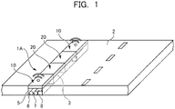
FIG. 1 is a diagram schematically illustrating a housing unit according to a first embodiment of the present invention and a road where the housing unit is installed; -
FIG. 2 is a schematic diagram illustrating a wireless communication system including a wireless communication device according to the first embodiment; -
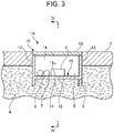
FIG. 3 is a front cross-sectional view of the housing unit according to the first embodiment, taken along arrows III-III inFIG. 4 ; -
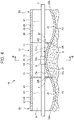
FIG. 4 is a cross-sectional view taken along arrows IV-IV inFIG. 3 ; -
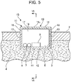
FIG. 5 is a front cross-sectional view of a housing unit according to a second embodiment of the present invention, taken along arrows V-V inFIG. 6 ; -
FIG. 6 is a cross-sectional view taken along arrows VI-VI inFIG. 5 ; -
FIG. 7 illustrates a first modification of the first embodiment, and is a side cross-sectional view of a first resin container; -
FIG. 8 illustrates a second modification of the first embodiment, and is a side cross-sectional view of a first resin container; and -
FIG. 9 illustrates a third modification of the first embodiment, and is a side cross-sectional view of a first resin container. - Embodiments of the present invention will be described below with reference to the drawings.
FIG. 1 is a diagram schematically illustrating ahousing unit 1A according to the present invention. Thehousing unit 1A includes resin containers for housing cables. The cables include, for example, a power transmission cable (apower line 7 to be described later) that transmits electric power to households, etc., and a communication transmission cable (acommunication line 6 to be described later) that transmits information. Thehousing unit 1A includes a pluralityfirst resin containers 10 that have a polygonal tubular shape and are arranged at predetermined intervals in agutter 3 of aroad 2, and a plurality ofsecond resin containers 20 that have a polygonal tubular shape and are disposed between thefirst resin containers 10. As will be described in detail later, thefirst resin container 10 houses a wireless base station to which the cables are connected. Thehousing unit 1A is laid such that eachfirst resin container 10 is disposed at a location where the wireless base station is to be installed and eachsecond resin container 20 is disposed in front of or behind the associatedfirst resin container 10 in a direction in which the cables extend (on one side or the opposite side of thefirst resin container 10 in the direction in which the cables extend). - The
housing unit 1A may also include one or more third resin containers (not illustrated). The third resin container has a bottom and a lid that are substantially horizontal (flat) and is not provided with a drain portion or a drain water-receiving portion that will be described in detail later. In thehousing unit 1A having this configuration, onesecond resin container 20 is disposed while having its one end positioned in front of or behind the associatedfirst resin container 10 in the direction in which the cables extend, and one third resin container 30 is disposed while having its one end positioned adjacent to the other end of the onesecond resin container 20. In a case where thehousing unit 1A includes onefirst resin container 10 and a nextfirst resin container 10 that are arranged with a large spacing therebetween, two or more third resin containers are arranged adjacent to each other between onesecond resin container 20 disposed in front of or behind the onefirst resin container 10 and a nextsecond resin container 20 disposed in front of or behind the nextfirst resin container 10. - The plurality of
resin containers underground space 5 is formed inside the plurality ofresin containers underground space 5, the cables (thecommunication line 6 and thepower line 7 illustrated inFIG. 1 ) are laid. - Each
first resin container 10 houses awireless base station 8. In other words, a plurality ofwireless base stations 8 are distributed at regular intervals along thegutter 3. Thewireless base station 8 is an example of a wireless communication device according to the present invention, and is a device that transmits and receives communication radio waves to and from mobile communication terminals, such as cell phones. Thewireless base station 8 is, for example, a base station for 5G (the fifth generation mobile communication system), but is not limited to the base station for 5G. For example, thefirst resin containers 10 are arranged at positions where thewireless base stations 8 housed in thefirst resin containers 10 complement each other in terms of the wireless transmission/reception range. - As illustrated in
FIG. 2 , thewireless base station 8 has abody 8a and anantenna 8b. Thebody 8a of thewireless base station 8 housed in thefirst resin container 10 is connected to thecommunication line 6 via acommunication branch line 6a and to thepower line 7 via apower branch line 7a. Thecommunication line 6 is connected to a base station body (exchange) 9. Thewireless base stations 8 are connected to the base station body 9 via thecommunication branch lines 6a and thecommunication line 6. The above-mentioned mobile communication terminals are wirelessly and communicatively connected to the base station body 9 via thewireless base stations 8. Thewireless base stations 8 are supplied with drive power from thepower line 7 via thepower branch lines 7a. - The first embodiment of the
housing unit 1A will be described below. Note that the drawings that will be referred to in the following description illustrate thewireless base station 8 in such a manner that theantenna 8b, which is illustrated inFIG. 2 , is omitted while thebody 8a is illustrated as thewireless base station 8. - As illustrated in
FIGS. 3 and4 , thehousing unit 1A according to the first embodiment includes afirst resin container 10 having a polygonal tubular shape and housing thewireless base station 8, andsecond resin containers 20 disposed adjacent to the two opposing ends of thefirst resin container 10. Thefirst resin container 10 and thesecond resin containers 20 are arranged in agutter 3 of aroad 2 and are buried in theground 4, as illustrated inFIG. 1 . As described above, the interior spaces of theresin containers underground space 5 in which acommunication line 6 and apower line 7 are laid. - The
first resin container 10 has afirst container body 11 and afirst lid 16. Thefirst container body 11 and thefirst lid 16 are each a one-piece molding made of a predetermined resin material. - The
first container body 11 has the shape of a so-called U-shaped groove and has a first bottom 12, a pair ofside walls first opening 14 that opens upward. - As illustrated in
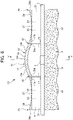
FIG. 4 , the first bottom 12 has oneend 12a and theother end 12b that face the adjacentsecond resin containers 20, respectively. The first bottom 12 has the shape of an arch that curves upward convexly throughout from the oneend 12a to theother end 12b. The first bottom 12 has adrain portion 15 on its upper surface. - The
drain portion 15 has acrest 15c that is the highest part of thedrain portion 15, acurved surface 15a that gradually decreases in height throughout from thecrest 15c to the oneend 12a, and acurved surface 15b that gradually decreases in height throughout from thecrest 15c to theother end 12b. Thecurved surfaces crest 15c to the oneend 12a and theother end 12b, respectively, while constantly decreasing in height. Thecurved surfaces - As illustrated in
FIG. 4 , thewireless base station 8 is disposed on thecrest 15c of thedrain portion 15. Thewireless base station 8 is held stably on thecrest 15c using a fastening member such as a fixing device or a screw. - The
first lid 16 is a plate-like member that closes thefirst opening 14 of thefirst container body 11. Thefirst lid 16 is made of a resin having radio wave permeability. Thefirst lid 16 is detachably attached to thefirst container body 11 using a fastening means such as a metal fastener or a rubber band. - As illustrated in
FIG. 4 , thesecond resin containers 20 are disposed adjacent to the two opposing ends of thefirst resin container 10 and each include asecond container body 21 and asecond lid 26. Thesecond container body 21 and thesecond lid 26 are each a one-piece molding made of a predetermined resin material. - The
second container body 21 has the shape of a so-called U-shaped groove and has a second bottom 22, a pair ofside walls 23, 23 (only one of which is illustrated inFIG. 4 ), and asecond opening 24 that opens upward. The second bottom 22 has oneend 22a and theother end 22b that face the adjacentfirst resin container 10. - The second bottom 22 curves concavely throughout from the one
end 22a to theother end 22b. The second bottom 22 has a drain water-receivingportion 25 on its upper surface. The drain water-receivingportion 25 has a concave shape to receive water (drain water) flowing down from thedrain portion 15 of thefirst resin container 10. The drain water-receivingportion 25 is constituted by the upper surface of the second bottom 22 that curves concavely. - The
second lid 26 is a plate-like member that closes thesecond opening 24 of thesecond container body 21. Thesecond lid 26 is detachably attached to thesecond container body 21 using a fastening means such as a metal fastener or a rubber band. - The
housing unit 1A according to the first embodiment is arranged in thegutter 3 illustrated inFIG. 1 such that thesecond resin containers 20 are disposed adjacent to the two opposing ends of thefirst resin container 10. Thefirst resin container 10 and thesecond resin containers 20 are disposed adjacent to each other such that each of the opposing ends of one container faces a corresponding one of the opposing ends of the adjacent container. Thefirst resin container 10 and thesecond resin containers 20 may be connected to each other with joint members. - As illustrated in
FIG. 4 , thehousing unit 1A according to the first embodiment has aboundary portion 31 between theend 12a of thefirst bottom 12 of thefirst resin container 10 and theend 22b of thesecond bottom 22 of thesecond resin container 20. Further, thehousing unit 1A has aboundary portion 32 between theend 12b of thefirst bottom 12 of thefirst resin container 10 and theend 22a of thesecond bottom 22 of thesecond resin container 20. - The
crest 15c of thedrain portion 15 of thefirst resin container 10 is at a height greater than the height of theboundary portion 31 and the height of theboundary portion 32. Thecurved surfaces drain portion 15 gradually decrease in height throughout from thecrest 15c to theboundary portion 31 and theboundary portion 32, respectively. The drain water-receivingportions 25 of thesecond resin containers 20 are at a height less than those of theboundary portions curved surfaces drain portion 15 and reached theboundary portions boundary portions portions 25. - Effects exerted by the
housing unit 1A according to the first embodiment are described below. Thehousing unit 1A according to the first embodiment includes the tubularfirst resin container 10 configured to be buried in theground 4 and to house thewireless base station 8, and the tubularsecond resin containers 20 configured to be buried in theground 4 and to be disposed adjacent to thefirst resin container 10, and having the interior spaces communicating with the interior space of thefirst resin container 10. Thefirst resin container 10 includes thedrain portion 15 having thecrest 15c that is at a height greater than the height of theboundary portions first resin container 10 and thesecond resin containers 20, and thecurved surfaces crest 15c to theboundary portions second resin container 20 has the drain water-receivingportion 25 that is at a height less than the height of theboundary portions drain portion 15. - Specifically, the
first resin container 10 includes thefirst container body 11 having the first bottom 12 and thefirst opening 14 that opens upward, and includes thefirst lid 16 closing thefirst opening 14 of thefirst container body 11. Thesecond resin containers 20 each include thesecond container body 21 having the second bottom 22 and thesecond opening 24 that opens upward, and includes thesecond lid 26 closing thesecond opening 24 of thesecond container body 21. Theboundary portions second bottoms 22. The first bottom 12 has thedrain portion 15, and each second bottom 22 has the drain water-receivingportion 25 that receives drain water from thedrain portion 15. Thewireless base station 8 is placed on thecrest 15c of thedrain portion 15 of thefirst resin container 10. - According to the first embodiment, when water, such as rainwater, passes between the
first container body 11 and thefirst lid 16 of thefirst resin container 10 and enters thefirst container body 11, the water flows down the inner surfaces of theside walls 13 to reach thedrain portion 15 on thefirst bottom 12. After reaching thedrain portion 15, the water flows down thecurved surface boundary portion second resin container 20. The water that has been drained into thesecond resin containers 20 flows into the drain water-receivingportion 25 to be stored there. Part of the water passes through theboundary portions ground 4, without crossing theboundary portions - Water that has entered the
first resin container 10 is always drained from thedrain portion 15 to the drain water-receivingportions 25 of thesecond resin containers 20, thereby preventing or reducing the accumulation of water in thefirst resin container 10. Thus, according to the first embodiment, thefirst resin container 10 in which thewireless base station 8 is housed has sufficient drainage, and is effective in making it unlikely for thewireless base station 8 to be submerged in water in thefirst resin container 10. - The
first resin container 10 and thesecond resin containers 20 of the present embodiment may have one or more holes in therespective side wall 13 andside wall 26, or the respective bottom 12 and bottom 22. In that case, the holes also allow water that has entered thefirst resin container 10 and thesecond resin containers 20 to be discharged to the outside (into the ground 4). - Next, a
housing unit 1B according to a second embodiment of the present invention will be described with reference toFIGS. 5 and6 . In the drawings that will be referred to in the description of the second embodiment, the same elements as those of the first embodiment are denoted by the same reference characters. A description of the same elements will be omitted, while differences from the first embodiment will be described. - As shown in
FIGS. 5 and6 , afirst resin container 10 according to the second embodiment includes acontainer body 11 having a flat bottom 12, andsecond resin containers 20 according to the second embodiment each include acontainer body 21 having aflat bottom 22. The first bottom 12 does not have thedrain portion 15 and the second bottom 22 does not have the drain water-receivingportion 25. Awireless base station 8 is placed on the flat first bottom 12. - As illustrated in
FIG. 5 , thefirst resin container 10 according to the second embodiment has afirst lid 16 that includes atop plate 17 and a pair ofside walls 18. As illustrated inFIG. 6 , thetop plate 17 has oneend 17a and theother end 17b that face the adjacentsecond resin containers 20, respectively. Thetop plate 17 of thefirst lid 16 has the shape of an arch that curves upward convexly throughout from the oneend 17a to theother end 17b. Thetop plate portion 17 has adrain portion 19 on its upper surface. - The
drain portion 19 has acrest 19c that is the highest part, acurved surface 19a that gradually decreases in height throughout from thecrest 19c to the oneend 17a, and acurved surface 19b that gradually decreases in height throughout from thecrest 19c to theother end 17b. Thecurved surfaces crest 19c to the oneend 17a and theother end 17b, respectively, while constantly decreasing in height. Thecurved surfaces - As shown in
FIG. 6 , eachsecond resin container 20 according to the second embodiment has asecond lid 26 having oneend 26a and theother end 26b that face the adjacentfirst resin container 10. Thesecond lid 26 has an upper surface that curves concavely throughout from the oneend 26a to theother end 26b. Thesecond lid 26 has a drain water-receivingportion 27 on its upper surface. - The drain water-receiving
portion 27 is a concave portion that receives water (drain water) flowing down from thedrain portion 19 of thefirst lid 16 of thefirst resin container 10. The drain water-receivingportion 27 is constituted by the upper surface of thesecond lid 26 that curves concavely. - The
housing unit 1B according to the second embodiment has aboundary portion 41 between theend 17a of thetop plate 17 forming part of thefirst lid 16 of thefirst resin container 10 and theend 26b of thesecond lid 26 of thesecond resin container 20. Further, thehousing unit 1B has aboundary portion 42 between theend 17b of thetop plate 17 forming part of thefirst lid 16 of thefirst resin container 10 and theend 26a of thesecond lid 26 of thesecond resin container 20. - The
crest 19c of thedrain portion 19 of thefirst resin container 10 is at a height greater than the height of theboundary portion 41 and the height of theboundary portion 42. Thecurved surface 19a and thecurved surface 19b of thedrain portion 19 gradually decrease in height throughout from thecrest 19c to theboundary portion 41 and theboundary portion 42, respectively. The drain water-receivingportions 27 of thesecond resin containers 20 are at a height less than those of theboundary portions curved surfaces drain portion 19 and reached theboundary portions boundary portions portions 27. - Effects exerted by the
housing unit 1B according to the second embodiment are described below. In thehousing unit 1B according to the second embodiment, thefirst resin container 10 includes thefirst container body 11 having the first bottom 12 and thefirst opening 14 that opens upward, and includes thefirst lid 16 closing thefirst opening 14 of thefirst container body 11. Thesecond resin containers 20 each include thesecond container body 21 having the second bottom 22 and thesecond opening 24 that opens upward, and includes thesecond lid 26 closing thesecond opening 24 of thesecond container body 21. Theboundary portion 41 and theboundary portion 42 are provided between thefirst lid 16 and thesecond lids 26. Thefirst lid 16 has thedrain portion 19, and eachsecond lid 26 has the drain water-receivingportion 27 that receives drain water from thedrain portion 19. - According to the second embodiment, when it is raining, for example, the
drain portion 19 on thefirst lid 16 receives rainwater. The rainwater or other water received by thedrain portion 19 flows down thecurved surfaces boundary portions second lids 26 of thesecond resin containers 20, and then, flows into the drain water-receivingportions 27 to be stored there. Part of the water falls through gaps between thefirst lid 16 of thefirst resin container 10 and thesecond lids 26 of thesecond resin containers 20 without crossing theboundary portions ground 4. - As can be seen, water falling onto the
first lid 16 of thefirst resin container 10 is drained from thedrain portion 19 of thefirst resin container 10 to the drain water-receivingportions 27 of thesecond resin containers 20, thereby reducing or preventing the accumulation of water in thefirst resin container 10. Thus, according to the second embodiment, thefirst resin container 10 in which thewireless base station 8 is housed has sufficient drainage, and is effective in making it unlikely for thewireless base station 8 to be submerged in water in thefirst resin container 10. - Accumulation of water on the
first lid 16 may cause a change in permittivity and affect the radio wave characteristics transmitted and received by thewireless base station 8 installed below thefirst lid 16. To address this, thedrain portion 19 of the second embodiment can prevent water from accumulating above thewireless base station 8. This feature makes it unlikely for puddles to form on thefirst lid 16 even when it rains, and allows stable radio wave characteristics to be obtained. - Next, three modifications (first to third modifications) of the above-described first embodiment will be described with reference to
FIGS. 7 to 9 . The following modifications differ from the first embodiment in the way in which thewireless base station 8 is housed in thefirst resin container 10. -
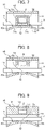
FIG. 7 illustrates the first modification. According to the first modification, thefirst container body 11 of thefirst resin container 10 has asupport 51 that is spaced upwardly from thefirst bottom 12. Thesupport 51 includes a plurality oflegs 51a. Thesupport 51 is fixed to thedrain portion 15 of thefirst bottom 12. On top of thesupport 51, awaterproof case 52 is provided and integrated with thesupport 51. Thewireless base station 8 is housed and sealed in thewaterproof case 52 in a liquid-tight manner. - In the first modification, the
wireless base station 8 is housed in thewaterproof case 52 and supported by thesupport 51 at a position spaced upwardly from thedrain portion 15. This configuration makes it unlikely for thewireless base station 8 to be submerged in water in thefirst container body 11, and can prevent thewireless base station 8 from coming into contact with water that has entered thefirst resin container 10. -
FIG. 8 illustrates the second modification. According to the second modification, awaterproof case 52 that houses thewireless base station 8 is fixed to the back surface of thefirst lid 16. In this modification, thefirst lid 16 forms asupport 51 that is spaced upwardly from thefirst bottom 12. - In the second modification, the
wireless base station 8 is supported at a position spaced upwardly from thedrain portion 15 by being housed in thewaterproof case 52 fixed to the back surface of thefirst lid 16. This configuration makes it unlikely for thewireless base station 8 to be submerged in water in thefirst container body 11, and can prevent thewireless base station 8 from coming into contact with water that has entered thefirst resin container 10. In addition, since thefirst lid 16 also serves as the support by which thewireless base station 8 is spaced upwardly from the first bottom 12, thesupport 51 as in the first modification described above can be omitted, thereby reducing an increase in the number of the components. -
FIG. 9 illustrates the third modification. Thefirst lid 16 of the third modification has ahousing chamber 53 that opens upward. Thehousing chamber 53 is liquid-tightly sealed with alid part 54 that is detachably attached to thefirst lid 16. Thewireless base station 8 is housed in thehousing chamber 53. - According to the third modification, the
wireless base station 8 is housed in thehousing chamber 53 of thefirst lid 16 in a liquid-tight manner. This configuration makes it unlikely for thewireless base station 8 to be submerged in water in thefirst container body 11, and can prevent thewireless base station 8 from coming into contact with water that has entered thefirst resin container 10. - It should be noted that the above-described embodiments and modifications of the present invention are not intended to limit the present invention, and appropriate variations may be made to the present invention. For example, the
container bodies FIGS. 7 to 9 may be applied to the second embodiment. -
- 1A, 1B:
- Housing unit
- 4:
- Ground
- 6:
- Communication line (Cable)
- 7:
- Power line (Cable)
- 8:
- Wireless base station (Wireless communication device)
- 10:
- First resin container
- 11:
- First container body
- 12:
- First bottom
- 14:
- First opening
- 15, 19:
- Drain portion
- 15a, 15b, 19a, 19b:
- Curved surface (Height varying portion)
- 15c, 19c:
- Crest
- 16:
- First lid
- 20:
- Second resin container
- 21:
- Second container body
- 22:
- Second bottom
- 24:
- Second opening
- 25, 27:
- Drain water- receiving portion
- 26:
- Second lid
- 31, 32, 41, 42:
- Boundary portion
- 51:
- Support
- 52:
- Waterproof case
- 53:
- Housing chamber
Claims (6)
- A housing unit comprising resin containers for housing a cable,
the resin containers comprising:a first resin container configured to house a wireless communication device to which the cable is connected; anda second resin container configured to be disposed in front of or behind the first resin container in a direction in which the cable extends, and having an interior space that is adapted to communicate with an interior space of the first resin container,the first resin container including a drain portion having a crest and a height varying portion, the crest being at a height greater than that of a boundary portion between the first resin container and the second resin container, the height varying portion decreasing in height throughout from the crest to the boundary portion,the second resin container including a drain water-receiving portion that receives drain water from the drain portion, the drain water-receiving portion being at a height less than that of the boundary portion. - The housing unit according to claim 1, whereinthe first resin container further includes a first container body and a first lid, the first container body having a first bottom and a first opening that opens upward, the first lid closing the first opening of the first container body,the second resin container further includes a second container body and a second lid, the second container body having a second bottom and a second opening that opens upward, the second lid closing the second opening of the second container body,in a state where the second resin container is disposed in front of or behind the first resin container in the direction in which the cable extends, the boundary portion is provided between the first bottom and the second bottom,the first bottom has the drain portion, andthe second bottom has the drain water-receiving portion.
- The housing unit according to claim 1, whereinthe first resin container further includes a first container body and a first lid, the first container body having a first bottom and a first opening that opens upward, the first lid closing the first opening of the first container body,the second resin container further includes a second container body and a second lid, the second container body having a second bottom and a second opening that opens upward, the second lid closing the second opening of the second container body,in a state where the second resin container is disposed in front of or behind the first resin container in the direction in which the cable extends, the boundary portion is provided between the first lid and the second lid,the first lid has the drain portion, andthe second lid has the drain water-receiving portion.
- The housing unit according to claim 2, wherein
the wireless communication device is placed on the crest of the drain portion. - The housing unit according to claim 2 or 3, whereinthe first resin container further includes a support that is spaced upwardly from the first bottom, andthe wireless communication device is supported by the support while being housed in a waterproof case.
- The housing unit according to claim 2 or 3, whereinthe first lid has a housing chamber configured to house and seal the wireless communication device in a liquid-tight manner, andthe wireless communication device is housed in the housing chamber.
Applications Claiming Priority (2)
| Application Number | Priority Date | Filing Date | Title |
|---|---|---|---|
| JP2019197200 | 2019-10-30 | ||
| PCT/JP2020/040922 WO2021085626A1 (en) | 2019-10-30 | 2020-10-30 | Housing unit |
Publications (2)
| Publication Number | Publication Date |
|---|---|
| EP4053995A1 true EP4053995A1 (en) | 2022-09-07 |
| EP4053995A4 EP4053995A4 (en) | 2023-12-13 |
Family
ID=75715170
Family Applications (1)
| Application Number | Title | Priority Date | Filing Date |
|---|---|---|---|
| EP20881540.7A Withdrawn EP4053995A4 (en) | 2019-10-30 | 2020-10-30 | Housing unit |
Country Status (5)
| Country | Link |
|---|---|
| US (1) | US20220231398A1 (en) |
| EP (1) | EP4053995A4 (en) |
| JP (1) | JPWO2021085626A1 (en) |
| AU (1) | AU2020375372A1 (en) |
| WO (1) | WO2021085626A1 (en) |
Families Citing this family (1)
| Publication number | Priority date | Publication date | Assignee | Title |
|---|---|---|---|---|
| JP2022061780A (en) * | 2020-10-07 | 2022-04-19 | 古河電気工業株式会社 | Resin container |
Family Cites Families (15)
| Publication number | Priority date | Publication date | Assignee | Title |
|---|---|---|---|---|
| JP2790975B2 (en) * | 1993-09-24 | 1998-08-27 | 関西電力株式会社 | Transmission equipment used for monitoring of human holes |
| JPH08296271A (en) * | 1995-04-24 | 1996-11-12 | Morishita Kagaku Kogyo Kk | Drainage storage device for removing invading solids in underground boxes |
| JP3936864B2 (en) * | 2001-12-28 | 2007-06-27 | 川田建設株式会社 | Cable storage duct device |
| JP2003258692A (en) * | 2002-02-27 | 2003-09-12 | Aron Kasei Co Ltd | Information transmission device using optical fiber cable and wireless device |
| US8835757B2 (en) * | 2010-11-10 | 2014-09-16 | Oldcastle Precast, Inc. | Locking subgrade vault |
| US9001002B2 (en) * | 2011-09-30 | 2015-04-07 | Apple Inc. | Portable electronic device housing having insert molding around antenna |
| US9287693B2 (en) * | 2012-10-30 | 2016-03-15 | Channell Commercial Corporation | Enhanced strength grade level utilities enclosure |
| US10924149B2 (en) * | 2016-11-22 | 2021-02-16 | Telefonaktiebolaget Lm Ericsson (Publ) | Underground base station |
| JP6551755B2 (en) * | 2017-02-09 | 2019-07-31 | パナソニックIpマネジメント株式会社 | Control method of power transmission device in wireless power transmission system, and power transmission device |
| JP2019035307A (en) * | 2017-08-22 | 2019-03-07 | エバタ株式会社 | System for storing and infiltrating rainwater and for eliminating electric pole |
| EP3660978B1 (en) | 2017-08-24 | 2022-09-28 | Ntt Docomo, Inc. | Antenna device, wireless base station, and antenna device container |
| CN107516866A (en) * | 2017-08-30 | 2017-12-26 | 国家电网公司 | A kind of Prefabricated cable duct |
| JP2020014308A (en) * | 2018-07-17 | 2020-01-23 | 未来工業株式会社 | Trough buried structure and common ditch |
| CN110943419B (en) * | 2019-11-22 | 2021-04-30 | 河北瑞池工程项目管理有限公司 | a cable trench |
| CN111779028A (en) * | 2020-07-04 | 2020-10-16 | 四川航天建筑工程有限公司 | A kind of finished product prefabricated electric power shallow trench and its construction method |
-
2020
- 2020-10-30 EP EP20881540.7A patent/EP4053995A4/en not_active Withdrawn
- 2020-10-30 WO PCT/JP2020/040922 patent/WO2021085626A1/en not_active Ceased
- 2020-10-30 JP JP2021553736A patent/JPWO2021085626A1/ja active Pending
- 2020-10-30 AU AU2020375372A patent/AU2020375372A1/en not_active Abandoned
-
2022
- 2022-04-05 US US17/657,969 patent/US20220231398A1/en not_active Abandoned
Also Published As
| Publication number | Publication date |
|---|---|
| AU2020375372A1 (en) | 2022-06-09 |
| EP4053995A4 (en) | 2023-12-13 |
| US20220231398A1 (en) | 2022-07-21 |
| WO2021085626A1 (en) | 2021-05-06 |
| JPWO2021085626A1 (en) | 2021-05-06 |
Similar Documents
| Publication | Publication Date | Title |
|---|---|---|
| US10629980B2 (en) | Wireless distribution using cabinets, pedestals, and hand holes | |
| US20220231398A1 (en) | Housing unit | |
| CN104160103B (en) | Storage tank thermal insulation joint device and method | |
| WO2010090755A2 (en) | Stormwater management system | |
| WO2021085625A1 (en) | Wireless communication structure | |
| CN109162339A (en) | A kind of assembled architecture embedding pipe fittings | |
| KR100711607B1 (en) | Construction roof leak prevention facility structure | |
| EP3651267B1 (en) | Cover element with transmitter system | |
| EP0468881B1 (en) | Service hookup terminal | |
| JP2021082919A (en) | Water level measurement system, water level meter, and water level measurement method | |
| JP2016079661A (en) | Backflow prevention device for sewage basin | |
| KR100463225B1 (en) | Water channel block | |
| AU2021206525B2 (en) | Drainage system | |
| KR100823556B1 (en) | Storm receiver installed on the foundation of transmission tower | |
| CN218263455U (en) | River-crossing bridge water-drainage preventing system with flood level higher than design elevation of bridge deck | |
| KR20190093854A (en) | Mobile antenna camouflage device | |
| CN218374031U (en) | Anti-sedimentation water supply well | |
| CN223991384U (en) | Sealed waterproof intelligent water meter well | |
| CN223317242U (en) | A seepage prevention device for springs in high-latitude and cold regions | |
| JP4931087B2 (en) | Drain hose connection fitting | |
| KR20200079038A (en) | Waterproof structure to prevent flooding of houses entrance using buoyancy | |
| KR200287471Y1 (en) | Water channel block | |
| KR100770753B1 (en) | Watertight Structure of Sewer Support Frame | |
| CN207892007U (en) | A kind of mutual buckle type gully | |
| KR200261604Y1 (en) | assembly type manhole structure |
Legal Events
| Date | Code | Title | Description |
|---|---|---|---|
| STAA | Information on the status of an ep patent application or granted ep patent |
Free format text: STATUS: THE INTERNATIONAL PUBLICATION HAS BEEN MADE |
|
| PUAI | Public reference made under article 153(3) epc to a published international application that has entered the european phase |
Free format text: ORIGINAL CODE: 0009012 |
|
| STAA | Information on the status of an ep patent application or granted ep patent |
Free format text: STATUS: REQUEST FOR EXAMINATION WAS MADE |
|
| 17P | Request for examination filed |
Effective date: 20220503 |
|
| AK | Designated contracting states |
Kind code of ref document: A1 Designated state(s): AL AT BE BG CH CY CZ DE DK EE ES FI FR GB GR HR HU IE IS IT LI LT LU LV MC MK MT NL NO PL PT RO RS SE SI SK SM TR |
|
| DAV | Request for validation of the european patent (deleted) | ||
| DAX | Request for extension of the european patent (deleted) | ||
| A4 | Supplementary search report drawn up and despatched |
Effective date: 20231113 |
|
| RIC1 | Information provided on ipc code assigned before grant |
Ipc: H01Q 1/42 20060101ALI20231107BHEP Ipc: H04B 1/38 20150101ALI20231107BHEP Ipc: H01Q 1/04 20060101AFI20231107BHEP |
|
| STAA | Information on the status of an ep patent application or granted ep patent |
Free format text: STATUS: THE APPLICATION HAS BEEN WITHDRAWN |
|
| 18W | Application withdrawn |
Effective date: 20240528 |