EP4053990A1 - Battery module comprising module bus bar, battery pack comprising same, and electronic device - Google Patents
Battery module comprising module bus bar, battery pack comprising same, and electronic device Download PDFInfo
- Publication number
- EP4053990A1 EP4053990A1 EP21785020.5A EP21785020A EP4053990A1 EP 4053990 A1 EP4053990 A1 EP 4053990A1 EP 21785020 A EP21785020 A EP 21785020A EP 4053990 A1 EP4053990 A1 EP 4053990A1
- Authority
- EP
- European Patent Office
- Prior art keywords
- metal plate
- module
- battery
- body portion
- bus bar
- Prior art date
- Legal status (The legal status is an assumption and is not a legal conclusion. Google has not performed a legal analysis and makes no representation as to the accuracy of the status listed.)
- Granted
Links
Images



Classifications
-
- H—ELECTRICITY
- H01—ELECTRIC ELEMENTS
- H01M—PROCESSES OR MEANS, e.g. BATTERIES, FOR THE DIRECT CONVERSION OF CHEMICAL ENERGY INTO ELECTRICAL ENERGY
- H01M50/00—Constructional details or processes of manufacture of the non-active parts of electrochemical cells other than fuel cells, e.g. hybrid cells
- H01M50/20—Mountings; Secondary casings or frames; Racks, modules or packs; Suspension devices; Shock absorbers; Transport or carrying devices; Holders
- H01M50/204—Racks, modules or packs for multiple batteries or multiple cells
- H01M50/207—Racks, modules or packs for multiple batteries or multiple cells characterised by their shape
- H01M50/213—Racks, modules or packs for multiple batteries or multiple cells characterised by their shape adapted for cells having curved cross-section, e.g. round or elliptic
-
- H—ELECTRICITY
- H01—ELECTRIC ELEMENTS
- H01M—PROCESSES OR MEANS, e.g. BATTERIES, FOR THE DIRECT CONVERSION OF CHEMICAL ENERGY INTO ELECTRICAL ENERGY
- H01M50/00—Constructional details or processes of manufacture of the non-active parts of electrochemical cells other than fuel cells, e.g. hybrid cells
- H01M50/50—Current conducting connections for cells or batteries
- H01M50/502—Interconnectors for connecting terminals of adjacent batteries; Interconnectors for connecting cells outside a battery casing
-
- H—ELECTRICITY
- H01—ELECTRIC ELEMENTS
- H01M—PROCESSES OR MEANS, e.g. BATTERIES, FOR THE DIRECT CONVERSION OF CHEMICAL ENERGY INTO ELECTRICAL ENERGY
- H01M50/00—Constructional details or processes of manufacture of the non-active parts of electrochemical cells other than fuel cells, e.g. hybrid cells
- H01M50/50—Current conducting connections for cells or batteries
- H01M50/502—Interconnectors for connecting terminals of adjacent batteries; Interconnectors for connecting cells outside a battery casing
- H01M50/507—Interconnectors for connecting terminals of adjacent batteries; Interconnectors for connecting cells outside a battery casing comprising an arrangement of two or more busbars within a container structure, e.g. busbar modules
-
- H—ELECTRICITY
- H01—ELECTRIC ELEMENTS
- H01M—PROCESSES OR MEANS, e.g. BATTERIES, FOR THE DIRECT CONVERSION OF CHEMICAL ENERGY INTO ELECTRICAL ENERGY
- H01M50/00—Constructional details or processes of manufacture of the non-active parts of electrochemical cells other than fuel cells, e.g. hybrid cells
- H01M50/50—Current conducting connections for cells or batteries
- H01M50/502—Interconnectors for connecting terminals of adjacent batteries; Interconnectors for connecting cells outside a battery casing
- H01M50/503—Interconnectors for connecting terminals of adjacent batteries; Interconnectors for connecting cells outside a battery casing characterised by the shape of the interconnectors
-
- H—ELECTRICITY
- H01—ELECTRIC ELEMENTS
- H01M—PROCESSES OR MEANS, e.g. BATTERIES, FOR THE DIRECT CONVERSION OF CHEMICAL ENERGY INTO ELECTRICAL ENERGY
- H01M50/00—Constructional details or processes of manufacture of the non-active parts of electrochemical cells other than fuel cells, e.g. hybrid cells
- H01M50/50—Current conducting connections for cells or batteries
- H01M50/502—Interconnectors for connecting terminals of adjacent batteries; Interconnectors for connecting cells outside a battery casing
- H01M50/514—Methods for interconnecting adjacent batteries or cells
- H01M50/516—Methods for interconnecting adjacent batteries or cells by welding, soldering or brazing
-
- H—ELECTRICITY
- H01—ELECTRIC ELEMENTS
- H01M—PROCESSES OR MEANS, e.g. BATTERIES, FOR THE DIRECT CONVERSION OF CHEMICAL ENERGY INTO ELECTRICAL ENERGY
- H01M50/00—Constructional details or processes of manufacture of the non-active parts of electrochemical cells other than fuel cells, e.g. hybrid cells
- H01M50/50—Current conducting connections for cells or batteries
- H01M50/502—Interconnectors for connecting terminals of adjacent batteries; Interconnectors for connecting cells outside a battery casing
- H01M50/514—Methods for interconnecting adjacent batteries or cells
- H01M50/517—Methods for interconnecting adjacent batteries or cells by fixing means, e.g. screws, rivets or bolts
-
- H—ELECTRICITY
- H01—ELECTRIC ELEMENTS
- H01M—PROCESSES OR MEANS, e.g. BATTERIES, FOR THE DIRECT CONVERSION OF CHEMICAL ENERGY INTO ELECTRICAL ENERGY
- H01M50/00—Constructional details or processes of manufacture of the non-active parts of electrochemical cells other than fuel cells, e.g. hybrid cells
- H01M50/50—Current conducting connections for cells or batteries
- H01M50/572—Means for preventing undesired use or discharge
- H01M50/574—Devices or arrangements for the interruption of current
- H01M50/581—Devices or arrangements for the interruption of current in response to temperature
-
- H—ELECTRICITY
- H01—ELECTRIC ELEMENTS
- H01M—PROCESSES OR MEANS, e.g. BATTERIES, FOR THE DIRECT CONVERSION OF CHEMICAL ENERGY INTO ELECTRICAL ENERGY
- H01M50/00—Constructional details or processes of manufacture of the non-active parts of electrochemical cells other than fuel cells, e.g. hybrid cells
- H01M50/50—Current conducting connections for cells or batteries
- H01M50/572—Means for preventing undesired use or discharge
- H01M50/574—Devices or arrangements for the interruption of current
- H01M50/583—Devices or arrangements for the interruption of current in response to current, e.g. fuses
-
- H—ELECTRICITY
- H01—ELECTRIC ELEMENTS
- H01M—PROCESSES OR MEANS, e.g. BATTERIES, FOR THE DIRECT CONVERSION OF CHEMICAL ENERGY INTO ELECTRICAL ENERGY
- H01M2200/00—Safety devices for primary or secondary batteries
- H01M2200/10—Temperature sensitive devices
- H01M2200/103—Fuse
-
- H—ELECTRICITY
- H01—ELECTRIC ELEMENTS
- H01M—PROCESSES OR MEANS, e.g. BATTERIES, FOR THE DIRECT CONVERSION OF CHEMICAL ENERGY INTO ELECTRICAL ENERGY
- H01M2220/00—Batteries for particular applications
- H01M2220/20—Batteries in motive systems, e.g. vehicle, ship, plane
-
- Y—GENERAL TAGGING OF NEW TECHNOLOGICAL DEVELOPMENTS; GENERAL TAGGING OF CROSS-SECTIONAL TECHNOLOGIES SPANNING OVER SEVERAL SECTIONS OF THE IPC; TECHNICAL SUBJECTS COVERED BY FORMER USPC CROSS-REFERENCE ART COLLECTIONS [XRACs] AND DIGESTS
- Y02—TECHNOLOGIES OR APPLICATIONS FOR MITIGATION OR ADAPTATION AGAINST CLIMATE CHANGE
- Y02E—REDUCTION OF GREENHOUSE GAS [GHG] EMISSIONS, RELATED TO ENERGY GENERATION, TRANSMISSION OR DISTRIBUTION
- Y02E60/00—Enabling technologies; Technologies with a potential or indirect contribution to GHG emissions mitigation
- Y02E60/10—Energy storage using batteries
Definitions
- the present disclosure relates to a battery module including a module bus bar, a battery pack including the battery module, and an electronic device, and more particularly, to a battery module including a module bus bar that may make an electrical disconnection rapidly when a high current flows and has excellent durability.
- Secondary batteries currently commercialized include nickel cadmium batteries, nickel hydrogen batteries, nickel zinc batteries, lithium secondary batteries and so on.
- the lithium secondary batteries are more highlighted in comparison to nickel-based secondary batteries due to advantages such as free charging and discharging, caused by substantially no memory effect, very low self-discharge rate, and high energy density.
- the lithium secondary battery mainly uses lithium-based oxides and carbonaceous materials as a positive electrode active material and a negative electrode active material, respectively.
- the lithium secondary battery includes an electrode assembly in which a positive electrode plate coated with the positive electrode active material and a negative electrode plate coated with the negative electrode active material are disposed with a separator being interposed therebetween, and an exterior, namely a battery case, hermetically containing the electrode assembly together with an electrolyte.
- the lithium secondary battery may be classified depending on the exterior shape into a can-type secondary battery in which an electrode assembly is included in a metal can and a pouch-type secondary battery in which an electrode assembly is included in a pouch made of an aluminum laminate sheet.
- the metal can in which the electrode assembly is included is sometimes manufactured in a cylindrical shape.
- the can-type secondary battery may be used to configure a battery module having a housing for accommodating a plurality of secondary batteries and a bus bar for electrically connecting the plurality of secondary batteries.
- the bus bar provided to the battery module uses a material having a somewhat high electrical resistance in order to increase the weldability of resistance welding with the electrode terminal.
- a battery management system may be used to cut off the current.
- a fuse that is disconnected when a high current flows may be applied as a part of the bus bar.
- the fuse of the bus bar is formed to have a smaller thickness or width than the other part of the bus bar in order to set the electrical resistance larger.
- the fuse of the bus bar having a smaller thickness or width has relatively weak mechanical stiffness. Thus, if an external shock or frequent vibrations are applied to the battery module, the fuse may be disconnected due to damage or cutting, which may deteriorate the durability of the battery module.
- the present disclosure is designed to solve the problems of the related art, and therefore the present disclosure is directed to providing a battery module including a module bus bar, which may make an electrical disconnection rapidly when a high current flows and has excellent durability.
- a battery module comprising:
- the second metal plate may include a reinforcing portion formed between the second contact portion and the fuse portion and having a greater width than the fuse portion.
- the module housing may include a connection opening perforated so that the electrode terminal of the cylindrical battery cell accommodated in the inner space is exposed to the outside, and a part of the reinforcing portion may be bent into the module housing through the connection opening.
- the reinforcing portion may be bonded to at least one of a rim of the connection opening and a periphery of the connection opening.
- the second metal plate may include a reinforcing member configured to surround a connection region of the fuse portion and the second body portion.
- each of the first metal plate and the second metal plate may have a fixing hole perforated in an upper and lower direction
- the module housing may include a fixing protrusion inserted into the fixing hole to fix each of the first metal plate and the second metal plate, and a cushion member interposed between the fixing hole and the fixing protrusion.
- the second metal plate may have a metal material with a greater specific resistance than the metal material of the first metal plate.
- the fuse portion may be bent at least once based on a direction extending from the second body portion, and the second contact portion may have at least two welding areas arranged in a direction perpendicular to the bending direction of the fuse portion based on a horizontal direction and welded to the electrode terminal.
- a battery pack comprising at least one battery module as above.
- an electronic device comprising the battery pack as above.
- the module bus bar of the present disclosure since the module bus bar of the present disclosure includes the first metal plate and the second metal plate located at the outer side of the first metal plate and having a smaller thickness than the first metal plate, it is possible to improve the durability of the module bus bar. That is, since the relatively thick first metal plate has relatively better rigidity against vibration or impact than the second metal plate, in the configuration where the first body portion of the first metal plate is disposed to face the outer surface of the module housing and the second body portion of the second metal plate having a smaller thickness is disposed at the outer side of the first body portion, it is possible to effectively reduce damage caused by the shock and continuous vibration of the module housing transmitted to the module bus bar.
- the fuse portion is more highly likely to be cut due to its small width in comparison to other regions.
- the second metal plate includes the reinforcing portion provided between the second contact portion and the fuse portion and having a greater width than the fuse portion, it is possible to reinforce mechanical rigidity between the second contact portion and the fuse portion. Therefore, it is possible to further increase the durability of the module bus bar against vibration or impact.
- the fuse portion is bent at least once from the second body portion based on the direction in which the fuse portion extends, and at least two welding areas arranged in a direction perpendicular to the bending direction of the fuse portion based on the horizontal direction and welded to the electrode terminal are formed in the second contact portion.
- the fuse portion is pulled by an external force, the bonded state may be effectively maintained by the strong bonding force of the at least two welding areas arranged in the perpendicular direction. Accordingly, the durability of the battery module may be effectively increased.
- the cushion member may absorb vibrations or shocks transmitted from the module housing to the module bus bar, thereby effectively reducing the damage caused by frequent vibrations and shocks of the module bus bar.
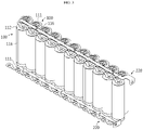
- FIG. 1 is a perspective view schematically showing a battery module according to an embodiment of the present disclosure.
- FIG. 2 is a perspective view schematically showing a module bus bar, which is a component of the battery module according to an embodiment of the present disclosure.
- FIG. 3 is a perspective view schematically showing a plurality of cylindrical battery cells, which are components of the battery module according to an embodiment of the present disclosure.
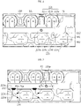
- FIG. 4 is a partial front view schematically showing a portion A of FIG. 1 in an enlarged form.
- a battery module 200 may include a plurality of cylindrical battery cells 100, a module housing 210, and a plurality of module bus bars 220.
- the cylindrical battery cell 100 may include a cylindrical battery can 116, and a battery assembly (not shown) accommodated in the battery can 116.
- the battery can 116 includes a material with high electrical conductivity, and for example, the battery can 116 may include aluminum or copper.
- the battery can 116 may be configured to be laid long in a front and rear direction.
- the battery can 116 may have a cylindrical shape extending in an upper and lower direction.
- electrode terminals 111, 112 may be formed at a front end portion and a rear end of the laid battery can 116.
- the electrode terminals may include a positive electrode terminal 111 and a negative electrode terminal 112.
- the positive electrode terminal 111 may be formed on a flat surface of a front end portion of the battery can 116
- the negative electrode terminal 112 may be formed on a flat circular rear surface of a rear end portion of the battery can 116.
- the positive electrode terminal 111 and the negative electrode terminal 112 may also be provided at the front end portion of the battery can.
- the negative electrode terminal 112 may be located at a rim of the front end portion of the battery can 116, and the positive electrode terminal 111 may be located at the center of the front end portion.
- the positive electrode terminal 111 and the negative electrode terminal 112 formed at the front end portion may be insulated by a gasket that is an electrical insulator.
- the arrangement of the cylindrical battery cell is not necessarily limited there, and conversely, the cylindrical battery cell 100 may be arranged such that the negative electrode terminal 112 is located at the front end portion and the positive electrode terminal 111 is located at the rear end portion.
- a plurality of cylindrical battery cells 100 may be arranged in a left and right direction and in an upper and lower direction. Since the configuration of the cylindrical battery cell 100 is widely known to those skilled in the art at the time of filing of this application, it will not be described in detail in this specification.
- the module housing 210 may have an inner space (not shown) in which the plurality of cylindrical battery cells 100 may be inserted and accommodated.
- the inner space may have a plurality of hollow structures formed to surround an outer surface of the cylindrical battery cell 100.
- the module housing 210 may be made of an electrically insulating material.
- the electrical insulating material may be a polymer plastic. More specifically, the electrical insulating material may be polyvinyl chloride.
- module bus bar 220 may be configured to electrically connect the plurality of cylindrical battery cells 100.
- the plurality of module bus bars 220 may be mounted to a front surface or a rear surface of the module housing 210.
- the module bus bar 220 may include a first metal plate 221 and a second metal plate 223.
- the first metal plate 221 may include a first body portion 221a and a first contact portion 221b.
- the first body portion 221a may be located to face an outer surface of the module housing 210.
- the second metal plate 223 may be stacked on the first body portion 221a of the first metal plate 221.
- the first body portion 221a may be a portion extending in the left and right direction along the outer surface of the module housing 210.
- the first contact portion 221b may be configured to contact the positive electrode terminal 111. That is, at least a part of the first contact portion 221b may be contacted or welded to the positive electrode terminal 111 so as to make an electrical connection with the positive electrode terminal 111.
- the first metal plate 221 may include a connecting portion 221c that connects the first body portion 221a and the first contact portion 221b.
- the connecting portion 221c may have a structure bent inward through the connection opening P1 of the module housing 210.
- the second metal plate 223 may include a second body portion 223a, a second contact portion 223b, and a fuse portion 223c.
- the second body portion 223a may be stacked on an outer side of the first body portion 221a of the first metal plate 221.
- the "outer side” may refer to as an outward direction based on the module housing 210.
- the “inner side” may refer to a direction toward the inner space of the module housing 210.
- the second body portion 223a may have a shape extending flat along the outer surface of the module housing 210.
- the second body portion 223a may be bonded to the first body portion 221a. The bonding may be performed, for example, by high-temperature compression or welding.
- the second contact portion 223b may be configured to contact the electrode terminal 112.
- the electrode terminal 112 in contact with the second contact portion 223b may have an electrical polarity opposite to that of the electrode terminal 111 in contact with the first contact portion 221b.
- the second contact portion 223b may contact the negative electrode terminal 112, and the first contact portion 221b may contact the positive electrode terminal 111.
- both the positive electrode terminal 111 and the negative electrode terminal 112 are provided at the front end portion of the cylindrical battery cell 100, when the fuse portion 223c, explained later, is disconnected, there is a risk that disconnected metal fragments of the fuse portion 223c may electrically connect the positive electrode terminal 111 and the negative electrode terminal 112. Therefore, it is preferable that the second contact portion 223b connected to the fuse portion 223c is in contact with the negative electrode terminal 112.
- the fuse portion 223c may be shaped to electrically connect the second contact portion 223b and the second body portion 223a to each other. That is, one end of the fuse portion 223c may be electrically connected to the second contact portion 223b. The other end of the fuse portion 223c may be connected to the second body portion 223a.
- the fuse portion 223c may have a cross-sectional area set to be disconnected at a predetermined current or higher.
- the fuse portion 223c may be configured such that at least a part of the fuse portion 223c is melted and disconnected by resistance heat when a current of 40A to 60A flows.
- the fuse portion 223c may have a cross-sectional area set in consideration of an allowable current range and a specific resistance of the metal material.
- the second metal plate 223 may have a smaller thickness than that of the first metal plate 221.
- the thickness of the second metal plate 223 may have a ratio of 0.7 to 0.3 based on the first metal plate 221.
- the second metal plate 223 may have a ratio of 0.5 based on the first metal plate 221.
- the first metal plate 221 may have a thickness of 0.3 mm
- the second metal plate 223 may have a thickness of 0.15 mm.
- the module bus bar 220 of the present disclosure since the module bus bar 220 of the present disclosure includes the first metal plate 221 and the second metal plate 223 located at the outer side of the first metal plate 221 and having a smaller thickness than the first metal plate 221, it is possible to improve the durability of the module bus bar 220.
- the relatively thick first metal plate 221 has relatively better rigidity against vibration or impact than the second metal plate 223, in the configuration where the first body portion 221a of the first metal plate 221 is disposed to face the outer surface of the module housing 210 and the second body portion 223a of the second metal plate 223 having a smaller thickness is disposed at the outer side of the first body portion 221a, it is possible to effectively reduce damage caused by the shock and continuous vibration of the module housing 210 transmitted to the module bus bar 220.
- the fuse portion 223c since the second metal plate 223 has a relatively small thickness, it is easy to apply the fuse portion 223c. That is, since the fuse portion 223c may easily have a small cross-sectional area when a thin metal plate is used, the fuse portion 223c may be disconnected in a predetermined current range with high reliability.
- the second metal plate 223 may include a reinforcing portion 223d.
- the reinforcing portion 223d may be provided to reinforce mechanical rigidity of a connection region between the second contact portion 223b and the fuse portion 223c.
- the reinforcing portion 223d may be formed between the second contact portion 223b and the fuse portion 223c.
- the reinforcing portion 223d may have a greater width than that of the fuse portion 223c.
- the fuse portion 223c is more highly likely to be cut due to its small width in comparison to other regions.
- the second metal plate 223 includes the reinforcing portion 223d provided between the second contact portion 223b and the fuse portion 223c and having a greater width than the fuse portion 223c, it is possible to reinforce mechanical rigidity between the second contact portion 223b and the fuse portion 223c. Therefore, it is possible to further increase the durability of the module bus bar 220 against vibration or impact.
- the module housing 210 may have a connection opening P1 perforated so that the electrode terminal of the cylindrical battery cell 100 accommodated in the inner space is exposed to the outside.
- a connection opening P1 perforated so that the electrode terminal of the cylindrical battery cell 100 accommodated in the inner space is exposed to the outside.
- a plurality of connection openings P1 may be provided in each of the front surface and the rear surface of the module housing 210.
- the electrode terminals of the plurality of cylindrical battery cells 100 may be exposed to the outside through the plurality of connection openings P1.
- a part of the reinforcing portion 223d may be bent into the module housing 210 through the connection opening P1.
- the second contact portion (223b) may extend from the bent end of the reinforcing portion 223d in an inner direction of the module housing 210.
- the 'inner direction' refers to a direction in which the inner space of the module housing 210 is located.
- FIG. 5 is a partial front view schematically showing a module bus bar, which is a component of a battery module according to another embodiment of the present disclosure.
- the reinforcing portion 223d may be bonded to at least one of a rim P1a of the connection opening P1 and a periphery P1b of the connection opening P1.
- the 'rim P1a of the connection opening P1' refers to an inner surface of the perforated connection opening P1 of the module housing 210.
- the 'periphery P1b of the connection opening P1' refers to an outer surface of the module housing 210 in contact with the connection opening P1.
- the reinforcing portion 223d may be located at the rim P1a of the connection opening P1 and the periphery P1b of the connection opening P1.
- an adhesive 230 may be applied between the reinforcing portion 223d and the rim P1a and the periphery P1b of the connection opening P1.
- the reinforcing portion 223d may be bonded to the rim P1a and the periphery P1b of the connection opening P1.
- the reinforcing portion 223d is bonded to at least one of the rim P1a of the connection opening P1 and the periphery P1b of the connection opening P1, it is possible to prevent the module bus bar 220 from being damaged as the rim P1a and the periphery P1b of the connection opening P1 of the module housing 210 constantly collides with the reinforcing portion 223d. Moreover, by fixing the reinforcing portion 223d connected to the fuse portion 223c to the module housing 210, it is possible to prevent the fuse portion 223c from being cracked or losing mechanical rigidity as fatigue accumulates due to the continuous vibration of the module housing 210.
- the second metal plate 223 may include the reinforcing member 240 to supplement mechanical rigidity.
- the reinforcing member 240 may be configured to surround the connection region between the fuse portion 223c and the second body portion 223a.
- the reinforcing member 240 may be made of a polymer resin that is cured after application.
- the reinforcing member 240 may have an electrical insulating material.
- the electrical insulating material may be Teflon.
- the reinforcing member 240 may be applied in a molten state (a resin state) to the connection region between the fuse portion 223c and the second body portion 223a and then cured.
- the curing may employ low-temperature curing, ultraviolet curing, or the like.
- the second metal plate 223 includes the reinforcing member 240 configured to surround the connection region between the fuse portion 223c and the second body portion 223a, it is possible to effectively prevent the connection region between the fuse portion 223c and the second body portion 223a from being damaged due to vibration of the battery module 200 or external impact. That is, since the fuse portion 223c having a relatively small width is shaped to extend from the second body portion 223a, if continuous vibration occurs, the connection region between the fuse portion 223c and the second body portion 223a is more highly likely to be disconnected as vibration of the fuse portion 223c becomes more severe. Accordingly, in the present disclosure, the durability of the module bus bar 220 may be further increased by configuring the reinforcing member 240 to surround the connection region between the fuse portion 223c and the second body portion 223a.
- FIG. 6 is a partially sectioned view schematically showing a part of the battery module, taken along the line C-C' of FIG. 5 .
- each of the first metal plate 221 and the second metal plate 223 may have a fixing hole P2 perforated in an upper and lower direction.
- the fixing hole P2 formed in the first metal plate 221 may communicate with the fixing hole P2 formed in the second metal plate 223.
- the module housing 210 may have a fixing protrusion 210p configured to fix each of the first metal plate 221 and the second metal plate 223.
- the fixing protrusion 210p may be configured to be inserted into the fixing hole P2.
- the fixing protrusion 210p protruding on the module housing 210 outward may be inserted into the fixing hole P2 formed in the first metal plate 221 and the fixing hole P2 formed in the second metal plate 223.
- the module housing 210 may have a cushion member 250 interposed between the fixing hole P2 and the fixing protrusion 210p.
- the cushion member 250 may include a material with a predetermined elasticity.
- the cushion member 250 may be made of a urethane material or a rubber material.
- the cushion member 250 may be configured to reduce the degree of transmission of vibrations generated in the module housing 210 to the first metal plate 221 and the second metal plate 223 of the module bus bar 220.
- the cushion member 250 may act to mitigate the shock transmitted to the module bus bar 220.
- the cushion member 250 may absorb vibrations or shocks transmitted from the module housing 210 to the module bus bar 220, thereby effectively reducing the damage caused by frequent vibrations and shocks of the module bus bar 220.
- the second metal plate 223 may have a metal material with a greater specific resistance than the metal material of the first metal plate 221.
- the second metal plate 223 may include, for example, nickel or a nickel alloy.
- the first metal plate 221 may include copper or a copper alloy.
- the fuse portion 223c provided to the second metal plate 223 may be disconnected reliably. That is, since the second metal plate 223 has a greater specific resistance than the first metal plate 221, when the same current flows, the temperature may rise relatively quickly, and thus the fuse portion 223c provided to the second metal plate 223 may be melted and cut faster. Such quick disconnection may be effective in preventing fire or explosion of the battery module 200.
- the fuse portion 223c may have a structure B1 that is bent at least once in a left direction or a right direction based on a direction extending from the second body portion 223a.
- the fuse portion 223c may have a structure B1 bent to the left or right. This bent structure B1 makes it easy to increase the length of a current path of the fuse portion 223c even in a narrow space.
- At least two welding areas W1, W2 welded to the electrode terminal may be formed in the second contact portion 223b.
- a slit S1 may be formed between the at least two welding areas W1, W2.
- the at least two welding areas W1, W2 of the second contact portion 223b may be arranged in a direction perpendicular to the bending direction of the fuse portion 223c based on a horizontal direction.
- the fuse portion 223c may protrude upward from the second body portion 223a, and the protruding end thereof may be bent and extended in a right direction.
- the two welding areas W1, W2 arranged in an upper and lower direction and welded to the electrode terminal 112 may be formed in the second contact portion 223b.
- the fuse portion 223b is bent at least once from the second body portion 223a based on the direction in which the fuse portion 223c extends, and at least two welding areas W1, W2 arranged in a direction perpendicular to the bending direction of the fuse portion 223c based on the horizontal direction and welded to the electrode terminal are formed in the second contact portion 223b.
- the fuse portion 223c is pulled by an external force, the bonded state may be effectively maintained by the strong bonding force (tensile force) of the at least two welding areas W1, W2 arranged in the perpendicular direction. Accordingly, the durability of the battery module 200 may be effectively increased.
- a battery pack (not shown) may include at least one battery module 200.
- the battery pack may further include various devices (not shown) for controlling charging and discharging of the battery module 200, such as a BMS (Battery Management System), a current sensor, a fuse, and the like.
- BMS Battery Management System
- an electronic device includes at least one battery module 200 described above.
- the electronic device may further include a device housing (not shown) having an accommodation space for accommodating the battery module 200, and a display unit by which a user may check a state of charge of the battery module 200.
- the battery pack according to an embodiment of the present disclosure may be included in a vehicle such as an electric vehicle or a hybrid electric vehicle. That is, the battery pack including at least one battery module 200 according to an embodiment of the present disclosure as described above may be mounted in a vehicle body of the vehicle according to an embodiment of the present disclosure.
- Reference Signs 200 battery module 220: module bus bar 221: first metal plate 221a, 221b: first body portion, first contact portion 223: second metal plate 223a, 223b, 223c, 223d: second body portion, second contact portion, fuse portion,reinforcing portion 100: cylindrical battery cell 111, 112: positive electrode terminal, negative electrode terminal B1: bent structure 210: module housing P1: connection opening P1a, P1b: rim, periphery 230: adhesive 240: reinforcing member P2: fixing hole 210p: fixing protrusion 250: cushion member W1, W2: welding area
Landscapes
- Chemical & Material Sciences (AREA)
- Chemical Kinetics & Catalysis (AREA)
- Electrochemistry (AREA)
- General Chemical & Material Sciences (AREA)
- Connection Of Batteries Or Terminals (AREA)
- Battery Mounting, Suspending (AREA)
Abstract
Description
- The present application claims priority to
Korean Patent Application No. 10-2020-0043499 filed on April 9, 2020 - The present disclosure relates to a battery module including a module bus bar, a battery pack including the battery module, and an electronic device, and more particularly, to a battery module including a module bus bar that may make an electrical disconnection rapidly when a high current flows and has excellent durability.
- In recent years, the demand for portable electronic products such as notebooks, video cameras, mobile phones, or the like is rapidly increasing, and the development of electric vehicles, energy storage batteries, robots, satellites, or the like is in earnest. For this reason, high-performance secondary batteries enabling repeated charging and discharging are being actively researched.
- Secondary batteries currently commercialized include nickel cadmium batteries, nickel hydrogen batteries, nickel zinc batteries, lithium secondary batteries and so on. Among them, the lithium secondary batteries are more highlighted in comparison to nickel-based secondary batteries due to advantages such as free charging and discharging, caused by substantially no memory effect, very low self-discharge rate, and high energy density.
- The lithium secondary battery mainly uses lithium-based oxides and carbonaceous materials as a positive electrode active material and a negative electrode active material, respectively. In addition, the lithium secondary battery includes an electrode assembly in which a positive electrode plate coated with the positive electrode active material and a negative electrode plate coated with the negative electrode active material are disposed with a separator being interposed therebetween, and an exterior, namely a battery case, hermetically containing the electrode assembly together with an electrolyte.
- In addition, the lithium secondary battery may be classified depending on the exterior shape into a can-type secondary battery in which an electrode assembly is included in a metal can and a pouch-type secondary battery in which an electrode assembly is included in a pouch made of an aluminum laminate sheet.
- Here, in case of the can-type secondary battery, the metal can in which the electrode assembly is included is sometimes manufactured in a cylindrical shape. The can-type secondary battery may be used to configure a battery module having a housing for accommodating a plurality of secondary batteries and a bus bar for electrically connecting the plurality of secondary batteries.
- Recently, in some cases, the bus bar provided to the battery module uses a material having a somewhat high electrical resistance in order to increase the weldability of resistance welding with the electrode terminal.
- In the prior art, if an electrical short circuit occurs between some secondary batteries among the plurality of secondary batteries included in the battery module so that a high current flows through the bus bar in some secondary batteries, a failure may occur at the product using the battery module. Thus, a battery management system (BMS) may be used to cut off the current. However, in order to cope with the high current when the BMS does not operate or operates erroneously, a fuse that is disconnected when a high current flows may be applied as a part of the bus bar.
- At this time, the fuse of the bus bar is formed to have a smaller thickness or width than the other part of the bus bar in order to set the electrical resistance larger. However, the fuse of the bus bar having a smaller thickness or width has relatively weak mechanical stiffness. Thus, if an external shock or frequent vibrations are applied to the battery module, the fuse may be disconnected due to damage or cutting, which may deteriorate the durability of the battery module.
- The present disclosure is designed to solve the problems of the related art, and therefore the present disclosure is directed to providing a battery module including a module bus bar, which may make an electrical disconnection rapidly when a high current flows and has excellent durability.
- These and other objects and advantages of the present disclosure may be understood from the following detailed description and will become more fully apparent from the exemplary embodiments of the present disclosure. Also, it will be easily understood that the objects and advantages of the present disclosure may be realized by the means shown in the appended claims and combinations thereof.
- In one aspect of the present disclosure, there is provided a battery module, comprising:
- a plurality of cylindrical battery cells having electrode terminals formed therein;
- a module housing having an inner space formed to accommodate the plurality of cylindrical battery cells; and
- a module bus bar configured to electrically connect the plurality of cylindrical battery cells to each other,
- wherein the module bus bar includes:
- a first metal plate having a first body portion located to face an outer surface of the module housing and a first contact portion configured to contact the electrode terminal; and
- a second metal plate having a second body portion stacked on an outer side of the first body portion of the first metal plate, a second contact portion configured to contact the electrode terminal, and a fuse portion configured to electrically connect the second contact portion and the second body portion to each other and be disconnected at a predetermined current or above, the second metal plate having a smaller thickness than the first metal plate.
- Also, the second metal plate may include a reinforcing portion formed between the second contact portion and the fuse portion and having a greater width than the fuse portion.
- Moreover, the module housing may include a connection opening perforated so that the electrode terminal of the cylindrical battery cell accommodated in the inner space is exposed to the outside, and
a part of the reinforcing portion may be bent into the module housing through the connection opening. - In addition, the reinforcing portion may be bonded to at least one of a rim of the connection opening and a periphery of the connection opening.
- Also, the second metal plate may include a reinforcing member configured to surround a connection region of the fuse portion and the second body portion.
- Moreover, each of the first metal plate and the second metal plate may have a fixing hole perforated in an upper and lower direction, and
the module housing may include a fixing protrusion inserted into the fixing hole to fix each of the first metal plate and the second metal plate, and a cushion member interposed between the fixing hole and the fixing protrusion. - In addition, the second metal plate may have a metal material with a greater specific resistance than the metal material of the first metal plate.
- Also, the fuse portion may be bent at least once based on a direction extending from the second body portion, and
the second contact portion may have at least two welding areas arranged in a direction perpendicular to the bending direction of the fuse portion based on a horizontal direction and welded to the electrode terminal. - In another aspect of the present disclosure, there is also provided a battery pack, comprising at least one battery module as above.
- In another aspect of the present disclosure, there is also provided an electronic device, comprising the battery pack as above.
- According to an embodiment of the present disclosure, since the module bus bar of the present disclosure includes the first metal plate and the second metal plate located at the outer side of the first metal plate and having a smaller thickness than the first metal plate, it is possible to improve the durability of the module bus bar. That is, since the relatively thick first metal plate has relatively better rigidity against vibration or impact than the second metal plate, in the configuration where the first body portion of the first metal plate is disposed to face the outer surface of the module housing and the second body portion of the second metal plate having a smaller thickness is disposed at the outer side of the first body portion, it is possible to effectively reduce damage caused by the shock and continuous vibration of the module housing transmitted to the module bus bar.
- Also, according to an embodiment of the present disclosure, if vibration or shock is transmitted to the connection region between the second contact portion and the fuse portion, the fuse portion is more highly likely to be cut due to its small width in comparison to other regions. Thus, since the second metal plate includes the reinforcing portion provided between the second contact portion and the fuse portion and having a greater width than the fuse portion, it is possible to reinforce mechanical rigidity between the second contact portion and the fuse portion. Therefore, it is possible to further increase the durability of the module bus bar against vibration or impact.
- Moreover, according to an embodiment of the present disclosure, the fuse portion is bent at least once from the second body portion based on the direction in which the fuse portion extends, and at least two welding areas arranged in a direction perpendicular to the bending direction of the fuse portion based on the horizontal direction and welded to the electrode terminal are formed in the second contact portion. Thus, if the fuse portion is pulled by an external force, the bonded state may be effectively maintained by the strong bonding force of the at least two welding areas arranged in the perpendicular direction. Accordingly, the durability of the battery module may be effectively increased.
- In addition, according to another embodiment of the present disclosure, since the fixing protrusion is inserted into the fixing hole to fix each of the first metal plate and the second metal plate and the cushion member is interposed between the fixing hole and the fixing protrusion, the cushion member may absorb vibrations or shocks transmitted from the module housing to the module bus bar, thereby effectively reducing the damage caused by frequent vibrations and shocks of the module bus bar.
- The accompanying drawings illustrate a preferred embodiment of the present disclosure and together with the foregoing disclosure, serve to provide further understanding of the technical features of the present disclosure, and thus, the present disclosure is not construed as being limited to the drawing.
-
FIG. 1 is a perspective view schematically showing a battery module according to an embodiment of the present disclosure. -
FIG. 2 is a perspective view schematically showing a module bus bar, which is a component of the battery module according to an embodiment of the present disclosure. -
FIG. 3 is a perspective view schematically showing a plurality of cylindrical battery cells, which are components of the battery module according to an embodiment of the present disclosure. -
FIG. 4 is a partial front view schematically showing a portion A ofFIG. 1 in an enlarged form. -
FIG. 5 is a partial front view schematically showing a module bus bar, which is a component of a battery module according to another embodiment of the present disclosure. -
FIG. 6 is a partially sectioned view schematically showing a part of the battery module, taken along the line C-C' ofFIG. 5 . - Hereinafter, preferred embodiments of the present disclosure will be described in detail with reference to the accompanying drawings. Prior to the description, it should be understood that the terms used in the specification and the appended claims should not be construed as limited to general and dictionary meanings, but interpreted based on the meanings and concepts corresponding to technical aspects of the present disclosure on the basis of the principle that the inventor is allowed to define terms appropriately for the best explanation.
- Therefore, the description proposed herein is just a preferable example for the purpose of illustrations only, not intended to limit the scope of the disclosure, so it should be understood that other equivalents and modifications could be made thereto without departing from the scope of the disclosure.
-
FIG. 1 is a perspective view schematically showing a battery module according to an embodiment of the present disclosure.FIG. 2 is a perspective view schematically showing a module bus bar, which is a component of the battery module according to an embodiment of the present disclosure.FIG. 3 is a perspective view schematically showing a plurality of cylindrical battery cells, which are components of the battery module according to an embodiment of the present disclosure.FIG. 4 is a partial front view schematically showing a portion A ofFIG. 1 in an enlarged form. - Referring to
FIGS. 1 to 4 , abattery module 200 according to an embodiment of the present disclosure may include a plurality ofcylindrical battery cells 100, amodule housing 210, and a plurality of module bus bars 220. - Here, the
cylindrical battery cell 100 may include a cylindrical battery can 116, and a battery assembly (not shown) accommodated in the battery can 116. - In addition, the battery can 116 includes a material with high electrical conductivity, and for example, the battery can 116 may include aluminum or copper.
- Moreover, the battery can 116 may be configured to be laid long in a front and rear direction. In addition, the battery can 116 may have a cylindrical shape extending in an upper and lower direction. Moreover,
electrode terminals - Specifically, the electrode terminals may include a
positive electrode terminal 111 and anegative electrode terminal 112. Thepositive electrode terminal 111 may be formed on a flat surface of a front end portion of the battery can 116, and thenegative electrode terminal 112 may be formed on a flat circular rear surface of a rear end portion of the battery can 116. However, without being necessarily limited thereto, thepositive electrode terminal 111 and thenegative electrode terminal 112 may also be provided at the front end portion of the battery can. - At this time, the
negative electrode terminal 112 may be located at a rim of the front end portion of the battery can 116, and thepositive electrode terminal 111 may be located at the center of the front end portion. In addition, thepositive electrode terminal 111 and thenegative electrode terminal 112 formed at the front end portion may be insulated by a gasket that is an electrical insulator. - In addition, the arrangement of the cylindrical battery cell is not necessarily limited there, and conversely, the
cylindrical battery cell 100 may be arranged such that thenegative electrode terminal 112 is located at the front end portion and thepositive electrode terminal 111 is located at the rear end portion. - Further, a plurality of
cylindrical battery cells 100 may be arranged in a left and right direction and in an upper and lower direction. Since the configuration of thecylindrical battery cell 100 is widely known to those skilled in the art at the time of filing of this application, it will not be described in detail in this specification. - Meanwhile, the
module housing 210 may have an inner space (not shown) in which the plurality ofcylindrical battery cells 100 may be inserted and accommodated. Specifically, the inner space may have a plurality of hollow structures formed to surround an outer surface of thecylindrical battery cell 100. In this case, themodule housing 210 may be made of an electrically insulating material. For example, the electrical insulating material may be a polymer plastic. More specifically, the electrical insulating material may be polyvinyl chloride. - In addition, the
module bus bar 220 may be configured to electrically connect the plurality ofcylindrical battery cells 100. The plurality of module bus bars 220 may be mounted to a front surface or a rear surface of themodule housing 210. - Specifically, the
module bus bar 220 may include afirst metal plate 221 and asecond metal plate 223. Specifically, thefirst metal plate 221 may include afirst body portion 221a and afirst contact portion 221b. Thefirst body portion 221a may be located to face an outer surface of themodule housing 210. Thesecond metal plate 223 may be stacked on thefirst body portion 221a of thefirst metal plate 221. - For example, as shown in
FIG. 1 , thefirst body portion 221a may be a portion extending in the left and right direction along the outer surface of themodule housing 210. In addition, thefirst contact portion 221b may be configured to contact thepositive electrode terminal 111. That is, at least a part of thefirst contact portion 221b may be contacted or welded to thepositive electrode terminal 111 so as to make an electrical connection with thepositive electrode terminal 111. - In addition, the
first metal plate 221 may include a connectingportion 221c that connects thefirst body portion 221a and thefirst contact portion 221b. The connectingportion 221c may have a structure bent inward through the connection opening P1 of themodule housing 210. - Moreover, the
second metal plate 223 may include asecond body portion 223a, a second contact portion 223b, and afuse portion 223c. Thesecond body portion 223a may be stacked on an outer side of thefirst body portion 221a of thefirst metal plate 221. Here, the "outer side" may refer to as an outward direction based on themodule housing 210. In other words, the "inner side" may refer to a direction toward the inner space of themodule housing 210. Thesecond body portion 223a may have a shape extending flat along the outer surface of themodule housing 210. Thesecond body portion 223a may be bonded to thefirst body portion 221a. The bonding may be performed, for example, by high-temperature compression or welding. - In addition, the second contact portion 223b may be configured to contact the
electrode terminal 112. In this case, theelectrode terminal 112 in contact with the second contact portion 223b may have an electrical polarity opposite to that of theelectrode terminal 111 in contact with thefirst contact portion 221b. For example, the second contact portion 223b may contact thenegative electrode terminal 112, and thefirst contact portion 221b may contact thepositive electrode terminal 111. For example, if both thepositive electrode terminal 111 and thenegative electrode terminal 112 are provided at the front end portion of thecylindrical battery cell 100, when thefuse portion 223c, explained later, is disconnected, there is a risk that disconnected metal fragments of thefuse portion 223c may electrically connect thepositive electrode terminal 111 and thenegative electrode terminal 112. Therefore, it is preferable that the second contact portion 223b connected to thefuse portion 223c is in contact with thenegative electrode terminal 112. - In addition, the
fuse portion 223c may be shaped to electrically connect the second contact portion 223b and thesecond body portion 223a to each other. That is, one end of thefuse portion 223c may be electrically connected to the second contact portion 223b. The other end of thefuse portion 223c may be connected to thesecond body portion 223a. Thefuse portion 223c may have a cross-sectional area set to be disconnected at a predetermined current or higher. For example, thefuse portion 223c may be configured such that at least a part of thefuse portion 223c is melted and disconnected by resistance heat when a current of 40A to 60A flows. Thefuse portion 223c may have a cross-sectional area set in consideration of an allowable current range and a specific resistance of the metal material. - Further, the
second metal plate 223 may have a smaller thickness than that of thefirst metal plate 221. For example, the thickness of thesecond metal plate 223 may have a ratio of 0.7 to 0.3 based on thefirst metal plate 221. Preferably, thesecond metal plate 223 may have a ratio of 0.5 based on thefirst metal plate 221. For example, thefirst metal plate 221 may have a thickness of 0.3 mm, and thesecond metal plate 223 may have a thickness of 0.15 mm. - Therefore, according to this configuration of the present disclosure, since the
module bus bar 220 of the present disclosure includes thefirst metal plate 221 and thesecond metal plate 223 located at the outer side of thefirst metal plate 221 and having a smaller thickness than thefirst metal plate 221, it is possible to improve the durability of themodule bus bar 220. That is, since the relatively thickfirst metal plate 221 has relatively better rigidity against vibration or impact than thesecond metal plate 223, in the configuration where thefirst body portion 221a of thefirst metal plate 221 is disposed to face the outer surface of themodule housing 210 and thesecond body portion 223a of thesecond metal plate 223 having a smaller thickness is disposed at the outer side of thefirst body portion 221a, it is possible to effectively reduce damage caused by the shock and continuous vibration of themodule housing 210 transmitted to themodule bus bar 220. - Moreover, since the
second metal plate 223 has a relatively small thickness, it is easy to apply thefuse portion 223c. That is, since thefuse portion 223c may easily have a small cross-sectional area when a thin metal plate is used, thefuse portion 223c may be disconnected in a predetermined current range with high reliability. - Referring back to
FIG. 4 , thesecond metal plate 223 may include a reinforcingportion 223d. The reinforcingportion 223d may be provided to reinforce mechanical rigidity of a connection region between the second contact portion 223b and thefuse portion 223c. The reinforcingportion 223d may be formed between the second contact portion 223b and thefuse portion 223c. The reinforcingportion 223d may have a greater width than that of thefuse portion 223c. - Therefore, according to this configuration of the present disclosure, if vibration or shock is transmitted to the connection region between the second contact portion 223b and the
fuse portion 223c, thefuse portion 223c is more highly likely to be cut due to its small width in comparison to other regions. Thus, since thesecond metal plate 223 includes the reinforcingportion 223d provided between the second contact portion 223b and thefuse portion 223c and having a greater width than thefuse portion 223c, it is possible to reinforce mechanical rigidity between the second contact portion 223b and thefuse portion 223c. Therefore, it is possible to further increase the durability of themodule bus bar 220 against vibration or impact. - Referring to
FIGS. 1 and4 again, themodule housing 210 may have a connection opening P1 perforated so that the electrode terminal of thecylindrical battery cell 100 accommodated in the inner space is exposed to the outside. For example, as shown inFIG. 1 , a plurality of connection openings P1 may be provided in each of the front surface and the rear surface of themodule housing 210. The electrode terminals of the plurality ofcylindrical battery cells 100 may be exposed to the outside through the plurality of connection openings P1. - In addition, a part of the reinforcing
portion 223d may be bent into themodule housing 210 through the connection opening P1. The second contact portion (223b) may extend from the bent end of the reinforcingportion 223d in an inner direction of themodule housing 210. Here, the 'inner direction' refers to a direction in which the inner space of themodule housing 210 is located. -
FIG. 5 is a partial front view schematically showing a module bus bar, which is a component of a battery module according to another embodiment of the present disclosure. - Referring to
FIG. 5 , the reinforcingportion 223d may be bonded to at least one of a rim P1a of the connection opening P1 and a periphery P1b of the connection opening P1. Here, the 'rim P1a of the connection opening P1' refers to an inner surface of the perforated connection opening P1 of themodule housing 210. Also, the 'periphery P1b of the connection opening P1' refers to an outer surface of themodule housing 210 in contact with the connection opening P1. - For example, as shown in
FIG. 5 , the reinforcingportion 223d may be located at the rim P1a of the connection opening P1 and the periphery P1b of the connection opening P1. At this time, an adhesive 230 may be applied between the reinforcingportion 223d and the rim P1a and the periphery P1b of the connection opening P1. The reinforcingportion 223d may be bonded to the rim P1a and the periphery P1b of the connection opening P1. - Therefore, according to this configuration of the present disclosure, since the reinforcing
portion 223d is bonded to at least one of the rim P1a of the connection opening P1 and the periphery P1b of the connection opening P1, it is possible to prevent themodule bus bar 220 from being damaged as the rim P1a and the periphery P1b of the connection opening P1 of themodule housing 210 constantly collides with the reinforcingportion 223d. Moreover, by fixing the reinforcingportion 223d connected to thefuse portion 223c to themodule housing 210, it is possible to prevent thefuse portion 223c from being cracked or losing mechanical rigidity as fatigue accumulates due to the continuous vibration of themodule housing 210. - Referring to
FIG. 5 again, thesecond metal plate 223 may include the reinforcingmember 240 to supplement mechanical rigidity. The reinforcingmember 240 may be configured to surround the connection region between thefuse portion 223c and thesecond body portion 223a. The reinforcingmember 240 may be made of a polymer resin that is cured after application. The reinforcingmember 240 may have an electrical insulating material. - For example, the electrical insulating material may be Teflon. The reinforcing
member 240 may be applied in a molten state (a resin state) to the connection region between thefuse portion 223c and thesecond body portion 223a and then cured. Here, the curing may employ low-temperature curing, ultraviolet curing, or the like. - Therefore, according to this configuration of the present disclosure, since the
second metal plate 223 includes the reinforcingmember 240 configured to surround the connection region between thefuse portion 223c and thesecond body portion 223a, it is possible to effectively prevent the connection region between thefuse portion 223c and thesecond body portion 223a from being damaged due to vibration of thebattery module 200 or external impact. That is, since thefuse portion 223c having a relatively small width is shaped to extend from thesecond body portion 223a, if continuous vibration occurs, the connection region between thefuse portion 223c and thesecond body portion 223a is more highly likely to be disconnected as vibration of thefuse portion 223c becomes more severe. Accordingly, in the present disclosure, the durability of themodule bus bar 220 may be further increased by configuring the reinforcingmember 240 to surround the connection region between thefuse portion 223c and thesecond body portion 223a. -
FIG. 6 is a partially sectioned view schematically showing a part of the battery module, taken along the line C-C' ofFIG. 5 . - Referring to
FIG. 6 again along withFIG. 5 , each of thefirst metal plate 221 and thesecond metal plate 223 may have a fixing hole P2 perforated in an upper and lower direction. The fixing hole P2 formed in thefirst metal plate 221 may communicate with the fixing hole P2 formed in thesecond metal plate 223. - In addition, the
module housing 210 may have a fixingprotrusion 210p configured to fix each of thefirst metal plate 221 and thesecond metal plate 223. The fixingprotrusion 210p may be configured to be inserted into the fixing hole P2. For example, as shown inFIG. 6 , the fixingprotrusion 210p protruding on themodule housing 210 outward may be inserted into the fixing hole P2 formed in thefirst metal plate 221 and the fixing hole P2 formed in thesecond metal plate 223. - Moreover, the
module housing 210 may have acushion member 250 interposed between the fixing hole P2 and the fixingprotrusion 210p. Thecushion member 250 may include a material with a predetermined elasticity. For example, thecushion member 250 may be made of a urethane material or a rubber material. Thecushion member 250 may be configured to reduce the degree of transmission of vibrations generated in themodule housing 210 to thefirst metal plate 221 and thesecond metal plate 223 of themodule bus bar 220. Thecushion member 250 may act to mitigate the shock transmitted to themodule bus bar 220. - Thus, according to this configuration of the present disclosure, since the fixing
protrusion 210p is inserted into the fixing hole P2 to fix each of thefirst metal plate 221 and thesecond metal plate 223 and thecushion member 250 is interposed between the fixing hole P2 and the fixingprotrusion 210p, thecushion member 250 may absorb vibrations or shocks transmitted from themodule housing 210 to themodule bus bar 220, thereby effectively reducing the damage caused by frequent vibrations and shocks of themodule bus bar 220. - Referring to
FIG. 4 again, thesecond metal plate 223 may have a metal material with a greater specific resistance than the metal material of thefirst metal plate 221. Thesecond metal plate 223 may include, for example, nickel or a nickel alloy. In addition, thefirst metal plate 221 may include copper or a copper alloy. - Therefore, according to this configuration of the present disclosure, since the
second metal plate 223 has a metal material with a greater specific resistance than the metal material of thefirst metal plate 221, thefuse portion 223c provided to thesecond metal plate 223 may be disconnected reliably. That is, since thesecond metal plate 223 has a greater specific resistance than thefirst metal plate 221, when the same current flows, the temperature may rise relatively quickly, and thus thefuse portion 223c provided to thesecond metal plate 223 may be melted and cut faster. Such quick disconnection may be effective in preventing fire or explosion of thebattery module 200. - Referring to
FIG. 4 again, thefuse portion 223c may have a structure B1 that is bent at least once in a left direction or a right direction based on a direction extending from thesecond body portion 223a. Thefuse portion 223c may have a structure B1 bent to the left or right. This bent structure B1 makes it easy to increase the length of a current path of thefuse portion 223c even in a narrow space. - In addition, at least two welding areas W1, W2 welded to the electrode terminal may be formed in the second contact portion 223b. At this time, a slit S1 may be formed between the at least two welding areas W1, W2. By means of the slit S1, it is possible to set a longer current path between the at least two welding areas W1, W2, thereby achieving efficient resistance welding between the second contact portion 223b and the electrode terminal.
- Moreover, the at least two welding areas W1, W2 of the second contact portion 223b may be arranged in a direction perpendicular to the bending direction of the
fuse portion 223c based on a horizontal direction. For example, as shown inFIG. 4 , thefuse portion 223c may protrude upward from thesecond body portion 223a, and the protruding end thereof may be bent and extended in a right direction. In addition, the two welding areas W1, W2 arranged in an upper and lower direction and welded to theelectrode terminal 112 may be formed in the second contact portion 223b. - Therefore, according to this configuration of the present disclosure, the fuse portion 223b is bent at least once from the
second body portion 223a based on the direction in which thefuse portion 223c extends, and at least two welding areas W1, W2 arranged in a direction perpendicular to the bending direction of thefuse portion 223c based on the horizontal direction and welded to the electrode terminal are formed in the second contact portion 223b. Thus, if thefuse portion 223c is pulled by an external force, the bonded state may be effectively maintained by the strong bonding force (tensile force) of the at least two welding areas W1, W2 arranged in the perpendicular direction. Accordingly, the durability of thebattery module 200 may be effectively increased. - Meanwhile, a battery pack (not shown) according to an embodiment of the present disclosure may include at least one
battery module 200. In addition, the battery pack may further include various devices (not shown) for controlling charging and discharging of thebattery module 200, such as a BMS (Battery Management System), a current sensor, a fuse, and the like. - Meanwhile, an electronic device (not shown) according to an embodiment of the present disclosure includes at least one
battery module 200 described above. The electronic device may further include a device housing (not shown) having an accommodation space for accommodating thebattery module 200, and a display unit by which a user may check a state of charge of thebattery module 200. - In addition, the battery pack according to an embodiment of the present disclosure may be included in a vehicle such as an electric vehicle or a hybrid electric vehicle. That is, the battery pack including at least one
battery module 200 according to an embodiment of the present disclosure as described above may be mounted in a vehicle body of the vehicle according to an embodiment of the present disclosure. - Meanwhile, even though the terms indicating directions such as upper, lower, left, right, front and rear directions are used in the specification, it is obvious to those skilled in the art that these merely represent relative positions for convenience in explanation and may vary based on a position of an observer or an object.
- The present disclosure has been described in detail. However, it should be understood that the detailed description and specific examples, while indicating preferred embodiments of the disclosure, are given by way of illustration only, since various changes and modifications within the scope of the disclosure will become apparent to those skilled in the art from this detailed description.
Reference Signs 200: battery module 220: module bus bar 221: first metal plate 221a, 221b: first body portion, first contact portion 223: second metal plate 223a, 223b, 223c, 223d: second body portion, second contact portion, fuse portion,reinforcing portion 100: cylindrical battery cell 111, 112: positive electrode terminal, negative electrode terminal B1: bent structure 210: module housing P1: connection opening P1a, P1b: rim, periphery 230: adhesive 240: reinforcing member P2: fixing hole 210p: fixing protrusion 250: cushion member W1, W2: welding area
Claims (10)
- A battery module, comprising:a plurality of cylindrical battery cells having electrode terminals formed therein;a module housing having an inner space formed to accommodate the plurality of cylindrical battery cells; anda module bus bar configured to electrically connect the plurality of cylindrical battery cells to each other,wherein the module bus bar includes:a first metal plate having a first body portion located to face an outer surface of the module housing and a first contact portion configured to contact the electrode terminal; anda second metal plate having a second body portion stacked on an outer side of the first body portion of the first metal plate, a second contact portion configured to contact the electrode terminal, and a fuse portion configured to electrically connect the second contact portion and the second body portion to each other and be disconnected at a predetermined current or above, the second metal plate having a smaller thickness than the first metal plate.
- The battery module according to claim 1,
wherein the second metal plate includes a reinforcing portion formed between the second contact portion and the fuse portion and having a greater width than the fuse portion. - The battery module according to claim 2,wherein the module housing includes a connection opening perforated so that the electrode terminal of the cylindrical battery cell accommodated in the inner space is exposed to the outside, anda part of the reinforcing portion is bent into the module housing through the connection opening.
- The battery module according to claim 3,
wherein the reinforcing portion is bonded to at least one of a rim of the connection opening and a periphery of the connection opening. - The battery module according to claim 2,
wherein the second metal plate includes a reinforcing member configured to surround a connection region of the fuse portion and the second body portion. - The battery module according to claim 1,wherein each of the first metal plate and the second metal plate has a fixing hole perforated in an upper and lower direction, andthe module housing includes a fixing protrusion inserted into the fixing hole to fix each of the first metal plate and the second metal plate, and a cushion member interposed between the fixing hole and the fixing protrusion.
- The battery module according to claim 1,
wherein the second metal plate has a metal material with a greater specific resistance than the metal material of the first metal plate. - The battery module according to claim 1,wherein the fuse portion is bent at least once based on a direction extending from the second body portion, andthe second contact portion has at least two welding areas arranged in a direction perpendicular to the bending direction of the fuse portion based on a horizontal direction and welded to the electrode terminal.
- A battery pack, comprising at least one battery module according to any one of claims 1 to 8.
- An electronic device, comprising the battery pack according to claim 9.
Applications Claiming Priority (2)
| Application Number | Priority Date | Filing Date | Title |
|---|---|---|---|
| KR20200043499 | 2020-04-09 | ||
| PCT/KR2021/004295 WO2021206426A1 (en) | 2020-04-09 | 2021-04-06 | Battery module comprising module bus bar, battery pack comprising same, and electronic device |
Publications (3)
| Publication Number | Publication Date |
|---|---|
| EP4053990A1 true EP4053990A1 (en) | 2022-09-07 |
| EP4053990A4 EP4053990A4 (en) | 2024-08-21 |
| EP4053990B1 EP4053990B1 (en) | 2025-10-15 |
Family
ID=78023778
Family Applications (1)
| Application Number | Title | Priority Date | Filing Date |
|---|---|---|---|
| EP21785020.5A Active EP4053990B1 (en) | 2020-04-09 | 2021-04-06 | Battery module comprising module bus bar, battery pack comprising same, and electronic device |
Country Status (9)
| Country | Link |
|---|---|
| US (1) | US12362435B2 (en) |
| EP (1) | EP4053990B1 (en) |
| JP (1) | JP7507858B2 (en) |
| KR (1) | KR102765183B1 (en) |
| CN (1) | CN114747077B (en) |
| ES (1) | ES3051713T3 (en) |
| PL (1) | PL4053990T3 (en) |
| TW (1) | TWI881046B (en) |
| WO (1) | WO2021206426A1 (en) |
Families Citing this family (6)
| Publication number | Priority date | Publication date | Assignee | Title |
|---|---|---|---|---|
| CN110667870B (en) | 2019-10-12 | 2023-01-20 | 内蒙古工业大学 | Unmanned aerial vehicle is energy autonomous base station of independently taking off and land trading battery based on solar energy power supply |
| CN217158544U (en) * | 2022-01-25 | 2022-08-09 | 湖北亿纬动力有限公司 | Cylinder battery connection piece, battery module and battery package |
| KR102887747B1 (en) * | 2022-10-14 | 2025-11-18 | 주식회사 엘지에너지솔루션 | Battery pack for disconnecting a faulty battery cell |
| EP4411969A1 (en) * | 2023-02-06 | 2024-08-07 | TVS Motor Company Limited | A power unit |
| EP4621973A3 (en) * | 2024-03-01 | 2025-10-15 | Eve Energy Co., Ltd. | Busbar and battery module |
| DE102024209517A1 (en) | 2024-09-30 | 2026-04-02 | Robert Bosch Gesellschaft mit beschränkter Haftung | Battery pack |
Family Cites Families (30)
| Publication number | Priority date | Publication date | Assignee | Title |
|---|---|---|---|---|
| CA2721548C (en) | 2008-04-14 | 2017-10-17 | A123 Systems, Inc. | Flexible voltage nested battery module design |
| JP6006134B2 (en) | 2013-02-08 | 2016-10-12 | トヨタ自動車株式会社 | Connecting member |
| US9490465B2 (en) * | 2013-03-11 | 2016-11-08 | Atieva, Inc. | Z-shaped bus bar for a battery pack |
| JP6197350B2 (en) * | 2013-04-25 | 2017-09-20 | 株式会社Gsユアサ | Assembled battery, and assembled battery manufacturing method |
| KR20150099193A (en) * | 2014-02-21 | 2015-08-31 | 삼성에스디아이 주식회사 | Rechargeable battery module |
| KR101588573B1 (en) * | 2014-05-19 | 2016-01-26 | 주식회사 유비넷시스 | Unit battery cell and battery cell assembly comprising thereof |
| US10211443B2 (en) | 2014-09-10 | 2019-02-19 | Cellink Corporation | Battery interconnects |
| CN106663773B (en) * | 2014-11-04 | 2020-05-05 | 松下知识产权经营株式会社 | Electrode member, collector plate, battery pack |
| KR20160112379A (en) * | 2015-03-19 | 2016-09-28 | 에너지 컨트롤 리미티드 | Battery pack formed by parallel connection of a plurality of secondary battery cells via two conductive members |
| US20160315304A1 (en) * | 2015-04-21 | 2016-10-27 | Atieva, Inc. | Encapsulated Fusible Interconnect |
| JP6249991B2 (en) | 2015-06-10 | 2017-12-20 | 矢崎総業株式会社 | Wiring module |
| CN105047497B (en) * | 2015-08-20 | 2018-02-13 | 武汉标迪电子科技有限公司 | Batteries of electric automobile group single battery core protection fuse |
| JP2017084603A (en) | 2015-10-28 | 2017-05-18 | トヨタ自動車株式会社 | Battery module |
| JP2017157509A (en) | 2016-03-04 | 2017-09-07 | トヨタ自動車株式会社 | Bus bar |
| JP2019091522A (en) * | 2016-03-30 | 2019-06-13 | 三洋電機株式会社 | Battery pack |
| WO2018126136A1 (en) * | 2016-12-29 | 2018-07-05 | Romeo Systems, Inc. | Systems and methods for battery structure, interconnects, sensing, and balancing |
| CN112888159B (en) * | 2017-01-09 | 2022-10-25 | 莫仕连接器(成都)有限公司 | Battery connection module |
| CN108666462A (en) * | 2017-03-30 | 2018-10-16 | 奥动新能源汽车科技有限公司 | Power battery module |
| JP2020095778A (en) * | 2017-03-31 | 2020-06-18 | 三洋電機株式会社 | Battery pack |
| KR102320115B1 (en) | 2017-04-13 | 2021-11-01 | 주식회사 엘지화학 | A connecting plate for electrically connecting the cylindrical cells |
| JP6572263B2 (en) * | 2017-06-07 | 2019-09-04 | 矢崎総業株式会社 | Bus bar module and battery pack |
| JP6844458B2 (en) | 2017-07-12 | 2021-03-17 | トヨタ自動車株式会社 | Batteries |
| US10697059B2 (en) | 2017-09-15 | 2020-06-30 | Lam Research Corporation | Thickness compensation by modulation of number of deposition cycles as a function of chamber accumulation for wafer to wafer film thickness matching |
| KR102116187B1 (en) * | 2017-11-09 | 2020-06-05 | 신흥에스이씨주식회사 | Battery pack of improved holder for energy storage system |
| KR102160342B1 (en) | 2017-11-09 | 2020-09-25 | 신흥에스이씨주식회사 | Battery pack of one body busbar for energy storage system |
| KR102353917B1 (en) | 2018-01-04 | 2022-01-19 | 주식회사 엘지에너지솔루션 | Battery Module Having Heat Conduction Pad |
| JP7013891B2 (en) | 2018-01-30 | 2022-02-01 | トヨタ自動車株式会社 | Power storage device |
| JP7163584B2 (en) | 2018-02-02 | 2022-11-01 | トヨタ自動車株式会社 | power storage device |
| JP7200222B2 (en) * | 2018-03-30 | 2023-01-06 | 三洋電機株式会社 | Battery module, vehicle equipped with same, and bus bar |
| KR102340419B1 (en) | 2018-09-21 | 2021-12-15 | 주식회사 엘지에너지솔루션 | Battery Module Having Module Bus-bar |
-
2021
- 2021-02-19 TW TW110105599A patent/TWI881046B/en active
- 2021-04-06 PL PL21785020.5T patent/PL4053990T3/en unknown
- 2021-04-06 ES ES21785020T patent/ES3051713T3/en active Active
- 2021-04-06 US US17/775,500 patent/US12362435B2/en active Active
- 2021-04-06 WO PCT/KR2021/004295 patent/WO2021206426A1/en not_active Ceased
- 2021-04-06 CN CN202180006749.5A patent/CN114747077B/en active Active
- 2021-04-06 EP EP21785020.5A patent/EP4053990B1/en active Active
- 2021-04-06 JP JP2022525897A patent/JP7507858B2/en active Active
- 2021-04-09 KR KR1020210046797A patent/KR102765183B1/en active Active
Also Published As
| Publication number | Publication date |
|---|---|
| CN114747077B (en) | 2024-09-13 |
| ES3051713T3 (en) | 2025-12-29 |
| CN114747077A (en) | 2022-07-12 |
| JP7507858B2 (en) | 2024-06-28 |
| KR102765183B1 (en) | 2025-02-07 |
| US20220393310A1 (en) | 2022-12-08 |
| TWI881046B (en) | 2025-04-21 |
| US12362435B2 (en) | 2025-07-15 |
| EP4053990A4 (en) | 2024-08-21 |
| EP4053990B1 (en) | 2025-10-15 |
| PL4053990T3 (en) | 2025-12-22 |
| JP2023500527A (en) | 2023-01-06 |
| KR20210125950A (en) | 2021-10-19 |
| WO2021206426A1 (en) | 2021-10-14 |
| TW202211534A (en) | 2022-03-16 |
Similar Documents
| Publication | Publication Date | Title |
|---|---|---|
| EP4053990B1 (en) | Battery module comprising module bus bar, battery pack comprising same, and electronic device | |
| CN110915025B (en) | Bus bar, battery module including the same, and battery pack including the battery module | |
| US11673205B2 (en) | Battery module having bus bar, and battery pack | |
| KR101821378B1 (en) | Battery module having improved coupling force and processibility between electrode lead and bus bar and battery pack including the same | |
| CN110100330B (en) | Battery module | |
| EP4053989B1 (en) | Battery module having busbar, battery pack and vehicle | |
| EP3989353A1 (en) | Battery module comprising bus bar plate, battery pack comprising same, and electronic device | |
| KR102209769B1 (en) | Battery Module | |
| JP2021501457A (en) | Battery module and battery pack with busbar | |
| US12322817B2 (en) | Battery pack, and electronic device and vehicle including the same | |
| KR20180136803A (en) | Battery module, battery pack including the same, and vehicle including the same | |
| KR20170040636A (en) | Battery module and battery pack including the same | |
| EP4187704A2 (en) | Battery module, battery pack, and vehicle | |
| US20230369661A1 (en) | Battery pack, vehicle, and electronic device | |
| KR102847660B1 (en) | Battery Pack, Electric Device, Vehicle, and Battery Management System | |
| JP2024508121A (en) | Battery module with enhanced safety | |
| KR20210116040A (en) | Battery module including novel sensing structure and battery pack comprising the same |
Legal Events
| Date | Code | Title | Description |
|---|---|---|---|
| STAA | Information on the status of an ep patent application or granted ep patent |
Free format text: STATUS: THE INTERNATIONAL PUBLICATION HAS BEEN MADE |
|
| PUAI | Public reference made under article 153(3) epc to a published international application that has entered the european phase |
Free format text: ORIGINAL CODE: 0009012 |
|
| STAA | Information on the status of an ep patent application or granted ep patent |
Free format text: STATUS: REQUEST FOR EXAMINATION WAS MADE |
|
| 17P | Request for examination filed |
Effective date: 20220531 |
|
| AK | Designated contracting states |
Kind code of ref document: A1 Designated state(s): AL AT BE BG CH CY CZ DE DK EE ES FI FR GB GR HR HU IE IS IT LI LT LU LV MC MK MT NL NO PL PT RO RS SE SI SK SM TR |
|
| DAV | Request for validation of the european patent (deleted) | ||
| DAX | Request for extension of the european patent (deleted) | ||
| A4 | Supplementary search report drawn up and despatched |
Effective date: 20240718 |
|
| RIC1 | Information provided on ipc code assigned before grant |
Ipc: H01M 50/581 20210101ALI20240712BHEP Ipc: H01M 50/502 20210101AFI20240712BHEP |
|
| REG | Reference to a national code |
Ref legal event code: R079 Free format text: PREVIOUS MAIN CLASS: H01M0050502000 Ipc: H01M0050213000 Ref country code: DE Ref legal event code: R079 Ref document number: 602021040503 Country of ref document: DE Free format text: PREVIOUS MAIN CLASS: H01M0050502000 Ipc: H01M0050213000 |
|
| GRAP | Despatch of communication of intention to grant a patent |
Free format text: ORIGINAL CODE: EPIDOSNIGR1 |
|
| STAA | Information on the status of an ep patent application or granted ep patent |
Free format text: STATUS: GRANT OF PATENT IS INTENDED |
|
| RIC1 | Information provided on ipc code assigned before grant |
Ipc: H01M 50/583 20210101ALI20250409BHEP Ipc: H01M 50/517 20210101ALI20250409BHEP Ipc: H01M 50/516 20210101ALI20250409BHEP Ipc: H01M 50/507 20210101ALI20250409BHEP Ipc: H01M 50/503 20210101ALI20250409BHEP Ipc: H01M 50/213 20210101AFI20250409BHEP |
|
| INTG | Intention to grant announced |
Effective date: 20250512 |
|
| P01 | Opt-out of the competence of the unified patent court (upc) registered |
Free format text: CASE NUMBER: APP_26036/2025 Effective date: 20250602 |
|
| GRAS | Grant fee paid |
Free format text: ORIGINAL CODE: EPIDOSNIGR3 |
|
| GRAA | (expected) grant |
Free format text: ORIGINAL CODE: 0009210 |
|
| STAA | Information on the status of an ep patent application or granted ep patent |
Free format text: STATUS: THE PATENT HAS BEEN GRANTED |
|
| AK | Designated contracting states |
Kind code of ref document: B1 Designated state(s): AL AT BE BG CH CY CZ DE DK EE ES FI FR GB GR HR HU IE IS IT LI LT LU LV MC MK MT NL NO PL PT RO RS SE SI SK SM TR |
|
| REG | Reference to a national code |
Ref country code: GB Ref legal event code: FG4D Ref country code: CH Ref legal event code: F10 Free format text: ST27 STATUS EVENT CODE: U-0-0-F10-F00 (AS PROVIDED BY THE NATIONAL OFFICE) Effective date: 20251015 |
|
| REG | Reference to a national code |
Ref country code: DE Ref legal event code: R096 Ref document number: 602021040503 Country of ref document: DE |
|
| REG | Reference to a national code |
Ref country code: IE Ref legal event code: FG4D |
|
| REG | Reference to a national code |
Ref country code: SE Ref legal event code: TRGR |
|
| REG | Reference to a national code |
Ref country code: ES Ref legal event code: FG2A Ref document number: 3051713 Country of ref document: ES Kind code of ref document: T3 Effective date: 20251229 |
|
| REG | Reference to a national code |
Ref country code: NL Ref legal event code: MP Effective date: 20251015 |
|
| REG | Reference to a national code |
Ref country code: AT Ref legal event code: MK05 Ref document number: 1847856 Country of ref document: AT Kind code of ref document: T Effective date: 20251015 |
|
| PG25 | Lapsed in a contracting state [announced via postgrant information from national office to epo] |
Ref country code: NL Free format text: LAPSE BECAUSE OF FAILURE TO SUBMIT A TRANSLATION OF THE DESCRIPTION OR TO PAY THE FEE WITHIN THE PRESCRIBED TIME-LIMIT Effective date: 20251015 |
|
| PGFP | Annual fee paid to national office [announced via postgrant information from national office to epo] |
Ref country code: SE Payment date: 20260323 Year of fee payment: 6 |
|
| PGFP | Annual fee paid to national office [announced via postgrant information from national office to epo] |
Ref country code: GB Payment date: 20260324 Year of fee payment: 6 |
|
| REG | Reference to a national code |
Ref country code: LT Ref legal event code: MG9D |
|
| PG25 | Lapsed in a contracting state [announced via postgrant information from national office to epo] |
Ref country code: NO Free format text: LAPSE BECAUSE OF FAILURE TO SUBMIT A TRANSLATION OF THE DESCRIPTION OR TO PAY THE FEE WITHIN THE PRESCRIBED TIME-LIMIT Effective date: 20260115 |
|
| PG25 | Lapsed in a contracting state [announced via postgrant information from national office to epo] |
Ref country code: AT Free format text: LAPSE BECAUSE OF FAILURE TO SUBMIT A TRANSLATION OF THE DESCRIPTION OR TO PAY THE FEE WITHIN THE PRESCRIBED TIME-LIMIT Effective date: 20251015 Ref country code: HR Free format text: LAPSE BECAUSE OF FAILURE TO SUBMIT A TRANSLATION OF THE DESCRIPTION OR TO PAY THE FEE WITHIN THE PRESCRIBED TIME-LIMIT Effective date: 20251015 Ref country code: FI Free format text: LAPSE BECAUSE OF FAILURE TO SUBMIT A TRANSLATION OF THE DESCRIPTION OR TO PAY THE FEE WITHIN THE PRESCRIBED TIME-LIMIT Effective date: 20251015 |
|
| PGFP | Annual fee paid to national office [announced via postgrant information from national office to epo] |
Ref country code: BE Payment date: 20260323 Year of fee payment: 6 |
|
| PG25 | Lapsed in a contracting state [announced via postgrant information from national office to epo] |
Ref country code: RS Free format text: LAPSE BECAUSE OF FAILURE TO SUBMIT A TRANSLATION OF THE DESCRIPTION OR TO PAY THE FEE WITHIN THE PRESCRIBED TIME-LIMIT Effective date: 20260115 |
|
| PG25 | Lapsed in a contracting state [announced via postgrant information from national office to epo] |
Ref country code: IS Free format text: LAPSE BECAUSE OF FAILURE TO SUBMIT A TRANSLATION OF THE DESCRIPTION OR TO PAY THE FEE WITHIN THE PRESCRIBED TIME-LIMIT Effective date: 20260215 |
|
| PGFP | Annual fee paid to national office [announced via postgrant information from national office to epo] |
Ref country code: FR Payment date: 20260323 Year of fee payment: 6 |
|
| PG25 | Lapsed in a contracting state [announced via postgrant information from national office to epo] |
Ref country code: PT Free format text: LAPSE BECAUSE OF FAILURE TO SUBMIT A TRANSLATION OF THE DESCRIPTION OR TO PAY THE FEE WITHIN THE PRESCRIBED TIME-LIMIT Effective date: 20260216 |
|
| PGFP | Annual fee paid to national office [announced via postgrant information from national office to epo] |
Ref country code: PL Payment date: 20260325 Year of fee payment: 6 |
|
| PG25 | Lapsed in a contracting state [announced via postgrant information from national office to epo] |
Ref country code: LV Free format text: LAPSE BECAUSE OF FAILURE TO SUBMIT A TRANSLATION OF THE DESCRIPTION OR TO PAY THE FEE WITHIN THE PRESCRIBED TIME-LIMIT Effective date: 20251015 |
|
| PG25 | Lapsed in a contracting state [announced via postgrant information from national office to epo] |
Ref country code: BG Free format text: LAPSE BECAUSE OF FAILURE TO SUBMIT A TRANSLATION OF THE DESCRIPTION OR TO PAY THE FEE WITHIN THE PRESCRIBED TIME-LIMIT Effective date: 20251015 |