EP4053981A1 - Battery pack comprising fire extinguishing unit, battery rack comprising same, and power storage system - Google Patents
Battery pack comprising fire extinguishing unit, battery rack comprising same, and power storage system Download PDFInfo
- Publication number
- EP4053981A1 EP4053981A1 EP21746938.6A EP21746938A EP4053981A1 EP 4053981 A1 EP4053981 A1 EP 4053981A1 EP 21746938 A EP21746938 A EP 21746938A EP 4053981 A1 EP4053981 A1 EP 4053981A1
- Authority
- EP
- European Patent Office
- Prior art keywords
- fire extinguishing
- pipe
- fire
- battery module
- battery
- Prior art date
- Legal status (The legal status is an assumption and is not a legal conclusion. Google has not performed a legal analysis and makes no representation as to the accuracy of the status listed.)
- Pending
Links
Images


Classifications
-
- H—ELECTRICITY
- H01—ELECTRIC ELEMENTS
- H01M—PROCESSES OR MEANS, e.g. BATTERIES, FOR THE DIRECT CONVERSION OF CHEMICAL ENERGY INTO ELECTRICAL ENERGY
- H01M50/00—Constructional details or processes of manufacture of the non-active parts of electrochemical cells other than fuel cells, e.g. hybrid cells
- H01M50/20—Mountings; Secondary casings or frames; Racks, modules or packs; Suspension devices; Shock absorbers; Transport or carrying devices; Holders
- H01M50/233—Mountings; Secondary casings or frames; Racks, modules or packs; Suspension devices; Shock absorbers; Transport or carrying devices; Holders characterised by physical properties of casings or racks, e.g. dimensions
- H01M50/24—Mountings; Secondary casings or frames; Racks, modules or packs; Suspension devices; Shock absorbers; Transport or carrying devices; Holders characterised by physical properties of casings or racks, e.g. dimensions adapted for protecting batteries from their environment, e.g. from corrosion
-
- H—ELECTRICITY
- H01—ELECTRIC ELEMENTS
- H01M—PROCESSES OR MEANS, e.g. BATTERIES, FOR THE DIRECT CONVERSION OF CHEMICAL ENERGY INTO ELECTRICAL ENERGY
- H01M10/00—Secondary cells; Manufacture thereof
- H01M10/42—Methods or arrangements for servicing or maintenance of secondary cells or secondary half-cells
- H01M10/48—Accumulators combined with arrangements for measuring, testing or indicating the condition of cells, e.g. the level or density of the electrolyte
-
- A—HUMAN NECESSITIES
- A62—LIFE-SAVING; FIRE-FIGHTING
- A62C—FIRE-FIGHTING
- A62C3/00—Fire prevention, containment or extinguishing specially adapted for particular objects or places
- A62C3/16—Fire prevention, containment or extinguishing specially adapted for particular objects or places in electrical installations, e.g. cableways
-
- A—HUMAN NECESSITIES
- A62—LIFE-SAVING; FIRE-FIGHTING
- A62C—FIRE-FIGHTING
- A62C35/00—Permanently-installed equipment
- A62C35/02—Permanently-installed equipment with containers for delivering the extinguishing substance
- A62C35/11—Permanently-installed equipment with containers for delivering the extinguishing substance controlled by a signal from the danger zone
- A62C35/13—Permanently-installed equipment with containers for delivering the extinguishing substance controlled by a signal from the danger zone with a finite supply of extinguishing material
-
- A—HUMAN NECESSITIES
- A62—LIFE-SAVING; FIRE-FIGHTING
- A62C—FIRE-FIGHTING
- A62C35/00—Permanently-installed equipment
- A62C35/58—Pipe-line systems
- A62C35/68—Details, e.g. of pipes or valve systems
-
- A—HUMAN NECESSITIES
- A62—LIFE-SAVING; FIRE-FIGHTING
- A62C—FIRE-FIGHTING
- A62C37/00—Control of fire-fighting equipment
- A62C37/36—Control of fire-fighting equipment an actuating signal being generated by a sensor separate from an outlet device
- A62C37/38—Control of fire-fighting equipment an actuating signal being generated by a sensor separate from an outlet device by both sensor and actuator, e.g. valve, being in the danger zone
-
- A—HUMAN NECESSITIES
- A62—LIFE-SAVING; FIRE-FIGHTING
- A62C—FIRE-FIGHTING
- A62C37/00—Control of fire-fighting equipment
- A62C37/36—Control of fire-fighting equipment an actuating signal being generated by a sensor separate from an outlet device
- A62C37/44—Control of fire-fighting equipment an actuating signal being generated by a sensor separate from an outlet device only the sensor being in the danger zone
-
- H—ELECTRICITY
- H01—ELECTRIC ELEMENTS
- H01M—PROCESSES OR MEANS, e.g. BATTERIES, FOR THE DIRECT CONVERSION OF CHEMICAL ENERGY INTO ELECTRICAL ENERGY
- H01M10/00—Secondary cells; Manufacture thereof
- H01M10/42—Methods or arrangements for servicing or maintenance of secondary cells or secondary half-cells
- H01M10/48—Accumulators combined with arrangements for measuring, testing or indicating the condition of cells, e.g. the level or density of the electrolyte
- H01M10/486—Accumulators combined with arrangements for measuring, testing or indicating the condition of cells, e.g. the level or density of the electrolyte for measuring temperature
-
- H—ELECTRICITY
- H01—ELECTRIC ELEMENTS
- H01M—PROCESSES OR MEANS, e.g. BATTERIES, FOR THE DIRECT CONVERSION OF CHEMICAL ENERGY INTO ELECTRICAL ENERGY
- H01M50/00—Constructional details or processes of manufacture of the non-active parts of electrochemical cells other than fuel cells, e.g. hybrid cells
- H01M50/20—Mountings; Secondary casings or frames; Racks, modules or packs; Suspension devices; Shock absorbers; Transport or carrying devices; Holders
-
- H—ELECTRICITY
- H01—ELECTRIC ELEMENTS
- H01M—PROCESSES OR MEANS, e.g. BATTERIES, FOR THE DIRECT CONVERSION OF CHEMICAL ENERGY INTO ELECTRICAL ENERGY
- H01M50/00—Constructional details or processes of manufacture of the non-active parts of electrochemical cells other than fuel cells, e.g. hybrid cells
- H01M50/20—Mountings; Secondary casings or frames; Racks, modules or packs; Suspension devices; Shock absorbers; Transport or carrying devices; Holders
- H01M50/204—Racks, modules or packs for multiple batteries or multiple cells
- H01M50/207—Racks, modules or packs for multiple batteries or multiple cells characterised by their shape
- H01M50/209—Racks, modules or packs for multiple batteries or multiple cells characterised by their shape adapted for prismatic or rectangular cells
-
- H—ELECTRICITY
- H01—ELECTRIC ELEMENTS
- H01M—PROCESSES OR MEANS, e.g. BATTERIES, FOR THE DIRECT CONVERSION OF CHEMICAL ENERGY INTO ELECTRICAL ENERGY
- H01M50/00—Constructional details or processes of manufacture of the non-active parts of electrochemical cells other than fuel cells, e.g. hybrid cells
- H01M50/30—Arrangements for facilitating escape of gases
-
- H—ELECTRICITY
- H01—ELECTRIC ELEMENTS
- H01M—PROCESSES OR MEANS, e.g. BATTERIES, FOR THE DIRECT CONVERSION OF CHEMICAL ENERGY INTO ELECTRICAL ENERGY
- H01M50/00—Constructional details or processes of manufacture of the non-active parts of electrochemical cells other than fuel cells, e.g. hybrid cells
- H01M50/30—Arrangements for facilitating escape of gases
- H01M50/342—Non-re-sealable arrangements
-
- H—ELECTRICITY
- H01—ELECTRIC ELEMENTS
- H01M—PROCESSES OR MEANS, e.g. BATTERIES, FOR THE DIRECT CONVERSION OF CHEMICAL ENERGY INTO ELECTRICAL ENERGY
- H01M50/00—Constructional details or processes of manufacture of the non-active parts of electrochemical cells other than fuel cells, e.g. hybrid cells
- H01M50/30—Arrangements for facilitating escape of gases
- H01M50/383—Flame arresting or ignition-preventing means
-
- H—ELECTRICITY
- H01—ELECTRIC ELEMENTS
- H01M—PROCESSES OR MEANS, e.g. BATTERIES, FOR THE DIRECT CONVERSION OF CHEMICAL ENERGY INTO ELECTRICAL ENERGY
- H01M2200/00—Safety devices for primary or secondary batteries
-
- H—ELECTRICITY
- H01—ELECTRIC ELEMENTS
- H01M—PROCESSES OR MEANS, e.g. BATTERIES, FOR THE DIRECT CONVERSION OF CHEMICAL ENERGY INTO ELECTRICAL ENERGY
- H01M2220/00—Batteries for particular applications
- H01M2220/10—Batteries in stationary systems, e.g. emergency power source in plant
-
- Y—GENERAL TAGGING OF NEW TECHNOLOGICAL DEVELOPMENTS; GENERAL TAGGING OF CROSS-SECTIONAL TECHNOLOGIES SPANNING OVER SEVERAL SECTIONS OF THE IPC; TECHNICAL SUBJECTS COVERED BY FORMER USPC CROSS-REFERENCE ART COLLECTIONS [XRACs] AND DIGESTS
- Y02—TECHNOLOGIES OR APPLICATIONS FOR MITIGATION OR ADAPTATION AGAINST CLIMATE CHANGE
- Y02E—REDUCTION OF GREENHOUSE GAS [GHG] EMISSIONS, RELATED TO ENERGY GENERATION, TRANSMISSION OR DISTRIBUTION
- Y02E60/00—Enabling technologies; Technologies with a potential or indirect contribution to GHG emissions mitigation
- Y02E60/10—Energy storage using batteries
Definitions
- the present disclosure relates to a battery pack including a fire extinguishing unit, and a battery pack and an energy storage system including the battery pack, and more particularly, to a battery pack having a reduced risk of secondary ignition or explosion.
- Secondary batteries commercialized at the present include nickel cadmium batteries, nickel hydrogen batteries, nickel zinc batteries, and lithium secondary batteries.
- lithium secondary batteries are in the spotlight due to free advantages such as free charging and discharging by little memory effect compared to nickel-based secondary batteries, and very low self-discharge rate and high energy density.
- the lithium secondary battery mainly uses a lithium-based oxide and a carbon material as a positive electrode active material and a negative electrode active material, respectively.
- the lithium secondary battery includes an electrode assembly in which a positive electrode plate and a negative electrode plate respectively coated with the positive electrode active material and the negative electrode active material are disposed with a separator being interposed therebetween, and an exterior, namely a battery pouch exterior, for hermetically storing the electrode assembly together with an electrolyte.
- secondary batteries are widely used not only in small devices such as portable electronic devices, but also in middle-sized or large-sized devices such as vehicles and energy storage systems.
- middle-sized or large-sized devices such as vehicles and energy storage systems.
- a large number of secondary batteries are electrically connected to increase capacity and output.
- pouch-type secondary batteries are widely used in the middle-sized or large-sized devices since they may be easily stacked.
- BMS battery management system
- the battery pack generally includes an outer housing made of a metal material to protect or store the plurality of secondary batteries from an external shock. Meanwhile, the demand for high-capacity battery packs is increasing recently.
- the conventional battery pack or the conventional battery rack has a plurality of battery modules, if the secondary batteries of each battery module generates thermal runaway to cause ignition or explosion, heat or flame may be transferred to neighboring secondary batteries to cause secondary explosions, so efforts to prevent secondary ignition or explosion are increasing.
- the present disclosure is designed to solve the problems of the related art, and therefore the present disclosure is directed to providing a battery pack, which reduces the risk of secondary ignition or explosion.
- a battery pack comprising:
- the fire extinguishing agent supply unit may include a second fire extinguishing tank configured to accommodate a fire extinguishing agent therein, or a fire plug connected to the second pipe and configured to supply water from the outside, or both of the second fire extinguishing tank and the fire plug.
- the first fire extinguishing unit may further include a first control unit configured to control the first valve to be opened or closed according to a signal received from the first fire detection sensor,
- the first pipe may include:
- the first fire extinguishing unit may further include a distribution valve located at a portion of the distribution pipe to open or close the distribution pipe, and the distribution valve may be a passive valve configured to open an output hole thereof by deforming an inner configuration thereof partially when the temperature of the battery module rises over the predetermined temperature.
- the distribution valve may include:
- the battery module may include at least one cell assembly having a plurality of secondary batteries, and a module housing having an inner space capable of accommodating the at least one cell assembly,
- the distribution valve may further include a gas guide configured to guide gas generated from the cell assembly to come into contact with the glass bulb.
- a battery rack comprising: a battery pack; and a rack case configured to accommodate the battery pack.
- an energy storage system comprising two or more battery racks.
- the battery pack of the present disclosure further includes the second fire extinguishing unit separately from the first fire extinguishing unit, even though the fire of the battery module is not extinguished through the first fire extinguishing unit due to a failure or malfunction of the first fire extinguishing unit, the fire may be extinguished additionally using the separate second fire extinguishing unit. Accordingly, the battery module of the present disclosure may maximize safety through double fire extinguishing.
- the first fire extinguishing unit further includes a first control unit configured to control the first valve to be opened or closed according to a signal received from the first fire detection sensor and the second fire extinguishing unit further includes a second control unit configured to control the second valve to be opened or closed according to a signal received from the second fire detection sensor, when a fire or thermal runaway occurs at the battery module, even though the first valve cannot be opened or closed due to a malfunction or failure of the first control unit, the second control unit may open the second valve, thereby securing reliable fire extinguishing.
- the distribution valve of the present disclosure since the distribution valve of the present disclosure includes a glass bulb configured to seal the output hole, but configured to open the output hole as being partially broken when being exposed to the internal gas of the battery module over the predetermined temperature, and a dispersion unit configured to disperse the fire extinguishing agent discharged from the output hole, it is possible to open the distribution valve at a response speed by the high internal temperature of the battery module at which thermal runaway or fire occurs. Moreover, since the dispersion unit evenly sprays the supplied fire extinguishing agent, the extinguishing ability may be effectively increased.
- the dispersion unit of the distribution valve since the dispersion unit of the distribution valve according to the present disclosure includes the gas guide extending from the top portion toward the dispersion unit and having a structure that is widened in at least two of left, right, upper and lower directions, the high-temperature gas flowing to both sides of the glass bulb may be guided to flow toward the glass bulb without passing directly. Accordingly, the distribution valve may operate with high reliability, and the operating time of the distribution valve may be effectively reduced.
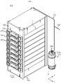
- FIG. 1 is a front perspective view schematically showing a battery pack according to an embodiment of the present disclosure.
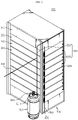
- FIG. 2 is a rear perspective view schematically showing the battery pack according to an embodiment of the present disclosure.
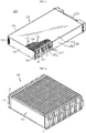
- FIG. 3 is a rear perspective view schematically showing a battery module, employed at the battery pack according to an embodiment of the present disclosure.
- FIG. 4 is a perspective view schematically showing a cell assembly, employed at the battery pack according to an embodiment of the present disclosure.
- FIG. 5 is a conceptual diagram schematically showing components of the battery pack according to an embodiment of the present disclosure.
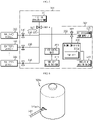
- FIG. 6 is a perspective view schematically showing a second fire extinguishing tank, employed at the battery pack according to an embodiment of the present disclosure.
- FIG. 7 is a perspective view schematically showing a fire plug, employed at a battery pack according to another embodiment of the present disclosure.
- FIG. 8 is a perspective view schematically showing some components of a first fire extinguishing unit, employed at the battery pack according to an embodiment of the present disclosure.
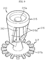
- FIG. 9 is a perspective view schematically showing a distribution valve, employed at the battery pack according to an embodiment of the present disclosure.
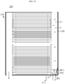
- FIG. 10 is a plan view schematically showing inner components of the battery pack according to an embodiment of the present disclosure.
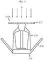
- FIG. 11 is a plan view schematically showing a distribution valve, employed at a battery pack according to another embodiment of the present disclosure.
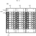
- FIG. 12 is a front view schematically showing an energy storage system according to an embodiment of the present disclosure.
- FIG. 1 is a front perspective view schematically showing a battery pack according to an embodiment of the present disclosure.
- FIG. 2 is a rear perspective view schematically showing the battery pack according to an embodiment of the present disclosure.
- FIG. 3 is a rear perspective view schematically showing a battery module, employed at the battery pack according to an embodiment of the present disclosure.
- FIG. 4 is a perspective view schematically showing a cell assembly, employed at the battery pack according to an embodiment of the present disclosure.
- FIG. 5 is a conceptual diagram schematically showing components of the battery pack according to an embodiment of the present disclosure.
- FIG. 1 is a front perspective view schematically showing a battery pack according to an embodiment of the present disclosure.
- FIG. 2 is a rear perspective view schematically showing the battery pack according to an embodiment of the present disclosure.
- FIG. 3 is a rear perspective view schematically showing a battery module, employed at the battery pack according to an embodiment of the present disclosure.
- FIG. 4 is a perspective view schematically showing a cell assembly, employed at the battery pack according to
- a positive direction of an X-axis arrow refers to a rear direction
- a negative direction thereof refers to a front direction
- a positive direction of a Y-axis arrow refers to a left direction
- a negative direction thereof refers to a right direction
- a positive direction of a Z-axis direction refers to an upper direction
- a negative direction thereof refers to a lower direction.
- a battery pack 400 of the present disclosure includes at least one battery module 200, a first fire extinguishing unit 301, and a second fire extinguishing unit 302.
- the plurality of battery modules 200 may be arranged in one direction.
- the battery module 200 may include at least one cell assembly 100 ( FIG. 4 ).
- the cell assembly 100 may have a plurality of secondary batteries 110 arranged in one direction.
- the secondary battery 110 may be a pouch-type secondary battery 110.
- the cell assembly 100 when viewed in the F direction of FIG. 1 (from the front), the cell assembly 100 may be configured such that a plurality of pouch-type secondary batteries 110 are stacked side by side in the front and rear direction.
- one cell assembly 100 may include 21 pouch-type secondary batteries 110.
- the upper, lower, front, rear, left and right directions will be set based on when viewed in the F direction.
- the pouch-type secondary battery 110 may include an electrode assembly (not shown), an electrolyte solution (not shown), and a pouch 116.
- a positive electrode lead 111 and a negative electrode lead 112 may be formed at left and right ends of the secondary battery 110, which are opposite to each other based on the center of the secondary battery 110. That is, the positive electrode lead 111 may be provided at one end (right end) of the secondary battery 110 based on the center thereof. In addition, the negative electrode lead may be provided at the other end (left end) of the secondary battery 110 based on the center thereof.
- the battery module 200 according to the present disclosure is not limited to the pouch-type secondary battery 110 described above, and various kinds of secondary batteries 110 known at the time of filing of this application may be employed.
- the battery module 200 may include a cooling fan 370 for injecting an external air to the inside.
- the battery module 200 may further include a bus bar assembly 270.
- the bus bar assembly 270 may include at least one bus bar 272 configured to electrically connect the plurality of secondary batteries 110 to each other and at least two bus bar frame 276 configured to mount the at least at least one bus bar 272 at an outer side.
- the at least two bus bar frame 276 may be provided at left and right sides of the cell assembly 100, respectively.
- the module housing 210 may have an inner space to accommodate the cell assembly 100 therein.
- the module housing 210 may include an upper cover 220, a base plate 240, a front cover 260, and a rear cover 250.
- the base plate 240 may have an area larger than the size of a bottom surface of the at least two cell assemblies 100 so as to mount the at least two cell assemblies 100 to an upper portion thereof.
- the base plate 240 may have a plate shape extending in a horizontal direction.
- the upper cover 220 may include an upper wall 224 and a sidewall 226 extending downward from the upper wall 224.
- the upper wall 224 may have a plate shape extending in a horizontal direction to cover an upper portion of the cell assembly 100.
- the sidewall 226 may have a plate shape extending downward from both left and right ends of the upper wall 224 to cover both left and right sides of the cell assembly 100.
- the sidewall 226 may be coupled to a portion of the base plate 240.
- the upper cover 220 may include an upper wall 224 having a plate shape extending in the front, rear, left and right directions.
- the upper cover 220 may include two sidewalls 226 extending downward from both left and right ends of the upper wall 224, respectively.
- lower ends of the two sidewalls 226 may be configured to be coupled with both left and right ends of the base plate 240, respectively.
- the coupling method may be a male and female coupling method or a welding method.
- the front cover 260 may be configured to cover the front side of the plurality of secondary batteries 110.
- the front cover 260 may include a plate larger than the size of the front surface of the plurality of secondary batteries 110. The plate may be erected in a vertical direction.
- the rear cover 250 may be configured to cover the rear side of the cell assembly 100.
- the rear cover 250 may have a plate shape larger than the size of the rear surface of the plurality of secondary batteries 110.
- the module housing 210 may include a gas passage 211 located inside the module housing 210 and configured to discharge the gas generated from the cell assembly 100 to the outside. That is, the module housing 210 may have a gas passage 211 through which the gas generated from the cell assembly 100 flows.
- the gas passage 211 may be a space elongated in the front and rear direction to communicate with the outside.
- the gas passage 211 may be provided at one of the left and right sides or both left and right sides of the cell assembly 100.
- the gas passage 211 may be a space between the upper or lower portion of the cell assembly 100 and the module housing 210. That is, the gas generated from the cell assembly 100 accommodated in the battery module 200 may move to both left and right sides of the cell assembly 100 through the gas passage 211 located at the upper or lower portion of the cell assembly 100 and be discharged out through a plurality of gas discharge holes 212 formed at the end of the gas passage 211 and perforated to communicate with the outside of the battery module 200.
- an inlet hole 264 may be provided at the rear cover 250 located at the rear side of each of the at least two battery modules 200 so that the fire extinguishing agent is introduced therethrough.
- the inlet hole 264 may be positioned to communicate with the gas passage 211. That is, the inlet hole 264 may be configured to communicate with the gas passages 211 located on both left and right sides based on the cell assembly 100.
- An inlet hole 264 may be provided at the rear cover 250 located at the rear side of each of the at least two battery modules 200 so that the fire extinguishing agent is introduced therethrough.
- the inlet hole 264 may be positioned to communicate with the gas passage 211. That is, the inlet hole 264 may be configured to communicate with the gas passages 211 located on both left and right sides based on the cell assembly 100.
- the first fire extinguishing unit 301 may include a first fire detection sensor 311, a first fire extinguishing tank 321, a first pipe 330, and a first valve 343.
- the first fire detection sensor 311 may be configured to detect that a temperature of the at least one battery module 200 rises over a predetermined temperature or smoke is generated at the at least one battery module 200.
- the first fire detection sensor 311 may include a temperature sensor and a smoke sensor (not shown).
- the temperature sensor may be a linear temperature sensor 360.
- the linear temperature sensor 360 may be configured to emit a fire or overheat signal since heat sensing materials coated on two wires are melted when reaching a temperature higher than a reference temperature to cause a short circuit between two wires.
- the heat sensing material may be a thermoplastic resin that melts at 70 °C to 100 °C.
- the thermoplastic resin may be a polyester resin or an acrylic resin.
- the linear temperature sensor 360 may further include an insulating coating material configured to surround the heat sensing material.
- the coating material may include polyvinyl chloride.
- the linear temperature sensor 360 may have a structure extending linearly along at least two battery modules 200 arranged in one direction.
- the battery pack 400 may include eight battery modules 200 arranged in a vertical direction.
- the linear temperature sensor 360 may be configured so that one end thereof is connected to the first controller 351 and extends along the eight battery modules 200 arranged in the vertical direction, and the other end thereof is connected to a resistor 365 at a distal end.
- a bracket (not shown) and a fixing buckle (not shown) may be used to partially fix the position of the linear temperature sensor 360.
- the first fire detection sensor 311 includes the linear temperature sensor 360 along the at least two battery modules 200, it is possible to reduce the manufacturing cost of the battery pack 400.
- the battery pack 400 of the present disclosure uses only one linear temperature sensor 360 to detect the temperature of the plurality of battery modules 200, so a separate signal wire is not required and easy installation is secured due to a light and flexible design. Thus, the manufacturing cost of battery pack 400 may be greatly reduced.
- the linear temperature sensor 360 is useful for setting a plurality of points for more accurate temperature sensing even for one battery module 200. Accordingly, in the present disclosure, it is possible to greatly reduce the failure rate in detecting the occurrence of fire in the battery module 200.
- the smoke sensor may be located at an uppermost portion of the at least two battery modules 200 stacked in the vertical direction. That is, if a fire occurs in the battery module 200, the generated gas may be moved upward, so it is preferable that the smoke sensor is located at the uppermost portion of the at least two battery modules 200.
- the smoke sensor may be configured to transmit a signal to the first controller 351 of the first fire extinguishing unit 301 when detecting smoke.
- the smoke sensor may employ a generally known technology.
- the first fire extinguishing tank 321 may contain a fire extinguishing agent (not shown) therein.
- the fire extinguishing agent may be a concentrated solution of an inorganic salt such as potassium carbonate, a chemical bubble, an air bubble, carbon dioxide, or water.
- the first fire extinguishing tank 321 may have a compressed gas therein to inject or move the fire extinguishing agent at an appropriate pressure along the first pipe 330.
- the capacity of the first fire extinguishing tank 321 may be 59 L
- the compressed gas may be nitrogen of 8 bar
- the fire extinguishing agent may be 40 L of water.
- the fire extinguishing agent is water
- the fire extinguishing agent has a heat shielding effect together with the fire extinguishing and cooling effect, so it is effective in preventing thermal propagation when high-temperature gas and flame are generated due to thermal runaway.
- the first pipe 330 may be configured to be connected to supply the fire extinguishing agent from the first fire extinguishing tank 321 to each of the at least two battery modules 200.
- the first pipe 330 may be made of a material that is not corroded by water.
- the first pipe 330 may be made of stainless steel.
- One end of the first pipe 330 may be connected to an outlet hole 321a of the first fire extinguishing tank 321.
- the other end of the first pipe 330 may have a shape extending to the inside of each of the at least two battery modules 200.
- the first pipe 330 may include a common pipe 333 connected to the outlet hole 321a of the first fire extinguishing tank 320 through which the fire extinguishing agent is discharged, and a distribution pipe 336 having a distributed structure to be connected to each of the at least two battery modules 200 from the common pipe 333.
- the first pipe 330 may include one common pipe 333 connected to the outlet hole 321a of the first fire extinguishing tank 320, and eight distribution pipes 336 branched from the common pipe 333.
- the eight distribution pipes 336 may be configured to be connected to eight battery modules 200.
- the first valve 343 may be configured to supply the fire extinguishing agent from the first fire extinguishing tank 321 into the battery module 200 when an internal gas (air) of the battery module 200 is heated over a predetermined temperature.
- the first valve 343 may include a passive valve (not shown) configured to open an output hole so that the fire extinguishing agent may be injected into the battery module 200 over the predetermined temperature.
- the passive valve may be partially deformed to open the output hole.
- the passive valve may be configured such that its inner configuration is partially deformed by the heat of the heated internal gas to open the output hole.
- the 'predetermined temperature' may be, for example, 100°C or higher.
- the second fire extinguishing unit 302 may include a second fire detection sensor 313, a fire extinguishing agent supply unit 325, and a second valve 348.
- the second fire detection sensor 313 may be configured to detect that the temperature of the at least one battery module 200 rises over the predetermined temperature or smoke is generated at the at least one battery module 200.
- the second fire detection sensor 313 may include a temperature sensor and a smoke sensor.
- the temperature sensor may be a linear temperature sensor 360.
- the linear temperature sensor 360 may have the same configuration as the linear temperature sensor 360 of the first fire extinguishing unit 301.
- the linear temperature sensor 360 may be configured to contact the battery module 200.
- the linear temperature sensor 360 since the linear temperature sensor 360 has the same configuration as the linear temperature sensor of the first fire extinguishing unit 301, it will not be described in detail.
- the smoke sensor may be configured to detect smoke emitted from the at least two battery modules 200.
- the smoke sensor may have the same configuration as the smoke sensor of the first fire extinguishing unit 301.
- the fire extinguishing agent supply unit 325 may be configured to supply the fire extinguishing agent to the first pipe 330 through the second pipe 338.
- the fire extinguishing agent supply unit 325 may be connected to the other end of the second pipe 338.
- FIG. 6 is a perspective view schematically showing a second fire extinguishing tank, employed at the battery pack according to an embodiment of the present disclosure.
- the second pipe 338 may be configured to have one end connected to the first pipe 330.
- the second pipe 338 may be made of a material that is not corroded by water.
- the second pipe 338 may be made of stainless steel.
- the second pipe 338 may be configured to have one end connected to an outlet 325al of a second fire extinguishing tank 325a.
- the second pipe 338 may have the other end connected to the first pipe 330 extending to the inside of each of the at least two battery modules 200.
- the battery pack 400 of the present disclosure further includes the second fire extinguishing unit 302 separately from the first fire extinguishing unit 301, even though the fire of the battery module 200 is not extinguished through the first fire extinguishing unit 301 due to a failure or malfunction of the first fire extinguishing unit 301, the fire may be extinguished additionally using the separate second fire extinguishing unit 302. Accordingly, the battery module 200 of the present disclosure may maximize safety through double fire extinguishing.
- the fire extinguishing agent supply unit 325 may include the second fire extinguishing tank 325a.
- the second fire extinguishing tank 325a may contain a fire extinguishing agent (not shown) therein.
- the fire extinguishing agent may be a concentrated solution of an inorganic salt such as potassium carbonate, a chemical bubble, an air bubble, carbon dioxide, or water.
- the second fire extinguishing tank 325a may spray the fire extinguishing agent at an appropriate pressure.
- the capacity of the second fire extinguishing tank 325a may be 1000 liters.
- the second fire extinguishing tank 325a may be placed higher than the battery module 200. That is, the second fire extinguishing tank 325a may send the fire extinguishing agent contained therein to the battery module 200 using potential energy.
- the fire extinguishing agent may be water.
- water if water is used as the fire extinguishing agent, when the water is sprayed inside the battery module 200, the water has a heat shielding effect together with the fire extinguishing and cooling effect, so it is effective in preventing thermal propagation when high-temperature gas and flame are generated due to thermal runaway. As a result, it is possible to effectively prevent a fire or thermal runaway from propagating among the plurality of battery modules 200.
- the fire extinguishing agent supply unit 325 includes the second fire extinguishing tank 325a containing the fire extinguishing agent therein, the second fire extinguishing tank 325a may supply the fire extinguishing agent in a higher capacity to the battery module 200, thereby preventing that the fire is not extinguished due to a lack of the fire extinguishing agent.
- FIG. 7 is a perspective view schematically showing a fire plug, employed at a battery pack according to another embodiment of the present disclosure.
- the fire extinguishing agent supply unit 325 may include a fire plug 325b configured to supply tap water from the outside.
- An output hole of the fire plug 325b may be configured to be connected to the other end of the second pipe 338.
- the fire extinguishing agent supply unit 325 since the fire extinguishing agent supply unit 325 according to another embodiment of the present disclosure has the fire plug 325b instead of the fire extinguishing tank, it is economical due to low maintenance cost, compared to the second fire extinguishing tank.
- the first fire extinguishing unit 301 may include a first control unit 351.
- the first control unit 351 may be configured to control the first valve 343 to be opened or closed according to a signal received from the first fire detection sensor 311.
- the first control unit 351 may be configured to open the first valve 343 when a temperature higher than a predetermined temperature is detected by the first fire detection sensor 311.
- the first control unit 351 may be configured to transmit a signal that controls the first valve 343.
- the first fire detection sensor 311 may be connected to the first control unit 351 by using a wire capable of transmitting and receiving an electrical signal to/from the first control unit 351.
- the second fire extinguishing unit 302 may include a second control unit 355.
- the second control unit 355 may be configured to control the second valve 348 to be opened or closed according to a signal received from the second fire detection sensor 313.
- the second control unit 355 may be configured to open the second valve 348 when a temperature higher than a predetermined temperature is detected by the second fire detection sensor 313.
- the second control unit 355 may be configured to transmit a signal that controls the second valve 348.
- the second fire detection sensor 313 may be connected to the second control unit 355 by using a wire capable of transmitting and receiving an electrical signal to/from the second control unit 355.
- the first control unit 351 may be configured to transmit a fire signal to the second control unit 355, when receiving the fire signal from the first fire detection sensor 311 since the first fire detection sensor 311 detects that the temperature of the battery module 200 is over a predetermined temperature or detects smoke.
- the second control unit 355 may be configured to open the second valve 348 if the second fire detection sensor 313 detects that the battery module 200 is kept over the predetermined temperature even though a predetermined time passes elapses after receiving the fire signal from the first control unit 351.
- the predetermined time may be 10 minutes.
- the predetermined temperature may be 200°C or higher.
- the second control unit 355 may include a switch 355a configured to allow a user to manually open the second valve 348 directly. That is, if the switch 355a is turned on, the second control unit 355 may open the second valve 348 to supply the fire extinguishing agent to the battery module 200 where fire occurs.
- the first fire extinguishing unit 301 further includes a first control unit 351 configured to control the first valve 343 to be opened or closed according to a signal received from the first fire detection sensor 311 and the second fire extinguishing unit 302 further includes a second control unit 355 configured to control the second valve 348 to be opened or closed according to a signal received from the second fire detection sensor 313, when a fire or thermal runaway occurs at the battery module 200, even though the first valve 343 cannot be opened or closed due to a malfunction or failure of the first control unit 351, the second control unit 355 may open the second valve 348, thereby securing reliable fire extinguishing.
- the first pipe 330 may include a common pipe 333 and a distribution pipe 336.
- the common pipe 333 may be connected to the outlet hole 321a of the first fire extinguishing tank 321 through which the fire extinguishing agent is discharged.
- the distribution pipe 336 may have a distributed structure so as to be connected to each of the at least two battery modules 200 from the common pipe 333.
- the first pipe 330 may include one common pipe 333 connected to the outlet hole 321a of the first fire extinguishing tank 321, and eight distribution pipes 336 branched from the common pipe 333.
- the eight distribution pipes 336 may be configured to be connected to eight battery modules 200.
- the first valve 343 may be located at any portion of the common pipe 333 to open and close the common pipe 333.
- the first valve 343 may be configured to connect the common pipe 333 and the first fire extinguishing tank 321 to each other. That is, the first valve 343 may be installed at a start end of the common pipe 333.
- the first valve 343 may be an active valve that is controlled to be opened or closed by the first control unit 351. More specifically, the active valve may be, for example, a control valve, an electric valve, a solenoid valve, or a pneumatic valve.
- the active valve 343 may be configured to supply the fire extinguishing agent from the first fire extinguishing tank 321 to the battery module 200 whose internal temperature has risen over the predetermined temperature.
- the active valve 343 may be configured to be actively opened by the first control unit 351 when the first control unit 351 senses that the internal temperature of the battery module 200 rises over the predetermined temperature.
- the first control unit 351 may be located on the battery module 200 provided at an uppermost side among the plurality of battery modules 200.
- the battery pack 400 of the present disclosure since the battery pack 400 of the present disclosure includes the first valve 343 provided as an active valve that is controlled to be opened or closed by the first control unit 351, when a fire or thermal runaway occurs at the battery pack 400, it is possible to construct an unmanned system capable of carrying out fire extinguishing. Accordingly, it is possible to secure faster fire extinguishing capacity and reduced maintenance cost.
- FIG. 8 is a perspective view schematically showing some components of a first fire extinguishing unit, employed at the battery pack according to an embodiment of the present disclosure.
- FIG. 8 depicts the common pipe 333, the distribution pipe 336, and the distribution valve 310 provided at an end of the distribution pipe 336.
- the first fire extinguishing unit 301 may further include a distribution valve 310 located at any portion of the distribution pipe 336 to open and close the distribution pipe 336.
- the distribution valve 310 may include a glass bulb 312 serving as an internal component thereof, which is located at a portion of the gas passage 211 inside the module housing 210.
- the distribution valve 310 may be disposed to protrude toward the battery module 200. At least a portion of the distribution valve 310 may be inserted into the module housing 210 from the rear of the battery module 200.
- the glass bulb 312 and the dispersion unit 317 of the distribution valve 310 may be inserted through the inlet hole 264 so as to be positioned at the rear end of the gas passage 211.
- the distribution valve 310 may be a passive valve.
- the passive valve may be configured to deform some configuration thereof to open the output hole.
- the passive valve may be configured to open the output hole by partially deforming the internal structure thereof by the heat of the internal gas whose temperature has risen.
- the 'predetermined temperature' may be, for example, 100°C or higher.
- the distribution valve 310 may be inserted into the module housing 210. At this time, the fire extinguishing agent provided at the rear end of the gas passage 211 moves to the front of the gas passage 211, and a part of the fire extinguishing agent moves to pass through the cell assembly 100.
- the distribution valve 310 of the present disclosure is provided as a passive valve configured to open the output hole by deforming some internal configuration thereof when the temperature of the battery module 200 rises over the predetermined temperature, it is possible to respond to a temperature change without separately controlling the valve of the first control unit 351, thereby securing rapid extinguishing ability against thermal runaway or fire of the battery module 200. That is, even if the battery management system malfunctions, thermal runaway or fire may be stably extinguished achieved by the fire extinguishing valve without controlling the BMS, thereby effectively increasing the safety of the battery pack 400.
- FIG. 9 is a perspective view schematically showing a distribution valve, employed at the battery pack according to an embodiment of the present disclosure.
- the distribution valve 310 may include a glass bulb 312 configured to seal the output hole 315a at ordinary time, but configured to open the output hole 315a by being partially broken when being exposed to the internal gas of the battery module 200 over the predetermined temperature.
- the glass bulb 312 may have a predetermined liquid (not shown) contained therein.
- the liquid may have a property that the volume increases as the temperature rises.
- the glass bulb 312 may be configured to seal a passage (output hole) through which the fluid of the fire extinguishing valve 310 flows.
- the glass bulb 312 may be configured to be broken due to volume expansion of the predetermined liquid at a predetermined temperature, for example, 70°C to 100°C or above.
- the liquid may be water. That is, if the distribution valve 310 is located inside the battery module 200, when the internal temperature of the battery module 200 rises over the predetermined temperature, the glass bulb 312 closing the passage through which the fire extinguishing agent of the distribution valve 310 flows may be at least partially broken to open the output hole 315a of the distribution valve 310.
- the distribution valve 310 may further include a dispersion unit 317 configured to disperse the fire extinguishing agent discharged from the output hole 315a in all directions. The dispersion unit 317 may be configured to disperse the fire extinguishing agent discharged from the output hole 315a.
- the distribution valve 310 may include a top portion 315 and a connection portion 316.
- the top portion 315 may have a tubular shape configured such that the output hole 315a of the valve is formed therein and the output hole 315a is sealed by one end of the glass bulb 312.
- the tubular shape may have a pipe diameter continuously decreasing toward the glass bulb 312.
- connection portion 316 may extend from the top portion 315 to the side of the glass bulb 312 to cover the glass bulb 312, and two arms 316a of the connection portion 316 may extend in one direction from the top portion 315 and be gathered to the center again to fix the other end of the glass bulb 312. At this time, the other end of the glass bulb 312 may be located in a portion where the two arms of the connection portion 316 are gathered.
- the dispersion unit 317 may include a distributing protrusion 317a.
- the distributing protrusion 317a may have a shape that is divided into a plurality of parts from the end of the body of the dispersion unit 317 to extend horizontally at regular intervals so that the fire extinguishing agent discharged from the output hole 315a is dispersed.
- the distribution valve 310 of the present disclosure since the distribution valve 310 of the present disclosure includes a glass bulb 312 configured to seal the output hole 315a, but configured to open the output hole 315a as being partially broken when being exposed to the internal gas of the battery module 200 over the predetermined temperature, and a dispersion unit 317 configured to disperse the fire extinguishing agent discharged from the output hole 315a, it is possible to open the distribution valve 310 at a response speed by the high internal temperature of the battery module 200 at which thermal runaway or fire occurs. Moreover, since the dispersion unit 317 evenly sprays the supplied fire extinguishing agent, the extinguishing ability may be effectively increased.
- FIG. 10 is a plan view schematically showing inner components of the battery pack according to an embodiment of the present disclosure.
- the distribution valve 310 may be configured such that the glass bulb 312 is positioned at a portion of the gas passage 211 formed between the cell assembly 100 and the sidewall 226 of the module housing 210.
- the distribution valve 310 may be inserted into the inlet hole 264 and located in a part of the gas passage 211 so that the glass bulb 312 is exposed to the gas generated from the cell assembly 100.
- the glass bulb 312 of the distribution valve 310 may be inserted into the inlet hole 264 so as to be exposed to the gas generated from the cell assembly 100.
- the distribution valve 310 since at least a part of the distribution valve 310 is located in a part of the gas passage 211 so that the glass bulb 312 is exposed to the gas generated from the cell assembly 100, when a thermal runaway or fire occurs at the cell assembly 100, it is possible to effectively receive heat transfer from the high-temperature air or gas moving along the gas passage 211, so that the glass bulb 312 of the distribution valve 310 bursts quickly to take a fire extinguishing action fast.
- the module housing 210 may further include a guide block 382 therein.
- the guide block 382 may have an inclined surface 382a that guides the gas G generated from the cell assembly 100 to flow while facing the exposed portion of the glass bulb 312.
- the guide block 382 may have a triangular shape on a plane.
- the high-temperature gas G flowing from the front to the rear of the gas passage 211 may flow along the inclined surface 382a of the guide block 382, so that the flow of the gas G is guided toward the glass bulb 312 of the distribution valve 310.
- the battery module 200 since the battery module 200 includes the guide block 382 having the inclined surface 382a that guides the gas G generated from the cell assembly 100 to flow while facing the exposed portion of the glass bulb 312, it is possible to effectively reduce that the contact of the glass bulb 312 of the distribution valve 310 with the high-temperature gas G is disturbed. Accordingly, the distribution valve 310 may operate with high reliability, and the operating time may be effectively reduced.
- FIG. 11 is a plan view schematically showing a distribution valve, employed at the battery pack according to another embodiment of the present disclosure.
- a distribution valve 310A may further include a gas guide 318, when compared with the distribution valve 310 shown in FIG. 9 .
- the distribution valve 310A shown in FIG. 11 is the same as the distribution valve 310 shown in FIG. 9 , except for the gas guide 318. Therefore, the top portion 315, the connection portion 316 and the dispersion unit 317, already described above will not be described again in detail.
- the gas guide 318 may be configured such that a larger amount of high-temperature gas G comes into contact with the glass bulb 312.
- the gas guide 318 may be shaped to extend from the top portion 315 toward the dispersion unit 317.
- the gas guide 318 may have a structure that is widened in at least two of left, right, upper and lower directions. For example, as shown in FIG. 11 , the gas guide 318 may extend from the left and right sides of the top portion 315 toward the dispersing protrusion 317a.
- the gas guide 318 may have a structure that is widened from the top portion 315 in the left, right, upper and lower directions.
- the dispersion unit 314A of the distribution valve 310A since the dispersion unit 314A of the distribution valve 310A according to the present disclosure includes the gas guide 318 extending from the top portion 315 toward the dispersion unit 317 and having a structure that is widened in at least two of left, right, upper and lower directions, the high-temperature gas G flowing to both sides of the glass bulb 312 may be guided to flow toward the glass bulb 312 without passing directly. Accordingly, the distribution valve 310A may operate with high reliability, and the operating time of the distribution valve 310A may be effectively reduced.
- FIG. 12 is a front view schematically showing an energy storage system according to an embodiment of the present disclosure.
- a battery rack 500 may include at least one battery module 200 and a battery pack 400 having a pack BMS 350.
- the pack BMS 350 may be located above the battery module 200 that is located at a top end T among the plurality of battery modules 200.
- the battery rack 500 may further include other components such as a battery management system (BMS) inside or outside the rack case 510.
- BMS battery management system
- the rack case 510 may also be configured to accommodate the plurality of battery modules 200 of the battery pack 400 to be vertically stacked. Inside the rack case 510, the battery module 200 may be mounted such that its lower surface is in a parallel shape to the horizontal surface.
- the horizontal direction may refer to a direction parallel to the ground when the battery module 200 is placed on the ground, and may also refer to at least one direction on a plane perpendicular to the vertical direction.
- the rack case 510 is configured to have at least one side openable, and the battery module 200 may be inserted into the inner space through the open side.
- the rack case 510 may also be configured to allow such an open side to be closed.
- an energy storage system 600 may include two or more battery racks 500.
- the two or more battery racks 500 may be arranged in one direction.
- the energy storage system 600 may be configured such that three battery racks 500 are arranged in one direction.
- the energy storage system 600 may have a separate central controller (not shown) capable of controlling charging and discharging of three battery racks 500.
- Reference Signs 200 battery module 100: cell assembly 110: secondary battery 210: module housing 211: gas passage 212: gas discharge hole 264: inlet hole 301, 302: first fire extinguishing unit, second fire extinguishing unit 311, 313: first fire detection sensor, second fire detection sensor 343, 348, 310: first valve, second valve, distribution valve 321: first fire extinguishing tank 321a: outlet hole 325, 325a, 325b: fire extinguishing agent supply unit, second fire extinguishing tank, fire plug 330, 333, 336: first pipe, common pipe, distribution pipe 338: second pipe 312: glass bulb 317: dispersion unit 315, 316, 317: top portion, connection portion, dispersion unit 382: guide block 318: gas guide 351, 355: first control unit, second control unit 400: battery pack 500: battery rack 510: rack case 600: energy storage system
Landscapes
- Health & Medical Sciences (AREA)
- Public Health (AREA)
- Business, Economics & Management (AREA)
- Emergency Management (AREA)
- Chemical & Material Sciences (AREA)
- Chemical Kinetics & Catalysis (AREA)
- Electrochemistry (AREA)
- General Chemical & Material Sciences (AREA)
- Engineering & Computer Science (AREA)
- Manufacturing & Machinery (AREA)
- Battery Mounting, Suspending (AREA)
- Gas Exhaust Devices For Batteries (AREA)
Abstract
Description
- The present disclosure relates to a battery pack including a fire extinguishing unit, and a battery pack and an energy storage system including the battery pack, and more particularly, to a battery pack having a reduced risk of secondary ignition or explosion.
- The present application claims priority to
Korean Patent Application No. 10-2020-0011324 filed on January 30, 2020 - Secondary batteries commercialized at the present include nickel cadmium batteries, nickel hydrogen batteries, nickel zinc batteries, and lithium secondary batteries. Among them, lithium secondary batteries are in the spotlight due to free advantages such as free charging and discharging by little memory effect compared to nickel-based secondary batteries, and very low self-discharge rate and high energy density.
- The lithium secondary battery mainly uses a lithium-based oxide and a carbon material as a positive electrode active material and a negative electrode active material, respectively. The lithium secondary battery includes an electrode assembly in which a positive electrode plate and a negative electrode plate respectively coated with the positive electrode active material and the negative electrode active material are disposed with a separator being interposed therebetween, and an exterior, namely a battery pouch exterior, for hermetically storing the electrode assembly together with an electrolyte.
- Recently, secondary batteries are widely used not only in small devices such as portable electronic devices, but also in middle-sized or large-sized devices such as vehicles and energy storage systems. When used in the middle-sized or large-sized device, a large number of secondary batteries are electrically connected to increase capacity and output. In particular, pouch-type secondary batteries are widely used in the middle-sized or large-sized devices since they may be easily stacked.
- Meanwhile, recently, as the need for a large-capacity structure increases along with the use as an energy storage source, the demand for a battery pack including a plurality of secondary batteries electrically connected in series and/or in parallel, and a battery module accommodating the secondary batteries therein, and a battery management system (BMS) is increasing.
- In addition, the battery pack generally includes an outer housing made of a metal material to protect or store the plurality of secondary batteries from an external shock. Meanwhile, the demand for high-capacity battery packs is increasing recently.
- However, since the conventional battery pack or the conventional battery rack has a plurality of battery modules, if the secondary batteries of each battery module generates thermal runaway to cause ignition or explosion, heat or flame may be transferred to neighboring secondary batteries to cause secondary explosions, so efforts to prevent secondary ignition or explosion are increasing.
- Accordingly, it is necessary to develop a fast and complete fire extinguishing technology to take immediate action when thermal runaway occurs in some secondary batteries in the battery pack or the battery rack. In addition, there is a need for an alternative method for extinguishing fire in case the battery management system for controlling whether or not to perform fire extinguishing for fire suppression is inoperative or malfunctions when fire occurs at battery modules.
- The present disclosure is designed to solve the problems of the related art, and therefore the present disclosure is directed to providing a battery pack, which reduces the risk of secondary ignition or explosion.
- These and other objects and advantages of the present disclosure may be understood from the following detailed description and will become more fully apparent from the exemplary embodiments of the present disclosure. Also, it will be easily understood that the objects and advantages of the present disclosure may be realized by the means shown in the appended claims and combinations thereof.
- In one aspect of the present disclosure, there is provided a battery pack, comprising:
- at least one battery module;
- a first fire extinguishing unit including a first fire detection sensor configured to detect that a temperature of the at least one battery module rises over a predetermined temperature or smoke is generated at the at least one battery module, a first fire extinguishing tank configured to accommodate a fire extinguishing agent therein, a first pipe configured to connect the first fire extinguishing tank and the at least one battery module so that the fire extinguishing agent is supplied from the first fire extinguishing tank to the at least one battery module, and a first valve provided to the first pipe and configured to be opened to supply the fire extinguishing agent from the first fire extinguishing tank to the at least one battery module when the temperature of the at least one battery module rises over the predetermined temperature or smoke is generated at the at least one battery module; and
- a second fire extinguishing unit including a second fire detection sensor configured to detect that the temperature of the at least one battery module rises over the predetermined temperature or smoke is generated at the at least one battery module, a second pipe having one end connected to the first pipe, a fire extinguishing agent supply unit connected to the other end of the second pipe so that the fire extinguishing agent is supplied to the first pipe through the second pipe, and a second valve configured to be opened to supply the fire extinguishing agent from the fire extinguishing agent supply unit to the first pipe through the second pipe when the temperature of the at least one battery module rises over the predetermined temperature or smoke is generated at the at least one battery module.
- Also, the fire extinguishing agent supply unit may include a second fire extinguishing tank configured to accommodate a fire extinguishing agent therein, or a fire plug connected to the second pipe and configured to supply water from the outside, or both of the second fire extinguishing tank and the fire plug.
- Moreover, the first fire extinguishing unit may further include a first control unit configured to control the first valve to be opened or closed according to a signal received from the first fire detection sensor,
- the second fire extinguishing unit may further include a second control unit configured to control the second valve to be opened or closed according to a signal received from the second fire detection sensor,
- the first control unit may transmit a fire signal to the second control unit, when receiving the fire signal from the first fire detection sensor, and
- the second control unit may be configured to open the second valve, when the second fire detection sensor detects that the battery module is kept over the predetermined temperature even through a predetermined time passes after receiving the fire signal from the first control unit.
- In addition, the first pipe may include:
- a common pipe connected to an outlet hole of the first fire extinguishing tank through which the fire extinguishing agent is discharged; and
- in case at least two battery modules are provided, a distribution pipe having a distributed structure connected to each of the at least two battery modules from the common pipe,
- the first valve may be located at a portion of the common pipe to open or close the common pipe, and
- the first valve may be an active valve controlled to be opened or closed by the first control unit.
- Further, the first fire extinguishing unit may further include a distribution valve located at a portion of the distribution pipe to open or close the distribution pipe, and
the distribution valve may be a passive valve configured to open an output hole thereof by deforming an inner configuration thereof partially when the temperature of the battery module rises over the predetermined temperature. - Also, the distribution valve may include:
- a glass bulb configured to close the output hole and configured to open the output hole by being at least partially broken when the battery module is exposed to an internal gas over the predetermined temperature; and
- a dispersion unit configured to disperse the fire extinguishing agent discharged from the output hole.
- In addition, the battery module may include at least one cell assembly having a plurality of secondary batteries, and a module housing having an inner space capable of accommodating the at least one cell assembly,
- the module housing may have a gas passage configured therein to discharge gas generated from the cell assembly to the outside, and
- the glass bulb of the distribution valve may be located at a portion of the gas passage.
- Further, the distribution valve may further include a gas guide configured to guide gas generated from the cell assembly to come into contact with the glass bulb.
- Also, in another aspect of the present disclosure, there is also provided a battery rack, comprising: a battery pack; and a rack case configured to accommodate the battery pack.
- Moreover, in another aspect of the present disclosure, there is also provided an energy storage system, comprising two or more battery racks.
- According to an embodiment of the present disclosure, since the battery pack of the present disclosure further includes the second fire extinguishing unit separately from the first fire extinguishing unit, even though the fire of the battery module is not extinguished through the first fire extinguishing unit due to a failure or malfunction of the first fire extinguishing unit, the fire may be extinguished additionally using the separate second fire extinguishing unit. Accordingly, the battery module of the present disclosure may maximize safety through double fire extinguishing.
- Also, according to an embodiment of the present disclosure, since the first fire extinguishing unit further includes a first control unit configured to control the first valve to be opened or closed according to a signal received from the first fire detection sensor and the second fire extinguishing unit further includes a second control unit configured to control the second valve to be opened or closed according to a signal received from the second fire detection sensor, when a fire or thermal runaway occurs at the battery module, even though the first valve cannot be opened or closed due to a malfunction or failure of the first control unit, the second control unit may open the second valve, thereby securing reliable fire extinguishing.
- Moreover, according to an embodiment of the present disclosure, since the distribution valve of the present disclosure includes a glass bulb configured to seal the output hole, but configured to open the output hole as being partially broken when being exposed to the internal gas of the battery module over the predetermined temperature, and a dispersion unit configured to disperse the fire extinguishing agent discharged from the output hole, it is possible to open the distribution valve at a response speed by the high internal temperature of the battery module at which thermal runaway or fire occurs. Moreover, since the dispersion unit evenly sprays the supplied fire extinguishing agent, the extinguishing ability may be effectively increased.
- Further, according to an embodiment of the present disclosure, since the dispersion unit of the distribution valve according to the present disclosure includes the gas guide extending from the top portion toward the dispersion unit and having a structure that is widened in at least two of left, right, upper and lower directions, the high-temperature gas flowing to both sides of the glass bulb may be guided to flow toward the glass bulb without passing directly. Accordingly, the distribution valve may operate with high reliability, and the operating time of the distribution valve may be effectively reduced.
- The accompanying drawings illustrate a preferred embodiment of the present disclosure and together with the foregoing disclosure, serve to provide further understanding of the technical features of the present disclosure, and thus, the present disclosure is not construed as being limited to the drawing.
-
FIG. 1 is a front perspective view schematically showing a battery pack according to an embodiment of the present disclosure. -
FIG. 2 is a rear perspective view schematically showing the battery pack according to an embodiment of the present disclosure. -
FIG. 3 is a rear perspective view schematically showing a battery module, employed at the battery pack according to an embodiment of the present disclosure. -
FIG. 4 is a perspective view schematically showing a cell assembly, employed at the battery pack according to an embodiment of the present disclosure. -
FIG. 5 is a conceptual diagram schematically showing components of the battery pack according to an embodiment of the present disclosure. -
FIG. 6 is a perspective view schematically showing a second fire extinguishing tank, employed at the battery pack according to an embodiment of the present disclosure. -
FIG. 7 is a perspective view schematically showing a fire plug, employed at a battery pack according to another embodiment of the present disclosure. -
FIG. 8 is a perspective view schematically showing some components of a first fire extinguishing unit, employed at the battery pack according to an embodiment of the present disclosure. -
FIG. 9 is a perspective view schematically showing a distribution valve, employed at the battery pack according to an embodiment of the present disclosure. -
FIG. 10 is a plan view schematically showing inner components of the battery pack according to an embodiment of the present disclosure. -
FIG. 11 is a plan view schematically showing a distribution valve, employed at a battery pack according to another embodiment of the present disclosure. -
FIG. 12 is a front view schematically showing an energy storage system according to an embodiment of the present disclosure. - Hereinafter, preferred embodiments of the present disclosure will be described in detail with reference to the accompanying drawings. Prior to the description, it should be understood that the terms used in the specification and the appended claims should not be construed as limited to general and dictionary meanings, but interpreted based on the meanings and concepts corresponding to technical aspects of the present disclosure on the basis of the principle that the inventor is allowed to define terms appropriately for the best explanation.
- Therefore, the description proposed herein is just a preferable example for the purpose of illustrations only, not intended to limit the scope of the disclosure, so it should be understood that other equivalents and modifications could be made thereto without departing from the scope of the disclosure.
-
FIG. 1 is a front perspective view schematically showing a battery pack according to an embodiment of the present disclosure.FIG. 2 is a rear perspective view schematically showing the battery pack according to an embodiment of the present disclosure.FIG. 3 is a rear perspective view schematically showing a battery module, employed at the battery pack according to an embodiment of the present disclosure.FIG. 4 is a perspective view schematically showing a cell assembly, employed at the battery pack according to an embodiment of the present disclosure. Also,FIG. 5 is a conceptual diagram schematically showing components of the battery pack according to an embodiment of the present disclosure. In addition, inFIG. 1 , a positive direction of an X-axis arrow refers to a rear direction, a negative direction thereof refers to a front direction, a positive direction of a Y-axis arrow refers to a left direction, a negative direction thereof refers to a right direction, and a positive direction of a Z-axis direction refers to an upper direction, and a negative direction thereof refers to a lower direction. - Referring to
FIGS. 1 to 5 , abattery pack 400 of the present disclosure includes at least onebattery module 200, a firstfire extinguishing unit 301, and a secondfire extinguishing unit 302. - First, if a plurality of
battery modules 200 are provided, the plurality ofbattery modules 200 may be arranged in one direction. In this case, thebattery module 200 may include at least one cell assembly 100 (FIG. 4 ). Thecell assembly 100 may have a plurality ofsecondary batteries 110 arranged in one direction. - Also, the
secondary battery 110 may be a pouch-typesecondary battery 110. For example, as shown inFIG. 4 , when viewed in the F direction ofFIG. 1 (from the front), thecell assembly 100 may be configured such that a plurality of pouch-typesecondary batteries 110 are stacked side by side in the front and rear direction. For example, as shown inFIG. 4 , onecell assembly 100 may include 21 pouch-typesecondary batteries 110. - Meanwhile, in this specification, unless otherwise specified, the upper, lower, front, rear, left and right directions will be set based on when viewed in the F direction.
- In particular, the pouch-type
secondary battery 110 may include an electrode assembly (not shown), an electrolyte solution (not shown), and apouch 116. - Moreover, a
positive electrode lead 111 and anegative electrode lead 112 may be formed at left and right ends of thesecondary battery 110, which are opposite to each other based on the center of thesecondary battery 110. That is, thepositive electrode lead 111 may be provided at one end (right end) of thesecondary battery 110 based on the center thereof. In addition, the negative electrode lead may be provided at the other end (left end) of thesecondary battery 110 based on the center thereof. - However, the
battery module 200 according to the present disclosure is not limited to the pouch-typesecondary battery 110 described above, and various kinds ofsecondary batteries 110 known at the time of filing of this application may be employed. - In addition, the
battery module 200 may include a coolingfan 370 for injecting an external air to the inside. - Meanwhile, referring to
FIG. 4 again, thebattery module 200 may further include abus bar assembly 270. Specifically, thebus bar assembly 270 may include at least onebus bar 272 configured to electrically connect the plurality ofsecondary batteries 110 to each other and at least twobus bar frame 276 configured to mount the at least at least onebus bar 272 at an outer side. The at least twobus bar frame 276 may be provided at left and right sides of thecell assembly 100, respectively. - Meanwhile, the
module housing 210 may have an inner space to accommodate thecell assembly 100 therein. Specifically, when viewed directly in the F direction ofFIG. 1 , themodule housing 210 may include anupper cover 220, abase plate 240, afront cover 260, and arear cover 250. - Specifically, the
base plate 240 may have an area larger than the size of a bottom surface of the at least twocell assemblies 100 so as to mount the at least twocell assemblies 100 to an upper portion thereof. Thebase plate 240 may have a plate shape extending in a horizontal direction. - In addition, the
upper cover 220 may include anupper wall 224 and asidewall 226 extending downward from theupper wall 224. Theupper wall 224 may have a plate shape extending in a horizontal direction to cover an upper portion of thecell assembly 100. Thesidewall 226 may have a plate shape extending downward from both left and right ends of theupper wall 224 to cover both left and right sides of thecell assembly 100. - In addition, the
sidewall 226 may be coupled to a portion of thebase plate 240. For example, as shown inFIG. 3 , theupper cover 220 may include anupper wall 224 having a plate shape extending in the front, rear, left and right directions. Theupper cover 220 may include twosidewalls 226 extending downward from both left and right ends of theupper wall 224, respectively. Further, lower ends of the twosidewalls 226 may be configured to be coupled with both left and right ends of thebase plate 240, respectively. In this case, the coupling method may be a male and female coupling method or a welding method. - Moreover, the
front cover 260 may be configured to cover the front side of the plurality ofsecondary batteries 110. For example, thefront cover 260 may include a plate larger than the size of the front surface of the plurality ofsecondary batteries 110. The plate may be erected in a vertical direction. - In addition, the
rear cover 250 may be configured to cover the rear side of thecell assembly 100. For example, therear cover 250 may have a plate shape larger than the size of the rear surface of the plurality ofsecondary batteries 110. - In addition, the
module housing 210 may include agas passage 211 located inside themodule housing 210 and configured to discharge the gas generated from thecell assembly 100 to the outside. That is, themodule housing 210 may have agas passage 211 through which the gas generated from thecell assembly 100 flows. Here, thegas passage 211 may be a space elongated in the front and rear direction to communicate with the outside. Thegas passage 211 may be provided at one of the left and right sides or both left and right sides of thecell assembly 100. - Moreover, the
gas passage 211 may be a space between the upper or lower portion of thecell assembly 100 and themodule housing 210. That is, the gas generated from thecell assembly 100 accommodated in thebattery module 200 may move to both left and right sides of thecell assembly 100 through thegas passage 211 located at the upper or lower portion of thecell assembly 100 and be discharged out through a plurality of gas discharge holes 212 formed at the end of thegas passage 211 and perforated to communicate with the outside of thebattery module 200. - In addition, an
inlet hole 264 may be provided at therear cover 250 located at the rear side of each of the at least twobattery modules 200 so that the fire extinguishing agent is introduced therethrough. Theinlet hole 264 may be positioned to communicate with thegas passage 211. That is, theinlet hole 264 may be configured to communicate with thegas passages 211 located on both left and right sides based on thecell assembly 100. Aninlet hole 264 may be provided at therear cover 250 located at the rear side of each of the at least twobattery modules 200 so that the fire extinguishing agent is introduced therethrough. Theinlet hole 264 may be positioned to communicate with thegas passage 211. That is, theinlet hole 264 may be configured to communicate with thegas passages 211 located on both left and right sides based on thecell assembly 100. - Referring to
FIG. 5 again to along withFIGS. 1 to 3 , the firstfire extinguishing unit 301 may include a firstfire detection sensor 311, a firstfire extinguishing tank 321, afirst pipe 330, and afirst valve 343. - In addition, the first
fire detection sensor 311 may be configured to detect that a temperature of the at least onebattery module 200 rises over a predetermined temperature or smoke is generated at the at least onebattery module 200. - Specifically, the first
fire detection sensor 311 may include a temperature sensor and a smoke sensor (not shown). The temperature sensor may be alinear temperature sensor 360. - For example, the
linear temperature sensor 360 may be configured to emit a fire or overheat signal since heat sensing materials coated on two wires are melted when reaching a temperature higher than a reference temperature to cause a short circuit between two wires. For example, the heat sensing material may be a thermoplastic resin that melts at 70 °C to 100 °C. For example, the thermoplastic resin may be a polyester resin or an acrylic resin. Additionally, thelinear temperature sensor 360 may further include an insulating coating material configured to surround the heat sensing material. The coating material may include polyvinyl chloride. - In addition, the
linear temperature sensor 360 may have a structure extending linearly along at least twobattery modules 200 arranged in one direction. For example, as shown inFIG. 2 , thebattery pack 400 may include eightbattery modules 200 arranged in a vertical direction. Thelinear temperature sensor 360 may be configured so that one end thereof is connected to thefirst controller 351 and extends along the eightbattery modules 200 arranged in the vertical direction, and the other end thereof is connected to aresistor 365 at a distal end. At this time, a bracket (not shown) and a fixing buckle (not shown) may be used to partially fix the position of thelinear temperature sensor 360. - Therefore, according to this configuration of the present disclosure, since the first
fire detection sensor 311 includes thelinear temperature sensor 360 along the at least twobattery modules 200, it is possible to reduce the manufacturing cost of thebattery pack 400. - That is, when a plurality of temperature sensors is applied in the prior art, a plurality of temperature sensors and separate signal wires for connecting the plurality of temperature sensors are required, which increases the manufacturing cost due to high material cost and long installation work. Meanwhile, the
battery pack 400 of the present disclosure uses only onelinear temperature sensor 360 to detect the temperature of the plurality ofbattery modules 200, so a separate signal wire is not required and easy installation is secured due to a light and flexible design. Thus, the manufacturing cost ofbattery pack 400 may be greatly reduced. - Moreover, the
linear temperature sensor 360 is useful for setting a plurality of points for more accurate temperature sensing even for onebattery module 200. Accordingly, in the present disclosure, it is possible to greatly reduce the failure rate in detecting the occurrence of fire in thebattery module 200. - In addition, the smoke sensor may be located at an uppermost portion of the at least two
battery modules 200 stacked in the vertical direction. That is, if a fire occurs in thebattery module 200, the generated gas may be moved upward, so it is preferable that the smoke sensor is located at the uppermost portion of the at least twobattery modules 200. - In addition, the smoke sensor may be configured to transmit a signal to the
first controller 351 of the firstfire extinguishing unit 301 when detecting smoke. Here, the smoke sensor may employ a generally known technology. - In addition, the first
fire extinguishing tank 321 may contain a fire extinguishing agent (not shown) therein. For example, the fire extinguishing agent may be a concentrated solution of an inorganic salt such as potassium carbonate, a chemical bubble, an air bubble, carbon dioxide, or water. In addition, the firstfire extinguishing tank 321 may have a compressed gas therein to inject or move the fire extinguishing agent at an appropriate pressure along thefirst pipe 330. - For example, the capacity of the first
fire extinguishing tank 321 may be 59 L, the compressed gas may be nitrogen of 8 bar, and the fire extinguishing agent may be 40 L of water. Here, if the fire extinguishing agent is water, when the fire extinguishing agent is sprayed into thebattery module 200, the fire extinguishing agent has a heat shielding effect together with the fire extinguishing and cooling effect, so it is effective in preventing thermal propagation when high-temperature gas and flame are generated due to thermal runaway. As a result, it is possible to effectively prevent a fire or thermal runaway from propagating among the plurality ofbattery modules 200. - In addition, the
first pipe 330 may be configured to be connected to supply the fire extinguishing agent from the firstfire extinguishing tank 321 to each of the at least twobattery modules 200. For example, thefirst pipe 330 may be made of a material that is not corroded by water. For example, thefirst pipe 330 may be made of stainless steel. One end of thefirst pipe 330 may be connected to anoutlet hole 321a of the firstfire extinguishing tank 321. The other end of thefirst pipe 330 may have a shape extending to the inside of each of the at least twobattery modules 200. - For example, the
first pipe 330 may include acommon pipe 333 connected to theoutlet hole 321a of the first fire extinguishing tank 320 through which the fire extinguishing agent is discharged, and adistribution pipe 336 having a distributed structure to be connected to each of the at least twobattery modules 200 from thecommon pipe 333. For example, as shown inFIG. 2 , thefirst pipe 330 may include onecommon pipe 333 connected to theoutlet hole 321a of the first fire extinguishing tank 320, and eightdistribution pipes 336 branched from thecommon pipe 333. In addition, the eightdistribution pipes 336 may be configured to be connected to eightbattery modules 200. - Moreover, the
first valve 343 may be configured to supply the fire extinguishing agent from the firstfire extinguishing tank 321 into thebattery module 200 when an internal gas (air) of thebattery module 200 is heated over a predetermined temperature. That is, thefirst valve 343 may include a passive valve (not shown) configured to open an output hole so that the fire extinguishing agent may be injected into thebattery module 200 over the predetermined temperature. For example, when the internal temperature of thebattery module 200 is over the predetermined temperature, the passive valve may be partially deformed to open the output hole. Moreover, the passive valve may be configured such that its inner configuration is partially deformed by the heat of the heated internal gas to open the output hole. Here, the 'predetermined temperature' may be, for example, 100°C or higher. - Meanwhile, the second
fire extinguishing unit 302 may include a secondfire detection sensor 313, a fire extinguishingagent supply unit 325, and asecond valve 348. - First, the second
fire detection sensor 313 may be configured to detect that the temperature of the at least onebattery module 200 rises over the predetermined temperature or smoke is generated at the at least onebattery module 200. - Specifically, the second
fire detection sensor 313 may include a temperature sensor and a smoke sensor. The temperature sensor may be alinear temperature sensor 360. Thelinear temperature sensor 360 may have the same configuration as thelinear temperature sensor 360 of the firstfire extinguishing unit 301. Thelinear temperature sensor 360 may be configured to contact thebattery module 200. In addition, since thelinear temperature sensor 360 has the same configuration as the linear temperature sensor of the firstfire extinguishing unit 301, it will not be described in detail. - In addition, the smoke sensor may be configured to detect smoke emitted from the at least two
battery modules 200. In addition, the smoke sensor may have the same configuration as the smoke sensor of the firstfire extinguishing unit 301. - In addition, the fire extinguishing
agent supply unit 325 may be configured to supply the fire extinguishing agent to thefirst pipe 330 through thesecond pipe 338. The fire extinguishingagent supply unit 325 may be connected to the other end of thesecond pipe 338. -
FIG. 6 is a perspective view schematically showing a second fire extinguishing tank, employed at the battery pack according to an embodiment of the present disclosure. - Referring to
FIG. 6 along withFIG. 5 , thesecond pipe 338 may be configured to have one end connected to thefirst pipe 330. For example, thesecond pipe 338 may be made of a material that is not corroded by water. For example, thesecond pipe 338 may be made of stainless steel. Thesecond pipe 338 may be configured to have one end connected to an outlet 325al of a secondfire extinguishing tank 325a. Thesecond pipe 338 may have the other end connected to thefirst pipe 330 extending to the inside of each of the at least twobattery modules 200. - Therefore, according to this configuration of the present disclosure, since the
battery pack 400 of the present disclosure further includes the secondfire extinguishing unit 302 separately from the firstfire extinguishing unit 301, even though the fire of thebattery module 200 is not extinguished through the firstfire extinguishing unit 301 due to a failure or malfunction of the firstfire extinguishing unit 301, the fire may be extinguished additionally using the separate secondfire extinguishing unit 302. Accordingly, thebattery module 200 of the present disclosure may maximize safety through double fire extinguishing. - Meanwhile, referring to
FIG. 6 again along withFIG. 5 , the fire extinguishingagent supply unit 325 may include the secondfire extinguishing tank 325a. Specifically, the secondfire extinguishing tank 325a may contain a fire extinguishing agent (not shown) therein. For example, the fire extinguishing agent may be a concentrated solution of an inorganic salt such as potassium carbonate, a chemical bubble, an air bubble, carbon dioxide, or water. In addition, the secondfire extinguishing tank 325a may spray the fire extinguishing agent at an appropriate pressure. - For example, the capacity of the second
fire extinguishing tank 325a may be 1000 liters. The secondfire extinguishing tank 325a may be placed higher than thebattery module 200. That is, the secondfire extinguishing tank 325a may send the fire extinguishing agent contained therein to thebattery module 200 using potential energy. The fire extinguishing agent may be water. Here, if water is used as the fire extinguishing agent, when the water is sprayed inside thebattery module 200, the water has a heat shielding effect together with the fire extinguishing and cooling effect, so it is effective in preventing thermal propagation when high-temperature gas and flame are generated due to thermal runaway. As a result, it is possible to effectively prevent a fire or thermal runaway from propagating among the plurality ofbattery modules 200. - Therefore, according to this configuration of the present disclosure, since the fire extinguishing
agent supply unit 325 includes the secondfire extinguishing tank 325a containing the fire extinguishing agent therein, the secondfire extinguishing tank 325a may supply the fire extinguishing agent in a higher capacity to thebattery module 200, thereby preventing that the fire is not extinguished due to a lack of the fire extinguishing agent. -
FIG. 7 is a perspective view schematically showing a fire plug, employed at a battery pack according to another embodiment of the present disclosure. - Referring to
FIG. 7 along withFIG. 5 , the fire extinguishingagent supply unit 325 according to another embodiment of the present disclosure may include afire plug 325b configured to supply tap water from the outside. An output hole of thefire plug 325b may be configured to be connected to the other end of thesecond pipe 338. - As in the embodiment of
FIG. 6 , since the fire extinguishingagent supply unit 325 according to another embodiment of the present disclosure has thefire plug 325b instead of the fire extinguishing tank, it is economical due to low maintenance cost, compared to the second fire extinguishing tank. - Meanwhile, referring to
FIGS. 1 to 5 again, the firstfire extinguishing unit 301 may include afirst control unit 351. Thefirst control unit 351 may be configured to control thefirst valve 343 to be opened or closed according to a signal received from the firstfire detection sensor 311. - Specifically, the
first control unit 351 may be configured to open thefirst valve 343 when a temperature higher than a predetermined temperature is detected by the firstfire detection sensor 311. For example, thefirst control unit 351 may be configured to transmit a signal that controls thefirst valve 343. For example, the firstfire detection sensor 311 may be connected to thefirst control unit 351 by using a wire capable of transmitting and receiving an electrical signal to/from thefirst control unit 351. - Meanwhile, referring to
FIGS. 1 to 5 again, the secondfire extinguishing unit 302 may include asecond control unit 355. Thesecond control unit 355 may be configured to control thesecond valve 348 to be opened or closed according to a signal received from the secondfire detection sensor 313. - Specifically, the
second control unit 355 may be configured to open thesecond valve 348 when a temperature higher than a predetermined temperature is detected by the secondfire detection sensor 313. For example, thesecond control unit 355 may be configured to transmit a signal that controls thesecond valve 348. For example, the secondfire detection sensor 313 may be connected to thesecond control unit 355 by using a wire capable of transmitting and receiving an electrical signal to/from thesecond control unit 355. - For example, the
first control unit 351 may be configured to transmit a fire signal to thesecond control unit 355, when receiving the fire signal from the firstfire detection sensor 311 since the firstfire detection sensor 311 detects that the temperature of thebattery module 200 is over a predetermined temperature or detects smoke. - In addition, the
second control unit 355 may be configured to open thesecond valve 348 if the secondfire detection sensor 313 detects that thebattery module 200 is kept over the predetermined temperature even though a predetermined time passes elapses after receiving the fire signal from thefirst control unit 351. For example, the predetermined time may be 10 minutes. In addition, the predetermined temperature may be 200°C or higher. - Further, the
second control unit 355 may include aswitch 355a configured to allow a user to manually open thesecond valve 348 directly. That is, if theswitch 355a is turned on, thesecond control unit 355 may open thesecond valve 348 to supply the fire extinguishing agent to thebattery module 200 where fire occurs. - Therefore, according to this configuration of the present disclosure, since the first
fire extinguishing unit 301 further includes afirst control unit 351 configured to control thefirst valve 343 to be opened or closed according to a signal received from the firstfire detection sensor 311 and the secondfire extinguishing unit 302 further includes asecond control unit 355 configured to control thesecond valve 348 to be opened or closed according to a signal received from the secondfire detection sensor 313, when a fire or thermal runaway occurs at thebattery module 200, even though thefirst valve 343 cannot be opened or closed due to a malfunction or failure of thefirst control unit 351, thesecond control unit 355 may open thesecond valve 348, thereby securing reliable fire extinguishing. - Meanwhile, referring to
FIGS. 1 to 5 again, thefirst pipe 330 may include acommon pipe 333 and adistribution pipe 336. - Specifically, the
common pipe 333 may be connected to theoutlet hole 321a of the firstfire extinguishing tank 321 through which the fire extinguishing agent is discharged. In addition, thedistribution pipe 336 may have a distributed structure so as to be connected to each of the at least twobattery modules 200 from thecommon pipe 333. For example, as shown inFIG. 2 , thefirst pipe 330 may include onecommon pipe 333 connected to theoutlet hole 321a of the firstfire extinguishing tank 321, and eightdistribution pipes 336 branched from thecommon pipe 333. In addition, the eightdistribution pipes 336 may be configured to be connected to eightbattery modules 200. - Specifically, the
first valve 343 may be located at any portion of thecommon pipe 333 to open and close thecommon pipe 333. For example, as shown inFIG. 1 , thefirst valve 343 may be configured to connect thecommon pipe 333 and the firstfire extinguishing tank 321 to each other. That is, thefirst valve 343 may be installed at a start end of thecommon pipe 333. - In addition, the
first valve 343 may be an active valve that is controlled to be opened or closed by thefirst control unit 351. More specifically, the active valve may be, for example, a control valve, an electric valve, a solenoid valve, or a pneumatic valve. - Moreover, the
active valve 343 may be configured to supply the fire extinguishing agent from the firstfire extinguishing tank 321 to thebattery module 200 whose internal temperature has risen over the predetermined temperature. Theactive valve 343 may be configured to be actively opened by thefirst control unit 351 when thefirst control unit 351 senses that the internal temperature of thebattery module 200 rises over the predetermined temperature. In this case, thefirst control unit 351 may be located on thebattery module 200 provided at an uppermost side among the plurality ofbattery modules 200. - Therefore, according to this configuration of the present disclosure, since the
battery pack 400 of the present disclosure includes thefirst valve 343 provided as an active valve that is controlled to be opened or closed by thefirst control unit 351, when a fire or thermal runaway occurs at thebattery pack 400, it is possible to construct an unmanned system capable of carrying out fire extinguishing. Accordingly, it is possible to secure faster fire extinguishing capacity and reduced maintenance cost. -
FIG. 8 is a perspective view schematically showing some components of a first fire extinguishing unit, employed at the battery pack according to an embodiment of the present disclosure. Here,FIG. 8 depicts thecommon pipe 333, thedistribution pipe 336, and thedistribution valve 310 provided at an end of thedistribution pipe 336. - Referring to
FIG. 8 along withFIG. 3 , the firstfire extinguishing unit 301 may further include adistribution valve 310 located at any portion of thedistribution pipe 336 to open and close thedistribution pipe 336. Thedistribution valve 310 may include aglass bulb 312 serving as an internal component thereof, which is located at a portion of thegas passage 211 inside themodule housing 210. For example, as shown inFIG. 8 , thedistribution valve 310 may be disposed to protrude toward thebattery module 200. At least a portion of thedistribution valve 310 may be inserted into themodule housing 210 from the rear of thebattery module 200. For example, as shown inFIG. 8 , theglass bulb 312 and thedispersion unit 317 of thedistribution valve 310 may be inserted through theinlet hole 264 so as to be positioned at the rear end of thegas passage 211. - In addition, the
distribution valve 310 may be a passive valve. For example, if the internal temperature of thebattery module 200 is over the predetermined temperature, the passive valve may be configured to deform some configuration thereof to open the output hole. Moreover, the passive valve may be configured to open the output hole by partially deforming the internal structure thereof by the heat of the internal gas whose temperature has risen. Here, the 'predetermined temperature' may be, for example, 100°C or higher. - Specifically, the
distribution valve 310 may be inserted into themodule housing 210. At this time, the fire extinguishing agent provided at the rear end of thegas passage 211 moves to the front of thegas passage 211, and a part of the fire extinguishing agent moves to pass through thecell assembly 100. - Therefore, according to this configuration of the present disclosure, since the
distribution valve 310 of the present disclosure is provided as a passive valve configured to open the output hole by deforming some internal configuration thereof when the temperature of thebattery module 200 rises over the predetermined temperature, it is possible to respond to a temperature change without separately controlling the valve of thefirst control unit 351, thereby securing rapid extinguishing ability against thermal runaway or fire of thebattery module 200. That is, even if the battery management system malfunctions, thermal runaway or fire may be stably extinguished achieved by the fire extinguishing valve without controlling the BMS, thereby effectively increasing the safety of thebattery pack 400. -
FIG. 9 is a perspective view schematically showing a distribution valve, employed at the battery pack according to an embodiment of the present disclosure. - Referring to
FIG. 9 along withFIGS. 3 and8 , thedistribution valve 310 may include aglass bulb 312 configured to seal theoutput hole 315a at ordinary time, but configured to open theoutput hole 315a by being partially broken when being exposed to the internal gas of thebattery module 200 over the predetermined temperature. - In addition, the
glass bulb 312 may have a predetermined liquid (not shown) contained therein. For example, the liquid may have a property that the volume increases as the temperature rises. Theglass bulb 312 may be configured to seal a passage (output hole) through which the fluid of thefire extinguishing valve 310 flows. - In addition, the
glass bulb 312 may be configured to be broken due to volume expansion of the predetermined liquid at a predetermined temperature, for example, 70°C to 100°C or above. For example, the liquid may be water. That is, if thedistribution valve 310 is located inside thebattery module 200, when the internal temperature of thebattery module 200 rises over the predetermined temperature, theglass bulb 312 closing the passage through which the fire extinguishing agent of thedistribution valve 310 flows may be at least partially broken to open theoutput hole 315a of thedistribution valve 310. Moreover, thedistribution valve 310 may further include adispersion unit 317 configured to disperse the fire extinguishing agent discharged from theoutput hole 315a in all directions. Thedispersion unit 317 may be configured to disperse the fire extinguishing agent discharged from theoutput hole 315a. - More specifically, the
distribution valve 310 may include atop portion 315 and aconnection portion 316. - The
top portion 315 may have a tubular shape configured such that theoutput hole 315a of the valve is formed therein and theoutput hole 315a is sealed by one end of theglass bulb 312. In this case, the tubular shape may have a pipe diameter continuously decreasing toward theglass bulb 312. - The
connection portion 316 may extend from thetop portion 315 to the side of theglass bulb 312 to cover theglass bulb 312, and twoarms 316a of theconnection portion 316 may extend in one direction from thetop portion 315 and be gathered to the center again to fix the other end of theglass bulb 312. At this time, the other end of theglass bulb 312 may be located in a portion where the two arms of theconnection portion 316 are gathered. - Further, the
dispersion unit 317 may include a distributingprotrusion 317a. The distributingprotrusion 317a may have a shape that is divided into a plurality of parts from the end of the body of thedispersion unit 317 to extend horizontally at regular intervals so that the fire extinguishing agent discharged from theoutput hole 315a is dispersed. - Therefore, according to this configuration of the present disclosure, since the
distribution valve 310 of the present disclosure includes aglass bulb 312 configured to seal theoutput hole 315a, but configured to open theoutput hole 315a as being partially broken when being exposed to the internal gas of thebattery module 200 over the predetermined temperature, and adispersion unit 317 configured to disperse the fire extinguishing agent discharged from theoutput hole 315a, it is possible to open thedistribution valve 310 at a response speed by the high internal temperature of thebattery module 200 at which thermal runaway or fire occurs. Moreover, since thedispersion unit 317 evenly sprays the supplied fire extinguishing agent, the extinguishing ability may be effectively increased. -
FIG. 10 is a plan view schematically showing inner components of the battery pack according to an embodiment of the present disclosure. - Referring to
FIG. 10 along withFIGS. 2 and8 , thedistribution valve 310 may be configured such that theglass bulb 312 is positioned at a portion of thegas passage 211 formed between thecell assembly 100 and thesidewall 226 of themodule housing 210. - For example, the
distribution valve 310 may be inserted into theinlet hole 264 and located in a part of thegas passage 211 so that theglass bulb 312 is exposed to the gas generated from thecell assembly 100. - That is, since the
inlet hole 264 is in communication with thegas passage 211, theglass bulb 312 of thedistribution valve 310 may be inserted into theinlet hole 264 so as to be exposed to the gas generated from thecell assembly 100. - Accordingly, according to this configuration of the present disclosure, since at least a part of the
distribution valve 310 is located in a part of thegas passage 211 so that theglass bulb 312 is exposed to the gas generated from thecell assembly 100, when a thermal runaway or fire occurs at thecell assembly 100, it is possible to effectively receive heat transfer from the high-temperature air or gas moving along thegas passage 211, so that theglass bulb 312 of thedistribution valve 310 bursts quickly to take a fire extinguishing action fast. - Meanwhile, the
module housing 210 may further include aguide block 382 therein. Theguide block 382 may have aninclined surface 382a that guides the gas G generated from thecell assembly 100 to flow while facing the exposed portion of theglass bulb 312. For example, theguide block 382 may have a triangular shape on a plane. For example, as shown inFIG. 10 , the high-temperature gas G flowing from the front to the rear of thegas passage 211 may flow along theinclined surface 382a of theguide block 382, so that the flow of the gas G is guided toward theglass bulb 312 of thedistribution valve 310. - Therefore, according to this configuration of the present disclosure, since the
battery module 200 includes theguide block 382 having theinclined surface 382a that guides the gas G generated from thecell assembly 100 to flow while facing the exposed portion of theglass bulb 312, it is possible to effectively reduce that the contact of theglass bulb 312 of thedistribution valve 310 with the high-temperature gas G is disturbed. Accordingly, thedistribution valve 310 may operate with high reliability, and the operating time may be effectively reduced. -
FIG. 11 is a plan view schematically showing a distribution valve, employed at the battery pack according to another embodiment of the present disclosure. - Referring to
FIG. 1 , adistribution valve 310A according to still another embodiment of the present disclosure may further include agas guide 318, when compared with thedistribution valve 310 shown inFIG. 9 . - That is, the
distribution valve 310A shown inFIG. 11 is the same as thedistribution valve 310 shown inFIG. 9 , except for thegas guide 318. Therefore, thetop portion 315, theconnection portion 316 and thedispersion unit 317, already described above will not be described again in detail. - In addition, the
gas guide 318 may be configured such that a larger amount of high-temperature gas G comes into contact with theglass bulb 312. Thegas guide 318 may be shaped to extend from thetop portion 315 toward thedispersion unit 317. Thegas guide 318 may have a structure that is widened in at least two of left, right, upper and lower directions. For example, as shown inFIG. 11 , thegas guide 318 may extend from the left and right sides of thetop portion 315 toward the dispersingprotrusion 317a. Thegas guide 318 may have a structure that is widened from thetop portion 315 in the left, right, upper and lower directions. - Therefore, according to this configuration of the present disclosure, since the dispersion unit 314A of the
distribution valve 310A according to the present disclosure includes thegas guide 318 extending from thetop portion 315 toward thedispersion unit 317 and having a structure that is widened in at least two of left, right, upper and lower directions, the high-temperature gas G flowing to both sides of theglass bulb 312 may be guided to flow toward theglass bulb 312 without passing directly. Accordingly, thedistribution valve 310A may operate with high reliability, and the operating time of thedistribution valve 310A may be effectively reduced. -
FIG. 12 is a front view schematically showing an energy storage system according to an embodiment of the present disclosure. - Referring to
FIG. 12 along withFIG. 1 , abattery rack 500 according to an embodiment of the present disclosure may include at least onebattery module 200 and abattery pack 400 having apack BMS 350. Thepack BMS 350 may be located above thebattery module 200 that is located at a top end T among the plurality ofbattery modules 200. - In addition, the
battery rack 500 may further include other components such as a battery management system (BMS) inside or outside therack case 510. - The
rack case 510 may also be configured to accommodate the plurality ofbattery modules 200 of thebattery pack 400 to be vertically stacked. Inside therack case 510, thebattery module 200 may be mounted such that its lower surface is in a parallel shape to the horizontal surface. - Here, the horizontal direction may refer to a direction parallel to the ground when the
battery module 200 is placed on the ground, and may also refer to at least one direction on a plane perpendicular to the vertical direction. - Moreover, the
rack case 510 is configured to have at least one side openable, and thebattery module 200 may be inserted into the inner space through the open side. However, therack case 510 may also be configured to allow such an open side to be closed. - Meanwhile, an
energy storage system 600 according to an embodiment of the present disclosure may include two or more battery racks 500. The two ormore battery racks 500 may be arranged in one direction. For example, as shown inFIG. 12 , theenergy storage system 600 may be configured such that threebattery racks 500 are arranged in one direction. In addition, theenergy storage system 600 may have a separate central controller (not shown) capable of controlling charging and discharging of threebattery racks 500. - Meanwhile, even though the terms indicating directions such as upper, lower, left, right, front and rear directions are used in the specification, it is obvious to those skilled in the art that these merely represent relative locations for convenience in explanation and may vary based on a location of an observer or an object.
- The present disclosure has been described in detail. However, it should be understood that the detailed description and specific examples, while indicating preferred embodiments of the disclosure, are given by way of illustration only, since various changes and modifications within the scope of the disclosure will become apparent to those skilled in the art from this detailed description.
Reference Signs 200: battery module 100: cell assembly 110: secondary battery 210: module housing 211: gas passage 212: gas discharge hole 264: inlet hole 301, 302: first fire extinguishing unit, second fire extinguishing unit 311, 313: first fire detection sensor, second fire detection sensor 343, 348, 310: first valve, second valve, distribution valve 321: first fire extinguishing tank 321a: outlet hole 325, 325a, 325b: fire extinguishing agent supply unit, second fire extinguishing tank, fire plug 330, 333, 336: first pipe, common pipe, distribution pipe 338: second pipe 312: glass bulb 317: dispersion unit 315, 316, 317: top portion, connection portion, dispersion unit 382: guide block 318: gas guide 351, 355: first control unit, second control unit 400: battery pack 500: battery rack 510: rack case 600: energy storage system
Claims (10)
- A battery pack, comprising:at least one battery module;a first fire extinguishing unit including a first fire detection sensor configured to detect that a temperature of the at least one battery module rises over a predetermined temperature or smoke is generated at the at least one battery module, a first fire extinguishing tank configured to accommodate a fire extinguishing agent therein, a first pipe configured to connect the first fire extinguishing tank and the at least one battery module so that the fire extinguishing agent is supplied from the first fire extinguishing tank to the at least one battery module, and a first valve provided to the first pipe and configured to be opened to supply the fire extinguishing agent from the first fire extinguishing tank to the at least one battery module when the temperature of the at least one battery module rises over the predetermined temperature or smoke is generated at the at least one battery module; anda second fire extinguishing unit including a second fire detection sensor configured to detect that the temperature of the at least one battery module rises over the predetermined temperature or smoke is generated at the at least one battery module, a second pipe having one end connected to the first pipe, a fire extinguishing agent supply unit connected to the other end of the second pipe so that the fire extinguishing agent is supplied to the first pipe through the second pipe, and a second valve configured to be opened to supply the fire extinguishing agent from the fire extinguishing agent supply unit to the first pipe through the second pipe when the temperature of the at least one battery module rises over the predetermined temperature or smoke is generated at the at least one battery module.
- The battery pack according to claim 1,
wherein the fire extinguishing agent supply unit includes a second fire extinguishing tank configured to accommodate a fire extinguishing agent therein, or a fire plug connected to the second pipe and configured to supply water from the outside, or both of the second fire extinguishing tank and the fire plug. - The battery pack according to claim 1,wherein the first fire extinguishing unit further includes a first control unit configured to control the first valve to be opened or closed according to a signal received from the first fire detection sensor,the second fire extinguishing unit further includes a second control unit configured to control the second valve to be opened or closed according to a signal received from the second fire detection sensor,the first control unit transmits a fire signal to the second control unit, when receiving the fire signal from the first fire detection sensor, andthe second control unit is configured to open the second valve, when the second fire detection sensor detects that the battery module is kept over the predetermined temperature even through a predetermined time passes after receiving the fire signal from the first control unit.
- The battery pack according to claim 3,
wherein the first pipe includes:a common pipe connected to an outlet hole of the first fire extinguishing tank through which the fire extinguishing agent is discharged; andin case at least two battery modules are provided, a distribution pipe having a distributed structure connected to each of the at least two battery modules from the common pipe,wherein the first valve is located at a portion of the common pipe to open or close the common pipe, andthe first valve is an active valve controlled to be opened or closed by the first control unit. - The battery pack according to claim 4,wherein the first fire extinguishing unit further includes a distribution valve located at a portion of the distribution pipe to open or close the distribution pipe, andthe distribution valve is a passive valve configured to open an output hole thereof by deforming an inner configuration thereof partially when the temperature of the battery module rises over the predetermined temperature.
- The battery pack according to claim 5,
wherein the distribution valve includes:a glass bulb configured to close the output hole and configured to open the output hole by being at least partially broken when the battery module is exposed to an internal gas over the predetermined temperature; anda dispersion unit configured to disperse the fire extinguishing agent discharged from the output hole. - The battery pack according to claim 6,wherein the battery module includes at least one cell assembly having a plurality of secondary batteries, and a module housing having an inner space capable of accommodating the at least one cell assembly,the module housing has a gas passage configured therein to discharge gas generated from the cell assembly to the outside, andthe glass bulb of the distribution valve is located at a portion of the gas passage.
- The battery pack according to claim 7,
wherein the distribution valve further includes a gas guide configured to guide gas generated from the cell assembly to come into contact with the glass bulb. - A battery rack, comprising:the battery pack according to any one of claims 1 to 8; anda rack case configured to accommodate the battery pack.
- An energy storage system, comprising at least two battery racks according to claim 9.
Applications Claiming Priority (2)
| Application Number | Priority Date | Filing Date | Title |
|---|---|---|---|
| KR1020200011324A KR102935720B1 (en) | 2020-01-30 | 2020-01-30 | Battery Pack Having Fire Extinguishing Unit, Battery Rack Including the Same and Power Storage System |
| PCT/KR2021/000412 WO2021153926A1 (en) | 2020-01-30 | 2021-01-12 | Battery pack comprising fire extinguishing unit, battery rack comprising same, and power storage system |
Publications (2)
| Publication Number | Publication Date |
|---|---|
| EP4053981A1 true EP4053981A1 (en) | 2022-09-07 |
| EP4053981A4 EP4053981A4 (en) | 2024-01-17 |
Family
ID=77078396
Family Applications (1)
| Application Number | Title | Priority Date | Filing Date |
|---|---|---|---|
| EP21746938.6A Pending EP4053981A4 (en) | 2020-01-30 | 2021-01-12 | BATTERY PACK INCLUDING FIRE EXTINGUISHING UNIT, BATTERY BACK COMPRISING SAME, AND ENERGY STORAGE SYSTEM |
Country Status (6)
| Country | Link |
|---|---|
| US (1) | US12357859B2 (en) |
| EP (1) | EP4053981A4 (en) |
| JP (2) | JP7298023B2 (en) |
| KR (1) | KR102935720B1 (en) |
| CN (1) | CN114667637B (en) |
| WO (1) | WO2021153926A1 (en) |
Cited By (2)
| Publication number | Priority date | Publication date | Assignee | Title |
|---|---|---|---|---|
| EP4002543A4 (en) * | 2019-08-08 | 2022-12-21 | Lg Energy Solution, Ltd. | BATTERY PACK INCLUDING EXTINGUISHING UNIT |
| EP4283750A1 (en) * | 2022-05-26 | 2023-11-29 | Yantai Chungway New Energy Technology Co., Ltd. | Prevention and control method and system of nitrogen protection and multi-region level-by-level detection for energy storage power station |
Families Citing this family (17)
| Publication number | Priority date | Publication date | Assignee | Title |
|---|---|---|---|---|
| KR20230055034A (en) | 2021-10-18 | 2023-04-25 | 주식회사 엘지에너지솔루션 | Battery rack |
| CN113856106A (en) * | 2021-10-29 | 2021-12-31 | 哲弗智能系统(上海)有限公司 | energy storage system |
| CN113975695B (en) * | 2021-11-29 | 2022-07-15 | 深圳市一轨同风科技有限公司 | Automatic fire extinguishing system in motor cabin of subway MCC system and control method thereof |
| KR20230086214A (en) | 2021-12-08 | 2023-06-15 | 주식회사 엘지에너지솔루션 | Heat transfer protection battery rack and energy storage system including the same |
| AU2022422086A1 (en) * | 2021-12-23 | 2024-05-16 | Lg Energy Solution, Ltd. | Battery pack with improved safety |
| CN116470226A (en) * | 2022-01-18 | 2023-07-21 | 开利公司 | Suppression of safety gases |
| EP4386932A4 (en) * | 2022-01-19 | 2025-08-13 | Lg Energy Solution Ltd | ENERGY STORAGE SYSTEM |
| KR102435728B1 (en) * | 2022-03-29 | 2022-08-24 | (주)헤스테크놀로지 | Fire extinguishing method occurring inside the chamber during battery test using Fire suppression system |
| US20240136835A1 (en) * | 2022-10-21 | 2024-04-25 | Dennis James | Home Safe Charging Station Device and Method of Use Thereof |
| KR102777403B1 (en) * | 2022-10-26 | 2025-03-07 | 유광희 | Automatic fire extinguishing apparatus of battery fire |
| FR3148703B1 (en) * | 2023-05-10 | 2025-05-23 | Iaqua Shenzhen Ltd | storage element for electrical equipment |
| KR20250015051A (en) | 2023-07-24 | 2025-02-03 | 삼성에스디아이 주식회사 | Battery pack |
| CN117117368B (en) * | 2023-10-24 | 2024-02-06 | 广东可信新能源股份有限公司 | A device for fire monitoring and detection of energy storage stations and its detection method |
| CN117442906A (en) * | 2023-11-23 | 2024-01-26 | 烟台创为新能源科技股份有限公司 | A fire prevention and control system for ship battery compartments |
| KR102708920B1 (en) * | 2023-12-18 | 2024-09-25 | 전진현 | System and Method for Preventing Multipurpose modular Battery Fire |
| TWI881636B (en) * | 2023-12-28 | 2025-04-21 | 台泥儲能科技股份有限公司 | Energy storage apparatus and fire extinguishing method thereof |
| KR20260026895A (en) * | 2024-08-20 | 2026-02-27 | 삼성에스디아이 주식회사 | Energy storage system |
Family Cites Families (27)
| Publication number | Priority date | Publication date | Assignee | Title |
|---|---|---|---|---|
| JP2880447B2 (en) * | 1996-03-13 | 1999-04-12 | 有限会社ニチワ | Fire fighting system |
| WO2010025761A1 (en) | 2008-09-02 | 2010-03-11 | Abb Research Ltd | System and method for fire protection |
| DE102009035908A1 (en) | 2009-08-03 | 2011-02-10 | Robert Bosch Gmbh | Method for controlling and / or preventing a fire of lithium-ion cells and lithium-ion polymer cells |
| JP5618641B2 (en) * | 2010-06-07 | 2014-11-05 | 能美防災株式会社 | Fire extinguisher |
| WO2013036087A2 (en) * | 2011-09-08 | 2013-03-14 | 주식회사 엘지화학 | Apparatus for extinguishing a battery-pack fire |
| US20170043194A1 (en) * | 2012-04-10 | 2017-02-16 | Greg Ling | Integrated thermal event suppression system |
| KR101390581B1 (en) * | 2013-12-24 | 2014-04-30 | 이원재 | Automatic scattering fire extinguisher |
| KR20160001569U (en) | 2014-10-29 | 2016-05-13 | 현대중공업 주식회사 | Fire protection device for ship |
| JP2016092007A (en) * | 2014-10-29 | 2016-05-23 | 日本ドライケミカル株式会社 | Thermal runaway suppression system of secondary battery |
| JP2017147128A (en) | 2016-02-17 | 2017-08-24 | 三菱重工業株式会社 | Battery module and battery system |
| CN105561503A (en) * | 2016-02-29 | 2016-05-11 | 四川华川工业有限公司 | Special fire-extinguishing device for power battery pack |
| JP2019075191A (en) * | 2016-03-08 | 2019-05-16 | パナソニックIpマネジメント株式会社 | Power storage device |
| KR102053988B1 (en) | 2016-09-21 | 2019-12-09 | 주식회사 엘지화학 | Energy storage system and method of fire managing for the energy storage system |
| KR101710949B1 (en) | 2016-09-27 | 2017-03-14 | (주)하림기술단 | Apparatus for fire fighting in building |
| KR101706717B1 (en) | 2016-11-04 | 2017-03-09 | 주식회사 아하정보통신 | Fire preventing device for battery pack of energy storage system |
| CN206332134U (en) * | 2016-11-29 | 2017-07-14 | 江苏鸿鹄电子科技有限公司 | A kind of new-energy automobile power battery security system |
| KR102220902B1 (en) * | 2017-01-26 | 2021-02-26 | 삼성에스디아이 주식회사 | Battery pack comprising extinguishing system |
| KR102708086B1 (en) | 2017-02-09 | 2024-09-19 | 주식회사 엘지에너지솔루션 | Fire protection system for a structure containing a battery |
| KR102437707B1 (en) * | 2017-04-07 | 2022-08-29 | 현대자동차주식회사 | System and controlling method extinguising a fire for battery of vehicle |
| CN110201331B (en) * | 2017-05-03 | 2021-10-29 | 上海金洛安全装备有限公司 | An automatic security bottle system |
| CN107398049B (en) * | 2017-06-22 | 2020-11-20 | 哲弗智能系统(上海)有限公司 | A vehicle-mounted battery fire-extinguishing structure using mixed fire-extinguishing agents |
| KR20190075737A (en) * | 2017-12-21 | 2019-07-01 | 주식회사 포스코 | Fire extinguishing device for electric installation using nitrogen |
| KR102209006B1 (en) | 2018-07-24 | 2021-01-28 | 김원지 | Functional tile for easily attaching daily supplies and manufacturing method thereof |
| KR101998279B1 (en) | 2018-12-04 | 2019-07-10 | 주식회사 창성에이스산업 | Fire Extinguishing Apparatus For An Energy Storage System |
| CN109568833A (en) * | 2019-01-10 | 2019-04-05 | 华南理工大学 | A kind of anti-re-ignition automatic fire extinguisher of power battery pack and method |
| KR102050803B1 (en) * | 2019-03-14 | 2019-12-04 | 주식회사 창성에이스산업 | Automatic Fire Extinguishing System To prevent Fire Sensing and Explosion Of Energy Storage Device |
| US11998782B2 (en) * | 2019-09-19 | 2024-06-04 | Kidde Technologies, Inc. | Fire detection and suppression |
-
2020
- 2020-01-30 KR KR1020200011324A patent/KR102935720B1/en active Active
-
2021
- 2021-01-12 EP EP21746938.6A patent/EP4053981A4/en active Pending
- 2021-01-12 CN CN202180006306.6A patent/CN114667637B/en active Active
- 2021-01-12 US US17/780,676 patent/US12357859B2/en active Active
- 2021-01-12 WO PCT/KR2021/000412 patent/WO2021153926A1/en not_active Ceased
- 2021-01-12 JP JP2022521334A patent/JP7298023B2/en active Active
-
2023
- 2023-06-13 JP JP2023097214A patent/JP7654715B2/en active Active
Cited By (4)
| Publication number | Priority date | Publication date | Assignee | Title |
|---|---|---|---|---|
| EP4002543A4 (en) * | 2019-08-08 | 2022-12-21 | Lg Energy Solution, Ltd. | BATTERY PACK INCLUDING EXTINGUISHING UNIT |
| US12034177B2 (en) | 2019-08-08 | 2024-07-09 | Lg Energy Solution, Ltd. | Battery pack comprising extinguishment unit |
| US12407064B2 (en) | 2019-08-08 | 2025-09-02 | Lg Energy Solution, Ltd. | Battery pack comprising extinguishment unit |
| EP4283750A1 (en) * | 2022-05-26 | 2023-11-29 | Yantai Chungway New Energy Technology Co., Ltd. | Prevention and control method and system of nitrogen protection and multi-region level-by-level detection for energy storage power station |
Also Published As
| Publication number | Publication date |
|---|---|
| EP4053981A4 (en) | 2024-01-17 |
| CN114667637A (en) | 2022-06-24 |
| JP7298023B2 (en) | 2023-06-26 |
| KR20210097523A (en) | 2021-08-09 |
| US12357859B2 (en) | 2025-07-15 |
| WO2021153926A1 (en) | 2021-08-05 |
| JP2022551641A (en) | 2022-12-12 |
| US20240024714A1 (en) | 2024-01-25 |
| JP2023112010A (en) | 2023-08-10 |
| KR102935720B1 (en) | 2026-03-05 |
| JP7654715B2 (en) | 2025-04-01 |
| CN114667637B (en) | 2024-03-15 |
Similar Documents
| Publication | Publication Date | Title |
|---|---|---|
| US12357859B2 (en) | Battery pack comprising fire extinguishing unit, battery rack comprising same, and power storage system | |
| US12407064B2 (en) | Battery pack comprising extinguishment unit | |
| EP4009414B1 (en) | Battery pack comprising extinguishment unit | |
| US12283713B2 (en) | Battery pack comprising fire extinguishing unit | |
| CN217468625U (en) | Battery module, battery rack comprising same and energy storage system | |
| JP2024536984A (en) | Battery pack, energy storage device including the battery pack, and automobile |
Legal Events
| Date | Code | Title | Description |
|---|---|---|---|
| STAA | Information on the status of an ep patent application or granted ep patent |
Free format text: STATUS: THE INTERNATIONAL PUBLICATION HAS BEEN MADE |
|
| PUAI | Public reference made under article 153(3) epc to a published international application that has entered the european phase |
Free format text: ORIGINAL CODE: 0009012 |
|
| STAA | Information on the status of an ep patent application or granted ep patent |
Free format text: STATUS: REQUEST FOR EXAMINATION WAS MADE |
|
| 17P | Request for examination filed |
Effective date: 20220602 |
|
| AK | Designated contracting states |
Kind code of ref document: A1 Designated state(s): AL AT BE BG CH CY CZ DE DK EE ES FI FR GB GR HR HU IE IS IT LI LT LU LV MC MK MT NL NO PL PT RO RS SE SI SK SM TR |
|
| DAV | Request for validation of the european patent (deleted) | ||
| DAX | Request for extension of the european patent (deleted) | ||
| A4 | Supplementary search report drawn up and despatched |
Effective date: 20231220 |
|
| RIC1 | Information provided on ipc code assigned before grant |
Ipc: H01M 50/383 20210101ALI20231214BHEP Ipc: H01M 50/342 20210101ALI20231214BHEP Ipc: H01M 50/209 20210101ALI20231214BHEP Ipc: A62C 37/44 20060101ALI20231214BHEP Ipc: A62C 35/13 20060101ALI20231214BHEP Ipc: A62C 35/68 20060101ALI20231214BHEP Ipc: A62C 37/38 20060101ALI20231214BHEP Ipc: A62C 3/16 20060101ALI20231214BHEP Ipc: H01M 50/30 20210101ALI20231214BHEP Ipc: H01M 10/48 20060101ALI20231214BHEP Ipc: H01M 50/20 20210101ALI20231214BHEP Ipc: H01M 50/24 20210101AFI20231214BHEP |