EP4053964A1 - Battery pack and device including same - Google Patents
Battery pack and device including same Download PDFInfo
- Publication number
- EP4053964A1 EP4053964A1 EP21880407.8A EP21880407A EP4053964A1 EP 4053964 A1 EP4053964 A1 EP 4053964A1 EP 21880407 A EP21880407 A EP 21880407A EP 4053964 A1 EP4053964 A1 EP 4053964A1
- Authority
- EP
- European Patent Office
- Prior art keywords
- battery modules
- battery
- battery pack
- wave path
- path guide
- Prior art date
- Legal status (The legal status is an assumption and is not a legal conclusion. Google has not performed a legal analysis and makes no representation as to the accuracy of the status listed.)
- Granted
Links
Images

Classifications
-
- H—ELECTRICITY
- H01—ELECTRIC ELEMENTS
- H01M—PROCESSES OR MEANS, e.g. BATTERIES, FOR THE DIRECT CONVERSION OF CHEMICAL ENERGY INTO ELECTRICAL ENERGY
- H01M10/00—Secondary cells; Manufacture thereof
- H01M10/42—Methods or arrangements for servicing or maintenance of secondary cells or secondary half-cells
- H01M10/425—Structural combination with electronic components, e.g. electronic circuits integrated to the outside of the casing
-
- H—ELECTRICITY
- H01—ELECTRIC ELEMENTS
- H01M—PROCESSES OR MEANS, e.g. BATTERIES, FOR THE DIRECT CONVERSION OF CHEMICAL ENERGY INTO ELECTRICAL ENERGY
- H01M10/00—Secondary cells; Manufacture thereof
- H01M10/42—Methods or arrangements for servicing or maintenance of secondary cells or secondary half-cells
-
- H—ELECTRICITY
- H01—ELECTRIC ELEMENTS
- H01M—PROCESSES OR MEANS, e.g. BATTERIES, FOR THE DIRECT CONVERSION OF CHEMICAL ENERGY INTO ELECTRICAL ENERGY
- H01M10/00—Secondary cells; Manufacture thereof
- H01M10/42—Methods or arrangements for servicing or maintenance of secondary cells or secondary half-cells
- H01M10/4207—Methods or arrangements for servicing or maintenance of secondary cells or secondary half-cells for several batteries or cells simultaneously or sequentially
-
- H—ELECTRICITY
- H01—ELECTRIC ELEMENTS
- H01M—PROCESSES OR MEANS, e.g. BATTERIES, FOR THE DIRECT CONVERSION OF CHEMICAL ENERGY INTO ELECTRICAL ENERGY
- H01M50/00—Constructional details or processes of manufacture of the non-active parts of electrochemical cells other than fuel cells, e.g. hybrid cells
- H01M50/20—Mountings; Secondary casings or frames; Racks, modules or packs; Suspension devices; Shock absorbers; Transport or carrying devices; Holders
-
- H—ELECTRICITY
- H01—ELECTRIC ELEMENTS
- H01M—PROCESSES OR MEANS, e.g. BATTERIES, FOR THE DIRECT CONVERSION OF CHEMICAL ENERGY INTO ELECTRICAL ENERGY
- H01M50/00—Constructional details or processes of manufacture of the non-active parts of electrochemical cells other than fuel cells, e.g. hybrid cells
- H01M50/20—Mountings; Secondary casings or frames; Racks, modules or packs; Suspension devices; Shock absorbers; Transport or carrying devices; Holders
- H01M50/204—Racks, modules or packs for multiple batteries or multiple cells
- H01M50/207—Racks, modules or packs for multiple batteries or multiple cells characterised by their shape
- H01M50/209—Racks, modules or packs for multiple batteries or multiple cells characterised by their shape adapted for prismatic or rectangular cells
-
- H—ELECTRICITY
- H01—ELECTRIC ELEMENTS
- H01M—PROCESSES OR MEANS, e.g. BATTERIES, FOR THE DIRECT CONVERSION OF CHEMICAL ENERGY INTO ELECTRICAL ENERGY
- H01M50/00—Constructional details or processes of manufacture of the non-active parts of electrochemical cells other than fuel cells, e.g. hybrid cells
- H01M50/50—Current conducting connections for cells or batteries
- H01M50/502—Interconnectors for connecting terminals of adjacent batteries; Interconnectors for connecting cells outside a battery casing
-
- H—ELECTRICITY
- H01—ELECTRIC ELEMENTS
- H01M—PROCESSES OR MEANS, e.g. BATTERIES, FOR THE DIRECT CONVERSION OF CHEMICAL ENERGY INTO ELECTRICAL ENERGY
- H01M50/00—Constructional details or processes of manufacture of the non-active parts of electrochemical cells other than fuel cells, e.g. hybrid cells
- H01M50/50—Current conducting connections for cells or batteries
- H01M50/502—Interconnectors for connecting terminals of adjacent batteries; Interconnectors for connecting cells outside a battery casing
- H01M50/507—Interconnectors for connecting terminals of adjacent batteries; Interconnectors for connecting cells outside a battery casing comprising an arrangement of two or more busbars within a container structure, e.g. busbar modules
-
- H—ELECTRICITY
- H01—ELECTRIC ELEMENTS
- H01M—PROCESSES OR MEANS, e.g. BATTERIES, FOR THE DIRECT CONVERSION OF CHEMICAL ENERGY INTO ELECTRICAL ENERGY
- H01M10/00—Secondary cells; Manufacture thereof
- H01M10/42—Methods or arrangements for servicing or maintenance of secondary cells or secondary half-cells
- H01M10/425—Structural combination with electronic components, e.g. electronic circuits integrated to the outside of the casing
- H01M2010/4271—Battery management systems including electronic circuits, e.g. control of current or voltage to keep battery in healthy state, cell balancing
-
- H—ELECTRICITY
- H01—ELECTRIC ELEMENTS
- H01M—PROCESSES OR MEANS, e.g. BATTERIES, FOR THE DIRECT CONVERSION OF CHEMICAL ENERGY INTO ELECTRICAL ENERGY
- H01M10/00—Secondary cells; Manufacture thereof
- H01M10/42—Methods or arrangements for servicing or maintenance of secondary cells or secondary half-cells
- H01M10/425—Structural combination with electronic components, e.g. electronic circuits integrated to the outside of the casing
- H01M2010/4278—Systems for data transfer from batteries, e.g. transfer of battery parameters to a controller, data transferred between battery controller and main controller
-
- H—ELECTRICITY
- H01—ELECTRIC ELEMENTS
- H01M—PROCESSES OR MEANS, e.g. BATTERIES, FOR THE DIRECT CONVERSION OF CHEMICAL ENERGY INTO ELECTRICAL ENERGY
- H01M2220/00—Batteries for particular applications
- H01M2220/20—Batteries in motive systems, e.g. vehicle, ship, plane
-
- Y—GENERAL TAGGING OF NEW TECHNOLOGICAL DEVELOPMENTS; GENERAL TAGGING OF CROSS-SECTIONAL TECHNOLOGIES SPANNING OVER SEVERAL SECTIONS OF THE IPC; TECHNICAL SUBJECTS COVERED BY FORMER USPC CROSS-REFERENCE ART COLLECTIONS [XRACs] AND DIGESTS
- Y02—TECHNOLOGIES OR APPLICATIONS FOR MITIGATION OR ADAPTATION AGAINST CLIMATE CHANGE
- Y02E—REDUCTION OF GREENHOUSE GAS [GHG] EMISSIONS, RELATED TO ENERGY GENERATION, TRANSMISSION OR DISTRIBUTION
- Y02E60/00—Enabling technologies; Technologies with a potential or indirect contribution to GHG emissions mitigation
- Y02E60/10—Energy storage using batteries
-
- Y—GENERAL TAGGING OF NEW TECHNOLOGICAL DEVELOPMENTS; GENERAL TAGGING OF CROSS-SECTIONAL TECHNOLOGIES SPANNING OVER SEVERAL SECTIONS OF THE IPC; TECHNICAL SUBJECTS COVERED BY FORMER USPC CROSS-REFERENCE ART COLLECTIONS [XRACs] AND DIGESTS
- Y02—TECHNOLOGIES OR APPLICATIONS FOR MITIGATION OR ADAPTATION AGAINST CLIMATE CHANGE
- Y02T—CLIMATE CHANGE MITIGATION TECHNOLOGIES RELATED TO TRANSPORTATION
- Y02T10/00—Road transport of goods or passengers
- Y02T10/60—Other road transportation technologies with climate change mitigation effect
- Y02T10/70—Energy storage systems for electromobility, e.g. batteries
-
- Y—GENERAL TAGGING OF NEW TECHNOLOGICAL DEVELOPMENTS; GENERAL TAGGING OF CROSS-SECTIONAL TECHNOLOGIES SPANNING OVER SEVERAL SECTIONS OF THE IPC; TECHNICAL SUBJECTS COVERED BY FORMER USPC CROSS-REFERENCE ART COLLECTIONS [XRACs] AND DIGESTS
- Y02—TECHNOLOGIES OR APPLICATIONS FOR MITIGATION OR ADAPTATION AGAINST CLIMATE CHANGE
- Y02T—CLIMATE CHANGE MITIGATION TECHNOLOGIES RELATED TO TRANSPORTATION
- Y02T10/00—Road transport of goods or passengers
- Y02T10/60—Other road transportation technologies with climate change mitigation effect
- Y02T10/7072—Electromobility specific charging systems or methods for batteries, ultracapacitors, supercapacitors or double-layer capacitors
Definitions
- the present disclosure relates to a battery pack and a device including the same, and more particularly to a battery pack capable of securing the wireless transmission performance and a device including the same.
- a secondary battery capable of being charged and discharged is widely used as a battery that is a power source for wireless mobile devices.
- Such batteries are also in the spotlight as a power source for electric vehicles (EVs), hybrid electric vehicles (HEVs), and the like, which have been proposed as a method for solving the air pollution problem of conventional gasoline or diesel vehicles using fossil fuels.
- EVs electric vehicles
- HEVs hybrid electric vehicles
- a battery management system that manages the condition and performance of the battery is provided in the battery pack.
- BMS manages a battery by measuring the current, voltage, temperature, etc. of the battery and recording them in memory.
- Such a battery pack having a multi-module structure may be implemented in various types of pack structures depending on the configuration of circuits, PCBs, and the like.
- a multi-BMS structure composed of a plurality of slave BMSs that can easily control the condition of the secondary battery and a master BMS that integrally controls the plurality of slave BMSs is mainly used.
- the communication between the master BMS and the slave BMS used the wired BMS method, but a wireless BMS method (WBMS, Wireless Battery Management System) has recently been in the spotlight for improvement such as cost reduction, securing of design freedom, and weight reduction.
- WBMS Wireless Battery Management System
- the wire harness traditionally used for wired connections is unnecessary, which can bring about cost reduction and weight reduction.
- the weight reduction can also bring about the effect of improving the fuel efficiency of electric vehicles provided with battery packs.
- the performance of the antenna is the performance of the antenna, and the performance of the antenna may vary depending on the operating environment of the antenna. Particularly, in the case of a battery pack mounted on an electric vehicle, the size is large and the periphery is made of a metal material. Thus, a multi-path phenomenon due to reflection may occur and communication may deteriorate. Therefore, in the wireless BMS system, it may be essential to design a battery pack structure capable of minimizing the deterioration of wireless communication performance.
- a battery pack comprising: a plurality of first battery modules and a plurality of second battery modules that are arranged in two rows in a first direction; a battery case that houses the plurality of first and second battery modules and includes a plurality of cross beams for partitioning between the plurality of first battery modules and between the plurality of second battery modules; a plurality of first slave BMSs that are positioned at one side of the plurality of first battery modules facing the plurality of second battery modules and are arranged in the first direction; a plurality of second slave BMSs that are positioned at one side of the plurality of second battery modules facing the plurality of first battery modules and are arranged in the first direction; a plurality of first reflected wave absorbers arranged on one side of the plurality of first battery modules facing the plurality of second battery modules; and a plurality of second reflected wave absorbers arranged on one side of the plurality of second battery modules facing the plurality of first battery modules.
- the battery pack may further comprise a first wave path guide that is formed to extend along a first direction at an upside part of the plurality of first battery modules; and a second wave path guide that is formed to extend along a first direction at an upside part of the plurality of second battery modules.
- the plurality of first slave BMSs and the plurality of second battery modules may be respectively arranged in the first direction between the first wave path guide and the second wave path guide.
- the plurality of first reflected wave absorbers may be arranged apart from the first wave path guide and the first slave BMS under the first wave path guide and the first slave BMS, and the plurality of second reflected wave absorbers may be arranged apart from the second wave path guide and the second slave BMS under the second wave path guide and the second slave BMS.
- the battery pack may further comprise a master BMS formed separately from the plurality of first and second battery modules between the first wave path guide and the second wave path guide.
- the first and second wave path guides may be formed extendedly in the first direction so as to pass through the plurality of first and second battery modules, and the master BMS may be arranged at a position separated from the plurality of first and second battery modules in the first direction.
- the plurality of first reflected wave absorbers may be arranged so as to correspond to the plurality of first slave BMSs under the plurality of first slave BMSs, and the plurality of second reflected wave absorbers may be arranged so as to correspond to the plurality of second slave BMSs under the plurality of second slave BMSs.
- the first wave path guide may be formed between the battery pack upper cover and the plurality of first battery modules, and the second wave path guide may be formed between the battery pack upper cover and the plurality of second battery modules.
- An antenna may be formed in the first and second slave BMSs.
- the battery pack may further comprise a battery pack upper cover that covers the upper surface of the battery case, wherein at least one hole may be formed in the battery pack upper cover.
- the battery pack may comprise a plurality of first bus bars that are arranged so as to span between two adjacent battery modules among the battery modules of the plurality of first battery modules; and a plurality of second bus bars arranged so as to span between two adjacent battery modules among the battery modules of the plurality of second battery modules.
- a device comprising the above-mentioned battery pack.
- a battery pack and a device including the same can provide a battery pack structure provided with a WBMS having a novel structure, thereby securing the wireless communication performance of the battery.
- terms such as first, second, and the like may be used to describe various components, and the components are not limited by the terms. The terms are used only to discriminate one component from another component.
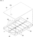
- Fig. 1 is a perspective view showing a battery pack according to an embodiment of the present disclosure.
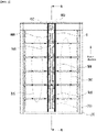
- Fig. 2 is a top view of the battery pack of Fig. 1 as viewed from above.
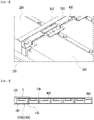
- Fig. 3 shows a section A of Fig. 1 , which is a view showing a state in which a hole is formed in the battery pack upper cover according to an embodiment of the present disclosure.
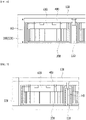
- Fig. 4 shows a section B-B of Fig. 2 , which is a cross-sectional view showing a central portion of a battery pack provided with a reflected wave absorber according to an embodiment of the present disclosure.
- the battery pack includes a plurality of first battery modules 200 and a plurality of second battery modules 300 that are arranged in two rows in a first direction, and a battery case 100 that houses the plurality of first and second battery modules 200 and 300 and includes a plurality of cross beams 110 for partitioning between the plurality of first battery modules 200 and between the plurality of second battery modules 300.
- the plurality of first battery modules 200 and the plurality of second battery modules 300 may be arranged so as to face each other.
- the battery pack includes a first wave path guide 400 that is formed to extend along a first direction at an upside part of the plurality of first battery modules 200; and a second wave path guide 500 that is formed to extend along a first direction at an upside part of the plurality of second battery modules 300.
- the battery pack includes a plurality of first slave BMSs 600 that are positioned at one side of the plurality of first battery modules 200 facing the plurality of second battery modules 300 and are arranged in the first direction between the first wave path guide 400 and the second wave path guide 500, and a plurality of second slave BMSs 700 that are positioned on one side of the plurality of second battery modules 300 facing the plurality of first battery modules 200 and are arranged in the first direction between the first wave path guide 400 and the second wave path guide 500.
- the battery case 100 houses a plurality of first and second battery modules 200 and 300.
- the plurality of module regions of the battery case 100 may be formed to have sizes corresponding to the sizes of the first and second battery modules 200 and 300, respectively.
- the plurality of first and second battery modules 200 and 300 may be seated on the plurality of module regions, respectively.
- the plurality of first battery modules 200 are arranged along a first direction, and the plurality of second battery modules 300 are arranged along a first direction at the side face of the plurality of first battery modules 200, thereby forming a two-row battery module arrangement structure.
- each battery module constituting the plurality of first battery modules 200 may be arranged apart from each other so as to face each battery module constituting the plurality of second battery modules 300.
- a cross beam 110 may be formed between module regions to partition between battery modules arranged in each module region.
- the cross beam 110 can protect the plurality of first and second battery modules 200 and 300 from the physical force acting from the outside together with the outside wall 120 forming the outer periphery of the battery case 100.
- the thermal conductive resin layer can be formed on the bottom face of the battery case 100.
- the thermal conductive resin layer can transfer the heat generated from the plurality of first and second battery modules 200 and 300 arranged in each of the plurality of module regions to the outside of the battery pack.
- the first slave BMS 600 may be arranged in each of the plurality of first battery modules 200. More specifically, the first slave BMS 600 may be arranged in portions facing the plurality of second battery modules 300. The first slave BMS 600 may be arranged in the central portion of the battery case 100. That is, the first slave BMS 600 is arranged in one side parts of the plurality of first battery modules 200 along the first direction among the plurality of first and second battery modules 200 and 300, and thus can be arranged across the central portion of the battery case 100.
- the second slave BMS 700 may be arranged in each of the plurality of second battery modules 300. More specifically, the second slave BMS 700 may be arranged in portions facing the plurality of first battery modules 200. The second slave BMS 700 may be arranged in the central portion of the battery case 100. That is, the second slave BMS 700 is arranged in one side parts of the plurality of second battery modules 300 along the first direction between the plurality of first and second battery modules 200 and 300, and thus can be arranged across the central portion of the battery case 100.
- the slave BMS is located in the central portion of the battery case as in the present embodiment, that is, in the space between the battery modules as shown in Fig. 1 , rather than the slave BMS being located on the outer hull part of the battery case.
- the battery pack according to the present embodiment includes a first wave path guide 400 formed to extend along the first direction at the upside part of the plurality of first battery modules 200, and a second wave path guide 500 formed to extend along the first direction at the upside part of the plurality of second battery modules 300.
- the first slave BMS 600 and the second slave BMS 700 according to the present embodiment may be disposed in a space formed between the first and second wave path guides 400 and 500.
- the first wave path guide 400 is formed between the battery pack upper cover 130 and the plurality of first battery modules 200
- the second wave path guide 500 may be formed between the battery pack upper cover 130 and the plurality of second battery modules 300.
- the battery pack according to the present embodiment is mainly mounted inside the electric vehicle, and the periphery of the battery pack to be mounted is made of a metal material.
- the communication performance may deteriorate due to the multi-path phenomenon of radio waves reflected by the metal material.
- the first and second wave path guides 400 and 500 can be formed so as to cover the space between the plurality of first and second battery modules 200 and 300 provided with the plurality of first and second slave BMSs 600 and 700. Therefore, it is possible to concentrate the wireless transmission signal distribution in the space between the plurality of first and second battery modules 200 and 300 formed between the first and second wave path guides 400 and 500, thereby improving the wireless transmission performance. Further, the deterioration that may occur in communication between the master BMS 800 and the first and second slave BMSs 600 and 700 can be minimized.
- the wireless transmission coefficient S21 among the S-parameters is improved by about 18dB from -53.78dB to -35.21dB to construct a stable communication connection structure, as compared with the conventional battery pack structure in which slave BMSs are arranged outside and no wave path guide is installed,
- the battery pack may further include a master BMS 800 formed separately from the plurality of first and second battery modules between the first wave path guide 400 and the second wave path guide 500.
- the master BMS 800 may communicate with a host system.
- the master BMS 800 can mainly manage communication with the plurality of first and second slave BMSs 600 and 700.
- the first and second wave path guides 400 are formed by passing through the plurality of first and second battery modules 200 and 300 and extending in the first direction up to a position where the master BMS 800 is arranged, and the master BMS 800 is arranged at a position separated from the plurality of first and second battery modules 200 and 300 in the first direction.
- the master BMS 800 may be arranged symmetrically with the plurality of first and second battery modules 200 and 300.
- the master BMS 800 is arranged at a position symmetrically separated from the plurality of first and second slave BMSs 600 and 700, so that communication with the slave BMSs can be performed in a balanced manner. Further, the master BMS 800 is arranged in the space between the first and second wave path guides 400 and 500 together with the first and second slave BMSs 600 and 700, so that communication deterioration between the master BMS 800 and the first and second slave BMS 600 and 700 can be minimized, and wireless communication performance can be secured.
- antennas can be formed in the first and second slave BMSs 600 and 700.
- the antenna may include a chip antenna. According to the experimental example, when a chip antenna is used for the first and second slave BMS 600 and 700 according to the present embodiment, it is possible to secure excellent wireless performance by 10dB or more as compared with the case of using a pattern antenna.
- the battery pack according to the present embodiment further includes a battery pack upper cover 130 that covers the upper surface of the battery case 100. At this time, at least one hole 130a may be formed in the battery pack upper cover 130.
- the heat dissipation function of the battery pack can be performed through the hole 130a formed in the battery pack upper cover 130.
- noise may occur during communication between the BMSs due to the hole 130a that connects the outside and the inside of the battery pack.
- the size of the hole 130a increases, noise may also increase. Therefore, the number and size of the holes 130a that can appropriately satisfy both the heat dissipation performance and the noise performance at the same time can be applied.
- wireless transmission performance can be secured when designing a hole diameter of 45 mm or less.
- Noise control performance can be secured when it is designed to be less than 20mm.
- a structure in which a plurality of holes having a small diameter are arranged may be advantageous. Although only one hole 130a is shown in Fig. 1 , a plurality of holes may be arranged in the battery pack upper cover 130 according to the experimental example.
- the battery pack includes a plurality of first reflected wave absorbers 1100 arranged on one side of the plurality of first battery modules 200 facing the plurality of second battery modules 300, and a plurality of second reflected wave absorbers 1200 arranged on one side of the plurality of second battery modules 300 facing the plurality of first battery modules 200.
- the transmission signal is concentrated in the space between the first and second wave path guides 400 and 500, whereby the reflected interference waves from the components provided between the first and second wave path guides 400 and 500 are generated and thus, the wireless communication performance may decrease.
- a plurality of first reflected wave absorbers 1100 can be arranged for each battery module on one side of the plurality of first battery modules 200 and thus, it is possible to absorb the reflected interference waves that may be generated from components provided between the first and second wave path guides 400 and 500, and to create an environment in which the wireless communication is not disturbed by the reflected interference waves.
- the plurality of first reflected wave absorbers 1100 may be arranged apart from the first wave path guide 400 and the first slave BMS 600 under the first wave path guide 400 and the first slave BMS 600.
- the plurality of second reflected wave absorbers 1300 may be arranged apart from the second wave path guide 500 and the second slave BMS 700 under the second wave path guide 500 and the second slave BMS 700.
- the plurality of first reflected wave absorbers 1100 may be arranged so as to correspond to the plurality of first slave BMSs 600 under the plurality of first slave BMSs 600.
- the plurality of second reflected wave absorbers 1200 may be arranged so as to correspond to the plurality of second slave BMSs 700 under the plurality of second slave BMSs 700.
- the first and second reflected wave absorbers 1100 and 1200 are arranged at positions spaced apart from the first and second slave BMSs 600 and 700, and thus, can be installed at positions that do not interfere with the wireless communication functions of the first and second slave BMSs 600 and 700.
- the first and second reflected wave absorbers 1100 and 1200 are provided inside the battery pack together with the first and second wave path guides 400 and 500, whereby in a state in which the transmission path has directionality through the first and second wave path guides 400 and 500, the reflected interference propagation can be removed through the first and second reflected wave absorbers 1100 and 1200, and thus, the wireless transmission performance of the battery pack according to the present embodiment can be maximized.
- Fig. 5 shows a section D of Fig. 2 , which is a view showing an interval between slave BMSs according to an embodiment of the present disclosure.
- the plurality of first slave BMS 600 and the plurality of second slave BMS 700 may be formed apart from each other so as to have a gap G1 as shown in Fig. 5 . More specifically, the plurality of first slave BMS 600 arranged in the plurality of first battery modules 200 and the plurality of second slave BMS 700 arranged in the plurality of second battery modules 300 may formed to be separated from each other.
- the separation distance between the first slave BMS 600 and the second slave BMS 700 may be formed to be 50 mm.
- the distance between the two battery modules arranged in two rows was arranged as narrow as 30 mm, but the distance between the two battery modules is increased to 50 mm as in the present embodiment, so that the wireless transmission space is increased, and thus the wireless transmission performance can be improved.
- Fig. 6 shows a section C of Fig. 4 , which is a view showing the height of the outside wall of the battery case according to an embodiment of the present disclosure.
- the battery pack may be configured such that the upper end of the outside wall 120 of the battery case 100 and the battery pack upper cover 130 are coupled, and the battery pack upper cover 130 may be formed apart from the plurality of first and second battery modules 200 and 300.
- the height H2 of the outside wall 120 may be formed to be 138 mm.
- the height of the outside wall is formed to be 128 mm, but according to the present embodiment, the wireless transmission performance can be improved by making the height H2 of the outside wall 120 higher than the height of the conventional outside wall. In other words, as the height H2 of the outside wall 120 increases, the wireless transmission performance can be more improved.
- Fig. 6 shows only the portion in which the plurality of first slave BMS 600 and the first wave path guide 400 are formed, but a portion in which the plurality of second slave BMS 700 and the second wave path guide 500 formed at mutually opposite sides are also arranged symmetrically as in the configuration of Fig. 6 .
- Fig. 7 shows a section C of Fig. 4 , which is a view showing a height of a cross beam of a battery case according to an embodiment of the present disclosure.
- the battery pack may include a plurality of first bus bars 910 arranged so as to span between two adjacent battery modules among each battery module of the plurality of first battery modules 200, and a plurality of second bus bars 920 arranged so as to span between two adjacent battery modules among each battery module of the plurality of second battery modules 300.
- the cross beam 110 may be formed apart from the plurality of first and second bus bars 910 and 920 under the plurality of first and second bus bars 910 and 920, respectively.
- the height of the cross beam 110 may be formed to be 70 mm.
- the height of the conventional cross beam 110 was formed to be about 90 mm, but according to the present embodiment, the height H3 of the cross beam 110 can be made lower than that of the conventional cross beam 110, thereby improving the wireless transmission performance. In other words, as the height H3 of the cross beam 110 decreases, the wireless transmission performance can be more improved.
- Fig. 7 shows only a portion in which the plurality of first slave BMS 600 and the first wave path guide 400 are formed, but a portion in which the plurality of second slave BMSs 700 and the second wave path guide 500 formed at mutually opposite sides are also symmetrically arranged as in the configuration of Fig. 6 .
- the above-mentioned battery pack can be applied to various devices.
- a device can be applied to a vehicle means such as an electric bicycle, an electric vehicle, or a hybrid vehicle, but the present disclosure is not limited thereto, and is applicable to various devices capable of using a battery module, which also falls under the scope of the present disclosure.
Landscapes
- Chemical & Material Sciences (AREA)
- Chemical Kinetics & Catalysis (AREA)
- Electrochemistry (AREA)
- General Chemical & Material Sciences (AREA)
- Engineering & Computer Science (AREA)
- Manufacturing & Machinery (AREA)
- Microelectronics & Electronic Packaging (AREA)
- Battery Mounting, Suspending (AREA)
- Details Of Aerials (AREA)
- Support Of Aerials (AREA)
Abstract
Description
- This application claims the benefit of
Korean Patent Application No. 10-2020-0131093 filed on October 12, 2020 - The present disclosure relates to a battery pack and a device including the same, and more particularly to a battery pack capable of securing the wireless transmission performance and a device including the same.
- Generally, a secondary battery capable of being charged and discharged is widely used as a battery that is a power source for wireless mobile devices. Such batteries are also in the spotlight as a power source for electric vehicles (EVs), hybrid electric vehicles (HEVs), and the like, which have been proposed as a method for solving the air pollution problem of conventional gasoline or diesel vehicles using fossil fuels. When these batteries are alternately charged and discharged, there is a need to efficiently control the charge and discharge of the battery so that the battery maintains proper operating conditions and performance.
- For this purpose, a battery management system (BMS) that manages the condition and performance of the battery is provided in the battery pack. BMS manages a battery by measuring the current, voltage, temperature, etc. of the battery and recording them in memory.
- On the other hand, as the need for a high-capacity secondary battery structure has increased recently, including the utilization of secondary batteries as an energy storage source, there is an increasing demand for a battery pack having a multi-module structure which is an assembly of battery modules in which a plurality of secondary batteries are connected in series/parallel.
- Such a battery pack having a multi-module structure may be implemented in various types of pack structures depending on the configuration of circuits, PCBs, and the like. A multi-BMS structure composed of a plurality of slave BMSs that can easily control the condition of the secondary battery and a master BMS that integrally controls the plurality of slave BMSs is mainly used.
- Conventionally, the communication between the master BMS and the slave BMS used the wired BMS method, but a wireless BMS method (WBMS, Wireless Battery Management System) has recently been in the spotlight for improvement such as cost reduction, securing of design freedom, and weight reduction. Through the wireless BMS method, the wire harness traditionally used for wired connections is unnecessary, which can bring about cost reduction and weight reduction. The weight reduction can also bring about the effect of improving the fuel efficiency of electric vehicles provided with battery packs. In addition, it is possible to remove the connector traditionally used for the wired connection, thereby reducing cost and defective rate.
- One of the most important parts of the wireless BMS method is the performance of the antenna, and the performance of the antenna may vary depending on the operating environment of the antenna. Particularly, in the case of a battery pack mounted on an electric vehicle, the size is large and the periphery is made of a metal material. Thus, a multi-path phenomenon due to reflection may occur and communication may deteriorate. Therefore, in the wireless BMS system, it may be essential to design a battery pack structure capable of minimizing the deterioration of wireless communication performance.
- It is an object of the present disclosure to provide a battery pack capable of securing the wireless transmission performance and a device including the same.
- The objects of the present disclosure are not limited to the aforementioned objects, and other objects which are not described herein should be clearly understood by those skilled in the art from the following detailed description.
- In order to achieve the above object, according to one embodiment of the present disclosure, there is provided a battery pack comprising: a plurality of first battery modules and a plurality of second battery modules that are arranged in two rows in a first direction; a battery case that houses the plurality of first and second battery modules and includes a plurality of cross beams for partitioning between the plurality of first battery modules and between the plurality of second battery modules; a plurality of first slave BMSs that are positioned at one side of the plurality of first battery modules facing the plurality of second battery modules and are arranged in the first direction; a plurality of second slave BMSs that are positioned at one side of the plurality of second battery modules facing the plurality of first battery modules and are arranged in the first direction; a plurality of first reflected wave absorbers arranged on one side of the plurality of first battery modules facing the plurality of second battery modules; and a plurality of second reflected wave absorbers arranged on one side of the plurality of second battery modules facing the plurality of first battery modules.
- The battery pack may further comprise a first wave path guide that is formed to extend along a first direction at an upside part of the plurality of first battery modules; and a second wave path guide that is formed to extend along a first direction at an upside part of the plurality of second battery modules.
- The plurality of first slave BMSs and the plurality of second battery modules may be respectively arranged in the first direction between the first wave path guide and the second wave path guide.
- The plurality of first reflected wave absorbers may be arranged apart from the first wave path guide and the first slave BMS under the first wave path guide and the first slave BMS, and the plurality of second reflected wave absorbers may be arranged apart from the second wave path guide and the second slave BMS under the second wave path guide and the second slave BMS.
- The battery pack may further comprise a master BMS formed separately from the plurality of first and second battery modules between the first wave path guide and the second wave path guide.
- The first and second wave path guides may be formed extendedly in the first direction so as to pass through the plurality of first and second battery modules, and the master BMS may be arranged at a position separated from the plurality of first and second battery modules in the first direction.
- The plurality of first reflected wave absorbers may be arranged so as to correspond to the plurality of first slave BMSs under the plurality of first slave BMSs, and the plurality of second reflected wave absorbers may be arranged so as to correspond to the plurality of second slave BMSs under the plurality of second slave BMSs.
- The first wave path guide may be formed between the battery pack upper cover and the plurality of first battery modules, and the second wave path guide may be formed between the battery pack upper cover and the plurality of second battery modules.
- An antenna may be formed in the first and second slave BMSs.
- The battery pack may further comprise a battery pack upper cover that covers the upper surface of the battery case, wherein at least one hole may be formed in the battery pack upper cover.
- The battery pack may comprise a plurality of first bus bars that are arranged so as to span between two adjacent battery modules among the battery modules of the plurality of first battery modules; and a plurality of second bus bars arranged so as to span between two adjacent battery modules among the battery modules of the plurality of second battery modules.
- According to one embodiment of the present disclosure, there is provided a device comprising the above-mentioned battery pack.
- A battery pack and a device including the same according to one embodiment of the present disclosure can provide a battery pack structure provided with a WBMS having a novel structure, thereby securing the wireless communication performance of the battery.
- The effects of the present disclosure are not limited to the effects mentioned above and additional other effects not described above will be clearly understood from the description of the appended claims by those skilled in the art.
-
-
Fig. 1 is a perspective view showing a battery pack according to an embodiment of the present disclosure; -
Fig. 2 is a top view of the battery pack ofFig. 1 as viewed from above; -
Fig. 3 shows a section A ofFig. 1 , which is a view showing a state in which a hole is formed in the battery pack upper cover according to an embodiment of the present disclosure; -
Fig. 4 shows a section B-B ofFig. 2 , which is a cross-sectional view showing a central portion of a battery pack provided with a reflected wave absorber according to an embodiment of the present disclosure; -
Fig. 5 shows a section D ofFig. 2 , which is a view showing an interval between slave BMSs according to an embodiment of the present disclosure; -
Fig. 6 shows a section C ofFig. 4 , which is a view showing the height of the outside wall of the battery case according to an embodiment of the present disclosure; and -
Fig. 7 shows a section C ofFig. 4 , which is a view showing a height of a cross beam of a battery case according to an embodiment of the present disclosure. - It should be appreciated that the exemplary embodiments, which will be described below, are illustratively described to assist in the understand the present disclosure, and the present disclosure can be variously modified to be carried out differently from the exemplary embodiments described herein. However, in the description of the present disclosure, the specific descriptions and illustrations of publicly known functions or constituent elements will be omitted when it is determined that the specific descriptions and illustrations may unnecessarily obscure the subject matter of the present disclosure. In addition, in order to help understand the present disclosure, the accompanying drawings are not illustrated based on actual scales, but parts of the constituent elements may be exaggerated in size.
- As used herein, terms such as first, second, and the like may be used to describe various components, and the components are not limited by the terms. The terms are used only to discriminate one component from another component.
- Further, the terms used herein are used only to describe specific exemplary embodiments, and are not intended to limit the scope of the present disclosure. A singular expression includes a plural expression unless they have definitely opposite meanings in the context. It should be understood that the terms "comprise", "include", and "have" as used herein are intended to designate the presence of stated features, numbers, steps, movements, constitutional elements, parts or combinations thereof, but it should be understood that they do not preclude a possibility of existence or addition of one or more other features, numbers, steps, movements, constitutional elements, parts or combinations thereof.
- Below, the battery pack provided with BMS according to one embodiment of the present disclosure will be described with reference to
Figs. 1 to 4 . -
Fig. 1 is a perspective view showing a battery pack according to an embodiment of the present disclosure.Fig. 2 is a top view of the battery pack ofFig. 1 as viewed from above.Fig. 3 shows a section A ofFig. 1 , which is a view showing a state in which a hole is formed in the battery pack upper cover according to an embodiment of the present disclosure.Fig. 4 shows a section B-B ofFig. 2 , which is a cross-sectional view showing a central portion of a battery pack provided with a reflected wave absorber according to an embodiment of the present disclosure. - Referring to
Figs. 1 to 4 , the battery pack according to one embodiment of the present disclosure includes a plurality offirst battery modules 200 and a plurality ofsecond battery modules 300 that are arranged in two rows in a first direction, and abattery case 100 that houses the plurality of first andsecond battery modules cross beams 110 for partitioning between the plurality offirst battery modules 200 and between the plurality ofsecond battery modules 300. The plurality offirst battery modules 200 and the plurality ofsecond battery modules 300 may be arranged so as to face each other. - Further, the battery pack includes a first
wave path guide 400 that is formed to extend along a first direction at an upside part of the plurality offirst battery modules 200; and a secondwave path guide 500 that is formed to extend along a first direction at an upside part of the plurality ofsecond battery modules 300. - Further, the battery pack includes a plurality of
first slave BMSs 600 that are positioned at one side of the plurality offirst battery modules 200 facing the plurality ofsecond battery modules 300 and are arranged in the first direction between the firstwave path guide 400 and the secondwave path guide 500, and a plurality ofsecond slave BMSs 700 that are positioned on one side of the plurality ofsecond battery modules 300 facing the plurality offirst battery modules 200 and are arranged in the first direction between the firstwave path guide 400 and the secondwave path guide 500. - Referring to
Fig. 1 , thebattery case 100 houses a plurality of first andsecond battery modules battery case 100 may be formed to have sizes corresponding to the sizes of the first andsecond battery modules second battery modules - According to the present embodiment, the plurality of
first battery modules 200 are arranged along a first direction, and the plurality ofsecond battery modules 300 are arranged along a first direction at the side face of the plurality offirst battery modules 200, thereby forming a two-row battery module arrangement structure. At this time, each battery module constituting the plurality offirst battery modules 200 may be arranged apart from each other so as to face each battery module constituting the plurality ofsecond battery modules 300. - Referring to
Figs. 2 and4 , across beam 110 may be formed between module regions to partition between battery modules arranged in each module region. Thecross beam 110 can protect the plurality of first andsecond battery modules outside wall 120 forming the outer periphery of thebattery case 100. - The thermal conductive resin layer can be formed on the bottom face of the
battery case 100. The thermal conductive resin layer can transfer the heat generated from the plurality of first andsecond battery modules - According to the present embodiment, the
first slave BMS 600 may be arranged in each of the plurality offirst battery modules 200. More specifically, thefirst slave BMS 600 may be arranged in portions facing the plurality ofsecond battery modules 300. Thefirst slave BMS 600 may be arranged in the central portion of thebattery case 100. That is, thefirst slave BMS 600 is arranged in one side parts of the plurality offirst battery modules 200 along the first direction among the plurality of first andsecond battery modules battery case 100. - The
second slave BMS 700 may be arranged in each of the plurality ofsecond battery modules 300. More specifically, thesecond slave BMS 700 may be arranged in portions facing the plurality offirst battery modules 200. Thesecond slave BMS 700 may be arranged in the central portion of thebattery case 100. That is, thesecond slave BMS 700 is arranged in one side parts of the plurality ofsecond battery modules 300 along the first direction between the plurality of first andsecond battery modules battery case 100. - Looking at the wireless transmission characteristics according to the arrangement position of the master BMS and the slave BMS, it may be more advantageous in terms of wireless transmission performance that the slave BMS is located in the central portion of the battery case as in the present embodiment, that is, in the space between the battery modules as shown in
Fig. 1 , rather than the slave BMS being located on the outer hull part of the battery case. - The battery pack according to the present embodiment includes a first wave path guide 400 formed to extend along the first direction at the upside part of the plurality of
first battery modules 200, and a second wave path guide 500 formed to extend along the first direction at the upside part of the plurality ofsecond battery modules 300. At this time, thefirst slave BMS 600 and thesecond slave BMS 700 according to the present embodiment may be disposed in a space formed between the first and second wave path guides 400 and 500. In addition, the first wave path guide 400 is formed between the battery packupper cover 130 and the plurality offirst battery modules 200, and the second wave path guide 500 may be formed between the battery packupper cover 130 and the plurality ofsecond battery modules 300. - The battery pack according to the present embodiment is mainly mounted inside the electric vehicle, and the periphery of the battery pack to be mounted is made of a metal material. Thus, the communication performance may deteriorate due to the multi-path phenomenon of radio waves reflected by the metal material. Thus, according to the present embodiment, the first and second wave path guides 400 and 500 can be formed so as to cover the space between the plurality of first and
second battery modules second slave BMSs second battery modules master BMS 800 and the first andsecond slave BMSs - According to the experimental example, it can be confirmed that in the battery pack in which the central arrangement structure of the first and
second slave BMS - According to the present embodiment, the battery pack may further include a
master BMS 800 formed separately from the plurality of first and second battery modules between the first wave path guide 400 and the second wave path guide 500. Themaster BMS 800 may communicate with a host system. Themaster BMS 800 can mainly manage communication with the plurality of first andsecond slave BMSs - The first and second wave path guides 400 are formed by passing through the plurality of first and
second battery modules master BMS 800 is arranged, and themaster BMS 800 is arranged at a position separated from the plurality of first andsecond battery modules master BMS 800 may be arranged symmetrically with the plurality of first andsecond battery modules - Therefore, the
master BMS 800 is arranged at a position symmetrically separated from the plurality of first andsecond slave BMSs master BMS 800 is arranged in the space between the first and second wave path guides 400 and 500 together with the first andsecond slave BMSs master BMS 800 and the first andsecond slave BMS - According to the present embodiment, antennas can be formed in the first and
second slave BMSs second slave BMS - Referring to
Fig. 1 , the battery pack according to the present embodiment further includes a battery packupper cover 130 that covers the upper surface of thebattery case 100. At this time, at least onehole 130a may be formed in the battery packupper cover 130. - The heat dissipation function of the battery pack can be performed through the
hole 130a formed in the battery packupper cover 130. However, noise may occur during communication between the BMSs due to thehole 130a that connects the outside and the inside of the battery pack. When the size of thehole 130a increases, noise may also increase. Therefore, the number and size of theholes 130a that can appropriately satisfy both the heat dissipation performance and the noise performance at the same time can be applied. According to the experimental example, as a result of investigating the wireless transmission characteristics and noise control performance, in the case of a worst case, such as a hole located directly above the antenna of the master BMS or slave BMS, or a mobile phone hotspot located near the hole, wireless transmission performance can be secured when designing a hole diameter of 45 mm or less. Noise control performance can be secured when it is designed to be less than 20mm. However, even if there are a plurality of holes, the same noise control performance can be obtained. Thus, in consideration of heat dissipation and noise performance, a structure in which a plurality of holes having a small diameter are arranged may be advantageous. Although only onehole 130a is shown inFig. 1 , a plurality of holes may be arranged in the battery packupper cover 130 according to the experimental example. - Referring to
Fig. 4 , the battery pack according to one embodiment of the present disclosure includes a plurality of first reflectedwave absorbers 1100 arranged on one side of the plurality offirst battery modules 200 facing the plurality ofsecond battery modules 300, and a plurality of second reflectedwave absorbers 1200 arranged on one side of the plurality ofsecond battery modules 300 facing the plurality offirst battery modules 200. - When an artificial propagation passage space is generated by using the first and second wave path guides 400 and 500 as in the present embodiment, the transmission signal is concentrated in the space between the first and second wave path guides 400 and 500, whereby the reflected interference waves from the components provided between the first and second wave path guides 400 and 500 are generated and thus, the wireless communication performance may decrease.
- Thus, according to the present embodiment, as shown in
Fig. 4 , a plurality of first reflectedwave absorbers 1100 can be arranged for each battery module on one side of the plurality offirst battery modules 200 and thus, it is possible to absorb the reflected interference waves that may be generated from components provided between the first and second wave path guides 400 and 500, and to create an environment in which the wireless communication is not disturbed by the reflected interference waves. - Only the configuration of the plurality of first reflected
wave absorbers 1100 provided on one side of the plurality offirst battery modules 200 is disclosed inFig. 4 , but the plurality ofsecond battery modules 300 are also symmetrically arranged with the arrangement structure of the plurality offirst battery modules 200 ofFig. 4 . Therefore, a plurality of second reflectedwave absorbers 1200 are also provided on one side of the plurality ofsecond battery modules 300, and the plurality of first reflectedwave absorbers 1100 and the plurality of second reflectedwave absorbers 1200 may be arranged symmetrically with each other. - According to the present embodiment, the plurality of first reflected
wave absorbers 1100 may be arranged apart from the first wave path guide 400 and thefirst slave BMS 600 under the first wave path guide 400 and thefirst slave BMS 600. The plurality of second reflected wave absorbers 1300 may be arranged apart from the second wave path guide 500 and thesecond slave BMS 700 under the second wave path guide 500 and thesecond slave BMS 700. - At this time, the plurality of first reflected
wave absorbers 1100 may be arranged so as to correspond to the plurality offirst slave BMSs 600 under the plurality offirst slave BMSs 600. Further, the plurality of second reflectedwave absorbers 1200 may be arranged so as to correspond to the plurality ofsecond slave BMSs 700 under the plurality ofsecond slave BMSs 700. - In this manner, the first and second reflected
wave absorbers second slave BMSs second slave BMSs wave absorbers wave absorbers -
Fig. 5 shows a section D ofFig. 2 , which is a view showing an interval between slave BMSs according to an embodiment of the present disclosure. - According to the present embodiment, the plurality of
first slave BMS 600 and the plurality ofsecond slave BMS 700 may be formed apart from each other so as to have a gap G1 as shown inFig. 5 . More specifically, the plurality offirst slave BMS 600 arranged in the plurality offirst battery modules 200 and the plurality ofsecond slave BMS 700 arranged in the plurality ofsecond battery modules 300 may formed to be separated from each other. - According to the present embodiment, the separation distance between the
first slave BMS 600 and thesecond slave BMS 700 may be formed to be 50 mm. Conventionally, the distance between the two battery modules arranged in two rows was arranged as narrow as 30 mm, but the distance between the two battery modules is increased to 50 mm as in the present embodiment, so that the wireless transmission space is increased, and thus the wireless transmission performance can be improved. -
Fig. 6 shows a section C ofFig. 4 , which is a view showing the height of the outside wall of the battery case according to an embodiment of the present disclosure. - Referring to
Fig. 6 , the battery pack according to one embodiment of the present disclosure may be configured such that the upper end of theoutside wall 120 of thebattery case 100 and the battery packupper cover 130 are coupled, and the battery packupper cover 130 may be formed apart from the plurality of first andsecond battery modules - According to the present embodiment, the height H2 of the
outside wall 120 may be formed to be 138 mm. Conventionally, the height of the outside wall is formed to be 128 mm, but according to the present embodiment, the wireless transmission performance can be improved by making the height H2 of theoutside wall 120 higher than the height of the conventional outside wall. In other words, as the height H2 of theoutside wall 120 increases, the wireless transmission performance can be more improved. -
Fig. 6 shows only the portion in which the plurality offirst slave BMS 600 and the first wave path guide 400 are formed, but a portion in which the plurality ofsecond slave BMS 700 and the second wave path guide 500 formed at mutually opposite sides are also arranged symmetrically as in the configuration ofFig. 6 . -
Fig. 7 shows a section C ofFig. 4 , which is a view showing a height of a cross beam of a battery case according to an embodiment of the present disclosure. - Referring to
Figs. 3 and7 , the battery pack according to one embodiment of the present disclosure may include a plurality of first bus bars 910 arranged so as to span between two adjacent battery modules among each battery module of the plurality offirst battery modules 200, and a plurality of second bus bars 920 arranged so as to span between two adjacent battery modules among each battery module of the plurality ofsecond battery modules 300. At this time, thecross beam 110 may be formed apart from the plurality of first and second bus bars 910 and 920 under the plurality of first and second bus bars 910 and 920, respectively. - According to the present embodiment, the height of the
cross beam 110 may be formed to be 70 mm. The height of theconventional cross beam 110 was formed to be about 90 mm, but according to the present embodiment, the height H3 of thecross beam 110 can be made lower than that of theconventional cross beam 110, thereby improving the wireless transmission performance. In other words, as the height H3 of thecross beam 110 decreases, the wireless transmission performance can be more improved. -
Fig. 7 shows only a portion in which the plurality offirst slave BMS 600 and the first wave path guide 400 are formed, but a portion in which the plurality ofsecond slave BMSs 700 and the second wave path guide 500 formed at mutually opposite sides are also symmetrically arranged as in the configuration ofFig. 6 . - The above-mentioned battery pack can be applied to various devices. Such a device can be applied to a vehicle means such as an electric bicycle, an electric vehicle, or a hybrid vehicle, but the present disclosure is not limited thereto, and is applicable to various devices capable of using a battery module, which also falls under the scope of the present disclosure.
- Although the invention has been shown and described above with reference to the preferred embodiments, the scope of the present disclosure is not limited thereto, and numerous other modifications and embodiments can be devised by those skilled in the art, which will fall within the spirit and scope of the principles of the invention described in the appended claims. Further, these modified embodiments should not be understood individually from the technical spirit or perspective of the present disclosure.
-
- 100: battery case
- 110: cross beam
- 120: outside wall
- 130: battery pack upper cover
- 130a: hole
- 200: first battery module
- 300: second battery module
- 400: first wave path guide
- 500: second wave path guide
- 600: first slave BMS
- 700: second slave BMS
- 800: master BMS
- 910: first bus bar
- 920: second bus bar
- 1100: first reflected wave absorber
- 1200: second reflected wave absorber
Claims (12)
- A battery pack comprising:a plurality of first battery modules and a plurality of second battery modules that are arranged in two rows in a first direction;a battery case that houses the plurality of first and second battery modules and includes a plurality of cross beams for partitioning between the plurality of first battery modules and between the plurality of second battery modules;a plurality of first slave BMSs that are positioned at one side of the plurality of first battery modules facing the plurality of second battery modules and are arranged in the first direction;a plurality of second slave BMSs that are positioned at one side of the plurality of second battery modules facing the plurality of first battery modules and are arranged in the first direction;a plurality of first reflected wave absorbers arranged on one side of the plurality of first battery modules facing the plurality of second battery modules; anda plurality of second reflected wave absorbers arranged on one side of the plurality of second battery modules facing the plurality of first battery modules.
- The battery pack of claim 1,which further comprises a first wave path guide that is formed to extend along a first direction at an upside part of the plurality of first battery modules; anda second wave path guide that is formed to extend along a first direction at an upside part of the plurality of second battery modules.
- The battery pack of claim 2, wherein:
the plurality of first slave BMSs and the plurality of second battery modules are respectively arranged in the first direction between the first wave path guide and the second wave path guide. - The battery pack of claim 3, wherein:the plurality of first reflected wave absorbers are arranged apart from the first wave path guide and the first slave BMS under the first wave path guide and the first slave BMS, andthe plurality of second reflected wave absorbers are arranged apart from the second wave path guide and the second slave BMS under the second wave path guide and the second slave BMS.
- The battery pack of claim 2, wherein:which further comprises a master BMS formed separately from the plurality of first and second battery modules between the first wave path guide and the second wave path guide.
- The battery pack of claim 5, wherein:the first and second wave path guides are formed extendedly in the first direction so as to pass through the plurality of first and second battery modules, andthe master BMS is arranged at a position separated from the plurality of first and second battery modules in the first direction.
- The battery pack of claim 5, wherein:the plurality of first reflected wave absorbers are arranged so as to correspond to the plurality of first slave BMSs under the plurality of first slave BMSs, andthe plurality of second reflected wave absorbers are arranged so as to correspond to the plurality of second slave BMSs under the plurality of second slave BMSs.
- The battery pack of claim 2, wherein:the first wave path guide is formed between the battery pack upper cover and the plurality of first battery modules, andthe second wave path guide is formed between the battery pack upper cover and the plurality of second battery modules.
- The battery pack of claim 1, wherein:
an antenna is formed in the first and second slave BMSs. - The battery pack of claim 1, wherein:which further comprises a battery pack upper cover that covers the upper surface of the battery case,wherein at least one hole is formed in the battery pack upper cover.
- The battery pack of claim 1, wherein:which comprises a plurality of first bus bars that are arranged so as to span between two adjacent battery modules among the battery modules of the plurality of first battery modules; anda plurality of second bus bars arranged so as to span between two adjacent battery modules among the battery modules of the plurality of second battery modules.
- A device comprising the battery pack of claim 1.
Applications Claiming Priority (2)
| Application Number | Priority Date | Filing Date | Title |
|---|---|---|---|
| KR1020200131093A KR102837606B1 (en) | 2020-10-12 | 2020-10-12 | Battery pack and device including the same |
| PCT/KR2021/013818 WO2022080760A1 (en) | 2020-10-12 | 2021-10-07 | Battery pack and device including same |
Publications (3)
| Publication Number | Publication Date |
|---|---|
| EP4053964A1 true EP4053964A1 (en) | 2022-09-07 |
| EP4053964A4 EP4053964A4 (en) | 2024-06-19 |
| EP4053964B1 EP4053964B1 (en) | 2025-06-25 |
Family
ID=81208453
Family Applications (1)
| Application Number | Title | Priority Date | Filing Date |
|---|---|---|---|
| EP21880407.8A Active EP4053964B1 (en) | 2020-10-12 | 2021-10-07 | Battery pack and device including the same |
Country Status (8)
| Country | Link |
|---|---|
| US (1) | US20220376311A1 (en) |
| EP (1) | EP4053964B1 (en) |
| JP (1) | JP7387207B2 (en) |
| KR (1) | KR102837606B1 (en) |
| CN (1) | CN114902467B (en) |
| ES (1) | ES3037500T3 (en) |
| HU (1) | HUE072589T2 (en) |
| WO (1) | WO2022080760A1 (en) |
Families Citing this family (2)
| Publication number | Priority date | Publication date | Assignee | Title |
|---|---|---|---|---|
| KR102864404B1 (en) * | 2024-01-11 | 2025-09-25 | 주식회사 엘지에너지솔루션 | Battery pack |
| KR102862710B1 (en) * | 2024-03-28 | 2025-09-23 | 주식회사 엘지에너지솔루션 | Battery pack |
Family Cites Families (20)
| Publication number | Priority date | Publication date | Assignee | Title |
|---|---|---|---|---|
| US6579404B2 (en) * | 2001-01-23 | 2003-06-17 | Northrop Grumman Corporation | Method of making precision geometry advanced composite honeycomb material for spacecraft applications and honeycomb material made thereby |
| US6919516B2 (en) * | 2002-01-08 | 2005-07-19 | Mettler-Toledo | RF multiple load cell scale |
| BR112013030925B8 (en) * | 2011-05-31 | 2023-03-21 | Lg Chemical Ltd | ENERGY STORAGE SYSTEM HAVING MODULARIZED EMS CONNECTION STRUCTURE AND METHOD FOR CONTROLLING THE SYSTEM |
| KR101768251B1 (en) * | 2013-04-05 | 2017-08-30 | 삼성에스디아이 주식회사 | Battery Pack Providing Confirmation For Normal Connection Of Battery Module |
| WO2015189898A1 (en) * | 2014-06-09 | 2015-12-17 | 日立オートモティブシステムズ株式会社 | Battery system |
| JP6256397B2 (en) * | 2015-03-23 | 2018-01-10 | トヨタ自動車株式会社 | Battery pack |
| KR101776853B1 (en) * | 2015-06-30 | 2017-09-12 | 인지컨트롤스 주식회사 | Battery pack |
| US10050316B2 (en) * | 2016-05-13 | 2018-08-14 | Infineon Technologies Ag | Communication between battery cells |
| KR102176853B1 (en) * | 2016-07-22 | 2020-11-10 | 주식회사 엘지화학 | Battery wireless control system and method |
| KR102172517B1 (en) * | 2017-04-04 | 2020-10-30 | 주식회사 엘지화학 | Battery Pack having crash beam structure |
| KR102155331B1 (en) * | 2017-07-06 | 2020-09-11 | 주식회사 엘지화학 | Wireless battery manamement system and a battery pack including the same |
| KR102202615B1 (en) * | 2017-09-25 | 2021-01-12 | 주식회사 엘지화학 | Apparatus for assigning identification information to a plurality of slave battery management units |
| US10777851B2 (en) * | 2018-02-15 | 2020-09-15 | Maxim Integrated Products, Inc. | Multipoint communication systems for battery management systems, and associated systems and methods |
| JP7360763B2 (en) * | 2019-09-06 | 2023-10-13 | Apb株式会社 | assembled battery |
| JP7375581B2 (en) | 2020-01-28 | 2023-11-08 | 株式会社デンソー | battery pack |
| JP7215445B2 (en) * | 2020-02-20 | 2023-01-31 | 株式会社デンソー | battery module |
| CN111224039B (en) * | 2020-04-22 | 2020-07-24 | 江苏时代新能源科技有限公司 | Casing, group battery and device |
| JP7161504B2 (en) * | 2020-05-26 | 2022-10-26 | Apb株式会社 | cell unit |
| KR102939839B1 (en) | 2020-06-02 | 2026-03-13 | 주식회사 엘지에너지솔루션 | A battery rack with optimization structure for wireless communication and energy storage device including the same |
| US20230318094A1 (en) * | 2020-08-06 | 2023-10-05 | Apb Corporation | Battery Cell |
-
2020
- 2020-10-12 KR KR1020200131093A patent/KR102837606B1/en active Active
-
2021
- 2021-10-07 HU HUE21880407A patent/HUE072589T2/en unknown
- 2021-10-07 JP JP2022533201A patent/JP7387207B2/en active Active
- 2021-10-07 EP EP21880407.8A patent/EP4053964B1/en active Active
- 2021-10-07 CN CN202180007904.5A patent/CN114902467B/en active Active
- 2021-10-07 US US17/785,275 patent/US20220376311A1/en active Pending
- 2021-10-07 WO PCT/KR2021/013818 patent/WO2022080760A1/en not_active Ceased
- 2021-10-07 ES ES21880407T patent/ES3037500T3/en active Active
Also Published As
| Publication number | Publication date |
|---|---|
| EP4053964B1 (en) | 2025-06-25 |
| US20220376311A1 (en) | 2022-11-24 |
| ES3037500T3 (en) | 2025-10-02 |
| EP4053964A4 (en) | 2024-06-19 |
| KR102837606B1 (en) | 2025-07-22 |
| JP7387207B2 (en) | 2023-11-28 |
| KR20220048214A (en) | 2022-04-19 |
| CN114902467B (en) | 2025-07-15 |
| HUE072589T2 (en) | 2025-11-28 |
| JP2023505470A (en) | 2023-02-09 |
| WO2022080760A1 (en) | 2022-04-21 |
| CN114902467A (en) | 2022-08-12 |
Similar Documents
| Publication | Publication Date | Title |
|---|---|---|
| EP4071884A1 (en) | Battery pack and device including same | |
| EP4224604A1 (en) | Cell assembly to which longitudinal extension structure of pouch-type battery cell is applied, and battery pack comprising same | |
| US12166240B2 (en) | Battery module and battery pack including the same | |
| EP2706589B1 (en) | Battery module and battery assembly including same | |
| US12176496B2 (en) | Battery module and battery pack including the same | |
| JP7666490B2 (en) | Battery Module | |
| JP7744425B2 (en) | Battery pack and automobile including same | |
| EP4053964B1 (en) | Battery pack and device including the same | |
| EP3761396A1 (en) | Battery module including protective cover for covering flexible printed circuit board | |
| EP4203150B1 (en) | Battery module and battery pack comprising the same | |
| US12597672B2 (en) | Battery module and battery pack including the same | |
| EP3067962A1 (en) | Battery pack | |
| JP7159984B2 (en) | battery module | |
| KR102874309B1 (en) | battery module | |
| KR20260011501A (en) | A battery pack capable of forced discharge | |
| KR20250112612A (en) | Battery pack and vehicle comprising the battery pack | |
| CN120476508A (en) | Battery pack and vehicle including the same |
Legal Events
| Date | Code | Title | Description |
|---|---|---|---|
| STAA | Information on the status of an ep patent application or granted ep patent |
Free format text: STATUS: THE INTERNATIONAL PUBLICATION HAS BEEN MADE |
|
| PUAI | Public reference made under article 153(3) epc to a published international application that has entered the european phase |
Free format text: ORIGINAL CODE: 0009012 |
|
| STAA | Information on the status of an ep patent application or granted ep patent |
Free format text: STATUS: REQUEST FOR EXAMINATION WAS MADE |
|
| 17P | Request for examination filed |
Effective date: 20220531 |
|
| AK | Designated contracting states |
Kind code of ref document: A1 Designated state(s): AL AT BE BG CH CY CZ DE DK EE ES FI FR GB GR HR HU IE IS IT LI LT LU LV MC MK MT NL NO PL PT RO RS SE SI SK SM TR |
|
| DAV | Request for validation of the european patent (deleted) | ||
| DAX | Request for extension of the european patent (deleted) | ||
| A4 | Supplementary search report drawn up and despatched |
Effective date: 20240522 |
|
| RIC1 | Information provided on ipc code assigned before grant |
Ipc: H01M 50/209 20210101ALI20240515BHEP Ipc: H01M 50/502 20210101ALI20240515BHEP Ipc: H01M 50/20 20210101ALI20240515BHEP Ipc: H01M 10/42 20060101AFI20240515BHEP |
|
| GRAP | Despatch of communication of intention to grant a patent |
Free format text: ORIGINAL CODE: EPIDOSNIGR1 |
|
| STAA | Information on the status of an ep patent application or granted ep patent |
Free format text: STATUS: GRANT OF PATENT IS INTENDED |
|
| RIC1 | Information provided on ipc code assigned before grant |
Ipc: H01M 50/209 20210101ALI20250203BHEP Ipc: H01M 50/502 20210101ALI20250203BHEP Ipc: H01M 50/20 20210101ALI20250203BHEP Ipc: H01M 10/42 20060101AFI20250203BHEP |
|
| INTG | Intention to grant announced |
Effective date: 20250219 |
|
| P01 | Opt-out of the competence of the unified patent court (upc) registered |
Free format text: CASE NUMBER: APP_13955/2025 Effective date: 20250321 |
|
| GRAS | Grant fee paid |
Free format text: ORIGINAL CODE: EPIDOSNIGR3 |
|
| GRAA | (expected) grant |
Free format text: ORIGINAL CODE: 0009210 |
|
| STAA | Information on the status of an ep patent application or granted ep patent |
Free format text: STATUS: THE PATENT HAS BEEN GRANTED |
|
| AK | Designated contracting states |
Kind code of ref document: B1 Designated state(s): AL AT BE BG CH CY CZ DE DK EE ES FI FR GB GR HR HU IE IS IT LI LT LU LV MC MK MT NL NO PL PT RO RS SE SI SK SM TR |
|
| REG | Reference to a national code |
Ref country code: GB Ref legal event code: FG4D |
|
| REG | Reference to a national code |
Ref country code: CH Ref legal event code: EP |
|
| REG | Reference to a national code |
Ref country code: CH Ref legal event code: EP |
|
| REG | Reference to a national code |
Ref country code: IE Ref legal event code: FG4D |
|
| REG | Reference to a national code |
Ref country code: DE Ref legal event code: R096 Ref document number: 602021033069 Country of ref document: DE |
|
| REG | Reference to a national code |
Ref country code: ES Ref legal event code: FG2A Ref document number: 3037500 Country of ref document: ES Kind code of ref document: T3 Effective date: 20251002 |
|
| PG25 | Lapsed in a contracting state [announced via postgrant information from national office to epo] |
Ref country code: FI Free format text: LAPSE BECAUSE OF FAILURE TO SUBMIT A TRANSLATION OF THE DESCRIPTION OR TO PAY THE FEE WITHIN THE PRESCRIBED TIME-LIMIT Effective date: 20250625 |
|
| REG | Reference to a national code |
Ref country code: LT Ref legal event code: MG9D |
|
| PG25 | Lapsed in a contracting state [announced via postgrant information from national office to epo] |
Ref country code: NO Free format text: LAPSE BECAUSE OF FAILURE TO SUBMIT A TRANSLATION OF THE DESCRIPTION OR TO PAY THE FEE WITHIN THE PRESCRIBED TIME-LIMIT Effective date: 20250925 Ref country code: GR Free format text: LAPSE BECAUSE OF FAILURE TO SUBMIT A TRANSLATION OF THE DESCRIPTION OR TO PAY THE FEE WITHIN THE PRESCRIBED TIME-LIMIT Effective date: 20250926 |
|
| PG25 | Lapsed in a contracting state [announced via postgrant information from national office to epo] |
Ref country code: BG Free format text: LAPSE BECAUSE OF FAILURE TO SUBMIT A TRANSLATION OF THE DESCRIPTION OR TO PAY THE FEE WITHIN THE PRESCRIBED TIME-LIMIT Effective date: 20250625 |
|
| PGFP | Annual fee paid to national office [announced via postgrant information from national office to epo] |
Ref country code: GB Payment date: 20250922 Year of fee payment: 5 Ref country code: BE Payment date: 20250922 Year of fee payment: 5 |
|
| PG25 | Lapsed in a contracting state [announced via postgrant information from national office to epo] |
Ref country code: HR Free format text: LAPSE BECAUSE OF FAILURE TO SUBMIT A TRANSLATION OF THE DESCRIPTION OR TO PAY THE FEE WITHIN THE PRESCRIBED TIME-LIMIT Effective date: 20250625 |
|
| PGFP | Annual fee paid to national office [announced via postgrant information from national office to epo] |
Ref country code: FR Payment date: 20250925 Year of fee payment: 5 |
|
| PG25 | Lapsed in a contracting state [announced via postgrant information from national office to epo] |
Ref country code: RS Free format text: LAPSE BECAUSE OF FAILURE TO SUBMIT A TRANSLATION OF THE DESCRIPTION OR TO PAY THE FEE WITHIN THE PRESCRIBED TIME-LIMIT Effective date: 20250925 |
|
| PG25 | Lapsed in a contracting state [announced via postgrant information from national office to epo] |
Ref country code: LV Free format text: LAPSE BECAUSE OF FAILURE TO SUBMIT A TRANSLATION OF THE DESCRIPTION OR TO PAY THE FEE WITHIN THE PRESCRIBED TIME-LIMIT Effective date: 20250625 |
|
| REG | Reference to a national code |
Ref country code: NL Ref legal event code: MP Effective date: 20250625 |
|
| PGFP | Annual fee paid to national office [announced via postgrant information from national office to epo] |
Ref country code: HU Payment date: 20251029 Year of fee payment: 5 |
|
| PG25 | Lapsed in a contracting state [announced via postgrant information from national office to epo] |
Ref country code: NL Free format text: LAPSE BECAUSE OF FAILURE TO SUBMIT A TRANSLATION OF THE DESCRIPTION OR TO PAY THE FEE WITHIN THE PRESCRIBED TIME-LIMIT Effective date: 20250625 |
|
| REG | Reference to a national code |
Ref country code: HU Ref legal event code: AG4A Ref document number: E072589 Country of ref document: HU |
|
| PG25 | Lapsed in a contracting state [announced via postgrant information from national office to epo] |
Ref country code: PT Free format text: LAPSE BECAUSE OF FAILURE TO SUBMIT A TRANSLATION OF THE DESCRIPTION OR TO PAY THE FEE WITHIN THE PRESCRIBED TIME-LIMIT Effective date: 20251027 |
|
| REG | Reference to a national code |
Ref country code: AT Ref legal event code: MK05 Ref document number: 1807538 Country of ref document: AT Kind code of ref document: T Effective date: 20250625 |
|
| PG25 | Lapsed in a contracting state [announced via postgrant information from national office to epo] |
Ref country code: IS Free format text: LAPSE BECAUSE OF FAILURE TO SUBMIT A TRANSLATION OF THE DESCRIPTION OR TO PAY THE FEE WITHIN THE PRESCRIBED TIME-LIMIT Effective date: 20251025 |
|
| PGFP | Annual fee paid to national office [announced via postgrant information from national office to epo] |
Ref country code: DE Payment date: 20250922 Year of fee payment: 5 |
|
| PG25 | Lapsed in a contracting state [announced via postgrant information from national office to epo] |
Ref country code: AT Free format text: LAPSE BECAUSE OF FAILURE TO SUBMIT A TRANSLATION OF THE DESCRIPTION OR TO PAY THE FEE WITHIN THE PRESCRIBED TIME-LIMIT Effective date: 20250625 Ref country code: SM Free format text: LAPSE BECAUSE OF FAILURE TO SUBMIT A TRANSLATION OF THE DESCRIPTION OR TO PAY THE FEE WITHIN THE PRESCRIBED TIME-LIMIT Effective date: 20250625 |
|
| PG25 | Lapsed in a contracting state [announced via postgrant information from national office to epo] |
Ref country code: CZ Free format text: LAPSE BECAUSE OF FAILURE TO SUBMIT A TRANSLATION OF THE DESCRIPTION OR TO PAY THE FEE WITHIN THE PRESCRIBED TIME-LIMIT Effective date: 20250625 |
|
| PG25 | Lapsed in a contracting state [announced via postgrant information from national office to epo] |
Ref country code: PL Free format text: LAPSE BECAUSE OF FAILURE TO SUBMIT A TRANSLATION OF THE DESCRIPTION OR TO PAY THE FEE WITHIN THE PRESCRIBED TIME-LIMIT Effective date: 20250625 |
|
| PG25 | Lapsed in a contracting state [announced via postgrant information from national office to epo] |
Ref country code: EE Free format text: LAPSE BECAUSE OF FAILURE TO SUBMIT A TRANSLATION OF THE DESCRIPTION OR TO PAY THE FEE WITHIN THE PRESCRIBED TIME-LIMIT Effective date: 20250625 |
|
| PG25 | Lapsed in a contracting state [announced via postgrant information from national office to epo] |
Ref country code: SK Free format text: LAPSE BECAUSE OF FAILURE TO SUBMIT A TRANSLATION OF THE DESCRIPTION OR TO PAY THE FEE WITHIN THE PRESCRIBED TIME-LIMIT Effective date: 20250625 |
|
| PGFP | Annual fee paid to national office [announced via postgrant information from national office to epo] |
Ref country code: ES Payment date: 20251117 Year of fee payment: 5 |
|
| PG25 | Lapsed in a contracting state [announced via postgrant information from national office to epo] |
Ref country code: RO Free format text: LAPSE BECAUSE OF FAILURE TO SUBMIT A TRANSLATION OF THE DESCRIPTION OR TO PAY THE FEE WITHIN THE PRESCRIBED TIME-LIMIT Effective date: 20250625 |
|
| PG25 | Lapsed in a contracting state [announced via postgrant information from national office to epo] |
Ref country code: DK Free format text: LAPSE BECAUSE OF FAILURE TO SUBMIT A TRANSLATION OF THE DESCRIPTION OR TO PAY THE FEE WITHIN THE PRESCRIBED TIME-LIMIT Effective date: 20250625 |
|
| PG25 | Lapsed in a contracting state [announced via postgrant information from national office to epo] |
Ref country code: IT Free format text: LAPSE BECAUSE OF FAILURE TO SUBMIT A TRANSLATION OF THE DESCRIPTION OR TO PAY THE FEE WITHIN THE PRESCRIBED TIME-LIMIT Effective date: 20250625 |
|
| PLBE | No opposition filed within time limit |
Free format text: ORIGINAL CODE: 0009261 |
|
| STAA | Information on the status of an ep patent application or granted ep patent |
Free format text: STATUS: NO OPPOSITION FILED WITHIN TIME LIMIT |