EP4053930A1 - Device for manufacturing membrane-electrode gasket assembly - Google Patents
Device for manufacturing membrane-electrode gasket assembly Download PDFInfo
- Publication number
- EP4053930A1 EP4053930A1 EP21196608.0A EP21196608A EP4053930A1 EP 4053930 A1 EP4053930 A1 EP 4053930A1 EP 21196608 A EP21196608 A EP 21196608A EP 4053930 A1 EP4053930 A1 EP 4053930A1
- Authority
- EP
- European Patent Office
- Prior art keywords
- membrane
- assembly
- sub
- electrode
- gasket
- Prior art date
- Legal status (The legal status is an assumption and is not a legal conclusion. Google has not performed a legal analysis and makes no representation as to the accuracy of the status listed.)
- Granted
Links
Images

Classifications
-
- H—ELECTRICITY
- H01—ELECTRIC ELEMENTS
- H01M—PROCESSES OR MEANS, e.g. BATTERIES, FOR THE DIRECT CONVERSION OF CHEMICAL ENERGY INTO ELECTRICAL ENERGY
- H01M8/00—Fuel cells; Manufacture thereof
- H01M8/10—Fuel cells with solid electrolytes
- H01M8/1004—Fuel cells with solid electrolytes characterised by membrane-electrode assemblies [MEA]
-
- B—PERFORMING OPERATIONS; TRANSPORTING
- B05—SPRAYING OR ATOMISING IN GENERAL; APPLYING FLUENT MATERIALS TO SURFACES, IN GENERAL
- B05C—APPARATUS FOR APPLYING FLUENT MATERIALS TO SURFACES, IN GENERAL
- B05C5/00—Apparatus in which liquid or other fluent material is projected, poured or allowed to flow on to the surface of the work
- B05C5/02—Apparatus in which liquid or other fluent material is projected, poured or allowed to flow on to the surface of the work the liquid or other fluent material being discharged through an outlet orifice by pressure, e.g. from an outlet device in contact or almost in contact, with the work
- B05C5/0254—Coating heads with slot-shaped outlet
-
- B—PERFORMING OPERATIONS; TRANSPORTING
- B05—SPRAYING OR ATOMISING IN GENERAL; APPLYING FLUENT MATERIALS TO SURFACES, IN GENERAL
- B05C—APPARATUS FOR APPLYING FLUENT MATERIALS TO SURFACES, IN GENERAL
- B05C9/00—Apparatus or plant for applying liquid or other fluent material to surfaces by means not covered by any preceding group, or in which the means of applying the liquid or other fluent material is not important
- B05C9/08—Apparatus or plant for applying liquid or other fluent material to surfaces by means not covered by any preceding group, or in which the means of applying the liquid or other fluent material is not important for applying liquid or other fluent material and performing an auxiliary operation
- B05C9/12—Apparatus or plant for applying liquid or other fluent material to surfaces by means not covered by any preceding group, or in which the means of applying the liquid or other fluent material is not important for applying liquid or other fluent material and performing an auxiliary operation the auxiliary operation being performed after the application
-
- B—PERFORMING OPERATIONS; TRANSPORTING
- B05—SPRAYING OR ATOMISING IN GENERAL; APPLYING FLUENT MATERIALS TO SURFACES, IN GENERAL
- B05C—APPARATUS FOR APPLYING FLUENT MATERIALS TO SURFACES, IN GENERAL
- B05C9/00—Apparatus or plant for applying liquid or other fluent material to surfaces by means not covered by any preceding group, or in which the means of applying the liquid or other fluent material is not important
- B05C9/08—Apparatus or plant for applying liquid or other fluent material to surfaces by means not covered by any preceding group, or in which the means of applying the liquid or other fluent material is not important for applying liquid or other fluent material and performing an auxiliary operation
- B05C9/14—Apparatus or plant for applying liquid or other fluent material to surfaces by means not covered by any preceding group, or in which the means of applying the liquid or other fluent material is not important for applying liquid or other fluent material and performing an auxiliary operation the auxiliary operation involving heating or cooling
-
- B—PERFORMING OPERATIONS; TRANSPORTING
- B32—LAYERED PRODUCTS
- B32B—LAYERED PRODUCTS, i.e. PRODUCTS BUILT-UP OF STRATA OF FLAT OR NON-FLAT, e.g. CELLULAR OR HONEYCOMB, FORM
- B32B37/00—Methods or apparatus for laminating, e.g. by curing or by ultrasonic bonding
- B32B37/0046—Methods or apparatus for laminating, e.g. by curing or by ultrasonic bonding characterised by constructional aspects of the apparatus
- B32B37/0053—Constructional details of laminating machines comprising rollers; Constructional features of the rollers
-
- B—PERFORMING OPERATIONS; TRANSPORTING
- B32—LAYERED PRODUCTS
- B32B—LAYERED PRODUCTS, i.e. PRODUCTS BUILT-UP OF STRATA OF FLAT OR NON-FLAT, e.g. CELLULAR OR HONEYCOMB, FORM
- B32B41/00—Arrangements for controlling or monitoring lamination processes; Safety arrangements
-
- H—ELECTRICITY
- H01—ELECTRIC ELEMENTS
- H01M—PROCESSES OR MEANS, e.g. BATTERIES, FOR THE DIRECT CONVERSION OF CHEMICAL ENERGY INTO ELECTRICAL ENERGY
- H01M4/00—Electrodes
- H01M4/02—Electrodes composed of, or comprising, active material
- H01M4/04—Processes of manufacture in general
- H01M4/0402—Methods of deposition of the material
- H01M4/0407—Methods of deposition of the material by coating on an electrolyte layer
-
- H—ELECTRICITY
- H01—ELECTRIC ELEMENTS
- H01M—PROCESSES OR MEANS, e.g. BATTERIES, FOR THE DIRECT CONVERSION OF CHEMICAL ENERGY INTO ELECTRICAL ENERGY
- H01M4/00—Electrodes
- H01M4/02—Electrodes composed of, or comprising, active material
- H01M4/04—Processes of manufacture in general
- H01M4/0402—Methods of deposition of the material
- H01M4/0419—Methods of deposition of the material involving spraying
-
- H—ELECTRICITY
- H01—ELECTRIC ELEMENTS
- H01M—PROCESSES OR MEANS, e.g. BATTERIES, FOR THE DIRECT CONVERSION OF CHEMICAL ENERGY INTO ELECTRICAL ENERGY
- H01M4/00—Electrodes
- H01M4/86—Inert electrodes with catalytic activity, e.g. for fuel cells
- H01M4/88—Processes of manufacture
- H01M4/8803—Supports for the deposition of the catalytic active composition
- H01M4/881—Electrolytic membranes
-
- H—ELECTRICITY
- H01—ELECTRIC ELEMENTS
- H01M—PROCESSES OR MEANS, e.g. BATTERIES, FOR THE DIRECT CONVERSION OF CHEMICAL ENERGY INTO ELECTRICAL ENERGY
- H01M4/00—Electrodes
- H01M4/86—Inert electrodes with catalytic activity, e.g. for fuel cells
- H01M4/88—Processes of manufacture
- H01M4/8803—Supports for the deposition of the catalytic active composition
- H01M4/8814—Temporary supports, e.g. decal
-
- H—ELECTRICITY
- H01—ELECTRIC ELEMENTS
- H01M—PROCESSES OR MEANS, e.g. BATTERIES, FOR THE DIRECT CONVERSION OF CHEMICAL ENERGY INTO ELECTRICAL ENERGY
- H01M4/00—Electrodes
- H01M4/86—Inert electrodes with catalytic activity, e.g. for fuel cells
- H01M4/88—Processes of manufacture
- H01M4/8825—Methods for deposition of the catalytic active composition
- H01M4/8828—Coating with slurry or ink
-
- H—ELECTRICITY
- H01—ELECTRIC ELEMENTS
- H01M—PROCESSES OR MEANS, e.g. BATTERIES, FOR THE DIRECT CONVERSION OF CHEMICAL ENERGY INTO ELECTRICAL ENERGY
- H01M4/00—Electrodes
- H01M4/86—Inert electrodes with catalytic activity, e.g. for fuel cells
- H01M4/88—Processes of manufacture
- H01M4/8878—Treatment steps after deposition of the catalytic active composition or after shaping of the electrode being free-standing body
-
- H—ELECTRICITY
- H01—ELECTRIC ELEMENTS
- H01M—PROCESSES OR MEANS, e.g. BATTERIES, FOR THE DIRECT CONVERSION OF CHEMICAL ENERGY INTO ELECTRICAL ENERGY
- H01M4/00—Electrodes
- H01M4/86—Inert electrodes with catalytic activity, e.g. for fuel cells
- H01M4/88—Processes of manufacture
- H01M4/8878—Treatment steps after deposition of the catalytic active composition or after shaping of the electrode being free-standing body
- H01M4/8882—Heat treatment, e.g. drying, baking
-
- H—ELECTRICITY
- H01—ELECTRIC ELEMENTS
- H01M—PROCESSES OR MEANS, e.g. BATTERIES, FOR THE DIRECT CONVERSION OF CHEMICAL ENERGY INTO ELECTRICAL ENERGY
- H01M4/00—Electrodes
- H01M4/86—Inert electrodes with catalytic activity, e.g. for fuel cells
- H01M4/88—Processes of manufacture
- H01M4/8878—Treatment steps after deposition of the catalytic active composition or after shaping of the electrode being free-standing body
- H01M4/8896—Pressing, rolling, calendering
-
- H—ELECTRICITY
- H01—ELECTRIC ELEMENTS
- H01M—PROCESSES OR MEANS, e.g. BATTERIES, FOR THE DIRECT CONVERSION OF CHEMICAL ENERGY INTO ELECTRICAL ENERGY
- H01M8/00—Fuel cells; Manufacture thereof
- H01M8/02—Details
- H01M8/0271—Sealing or supporting means around electrodes, matrices or membranes
-
- H—ELECTRICITY
- H01—ELECTRIC ELEMENTS
- H01M—PROCESSES OR MEANS, e.g. BATTERIES, FOR THE DIRECT CONVERSION OF CHEMICAL ENERGY INTO ELECTRICAL ENERGY
- H01M8/00—Fuel cells; Manufacture thereof
- H01M8/02—Details
- H01M8/0271—Sealing or supporting means around electrodes, matrices or membranes
- H01M8/0273—Sealing or supporting means around electrodes, matrices or membranes with sealing or supporting means in the form of a frame
-
- H—ELECTRICITY
- H01—ELECTRIC ELEMENTS
- H01M—PROCESSES OR MEANS, e.g. BATTERIES, FOR THE DIRECT CONVERSION OF CHEMICAL ENERGY INTO ELECTRICAL ENERGY
- H01M8/00—Fuel cells; Manufacture thereof
- H01M8/02—Details
- H01M8/0271—Sealing or supporting means around electrodes, matrices or membranes
- H01M8/0286—Processes for forming seals
-
- B—PERFORMING OPERATIONS; TRANSPORTING
- B32—LAYERED PRODUCTS
- B32B—LAYERED PRODUCTS, i.e. PRODUCTS BUILT-UP OF STRATA OF FLAT OR NON-FLAT, e.g. CELLULAR OR HONEYCOMB, FORM
- B32B2457/00—Electrical equipment
- B32B2457/18—Fuel cells
-
- B—PERFORMING OPERATIONS; TRANSPORTING
- B32—LAYERED PRODUCTS
- B32B—LAYERED PRODUCTS, i.e. PRODUCTS BUILT-UP OF STRATA OF FLAT OR NON-FLAT, e.g. CELLULAR OR HONEYCOMB, FORM
- B32B37/00—Methods or apparatus for laminating, e.g. by curing or by ultrasonic bonding
- B32B37/14—Methods or apparatus for laminating, e.g. by curing or by ultrasonic bonding characterised by the properties of the layers
- B32B37/16—Methods or apparatus for laminating, e.g. by curing or by ultrasonic bonding characterised by the properties of the layers with all layers existing as coherent layers before laminating
- B32B37/20—Methods or apparatus for laminating, e.g. by curing or by ultrasonic bonding characterised by the properties of the layers with all layers existing as coherent layers before laminating involving the assembly of continuous webs only
-
- H—ELECTRICITY
- H01—ELECTRIC ELEMENTS
- H01M—PROCESSES OR MEANS, e.g. BATTERIES, FOR THE DIRECT CONVERSION OF CHEMICAL ENERGY INTO ELECTRICAL ENERGY
- H01M8/00—Fuel cells; Manufacture thereof
- H01M8/10—Fuel cells with solid electrolytes
- H01M2008/1095—Fuel cells with polymeric electrolytes
-
- Y—GENERAL TAGGING OF NEW TECHNOLOGICAL DEVELOPMENTS; GENERAL TAGGING OF CROSS-SECTIONAL TECHNOLOGIES SPANNING OVER SEVERAL SECTIONS OF THE IPC; TECHNICAL SUBJECTS COVERED BY FORMER USPC CROSS-REFERENCE ART COLLECTIONS [XRACs] AND DIGESTS
- Y02—TECHNOLOGIES OR APPLICATIONS FOR MITIGATION OR ADAPTATION AGAINST CLIMATE CHANGE
- Y02E—REDUCTION OF GREENHOUSE GAS [GHG] EMISSIONS, RELATED TO ENERGY GENERATION, TRANSMISSION OR DISTRIBUTION
- Y02E60/00—Enabling technologies; Technologies with a potential or indirect contribution to GHG emissions mitigation
- Y02E60/30—Hydrogen technology
- Y02E60/50—Fuel cells
-
- Y—GENERAL TAGGING OF NEW TECHNOLOGICAL DEVELOPMENTS; GENERAL TAGGING OF CROSS-SECTIONAL TECHNOLOGIES SPANNING OVER SEVERAL SECTIONS OF THE IPC; TECHNICAL SUBJECTS COVERED BY FORMER USPC CROSS-REFERENCE ART COLLECTIONS [XRACs] AND DIGESTS
- Y02—TECHNOLOGIES OR APPLICATIONS FOR MITIGATION OR ADAPTATION AGAINST CLIMATE CHANGE
- Y02P—CLIMATE CHANGE MITIGATION TECHNOLOGIES IN THE PRODUCTION OR PROCESSING OF GOODS
- Y02P70/00—Climate change mitigation technologies in the production process for final industrial or consumer products
- Y02P70/50—Manufacturing or production processes characterised by the final manufactured product
Definitions
- the following description relates to a device for manufacturing a membrane-electrode gasket assembly and, more particularly, to a device for manufacturing a membrane-electrode gasket assembly for a fuel cell.
- Membrane-electrode gasket assemblies have a structure in which a positive electrode catalyst layer and a negative electrode catalyst layer are applied to the respective surfaces of a membrane. A sub-gasket is joined to each of the positive electrode catalyst layer and the negative electrode catalyst layer. Such a membrane-electrode gasket assembly is used in a fuel cell that generates electricity through an electrochemical reaction between hydrogen and oxygen.
- the membrane-electrode gasket assembly in order to manufacture the membrane-electrode gasket assembly, it is required to i) manufacture a membrane-electrode joined body by applying a positive electrode catalyst layer and a negative electrode catalyst layer to the respective surfaces of a membrane and ii) join sub-gaskets to the respective surfaces of the membrane-electrode joined body.
- the operation i) and the operation ii) are performed separately, and thus, there is a limitation in that continuity between processes is interrupted. Also, according to the related art, the operation i) and the operation ii) are performed separately, and thus, the membrane-electrode joined body is wound and stored after the operation i), and then, it is required to unwind the membrane-electrode joined body again during the operation ii). Accordingly, the membrane-electrode joined body or the like is damaged between the operation i) and the operation ii), and thus, there is also a limitation in that overall quality of the membrane-electrode gasket assembly is deteriorated.
- a device for manufacturing a membrane-electrode gasket assembly including a first sub-assembly configured to manufacture a membrane-electrode body having a membrane and an electrode catalyst being joined to each other, a second sub-assembly provided downstream from the first sub-assembly and being configured to receive the membrane-electrode body from the first sub-assembly, and a third sub-assembly provided downstream from the second sub-assembly, the third sub-assembly being configured to receive the membrane-electrode body from the second sub-assembly and to manufacture an assembly by joining a gasket to the membrane-electrode joined body, wherein the membrane is disposed continuously over the first to third sub-assembly.
- the first sub-assembly may include a membrane unwinder configured to supply a film to which the membrane is attached, a first film rewinder provided downstream from the membrane unwinder and being configured to collect the film from the membrane, a first slot die provided downstream from the first film rewinder and being configured to apply a first electrode catalyst to a surface of the membrane, and a first adsorption roller facing the first slot die and being configured to adsorb the membrane.
- the first sub-assembly may include a first dryer configured to dry the membrane and the first electrode catalyst, wherein the first dryer comprises a first drying space provided downstream from the first adsorption roller and the membrane and the first electrode catalyst flow into the first drying space.
- the first sub-assembly may include a first moving roller provided downstream from the first drying space and movable along a predetermined trajectory, and a first controller configured to control movement of the first moving roller.
- the first sub-assembly may include a second slot die provided downstream from the first moving roller and being configured to apply a second electrode catalyst to the other surface of the membrane, and a second adsorption roller facing the second slot die and being configured to adsorb the membrane.
- the first dryer may include a second drying space provided downstream from the second adsorption roller and the membrane, the first electrode catalyst, and the second electrode catalyst flow into the second drying space.
- the first moving roller may be movable in a left-right direction.
- the second sub-assembly may include a second moving roller movable along a predetermined trajectory, and a second controller configured to control movement of the second moving roller.
- a plurality of second moving rollers are provided along a direction in which the membrane moves.
- the second moving rollers may be movable in an up-down direction.
- the second sub-assembly may include a second dryer configured to spray air for drying.
- the third sub-assembly may include a heat-pressing part configured to heat or press the membrane-electrode body.
- the third sub-assembly may include a gasket unwinder configured to supply a film on which a gasket is attached, a third film rewinder configured to collect the film from the gasket, a gasket cutter provided between the gasket unwinder and the third film rewinder and configured to cut the gasket, and an assembler provided downstream from the heat-pressing part, the assembler being configured to press and join the membrane-electrode body and the gasket.
- the assembler may include a first joining member configured to press the membrane-electrode body and the gasket to form a first joined region in the membrane-electrode gasket assembly, and a second joining member configured to press the membrane-electrode body and the gasket so as to form a second joined region in the membrane-electrode gasket assembly, wherein the first joined region may be different from the second joined region.
- a direction in which the membrane-electrode gasket assembly is conveyed may be referred to as a front-rear direction, the first joining member presses a front region or a rear region of the gasket.
- the second joining member may press a left region or a right region of the gasket.
- the heat-pressing part may include a first pressing roller that may face one surface of the membrane-electrode body, a second pressing roller that may face the first pressing roller with the membrane-electrode body therebetween, and a third pressing roller that may face the second pressing roller with the membrane-electrode body therebetween.
- the second pressing roller may be disposed above the first pressing roller, and the third pressing roller may be disposed above the second pressing roller.
- the heat-pressing part further may include a fourth pressing roller that may face the third pressing roller, a fifth pressing roller that may face the second pressing roller, and a sixth pressing roller that may face the first pressing roller.
- the heat-pressing part may include a press member configured to move in an up-down direction and to press the membrane-electrode body.
- first,” “second,” and “third” may be used herein to describe various members, components, regions, layers, or sections, these members, components, regions, layers, or sections are not to be limited by these terms. Rather, these terms are only used to distinguish one member, component, region, layer, or section from another member, component, region, layer, or section. Thus, a first member, component, region, layer, or section referred to in the examples described herein may also be referred to as a second member, component, region, layer, or section without departing from the teachings of the examples.
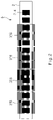
- FIG. 1 is a view illustrating a device for manufacturing a membrane-electrode gasket assembly according to the present disclosure.
- a device 10 for manufacturing a membrane-electrode gasket assembly (hereinafter, referred to as a 'manufacturing device') according to the present disclosure includes: a first sub-assembly 100 which manufactures a membrane-electrode joined body or membrane-electrode body 6 having a structure in which a membrane 2 and electrode catalysts 3 and 4 are joined to each other; a second sub-assembly 200 which is provided in a region downstream from the first sub-assembly 100 and receives the membrane-electrode joined body 6 from the first sub-assembly 100; and a third sub-assembly 300 which is provided in a region downstream from the second sub-assembly 200, and which receives the membrane-electrode joined body 6 from the second sub-assembly 200 and manufactures an assembly 7 by joining a gasket to the membrane-electrode joined body 6.
- the upstream region and the downstream region are defined with respect to a direction in which the membrane 2 is conveyed during a manufacturing process of the assembly. That is, according to the present disclosure, the membrane 2 passes, in this order, through the first sub-assembly 100, the second sub-assembly 200, and the third sub-assembly 300 during the manufacturing process of the assembly.
- the second sub-assembly 200 may be provided in a region downstream from the first sub-assembly 100
- the third sub-assembly 300 may be provided in a region downstream from the second sub-assembly 200.
- the first to third sub-assemblies 100, 200, and 300 may be provided such that the membrane 2 is disposed continuously over the first to third sub-assemblies 100, 200, and 300. That is, according to the present disclosure, a region of the membrane 2 provided in the first sub-assembly 100 and a region of the membrane 2 provided in the third sub-assembly 300 may be connected to each other by a region of the membrane 2 provided in the second sub-assembly 200.
- the first sub-assembly 100 may be configured to manufacture the membrane-electrode joined body 6, and the third sub-assembly 300 may be configured to manufacture the assembly 7 in which a gasket 5 is attached to the membrane-electrode joined body 6.
- a process of manufacturing the membrane-electrode joined body 6 and a process of manufacturing the assembly 7 may be integrally performed within a single device according to the present disclosure. Accordingly, not only may processes for manufacturing the assembly 7 be performed continuously, but also damages to the membrane-electrode joined body 6 may be minimized because a process for storing the membrane-electrode joined body 6 is not necessary prior to manufacturing the assembly 7.
- the first to third sub-assemblies will be described with reference to the drawings.
- the first sub-assembly 100 may include: a membrane unwinder 110 for supplying a film F to which the membrane 2 is attached; a first film rewinder 120 which is provided in a region downstream from the membrane unwinder 110 and collects the film F from the membrane 2; a first slot die 130 which is provided in a region downstream from the first film rewinder 120 and applies a first electrode catalyst 3 to one surface of the membrane 2; and a first adsorption roller 140 which faces the first slot die 130 and adsorbs the membrane 2.
- the first electrode catalyst 3 may be a cathode catalyst.
- the first adsorption roller 140 may adsorb the membrane 2 by creating a negative pressure therein.
- the first slot die 130 may be controlled such that the first electrode catalyst 3 is discontinuously applied to the membrane 2, and thus, first electrode catalysts 3 are spaced a certain distance from each other.
- the first sub-assembly 100 may further include a first dryer 150 that dries the membrane 2 and the first electrode catalyst 3. That is, the first dryer 150 may be configured to dry the membrane 2 and the first electrode catalyst 3 after the first electrode catalyst 3 is applied to the membrane 2. For example, the first dryer 150 may perform a drying operation in a manner of applying hot air to the membrane 2 and the first electrode catalyst 3.
- the first dryer 150 may have a first drying space S1 which is provided in a region downstream from the first adsorption roller 140 and into which the membrane 2 and the first electrode catalyst 3 flow.
- the membrane 2 and the first electrode catalyst 3 may be dried primarily while passing through the first drying space S1.
- the first sub-assembly 100 may further include: a first-first moving roller 160 provided in a region downstream from the first drying space S1 and movable along a predetermined trajectory; and a first-first controller 170 controlling movement of the first-first moving roller 160.
- the first-first moving roller 160 may move in the left-right direction along a predetermined trajectory formed in the left-right direction, and the first-first controller 170 may control the left-right directional movement of the first-first moving roller 160.
- a moving speed of the membrane 2 in the upstream region of the first-first moving roller 160 may be controlled to be different from a moving speed of the membrane 2 in the downstream region of the first-first moving roller 160.
- the first-first moving roller 160 is provided as illustrated in FIG. 1
- the first-first moving roller 160 moves in the right direction
- the length of the membrane 2 in the vicinity of the first-first moving roller 160 is increased.
- the moving speed of the membrane 2 in the downstream region of the first-first moving roller 160 becomes less than the moving speed of the membrane 2 in the upstream region of the first-first moving roller 160.
- the feed rate of the membrane 2 may be adjusted by controlling the movement of the first-first moving roller 160.
- the first sub-assembly 100 may further include: a second slot die 180 which is provided in a region downstream from the first-first moving roller 160 and applies a second electrode catalyst 4 to the other surface of the membrane 2; and a second adsorption roller 190 which faces the second slot die 180 and adsorbs the membrane 2.
- the second electrode catalyst 4 may be an anode catalyst.
- the second adsorption roller 190 may adsorb the membrane 2 by creating a negative pressure therein.
- the second slot die 180 may be controlled such that the second electrode catalyst 4 is discontinuously applied to the membrane 2, and thus, second electrode catalysts 4 are spaced a certain distance from each other.
- the first dryer 150 may have a second drying space S2 which is provided in a region downstream from the second adsorption roller 190 and into which the membrane 2, the first electrode catalyst 3, and the second electrode catalyst 4 flow.
- the membrane 2, the first electrode catalyst 3, and the second electrode catalyst 4 may be dried secondarily while passing through the second drying space S2.
- the first drying space S1 and the second drying space S2 may be spaced apart from each other in the up-down direction.
- FIG. 1 illustrates, as one example, a state in which the first drying space S1 and the second drying space S2 are formed overlapping each other when the first dryer 150 is viewed from the above.
- the first sub-assembly 100 may further include fixed rollers R which are respectively provided in a region in which the membrane 2 is separated from the film F, a region between the first adsorption roller 140 and the first drying space S1, a region between the first drying space S1 and the first-first moving roller 160, and a region between the second adsorption roller 190 and the second drying space S2. Also, the first sub-assembly 100 may further include meandering control members A which prevent the membrane 2 from meandering and are respectively provided in an upstream region of the first adsorption roller 140 and a region between the first-first moving roller 160 and the second adsorption roller 190.
- the first sub-assembly 100 may further include: a calculation member (not shown) capable of calculating the total length of the film F on the basis of the moving speed of the membrane 2; a control member (not shown) for controlling the rotation speeds and adsorption pressures of the first and second adsorption rollers 140 and 190; and a vision inspection member (not shown) for checking the application states of the first electrode catalyst 3 and the second electrode catalyst 4.
- a calculation member capable of calculating the total length of the film F on the basis of the moving speed of the membrane 2
- a control member for controlling the rotation speeds and adsorption pressures of the first and second adsorption rollers 140 and 190
- a vision inspection member (not shown) for checking the application states of the first electrode catalyst 3 and the second electrode catalyst 4.
- the second sub-assembly 200 may include: a second-first moving roller 210 movable along a predetermined trajectory; and a second-first controller 220 controlling movement of the second-first moving roller 210.
- the second-first moving roller 210 may move in the up-down direction along a predetermined trajectory formed in the up-down direction, and the second-first controller 220 may control the up-down directional movement of the second-first moving roller 210.
- a moving speed of the membrane 2 in the upstream region of the second-first moving roller 210 may be controlled to be different from a moving speed of the membrane 2 in the downstream region of the second-first moving roller 210.
- the second-first moving roller 210 when the second-first moving roller 210 moves in the upward direction, the length of the membrane 2 in the vicinity of the second-first moving roller 210 is increased.
- the moving speed of the membrane 2 in the downstream region of the second-first moving roller 210 becomes less than the moving speed of the membrane 2 in the upstream region of the second-first moving roller 210.
- the feed rate of the membrane 2 may be adjusted by controlling the movement of the second-first moving roller 210.
- a plurality of second-first moving rollers 210 may be provided along a direction in which the membrane 2 moves.
- the plurality of second-first moving rollers 210 may be provided along the left-right direction.
- FIG. 1 illustrates, as one example, a state in which two second-first moving rollers 210 are provided along the left-right direction.
- only one second-first moving roller 210 may be provided.
- the second sub-assembly 200 may further include a second dryer 230 that sprays air for drying. More specifically, the second dryer 230 may be configured to additionally dry the membrane-electrode joined body 6 supplied from the first sub-assembly 100 by spraying hot air for drying the membrane-electrode joined body 6.
- the second sub-assembly 200 may further include fixed rollers R which are respectively provided in a region between the first sub-assembly 100 and the second-first moving roller 210, a region between the plurality of second-first moving rollers 210, and a region between the second-first moving roller 210 and the third sub-assembly 300.
- the third sub-assembly 300 may include a heat-pressing part 310 which heats or presses the membrane-electrode joined body 6. More preferably, the heat-pressing part 310 may heat and press the membrane-electrode joined body 6.
- the heat-pressing part 310 may include a plurality of pressing rollers.
- the membrane-electrode joined body 6 flows into the plurality of pressing rollers provided in the heat-pressing part 310, and is then heated and pressed by the pressing rollers. Accordingly, adhesion force within the membrane-electrode joined body 6 may be improved.
- the heat-pressing part 310 may include: a third-first pressing roller 311 that faces one surface of the membrane-electrode joined body 6; and a third-second pressing roller 312 that faces the third-first pressing roller 311 with the membrane-electrode joined body 6 therebetween.
- FIG. 1 illustrates a state in which the third-second pressing roller 312 is provided above the third-first pressing roller 311.
- the third-first pressing roller 311 faces the bottom surface of the membrane-electrode joined body 6, and the third-second pressing roller 312 faces the top surface of the membrane-electrode joined body 6.
- the third-second pressing roller 312 is configured to rotate by directly receiving power, but the third-first pressing roller 311 may be configured to be freely rotatable according to the rotation of the third-second pressing roller 312 without separately receiving power.
- the heat-pressing part 310 may further include a third-third pressing roller 313 that faces the third-second pressing roller 312 with the membrane-electrode joined body 6 therebetween.
- FIG. 1 illustrates a state in which the third-third pressing roller 313 is provided above the third-second pressing roller 312. Similar to the third-second pressing roller 312, the third-third pressing roller 313 may be configured to rotate by directly receiving power.
- the heat-pressing part 310 may further include: a third-fourth pressing roller 314 that faces the third-third pressing roller 313; a third-fifth pressing roller 315 that faces the third-second pressing roller 312; and a third-sixth pressing roller 316 that faces the third-first pressing roller 311.
- FIG. 1 illustrates a state in which the third-fourth pressing roller 314 is provided on the right side of the third-third pressing roller 313, the third-fifth pressing roller 315 is provided on the right side of the third-second pressing roller 312, and the third-sixth pressing roller 316 is provided on the right side of the third-first pressing roller 311.
- the third-fourth pressing roller 314 and the third-fifth pressing roller 315 are configured to rotate by directly receiving power, but the third-sixth pressing roller 316 may be configured to be freely rotatable according to the rotation of the third-fifth pressing roller 315 without separately receiving power.
- the membrane-electrode joined body 6 may be heated and pressed while sequentially passing through a space between the third-first pressing roller 311 and the third-second pressing roller 312, a space between the third-second pressing roller 312 and the third-third pressing roller 313, a space between the third-third pressing roller 313 and the third-fourth pressing roller 314, a space between the third-fourth pressing roller 314 and the third-fifth pressing roller 315, and a space between the third-fifth pressing roller 315 and the third-sixth pressing roller 316.
- the membrane-electrode joined body 6 may be continuously heated and pressed while the plurality of pressing rollers rotate.
- the continuity between processes may be ensured.
- FIG. 2 is a view illustrating a state in which a membrane-electrode joined body is pressed by a heat-pressing part provided in a device for manufacturing a membrane-electrode gasket assembly according to another exemplary embodiment of the present disclosure.
- a heat-pressing part 310 may include a press member 318 that presses the membrane-electrode joined body 6 while moving in the up-down direction.
- a plurality of press members 318 may be provided along a direction in which the membrane-electrode joined body 6 is conveyed.
- FIG. 2 illustrates a state in which four press members 318 are provided along the direction in which the membrane-electrode joined body 6 is conveyed.
- the third sub-assembly 300 may further include: a gasket unwinder 320 supplying a film F on which a gasket 5 is attached; a third film rewinder 330 collecting the film F from the gasket 5; a gasket cutter 340 provided between the gasket unwinder 320 and the third film rewinder 330 and cutting the gasket 5; and an assembler 350 which is provided in a region downstream from the heat-pressing part 310, and which manufactures an assembly 7 by pressing and joining the membrane-electrode joined body 6 and the gasket 5 together.
- FIG. 1 illustrates a state in which the gasket unwinder 320, the third film rewinder 330, and the gasket cutter 340 are symmetrically provided on the upper and lower sides of the assembler 350.
- the assembler 350 may include: a first joining member 352 pressing the membrane-electrode joined body 6 and the gasket 5 so as to form a first joined region in the assembly 7; and a second joining member 354 pressing the membrane-electrode joined body 6 and the gasket 5 so as to form a second joined region in the assembly 7.
- the first joined region and the second joined region may represent a region in which the membrane-electrode joined body 6 and the gasket 5 are attached to each other.
- the first joined region may be different from the second joined region. Between the first joined region and the second joined region, there may be a region in which the first joined region and the second joined region overlap each other. On the other hand, there may be no region in which the first joined region and the second joined region overlap each other.
- the first joining member 352 may press a front region or a rear region of the gasket 5, and the second joining member 354 may press a left region or a right region of the gasket 5.
- the third sub-assembly 300 may further include a meandering control member A which is provided in a downstream region of the gasket unwinder 320 and prevents the gasket 5 from meandering.
- the manufacturing device 10 may further include a drying member provided on one side of the first adsorption roller 140 or the second adsorption roller 190 (for example, provided above the first adsorption roller 140 or the second adsorption roller 190).
- a drying operation may be performed by the drying member separately from the first dryer 150 right after the first electrode catalyst 3 or the second electrode catalyst 4 is applied to the membrane 2 through the first slot die 130 or the second slot die 180.
- the manufacturing device 10 may further include a moving roller provided between the heat-pressing part 310 and the assembler 350.
- the rate, at which the membrane-electrode joined body 6 discharged from the heat-pressing part 310 is supplied to the assembler 350 may be adjusted separately from the second-first moving roller 210.
- the present disclosure provide not only for ensuring continuity between processes by integrating operations performed to manufacture a membrane-electrode gasket assembly, but also for preventing the quality of the membrane-electrode gasket assembly from being deteriorated.
Landscapes
- Chemical Kinetics & Catalysis (AREA)
- Engineering & Computer Science (AREA)
- Manufacturing & Machinery (AREA)
- General Chemical & Material Sciences (AREA)
- Electrochemistry (AREA)
- Chemical & Material Sciences (AREA)
- Sustainable Development (AREA)
- Sustainable Energy (AREA)
- Life Sciences & Earth Sciences (AREA)
- Physics & Mathematics (AREA)
- Thermal Sciences (AREA)
- Fuel Cell (AREA)
- Lining Or Joining Of Plastics Or The Like (AREA)
- Hybrid Cells (AREA)
- Gasket Seals (AREA)
Abstract
Description
- This application claims the benefit of
Korean Patent Application No. 10-2021-0029677, filed on March 05, 2021 - The following description relates to a device for manufacturing a membrane-electrode gasket assembly and, more particularly, to a device for manufacturing a membrane-electrode gasket assembly for a fuel cell.
- Membrane-electrode gasket assemblies have a structure in which a positive electrode catalyst layer and a negative electrode catalyst layer are applied to the respective surfaces of a membrane. A sub-gasket is joined to each of the positive electrode catalyst layer and the negative electrode catalyst layer. Such a membrane-electrode gasket assembly is used in a fuel cell that generates electricity through an electrochemical reaction between hydrogen and oxygen.
- Meanwhile, according to the related art, in order to manufacture the membrane-electrode gasket assembly, it is required to i) manufacture a membrane-electrode joined body by applying a positive electrode catalyst layer and a negative electrode catalyst layer to the respective surfaces of a membrane and ii) join sub-gaskets to the respective surfaces of the membrane-electrode joined body.
- However, according to the related art, the operation i) and the operation ii) are performed separately, and thus, there is a limitation in that continuity between processes is interrupted. Also, according to the related art, the operation i) and the operation ii) are performed separately, and thus, the membrane-electrode joined body is wound and stored after the operation i), and then, it is required to unwind the membrane-electrode joined body again during the operation ii). Accordingly, the membrane-electrode joined body or the like is damaged between the operation i) and the operation ii), and thus, there is also a limitation in that overall quality of the membrane-electrode gasket assembly is deteriorated.
- In one general aspect, there is provided device for manufacturing a membrane-electrode gasket assembly, the device including a first sub-assembly configured to manufacture a membrane-electrode body having a membrane and an electrode catalyst being joined to each other, a second sub-assembly provided downstream from the first sub-assembly and being configured to receive the membrane-electrode body from the first sub-assembly, and a third sub-assembly provided downstream from the second sub-assembly, the third sub-assembly being configured to receive the membrane-electrode body from the second sub-assembly and to manufacture an assembly by joining a gasket to the membrane-electrode joined body, wherein the membrane is disposed continuously over the first to third sub-assembly.
- The first sub-assembly may include a membrane unwinder configured to supply a film to which the membrane is attached, a first film rewinder provided downstream from the membrane unwinder and being configured to collect the film from the membrane, a first slot die provided downstream from the first film rewinder and being configured to apply a first electrode catalyst to a surface of the membrane, and a first adsorption roller facing the first slot die and being configured to adsorb the membrane.
- The first sub-assembly may include a first dryer configured to dry the membrane and the first electrode catalyst, wherein the first dryer comprises a first drying space provided downstream from the first adsorption roller and the membrane and the first electrode catalyst flow into the first drying space.
- The first sub-assembly may include a first moving roller provided downstream from the first drying space and movable along a predetermined trajectory, and a first controller configured to control movement of the first moving roller.
- The first sub-assembly may include a second slot die provided downstream from the first moving roller and being configured to apply a second electrode catalyst to the other surface of the membrane, and a second adsorption roller facing the second slot die and being configured to adsorb the membrane.
- The first dryer may include a second drying space provided downstream from the second adsorption roller and the membrane, the first electrode catalyst, and the second electrode catalyst flow into the second drying space.
- The first moving roller may be movable in a left-right direction.
- The second sub-assembly may include a second moving roller movable along a predetermined trajectory, and a second controller configured to control movement of the second moving roller.
- A plurality of second moving rollers are provided along a direction in which the membrane moves.
- The second moving rollers may be movable in an up-down direction.
- The second sub-assembly may include a second dryer configured to spray air for drying.
- The third sub-assembly may include a heat-pressing part configured to heat or press the membrane-electrode body.
- The third sub-assembly may include a gasket unwinder configured to supply a film on which a gasket is attached, a third film rewinder configured to collect the film from the gasket, a gasket cutter provided between the gasket unwinder and the third film rewinder and configured to cut the gasket, and an assembler provided downstream from the heat-pressing part, the assembler being configured to press and join the membrane-electrode body and the gasket.
- The assembler may include a first joining member configured to press the membrane-electrode body and the gasket to form a first joined region in the membrane-electrode gasket assembly, and a second joining member configured to press the membrane-electrode body and the gasket so as to form a second joined region in the membrane-electrode gasket assembly, wherein the first joined region may be different from the second joined region.
- A direction in which the membrane-electrode gasket assembly is conveyed may be referred to as a front-rear direction, the first joining member presses a front region or a rear region of the gasket.
- The second joining member may press a left region or a right region of the gasket.
- The heat-pressing part may include a first pressing roller that may face one surface of the membrane-electrode body, a second pressing roller that may face the first pressing roller with the membrane-electrode body therebetween, and a third pressing roller that may face the second pressing roller with the membrane-electrode body therebetween.
- The second pressing roller may be disposed above the first pressing roller, and the third pressing roller may be disposed above the second pressing roller.
- The heat-pressing part further may include a fourth pressing roller that may face the third pressing roller, a fifth pressing roller that may face the second pressing roller, and a sixth pressing roller that may face the first pressing roller.
- The heat-pressing part may include a press member configured to move in an up-down direction and to press the membrane-electrode body.
- Other features and aspects will be apparent from the following detailed description, the drawings, and the claims.
- The accompanying drawings, which are included to provide a further understanding of the invention and are incorporated in and constitute a part of this specification, illustrate embodiments of the invention, and together with the description serve to explain the principles of the invention.
-
FIG. 1 is a view illustrating a device for manufacturing a membrane-electrode gasket assembly according to an exemplary embodiment of the present disclosure. -
FIG. 2 is a view illustrating a state in which a membrane-electrode joined body is pressed by a heat-pressing part provided in a device for manufacturing a membrane-electrode gasket assembly according to another exemplary embodiment of the present disclosure. - The following detailed description is provided to assist the reader in gaining a comprehensive understanding of the methods, apparatuses, and/or systems described herein. However, various changes, modifications, and equivalents of the methods, apparatuses, and/or systems described herein will be apparent after an understanding of the disclosure of this application. For example, the sequences of operations described herein are merely examples, and are not limited to those set forth herein, but may be changed as will be apparent after an understanding of the disclosure of this application, with the exception of operations necessarily occurring in a certain order. Also, descriptions of features that are known may be omitted for increased clarity and conciseness.
- The features described herein may be embodied in different forms, and are not to be construed as being limited to the examples described herein. Rather, the examples described herein have been provided merely to illustrate some of the many possible ways of implementing the methods, apparatuses, and/or systems described herein that will be apparent after an understanding of the disclosure of this application.
- The terminology used herein is for the purpose of describing particular examples only, and is not to be used to limit the disclosure. As used herein, the singular forms "a," "an," and "the" are intended to include the plural forms as well, unless the context clearly indicates otherwise. As used herein, the term "and/or" includes any one and any combination of any two or more of the associated listed items. As used herein, the terms "include," "comprise," and "have" specify the presence of stated features, numbers, operations, elements, components, and/or combinations thereof, but do not preclude the presence or addition of one or more other features, numbers, operations, elements, components, and/or combinations thereof.
- Throughout the specification, when a component is described as being "connected to" or "coupled to" another component, it may be directly "connected to" or "coupled to" the other component, or there may be one or more other components intervening therebetween. In contrast, when an element is described as being "directly connected to" or "directly coupled to" another element, there can be no other elements intervening therebetween. Likewise, similar expressions, for example, "between" and "immediately between," and "adjacent to" and "immediately adjacent to," are also to be construed in the same way. As used herein, the term "and/or" includes any one and any combination of any two or more of the associated listed items.
- Although terms such as "first," "second," and "third" may be used herein to describe various members, components, regions, layers, or sections, these members, components, regions, layers, or sections are not to be limited by these terms. Rather, these terms are only used to distinguish one member, component, region, layer, or section from another member, component, region, layer, or section. Thus, a first member, component, region, layer, or section referred to in the examples described herein may also be referred to as a second member, component, region, layer, or section without departing from the teachings of the examples.
- Hereinafter, a device for manufacturing a membrane-electrode gasket assembly according to the present disclosure will be described with reference to the drawings.
-
FIG. 1 is a view illustrating a device for manufacturing a membrane-electrode gasket assembly according to the present disclosure. - As illustrated in
FIG. 1 , adevice 10 for manufacturing a membrane-electrode gasket assembly (hereinafter, referred to as a 'manufacturing device') according to the present disclosure includes: afirst sub-assembly 100 which manufactures a membrane-electrode joined body or membrane-electrode body 6 having a structure in which amembrane 2 and electrode catalysts 3 and 4 are joined to each other; asecond sub-assembly 200 which is provided in a region downstream from thefirst sub-assembly 100 and receives the membrane-electrode joinedbody 6 from thefirst sub-assembly 100; and athird sub-assembly 300 which is provided in a region downstream from thesecond sub-assembly 200, and which receives the membrane-electrode joinedbody 6 from thesecond sub-assembly 200 and manufactures an assembly 7 by joining a gasket to the membrane-electrode joinedbody 6. Here, in the specification, the upstream region and the downstream region are defined with respect to a direction in which themembrane 2 is conveyed during a manufacturing process of the assembly. That is, according to the present disclosure, themembrane 2 passes, in this order, through thefirst sub-assembly 100, thesecond sub-assembly 200, and thethird sub-assembly 300 during the manufacturing process of the assembly. Thus, thesecond sub-assembly 200 may be provided in a region downstream from thefirst sub-assembly 100, and thethird sub-assembly 300 may be provided in a region downstream from thesecond sub-assembly 200. - Here, the according to the present disclosure, the first to
third sub-assemblies membrane 2 is disposed continuously over the first tothird sub-assemblies membrane 2 provided in thefirst sub-assembly 100 and a region of themembrane 2 provided in thethird sub-assembly 300 may be connected to each other by a region of themembrane 2 provided in thesecond sub-assembly 200. - As described above, in the
manufacturing device 10 according to the present disclosure, thefirst sub-assembly 100 may be configured to manufacture the membrane-electrode joinedbody 6, and thethird sub-assembly 300 may be configured to manufacture the assembly 7 in which a gasket 5 is attached to the membrane-electrode joinedbody 6. Thus, unlike the related art, a process of manufacturing the membrane-electrode joinedbody 6 and a process of manufacturing the assembly 7 may be integrally performed within a single device according to the present disclosure. Accordingly, not only may processes for manufacturing the assembly 7 be performed continuously, but also damages to the membrane-electrode joinedbody 6 may be minimized because a process for storing the membrane-electrode joinedbody 6 is not necessary prior to manufacturing the assembly 7. Hereinafter, the first to third sub-assemblies will be described with reference to the drawings. - The
first sub-assembly 100 may include: amembrane unwinder 110 for supplying a film F to which themembrane 2 is attached; afirst film rewinder 120 which is provided in a region downstream from themembrane unwinder 110 and collects the film F from themembrane 2; a first slot die 130 which is provided in a region downstream from thefirst film rewinder 120 and applies a first electrode catalyst 3 to one surface of themembrane 2; and afirst adsorption roller 140 which faces the first slot die 130 and adsorbs themembrane 2. For example, the first electrode catalyst 3 may be a cathode catalyst. Also, thefirst adsorption roller 140 may adsorb themembrane 2 by creating a negative pressure therein. Also, the first slot die 130 may be controlled such that the first electrode catalyst 3 is discontinuously applied to themembrane 2, and thus, first electrode catalysts 3 are spaced a certain distance from each other. - Also, the
first sub-assembly 100 may further include afirst dryer 150 that dries themembrane 2 and the first electrode catalyst 3. That is, thefirst dryer 150 may be configured to dry themembrane 2 and the first electrode catalyst 3 after the first electrode catalyst 3 is applied to themembrane 2. For example, thefirst dryer 150 may perform a drying operation in a manner of applying hot air to themembrane 2 and the first electrode catalyst 3. - Here, according to the present disclosure, the
first dryer 150 may have a first drying space S1 which is provided in a region downstream from thefirst adsorption roller 140 and into which themembrane 2 and the first electrode catalyst 3 flow. Thus, themembrane 2 and the first electrode catalyst 3 may be dried primarily while passing through the first drying space S1. - Meanwhile, the
first sub-assembly 100 may further include: a first-first movingroller 160 provided in a region downstream from the first drying space S1 and movable along a predetermined trajectory; and a first-first controller 170 controlling movement of the first-first movingroller 160. For example, the first-first movingroller 160 may move in the left-right direction along a predetermined trajectory formed in the left-right direction, and the first-first controller 170 may control the left-right directional movement of the first-first movingroller 160. - According to the present disclosure, when the first-first moving
roller 160 moves along the predetermined trajectory, a moving speed of themembrane 2 in the upstream region of the first-first movingroller 160 may be controlled to be different from a moving speed of themembrane 2 in the downstream region of the first-first movingroller 160. For example, in a case where the first-first movingroller 160 is provided as illustrated inFIG. 1 , when the first-first movingroller 160 moves in the right direction, the length of themembrane 2 in the vicinity of the first-first movingroller 160 is increased. Thus, the moving speed of themembrane 2 in the downstream region of the first-first movingroller 160 becomes less than the moving speed of themembrane 2 in the upstream region of the first-first movingroller 160. On the other hand, when the first-first movingroller 160 moves in the left direction, the length of themembrane 2 in the vicinity of the first-first movingroller 160 is reduced. Thus, the moving speed of themembrane 2 in the downstream region of the first-first movingroller 160 becomes greater than the moving speed of themembrane 2 in the upstream region of the first-first movingroller 160. Thus, according to the present disclosure, the feed rate of themembrane 2 may be adjusted by controlling the movement of the first-first movingroller 160. - Continuing to refer to
FIG. 1 , thefirst sub-assembly 100 may further include: a second slot die 180 which is provided in a region downstream from the first-first movingroller 160 and applies a second electrode catalyst 4 to the other surface of themembrane 2; and asecond adsorption roller 190 which faces the second slot die 180 and adsorbs themembrane 2. For example, the second electrode catalyst 4 may be an anode catalyst. Also, thesecond adsorption roller 190 may adsorb themembrane 2 by creating a negative pressure therein. Also, the second slot die 180 may be controlled such that the second electrode catalyst 4 is discontinuously applied to themembrane 2, and thus, second electrode catalysts 4 are spaced a certain distance from each other. - Here, as illustrated in
FIG. 1 , thefirst dryer 150 may have a second drying space S2 which is provided in a region downstream from thesecond adsorption roller 190 and into which themembrane 2, the first electrode catalyst 3, and the second electrode catalyst 4 flow. Thus, themembrane 2, the first electrode catalyst 3, and the second electrode catalyst 4 may be dried secondarily while passing through the second drying space S2. More preferably, the first drying space S1 and the second drying space S2 may be spaced apart from each other in the up-down direction.FIG. 1 illustrates, as one example, a state in which the first drying space S1 and the second drying space S2 are formed overlapping each other when thefirst dryer 150 is viewed from the above. - Meanwhile, according to the present disclosure, the
first sub-assembly 100 may further include fixed rollers R which are respectively provided in a region in which themembrane 2 is separated from the film F, a region between thefirst adsorption roller 140 and the first drying space S1, a region between the first drying space S1 and the first-first movingroller 160, and a region between thesecond adsorption roller 190 and the second drying space S2. Also, thefirst sub-assembly 100 may further include meandering control members A which prevent themembrane 2 from meandering and are respectively provided in an upstream region of thefirst adsorption roller 140 and a region between the first-first movingroller 160 and thesecond adsorption roller 190. Also, thefirst sub-assembly 100 may further include: a calculation member (not shown) capable of calculating the total length of the film F on the basis of the moving speed of themembrane 2; a control member (not shown) for controlling the rotation speeds and adsorption pressures of the first andsecond adsorption rollers - The
second sub-assembly 200 may include: a second-first movingroller 210 movable along a predetermined trajectory; and a second-first controller 220 controlling movement of the second-first movingroller 210. For example, the second-first movingroller 210 may move in the up-down direction along a predetermined trajectory formed in the up-down direction, and the second-first controller 220 may control the up-down directional movement of the second-first movingroller 210. - According to the present disclosure, when the second-first moving
roller 210 moves along the predetermined trajectory, a moving speed of themembrane 2 in the upstream region of the second-first movingroller 210 may be controlled to be different from a moving speed of themembrane 2 in the downstream region of the second-first movingroller 210. For example, in a case where the second-first movingroller 210 is provided as illustrated inFIG. 1 , when the second-first movingroller 210 moves in the upward direction, the length of themembrane 2 in the vicinity of the second-first movingroller 210 is increased. Thus, the moving speed of themembrane 2 in the downstream region of the second-first movingroller 210 becomes less than the moving speed of themembrane 2 in the upstream region of the second-first movingroller 210. On the other hand, when the second-first movingroller 210 moves in the downward direction, the length of themembrane 2 in the vicinity of the second-first movingroller 210 is reduced. Thus, the moving speed of themembrane 2 in the downstream region of the second-first movingroller 210 becomes greater than the moving speed of themembrane 2 in the upstream region of the second-first movingroller 210. Thus, according to the present disclosure, the feed rate of themembrane 2 may be adjusted by controlling the movement of the second-first movingroller 210. - Meanwhile, according to the present disclosure, a plurality of second-first moving
rollers 210 may be provided along a direction in which themembrane 2 moves. As one example, the plurality of second-first movingrollers 210 may be provided along the left-right direction.FIG. 1 illustrates, as one example, a state in which two second-first movingrollers 210 are provided along the left-right direction. However, unlike that illustrated inFIG. 1 , only one second-first movingroller 210 may be provided. - Meanwhile, the
second sub-assembly 200 may further include asecond dryer 230 that sprays air for drying. More specifically, thesecond dryer 230 may be configured to additionally dry the membrane-electrode joinedbody 6 supplied from thefirst sub-assembly 100 by spraying hot air for drying the membrane-electrode joinedbody 6. - Meanwhile, the
second sub-assembly 200 may further include fixed rollers R which are respectively provided in a region between thefirst sub-assembly 100 and the second-first movingroller 210, a region between the plurality of second-first movingrollers 210, and a region between the second-first movingroller 210 and thethird sub-assembly 300. - Continuing to refer to
FIG. 1 , thethird sub-assembly 300 may include a heat-pressingpart 310 which heats or presses the membrane-electrode joinedbody 6. More preferably, the heat-pressingpart 310 may heat and press the membrane-electrode joinedbody 6. - According to an exemplary embodiment of the present disclosure, the heat-pressing
part 310 may include a plurality of pressing rollers. Thus, according to the exemplary embodiment of the present disclosure, the membrane-electrode joinedbody 6 flows into the plurality of pressing rollers provided in the heat-pressingpart 310, and is then heated and pressed by the pressing rollers. Accordingly, adhesion force within the membrane-electrode joinedbody 6 may be improved. - More specifically, according to the exemplary embodiment of the present disclosure, the heat-pressing
part 310 may include: a third-firstpressing roller 311 that faces one surface of the membrane-electrode joinedbody 6; and a third-secondpressing roller 312 that faces the third-firstpressing roller 311 with the membrane-electrode joinedbody 6 therebetween.FIG. 1 illustrates a state in which the third-secondpressing roller 312 is provided above the third-firstpressing roller 311. The third-firstpressing roller 311 faces the bottom surface of the membrane-electrode joinedbody 6, and the third-secondpressing roller 312 faces the top surface of the membrane-electrode joinedbody 6. Here, the third-secondpressing roller 312 is configured to rotate by directly receiving power, but the third-firstpressing roller 311 may be configured to be freely rotatable according to the rotation of the third-secondpressing roller 312 without separately receiving power. - Meanwhile, according to the exemplary embodiment of the present disclosure, the heat-pressing
part 310 may further include a third-thirdpressing roller 313 that faces the third-secondpressing roller 312 with the membrane-electrode joinedbody 6 therebetween.FIG. 1 illustrates a state in which the third-thirdpressing roller 313 is provided above the third-secondpressing roller 312. Similar to the third-secondpressing roller 312, the third-thirdpressing roller 313 may be configured to rotate by directly receiving power. - Also, according to the exemplary embodiment of the present disclosure, the heat-pressing
part 310 may further include: a third-fourthpressing roller 314 that faces the third-thirdpressing roller 313; a third-fifthpressing roller 315 that faces the third-secondpressing roller 312; and a third-sixthpressing roller 316 that faces the third-firstpressing roller 311.FIG. 1 illustrates a state in which the third-fourthpressing roller 314 is provided on the right side of the third-thirdpressing roller 313, the third-fifthpressing roller 315 is provided on the right side of the third-secondpressing roller 312, and the third-sixthpressing roller 316 is provided on the right side of the third-firstpressing roller 311. Here, the third-fourthpressing roller 314 and the third-fifthpressing roller 315 are configured to rotate by directly receiving power, but the third-sixthpressing roller 316 may be configured to be freely rotatable according to the rotation of the third-fifthpressing roller 315 without separately receiving power. - That is, based on the above description, the membrane-electrode joined
body 6 may be heated and pressed while sequentially passing through a space between the third-firstpressing roller 311 and the third-secondpressing roller 312, a space between the third-secondpressing roller 312 and the third-thirdpressing roller 313, a space between the third-thirdpressing roller 313 and the third-fourthpressing roller 314, a space between the third-fourthpressing roller 314 and the third-fifthpressing roller 315, and a space between the third-fifthpressing roller 315 and the third-sixthpressing roller 316. - According to the present disclosure, when the plurality of pressing rollers are provided in the heat-pressing
part 310, the membrane-electrode joinedbody 6 may be continuously heated and pressed while the plurality of pressing rollers rotate. Thus, the continuity between processes may be ensured. -
FIG. 2 is a view illustrating a state in which a membrane-electrode joined body is pressed by a heat-pressing part provided in a device for manufacturing a membrane-electrode gasket assembly according to another exemplary embodiment of the present disclosure. - According to another exemplary embodiment of the present disclosure, unlike the exemplary embodiment of the present disclosure, a heat-pressing
part 310 may include apress member 318 that presses the membrane-electrode joinedbody 6 while moving in the up-down direction. For example, a plurality ofpress members 318 may be provided along a direction in which the membrane-electrode joinedbody 6 is conveyed.FIG. 2 illustrates a state in which fourpress members 318 are provided along the direction in which the membrane-electrode joinedbody 6 is conveyed. - Meanwhile, referring to
FIG. 1 again, thethird sub-assembly 300 according to the present disclosure may further include: agasket unwinder 320 supplying a film F on which a gasket 5 is attached; athird film rewinder 330 collecting the film F from the gasket 5; agasket cutter 340 provided between thegasket unwinder 320 and thethird film rewinder 330 and cutting the gasket 5; and anassembler 350 which is provided in a region downstream from the heat-pressingpart 310, and which manufactures an assembly 7 by pressing and joining the membrane-electrode joinedbody 6 and the gasket 5 together.FIG. 1 illustrates a state in which thegasket unwinder 320, thethird film rewinder 330, and thegasket cutter 340 are symmetrically provided on the upper and lower sides of theassembler 350. - Here, the
assembler 350 may include: a first joiningmember 352 pressing the membrane-electrode joinedbody 6 and the gasket 5 so as to form a first joined region in the assembly 7; and a second joiningmember 354 pressing the membrane-electrode joinedbody 6 and the gasket 5 so as to form a second joined region in the assembly 7. Here, the first joined region and the second joined region may represent a region in which the membrane-electrode joinedbody 6 and the gasket 5 are attached to each other. - Here, according to the present disclosure, the first joined region may be different from the second joined region. Between the first joined region and the second joined region, there may be a region in which the first joined region and the second joined region overlap each other. On the other hand, there may be no region in which the first joined region and the second joined region overlap each other.
- For example, when a direction in which the assembly 7 or the membrane-electrode joined
body 6 is conveyed is referred to as a front-rear direction, the first joiningmember 352 may press a front region or a rear region of the gasket 5, and the second joiningmember 354 may press a left region or a right region of the gasket 5. - Meanwhile, the
third sub-assembly 300 may further include a meandering control member A which is provided in a downstream region of thegasket unwinder 320 and prevents the gasket 5 from meandering. - Also, although not illustrated in the drawing, the
manufacturing device 10 according to the present disclosure may further include a drying member provided on one side of thefirst adsorption roller 140 or the second adsorption roller 190 (for example, provided above thefirst adsorption roller 140 or the second adsorption roller 190). Thus, according to the present disclosure, a drying operation may be performed by the drying member separately from thefirst dryer 150 right after the first electrode catalyst 3 or the second electrode catalyst 4 is applied to themembrane 2 through the first slot die 130 or the second slot die 180. - Also, although not illustrated in the drawing, the
manufacturing device 10 according to the present disclosure may further include a moving roller provided between the heat-pressingpart 310 and theassembler 350. Thus, according to the present disclosure, the rate, at which the membrane-electrode joinedbody 6 discharged from the heat-pressingpart 310 is supplied to theassembler 350, may be adjusted separately from the second-first movingroller 210. - According to the present disclosure, it is possible not only to ensure the continuity between the processes by integrating the operations performed to manufacture the membrane-electrode gasket assembly, but also to prevent the quality of the membrane-electrode gasket assembly from being deteriorated.
- The present disclosure provide not only for ensuring continuity between processes by integrating operations performed to manufacture a membrane-electrode gasket assembly, but also for preventing the quality of the membrane-electrode gasket assembly from being deteriorated.
- While this disclosure includes specific examples, it will be apparent after an understanding of the disclosure of this application that various changes in form and details may be made in these examples without departing from the spirit and scope of the claims and their equivalents. The examples described herein are to be considered in a descriptive sense only, and not for purposes of limitation. Descriptions of features or aspects in each example are to be considered as being applicable to similar features or aspects in other examples. Suitable results may be achieved if the described techniques are performed in a different order, and/or if components in a described system, architecture, device, or circuit are combined in a different manner, and/or replaced or supplemented by other components or their equivalents.
- Therefore, the scope of the disclosure is defined not by the detailed description, but by the claims and their equivalents, and all variations within the scope of the claims and their equivalents are to be construed as being included in the disclosure.
Claims (15)
- A device for manufacturing a membrane-electrode gasket assembly, the device comprising:a first sub-assembly configured to manufacture a membrane-electrode body having a membrane and an electrode catalyst being joined to each other;a second sub-assembly provided downstream from the first sub-assembly and being configured to receive the membrane-electrode body from the first sub-assembly; anda third sub-assembly provided downstream from the second sub-assembly, the third sub-assembly being configured to receive the membrane-electrode body from the second sub-assembly and to manufacture an assembly by joining a gasket to the membrane-electrode joined body,wherein the membrane is disposed continuously over the first to third sub-assembly.
- The device of claim 1, wherein the first sub-assembly comprises:a membrane unwinder configured to supply a film to which the membrane is attached;a first film rewinder provided downstream from the membrane unwinder and being configured to collect the film from the membrane;a first slot die provided downstream from the first film rewinder and being configured to apply a first electrode catalyst to a surface of the membrane; anda first adsorption roller facing the first slot die and being configured to adsorb the membrane.
- The device of claim 2, wherein the first sub-assembly further comprises a first dryer configured to dry the membrane and the first electrode catalyst,
wherein the first dryer comprises a first drying space provided downstream from the first adsorption roller and the membrane and the first electrode catalyst flow into the first drying space. - The device of claim 3, wherein the first sub-assembly further comprises:a first moving roller provided downstream from the first drying space and movable along a predetermined trajectory; anda first controller configured to control movement of the first moving roller.
- The device of claim 4, wherein the first sub-assembly further comprises:a second slot die provided downstream from the first moving roller and being configured to apply a second electrode catalyst to the other surface of the membrane; anda second adsorption roller facing the second slot die and being configured to adsorb the membrane.
- The device of claim 5, wherein the first dryer comprises a second drying space provided downstream from the second adsorption roller and the membrane, the first electrode catalyst, and the second electrode catalyst flow into the second drying space.
- The device of claim 4, wherein the first moving roller is movable in a left-right direction.
- The device of claim 1, wherein the second sub-assembly comprises:a second moving roller movable along a predetermined trajectory; anda second controller configured to control movement of the second moving roller.
- The device of claim 8, wherein a plurality of second moving rollers are provided along a direction in which the membrane moves.
- The device of claim 9, wherein the second moving rollers are movable in an up-down direction.
- The device of claim 8, wherein the second sub-assembly further comprises a second dryer configured to spray air for drying.
- The device of claim 1, wherein the third sub-assembly comprises a heat-pressing part configured to heat or press the membrane-electrode body.
- The device of claim 12, wherein the third sub-assembly comprises:a gasket unwinder configured to supply a film on which a gasket is attached;a third film rewinder configured to collect the film from the gasket;a gasket cutter provided between the gasket unwinder and the third film rewinder and configured to cut the gasket; andan assembler provided downstream from the heat-pressing part, the assembler being configured to press and join the membrane-electrode body and the gasket.
- The device of claim 13, wherein the assembler comprises:a first joining member configured to press the membrane-electrode body and the gasket to form a first joined region in the membrane-electrode gasket assembly; anda second joining member configured to press the membrane-electrode body and the gasket so as to form a second joined region in the membrane-electrode gasket assembly,wherein the first joined region is different from the second joined region.
- The device of claim 14, wherein a direction in which the membrane-electrode gasket assembly is conveyed is referred to as a front-rear direction,
the first joining member presses a front region or a rear region of the gasket.
Applications Claiming Priority (1)
| Application Number | Priority Date | Filing Date | Title |
|---|---|---|---|
| KR1020210029677A KR20220125769A (en) | 2021-03-05 | 2021-03-05 | Device for manufacturing membrane-electrode gasket assembly |
Publications (2)
| Publication Number | Publication Date |
|---|---|
| EP4053930A1 true EP4053930A1 (en) | 2022-09-07 |
| EP4053930B1 EP4053930B1 (en) | 2024-02-28 |
Family
ID=77750165
Family Applications (1)
| Application Number | Title | Priority Date | Filing Date |
|---|---|---|---|
| EP21196608.0A Active EP4053930B1 (en) | 2021-03-05 | 2021-09-14 | Device for manufacturing membrane-electrode gasket assembly |
Country Status (5)
| Country | Link |
|---|---|
| US (1) | US12506162B2 (en) |
| EP (1) | EP4053930B1 (en) |
| JP (1) | JP7785500B2 (en) |
| KR (1) | KR20220125769A (en) |
| CN (1) | CN115020715A (en) |
Citations (2)
| Publication number | Priority date | Publication date | Assignee | Title |
|---|---|---|---|---|
| GB2555127A (en) * | 2016-10-19 | 2018-04-25 | Univ Cape Town | A method of coating a membrane with a catalyst |
| KR102038886B1 (en) * | 2017-12-22 | 2019-10-31 | (주)프로템 | Apparatus for Fabricating the Membrane-Electrode Assembly of Fuel Cell |
Family Cites Families (9)
| Publication number | Priority date | Publication date | Assignee | Title |
|---|---|---|---|---|
| US8288059B2 (en) | 2006-12-15 | 2012-10-16 | 3M Innovative Properties Company | Processing methods and systems for assembling fuel cell perimeter gaskets |
| KR101072829B1 (en) | 2007-01-30 | 2011-10-14 | 주식회사 엘지화학 | Method and system of preparing Membrane-electrode assembly of fuel cell |
| JP2008311012A (en) * | 2007-06-13 | 2008-12-25 | Toyota Motor Corp | Production apparatus and production method for electrode material assembly for fuel cell, fuel cell |
| KR101092221B1 (en) | 2009-04-23 | 2011-12-12 | 주식회사 테크랜드 | A Manufacturing method for Membrane Electrode Assembly for fuel cell and A manufacturing apparutus thereof |
| DE102009018914A1 (en) * | 2009-04-28 | 2010-11-18 | Otto Junker Gmbh | Device for compensation of tension fluctuations and / or for adjusting the tension on a conveyed flexible strand of material |
| KR101294825B1 (en) * | 2010-05-20 | 2013-08-08 | 주식회사 제이앤티지 | Method for preparing carbon substrate for gas diffusion layer of polymer electrolyte membrane fuel cell, carbon substrate prepared thereby, and system for manufacturing the same |
| KR101703618B1 (en) * | 2015-09-09 | 2017-02-07 | 현대자동차 주식회사 | Membrane electrode assembly manufacturing device |
| KR101905560B1 (en) * | 2016-03-08 | 2018-11-21 | 현대자동차 주식회사 | Device and method for manufacturing membrane-electrode assembly of fuel cell |
| KR102371231B1 (en) * | 2017-05-18 | 2022-03-04 | 현대자동차 주식회사 | Device and method for manufacturing membrane-electrode assembly of fuel cell |
-
2021
- 2021-03-05 KR KR1020210029677A patent/KR20220125769A/en not_active Ceased
- 2021-09-01 US US17/463,672 patent/US12506162B2/en active Active
- 2021-09-14 EP EP21196608.0A patent/EP4053930B1/en active Active
- 2021-09-30 CN CN202111163310.1A patent/CN115020715A/en active Pending
- 2021-10-13 JP JP2021167858A patent/JP7785500B2/en active Active
Patent Citations (2)
| Publication number | Priority date | Publication date | Assignee | Title |
|---|---|---|---|---|
| GB2555127A (en) * | 2016-10-19 | 2018-04-25 | Univ Cape Town | A method of coating a membrane with a catalyst |
| KR102038886B1 (en) * | 2017-12-22 | 2019-10-31 | (주)프로템 | Apparatus for Fabricating the Membrane-Electrode Assembly of Fuel Cell |
Also Published As
| Publication number | Publication date |
|---|---|
| KR20220125769A (en) | 2022-09-14 |
| JP7785500B2 (en) | 2025-12-15 |
| EP4053930B1 (en) | 2024-02-28 |
| US20220285700A1 (en) | 2022-09-08 |
| JP2022135896A (en) | 2022-09-15 |
| US12506162B2 (en) | 2025-12-23 |
| CN115020715A (en) | 2022-09-06 |
Similar Documents
| Publication | Publication Date | Title |
|---|---|---|
| CN107851818B (en) | Method and apparatus for manufacturing membrane electrode assemblies for fuel cells | |
| US20100167176A1 (en) | Manufacturing apparatus and method for fuel cell electrode material assembly, and fuel cell | |
| US10084195B2 (en) | Method for the production of a water transfer compound | |
| KR101857854B1 (en) | Manufacturing method for reinforced electrolyte membrane and manufacturing apparatus of manufacturing the same | |
| KR102129217B1 (en) | Coating device and film recovery method | |
| KR20150120790A (en) | Device and method for manufacturing membrane-electrode assembly of fuel cell | |
| US20240387860A1 (en) | Method and device for producing an electrode-separator assembly for a battery cell | |
| KR20180111711A (en) | Apparatus for pressing electrode of secondary battery | |
| US12506162B2 (en) | Device for manufacturing membrane-electrode gasket assembly | |
| JP2012009281A (en) | Battery production method and device production method | |
| JP6231259B2 (en) | Method of manufacturing membrane electrode assembly for fuel cell | |
| KR20190009803A (en) | Coating device and coating method | |
| JP5954233B2 (en) | Method and apparatus for manufacturing transfer roller and membrane electrode assembly | |
| US20240383712A1 (en) | Electrode Manufacturing Apparatus | |
| JP6926855B2 (en) | Coating equipment | |
| JP2014107108A (en) | Electrode coating device | |
| JP5979100B2 (en) | Manufacturing method of membrane electrode assembly and electrolyte membrane winding roller | |
| CN113540473A (en) | Apparatus and method for making membrane-electrode assemblies for fuel cells | |
| JP2010120293A (en) | Method for continuously joining membrane-protective layer | |
| JP2014203802A (en) | Joining device and joining method | |
| JP2015032416A (en) | Film transfer apparatus and film transfer method | |
| JP5884704B2 (en) | Manufacturing method and manufacturing apparatus for membrane electrode assembly for fuel cell | |
| US12457694B2 (en) | Multilayer circuit board manufacturing apparatus and multilayer circuit board manufacturing method | |
| JP2020027792A (en) | Apparatus for manufacturing fuel cell assembly | |
| JP2016157577A (en) | Manufacturing apparatus for electrode housing separator |
Legal Events
| Date | Code | Title | Description |
|---|---|---|---|
| PUAI | Public reference made under article 153(3) epc to a published international application that has entered the european phase |
Free format text: ORIGINAL CODE: 0009012 |
|
| STAA | Information on the status of an ep patent application or granted ep patent |
Free format text: STATUS: REQUEST FOR EXAMINATION WAS MADE |
|
| 17P | Request for examination filed |
Effective date: 20210914 |
|
| AK | Designated contracting states |
Kind code of ref document: A1 Designated state(s): AL AT BE BG CH CY CZ DE DK EE ES FI FR GB GR HR HU IE IS IT LI LT LU LV MC MK MT NL NO PL PT RO RS SE SI SK SM TR |
|
| RBV | Designated contracting states (corrected) |
Designated state(s): AL AT BE BG CH CY CZ DE DK EE ES FI FR GB GR HR HU IE IS IT LI LT LU LV MC MK MT NL NO PL PT RO RS SE SI SK SM TR |
|
| RIC1 | Information provided on ipc code assigned before grant |
Ipc: H01M 8/10 20160101ALN20230629BHEP Ipc: H01M 8/1004 20160101ALN20230629BHEP Ipc: B05C 5/02 20060101ALN20230629BHEP Ipc: B32B 37/20 20060101ALI20230629BHEP Ipc: H01M 8/0286 20160101ALI20230629BHEP Ipc: H01M 8/0273 20160101ALI20230629BHEP Ipc: H01M 8/0271 20160101ALI20230629BHEP Ipc: H01M 4/88 20060101ALI20230629BHEP Ipc: B32B 38/10 20060101ALI20230629BHEP Ipc: B32B 38/00 20060101ALI20230629BHEP Ipc: H01M 4/04 20060101AFI20230629BHEP |
|
| RIC1 | Information provided on ipc code assigned before grant |
Ipc: H01M 8/10 20160101ALN20230717BHEP Ipc: H01M 8/1004 20160101ALN20230717BHEP Ipc: B05C 5/02 20060101ALN20230717BHEP Ipc: B32B 37/20 20060101ALI20230717BHEP Ipc: H01M 8/0286 20160101ALI20230717BHEP Ipc: H01M 8/0273 20160101ALI20230717BHEP Ipc: H01M 8/0271 20160101ALI20230717BHEP Ipc: H01M 4/88 20060101ALI20230717BHEP Ipc: B32B 38/10 20060101ALI20230717BHEP Ipc: B32B 38/00 20060101ALI20230717BHEP Ipc: H01M 4/04 20060101AFI20230717BHEP |
|
| RIC1 | Information provided on ipc code assigned before grant |
Ipc: H01M 8/10 20160101ALN20230802BHEP Ipc: H01M 8/1004 20160101ALN20230802BHEP Ipc: B05C 5/02 20060101ALN20230802BHEP Ipc: B32B 37/20 20060101ALI20230802BHEP Ipc: H01M 8/0286 20160101ALI20230802BHEP Ipc: H01M 8/0273 20160101ALI20230802BHEP Ipc: H01M 8/0271 20160101ALI20230802BHEP Ipc: H01M 4/88 20060101ALI20230802BHEP Ipc: B32B 38/10 20060101ALI20230802BHEP Ipc: B32B 38/00 20060101ALI20230802BHEP Ipc: H01M 4/04 20060101AFI20230802BHEP |
|
| GRAP | Despatch of communication of intention to grant a patent |
Free format text: ORIGINAL CODE: EPIDOSNIGR1 |
|
| STAA | Information on the status of an ep patent application or granted ep patent |
Free format text: STATUS: GRANT OF PATENT IS INTENDED |
|
| INTG | Intention to grant announced |
Effective date: 20230922 |
|
| RIC1 | Information provided on ipc code assigned before grant |
Ipc: H01M 8/10 20160101ALN20230911BHEP Ipc: H01M 8/1004 20160101ALN20230911BHEP Ipc: B05C 5/02 20060101ALN20230911BHEP Ipc: B32B 37/20 20060101ALI20230911BHEP Ipc: H01M 8/0286 20160101ALI20230911BHEP Ipc: H01M 8/0273 20160101ALI20230911BHEP Ipc: H01M 8/0271 20160101ALI20230911BHEP Ipc: H01M 4/88 20060101ALI20230911BHEP Ipc: B32B 38/10 20060101ALI20230911BHEP Ipc: B32B 38/00 20060101ALI20230911BHEP Ipc: H01M 4/04 20060101AFI20230911BHEP |
|
| GRAS | Grant fee paid |
Free format text: ORIGINAL CODE: EPIDOSNIGR3 |
|
| GRAA | (expected) grant |
Free format text: ORIGINAL CODE: 0009210 |
|
| STAA | Information on the status of an ep patent application or granted ep patent |
Free format text: STATUS: THE PATENT HAS BEEN GRANTED |
|
| AK | Designated contracting states |
Kind code of ref document: B1 Designated state(s): AL AT BE BG CH CY CZ DE DK EE ES FI FR GB GR HR HU IE IS IT LI LT LU LV MC MK MT NL NO PL PT RO RS SE SI SK SM TR |
|
| P01 | Opt-out of the competence of the unified patent court (upc) registered |
Effective date: 20240118 |
|
| REG | Reference to a national code |
Ref country code: GB Ref legal event code: FG4D |
|
| REG | Reference to a national code |
Ref country code: CH Ref legal event code: EP |
|
| REG | Reference to a national code |
Ref country code: DE Ref legal event code: R096 Ref document number: 602021009790 Country of ref document: DE |
|
| REG | Reference to a national code |
Ref country code: IE Ref legal event code: FG4D |
|
| REG | Reference to a national code |
Ref country code: LT Ref legal event code: MG9D |
|
| PG25 | Lapsed in a contracting state [announced via postgrant information from national office to epo] |
Ref country code: IS Free format text: LAPSE BECAUSE OF FAILURE TO SUBMIT A TRANSLATION OF THE DESCRIPTION OR TO PAY THE FEE WITHIN THE PRESCRIBED TIME-LIMIT Effective date: 20240628 |
|
| REG | Reference to a national code |
Ref country code: NL Ref legal event code: MP Effective date: 20240228 |
|
| PG25 | Lapsed in a contracting state [announced via postgrant information from national office to epo] |
Ref country code: LT Free format text: LAPSE BECAUSE OF FAILURE TO SUBMIT A TRANSLATION OF THE DESCRIPTION OR TO PAY THE FEE WITHIN THE PRESCRIBED TIME-LIMIT Effective date: 20240228 |
|
| PG25 | Lapsed in a contracting state [announced via postgrant information from national office to epo] |
Ref country code: GR Free format text: LAPSE BECAUSE OF FAILURE TO SUBMIT A TRANSLATION OF THE DESCRIPTION OR TO PAY THE FEE WITHIN THE PRESCRIBED TIME-LIMIT Effective date: 20240529 |
|
| PG25 | Lapsed in a contracting state [announced via postgrant information from national office to epo] |
Ref country code: HR Free format text: LAPSE BECAUSE OF FAILURE TO SUBMIT A TRANSLATION OF THE DESCRIPTION OR TO PAY THE FEE WITHIN THE PRESCRIBED TIME-LIMIT Effective date: 20240228 Ref country code: RS Free format text: LAPSE BECAUSE OF FAILURE TO SUBMIT A TRANSLATION OF THE DESCRIPTION OR TO PAY THE FEE WITHIN THE PRESCRIBED TIME-LIMIT Effective date: 20240528 Ref country code: NL Free format text: LAPSE BECAUSE OF FAILURE TO SUBMIT A TRANSLATION OF THE DESCRIPTION OR TO PAY THE FEE WITHIN THE PRESCRIBED TIME-LIMIT Effective date: 20240228 |
|
| PG25 | Lapsed in a contracting state [announced via postgrant information from national office to epo] |
Ref country code: ES Free format text: LAPSE BECAUSE OF FAILURE TO SUBMIT A TRANSLATION OF THE DESCRIPTION OR TO PAY THE FEE WITHIN THE PRESCRIBED TIME-LIMIT Effective date: 20240228 |
|
| PG25 | Lapsed in a contracting state [announced via postgrant information from national office to epo] |
Ref country code: RS Free format text: LAPSE BECAUSE OF FAILURE TO SUBMIT A TRANSLATION OF THE DESCRIPTION OR TO PAY THE FEE WITHIN THE PRESCRIBED TIME-LIMIT Effective date: 20240528 Ref country code: NO Free format text: LAPSE BECAUSE OF FAILURE TO SUBMIT A TRANSLATION OF THE DESCRIPTION OR TO PAY THE FEE WITHIN THE PRESCRIBED TIME-LIMIT Effective date: 20240528 Ref country code: NL Free format text: LAPSE BECAUSE OF FAILURE TO SUBMIT A TRANSLATION OF THE DESCRIPTION OR TO PAY THE FEE WITHIN THE PRESCRIBED TIME-LIMIT Effective date: 20240228 Ref country code: LT Free format text: LAPSE BECAUSE OF FAILURE TO SUBMIT A TRANSLATION OF THE DESCRIPTION OR TO PAY THE FEE WITHIN THE PRESCRIBED TIME-LIMIT Effective date: 20240228 Ref country code: IS Free format text: LAPSE BECAUSE OF FAILURE TO SUBMIT A TRANSLATION OF THE DESCRIPTION OR TO PAY THE FEE WITHIN THE PRESCRIBED TIME-LIMIT Effective date: 20240628 Ref country code: HR Free format text: LAPSE BECAUSE OF FAILURE TO SUBMIT A TRANSLATION OF THE DESCRIPTION OR TO PAY THE FEE WITHIN THE PRESCRIBED TIME-LIMIT Effective date: 20240228 Ref country code: GR Free format text: LAPSE BECAUSE OF FAILURE TO SUBMIT A TRANSLATION OF THE DESCRIPTION OR TO PAY THE FEE WITHIN THE PRESCRIBED TIME-LIMIT Effective date: 20240529 Ref country code: FI Free format text: LAPSE BECAUSE OF FAILURE TO SUBMIT A TRANSLATION OF THE DESCRIPTION OR TO PAY THE FEE WITHIN THE PRESCRIBED TIME-LIMIT Effective date: 20240228 Ref country code: ES Free format text: LAPSE BECAUSE OF FAILURE TO SUBMIT A TRANSLATION OF THE DESCRIPTION OR TO PAY THE FEE WITHIN THE PRESCRIBED TIME-LIMIT Effective date: 20240228 Ref country code: BG Free format text: LAPSE BECAUSE OF FAILURE TO SUBMIT A TRANSLATION OF THE DESCRIPTION OR TO PAY THE FEE WITHIN THE PRESCRIBED TIME-LIMIT Effective date: 20240228 |
|
| PG25 | Lapsed in a contracting state [announced via postgrant information from national office to epo] |
Ref country code: PL Free format text: LAPSE BECAUSE OF FAILURE TO SUBMIT A TRANSLATION OF THE DESCRIPTION OR TO PAY THE FEE WITHIN THE PRESCRIBED TIME-LIMIT Effective date: 20240228 Ref country code: PT Free format text: LAPSE BECAUSE OF FAILURE TO SUBMIT A TRANSLATION OF THE DESCRIPTION OR TO PAY THE FEE WITHIN THE PRESCRIBED TIME-LIMIT Effective date: 20240628 |
|
| REG | Reference to a national code |
Ref country code: AT Ref legal event code: MK05 Ref document number: 1662069 Country of ref document: AT Kind code of ref document: T Effective date: 20240228 |
|
| PG25 | Lapsed in a contracting state [announced via postgrant information from national office to epo] |
Ref country code: SE Free format text: LAPSE BECAUSE OF FAILURE TO SUBMIT A TRANSLATION OF THE DESCRIPTION OR TO PAY THE FEE WITHIN THE PRESCRIBED TIME-LIMIT Effective date: 20240228 Ref country code: PT Free format text: LAPSE BECAUSE OF FAILURE TO SUBMIT A TRANSLATION OF THE DESCRIPTION OR TO PAY THE FEE WITHIN THE PRESCRIBED TIME-LIMIT Effective date: 20240628 Ref country code: PL Free format text: LAPSE BECAUSE OF FAILURE TO SUBMIT A TRANSLATION OF THE DESCRIPTION OR TO PAY THE FEE WITHIN THE PRESCRIBED TIME-LIMIT Effective date: 20240228 Ref country code: LV Free format text: LAPSE BECAUSE OF FAILURE TO SUBMIT A TRANSLATION OF THE DESCRIPTION OR TO PAY THE FEE WITHIN THE PRESCRIBED TIME-LIMIT Effective date: 20240228 |
|
| PG25 | Lapsed in a contracting state [announced via postgrant information from national office to epo] |
Ref country code: DK Free format text: LAPSE BECAUSE OF FAILURE TO SUBMIT A TRANSLATION OF THE DESCRIPTION OR TO PAY THE FEE WITHIN THE PRESCRIBED TIME-LIMIT Effective date: 20240228 |
|
| PG25 | Lapsed in a contracting state [announced via postgrant information from national office to epo] |
Ref country code: SM Free format text: LAPSE BECAUSE OF FAILURE TO SUBMIT A TRANSLATION OF THE DESCRIPTION OR TO PAY THE FEE WITHIN THE PRESCRIBED TIME-LIMIT Effective date: 20240228 |
|
| PG25 | Lapsed in a contracting state [announced via postgrant information from national office to epo] |
Ref country code: CZ Free format text: LAPSE BECAUSE OF FAILURE TO SUBMIT A TRANSLATION OF THE DESCRIPTION OR TO PAY THE FEE WITHIN THE PRESCRIBED TIME-LIMIT Effective date: 20240228 Ref country code: EE Free format text: LAPSE BECAUSE OF FAILURE TO SUBMIT A TRANSLATION OF THE DESCRIPTION OR TO PAY THE FEE WITHIN THE PRESCRIBED TIME-LIMIT Effective date: 20240228 |
|
| PG25 | Lapsed in a contracting state [announced via postgrant information from national office to epo] |
Ref country code: AT Free format text: LAPSE BECAUSE OF FAILURE TO SUBMIT A TRANSLATION OF THE DESCRIPTION OR TO PAY THE FEE WITHIN THE PRESCRIBED TIME-LIMIT Effective date: 20240228 |
|
| PG25 | Lapsed in a contracting state [announced via postgrant information from national office to epo] |
Ref country code: SK Free format text: LAPSE BECAUSE OF FAILURE TO SUBMIT A TRANSLATION OF THE DESCRIPTION OR TO PAY THE FEE WITHIN THE PRESCRIBED TIME-LIMIT Effective date: 20240228 |
|
| PG25 | Lapsed in a contracting state [announced via postgrant information from national office to epo] |
Ref country code: SM Free format text: LAPSE BECAUSE OF FAILURE TO SUBMIT A TRANSLATION OF THE DESCRIPTION OR TO PAY THE FEE WITHIN THE PRESCRIBED TIME-LIMIT Effective date: 20240228 Ref country code: SK Free format text: LAPSE BECAUSE OF FAILURE TO SUBMIT A TRANSLATION OF THE DESCRIPTION OR TO PAY THE FEE WITHIN THE PRESCRIBED TIME-LIMIT Effective date: 20240228 Ref country code: RO Free format text: LAPSE BECAUSE OF FAILURE TO SUBMIT A TRANSLATION OF THE DESCRIPTION OR TO PAY THE FEE WITHIN THE PRESCRIBED TIME-LIMIT Effective date: 20240228 Ref country code: EE Free format text: LAPSE BECAUSE OF FAILURE TO SUBMIT A TRANSLATION OF THE DESCRIPTION OR TO PAY THE FEE WITHIN THE PRESCRIBED TIME-LIMIT Effective date: 20240228 Ref country code: DK Free format text: LAPSE BECAUSE OF FAILURE TO SUBMIT A TRANSLATION OF THE DESCRIPTION OR TO PAY THE FEE WITHIN THE PRESCRIBED TIME-LIMIT Effective date: 20240228 Ref country code: CZ Free format text: LAPSE BECAUSE OF FAILURE TO SUBMIT A TRANSLATION OF THE DESCRIPTION OR TO PAY THE FEE WITHIN THE PRESCRIBED TIME-LIMIT Effective date: 20240228 Ref country code: AT Free format text: LAPSE BECAUSE OF FAILURE TO SUBMIT A TRANSLATION OF THE DESCRIPTION OR TO PAY THE FEE WITHIN THE PRESCRIBED TIME-LIMIT Effective date: 20240228 |
|
| REG | Reference to a national code |
Ref country code: DE Ref legal event code: R081 Ref document number: 602021009790 Country of ref document: DE Owner name: KIA CORPORATION, KR Free format text: FORMER OWNER: HYUNDAI MOBIS CO., LTD., SEOUL, KR Ref country code: DE Ref legal event code: R081 Ref document number: 602021009790 Country of ref document: DE Owner name: HYUNDAI MOTOR COMPANY, KR Free format text: FORMER OWNER: HYUNDAI MOBIS CO., LTD., SEOUL, KR |
|
| REG | Reference to a national code |
Ref country code: DE Ref legal event code: R097 Ref document number: 602021009790 Country of ref document: DE |
|
| PG25 | Lapsed in a contracting state [announced via postgrant information from national office to epo] |
Ref country code: IT Free format text: LAPSE BECAUSE OF FAILURE TO SUBMIT A TRANSLATION OF THE DESCRIPTION OR TO PAY THE FEE WITHIN THE PRESCRIBED TIME-LIMIT Effective date: 20240228 |
|
| REG | Reference to a national code |
Ref country code: GB Ref legal event code: 732E Free format text: REGISTERED BETWEEN 20241107 AND 20241113 |
|
| PG25 | Lapsed in a contracting state [announced via postgrant information from national office to epo] |
Ref country code: IT Free format text: LAPSE BECAUSE OF FAILURE TO SUBMIT A TRANSLATION OF THE DESCRIPTION OR TO PAY THE FEE WITHIN THE PRESCRIBED TIME-LIMIT Effective date: 20240228 |
|
| PLBE | No opposition filed within time limit |
Free format text: ORIGINAL CODE: 0009261 |
|
| STAA | Information on the status of an ep patent application or granted ep patent |
Free format text: STATUS: NO OPPOSITION FILED WITHIN TIME LIMIT |
|
| 26N | No opposition filed |
Effective date: 20241129 |
|
| PG25 | Lapsed in a contracting state [announced via postgrant information from national office to epo] |
Ref country code: SI Free format text: LAPSE BECAUSE OF FAILURE TO SUBMIT A TRANSLATION OF THE DESCRIPTION OR TO PAY THE FEE WITHIN THE PRESCRIBED TIME-LIMIT Effective date: 20240228 Ref country code: MC Free format text: LAPSE BECAUSE OF FAILURE TO SUBMIT A TRANSLATION OF THE DESCRIPTION OR TO PAY THE FEE WITHIN THE PRESCRIBED TIME-LIMIT Effective date: 20240228 |
|
| REG | Reference to a national code |
Ref country code: CH Ref legal event code: PL |
|
| PG25 | Lapsed in a contracting state [announced via postgrant information from national office to epo] |
Ref country code: LU Free format text: LAPSE BECAUSE OF NON-PAYMENT OF DUE FEES Effective date: 20240914 |
|
| REG | Reference to a national code |
Ref country code: BE Ref legal event code: MM Effective date: 20240930 |
|
| PG25 | Lapsed in a contracting state [announced via postgrant information from national office to epo] |
Ref country code: BE Free format text: LAPSE BECAUSE OF NON-PAYMENT OF DUE FEES Effective date: 20240930 |
|
| PG25 | Lapsed in a contracting state [announced via postgrant information from national office to epo] |
Ref country code: CH Free format text: LAPSE BECAUSE OF NON-PAYMENT OF DUE FEES Effective date: 20240930 |
|
| PG25 | Lapsed in a contracting state [announced via postgrant information from national office to epo] |
Ref country code: IE Free format text: LAPSE BECAUSE OF NON-PAYMENT OF DUE FEES Effective date: 20240914 |
|
| PGFP | Annual fee paid to national office [announced via postgrant information from national office to epo] |
Ref country code: DE Payment date: 20250820 Year of fee payment: 5 |
|
| PGFP | Annual fee paid to national office [announced via postgrant information from national office to epo] |
Ref country code: GB Payment date: 20250820 Year of fee payment: 5 |
|
| PGFP | Annual fee paid to national office [announced via postgrant information from national office to epo] |
Ref country code: FR Payment date: 20250821 Year of fee payment: 5 |
|
| PG25 | Lapsed in a contracting state [announced via postgrant information from national office to epo] |
Ref country code: CY Free format text: LAPSE BECAUSE OF FAILURE TO SUBMIT A TRANSLATION OF THE DESCRIPTION OR TO PAY THE FEE WITHIN THE PRESCRIBED TIME-LIMIT; INVALID AB INITIO Effective date: 20210914 |
|
| PG25 | Lapsed in a contracting state [announced via postgrant information from national office to epo] |
Ref country code: HU Free format text: LAPSE BECAUSE OF FAILURE TO SUBMIT A TRANSLATION OF THE DESCRIPTION OR TO PAY THE FEE WITHIN THE PRESCRIBED TIME-LIMIT; INVALID AB INITIO Effective date: 20210914 |