EP4053822A1 - Ship docking assistance device - Google Patents
Ship docking assistance device Download PDFInfo
- Publication number
- EP4053822A1 EP4053822A1 EP20881714.8A EP20881714A EP4053822A1 EP 4053822 A1 EP4053822 A1 EP 4053822A1 EP 20881714 A EP20881714 A EP 20881714A EP 4053822 A1 EP4053822 A1 EP 4053822A1
- Authority
- EP
- European Patent Office
- Prior art keywords
- ship
- azimuth
- acquisition unit
- point
- map
- Prior art date
- Legal status (The legal status is an assumption and is not a legal conclusion. Google has not performed a legal analysis and makes no representation as to the accuracy of the status listed.)
- Pending
Links
Images



Classifications
-
- G—PHYSICS
- G05—CONTROLLING; REGULATING
- G05D—SYSTEMS FOR CONTROLLING OR REGULATING NON-ELECTRIC VARIABLES
- G05D1/00—Control of position, course, altitude or attitude of land, water, air or space vehicles, e.g. using automatic pilots
- G05D1/60—Intended control result
- G05D1/656—Interaction with payloads or external entities
- G05D1/661—Docking at a base station
-
- B—PERFORMING OPERATIONS; TRANSPORTING
- B63—SHIPS OR OTHER WATERBORNE VESSELS; RELATED EQUIPMENT
- B63B—SHIPS OR OTHER WATERBORNE VESSELS; EQUIPMENT FOR SHIPPING
- B63B79/00—Monitoring properties or operating parameters of vessels in operation
- B63B79/10—Monitoring properties or operating parameters of vessels in operation using sensors, e.g. pressure sensors, strain gauges or accelerometers
- B63B79/15—Monitoring properties or operating parameters of vessels in operation using sensors, e.g. pressure sensors, strain gauges or accelerometers for monitoring environmental variables, e.g. wave height or weather data
-
- B—PERFORMING OPERATIONS; TRANSPORTING
- B63—SHIPS OR OTHER WATERBORNE VESSELS; RELATED EQUIPMENT
- B63B—SHIPS OR OTHER WATERBORNE VESSELS; EQUIPMENT FOR SHIPPING
- B63B49/00—Arrangements of nautical instruments or navigational aids
-
- G—PHYSICS
- G01—MEASURING; TESTING
- G01C—MEASURING DISTANCES, LEVELS OR BEARINGS; SURVEYING; NAVIGATION; GYROSCOPIC INSTRUMENTS; PHOTOGRAMMETRY OR VIDEOGRAMMETRY
- G01C21/00—Navigation; Navigational instruments not provided for in groups G01C1/00 - G01C19/00
- G01C21/20—Instruments for performing navigational calculations
- G01C21/203—Instruments for performing navigational calculations specially adapted for water-borne vessels
-
- G—PHYSICS
- G01—MEASURING; TESTING
- G01C—MEASURING DISTANCES, LEVELS OR BEARINGS; SURVEYING; NAVIGATION; GYROSCOPIC INSTRUMENTS; PHOTOGRAMMETRY OR VIDEOGRAMMETRY
- G01C21/00—Navigation; Navigational instruments not provided for in groups G01C1/00 - G01C19/00
- G01C21/38—Electronic maps specially adapted for navigation; Updating thereof
- G01C21/3804—Creation or updating of map data
- G01C21/3807—Creation or updating of map data characterised by the type of data
- G01C21/3811—Point data, e.g. Point of Interest [POI]
-
- G—PHYSICS
- G01—MEASURING; TESTING
- G01C—MEASURING DISTANCES, LEVELS OR BEARINGS; SURVEYING; NAVIGATION; GYROSCOPIC INSTRUMENTS; PHOTOGRAMMETRY OR VIDEOGRAMMETRY
- G01C21/00—Navigation; Navigational instruments not provided for in groups G01C1/00 - G01C19/00
- G01C21/38—Electronic maps specially adapted for navigation; Updating thereof
- G01C21/3804—Creation or updating of map data
- G01C21/3833—Creation or updating of map data characterised by the source of data
- G01C21/3848—Data obtained from both position sensors and additional sensors
-
- G—PHYSICS
- G05—CONTROLLING; REGULATING
- G05D—SYSTEMS FOR CONTROLLING OR REGULATING NON-ELECTRIC VARIABLES
- G05D1/00—Control of position, course, altitude or attitude of land, water, air or space vehicles, e.g. using automatic pilots
- G05D1/20—Control system inputs
- G05D1/24—Arrangements for determining position or orientation
- G05D1/246—Arrangements for determining position or orientation using environment maps, e.g. simultaneous localisation and mapping [SLAM]
- G05D1/2462—Arrangements for determining position or orientation using environment maps, e.g. simultaneous localisation and mapping [SLAM] using feature-based mapping
-
- G—PHYSICS
- G05—CONTROLLING; REGULATING
- G05D—SYSTEMS FOR CONTROLLING OR REGULATING NON-ELECTRIC VARIABLES
- G05D1/00—Control of position, course, altitude or attitude of land, water, air or space vehicles, e.g. using automatic pilots
- G05D1/20—Control system inputs
- G05D1/24—Arrangements for determining position or orientation
- G05D1/247—Arrangements for determining position or orientation using signals provided by artificial sources external to the vehicle, e.g. navigation beacons
- G05D1/248—Arrangements for determining position or orientation using signals provided by artificial sources external to the vehicle, e.g. navigation beacons generated by satellites, e.g. GPS
-
- G—PHYSICS
- G08—SIGNALLING
- G08G—TRAFFIC CONTROL SYSTEMS
- G08G3/00—Traffic control systems for marine craft
-
- G—PHYSICS
- G09—EDUCATION; CRYPTOGRAPHY; DISPLAY; ADVERTISING; SEALS
- G09B—EDUCATIONAL OR DEMONSTRATION APPLIANCES; APPLIANCES FOR TEACHING, OR COMMUNICATING WITH, THE BLIND, DEAF OR MUTE; MODELS; PLANETARIA; GLOBES; MAPS; DIAGRAMS
- G09B29/00—Maps; Plans; Charts; Diagrams, e.g. route diagram
- G09B29/003—Maps
- G09B29/006—Representation of non-cartographic information on maps, e.g. population distribution, wind direction, radiation levels, air and sea routes
-
- B—PERFORMING OPERATIONS; TRANSPORTING
- B63—SHIPS OR OTHER WATERBORNE VESSELS; RELATED EQUIPMENT
- B63H—MARINE PROPULSION OR STEERING
- B63H20/00—Outboard propulsion units, e.g. outboard motors or Z-drives; Arrangements thereof on vessels
- B63H2020/003—Arrangements of two, or more outboard propulsion units
Definitions
- the present invention relates to a ship docking assistance device.
- Patent Literature 1 discloses this type of ship docking assistance device.
- the ship docking assistance device in Patent Literature 1 has a GPS mounted to the ship. This ship docking assistance device can calculate the ship's own position from the GPS.
- the ship docking assistance device of Patent Literature 1 inputs, to a signal processing unit, a position signal by the latitude and longitude output from the GPS.
- the position signal by the GPS, the signal output from a millimeter wave radar, and the chart data input to the signal processing unit in advance are used to determine the positional relation between the ship and the wharf or dock.
- Patent Literature 1 Japanese Patent No. 5431141
- the ship docking assistance device in Patent Literature 1 uses the GPS, a type of GNSS.
- the ship's own position calculated by the GPS alone often has a certain great error relative to the ship's actual own position. Therefore, it was difficult to accurately acquire the positional relation between the ship and the wharf or dock. As a result, for example, when attempting to automatically dock the ship at the wharf or the like using the ship's own position, it may not be possible to properly dock the ship at a target docking position.
- the present invention has been made in view of the above circumstances, and it is an object of the present invention to provide a ship docking assistance device that can accurately acquire the position of a ship.
- this ship docking assistance device includes a position acquisition unit, a surrounding environment sensor, a map generation unit, a landmark position acquisition unit, and an estimation unit.
- the position acquisition unit acquires a ship's position data that is based on a satellite positioning system.
- the surrounding environment sensor acquires surrounding environment data that shows an environment around the ship in three dimensions.
- the map generator generates a map around the ship based on the surrounding environment data.
- the landmark position acquisition unit acquires a position of a landmark that is, among the surrounding environment data, an object of a predetermined height or more.
- the estimation unit estimates the ship's position and azimuth by matching the landmark position acquired by the landmark position acquisition unit, with the landmark's position in the map.
- the map generation unit places the surrounding environment data on the map based on the ship's position and azimuth estimated by the estimation unit, thereby to update the map.
- the surrounding environment data is placed on the map based on the own ship's position and azimuth estimated as a result of matching the surrounding environment data with the map, thus making it possible to acquire the map with accuracy higher than when following the satellite positioning system.
- the matching is executed by excluding the object with low height, it is possible to prevent the object, that is unstable to detect (for example, dock), from degrading the accuracy of estimating the ship's position and azimuth. As a result, a map that is accurate can be acquired, thus making it possible to appropriately perform a docking assistance.
- the map generation unit places the surrounding environment data on the map regardless of whether the surrounding environment data corresponds to the landmark or not.
- the landmark position acquisition unit excludes, from a target to be acquired as the landmark's position, the surrounding environment data's portion that corresponds to a portion that is determined to be a moving object by image recognizing of an imaging result of a camera included in the ship.
- the accuracy of estimating the ship's position and azimuth can be prevented from being degraded by the matching that is based on the moving object.
- the map generation unit excludes, from a target to be placed on the map, the surrounding environment data's portion having a distance from the ship closer than a predetermined distance.
- the estimation unit estimates the ship's position and azimuth
- the ship's position data acquired by the position acquisition unit is input to the estimation unit.
- the ship docking assistance device includes an azimuth acquisition unit that acquires the ship's azimuth data.
- the estimation unit estimates the ship's position and azimuth
- the ship's position data acquired by the position acquisition unit and the ship's azimuth data acquired by the azimuth acquisition unit are input to the estimation unit.
- the azimuth acquisition unit acquires the ship's azimuth data that is based on the satellite positioning system.
- the docking assistance device includes an azimuth change acquisition unit that acquires a relative change in the ship's azimuth.
- the ship's azimuth data acquired by the azimuth acquisition unit is corrected based on a result of acquiring, with the azimuth change acquisition unit, the relative change in the ship's azimuth from a time of acquiring the azimuth data to a time of acquiring the surrounding environment data, and thereafter the corrected azimuth data is input to the estimation unit.
- the ship docking assistance device includes an attitude acquisition unit capable of acquiring the ship's attitude in at least a pitch direction and a roll direction. Based on the ship's attitude acquired by the attitude acquisition unit, the surrounding environment data is corrected so as to remove an influence of the ship's attitude.
- an automatic docking control of the ship is executed based on the map updated by the map generation unit.
- FIG. 1 shows a block diagram showing an electrical configuration of a docking assistance device 1 for a ship 2 according to one embodiment of the present invention.
- the ship docking assistance device (hereinafter simply referred to as docking assistance device) 1 shown in FIG. 1 is used on board the ship 2.
- the term "docking" as used herein includes the case where the ship 2 is docking on a wharf, and the case where the ship 2 is docking on a structure such as a dock.
- the ship 2 can be a pleasure boat, fishing ship, water-jet ship, electric propulsion ship, hybrid ship, etc.
- the ship 2 includes a propulsion unit 5.
- a propulsion unit 5 includes a pair of screws 6L, 6R.
- the screws 6L, 6R are placed on the left and right sides of the stern of the ship 2.
- the propulsion unit 5 can rotate the screws 6L, 6R by a driving force of a drive source (engine or electric motor).
- the direction of the rotation axis of each of the screws 6L, 6R can be changed around a vertical axis.
- the directions of the rotation axes, the stop / forward rotation / reverse rotation, and the rotation speed of the respective screws 6L, 6R can be changed independently of each other. Controlling the respective screws 6L, 6R can accomplish various ship maneuvers including the lateral parallel movement, the in-situ turning, etc. of the ship 2.
- the configuration of the propulsion unit 5 is not particularly limited.
- the screws 6L, 6R can be configured as stern drives or outboard motor screws.
- a pair of left and right water jets that can change the direction and speed of water jetting independently of each other can be placed.
- the docking assistance device 1 of the ship 2 has a control unit 10, a LIDAR (surrounding environment sensor) 11, and a camera 12.
- the control unit 10 includes a position azimuth information acquisition unit (position acquisition unit, azimuth acquisition unit) 13, an attitude information acquisition unit (attitude acquisition unit, azimuth change acquisition unit) 14, an environment information acquisition unit 15, a high-point acquisition unit (landmark position acquisition unit) 16, a map generation updating unit (map generation unit) 17, a high-point acquisition unit 18, a position azimuth estimation unit (estimation unit) 19, a display data generation unit 20, automatic docking control unit 21, and an interface unit 22.
- the control unit 10 is configured as a computer including CPU, ROM and RAM.
- the ROM stores various programs, etc., including a program for operating the docking assistance device 1.
- the CPU can read various programs, etc. from the ROM and execute them.
- the control unit 10 can function as the position azimuth information acquisition unit 13, the attitude information acquisition unit 14, the environment information acquisition unit 15, the high-point acquisition unit 16, the map generation updating unit 17, the high-point acquisition unit 18, the position azimuth estimation unit 19, the display data generation unit 20, the automatic docking control unit 21, and the interface unit 22.
- the LIDAR 11 can acquire any surrounding environment data indicating the environment around the ship 2.
- the LIDAR 11 is placed at an appropriate position (for example, bow) of the ship 2.
- the LIDAR 11 has a light emitting unit and a light receiving unit.
- the light-emitting unit irradiates pulsed light (laser light) outside the visible spectrum range, and the light receiving unit receives the reflected light that is the pulsed light reflected by the object. Based on the time between the irradiating of the pulsed light and the receiving of the reflected light, the LIDAR 11 detects the presence or absence of an object around the ship 2 and, with the object being present, the distance to the object.
- the LIDAR 11 emits and receives the light while (substantially) changing the direction of the pulsed light at a predetermined angular interval. This makes it possible to measure the distance to the object around the ship 2 at every predetermined angle.
- angular scanning may be accomplished, for example, by mechanically adjusting the directions of the light emitting unit and light receiving unit, by a MEMS (micro-electromechanical systems), or by a known phased array method.
- the LIDAR 11 is configured as a three-dimensional LIDAR that executes the angular scanning in the yaw and pitch directions. This angular scanning allows the LIDAR 11 to output three-dimensional point-group data (surrounding environment data) 40 that represents an object present around the LIDAR 11.
- FIG. 2(a) shows an example of the point-group data 40 in the form of a plan view, and the ship 2's position and azimuth acquired by the GNSS device 31 and the azimuth sensor 33.
- the camera 12 can generate imaged data by taking pictures of the surrounding of the ship 2, and can output this imaged data.
- the camera 12 is placed at an appropriate position on the ship 2 (for example, bow). It is preferable that the camera 12 be installed in the vicinity of the LIDAR 11 and in such a manner as to have the shooting direction of the camera 12 coincide with the center of the angular scanning range of the LIDAR 11, since the above installing can easily make the point-group data 40 of the LIDAR 11 correspond to the imaged data of the camera 12.
- the position azimuth information acquisition unit 13 can acquire the ship 2's position data acquired by the GNSS device 31 included in the ship 2. Further, the position azimuth information acquisition unit 13 can acquire the ship 2's azimuth data acquired by the azimuth sensor 33 included in the ship 2.
- the GNSS device 31 receives GNSS radio wave from a satellite and executes a known positioning calculation, thereby to acquire the ship 2's current position. Therefore, the position data acquirable by the GNSS device 31 is based on the satellite positioning system.
- stand-alone positioning is used as the GNSS positioning, but any known DGNSS positioning and an RTK (Real Time Kinematic) positioning can also be used.
- the azimuth sensor 33 can acquire the azimuth of the bow of the ship 2.
- the azimuth sensor 33 includes a satellite compass in the present embodiment. Since the configuration of the satellite compass is known, any detail thereof is to be omitted, but the satellite compass includes multiple GNSS antennas and can detect the azimuth based on the route difference of carrier wave of GNSS radio wave. Therefore, the azimuth data acquired by the azimuth sensor 33 is based on the satellite positioning system.
- the azimuth sensor 33 is not limited to this, for example, and can be a magnetic azimuth sensor.
- the attitude information acquisition unit 14 can acquire the data (data related to the ship 2's attitude) output by the IMU 35 included in the ship 2.
- the IMU is an abbreviation of inertial measurement unit.
- the IMU 35 which includes an accelerometer, can acquire three-dimensional acceleration. Further, the IMU 35, which includes a gyro sensor, can calculate the three-dimensional angular speed. The above can acquire the ship 2's attitude (roll angle, pitch angle, and yaw angle).
- the gyro sensor can have various known configurations, such as a ring laser gyro.
- the environment information acquisition unit 15 can acquire surrounding environment data (specifically, three-dimensional point-group data 40) acquired by the LIDAR 11. However, since the LIDAR 11 acquires the point-group data 40 in the form of a relative angle and a relative distance to its own device, the position of the point-group data 40 varies depending on the attitude of the ship 2 to which the LIDAR 11 is mounted. Then, from the attitude information acquisition unit 14, the environment information acquisition unit 15 first acquires the ship 2's attitude at the timing when the LIDAR 11 acquires the point-group data 40.
- the environment information acquisition unit 15 calculates the position of the point group in the case where the ship 2 is temporarily at a predetermined angle in the roll and pitch directions (for example, in the case of being horizontal). This converting process can be easily executed by a known geometric calculation. The above can remove any influence, of the ship 2's attitude (roll angle and pitch angle), on the three-dimensional point-group data 40.
- the high-point acquisition unit 16 extracts the point, among the three-dimensional point-group data 40 input from the environment information acquisition unit 15, that is positioned higher than a predetermined height.
- the point extracted with this may be referred to as high point.
- the fact that an object is placed at a high place can be considered as a type of geographical feature, so the high point can be said to indicate the position of a landmark.
- a threshold of the height to be extracted as a high point can be appropriately determined, and details thereof will be described below.
- the map generation updating unit 17 generates a map around the ship 2 using the three-dimensional point-group data 40 input from the environment information acquisition unit 15 and the ship 2's position and azimuth input from the position azimuth estimation unit 19.
- the map can be generated, for example, by plotting the point-group data 40 in a three-dimensional space.
- FIG. 2(b) shows an example of the generated map 41. However, in FIG. 2(b) , the point-group data 40 is drawn in a manner to be superimposed on the map 41 so as to illustrate the below-described matching executed by the position azimuth estimation unit 19.
- the ship 2's position and azimuth used as a reference for the map generation updating unit 17 to plot the point-group data 40 on the map 41 include the below-described ship 2's position and azimuth output by the position azimuth estimation unit 19, not the output of the GNSS device 31 and the azimuth sensor 33. This can increase the accuracy of the generated map 41. Details will be described below.
- the high-point acquisition unit 18 extracts the point that is positioned higher than a predetermined height (high point). It is preferable that the threshold of the height of the high point is equal to the threshold in the high-point acquisition unit 16.
- the position azimuth estimation unit 19 estimates the ship 2's position and azimuth by the matching of the high point input from the high-point acquisition unit 16 with the high point input from the high-point acquisition unit 18.
- the ship 2's position and azimuth output by the GNSS device 31 and the azimuth sensor 33 include a certain error. Therefore, if the map 41 should be generated in the form of plotting the point-group data 40 of the LIDAR 11 using the GNSS positioning result as it is, the plot of the point-group data 40 will be misaligned as shown in FIG. 2(b) , thus degrading the positional accuracy of the point group included in the map 41.
- the position azimuth estimation unit 19 can acquire the accurate position and the ship 2's azimuth by matching the high point stored as the map 41 by the map generation updating unit 17 with the high point that is based on the detection result of the LIDAR 11.
- the map generation updating unit 17 places the point-group data 40 of the LIDAR, thus making it possible to acquire an accurate map as shown in FIG. 3 .
- a type of SLAM is executed in the present embodiment.
- SLAM is an abbreviation of Simultaneous Localization AND Mapping.
- the method of matching the high points together can be, but is not limited to, a known ICP matching.
- ICP is an abbreviation of Iterative Closest Point.
- the ship 2's position and azimuth output by the GNSS device 31 and the azimuth sensor 33 is preferable, because the above using can reduce the calculation amount.
- the target of matching is limited to the high point only.
- FIG. 4(a) assume a situation where a dock 51 is present near the ship 2, as shown in FIG. 4(a) or FIG. 4(b) .
- a structure having a certain height specifically, a power supply post 52 for charging the ship 2 is provided protruding upward on the dock 51.
- a first reason is instability of detecting the dock 51.
- the dock 51 is placed close to the water surface; therefore, as shown in FIG. 4(a) , the dock 51 is often detected near the lower end in the angular scanning range in the pitch direction of the LIDAR 11. Therefore, for example, the ship 2, when swaying (heaving) in the height direction as shown by a white arrow a makes it easier for the dock 51 to move in and out of the angular scanning range of the LIDAR 11.
- the LIDAR 11 sometimes the dock 51 is detected, and at other times the dock 51 is not detected.
- This instability in detecting the point group leads to a degradation in the accuracy of the ship 2's position and azimuth estimated by the position azimuth estimation unit 19.
- the power supply post 52 since the power supply post 52 has a certain height as shown in FIG. 4(b) , it is possible to securely perform the detecting with the LIDAR 11, despite the heave of the ship 2.
- a second reason is the shape of the dock 51.
- Most of the docks 51 are each formed in the form of a substantially horizontal floor, close to the water surface.
- the LIDAR 11 is mounted to a position at a certain height on the ship 2. Therefore, a laser beam of the LIDAR 11 will most likely hit the floor of dock 51. From the above, it is difficult, when the ship 2 has moved in the horizontal direction in the example of FIG. 4(a) , to accurately detect the movement of the ship 2, from the change in the position of the point group showing that the dock 51's floor which is a face substantially parallel to the movement direction has been detected. Meanwhile, the power supply post 52 shown in FIG. 4(b) has many faces that are close to being vertical to the horizontal direction. Therefore, the horizontal movement of the ship 2 can be easily captured as a change in the position of the point group acquired by the LIDAR 11.
- the position azimuth estimation unit 19 of the present embodiment excludes, from the matching target, the point group that corresponds to the low structure such as the dock 51, and executes the matching based only on the point group that corresponds to the structure of a certain height or more such as the power supply post 52. This makes it possible to estimate, with high accuracy, the ship 2's position and azimuth. Further, since the number of point groups is reduced by narrowing down the matching targets, reduction in the calculation amount can be accomplished.
- the threshold of the height extracted as a high point at the high-point acquisition unit 16 and high-point acquisition unit 18 may be set to an appropriate value that is higher than the dock 51's height above water and lower than the power supply post 52, etc.'s height above water.
- FIG. 4(b) shows an example of a threshold h1 of height.
- the display data generation unit 20 can generate display data to show the ship 2's position, the map 41 around the ship 2, the target docking position, etc.
- the display data is shown on the display as described below.
- the display data can be, for example, data for showing the ship 2 at its current position as a symbolic figure, and for showing an obstacle, etc. as a predetermined point figure.
- the automatic docking control unit 21 generates a route for the ship 2 to reach the target docking position, and controls the screws 6L, 6R, etc. according to the route, thereby making it possible for the ship 2 to be automatically docked.
- the ship 2's position and azimuth estimated by the position azimuth estimation unit 19 and the map 41 generated and updated by the map generation updating unit 17 are used for the route generating and the automatic ship maneuver.
- the interface unit 22 has a user interface function in the docking assistance device 1.
- the interface unit 22 can be configured so as to include, for example, a display and an input device.
- the user can input an instruction by referring to the content of the display and operating the input device.
- the input device may be a keyboard, mouse, or touch screen.
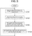
- FIG. 5 is a flowchart showing an example of a process flow of the docking assistance device 1.
- the position azimuth information acquisition unit 13 acquires the ship 2's position data and azimuth data, based on the detection results of the GNSS device 31 and the azimuth sensor 33 (step S101).
- the high-point acquisition unit 16 acquires the point group of only the high point (step S102).
- the position azimuth estimation unit 19 estimates the ship 2's position and azimuth (step S103).
- the ship 2's position and azimuth acquired in this step S103 are expected to be more accurate than the ship 2's position and azimuth acquired in step S101.
- the map generation updating unit 17 updates, in the form of adding to the map 41, the point-group data acquired at the environment information acquisition unit 15 (step S104).
- the point-group data that is added to the map 41 at this time may or may not be a high point. Then, the process returns to step S101.
- any other ship may be navigating or anchored in a harbor.
- the ship's height based on the water surface is usually higher than the dock. Therefore, the point group showing that the LIDAR 11 has detected the other ship may be recognized as a high point.
- using the other ship as a positional reference for matching is not appropriate, given the possibility of the ship to be moved.
- a known image recognizing is executed on the imaging result of the camera 12 that includes, in the field of view, the angular scanning range of the LIDAR 11, and the point group that is recognized as the other ship is excluded from the high point at the high-point acquisition unit 16.
- the high-point acquisition unit 18 In this way, excluding, from the target of matching (high point), the point that corresponds to the moving object such as a ship can preferably increase the estimation accuracy by the position azimuth estimation unit 19.
- the waves caused by the ship 2 may be detected by the LIDAR 11.
- the point group, among the point-group data 40, that is detected within a predetermined distance from the ship 2 can prevent waves by the own ship's navigating from being falsely detected as an obstacle.
- the image recognizing with the image of the camera 12 thereby to exclude, from the target for plotting on the map 41, the point group that corresponds to the portion that is recognized to be an object that is not an obstacle (for example, a wave) is allowed.
- the matching allows the position azimuth estimation unit 19 to estimate the ship 2's position and azimuth.
- the matching process converges at an extremely early stage with the information given in advance, it is preferable to input the above reference information in view of the real-time nature, etc. of the map generating.
- the cycle to acquire the ship 2's azimuth by the azimuth sensor 33 may be longer than the cycle to acquire the point-group data 40 by the LIDAR 11.
- the detecting of azimuth (or, strictly speaking, change in azimuth) by the IMU 35 can be done with a cycle shorter than the detecting of azimuth by the azimuth sensor 33.
- the attitude information acquisition unit 14 uses the detection result of the IMU 35 thereby to make it possible to acquire the relative change in azimuth from the time when the azimuth was most recently acquired by the azimuth sensor 33 to the time when the point-group data 40 was acquired by the LIDAR 11.
- correcting the azimuth most recently acquired by the azimuth sensor 33 can acquire the ship 2's azimuth at the time of acquiring the point-group data 40.
- Giving this azimuth, as reference information, to the position azimuth estimation unit 19 can accomplish the matching, in a short period, at the position azimuth estimation unit 19.
- FIG. 6 is a flowchart describing the process executed by the high-point acquisition unit 16.
- the high-point acquisition unit 16 focuses on one point included in the point-group data 40, and determines whether the height of this point is equal to a predetermined threshold h1 or more (step S201).
- h1 a predetermined threshold
- this determination can be easily made by examining the z-coordinate.
- the high-point acquisition unit 16 determines whether or not the point is a point of the portion that has been recognized as the other ship by the image recognizing of the camera 12 (step S202). This determination is for excluding, from the high point, the point that corresponds to the moving object, as described above.
- step S203 When the point does not correspond to the moving object, the high-point acquisition unit 16 adds the point to the point group of the high point (step S203).
- step S201 When it is determined in step S201 that the height of the point is less than the threshold h1, or when it is determined in step S202 that the point corresponds to the moving object, the process of step S203 is not executed.
- the high-point acquisition unit 16 repeats the processes of step S201 to step S203 for all the points that are included in the point-group data 40 (step S204). Then, the process is ended.
- the docking assistance device 1 of the ship 2 of the present embodiment has the position azimuth information acquisition unit 13, the LIDAR 11, the map generation updating unit 17, the high-point acquisition unit 16, and the position azimuth estimation unit 19.
- the position azimuth information acquisition unit 13 acquires the ship 2's position data that is based on the satellite positioning system.
- the LIDAR 11 acquires the point-group data 40 that three-dimensionally shows the environment around the ship 2.
- the map generation updating unit 17 Based on the point-group data 40, the map generation updating unit 17 generates the map 41 around the ship 2.
- the high-point acquisition unit 16 acquires the high point among the point-group data 40.
- the position azimuth estimation unit 19 estimates the ship 2's position and azimuth by matching the high point acquired by the high-point acquisition unit 16 with the high point in the map 41.
- the map generation updating unit 17 places the point-group data 40 on the map 41 based on the ship 2's position and azimuth estimated by the position azimuth estimation unit 19, thereby to update the map 41.
- the point-group data 40 is placed on the map 41 based on the own ship's position and azimuth estimated as a result of matching the point-group data 40 with the map 41, thus making it possible to acquire the map 41 with accuracy higher than when following the satellite positioning system. Further, since the matching is executed by excluding the object with low height, it is possible to prevent the object, that is unstable to detect, such as dock, from degrading the accuracy of estimating the ship's position and azimuth. As a result, the map 41 that is accurate can be acquired, thus making it possible to appropriately perform the docking assistance.
- the map generation updating unit 17 places the point-group data 40 on the map 41 regardless of a high point or not.
- the high-point acquisition unit 16 excludes, from the target to be acquired as a high point, the point-group data 40's portion that corresponds to the portion determined to be the moving object by the image recognizing of the imaging result of the camera 12 included in the ship 2.
- the accuracy of estimating the ship 2's position and azimuth can be prevented from being degraded by the matching that is based on the moving object (for example, another ship).
- the map generation updating unit 17 excludes, from the target to be placed on the map 41, the point-group data 40's portion having a distance from the ship 2 closer than the predetermined distance.
- the position azimuth estimation unit 19 estimates the ship 2's position and azimuth
- the ship 2's position data acquired by the position azimuth information acquisition unit 13 is input to the position azimuth estimation unit 19.
- the position azimuth information acquisition unit 13 can acquire the azimuth data in addition to the ship 2's position data.
- the position azimuth estimation unit 19 estimates the ship 2's position and azimuth
- the ship 2's position data and azimuth data acquired by the position azimuth information acquisition unit 13 are input to the position azimuth estimation unit 19.
- the position azimuth information acquisition unit 13 acquires the ship 2's azimuth data that is based on the satellite positioning system. Further, the position azimuth information acquisition unit 13 also functions as an azimuth change acquisition unit that acquires the relative change in the ship 2's azimuth based on the IMU 35.
- the ship 2's azimuth data acquired by the position azimuth information acquisition unit 13 is corrected based on the result of acquiring, with the azimuth change acquisition unit, the relative change in the ship 2's azimuth from the time of acquiring the azimuth data to the time of acquiring the point-group data 40, and thereafter the corrected azimuth data is input to the position azimuth estimation unit 19.
- the docking assistance device 1 of the ship 2 of the present embodiment includes the attitude information acquisition unit 14 capable of acquiring the ship 2's attitude in at least the pitch direction and roll direction. Based on the ship 2's attitude acquired by the attitude information acquisition unit 14, the point-group data 40 is corrected so as to remove the influence of the ship 2's attitude.
- the docking assistance device 1 of the ship 2 of the present embodiment includes the automatic docking control unit 21. Based on the map 41 updated by the map generation updating unit 17, the automatic docking control unit 21 executes the automatic docking control of the ship 2.
- the process of excluding, from the high point, the point, among the point-group data 40, that is recognized as the moving object can be omitted.
- the process of excluding, from the plot on the map 41, the point-group data 40's point that is closer from the ship 2 than the predetermined distance can be omitted.
- the map generation updating unit 17 may generate a two-dimensional map instead of the three-dimensional map 41.
- the matching of the high point may be done two-dimensionally in the position azimuth estimation unit 19.
- the automatic docking control unit 21 may be omitted. Even when the automatic ship maneuvering is not executed, displaying the map 41 on the display of the interface unit 22, for example, can assist the operator in maneuvering the ship for docking. A route from the current position of the own ship to the target docking position may be generated and displayed on the automatic docking control unit 21.
- the position for mounting the LIDAR 11 on the ship 2 is optional, and the LIDAR 11 can be mounted on the bow, stern, side of the hull, the upper portion of the cockpit, etc.
- the position for mounting the camera 12 on the ship 2 is optional, and the camera 12 can be mounted on the bow, stern, side of the hull, the upper portion of the cockpit, etc.
- the propulsion unit 5 is configured so as to allow the direction of the rotation axis of each of the screws 6L, 6R to be changed independently.
- the method of the propulsion unit 5 can be modified to any other method as long as being able to substantially accomplish the lateral parallel movement and the in-situ rotation, etc. of the ship 2.
- the propulsion unit 5 includes a pair of right and left screws that cannot change the direction of the rotation axis, a rudder, and a side thruster that is provided on the bow side.
- the propulsion unit 5 can include a single screw that cannot change the direction of the rotation axis, a rudder, and side thrusters provided on the respective bow and stern sides.
Landscapes
- Engineering & Computer Science (AREA)
- Remote Sensing (AREA)
- Radar, Positioning & Navigation (AREA)
- Physics & Mathematics (AREA)
- General Physics & Mathematics (AREA)
- Automation & Control Theory (AREA)
- Aviation & Aerospace Engineering (AREA)
- Ocean & Marine Engineering (AREA)
- Life Sciences & Earth Sciences (AREA)
- Theoretical Computer Science (AREA)
- Mechanical Engineering (AREA)
- Combustion & Propulsion (AREA)
- Chemical & Material Sciences (AREA)
- Business, Economics & Management (AREA)
- Atmospheric Sciences (AREA)
- Environmental & Geological Engineering (AREA)
- Educational Technology (AREA)
- Educational Administration (AREA)
- Mathematical Physics (AREA)
- Ecology (AREA)
- Navigation (AREA)
- Traffic Control Systems (AREA)
- Instructional Devices (AREA)
Abstract

Description
- The present invention relates to a ship docking assistance device.
- Conventionally, it is known that a ship docking assistance device acquires the ship's position data based on a satellite positioning system in order for the ship to dock.
Patent Literature 1 discloses this type of ship docking assistance device. - The ship docking assistance device in
Patent Literature 1 has a GPS mounted to the ship. This ship docking assistance device can calculate the ship's own position from the GPS. The ship docking assistance device ofPatent Literature 1 inputs, to a signal processing unit, a position signal by the latitude and longitude output from the GPS. The position signal by the GPS, the signal output from a millimeter wave radar, and the chart data input to the signal processing unit in advance are used to determine the positional relation between the ship and the wharf or dock. - Patent Literature 1:
Japanese Patent No. 5431141 - For calculating the ship's own position, the ship docking assistance device in
Patent Literature 1 uses the GPS, a type of GNSS. However, the ship's own position calculated by the GPS alone often has a certain great error relative to the ship's actual own position. Therefore, it was difficult to accurately acquire the positional relation between the ship and the wharf or dock. As a result, for example, when attempting to automatically dock the ship at the wharf or the like using the ship's own position, it may not be possible to properly dock the ship at a target docking position. - The present invention has been made in view of the above circumstances, and it is an object of the present invention to provide a ship docking assistance device that can accurately acquire the position of a ship.
- The problem to be solved by the present invention is as described above, and next, the means for solving this problem and an effect thereof will be described.
- According to an aspect of the present invention, a ship docking assistance device having the following configuration is provided. That is, this ship docking assistance device includes a position acquisition unit, a surrounding environment sensor, a map generation unit, a landmark position acquisition unit, and an estimation unit. The position acquisition unit acquires a ship's position data that is based on a satellite positioning system. The surrounding environment sensor acquires surrounding environment data that shows an environment around the ship in three dimensions. The map generator generates a map around the ship based on the surrounding environment data. The landmark position acquisition unit acquires a position of a landmark that is, among the surrounding environment data, an object of a predetermined height or more. The estimation unit estimates the ship's position and azimuth by matching the landmark position acquired by the landmark position acquisition unit, with the landmark's position in the map. The map generation unit places the surrounding environment data on the map based on the ship's position and azimuth estimated by the estimation unit, thereby to update the map.
- With this, the surrounding environment data is placed on the map based on the own ship's position and azimuth estimated as a result of matching the surrounding environment data with the map, thus making it possible to acquire the map with accuracy higher than when following the satellite positioning system. Further, since the matching is executed by excluding the object with low height, it is possible to prevent the object, that is unstable to detect (for example, dock), from degrading the accuracy of estimating the ship's position and azimuth. As a result, a map that is accurate can be acquired, thus making it possible to appropriately perform a docking assistance.
- In the ship docking assistance device, the map generation unit places the surrounding environment data on the map regardless of whether the surrounding environment data corresponds to the landmark or not.
- With this, regardless of whether the surrounding object is high or low, use of the map can prevent from physically contacting the object.
- It is preferable that, in the ship docking assistance device, the following configuration is made. That is, the landmark position acquisition unit excludes, from a target to be acquired as the landmark's position, the surrounding environment data's portion that corresponds to a portion that is determined to be a moving object by image recognizing of an imaging result of a camera included in the ship.
- With this, the accuracy of estimating the ship's position and azimuth can be prevented from being degraded by the matching that is based on the moving object.
- It is preferable that, in the ship docking assistance device, the map generation unit excludes, from a target to be placed on the map, the surrounding environment data's portion having a distance from the ship closer than a predetermined distance.
- This can prevent, for example, waves, which are caused by the movement of the ship, from being treated as obstacles.
- It is preferable that, in the ship docking assistance device, when the estimation unit estimates the ship's position and azimuth, the ship's position data acquired by the position acquisition unit is input to the estimation unit.
- This gives, to the estimation unit, a clue as to the ship's position, thus making it possible to estimate the ship's position and azimuth with a small calculation amount and in a short time.
- It is preferable that, in the ship docking assistance device, the following configuration is made. That is, the ship docking assistance device includes an azimuth acquisition unit that acquires the ship's azimuth data. When the estimation unit estimates the ship's position and azimuth, the ship's position data acquired by the position acquisition unit and the ship's azimuth data acquired by the azimuth acquisition unit are input to the estimation unit.
- This gives, to the estimation unit, the clue as to the ship's position and azimuth, thus making it possible to estimate the ship's position and azimuth with a smaller calculation amount and in a short time.
- It is preferable that, in the ship docking assistance device, the following configuration is made. That is, the azimuth acquisition unit acquires the ship's azimuth data that is based on the satellite positioning system. The docking assistance device includes an azimuth change acquisition unit that acquires a relative change in the ship's azimuth. The ship's azimuth data acquired by the azimuth acquisition unit is corrected based on a result of acquiring, with the azimuth change acquisition unit, the relative change in the ship's azimuth from a time of acquiring the azimuth data to a time of acquiring the surrounding environment data, and thereafter the corrected azimuth data is input to the estimation unit.
- This accomplishes that even when the time interval for the azimuth acquisition unit to acquire the azimuth that is based on the satellite positioning cannot be shortened, using the azimuth change acquisition unit makes it possible to give, in a sufficiently short time interval, to the estimation unit, the clue as to the ship's azimuth.
- It is preferable that, in the ship docking assistance device, the following configuration is made. That is, the ship docking assistance device includes an attitude acquisition unit capable of acquiring the ship's attitude in at least a pitch direction and a roll direction. Based on the ship's attitude acquired by the attitude acquisition unit, the surrounding environment data is corrected so as to remove an influence of the ship's attitude.
- This can remove the influence caused to the surrounding environment data due to the rocking of the ship. As a result, the matching and the surrounding environment data's placing can be accurately done, thus making it possible to acquire the map with high accuracy.
- It is preferable that, in the ship docking assistance device, an automatic docking control of the ship is executed based on the map updated by the map generation unit.
- This allows the automatic docking control to be executed based on the accurate map.
-
- [
FIG. 1] FIG. 1 is a block diagram showing an electrical configuration of a ship docking assistance device according to one embodiment of the present invention. - [
FIG. 2] FIG. 2 is a schematic diagram illustrating the matching between a high point of a point-group data acquired by a LIDAR and a high point of a map. - [
FIG. 3] FIG. 3 is a schematic diagram illustrating a process of adding point-group data to the map. - [
FIG. 4] FIG. 4 is a schematic diagram illustrating the relation between the LIDAR and a dock. - [
FIG. 5] FIG. 5 is a flowchart showing a process of generating and updating the map. - [
FIG. 6] FIG. 6 is a flowchart showing a process for extracting the high point. - Then, embodiments of the present invention will be described referring to drawings.
FIG. 1 shows a block diagram showing an electrical configuration of adocking assistance device 1 for aship 2 according to one embodiment of the present invention. - The ship docking assistance device (hereinafter simply referred to as docking assistance device) 1 shown in
FIG. 1 is used on board theship 2. The term "docking" as used herein includes the case where theship 2 is docking on a wharf, and the case where theship 2 is docking on a structure such as a dock. - Configuration of the
ship 2 to which thedocking assistance device 1 is applied is not limited. For example, theship 2 can be a pleasure boat, fishing ship, water-jet ship, electric propulsion ship, hybrid ship, etc. - The
ship 2 includes apropulsion unit 5. - A
propulsion unit 5 includes a pair ofscrews screws ship 2. Thepropulsion unit 5 can rotate thescrews screws respective screws respective screws ship 2. - Further, the configuration of the
propulsion unit 5 is not particularly limited. For example, thescrews screws - The
docking assistance device 1 of theship 2 has acontrol unit 10, a LIDAR (surrounding environment sensor) 11, and acamera 12. Thecontrol unit 10 includes a position azimuth information acquisition unit (position acquisition unit, azimuth acquisition unit) 13, an attitude information acquisition unit (attitude acquisition unit, azimuth change acquisition unit) 14, an environmentinformation acquisition unit 15, a high-point acquisition unit (landmark position acquisition unit) 16, a map generation updating unit (map generation unit) 17, a high-point acquisition unit 18, a position azimuth estimation unit (estimation unit) 19, a displaydata generation unit 20, automaticdocking control unit 21, and aninterface unit 22. - The
control unit 10 is configured as a computer including CPU, ROM and RAM. The ROM stores various programs, etc., including a program for operating thedocking assistance device 1. The CPU can read various programs, etc. from the ROM and execute them. In cooperation with the above hardware and software, thecontrol unit 10 can function as the position azimuthinformation acquisition unit 13, the attitudeinformation acquisition unit 14, the environmentinformation acquisition unit 15, the high-point acquisition unit 16, the mapgeneration updating unit 17, the high-point acquisition unit 18, the positionazimuth estimation unit 19, the displaydata generation unit 20, the automaticdocking control unit 21, and theinterface unit 22. - The
LIDAR 11 can acquire any surrounding environment data indicating the environment around theship 2. TheLIDAR 11 is placed at an appropriate position (for example, bow) of theship 2. TheLIDAR 11 has a light emitting unit and a light receiving unit. The light-emitting unit irradiates pulsed light (laser light) outside the visible spectrum range, and the light receiving unit receives the reflected light that is the pulsed light reflected by the object. Based on the time between the irradiating of the pulsed light and the receiving of the reflected light, theLIDAR 11 detects the presence or absence of an object around theship 2 and, with the object being present, the distance to the object. - The
LIDAR 11 emits and receives the light while (substantially) changing the direction of the pulsed light at a predetermined angular interval. This makes it possible to measure the distance to the object around theship 2 at every predetermined angle. Such angular scanning may be accomplished, for example, by mechanically adjusting the directions of the light emitting unit and light receiving unit, by a MEMS (micro-electromechanical systems), or by a known phased array method. - In the present embodiment, the
LIDAR 11 is configured as a three-dimensional LIDAR that executes the angular scanning in the yaw and pitch directions. This angular scanning allows theLIDAR 11 to output three-dimensional point-group data (surrounding environment data) 40 that represents an object present around theLIDAR 11.FIG. 2(a) shows an example of the point-group data 40 in the form of a plan view, and theship 2's position and azimuth acquired by theGNSS device 31 and theazimuth sensor 33. - The
camera 12 can generate imaged data by taking pictures of the surrounding of theship 2, and can output this imaged data. Thecamera 12 is placed at an appropriate position on the ship 2 (for example, bow). It is preferable that thecamera 12 be installed in the vicinity of theLIDAR 11 and in such a manner as to have the shooting direction of thecamera 12 coincide with the center of the angular scanning range of theLIDAR 11, since the above installing can easily make the point-group data 40 of theLIDAR 11 correspond to the imaged data of thecamera 12. - The position azimuth
information acquisition unit 13 can acquire theship 2's position data acquired by theGNSS device 31 included in theship 2. Further, the position azimuthinformation acquisition unit 13 can acquire theship 2's azimuth data acquired by theazimuth sensor 33 included in theship 2. - The
GNSS device 31 receives GNSS radio wave from a satellite and executes a known positioning calculation, thereby to acquire theship 2's current position. Therefore, the position data acquirable by theGNSS device 31 is based on the satellite positioning system. In the present embodiment, stand-alone positioning is used as the GNSS positioning, but any known DGNSS positioning and an RTK (Real Time Kinematic) positioning can also be used. - The
azimuth sensor 33 can acquire the azimuth of the bow of theship 2. Theazimuth sensor 33 includes a satellite compass in the present embodiment. Since the configuration of the satellite compass is known, any detail thereof is to be omitted, but the satellite compass includes multiple GNSS antennas and can detect the azimuth based on the route difference of carrier wave of GNSS radio wave. Therefore, the azimuth data acquired by theazimuth sensor 33 is based on the satellite positioning system. Theazimuth sensor 33 is not limited to this, for example, and can be a magnetic azimuth sensor. - The attitude
information acquisition unit 14 can acquire the data (data related to theship 2's attitude) output by theIMU 35 included in theship 2. The IMU is an abbreviation of inertial measurement unit. - The
IMU 35, which includes an accelerometer, can acquire three-dimensional acceleration. Further, theIMU 35, which includes a gyro sensor, can calculate the three-dimensional angular speed. The above can acquire theship 2's attitude (roll angle, pitch angle, and yaw angle). The gyro sensor can have various known configurations, such as a ring laser gyro. - The environment
information acquisition unit 15 can acquire surrounding environment data (specifically, three-dimensional point-group data 40) acquired by theLIDAR 11. However, since theLIDAR 11 acquires the point-group data 40 in the form of a relative angle and a relative distance to its own device, the position of the point-group data 40 varies depending on the attitude of theship 2 to which theLIDAR 11 is mounted. Then, from the attitudeinformation acquisition unit 14, the environmentinformation acquisition unit 15 first acquires theship 2's attitude at the timing when theLIDAR 11 acquires the point-group data 40. Based on this attitude information and on the point group acquired by theLIDAR 11, the environmentinformation acquisition unit 15 calculates the position of the point group in the case where theship 2 is temporarily at a predetermined angle in the roll and pitch directions (for example, in the case of being horizontal). This converting process can be easily executed by a known geometric calculation. The above can remove any influence, of theship 2's attitude (roll angle and pitch angle), on the three-dimensional point-group data 40. - The high-
point acquisition unit 16 extracts the point, among the three-dimensional point-group data 40 input from the environmentinformation acquisition unit 15, that is positioned higher than a predetermined height. Hereafter, the point extracted with this may be referred to as high point. The fact that an object is placed at a high place can be considered as a type of geographical feature, so the high point can be said to indicate the position of a landmark. A threshold of the height to be extracted as a high point can be appropriately determined, and details thereof will be described below. - The map
generation updating unit 17 generates a map around theship 2 using the three-dimensional point-group data 40 input from the environmentinformation acquisition unit 15 and theship 2's position and azimuth input from the positionazimuth estimation unit 19. The map can be generated, for example, by plotting the point-group data 40 in a three-dimensional space.FIG. 2(b) shows an example of the generatedmap 41. However, inFIG. 2(b) , the point-group data 40 is drawn in a manner to be superimposed on themap 41 so as to illustrate the below-described matching executed by the positionazimuth estimation unit 19. - The
ship 2's position and azimuth used as a reference for the mapgeneration updating unit 17 to plot the point-group data 40 on themap 41 include the below-describedship 2's position and azimuth output by the positionazimuth estimation unit 19, not the output of theGNSS device 31 and theazimuth sensor 33. This can increase the accuracy of the generatedmap 41. Details will be described below. - From the
map 41 generated by the mapgeneration updating unit 17, the high-point acquisition unit 18 extracts the point that is positioned higher than a predetermined height (high point). It is preferable that the threshold of the height of the high point is equal to the threshold in the high-point acquisition unit 16. - The position
azimuth estimation unit 19 estimates theship 2's position and azimuth by the matching of the high point input from the high-point acquisition unit 16 with the high point input from the high-point acquisition unit 18. - As described above, the
ship 2's position and azimuth output by theGNSS device 31 and theazimuth sensor 33 include a certain error. Therefore, if themap 41 should be generated in the form of plotting the point-group data 40 of theLIDAR 11 using the GNSS positioning result as it is, the plot of the point-group data 40 will be misaligned as shown inFIG. 2(b) , thus degrading the positional accuracy of the point group included in themap 41. In this respect, the positionazimuth estimation unit 19 can acquire the accurate position and theship 2's azimuth by matching the high point stored as themap 41 by the mapgeneration updating unit 17 with the high point that is based on the detection result of theLIDAR 11. Based on the above position and azimuth, the mapgeneration updating unit 17 places the point-group data 40 of the LIDAR, thus making it possible to acquire an accurate map as shown inFIG. 3 . With this, a type of SLAM is executed in the present embodiment. SLAM is an abbreviation of Simultaneous Localization AND Mapping. - The method of matching the high points together can be, but is not limited to, a known ICP matching. ICP is an abbreviation of Iterative Closest Point. At the time of calculating the matching; using, as reference information, the
ship 2's position and azimuth output by theGNSS device 31 and theazimuth sensor 33 is preferable, because the above using can reduce the calculation amount. - Generally speaking in terms of the matching of the point group, the higher the number of matching points, the higher the accuracy of estimating the position and azimuth. However, in the present embodiment, the target of matching is limited to the high point only.
- The reason for this is to be described in detail below. For this description, assume a situation where a
dock 51 is present near theship 2, as shown inFIG. 4(a) or FIG. 4(b) . InFIG. 4(b) , a structure having a certain height (specifically, apower supply post 52 for charging the ship 2) is provided protruding upward on thedock 51. - A first reason is instability of detecting the
dock 51. Thedock 51 is placed close to the water surface; therefore, as shown inFIG. 4(a) , thedock 51 is often detected near the lower end in the angular scanning range in the pitch direction of theLIDAR 11. Therefore, for example, theship 2, when swaying (heaving) in the height direction as shown by a white arrow a makes it easier for thedock 51 to move in and out of the angular scanning range of theLIDAR 11. As a result, by theLIDAR 11, sometimes thedock 51 is detected, and at other times thedock 51 is not detected. This instability in detecting the point group leads to a degradation in the accuracy of theship 2's position and azimuth estimated by the positionazimuth estimation unit 19. Meanwhile, since thepower supply post 52 has a certain height as shown inFIG. 4(b) , it is possible to securely perform the detecting with theLIDAR 11, despite the heave of theship 2. - A second reason is the shape of the
dock 51. Most of thedocks 51 are each formed in the form of a substantially horizontal floor, close to the water surface. Meanwhile, theLIDAR 11 is mounted to a position at a certain height on theship 2. Therefore, a laser beam of theLIDAR 11 will most likely hit the floor ofdock 51. From the above, it is difficult, when theship 2 has moved in the horizontal direction in the example ofFIG. 4(a) , to accurately detect the movement of theship 2, from the change in the position of the point group showing that thedock 51's floor which is a face substantially parallel to the movement direction has been detected. Meanwhile, thepower supply post 52 shown inFIG. 4(b) has many faces that are close to being vertical to the horizontal direction. Therefore, the horizontal movement of theship 2 can be easily captured as a change in the position of the point group acquired by theLIDAR 11. - In view of these circumstances, the position
azimuth estimation unit 19 of the present embodiment excludes, from the matching target, the point group that corresponds to the low structure such as thedock 51, and executes the matching based only on the point group that corresponds to the structure of a certain height or more such as thepower supply post 52. This makes it possible to estimate, with high accuracy, theship 2's position and azimuth. Further, since the number of point groups is reduced by narrowing down the matching targets, reduction in the calculation amount can be accomplished. - Therefore, the threshold of the height extracted as a high point at the high-
point acquisition unit 16 and high-point acquisition unit 18 may be set to an appropriate value that is higher than thedock 51's height above water and lower than thepower supply post 52, etc.'s height above water.FIG. 4(b) shows an example of a threshold h1 of height. - The display
data generation unit 20 can generate display data to show theship 2's position, themap 41 around theship 2, the target docking position, etc. The display data is shown on the display as described below. The display data can be, for example, data for showing theship 2 at its current position as a symbolic figure, and for showing an obstacle, etc. as a predetermined point figure. - The automatic
docking control unit 21 generates a route for theship 2 to reach the target docking position, and controls thescrews ship 2 to be automatically docked. Theship 2's position and azimuth estimated by the positionazimuth estimation unit 19 and themap 41 generated and updated by the mapgeneration updating unit 17 are used for the route generating and the automatic ship maneuver. - The
interface unit 22 has a user interface function in thedocking assistance device 1. Theinterface unit 22 can be configured so as to include, for example, a display and an input device. In this case, the user can input an instruction by referring to the content of the display and operating the input device. The input device may be a keyboard, mouse, or touch screen. - Next, referring to
FIG. 5 , processes for generating and updating themap 41 will be described in detail.FIG. 5 is a flowchart showing an example of a process flow of thedocking assistance device 1. - With the process started, the position azimuth
information acquisition unit 13 acquires theship 2's position data and azimuth data, based on the detection results of theGNSS device 31 and the azimuth sensor 33 (step S101). - Next, from the
LIDAR 11's point-group data 40 acquired at the environmentinformation acquisition unit 15, the high-point acquisition unit 16 acquires the point group of only the high point (step S102). - Then, matching the point group of the high point acquired in step S102 with the point group of the high point in the
map 41 that has already been generated at the mapgeneration updating unit 17, the positionazimuth estimation unit 19 estimates theship 2's position and azimuth (step S103). Theship 2's position and azimuth acquired in this step S103 are expected to be more accurate than theship 2's position and azimuth acquired in step S101. - Then, with reference to the
ship 2's position and azimuth estimated in step S103, the mapgeneration updating unit 17 updates, in the form of adding to themap 41, the point-group data acquired at the environment information acquisition unit 15 (step S104). The point-group data that is added to themap 41 at this time may or may not be a high point. Then, the process returns to step S101. - Next, description will be made of the point-
group data 40 that is processed based on image recognizing by thecamera 12. - Any other ship may be navigating or anchored in a harbor. The ship's height based on the water surface is usually higher than the dock. Therefore, the point group showing that the
LIDAR 11 has detected the other ship may be recognized as a high point. However, using the other ship as a positional reference for matching is not appropriate, given the possibility of the ship to be moved. Then, in the present embodiment, a known image recognizing is executed on the imaging result of thecamera 12 that includes, in the field of view, the angular scanning range of theLIDAR 11, and the point group that is recognized as the other ship is excluded from the high point at the high-point acquisition unit 16. The same is true for the high-point acquisition unit 18. In this way, excluding, from the target of matching (high point), the point that corresponds to the moving object such as a ship can preferably increase the estimation accuracy by the positionazimuth estimation unit 19. - Then, description will be made of the point-
group data 40 processed based on the distance from the own ship. - For example, when the
ship 2 is navigating at a certain speed, the waves caused by theship 2 may be detected by theLIDAR 11. Excluding, from the target for plotting on themap 41, the point group, among the point-group data 40, that is detected within a predetermined distance from theship 2 can prevent waves by the own ship's navigating from being falsely detected as an obstacle. Performing the image recognizing with the image of thecamera 12 thereby to exclude, from the target for plotting on themap 41, the point group that corresponds to the portion that is recognized to be an object that is not an obstacle (for example, a wave) is allowed. - Then, description will be made of the configuration for inputting, to the position
azimuth estimation unit 19, data on the own ship's position and azimuth. - Giving, to the position
azimuth estimation unit 19, theship 2's position acquired by theGNSS device 31 and theship 2's azimuth acquired by theazimuth sensor 33, as reference information, is not a must. Even without the above information, the matching allows the positionazimuth estimation unit 19 to estimate theship 2's position and azimuth. However, since the matching process converges at an extremely early stage with the information given in advance, it is preferable to input the above reference information in view of the real-time nature, etc. of the map generating. - In some configurations, the cycle to acquire the
ship 2's azimuth by theazimuth sensor 33 may be longer than the cycle to acquire the point-group data 40 by theLIDAR 11. Meanwhile, the detecting of azimuth (or, strictly speaking, change in azimuth) by theIMU 35 can be done with a cycle shorter than the detecting of azimuth by theazimuth sensor 33. Using this, the attitudeinformation acquisition unit 14 uses the detection result of theIMU 35 thereby to make it possible to acquire the relative change in azimuth from the time when the azimuth was most recently acquired by theazimuth sensor 33 to the time when the point-group data 40 was acquired by theLIDAR 11. Based on this relative change in azimuth, correcting the azimuth most recently acquired by theazimuth sensor 33 can acquire theship 2's azimuth at the time of acquiring the point-group data 40. Giving this azimuth, as reference information, to the positionazimuth estimation unit 19 can accomplish the matching, in a short period, at the positionazimuth estimation unit 19. - Next, referring to
FIG. 6 , detailed description will be made of the process where the high-point acquisition unit 16 extracts, from the point-group data 40, the point group of the high point.FIG. 6 is a flowchart describing the process executed by the high-point acquisition unit 16. - With the process started, the high-
point acquisition unit 16 focuses on one point included in the point-group data 40, and determines whether the height of this point is equal to a predetermined threshold h1 or more (step S201). When the position of the point is expressed in three-dimensional Cartesian coordinates, this determination can be easily made by examining the z-coordinate. - When the height of the point is the threshold h1 or more, the high-
point acquisition unit 16 determines whether or not the point is a point of the portion that has been recognized as the other ship by the image recognizing of the camera 12 (step S202). This determination is for excluding, from the high point, the point that corresponds to the moving object, as described above. - When the point does not correspond to the moving object, the high-
point acquisition unit 16 adds the point to the point group of the high point (step S203). When it is determined in step S201 that the height of the point is less than the threshold h1, or when it is determined in step S202 that the point corresponds to the moving object, the process of step S203 is not executed. - The high-
point acquisition unit 16 repeats the processes of step S201 to step S203 for all the points that are included in the point-group data 40 (step S204). Then, the process is ended. - As described above, the
docking assistance device 1 of theship 2 of the present embodiment has the position azimuthinformation acquisition unit 13, theLIDAR 11, the mapgeneration updating unit 17, the high-point acquisition unit 16, and the positionazimuth estimation unit 19. The position azimuthinformation acquisition unit 13 acquires theship 2's position data that is based on the satellite positioning system. TheLIDAR 11 acquires the point-group data 40 that three-dimensionally shows the environment around theship 2. Based on the point-group data 40, the mapgeneration updating unit 17 generates themap 41 around theship 2. The high-point acquisition unit 16 acquires the high point among the point-group data 40. The positionazimuth estimation unit 19 estimates theship 2's position and azimuth by matching the high point acquired by the high-point acquisition unit 16 with the high point in themap 41. The mapgeneration updating unit 17 places the point-group data 40 on themap 41 based on theship 2's position and azimuth estimated by the positionazimuth estimation unit 19, thereby to update themap 41. - With this, the point-
group data 40 is placed on themap 41 based on the own ship's position and azimuth estimated as a result of matching the point-group data 40 with themap 41, thus making it possible to acquire themap 41 with accuracy higher than when following the satellite positioning system. Further, since the matching is executed by excluding the object with low height, it is possible to prevent the object, that is unstable to detect, such as dock, from degrading the accuracy of estimating the ship's position and azimuth. As a result, themap 41 that is accurate can be acquired, thus making it possible to appropriately perform the docking assistance. - In the
docking assistance device 1 of theship 2 of the present embodiment, the mapgeneration updating unit 17 places the point-group data 40 on themap 41 regardless of a high point or not. - With this, regardless of whether the surrounding object is high or low, use of the
map 41 can prevent theship 2 from contacting the object. - In the
docking assistance device 1 of theship 2 of the present embodiment, the high-point acquisition unit 16 excludes, from the target to be acquired as a high point, the point-group data 40's portion that corresponds to the portion determined to be the moving object by the image recognizing of the imaging result of thecamera 12 included in theship 2. - With this, the accuracy of estimating the
ship 2's position and azimuth can be prevented from being degraded by the matching that is based on the moving object (for example, another ship). - In the
docking assistance device 1 of theship 2 of the present embodiment, the mapgeneration updating unit 17 excludes, from the target to be placed on themap 41, the point-group data 40's portion having a distance from theship 2 closer than the predetermined distance. - This can prevent, for example, waves, which are caused by the movement of the
ship 2, from being treated as obstacles. - In the
docking assistance device 1 of theship 2 of the present embodiment, when the positionazimuth estimation unit 19 estimates theship 2's position and azimuth, theship 2's position data acquired by the position azimuthinformation acquisition unit 13 is input to the positionazimuth estimation unit 19. - This gives, to the position
azimuth estimation unit 19, a clue as to theship 2's position, thus making it possible to estimate the ship's position and azimuth with a small calculation amount and in a short time. - In the
docking assistance device 1 of theship 2 of the present embodiment, the position azimuthinformation acquisition unit 13 can acquire the azimuth data in addition to theship 2's position data. When the positionazimuth estimation unit 19 estimates theship 2's position and azimuth, theship 2's position data and azimuth data acquired by the position azimuthinformation acquisition unit 13 are input to the positionazimuth estimation unit 19. - This gives, to the position
azimuth estimation unit 19, the clue as to theship 2's position and azimuth, thus making it possible to estimate theship 2's position and azimuth with a small calculation amount and in a short time. - In the
docking assistance device 1 of theship 2 of the present embodiment, the position azimuthinformation acquisition unit 13 acquires theship 2's azimuth data that is based on the satellite positioning system. Further, the position azimuthinformation acquisition unit 13 also functions as an azimuth change acquisition unit that acquires the relative change in theship 2's azimuth based on theIMU 35. Theship 2's azimuth data acquired by the position azimuthinformation acquisition unit 13 is corrected based on the result of acquiring, with the azimuth change acquisition unit, the relative change in theship 2's azimuth from the time of acquiring the azimuth data to the time of acquiring the point-group data 40, and thereafter the corrected azimuth data is input to the positionazimuth estimation unit 19. - This accomplishes that even when the time interval for the
azimuth sensor 33 to acquire the azimuth that is based on the satellite positioning system cannot be shortened, using theIMU 35 thereby to acquire the azimuth change makes it possible to give, in a sufficiently short time interval, to the positionazimuth estimation unit 19, the clue as to theship 2's azimuth. - The
docking assistance device 1 of theship 2 of the present embodiment includes the attitudeinformation acquisition unit 14 capable of acquiring theship 2's attitude in at least the pitch direction and roll direction. Based on theship 2's attitude acquired by the attitudeinformation acquisition unit 14, the point-group data 40 is corrected so as to remove the influence of theship 2's attitude. - This can remove the influence caused to the point-
group data 40 due to the rocking of theship 2. As a result, the matching and the point-group data 40's placing can be accurately done, thus making it possible to acquire themap 41 with high accuracy. - The
docking assistance device 1 of theship 2 of the present embodiment includes the automaticdocking control unit 21. Based on themap 41 updated by the mapgeneration updating unit 17, the automaticdocking control unit 21 executes the automatic docking control of theship 2. - This allows the automatic docking control to be executed based on the
accurate map 41. - While the description has been made of the appropriate embodiment and variations thereof, the above configuration can be modified, for example, as follows.
- The process of excluding, from the high point, the point, among the point-
group data 40, that is recognized as the moving object can be omitted. The process of excluding, from the plot on themap 41, the point-group data 40's point that is closer from theship 2 than the predetermined distance can be omitted. - Among the point group plotted on the
map 41 in the mapgeneration updating unit 17, only the point group that is not considered to be a high point may be treated as an obstacle by the automaticdocking control unit 21. - The map
generation updating unit 17 may generate a two-dimensional map instead of the three-dimensional map 41. In other words, the matching of the high point may be done two-dimensionally in the positionazimuth estimation unit 19. - The automatic
docking control unit 21 may be omitted. Even when the automatic ship maneuvering is not executed, displaying themap 41 on the display of theinterface unit 22, for example, can assist the operator in maneuvering the ship for docking. A route from the current position of the own ship to the target docking position may be generated and displayed on the automaticdocking control unit 21. - The position for mounting the
LIDAR 11 on theship 2 is optional, and theLIDAR 11 can be mounted on the bow, stern, side of the hull, the upper portion of the cockpit, etc. - The position for mounting the
camera 12 on theship 2 is optional, and thecamera 12 can be mounted on the bow, stern, side of the hull, the upper portion of the cockpit, etc. - In the above embodiment, the
propulsion unit 5 is configured so as to allow the direction of the rotation axis of each of thescrews propulsion unit 5 can be modified to any other method as long as being able to substantially accomplish the lateral parallel movement and the in-situ rotation, etc. of theship 2. For example, it is conceivable that thepropulsion unit 5 includes a pair of right and left screws that cannot change the direction of the rotation axis, a rudder, and a side thruster that is provided on the bow side. Further, thepropulsion unit 5 can include a single screw that cannot change the direction of the rotation axis, a rudder, and side thrusters provided on the respective bow and stern sides. - In view of the above teachings, it is clear that the present invention can take many modified and variant modes. Therefore, it is to be understood that, within the scope of the appended claims, the present invention may be practiced in ways other than those described herein.
-
- 1: docking assistance device
- 2: ship
- 12: camera
- 13: position azimuth information acquisition unit (position acquisition unit, azimuth acquisition unit)
- 16: high-point acquisition unit (landmark position acquisition unit) 17: map generation updating unit (map generation unit)
- 19: position azimuth estimation unit (estimation unit)
- 21: automatic docking control unit
- 40: point-group data (surrounding environment data)
Claims (9)
- A ship docking assistance device, comprising:a position acquisition unit that acquires a ship's position data that is based on a satellite positioning system;a surrounding environment sensor that acquires surrounding environment data that shows an environment around the ship in three dimensions;a map generation unit that generates a map around the ship based on the surrounding environment data;a landmark position acquisition unit that acquires a position of a landmark that is, among the surrounding environment data, an object of a predetermined height or more; andan estimation unit that estimates the ship's position and azimuth by matching the landmark's position acquired by the landmark position acquisition unit, with the landmark's position in the map,wherein
the map generation unit places the surrounding environment data on the map based on the ship's position and azimuth estimated by the estimation unit, thereby to update the map. - The ship docking assistance device according to claim 1,
wherein the map generation unit places the surrounding environment data on the map regardless of whether the surrounding environment data corresponds to the landmark or not. - The ship docking assistance device according to claim 1 or 2,
wherein the landmark position acquisition unit excludes, from a target to be acquired as the landmark's position, the surrounding environment data's portion that corresponds to a portion that is determined to be a moving object by image recognizing of an imaging result of a camera included in the ship. - The ship docking assistance device according to any one of claims 1 to 3,
wherein the map generation unit excludes, from a target to be placed on the map, the surrounding environment data's portion having a distance from the ship closer than a predetermined distance. - The ship docking assistance device according to any one of claims 1 to 4,
wherein when the estimation unit estimates the ship's position and azimuth, the ship's position data acquired by the position acquisition unit is input to the estimation unit. - The ship docking assistance device according to claim 5, comprising:an azimuth acquisition unit that acquires the ship's azimuth data, wherein,when the estimation unit estimates the ship's position and azimuth, the ship's position data acquired by the position acquisition unit and the ship's azimuth data acquired by the azimuth acquisition unit are input to the estimation unit.
- The ship docking assistance device according to claim 6, wherein the azimuth acquisition unit acquires the ship's azimuth data that is based on the satellite positioning system,the ship docking assistance device comprises an azimuth change acquisition unit that acquires a relative change in the ship's azimuth, andthe ship's azimuth data acquired by the azimuth acquisition unit is corrected based on a result of acquiring, by the azimuth change acquisition unit, the relative change in the ship's azimuth from a time of acquiring the azimuth data to a time of acquiring the surrounding environment data, and thereafter the corrected azimuth data is input to the estimation unit.
- The ship docking assistance device according to any one of claims 1 to 7, comprising:an attitude acquisition unit capable of acquiring the ship's attitude in at least a pitch direction and a roll direction,wherein
based on the ship's attitude acquired by the attitude acquisition unit, the surrounding environment data is corrected so as to remove an influence of the ship's attitude. - The ship docking assistance device according to any one of claims 1 to 8,
wherein an automatic docking control of the ship is executed based on the map updated by the map generation unit.
Applications Claiming Priority (2)
| Application Number | Priority Date | Filing Date | Title |
|---|---|---|---|
| JP2019196693A JP7175252B2 (en) | 2019-10-29 | 2019-10-29 | Ship docking support device |
| PCT/JP2020/039603 WO2021085274A1 (en) | 2019-10-29 | 2020-10-21 | Ship docking assistance device |
Publications (2)
| Publication Number | Publication Date |
|---|---|
| EP4053822A1 true EP4053822A1 (en) | 2022-09-07 |
| EP4053822A4 EP4053822A4 (en) | 2023-12-06 |
Family
ID=75713243
Family Applications (1)
| Application Number | Title | Priority Date | Filing Date |
|---|---|---|---|
| EP20881714.8A Pending EP4053822A4 (en) | 2019-10-29 | 2020-10-21 | Ship docking assistance device |
Country Status (4)
| Country | Link |
|---|---|
| US (2) | US12481297B2 (en) |
| EP (1) | EP4053822A4 (en) |
| JP (1) | JP7175252B2 (en) |
| WO (1) | WO2021085274A1 (en) |
Cited By (2)
| Publication number | Priority date | Publication date | Assignee | Title |
|---|---|---|---|---|
| WO2024057826A1 (en) * | 2022-09-15 | 2024-03-21 | Furuno Electric Co., Ltd. | Navigation supporting device, navigation supporting system, navigation supporting method, and navigation supporting program |
| US12392617B2 (en) | 2022-01-14 | 2025-08-19 | Yamaha Hatsudoki Kabushiki Kaisha | Water area object detection system, marine vessel, and surrounding object detection system |
Families Citing this family (14)
| Publication number | Priority date | Publication date | Assignee | Title |
|---|---|---|---|---|
| JP7396937B2 (en) * | 2020-03-12 | 2023-12-12 | ヤンマーパワーテクノロジー株式会社 | Map generation method and map generation device |
| JP7750661B2 (en) * | 2021-03-09 | 2025-10-07 | パイオニア株式会社 | Information processing device, control method, program, and storage medium |
| JP7755419B2 (en) * | 2021-09-09 | 2025-10-16 | 川崎重工業株式会社 | Information processing device, ship steering support system |
| JP7686508B2 (en) * | 2021-09-10 | 2025-06-02 | パイオニア株式会社 | Information processing device, control method, program, and storage medium |
| KR102406661B1 (en) * | 2021-12-07 | 2022-06-08 | 엘케이시스(주) | Method and Apparatus for Matching Ship Map And Harbor Map |
| US12065230B1 (en) | 2022-02-15 | 2024-08-20 | Brunswick Corporation | Marine propulsion control system and method with rear and lateral marine drives |
| WO2023176653A1 (en) * | 2022-03-15 | 2023-09-21 | パイオニア株式会社 | Information processing device, control method, program, and storage medium |
| EP4494997A4 (en) * | 2022-03-15 | 2025-12-31 | Pioneer Corp | INFORMATION PROCESSING DEVICE, CONTROL METHOD, PROGRAM AND STORAGE MEDIUM |
| CN119053512A (en) * | 2022-03-15 | 2024-11-29 | 日本先锋公司 | Information processing device, control method, program, and storage medium |
| JP2023144818A (en) * | 2022-03-28 | 2023-10-11 | 五洋建設株式会社 | Vessel rocking suppression system, method and program |
| US12258115B2 (en) | 2022-07-20 | 2025-03-25 | Brunswick Corporation | Marine propulsion system and joystick control method |
| US12134454B1 (en) | 2022-07-20 | 2024-11-05 | Brunswick Corporation | Marine propulsion system and method with single rear drive and lateral marine drive |
| US12110088B1 (en) | 2022-07-20 | 2024-10-08 | Brunswick Corporation | Marine propulsion system and method with rear and lateral marine drives |
| CN121399429A (en) * | 2023-06-27 | 2026-01-23 | 三菱电机株式会社 | Automatic landing device, automatic landing system, automatic landing method, and automatic landing program |
Family Cites Families (21)
| Publication number | Priority date | Publication date | Assignee | Title |
|---|---|---|---|---|
| US3870992A (en) * | 1972-04-26 | 1975-03-11 | Aii Systems | Radar system |
| US3960048A (en) | 1975-03-28 | 1976-06-01 | Illinois Tool Works Inc. | Fastener assembly for creating accurate tension indicating fastener and method of calibrating the same |
| GB0616688D0 (en) * | 2006-08-23 | 2006-10-04 | Qinetiq Ltd | Target orientation |
| US9354343B2 (en) * | 2009-03-09 | 2016-05-31 | Ion Geophysical Corporation | Declination compensation for seismic survey |
| JP5431141B2 (en) * | 2009-12-18 | 2014-03-05 | ヤンマー株式会社 | Ship berthing support device |
| US9195914B2 (en) * | 2012-09-05 | 2015-11-24 | Google Inc. | Construction zone sign detection |
| US11899465B2 (en) * | 2014-12-31 | 2024-02-13 | FLIR Belgium BVBA | Autonomous and assisted docking systems and methods |
| US11328155B2 (en) * | 2015-11-13 | 2022-05-10 | FLIR Belgium BVBA | Augmented reality labels systems and methods |
| EP3497405B1 (en) * | 2016-08-09 | 2022-06-15 | Nauto, Inc. | System and method for precision localization and mapping |
| JP6821154B2 (en) * | 2016-11-16 | 2021-01-27 | 株式会社岩根研究所 | Self-position / posture setting device using a reference video map |
| US20180238690A1 (en) * | 2017-02-17 | 2018-08-23 | The Charles Stark Draper Laboratory, Inc. | Stellar-Landscape/Horizon Image Navigation |
| JP6880822B2 (en) * | 2017-02-24 | 2021-06-02 | 株式会社リコー | Equipment, mobile equipment and methods |
| US10107627B2 (en) * | 2017-03-08 | 2018-10-23 | Northrop Grumman Systems Corporation | Adaptive navigation for airborne, ground and dismount applications (ANAGDA) |
| GB2601644B (en) * | 2017-04-28 | 2023-02-08 | FLIR Belgium BVBA | Video and image chart fusion systems and methods |
| JP7074438B2 (en) * | 2017-09-05 | 2022-05-24 | トヨタ自動車株式会社 | Vehicle position estimation device |
| US11450026B2 (en) * | 2017-12-27 | 2022-09-20 | Sony Corporation | Information processing apparatus, information processing method, and mobile object |
| JP6923739B2 (en) * | 2018-02-28 | 2021-08-25 | 古野電気株式会社 | Navigation equipment, VSLAM correction method, spatial information estimation method, VSLAM correction program, and spatial information estimation program |
| US11277956B2 (en) * | 2018-07-26 | 2022-03-22 | Bear Flag Robotics, Inc. | Vehicle controllers for agricultural and industrial applications |
| US11609574B2 (en) * | 2018-11-13 | 2023-03-21 | FLIR Belgium BVBA | Extrinsic sensor calibration systems and methods |
| US11555927B2 (en) * | 2019-02-05 | 2023-01-17 | Honda Motor Co., Ltd. | System and method for providing online multi-LiDAR dynamic occupancy mapping |
| US20230334850A1 (en) * | 2019-03-22 | 2023-10-19 | Condor Acquisition Sub Ii, Inc. | Map data co-registration and localization system and method |
-
2019
- 2019-10-29 JP JP2019196693A patent/JP7175252B2/en active Active
-
2020
- 2020-10-21 WO PCT/JP2020/039603 patent/WO2021085274A1/en not_active Ceased
- 2020-10-21 US US17/773,481 patent/US12481297B2/en active Active
- 2020-10-21 EP EP20881714.8A patent/EP4053822A4/en active Pending
-
2025
- 2025-10-22 US US19/365,727 patent/US20260044157A1/en active Pending
Cited By (2)
| Publication number | Priority date | Publication date | Assignee | Title |
|---|---|---|---|---|
| US12392617B2 (en) | 2022-01-14 | 2025-08-19 | Yamaha Hatsudoki Kabushiki Kaisha | Water area object detection system, marine vessel, and surrounding object detection system |
| WO2024057826A1 (en) * | 2022-09-15 | 2024-03-21 | Furuno Electric Co., Ltd. | Navigation supporting device, navigation supporting system, navigation supporting method, and navigation supporting program |
Also Published As
| Publication number | Publication date |
|---|---|
| US20260044157A1 (en) | 2026-02-12 |
| JP2021071800A (en) | 2021-05-06 |
| US20240184311A1 (en) | 2024-06-06 |
| JP7175252B2 (en) | 2022-11-18 |
| US12481297B2 (en) | 2025-11-25 |
| WO2021085274A1 (en) | 2021-05-06 |
| EP4053822A4 (en) | 2023-12-06 |
Similar Documents
| Publication | Publication Date | Title |
|---|---|---|
| US12481297B2 (en) | Ship docking assistance device | |
| US20240326962A1 (en) | Automatic Docking Device | |
| JP7596412B2 (en) | Automatic Positioning System | |
| US11609574B2 (en) | Extrinsic sensor calibration systems and methods | |
| US20230152806A1 (en) | Automatic Location Placement System | |
| EP3486742B1 (en) | System and method for controlling a position of a marine vessel near an object | |
| US12286207B2 (en) | Control target generation device and ship-steering control device | |
| US12332078B2 (en) | Map generation method and map generation device | |
| CN108698677B (en) | Method for setting path of underwater vehicle, method for optimally controlling underwater vehicle using the same, and underwater vehicle | |
| US10150551B2 (en) | Trolling motor with wind sensor | |
| US11161576B2 (en) | Navigation system | |
| JP2003127983A (en) | Navigation control device for autonomous underwater vehicle | |
| GB2593794A (en) | Collision avoidance systems and methods | |
| JP2017058322A (en) | Wave measurement device, automatic maneuvering device and wave measurement method | |
| JP7668510B2 (en) | Self-position estimation error correction method and system for underwater vehicle | |
| US12602046B2 (en) | Automatic watercraft piloting system and automatic watercraft piloting assist method | |
| EP4213111A1 (en) | System for detecting objects on a water surface | |
| US12559212B1 (en) | System and method for controlling docking for a marine vessel | |
| US12457420B1 (en) | Systems and methods for adjusting a field of view of a vision system on a marine vessel | |
| WO2024057826A1 (en) | Navigation supporting device, navigation supporting system, navigation supporting method, and navigation supporting program | |
| Navya et al. | Attitude Determination using Multi-Antenna GPS for Docking of Ship |
Legal Events
| Date | Code | Title | Description |
|---|---|---|---|
| STAA | Information on the status of an ep patent application or granted ep patent |
Free format text: STATUS: THE INTERNATIONAL PUBLICATION HAS BEEN MADE |
|
| PUAI | Public reference made under article 153(3) epc to a published international application that has entered the european phase |
Free format text: ORIGINAL CODE: 0009012 |
|
| STAA | Information on the status of an ep patent application or granted ep patent |
Free format text: STATUS: REQUEST FOR EXAMINATION WAS MADE |
|
| 17P | Request for examination filed |
Effective date: 20220513 |
|
| AK | Designated contracting states |
Kind code of ref document: A1 Designated state(s): AL AT BE BG CH CY CZ DE DK EE ES FI FR GB GR HR HU IE IS IT LI LT LU LV MC MK MT NL NO PL PT RO RS SE SI SK SM TR |
|
| DAV | Request for validation of the european patent (deleted) | ||
| DAX | Request for extension of the european patent (deleted) | ||
| A4 | Supplementary search report drawn up and despatched |
Effective date: 20231103 |
|
| RIC1 | Information provided on ipc code assigned before grant |
Ipc: G01C 21/00 20060101ALI20231027BHEP Ipc: B63B 79/15 20200101ALI20231027BHEP Ipc: B63B 49/00 20060101ALI20231027BHEP Ipc: B63B 79/40 20200101ALI20231027BHEP Ipc: G01C 21/30 20060101ALI20231027BHEP Ipc: G08G 1/0969 20060101ALI20231027BHEP Ipc: G09B 29/10 20060101ALI20231027BHEP Ipc: G09B 29/00 20060101ALI20231027BHEP Ipc: G08G 3/00 20060101AFI20231027BHEP |