EP4053575A1 - Leakage current detection in cable tray - Google Patents
Leakage current detection in cable tray Download PDFInfo
- Publication number
- EP4053575A1 EP4053575A1 EP22160289.9A EP22160289A EP4053575A1 EP 4053575 A1 EP4053575 A1 EP 4053575A1 EP 22160289 A EP22160289 A EP 22160289A EP 4053575 A1 EP4053575 A1 EP 4053575A1
- Authority
- EP
- European Patent Office
- Prior art keywords
- cable tray
- leakage detector
- leakage
- magnetic flux
- run
- Prior art date
- Legal status (The legal status is an assumption and is not a legal conclusion. Google has not performed a legal analysis and makes no representation as to the accuracy of the status listed.)
- Granted
Links
Images


Classifications
-
- G—PHYSICS
- G01—MEASURING; TESTING
- G01R—MEASURING ELECTRIC VARIABLES; MEASURING MAGNETIC VARIABLES
- G01R31/00—Arrangements for testing electric properties; Arrangements for locating electric faults; Arrangements for electrical testing characterised by what is being tested not provided for elsewhere
- G01R31/50—Testing of electric apparatus, lines, cables or components for short-circuits, continuity, leakage current or incorrect line connections
- G01R31/52—Testing for short-circuits, leakage current or ground faults
-
- G—PHYSICS
- G01—MEASURING; TESTING
- G01R—MEASURING ELECTRIC VARIABLES; MEASURING MAGNETIC VARIABLES
- G01R15/00—Details of measuring arrangements of the types provided for in groups G01R17/00 - G01R29/00, G01R33/00 - G01R33/26 or G01R35/00
- G01R15/14—Adaptations providing voltage or current isolation, e.g. for high-voltage or high-current networks
- G01R15/20—Adaptations providing voltage or current isolation, e.g. for high-voltage or high-current networks using galvano-magnetic devices, e.g. Hall-effect devices, i.e. measuring a magnetic field via the interaction between a current and a magnetic field, e.g. magneto resistive or Hall effect devices
- G01R15/202—Adaptations providing voltage or current isolation, e.g. for high-voltage or high-current networks using galvano-magnetic devices, e.g. Hall-effect devices, i.e. measuring a magnetic field via the interaction between a current and a magnetic field, e.g. magneto resistive or Hall effect devices using Hall-effect devices
-
- G—PHYSICS
- G01—MEASURING; TESTING
- G01R—MEASURING ELECTRIC VARIABLES; MEASURING MAGNETIC VARIABLES
- G01R31/00—Arrangements for testing electric properties; Arrangements for locating electric faults; Arrangements for electrical testing characterised by what is being tested not provided for elsewhere
- G01R31/08—Locating faults in cables, transmission lines, or networks
- G01R31/081—Locating faults in cables, transmission lines, or networks according to type of conductors
- G01R31/083—Locating faults in cables, transmission lines, or networks according to type of conductors in cables, e.g. underground
-
- G—PHYSICS
- G01—MEASURING; TESTING
- G01R—MEASURING ELECTRIC VARIABLES; MEASURING MAGNETIC VARIABLES
- G01R31/00—Arrangements for testing electric properties; Arrangements for locating electric faults; Arrangements for electrical testing characterised by what is being tested not provided for elsewhere
- G01R31/50—Testing of electric apparatus, lines, cables or components for short-circuits, continuity, leakage current or incorrect line connections
- G01R31/58—Testing of lines, cables or conductors
-
- H—ELECTRICITY
- H02—GENERATION; CONVERSION OR DISTRIBUTION OF ELECTRIC POWER
- H02G—INSTALLATION OF ELECTRIC CABLES OR LINES, OR OF COMBINED OPTICAL AND ELECTRIC CABLES OR LINES
- H02G3/00—Installations of electric cables or lines or protective tubing therefor in or on buildings, equivalent structures or vehicles
- H02G3/02—Details
- H02G3/04—Protective tubing or conduits, e.g. cable ladders or cable troughs
- H02G3/0406—Details thereof
-
- H—ELECTRICITY
- H02—GENERATION; CONVERSION OR DISTRIBUTION OF ELECTRIC POWER
- H02G—INSTALLATION OF ELECTRIC CABLES OR LINES, OR OF COMBINED OPTICAL AND ELECTRIC CABLES OR LINES
- H02G3/00—Installations of electric cables or lines or protective tubing therefor in or on buildings, equivalent structures or vehicles
- H02G3/02—Details
- H02G3/04—Protective tubing or conduits, e.g. cable ladders or cable troughs
- H02G3/0456—Ladders or other supports
-
- G—PHYSICS
- G01—MEASURING; TESTING
- G01R—MEASURING ELECTRIC VARIABLES; MEASURING MAGNETIC VARIABLES
- G01R15/00—Details of measuring arrangements of the types provided for in groups G01R17/00 - G01R29/00, G01R33/00 - G01R33/26 or G01R35/00
- G01R15/14—Adaptations providing voltage or current isolation, e.g. for high-voltage or high-current networks
- G01R15/20—Adaptations providing voltage or current isolation, e.g. for high-voltage or high-current networks using galvano-magnetic devices, e.g. Hall-effect devices, i.e. measuring a magnetic field via the interaction between a current and a magnetic field, e.g. magneto resistive or Hall effect devices
Definitions
- the present disclosure generally relates to leakage current detection system for cable trays.
- wires are routed through cable trays from one end to another. At present, if any of wire damage (e.g., wear out insulation) then current leaks out through cable tray. Often, cables are tied and pass through trays. Also these cable trays are mounted at certain height from the ground which makes challenging to physically detect the wire damage.
- wire damage e.g., wear out insulation
- a cable tray assembly generally comprises a cable tray run having a length.
- the cable tray run is configured to support one or more electrical conductors.
- a first leakage detector is disposed at a first longitudinal location of the cable tray run.
- the first leakage detector includes a first magnetic sensor. In use the first leakage detector is configured to sense magnetic flux generated by current flowing through the one or more electrical conductors adjacent the first leakage detector.
- a second leakage detector is disposed at a second longitudinal location of the cable tray run.
- the second leakage detector includes a second magnetic sensor. In use the second leakage detector is configured to sense magnetic flux generated by current flowing through the one or more electrical conductors adjacent the second leakage detector.
- the first and second longitudinal locations are spaced apart from one another along the lengths of the cable tray.
- a leakage detection system for use with a cable tray run configured to support one or more electrical cables generally comprises a first leakage detector configured to be disposed at a first longitudinal location of the cable tray run.
- the first leakage detector including a first magnetic sensor.
- the first leakage detector is configured to sense magnetic flux generated by current flowing through the one or more electrical conductors adjacent the first leakage detector.
- a second leakage detector is configured to be disposed at a second longitudinal location of the cable tray run.
- the second leakage detector includes a second magnetic sensor. In use the second leakage detector is configured to sense magnetic flux generated by current flowing through the one or more electrical conductors adjacent the second leakage detector.
- a central computing device is configured to receive: i) a first signal from the first leakage detector indicative of the magnetic flux generated by current flowing through the one or more electrical conductors adjacent the first leakage detector, and ii) a second signal from the second leakage detector indicative of the magnetic flux generated by current flowing through the one or more electrical conductors adjacent the second leakage detector.
- the central computing device is configured to compare the first and second signals to determine if there is leakage current from the one or more electrical conductor in the cable tray run.
- a leakage detector for use with a cable tray run configured to support one or more electrical cables generally comprises an electrical conductor configured to extend around the cable tray run generally transverse to a length of the cable tray run.
- a magnetic sensor is coupled to the electrical conductor.
- the second leakage detector is configured to sense magnetic flux generated by current flowing through the one or more electrical conductors adjacent the leakage detector.
- Cable trays may also be referred to as cable conduits or cable ducts. Due to environmental factors or overheating, for example, insulation of cables may become weakened such that current begins to leak through the metallic cable trays. Leakage can occur anywhere in the cable system, and cable trays are often mounted at a certain height from the ground, making it challenging to physically detect wire damage. Locating a leakage location is important to shut down a specific area for maintenance and avoid a system wide outage for maintenance. Accurate location of leakage will make repairs quicker and reduce man power effort in identification of the leakage location.
- the present disclosure is directed to a leakage current detection system configured to facilitate identification of a location of leakage current along a cable tray run.
- the incorporation of the leakage current detection system makes the cable tray “smart,” whereby the leakage current detection system can identify the location of the damaged cable and communicate the location to an operator/technician.
- a cable tray assembly constructed according to the teachings of the present disclosure is generally indicated at reference numeral 208.
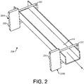
- the cable tray assembly 208 includes a cable tray 210 (or run of cable tray) and a leakage current detection system, generally indicated at 214, configured to detect leakage current emitting from the one or more electrical cables 216 (or other electrical conductors) within the cable tray and communicate the same to an operator/technician.
- the cable tray 210 may be a conventional cable tray, such as but not limited to a wire basket-type or ladder-type cable tray.
- the leakage current detection system 214 may be retrofitted on existing cable tray runs 210 after installation of the latter, or components of the leakage detection may be installed on the cable tray(s) before installation.
- the illustrated leakage detection system 214 includes two (or more) leakage detectors generally indicated at 220A, 220B, respectively, spaced apart from one another along a length of the cable tray run 210 in the direction of current flowing through the cables 216 supported by the cable tray run. It is understood that the leakage detection system 214 may include any number of the leakage detectors 220A, 22B, and it is anticipated that in most cases the system will include numerous leakage detectors. Other than location on the cable tray run 210, the leakage detectors 220A, 220b may be identical, and therefore, like components are indicated by the same reference numerals in the drawings.
- Each of the leakage detectors 220A, 220B includes an electrical conductor 225 (e.g., an insulated electro conductor, such as an insulated wire), and a magnetic sensor 230 coupled to the electrical conductor and configured to detect a magnetic field.
- the illustrated electrical conductor 225 may extend around the cable tray 210, such as in a loop, and have a length extending generally transverse to the lengths of the cable tray run 210.
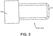
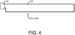
- the length of the electrical conductor 225 or size of the loop may depend on the size of the cable tray 210. For instance, FIG. 3 illustrates a leakage detector for a 6" wide tray, while FIG. 4 illustrates a leakage detector for a 36" wide tray. Other suitable sizes are contemplated.
- the illustrated magnetic sensor 230 comprises a Hall-effect or Hall sensor 250.
- This sensor 250 works based on the Hall-effect principle, which is known to those having ordinary skill in the art. When a conductor or semiconductor with current flowing is introduced perpendicular to a magnetic field, a voltage could be measured at right angles to the current path.
- the Hall-effect sensor 250 provides a proportional voltage to the magnetic flux density applied on the sensor.
- the magnetic sensor 230 may include other electrical components to implement the leakage current detection system 214 and communicate with a central computing device 260. Other types of sensors, other than the Hall-effect sensor, may be used for the magnetic sensor.
- the electrical cables 216 are supported by and within the cable tray run 210.
- Two of the leakage detectors 220A, 220B are coupled to the cable tray and are spaced apart along the length of the cable tray run.
- One of the leakage detectors is considered an incoming or upstream leakage detector 220A, since it detects incoming current I1 flowing into the longitudinal space between the leakage detectors, and the other is considered an outgoing or downstream leakage detector 220B, since it detects outgoing current 12 flowing out of the longitudinal space between the leakage detectors.
- the incoming current I1 at the incoming leakage detector 220A generates a first magnetic flux, which is concentrated by the insulated iron wire 225 of the incoming leakage detector 220A.
- the flux is confined using the first insulated iron wire 225 surrounding the cable tray 210.
- the Hall-effect sensor 250 of the incoming leakage detector 220A senses a parameter (e.g., magnitude) of effective magnetic flux.
- the Hall-effect sensor 220A generates a voltage accordingly with respect to the effective magnetic flux.
- this signal or detection is transmitted to the central computing device 260, such as through a wireless or wired connection.
- the voltage signals from the Hall-effect sensor 250 are amplified and converted to a first DC current via a voltage amplifier and rectifier 270.
- the signal from the Hall-effect sensor 250 also will be in AC current.
- the converted DC signal is passed through an RC circuit 280 for stabilization.
- the stabilized signal from the RC circuit is converted to a digital signal through an Analog-to-Digital Converter (ADC) 280.
- ADC Analog-to-Digital Converter
- the outgoing current I2 at the outgoing leakage detector 220B generates a second magnetic flux, which is concentrated by the insulated iron wire 225 of the outgoing leakage detector.
- the flux is confined using the insulated iron wire 225 of the outgoing leakage detector 220B surrounding the cable tray 210.
- the Hall-effect sensor 250 of the outgoing leakage detector 220B senses a parameter (e.g., magnitude) of effective magnetic flux.
- the Hall-effect sensor 220A generates a voltage accordingly with respect to the effective magnetic flux. Overall, this signal or detection is transmitted to the central computing device 260, such as through a wireless or wired connection.
- the voltage signals from the Hall-effect sensor 250 are amplified and converted to a DC current via a voltage amplifier and rectifier 270. If the electrical cable 216 is carrying AC current, the signal from the Hall-effect sensor 250 also will be in AC current.
- the converted DC signal is passed through an RC circuit 280 for stabilization.
- the stabilized signal from the RC circuit is converted to a digital signal through an Analog-to-Digital Converter (ADC) 280.
- ADC Analog-to-Digital Converter
- This digital signal is transmitted to the central computing device 260 via wireless transmitter 290 (e.g., wireless transceiver), for example.
- wireless transmitter 290 e.g., wireless transceiver
- the central computing device 260 includes readable memory and a processor for executing instructions stored in the readably memory.
- the computing device 260 receives the digital signals from the incoming and outgoing leakage detectors 220A, 220B, respectively, and may receive signals from other leakage detectors where applicable.
- central computing device 260 may include a wireless receiver 295 (e.g., wireless transceiver) for receiving the wireless signals from the leakages sensors 220A, 220B.
- Suitable communication protocols include an LoRA protocol, a Zigbee protocol, or a BLE protocol, among others.
- the processor of the computing device 260 compares the received signals to determine if there is a current leakage in the portion of one or more cables 216 disposed between the two leakage detectors 220A, 220B. If the incoming current I1 is equal to the outgoing current 12, the digital signals will be substantially equal, indicating that there is no leakage of current between the first leakage detector 220A and the second leakage detector 220B. If the incoming current I1 is not equal to the outgoing current 12, the first and second received signals will not be equal, indicating a leakage current 13 in a particular cable tray 210 between the identified first and second detection sensors 220A, 220B.
- the central computing device 260 may generate an alarm signal (e.g., visual and/or auditory alarm 300) to indicate to the technician that leakage current 13 exists.
- the computing device 260 may be configured to provide information to the operator/technician including the location of the leakage and other information pertaining to the leakage.
- the described leakage current detection system is suitable for both AC and DC currents, and does not depend on the direction of the current, but on the magnitude of current entering the longitudinal portion of the cable(s) between the incoming and outgoing leakage detectors.
- the leakage detectors 220A, 220B can be integrated with battery and wireless systems for monitoring. Accuracy can be increased by putting multiple leakage detectors at spaced intervals along the cable tray run.
Landscapes
- Physics & Mathematics (AREA)
- General Physics & Mathematics (AREA)
- Engineering & Computer Science (AREA)
- Architecture (AREA)
- Civil Engineering (AREA)
- Structural Engineering (AREA)
- Testing Of Short-Circuits, Discontinuities, Leakage, Or Incorrect Line Connections (AREA)
- Electromagnetism (AREA)
Abstract
Description
- This application claims the benefit of
U.S. Provisional Patent Application No. 63/157,084, filed March 5, 2021 - The present disclosure generally relates to leakage current detection system for cable trays.
- Electrical wirings (cables) are routed through cable trays from one end to another. At present, if any of wire damage (e.g., wear out insulation) then current leaks out through cable tray. Often, cables are tied and pass through trays. Also these cable trays are mounted at certain height from the ground which makes challenging to physically detect the wire damage.
- In one aspect, a cable tray assembly generally comprises a cable tray run having a length. The cable tray run is configured to support one or more electrical conductors. A first leakage detector is disposed at a first longitudinal location of the cable tray run. The first leakage detector includes a first magnetic sensor. In use the first leakage detector is configured to sense magnetic flux generated by current flowing through the one or more electrical conductors adjacent the first leakage detector. A second leakage detector is disposed at a second longitudinal location of the cable tray run. The second leakage detector includes a second magnetic sensor. In use the second leakage detector is configured to sense magnetic flux generated by current flowing through the one or more electrical conductors adjacent the second leakage detector. The first and second longitudinal locations are spaced apart from one another along the lengths of the cable tray.
- In another aspect, a leakage detection system for use with a cable tray run configured to support one or more electrical cables generally comprises a first leakage detector configured to be disposed at a first longitudinal location of the cable tray run. The first leakage detector including a first magnetic sensor. In use the first leakage detector is configured to sense magnetic flux generated by current flowing through the one or more electrical conductors adjacent the first leakage detector. A second leakage detector is configured to be disposed at a second longitudinal location of the cable tray run. The second leakage detector includes a second magnetic sensor. In use the second leakage detector is configured to sense magnetic flux generated by current flowing through the one or more electrical conductors adjacent the second leakage detector. A central computing device is configured to receive: i) a first signal from the first leakage detector indicative of the magnetic flux generated by current flowing through the one or more electrical conductors adjacent the first leakage detector, and ii) a second signal from the second leakage detector indicative of the magnetic flux generated by current flowing through the one or more electrical conductors adjacent the second leakage detector. The central computing device is configured to compare the first and second signals to determine if there is leakage current from the one or more electrical conductor in the cable tray run.
- In yet another aspect, a leakage detector for use with a cable tray run configured to support one or more electrical cables generally comprises an electrical conductor configured to extend around the cable tray run generally transverse to a length of the cable tray run. A magnetic sensor is coupled to the electrical conductor. In use the second leakage detector is configured to sense magnetic flux generated by current flowing through the one or more electrical conductors adjacent the leakage detector.
- Other objects and features will be in part apparent and in part pointed out herein.
-
-
FIG. 1 is a schematic representation of the cable tray assembly including a leakage current detection system. -
FIG. 2 is a perspective of a cable tray assembly including a leakage detector of a leakage current detection system. -
FIG. 3 is a schematic of a leakage detector including the Hall-effect sensor for a 6" wide tray. -
FIG. 4 is a schematic of a leakage detector including the Hall-effect sensor for a 36" wide tray. -
FIG. 5 is an enlarged, schematic detail of the of a leakage detector. - Electrical distribution systems in factories, residential buildings, and other application typically utilize cable trays to carry over-hanging cables and wall routed cables. Cable trays may also be referred to as cable conduits or cable ducts. Due to environmental factors or overheating, for example, insulation of cables may become weakened such that current begins to leak through the metallic cable trays. Leakage can occur anywhere in the cable system, and cable trays are often mounted at a certain height from the ground, making it challenging to physically detect wire damage. Locating a leakage location is important to shut down a specific area for maintenance and avoid a system wide outage for maintenance. Accurate location of leakage will make repairs quicker and reduce man power effort in identification of the leakage location.
- In general, the present disclosure is directed to a leakage current detection system configured to facilitate identification of a location of leakage current along a cable tray run. The incorporation of the leakage current detection system makes the cable tray "smart," whereby the leakage current detection system can identify the location of the damaged cable and communicate the location to an operator/technician.
- Referring to
FIG. 1 , a cable tray assembly constructed according to the teachings of the present disclosure is generally indicated atreference numeral 208. As described below, thecable tray assembly 208 includes a cable tray 210 (or run of cable tray) and a leakage current detection system, generally indicated at 214, configured to detect leakage current emitting from the one or more electrical cables 216 (or other electrical conductors) within the cable tray and communicate the same to an operator/technician. Thecable tray 210 may be a conventional cable tray, such as but not limited to a wire basket-type or ladder-type cable tray. The leakagecurrent detection system 214 may be retrofitted on existing cable tray runs 210 after installation of the latter, or components of the leakage detection may be installed on the cable tray(s) before installation. - Referring to
FIGS. 1 and2 , the illustratedleakage detection system 214 includes two (or more) leakage detectors generally indicated at 220A, 220B, respectively, spaced apart from one another along a length of thecable tray run 210 in the direction of current flowing through thecables 216 supported by the cable tray run. It is understood that theleakage detection system 214 may include any number of theleakage detectors 220A, 22B, and it is anticipated that in most cases the system will include numerous leakage detectors. Other than location on the cable tray run 210, theleakage detectors 220A, 220b may be identical, and therefore, like components are indicated by the same reference numerals in the drawings. Each of theleakage detectors magnetic sensor 230 coupled to the electrical conductor and configured to detect a magnetic field. As shown inFIG. 2 , the illustratedelectrical conductor 225 may extend around thecable tray 210, such as in a loop, and have a length extending generally transverse to the lengths of the cable tray run 210. As shown inFIGS. 3 and4 , the length of theelectrical conductor 225 or size of the loop may depend on the size of thecable tray 210. For instance,FIG. 3 illustrates a leakage detector for a 6" wide tray, whileFIG. 4 illustrates a leakage detector for a 36" wide tray. Other suitable sizes are contemplated. - Referring to
FIG. 1 , the illustratedmagnetic sensor 230 comprises a Hall-effect orHall sensor 250. Thissensor 250 works based on the Hall-effect principle, which is known to those having ordinary skill in the art. When a conductor or semiconductor with current flowing is introduced perpendicular to a magnetic field, a voltage could be measured at right angles to the current path. The Hall-effect sensor 250 provides a proportional voltage to the magnetic flux density applied on the sensor. As shown inFIG. 1 and described below, themagnetic sensor 230 may include other electrical components to implement the leakagecurrent detection system 214 and communicate with acentral computing device 260. Other types of sensors, other than the Hall-effect sensor, may be used for the magnetic sensor. - Operation of the leakage
current detection system 214 during use is understood best with reference toFIG. 1 . As shown inFIG. 1 , theelectrical cables 216 are supported by and within thecable tray run 210. Two of theleakage detectors upstream leakage detector 220A, since it detects incoming current I1 flowing into the longitudinal space between the leakage detectors, and the other is considered an outgoing ordownstream leakage detector 220B, since it detects outgoing current 12 flowing out of the longitudinal space between the leakage detectors. - The incoming current I1 at the
incoming leakage detector 220A generates a first magnetic flux, which is concentrated by theinsulated iron wire 225 of theincoming leakage detector 220A. The flux is confined using the firstinsulated iron wire 225 surrounding thecable tray 210. The Hall-effect sensor 250 of theincoming leakage detector 220A senses a parameter (e.g., magnitude) of effective magnetic flux. In particular, the Hall-effect sensor 220A generates a voltage accordingly with respect to the effective magnetic flux. Overall, this signal or detection is transmitted to thecentral computing device 260, such as through a wireless or wired connection. In one example, the voltage signals from the Hall-effect sensor 250 are amplified and converted to a first DC current via a voltage amplifier andrectifier 270. If theelectrical cable 216 is carrying AC current, the signal from the Hall-effect sensor 250 also will be in AC current. The converted DC signal is passed through anRC circuit 280 for stabilization. The stabilized signal from the RC circuit is converted to a digital signal through an Analog-to-Digital Converter (ADC) 280. This digital signal is transmitted to thecentral computing device 260 via wireless transmitter 290 (e.g., wireless transceiver), for example. - Similarly, the outgoing current I2 at the
outgoing leakage detector 220B generates a second magnetic flux, which is concentrated by theinsulated iron wire 225 of the outgoing leakage detector. The flux is confined using theinsulated iron wire 225 of theoutgoing leakage detector 220B surrounding thecable tray 210. The Hall-effect sensor 250 of theoutgoing leakage detector 220B senses a parameter (e.g., magnitude) of effective magnetic flux. In particular, the Hall-effect sensor 220A generates a voltage accordingly with respect to the effective magnetic flux. Overall, this signal or detection is transmitted to thecentral computing device 260, such as through a wireless or wired connection. In one example, the voltage signals from the Hall-effect sensor 250 are amplified and converted to a DC current via a voltage amplifier andrectifier 270. If theelectrical cable 216 is carrying AC current, the signal from the Hall-effect sensor 250 also will be in AC current. The converted DC signal is passed through anRC circuit 280 for stabilization. The stabilized signal from the RC circuit is converted to a digital signal through an Analog-to-Digital Converter (ADC) 280. This digital signal is transmitted to thecentral computing device 260 via wireless transmitter 290 (e.g., wireless transceiver), for example. Overall, the structure and operation of the first and secondleakage detection sensors - The
central computing device 260 includes readable memory and a processor for executing instructions stored in the readably memory. Thecomputing device 260 receives the digital signals from the incoming andoutgoing leakage detectors central computing device 260 may include a wireless receiver 295 (e.g., wireless transceiver) for receiving the wireless signals from theleakages sensors computing device 260 compares the received signals to determine if there is a current leakage in the portion of one ormore cables 216 disposed between the twoleakage detectors first leakage detector 220A and thesecond leakage detector 220B. If the incoming current I1 is not equal to the outgoing current 12, the first and second received signals will not be equal, indicating a leakage current 13 in aparticular cable tray 210 between the identified first andsecond detection sensors second leakage detectors central computing device 260 may generate an alarm signal (e.g., visual and/or auditory alarm 300) to indicate to the technician that leakage current 13 exists. Thecomputing device 260 may be configured to provide information to the operator/technician including the location of the leakage and other information pertaining to the leakage. - The described leakage current detection system is suitable for both AC and DC currents, and does not depend on the direction of the current, but on the magnitude of current entering the longitudinal portion of the cable(s) between the incoming and outgoing leakage detectors. The
leakage detectors
Claims (15)
- A cable tray assembly comprising:a cable tray run having a length, wherein the cable tray run is configured to support one or more electrical conductors;a first leakage detector disposed at a first longitudinal location of the cable tray run, the first leakage detector including a first magnetic sensor, wherein in use the first leakage detector is configured to sense magnetic flux generated by current flowing through the one or more electrical conductors adjacent the first leakage detector; anda second leakage detector disposed at a second longitudinal location of the cable tray run, the second leakage detector including a second magnetic sensor, wherein in use the second leakage detector is configured to sense magnetic flux generated by current flowing through the one or more electrical conductors adjacent the second leakage detector,wherein the first and second longitudinal locations are spaced apart from one another along the lengths of the cable tray.
- The cable tray assembly set forth in claim 1, wherein each of the first and second magnetic sensors comprises a Hall-effect sensor.
- The cable tray assembly set forth in claim 1, wherein the first leakage detector further includes a first electrical conductor coupled to the first magnetic sensor, wherein the second leakage detector further includes a second electrical conductor coupled to the second magnetic sensor.
- The cable tray assembly set forth in claim 3, wherein each of the first and second electrical conductors extends generally transverse to the length of the cable tray run
, and optionally, wherein each of the first and second electrical conductors extends generally in a loop around the cable tray run. - The cable tray assembly set forth in claim 4, wherein longitudinal ends of the first and second electrical conductors are coupled to the corresponding one of the first and second magnetic sensors.
- The cable tray assembly set forth in claim 1, further comprising a central computing device configured to receive: i) a first signal from the first leakage detector indicative of the magnetic flux generated by current flowing through the one or more electrical conductors adjacent the first leakage detector, and ii) a second signal from the second leakage detector indicative of the magnetic flux generated by current flowing through the one or more electrical conductors adjacent the second leakage detector, wherein the central computing device is configured to compare the first and second signals to determine if there is leakage current from the one or more electrical conductor in the cable tray run.
- The cable tray assembly set forth in claim 6, wherein the central computing device is configured to determine there is leakage current if the magnetic flux indicated by the first signal and the magnetic flux indicated by the second signal are not substantially equal to one another.
- The cable tray assembly set forth in claim 6, further comprising an alarm in communication with the central computing device, wherein the central computing device is configured to activate the alarm if the central computing device determines there is leakage current from the one or more electrical conductor in the cable tray run.
- The cable tray assembly set forth in claim 1, further comprising a third leakage detector disposed at a third longitudinal location of the cable tray run, the third leakage detector including a third magnetic sensor, wherein in use the third leakage detector is configured to sense magnetic flux generated by current flowing through the one or more electrical conductors adjacent the third leakage detector,
wherein the third longitudinal location is spaced apart from the first and second longitudinal locations along the lengths of the cable tray. - The cable tray assembly set forth in claim 1, further comprising the one or more electrical conductors received in the cable tray run.
- A leakage detection system for use with a cable tray run configured to support one or more electrical cables, comprising:a first leakage detector configured to be disposed at a first longitudinal location of the cable tray run, the first leakage detector including a first magnetic sensor, wherein in use the first leakage detector is configured to sense magnetic flux generated by current flowing through the one or more electrical conductors adjacent the first leakage detector;a second leakage detector configured to be disposed at a second longitudinal location of the cable tray run, the second leakage detector including a second magnetic sensor, wherein in use the second leakage detector is configured to sense magnetic flux generated by current flowing through the one or more electrical conductors adjacent the second leakage detector; anda central computing device configured to receive: i) a first signal from the first leakage detector indicative of the magnetic flux generated by current flowing through the one or more electrical conductors adjacent the first leakage detector, and ii) a second signal from the second leakage detector indicative of the magnetic flux generated by current flowing through the one or more electrical conductors adjacent the second leakage detector, wherein the central computing device is configured to compare the first and second signals to determine if there is leakage current from the one or more electrical conductor in the cable tray run.
- The leakage detection system set forth in claim 11, wherein the central computing device is configured to determine there is leakage current if the magnetic flux indicated by the first signal and the magnetic flux indicated by the second signal are not substantially equal to one another.
- The leakage detection system set forth in claim 11, further comprising an alarm in communication with the central computing device, wherein the central computing device is configured to activate the alarm if the central computing device determines there is leakage current from the one or more electrical conductor in the cable tray run.
- A leakage detector for use with a cable tray run configured to support one or more electrical cables, comprising:an electrical conductor configured to extend around the cable tray run generally transverse to a length of the cable tray run; anda magnetic sensor coupled to the electrical conductor,wherein in use the leakage detector is configured to sense magnetic flux generated by current flowing through the one or more electrical conductors adjacent the leakage detector.
- The leakage detector set forth in claim 14, wherein the magnetic sensor is a Hall-effect sensor.
Applications Claiming Priority (1)
| Application Number | Priority Date | Filing Date | Title |
|---|---|---|---|
| US202163157084P | 2021-03-05 | 2021-03-05 |
Publications (2)
| Publication Number | Publication Date |
|---|---|
| EP4053575A1 true EP4053575A1 (en) | 2022-09-07 |
| EP4053575B1 EP4053575B1 (en) | 2025-12-31 |
Family
ID=80629012
Family Applications (1)
| Application Number | Title | Priority Date | Filing Date |
|---|---|---|---|
| EP22160289.9A Active EP4053575B1 (en) | 2021-03-05 | 2022-03-04 | Leakage current detection in a cable tray |
Country Status (5)
| Country | Link |
|---|---|
| US (1) | US11914000B2 (en) |
| EP (1) | EP4053575B1 (en) |
| CN (1) | CN115015799B (en) |
| CA (1) | CA3151025A1 (en) |
| ES (1) | ES3060522T3 (en) |
Families Citing this family (1)
| Publication number | Priority date | Publication date | Assignee | Title |
|---|---|---|---|---|
| GB2701676A (en) * | 2024-10-23 | 2026-05-06 | Siemens Energy AS | System and method for determining the condition of a subsea circuit |
Citations (3)
| Publication number | Priority date | Publication date | Assignee | Title |
|---|---|---|---|---|
| US20120215469A1 (en) * | 2009-10-28 | 2012-08-23 | Techimp Technologies S.R.L. | Instrument and method for measuring the loss factor of an electrical apparatus |
| US20140009146A1 (en) * | 2012-07-06 | 2014-01-09 | Senis Ag | Current Transducer For Measuring An Electrical Current |
| CN212486021U (en) * | 2020-06-16 | 2021-02-05 | 无锡纵驰电气科技有限公司 | Cable bridge hanger |
Family Cites Families (22)
| Publication number | Priority date | Publication date | Assignee | Title |
|---|---|---|---|---|
| US4059798A (en) * | 1976-03-08 | 1977-11-22 | F. W. Bell, Inc. | Method and apparatus for measuring the current flowing in a workpiece |
| CA2291939C (en) * | 1999-12-08 | 2008-12-30 | Harry E. Orton | Method for diagnosing degradation in aircraft wiring |
| US6833713B2 (en) * | 2003-01-31 | 2004-12-21 | Delphi Technologies, Inc. | Smart wire harness for an electrical circuit |
| US7298132B2 (en) * | 2005-04-13 | 2007-11-20 | Crane Co. | Current sensor |
| JP4544087B2 (en) * | 2005-08-01 | 2010-09-15 | 株式会社デンソー | Current sensor mounting structure |
| US7714567B2 (en) * | 2008-06-22 | 2010-05-11 | Heger Research Llc | Power cable magnetic field sensor |
| CN102004203A (en) | 2009-08-31 | 2011-04-06 | 西门子公司 | Leakage current detection device |
| US20110260735A1 (en) * | 2010-04-22 | 2011-10-27 | Mccabe Paul P | Method for detecting battery cable deterioration in an industrial vehicle |
| US9297864B2 (en) * | 2010-05-19 | 2016-03-29 | Power Distribution, Inc. | Current metering and abnormal event monitoring system |
| CN102361317B (en) | 2011-08-17 | 2013-01-23 | 佛山市中格威电子有限公司 | Leakage protection test circuit |
| KR20130057176A (en) * | 2011-11-23 | 2013-05-31 | 손재우 | Display device judging an electric current and an electric current leakage for cable and cable tray |
| EP2632010B1 (en) | 2012-02-27 | 2015-02-25 | Atreus Enterprises Limited | Leakage current detector for AC and DC systems |
| CN203275565U (en) * | 2013-06-09 | 2013-11-06 | 山西昆明烟草有限责任公司 | Multifunctional grounding detector |
| KR101595658B1 (en) | 2014-07-28 | 2016-02-19 | 공주대학교 산학협력단 | Apparatus and method for detecting residual current |
| RU2578726C1 (en) * | 2014-10-29 | 2016-03-27 | Рустэм Газизович Хузяшев | Method of determining phase voltage, surface resistance and leak current for linear suspended insulator of overhead transmission line and device therefor |
| CN105759102A (en) * | 2016-02-23 | 2016-07-13 | 南京中旭电子科技有限公司 | Hall current sensor employing wireless signal output |
| US10203363B2 (en) * | 2016-12-14 | 2019-02-12 | General Electric Company | DC leakage current detector and method of operation thereof for leakage current detection in DC power circuits |
| US10910825B2 (en) * | 2018-03-21 | 2021-02-02 | Eaton Intelligent Power Limited | Input impedance management and leakage current detection |
| CN108548993A (en) | 2018-06-08 | 2018-09-18 | 中国人民解放军海军工程设计研究院 | A kind of more cable parallel connection interlinkage fault-line selecting methods |
| CN109085448A (en) * | 2018-07-31 | 2018-12-25 | 中国南方电网有限责任公司超高压输电公司检修试验中心 | A kind of converter station equipment leakage current waveform measurement and composition analysis device |
| KR102043700B1 (en) * | 2019-04-30 | 2019-11-13 | 김경현 | Underground line connecting device to safety function leakage of warning |
| CN211530656U (en) * | 2020-04-23 | 2020-09-18 | 中铁建设集团中南建设有限公司 | A bridge with leakage alarm and shrinkable cover |
-
2022
- 2022-03-03 CA CA3151025A patent/CA3151025A1/en active Pending
- 2022-03-04 US US17/686,866 patent/US11914000B2/en active Active
- 2022-03-04 ES ES22160289T patent/ES3060522T3/en active Active
- 2022-03-04 CN CN202210208753.6A patent/CN115015799B/en active Active
- 2022-03-04 EP EP22160289.9A patent/EP4053575B1/en active Active
Patent Citations (3)
| Publication number | Priority date | Publication date | Assignee | Title |
|---|---|---|---|---|
| US20120215469A1 (en) * | 2009-10-28 | 2012-08-23 | Techimp Technologies S.R.L. | Instrument and method for measuring the loss factor of an electrical apparatus |
| US20140009146A1 (en) * | 2012-07-06 | 2014-01-09 | Senis Ag | Current Transducer For Measuring An Electrical Current |
| CN212486021U (en) * | 2020-06-16 | 2021-02-05 | 无锡纵驰电气科技有限公司 | Cable bridge hanger |
Also Published As
| Publication number | Publication date |
|---|---|
| US20220283214A1 (en) | 2022-09-08 |
| CN115015799B (en) | 2026-04-14 |
| US11914000B2 (en) | 2024-02-27 |
| CA3151025A1 (en) | 2022-09-05 |
| CN115015799A (en) | 2022-09-06 |
| ES3060522T3 (en) | 2026-03-26 |
| EP4053575B1 (en) | 2025-12-31 |
Similar Documents
| Publication | Publication Date | Title |
|---|---|---|
| US5250894A (en) | Current sensing system having electronic compensation circuits for conditioning the outputs of current sensors | |
| US11914000B2 (en) | Leakage current detection in cable tray | |
| CN112154585A (en) | Method and device for detecting turn-to-turn short circuits in windings arranged in parallel | |
| US12123782B2 (en) | Wireless sensor | |
| KR102350387B1 (en) | Apparatus and method for detecting fault line | |
| JP6327411B1 (en) | Ground fault location system, ground fault location method | |
| EP1599738B1 (en) | Detection of earth faults in three phase systems | |
| KR100592845B1 (en) | Overhead line lightning strike and accident point detection device | |
| JPH10170589A (en) | Substation premises fault point location device | |
| US10324140B2 (en) | Zero sequence sensing apparatus and method | |
| ES2820589T3 (en) | Procedure and apparatus for locating current detectors | |
| US20250341547A1 (en) | Residual current operated device with all-current sensitive detection of differential currents and charging plug, in-cable control box, charging cable and charger therewith | |
| KR102593739B1 (en) | junction box for wireless power track of detecting wire disconnection | |
| US20170269127A1 (en) | Electrical measurement apparatus having a detector providing an identification signal and corresponding method | |
| JP5377170B2 (en) | Ground fault detector for DC electric railway | |
| KR20090039134A (en) | Power line monitoring system using WSS-based sensor tag and its method | |
| KR102072360B1 (en) | Device measuring the force of electronic attraction on two-bundle conductor of overhead transmission line | |
| FI100828B (en) | Measuring device for measuring the current in overhead lines of a medium voltage line | |
| KR102880206B1 (en) | Power remote management module and power remote management system having the same | |
| JPH08103022A (en) | Monitoring equipment for power systems and electrical equipment | |
| JP3232520U (en) | Current detection sensor and ground fault identification system | |
| KR102287298B1 (en) | Method for detecting leakage current through ground wire between electric poles and system for the same | |
| JP4590983B2 (en) | Load capacity detector for wiring duct | |
| JP2006050696A (en) | Underground accident section determination device | |
| KR20170001884A (en) | Detecting method and a device for degradation of electric wire insulation |
Legal Events
| Date | Code | Title | Description |
|---|---|---|---|
| PUAI | Public reference made under article 153(3) epc to a published international application that has entered the european phase |
Free format text: ORIGINAL CODE: 0009012 |
|
| STAA | Information on the status of an ep patent application or granted ep patent |
Free format text: STATUS: THE APPLICATION HAS BEEN PUBLISHED |
|
| AK | Designated contracting states |
Kind code of ref document: A1 Designated state(s): AL AT BE BG CH CY CZ DE DK EE ES FI FR GB GR HR HU IE IS IT LI LT LU LV MC MK MT NL NO PL PT RO RS SE SI SK SM TR |
|
| STAA | Information on the status of an ep patent application or granted ep patent |
Free format text: STATUS: REQUEST FOR EXAMINATION WAS MADE |
|
| 17P | Request for examination filed |
Effective date: 20230307 |
|
| RBV | Designated contracting states (corrected) |
Designated state(s): AL AT BE BG CH CY CZ DE DK EE ES FI FR GB GR HR HU IE IS IT LI LT LU LV MC MK MT NL NO PL PT RO RS SE SI SK SM TR |
|
| P01 | Opt-out of the competence of the unified patent court (upc) registered |
Effective date: 20230521 |
|
| STAA | Information on the status of an ep patent application or granted ep patent |
Free format text: STATUS: EXAMINATION IS IN PROGRESS |
|
| 17Q | First examination report despatched |
Effective date: 20240326 |
|
| GRAP | Despatch of communication of intention to grant a patent |
Free format text: ORIGINAL CODE: EPIDOSNIGR1 |
|
| STAA | Information on the status of an ep patent application or granted ep patent |
Free format text: STATUS: GRANT OF PATENT IS INTENDED |
|
| RIC1 | Information provided on ipc code assigned before grant |
Ipc: G01R 31/52 20200101AFI20250707BHEP Ipc: G01R 31/58 20200101ALI20250707BHEP Ipc: G01R 15/20 20060101ALI20250707BHEP Ipc: G01R 31/08 20200101ALI20250707BHEP |
|
| INTG | Intention to grant announced |
Effective date: 20250721 |
|
| GRAS | Grant fee paid |
Free format text: ORIGINAL CODE: EPIDOSNIGR3 |
|
| GRAA | (expected) grant |
Free format text: ORIGINAL CODE: 0009210 |
|
| STAA | Information on the status of an ep patent application or granted ep patent |
Free format text: STATUS: THE PATENT HAS BEEN GRANTED |
|
| AK | Designated contracting states |
Kind code of ref document: B1 Designated state(s): AL AT BE BG CH CY CZ DE DK EE ES FI FR GB GR HR HU IE IS IT LI LT LU LV MC MK MT NL NO PL PT RO RS SE SI SK SM TR |
|
| REG | Reference to a national code |
Ref country code: CH Ref legal event code: F10 Free format text: ST27 STATUS EVENT CODE: U-0-0-F10-F00 (AS PROVIDED BY THE NATIONAL OFFICE) Effective date: 20251231 Ref country code: GB Ref legal event code: FG4D |
|
| REG | Reference to a national code |
Ref country code: DE Ref legal event code: R096 Ref document number: 602022027698 Country of ref document: DE |
|
| REG | Reference to a national code |
Ref country code: IE Ref legal event code: FG4D |
|
| REG | Reference to a national code |
Ref country code: ES Ref legal event code: FG2A Ref document number: 3060522 Country of ref document: ES Kind code of ref document: T3 Effective date: 20260326 |
|
| PGFP | Annual fee paid to national office [announced via postgrant information from national office to epo] |
Ref country code: GB Payment date: 20260219 Year of fee payment: 5 |
|
| REG | Reference to a national code |
Ref country code: LT Ref legal event code: MG9D |
|
| PGFP | Annual fee paid to national office [announced via postgrant information from national office to epo] |
Ref country code: NO Payment date: 20260223 Year of fee payment: 5 Ref country code: DE Payment date: 20260219 Year of fee payment: 5 |
|
| PG25 | Lapsed in a contracting state [announced via postgrant information from national office to epo] |
Ref country code: HR Free format text: LAPSE BECAUSE OF FAILURE TO SUBMIT A TRANSLATION OF THE DESCRIPTION OR TO PAY THE FEE WITHIN THE PRESCRIBED TIME-LIMIT Effective date: 20251231 Ref country code: FI Free format text: LAPSE BECAUSE OF FAILURE TO SUBMIT A TRANSLATION OF THE DESCRIPTION OR TO PAY THE FEE WITHIN THE PRESCRIBED TIME-LIMIT Effective date: 20251231 |
|
| PGFP | Annual fee paid to national office [announced via postgrant information from national office to epo] |
Ref country code: AT Payment date: 20260301 Year of fee payment: 5 |
|
| PGFP | Annual fee paid to national office [announced via postgrant information from national office to epo] |
Ref country code: BE Payment date: 20260219 Year of fee payment: 5 Ref country code: IT Payment date: 20260219 Year of fee payment: 5 |
|
| PG25 | Lapsed in a contracting state [announced via postgrant information from national office to epo] |
Ref country code: RS Free format text: LAPSE BECAUSE OF FAILURE TO SUBMIT A TRANSLATION OF THE DESCRIPTION OR TO PAY THE FEE WITHIN THE PRESCRIBED TIME-LIMIT Effective date: 20260331 |
|
| PGFP | Annual fee paid to national office [announced via postgrant information from national office to epo] |
Ref country code: FR Payment date: 20260219 Year of fee payment: 5 |
|
| PG25 | Lapsed in a contracting state [announced via postgrant information from national office to epo] |
Ref country code: LV Free format text: LAPSE BECAUSE OF FAILURE TO SUBMIT A TRANSLATION OF THE DESCRIPTION OR TO PAY THE FEE WITHIN THE PRESCRIBED TIME-LIMIT Effective date: 20251231 |
|
| PG25 | Lapsed in a contracting state [announced via postgrant information from national office to epo] |
Ref country code: BG Free format text: LAPSE BECAUSE OF FAILURE TO SUBMIT A TRANSLATION OF THE DESCRIPTION OR TO PAY THE FEE WITHIN THE PRESCRIBED TIME-LIMIT Effective date: 20251231 |
|
| REG | Reference to a national code |
Ref country code: NL Ref legal event code: MP Effective date: 20251231 |
|
| REG | Reference to a national code |
Ref country code: AT Ref legal event code: MK05 Ref document number: 1873854 Country of ref document: AT Kind code of ref document: T Effective date: 20251231 |
|
| PG25 | Lapsed in a contracting state [announced via postgrant information from national office to epo] |
Ref country code: NL Free format text: LAPSE BECAUSE OF FAILURE TO SUBMIT A TRANSLATION OF THE DESCRIPTION OR TO PAY THE FEE WITHIN THE PRESCRIBED TIME-LIMIT Effective date: 20251231 |
|
| PG25 | Lapsed in a contracting state [announced via postgrant information from national office to epo] |
Ref country code: LT Free format text: LAPSE BECAUSE OF FAILURE TO SUBMIT A TRANSLATION OF THE DESCRIPTION OR TO PAY THE FEE WITHIN THE PRESCRIBED TIME-LIMIT Effective date: 20251231 |
|
| PG25 | Lapsed in a contracting state [announced via postgrant information from national office to epo] |
Ref country code: SM Free format text: LAPSE BECAUSE OF FAILURE TO SUBMIT A TRANSLATION OF THE DESCRIPTION OR TO PAY THE FEE WITHIN THE PRESCRIBED TIME-LIMIT Effective date: 20251231 |
|
| PGFP | Annual fee paid to national office [announced via postgrant information from national office to epo] |
Ref country code: ES Payment date: 20260401 Year of fee payment: 5 |
|
| PG25 | Lapsed in a contracting state [announced via postgrant information from national office to epo] |
Ref country code: PL Free format text: LAPSE BECAUSE OF FAILURE TO SUBMIT A TRANSLATION OF THE DESCRIPTION OR TO PAY THE FEE WITHIN THE PRESCRIBED TIME-LIMIT Effective date: 20251231 |
|
| PG25 | Lapsed in a contracting state [announced via postgrant information from national office to epo] |
Ref country code: AT Free format text: LAPSE BECAUSE OF FAILURE TO SUBMIT A TRANSLATION OF THE DESCRIPTION OR TO PAY THE FEE WITHIN THE PRESCRIBED TIME-LIMIT Effective date: 20251231 |
|
| PG25 | Lapsed in a contracting state [announced via postgrant information from national office to epo] |
Ref country code: EE Free format text: LAPSE BECAUSE OF FAILURE TO SUBMIT A TRANSLATION OF THE DESCRIPTION OR TO PAY THE FEE WITHIN THE PRESCRIBED TIME-LIMIT Effective date: 20251231 |
|
| PG25 | Lapsed in a contracting state [announced via postgrant information from national office to epo] |
Ref country code: PT Free format text: LAPSE BECAUSE OF FAILURE TO SUBMIT A TRANSLATION OF THE DESCRIPTION OR TO PAY THE FEE WITHIN THE PRESCRIBED TIME-LIMIT Effective date: 20260430 Ref country code: IS Free format text: LAPSE BECAUSE OF FAILURE TO SUBMIT A TRANSLATION OF THE DESCRIPTION OR TO PAY THE FEE WITHIN THE PRESCRIBED TIME-LIMIT Effective date: 20260430 |
|
| PG25 | Lapsed in a contracting state [announced via postgrant information from national office to epo] |
Ref country code: CZ Free format text: LAPSE BECAUSE OF FAILURE TO SUBMIT A TRANSLATION OF THE DESCRIPTION OR TO PAY THE FEE WITHIN THE PRESCRIBED TIME-LIMIT Effective date: 20251231 |
|
| PG25 | Lapsed in a contracting state [announced via postgrant information from national office to epo] |
Ref country code: SK Free format text: LAPSE BECAUSE OF FAILURE TO SUBMIT A TRANSLATION OF THE DESCRIPTION OR TO PAY THE FEE WITHIN THE PRESCRIBED TIME-LIMIT Effective date: 20251231 |
|
| PG25 | Lapsed in a contracting state [announced via postgrant information from national office to epo] |
Ref country code: SE Free format text: LAPSE BECAUSE OF FAILURE TO SUBMIT A TRANSLATION OF THE DESCRIPTION OR TO PAY THE FEE WITHIN THE PRESCRIBED TIME-LIMIT Effective date: 20251231 |