EP4053503B1 - Angular rate sensor based on frequency modulation and drive strategy for same - Google Patents
Angular rate sensor based on frequency modulation and drive strategy for same Download PDFInfo
- Publication number
- EP4053503B1 EP4053503B1 EP22159181.1A EP22159181A EP4053503B1 EP 4053503 B1 EP4053503 B1 EP 4053503B1 EP 22159181 A EP22159181 A EP 22159181A EP 4053503 B1 EP4053503 B1 EP 4053503B1
- Authority
- EP
- European Patent Office
- Prior art keywords
- drive
- proof masses
- proof
- substrate
- axis
- Prior art date
- Legal status (The legal status is an assumption and is not a legal conclusion. Google has not performed a legal analysis and makes no representation as to the accuracy of the status listed.)
- Active
Links
Images


Classifications
-
- G—PHYSICS
- G01—MEASURING; TESTING
- G01C—MEASURING DISTANCES, LEVELS OR BEARINGS; SURVEYING; NAVIGATION; GYROSCOPIC INSTRUMENTS; PHOTOGRAMMETRY OR VIDEOGRAMMETRY
- G01C19/00—Gyroscopes; Turn-sensitive devices using vibrating masses; Turn-sensitive devices without moving masses; Measuring angular rate using gyroscopic effects
- G01C19/56—Turn-sensitive devices using vibrating masses, e.g. vibratory angular rate sensors based on Coriolis forces
- G01C19/5719—Turn-sensitive devices using vibrating masses, e.g. vibratory angular rate sensors based on Coriolis forces using planar vibrating masses driven in a translation vibration along an axis
- G01C19/5733—Structural details or topology
- G01C19/574—Structural details or topology the devices having two sensing masses in anti-phase motion
- G01C19/5747—Structural details or topology the devices having two sensing masses in anti-phase motion each sensing mass being connected to a driving mass, e.g. driving frames
-
- G—PHYSICS
- G01—MEASURING; TESTING
- G01C—MEASURING DISTANCES, LEVELS OR BEARINGS; SURVEYING; NAVIGATION; GYROSCOPIC INSTRUMENTS; PHOTOGRAMMETRY OR VIDEOGRAMMETRY
- G01C19/00—Gyroscopes; Turn-sensitive devices using vibrating masses; Turn-sensitive devices without moving masses; Measuring angular rate using gyroscopic effects
- G01C19/56—Turn-sensitive devices using vibrating masses, e.g. vibratory angular rate sensors based on Coriolis forces
- G01C19/5705—Turn-sensitive devices using vibrating masses, e.g. vibratory angular rate sensors based on Coriolis forces using masses driven in reciprocating rotary motion about an axis
- G01C19/5712—Turn-sensitive devices using vibrating masses, e.g. vibratory angular rate sensors based on Coriolis forces using masses driven in reciprocating rotary motion about an axis the devices involving a micromechanical structure
-
- G—PHYSICS
- G01—MEASURING; TESTING
- G01C—MEASURING DISTANCES, LEVELS OR BEARINGS; SURVEYING; NAVIGATION; GYROSCOPIC INSTRUMENTS; PHOTOGRAMMETRY OR VIDEOGRAMMETRY
- G01C19/00—Gyroscopes; Turn-sensitive devices using vibrating masses; Turn-sensitive devices without moving masses; Measuring angular rate using gyroscopic effects
- G01C19/56—Turn-sensitive devices using vibrating masses, e.g. vibratory angular rate sensors based on Coriolis forces
Definitions
- the present invention relates generally to microelectromechanical systems (MEMS) devices. More specifically, the present invention relates to a MEMS angular rate sensor device based on frequency modulation and a drive strategy for the angular rate sensor.
- MEMS microelectromechanical systems
- An angular rate sensor also referred to as a gyroscope, senses angular speed, rate, or velocity, also referred to as angular rate of rotation, around one or more axes.
- angular rate sensors are microelectromechanical systems (MEMS) devices manufactured using MEMS technology, which provides a way to make very small mechanical structures and integrate these structures with electrical devices on a single substrate using conventional batch semiconductor processing techniques.
- MEMS angular rate sensors are widely used in applications such as automotive, inertial guidance systems, gaming systems, smartphones, cameras, etc.
- MEMS gyroscopes operate on the basis of two differing principles: amplitude modulation and frequency modulation.
- Conventional amplitude modulated gyroscopes detect angular rates by demodulating the force applied to a movable sense mass from Coriolis accelerations as a result of the sense mass velocity provided from the driven frequency and amplitude.
- the sense mass motion is in a direction perpendicular to the drive direction and perpendicular to the angular rate vector.
- Amplitude modulated gyroscopes can place high demands on the sense detection as the Coriolis forces are small.
- the quadrature signal induced from manufacturing imperfections can be hundreds of times larger than the signal to be detected.
- a frequency modulated (FM) gyroscope operates by driving the movable sense mass in two drive directions, creating a circular orbit that will undergo a change in oscillation frequency if subjected to an angular velocity that is perpendicular to both driven directions.
- FM gyroscopes are disclosed in the documents EP 3312559 A1 , US 2016/003618 A1 and in the article " Quadrature FM gyroscope" by Mitchell H Kline et al.
- an angular rate sensor comprising: first and second proof masses spaced apart from a surface of a substrate, the first and second proof masses being configured to move along a first axis and a second axis, the first axis being perpendicular to the surface of the substrate and the second axis being parallel to the surface of the substrate; first drive systems; and second drive systems, one each of the first and second drive systems being interconnected with one each of the first and second proof masses, wherein the first and second drive systems are configured to enable drive motion of the first and second proof masses along both of the first and second axes in an orbital drive direction at a drive frequency, the second proof mass being driven out-of-phase relative to the first proof mass.
- the angular rate sensor is sensitive to angular velocity about a third axis oriented parallel to the surface of the substrate and perpendicular to the second axis; and the drive frequency of the drive motion of the first and second proof masses is configured to change in response to the angular velocity of the angular rate sensor about the third axis.
- each of the first drive systems comprises a first drive portion and a second drive portion, the first drive portion including a first anchor coupled to the surface of the substrate, a first paddle structure interposed between and elastically coupled to each of the first anchor and one of the first and second proof masses, and a first electrode formed on the surface of the substrate underlying the first paddle structure
- the second drive portion including a second anchor coupled to the surface of the substrate, a second paddle structure interposed between and elastically coupled to each of the second anchor and the one of the first and second proof masses, and a second electrode formed on the surface of the substrate underlying the second paddle structure, wherein the first and second paddle structures and the corresponding first and second electrodes form first parallel-plate capacitive drive elements for enabling motion of the one of the first and second proof masses along the first axis perpendicular to the surface of the substrate; and each of the second drive systems comprises first and second anchors coupled to the surface of the substrate, a frame
- the first drive portion further may comprise a third electrode formed on the surface of the substrate underlying the first paddle structure; and the second drive portion further comprise a fourth electrode formed on the surface of the substrate underlying the second paddle structure, the third and fourth electrodes being positioned closer to the pivot axis than the first and second electrodes, and the first and second paddle structures and the corresponding third and fourth electrodes forming first parallel-plate capacitive sense elements for sensing the motion of the one of the first and second proof masses along the first axis.
- Each of the second drive systems may further comprise: second electrodes surrounded by the frame to form parallel-plate capacitive sense elements for sensing the motion of the one of the first and second proof masses along the second axis; and a pivot anchor structure coupled to the surface of the substrate and centrally located within the frame such that a first portion of the frame is pivotally coupled to the pivot anchor structure and a second portion of the frame is pivotally coupled to the pivot anchor structure, the first and second portions being located on opposing sides of a pivot axis established at the pivot anchor structure, wherein subsets of each of the first and second electrodes are positioned on opposing sides of the pivot axis with the second electrodes being located closer to the pivot axis than the first electrodes.
- Each of the first and second proof masses may include first and second notched regions extending inwardly from opposing exterior sides of the first and second proof masses, one of the first drive systems residing in the first and second notched regions of the first proof mass and another one of the first drive systems residing in the first and second notched regions of the second proof mass.
- One of the second drive systems may be coupled to a first exterior side of the first proof mass and another one of the second drive systems is coupled to a second exterior side of the second proof mass.
- an angular rate sensor according to the first aspect, further comprising third and fourth proof masses spaced apart from the surface of the substrate, one each of the first and second drive systems being interconnected with one each of the third and fourth proof masses, wherein the first and second drive systems interconnected with the third and fourth proof masses are configured to enable drive motion of the third proof mass along both of the first and second axes in the orbital drive direction at the drive frequency, the third proof mass being driven in phase with the first proof mass and the fourth proof mass being driven in phase with the second proof mass.
- a frequency modulated (FM) angular rate sensor includes a drive strategy for controlling drive motion of the angular rate sensor in two directions.
- the drive motion has an in-plane component parallel to a planar surface of the angular rate sensor and a vertical component perpendicular to the planar surface of the angular rate sensor.
- the drive strategy includes a first drive system for providing vertical proof mass actuation force and feedback signals on the angular rate sensor and a second drive system for providing in-plane proof mass actuation force and feedback signals.
- the first drive system implements vertical gap-closing actuation and feedback capacitors for controlling the vertical motion of the proof mass.
- the vertical gap-closing capacitors are configured to be part of structures linked to the proof masses and are not placed on the proof masses themselves.
- the structures pivot on anchored points allowing the proof masses to move vertically in a guided fashion. These structures additionally perform the task of limiting common mode motion of the proof masses to which they are attached.
- the feedback capacitors associated with the first drive system are suitably positioned to reduce nonlinear measurement output.
- the second drive system implements in-plane actuation and feedback capacitors, and includes a pivot structure that mimics that used for the vertical motion, thereby making the capacitance-to-motion of the proof mass transfer functions as similar as possible.
- FIG. 1 shows a top view of an angular rate sensor 20 in accordance with an embodiment.
- Angular rate sensor 20 alternatively referred to as a gyroscope, includes first, second, third, and fourth proof masses 22, 24, 26, 28 spaced apart from a surface 30 of a substrate 32.
- First and second proof masses 22, 24 are laterally adjacent to one another and third and fourth proof masses 26, 28 are laterally adjacent to one another.
- first and fourth proof masses 22, 28 are laterally adjacent to one another and second and third proof masses 24, 26 are laterally adjacent to one another.
- Angular rate sensor 20 further includes first drive systems 34, second drive systems 36, and coupling structures 38.
- First and second proof masses 22, 24 form a two proof mass gyroscope device.
- third and fourth proof masses 26, 28 form a two proof mass gyroscope device.
- first, second, third, and fourth proof masses 22, 24, 26, 28 may be considered a four proof mass gyroscope device.
- a four proof mass gyroscope device is described herein, it should be understood that the following description applies equivalently to a two proof mass gyroscope configuration.
- first and second drive systems 34, 36 is interconnected with one each of the first, second, third, and fourth proof masses 22, 24, 26, 28.
- each of first, second, third, and fourth proof masses 22, 24, 26, 28 includes first and second notched regions 40, 42 extending inwardly from opposing sidewalls 44, 46 of first, second, third, and fourth proof masses 22, 24, 26, 28.
- One of first drive systems 34 resides in first and second notched regions 40, 42 of first proof mass 22.
- others of first drive systems 34 reside in first and second notched regions 40, 42 of corresponding second, third, and fourth proof masses 24, 26, 28.
- One of second drive systems 36 is coupled to first proof mass 22 proximate a first end wall 48 of first proof mass 22.
- second drive systems 36 are coupled to second, third, and fourth proof masses 24, 26, 28 proximate corresponding second, third, and fourth end walls 50, 52, 54 of second, third, and fourth proof masses 24, 26, 28.
- second drive systems 36 are located outside of a boundary circumscribing first, second, third, and fourth proof masses 24, 26, 28, 30.
- One of coupling structures 38 is interposed between and interconnects first and second proof masses 22, 24 and another of coupling structures 38 is interposed between and interconnects third and fourth proof masses 26, 28.
- First, second, third, and fourth proof masses 22, 24, 26, 28 are suspended apart from surface 32 of substrate 30 using various elastic components, rigid components, and anchors, as described herein.
- an elastic component or elastic member generally refers to a resilient component that can spontaneously resume its original or normal shape after being stretched, compressed, or otherwise distorted.
- a stiff component generally refers to a component that is rigid, or non-bending, relative to an elastic member. As such, stiff components are largely non-compliant, and the elastic components are more compliant than the stiff components.
- the elastic and stiff components are suspended above the planar surface of the substrate.
- the elastic components may include, by way of example, coupling links, spring structures, springs, flexures, flexible support elements, and the like.
- an anchor is a largely rigid element that is fixed directly to the surface of the substrate and suspends the elastic and stiff components above the planar surface of the substrate.
- the anchors are illustrated in the figures by boxes with a "X" therein.
- a three-dimensional coordinate system is represented in which an X-axis 60 is directed rightward and leftward on the page, a Y-axis 62 is directed upward and downward on the page, and a Z-axis 64 is directed into and out of the page.
- X-axis 60 and Y-axis 62 define an X-Y plane 66, with surface 30 of substrate 32 being oriented substantially parallel to X-Y plane 66 and Z-axis 64 being perpendicular to X-Y plane 66.
- first, second, third, and fourth proof masses 22, 24, 26, 28 are configured to move along Z-axis 64 (e.g., a first axis) perpendicular to surface 30 of substrate 32 and concurrently along X-axis 60 (e.g., a second axis) parallel to surface 30 of substrate 32.
- angular rate sensor 20 is sensitive to angular velocity about Y-axis 62 (e.g., a third axis) parallel to surface 30 of substrate 32.
- FIG. 2 shows a diagram demonstrating an orbital drive direction for proof masses of angular rate sensor 20.
- First and second drive systems 34, 36 interconnected with first proof mass 22 are configured to enable drive motion of first, second, third, and fourth proof masses 22 , 24, 26, 28 along both of X-and Z-axes 60, 64 in an orbital drive direction 68.
- first, second, third, and fourth proof masses 22, 24, 26, 28 are configured for concurrent movement in-plane (along X-axis 60) and out-of-plane (along Z-axis 64) to yield the circular or orbital drive motion in orbital drive direction 68.
- second and fourth proof masses 24, 28 are driven out of phase relative to first and third proof masses 22, 26. That is, second and fourth proof masses 24, 28 may be driven one hundred eighty degrees out of phase (e.g., in anti-phase) relative to first and third proof masses 22, 26. Accordingly, in the illustration of FIG. 2 , at a given instant, first and third proof masses 22, 26 may be closer to surface 32 of substrate 30 than second and fourth proof masses 24, 28.
- first and second drive systems 34, 36 are configured to drive adjacent ones of first, second, third, and fourth proof masses 22, 24, 26, 28 along X-and Z-axes 60, 64 in anti-phase (e.g., 180° out of phase). Further, the configuration of first and second drive systems 34, 36 along with coupling structures 38 enable the anti-phase motion of the adjacent proof masses 22, 24, 26, 28 and effectively constrains (e.g., rejects, limits, or prevents) in-phase (e.g., common mode) motion of the adjacent first, second, third, and fourth proof masses 22, 24, 26, 28 along X- and Z-axes 60, 64.
- An example embodiment of first drive system 34 will be described in detail in connection with FIGs.
- first, second, third, and fourth proof masses 22, 24, 26, 28 will be demonstrated in connection with FIGs. 15 and 16.
- FIG. 3 shows a top view of a portion of angular rate sensor 20 including one of first drive systems 34. More particularly, the example of FIG. 3 shows first drive system 34 residing in first and second notched regions 40, 42 of first proof mass 22. It should be understood that the following discussion of the structural elements of first drive system 34 shown in FIG. 3 applies equivalently to each of first drive systems 34 coupled to each of second, third, and fourth proof masses 24, 26, 28 ( FIG. 1 ).
- first drive system 34 includes a first drive portion 72 and a second drive portion 74 arranged in mirror symmetry relative to an axis of symmetry 76 at a centerline of first proof mass 22.
- First drive portion 72 includes a first anchor 78 coupled to surface 30 ( FIG. 1 ) of substrate 32 ( FIG. 1 ) and a first paddle structure 80 residing in first notched region 40 and elastically coupled to each of first anchor 78 and first proof mass 22.
- First drive portion 72 further includes at least one actuation electrode 82 (shown in dashed line form) and at least one feedback electrode 84 (shown in dashed line form) formed on surface 30 of substrate 32 underlying first paddle structure 80.
- Second drive portion 74 includes a second anchor 88 coupled to surface 30 of substrate 32 and a second paddle structure 90 residing in second notched region 42 and elastically coupled to each of second anchor 88 and first proof mass 22. Second drive portion 74 further includes at least one actuation electrode 92 (shown in dashed line form) and at least one feedback electrode 94 (shown in dashed line form) formed on surface 30 of substrate 32 underlying second paddle structure 90.
- first drive systems 34 of adjacent first and fourth proof masses 22, 28 are connected and first drive systems 34 of the adjacent second and third proof masses 24, 26 are connected.
- second anchor 88 of first drive system 34 coupled to first proof mass 22 additionally functions as first anchor 78 of first drive system 34 coupled to fourth proof mass 28.
- second anchor 88 of first drive system 34 coupled to second proof mass 24 additionally functions as first anchor 78 of first drive system coupled to third proof mass 26.
- the interconnected first drive systems 34 also function as coupling structures for constraining in-phase motion of the adjacent first and fourth proof masses 22, 28 and for constraining in-phase motion of the adjacent second and third proof masses 24, 22 along X- and/or Z-axes 60, 64.
- First paddle structure 80 is interconnected to first anchor 78 via elastic members 96 and to first proof mass 22 via elastic members 98.
- second paddle structure 90 is interconnected to second anchor 88 via elastic members 96 and to first proof mass 22 via elastic members 98.
- Elastic members 96 deform to enable pivotal drive motion of first and second paddle structures 80, 90 about respective first and second pivot axes 100, 102.
- elastic members 98 deform to enable opposite pivotal motion at respective third and fourth pivot axes 104, 106 to effectively move first proof mass 22 in a direction that is opposite to the movement of first and second paddle structures 80, 90 (discussed in greater detail below).
- FIG. 4 shows a representative side view of first drive system 34.
- First paddle structure 80 and actuation electrode 82 form a parallel plate capacitive drive element.
- second paddle structure 90 and actuation electrode 92 form a parallel plate capacitive drive element.
- a change in capacitance, C D between actuation electrodes 82, 92 and respective first and second paddle structures 80, 90 can be used to drive first and second paddle structures 80, 90 and consequently, one of the proof masses (first proof mass 22 shown in dashed line form) along Z-axis 64.
- First paddle structure 80 and feedback electrode 84 form a parallel plate capacitive sense element.
- second paddle structure 90 and feedback electrode 94 form a parallel plate capacitive sense element.
- a change in the sensed capacitance, C M , between feedback electrodes 84, 94 and respective first and second paddle structures 80, 90 can be used to measure, or otherwise detect, the motion of first and second paddle structures 80, 90 and consequently, the motion of one of proof masses 22, 24, 26, 28 along Z-axis 64.
- feedback electrodes 84, 94 are located closer to the corresponding first and second pivot axes 100, 102 than actuation electrodes 82, 92 to reduce nonlinear measurement output.
- Actual capacitors, C D and C M are not present between first and second paddle structures 80, 90 and their respective electrodes 82, 84, 92, 94. Rather, the capacitor symbols shown in FIG. 3 represent the drive and sense signals, which in this example are capacitance changes.
- FIG. 5 shows a representative side view of first drive system 34 demonstrating pivotal motion.
- drive signals between actuation electrodes 82, 92 and the corresponding first and second drive paddles 80, 90 causes opposite pivotal motion at first and second pivot axes 100, 102 (e.g., counterclockwise at first pivot axis 100 and clockwise at second pivot axis 102).
- first and second drive paddles 80, 90 move upwardly in a direction parallel to Z-axis 64 away from surface 32 of substrate 30.
- first proof mass 22 also moves upwardly. Pivoting motion at third and fourth pivot axes 104, 106 enables first proof mass 22 to remain substantially parallel to surface 32 of substrate 30.
- FIG. 6 shows another representative side view of first drive system 34 demonstrating pivotal motion.
- drive signals between actuation electrodes 82, 92 and the corresponding first and second drive paddles 80, 90 causes opposite pivotal motion at first and second pivot axes 100, 102 (e.g., clockwise at first pivot axis 100 and counterclockwise at second pivot axis 102).
- first and second drive paddles 80, 90 move downwardly in a direction parallel to Z-axis 64 toward surface 32 of substrate 30.
- first proof mass 22 also moves downwardly toward surface 32 of substrate 30.
- Pivoting motion at third and fourth pivot axes 104, 106 again enables first proof mass 22 to remain substantially parallel to surface 32 of substrate 30.
- first drive systems 34 enable vertical gap-closing actuation and feedback capacitors for controlling the vertical motion of the proof masses in FM angular rate sensor 20. It should be understood that first drive systems 34 (in the absence of second drive systems 36) may alternatively be implemented for controlling vertical motion of proof masses in an amplitude modulated angular rate sensor.
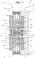
- FIG. 7 shows a top view of angular rate sensor 20 including one of second drive systems 36.
- each of the second drive systems 36 includes first and second anchors 110, 112 coupled to surface 30 of substrate 32.
- a stiff or rigid frame 114 is positioned between and elastically coupled to first and second anchors 110, 112. Further, frame 114 is coupled to one of proof masses 22, 24, 26, 28 ( FIG. 1 ).
- portions of first proof mass 22 and the interconnection of first proof mass 22 with frame 114 of second drive system 36 is represented by dashed line boxes.
- a pivot anchor structure 116 is coupled to surface 30 ( FIG. 1 ) of substrate 32 ( FIG. 1 ) and is centrally located within frame 114 such that a first portion 118 of frame 114 is pivotally coupled to pivot anchor structure 116 and a second portion 120 of frame 114 is pivotally coupled to pivot anchor structure 116.
- actuation electrodes 122 are coupled to surface 30 of substrate 32 and are surrounded by frame 114 to form parallel-plate capacitive drive elements for enabling motion of the attached one of proof masses 22, 24, 26, 28 along X-axis 60 parallel to surface 30 of substrate 32.
- feedback electrodes 124 are coupled to surface 30 of substrate 32 and are surrounded by frame 114 to form parallel-plate capacitive sense elements for sensing the motion of frame 114 and consequently the attached one of proof masses 22, 24, 26, 28 along X-axis 60.
- the motion of second drive system 36 and the corresponding proof mass 22, 24, 26, 28 along X-axis 60 will be discussed in connection with FIGs. 8 and 9 .
- Pivot anchor structure 116 centrally located in frame 114 includes first and second pivot anchors 126, 128 coupled to surface 30 ( FIG. 1 ) of substrate 32 ( FIG. 1 ).
- First portion 118 of frame 114 is interconnected to first pivot anchor 126 via elastic members 130 and is interconnected to one of proof masses 22, 24, 26, 28 via elastic members 132.
- second portion 120 of frame 114 is interconnected to second pivot anchor 128 via elastic members 130 and is interconnected to the same one of proof masses 22, 24, 26, 28 via elastic members 132.
- Elastic members 130, 132 suitably deform to enable pivotal motion of first and second portions 118, 120 of frame 114 parallel to Z-axis 64, in which the pivoting motion is approximately at the center of each of elastic members 130, 132 in response to the translation of proof mass 22 along X-axis 60.
- Subsets 142, 144 of actuation electrodes 122 are located on opposing sides of pivot anchor structure 116.
- subsets 146, 148 of sense electrodes 124 are located on opposing sides of pivot anchor structure 116.
- each of actuation electrodes 122 and surrounding edges 150 of frame 114 form parallel-plate capacitive drive elements for enabling drive motion of the attached one of proof masses 22, 24, 26, 28 along the in-plane axis (e.g., X-axis 60 in this example).
- Each of feedback electrodes 124 and surrounding edges 152 of frame 114 form parallel-plate capacitive sense elements for sensing the motion of the attached one of proof masses 22, 24, 26, 28 along the in-plane axis (e.g., X-axis 60 in this example).
- feedback electrodes 124 are located closer to the corresponding pivot axes 134, 136 of pivot anchor structure 116 than actuation electrodes 122 to reduce the potential for nonlinear measurement output.
- FIG. 8 shows a representative top view of a portion of angular rate sensor 20 demonstrating translational motion in a first direction imposed on a proof mass by the second drive system during one phase of a drive cycle.
- a spring structure 154 of second drive system 36 is interconnected between first anchor 110 and frame 114 and another spring structure 156 of second drive system 36 is interconnected between second anchor 112 and frame 114.
- Actuation electrodes 122 are non-movable relative to edges 150 of frame 114.
- Capacitive drive signals between actuation electrodes 122 and edges 150 of frame 114 cause frame 114 and consequently first proof mass 22 (in this example) to move in a direction parallel to X-axis 60.
- spring structures 154, 156 enable in-plane translational movement of frame 114 and first proof mass 22 in the first direction, denoted by a leftward directed arrow 158, relative to first and second anchors 110, 112. Additionally, first and second portions 118, 120 pivot about Z-axis 64 in generally equal and opposite directions to accommodate the translational motion of first proof mass 22 in first direction 158.
- Feedback electrodes 124 are non-movable relative to edges 152 of frame 114. Thus, a change in a sensed capacitance between feedback electrodes 124 and edges 152 of frame 114 can be used to measure, or otherwise detect the motion of first proof mass 22.
- FIG. 9 shows a representative top view of a portion of angular rate sensor 20 demonstrating translational motion in a second direction imposed on a proof mass by the second drive system during another phase of a drive cycle.
- capacitive drive signals between actuation electrodes 122 and edges 150 ( FIG. 8 ) of frame 114 cause frame 114 and consequently first proof mass 22 (in this example) to move in a direction parallel to X-axis 60. That is, spring structures 154, 156 enable in-plane translational movement of frame 114 and first proof mass 22 in the second direction, denoted by a rightward directed arrow 160, relative to first and second anchors 110, 112.
- first and second portions 118, 120 pivot about Z-axis 64 in generally equal and opposite directions to accommodate the translational motion of first proof mass 22 in second direction 160.
- a change in a sensed capacitance between feedback electrodes 124 and edges 152 ( FIG. 8 ) of frame 114 can be used to measure, or otherwise detect the motion of first proof mass 22.
- each of coupling structures 38 includes a first pivot linkage 162, a second pivot linkage 164, and another coupling linkage 166 interposed between first and second pivot linkage portions 162, 164.
- linkage portions 162, 164, 166 of coupling structure 38 interconnecting first and second proof masses 26, 28 allow antiphase motion of the adjacent first and second proof masses 22, 24 but exhibit higher stiffness to common mode motion of first and second proof masses 22, 24.
- linkage portions 162, 164, 166 of coupling structure 38 interconnecting third and fourth proof masses 26, 28 allow antiphase motion of the adjacent third and fourth proof masses 26, 28 but exhibit higher stiffness to common mode motion of third and fourth proof masses 26, 28.
- FIG. 10 shows a top view of one of the pivot linkages that may be incorporated within angular rate sensor 20.
- FIG. 10 shows first pivot linkage 162 interconnecting first proof mass 22 to second proof mass 24.
- second pivot linkage 164 also interconnecting first proof mass 22 to second proof mass 24.
- first and second pivot linkages 162, 164 interconnecting third proof mass 26 with fourth proof mass 28.
- FIG. 10 includes reference numerals 162 (164) denoting this equivalency.
- FIG. 10 includes reference numerals 22 (28) and 24 (26) denoting the attachments of first and second pivot linkages 162, 164 to the respective first, second, third, and fourth proof masses 22, 24, 26, 28, described below.
- First pivot linkage 162 includes an anchor 168 coupled to surface 32 of substrate 30 and a bar structure 170 having a middle region 172 coupled to anchor 168 by a first spring beam 174.
- First pivot linkage 162 further includes a second spring beam 176 coupled between an end 178 of bar structure 170 and an inner sidewall 180 (facing second proof mass 24) of first sense mass 22 and a third spring beam 182 coupled between an opposite end 184 of bar structure 170 and an inner sidewall 186 (facing first proof mass 22) of second proof mass 24.
- Second drive mode linkage 164 also includes anchor 168 coupled to surface 32 of substrate 30, bar structure 170 having middle region 172 coupled to anchor 168 by first spring beam 174, second spring beam 176 coupled between end 178 of bar structure 170 and inner sidewall 180 (facing second proof mass 24) of first proof mass 22, and third spring beam 182 coupled between opposite end 184 of bar structure 170 and inner sidewall 186 (facing first proof mass 22) of second sense mass 24.
- first, second, and third spring beams 174, 176, 182 are oriented substantially parallel to the in-plane direction of travel of first and second proof masses 22, 24.
- first, second, and third spring beams 174, 176, 182 are generally parallel to X-axis 60.
- bar structure 170 is oriented perpendicular to the in-plane direction of travel of the first and second proof masses 22, 24, and therefore generally parallel to sidewalls 180, 186 of first and second proof masses 22, 24.
- First, second, and third spring beams 174, 176, 182 are flexible relative to bar structure 170.
- bar structure 170 is configured to pivot as first, second, and third spring beams 174, 176, 182 flex in response to movement of first and second proof masses relative to substrate 30 ( FIG. 1 ).
- first and second pivot linkages 162, 164 interconnecting first and second proof masses 22, 24 are configured to suppress common mode motion of first and second proof masses 22, 24.
- first and second pivot linkages 162, 164 interconnecting third and fourth proof masses 26, 28 are configured to suppress common mode motion of third and fourth proof masses 26, 28. That is, first and second pivot linkages 162, 164 exhibit high stiffness if first and second proof masses 22, 24 (and similarly third and fourth proof masses 26, 28) were to move in-phase along X-axis 60.
- first and second pivot linkages 162, 164 allow antiphase drive motion of first and second proof masses 22, 24 (and similarly third and fourth proof masses 26, 28).
- bar structure 170 of first and second pivot linkages 162, 164 is configured to allow the antiphase vertical (e.g., Z-axis 64) drive motion of first and second proof masses 22, 24 (and similarly third and fourth proof masses 26, 28), while suppressing common mode drive motion. That is, first and second pivot linkages 162, 164 may also function to enable the antiphase vertical (e.g., parallel to Z-axis 64) displacements between first and second proof masses 22, 24 (and similarly third and fourth proof masses 26, 28) while exhibiting higher stiffness to in-phase vertical motion.
- first and second pivot linkages 162, 164 may also function to enable the antiphase vertical (e.g., parallel to Z-axis 64) displacements between first and second proof masses 22, 24 (and similarly third and fourth proof masses 26, 28) while exhibiting higher stiffness to in-phase vertical motion.
- FIG. 11 shows a top view of first pivot linkage 162 pivoting in response to a drive force exerted on first and second proof masses 22, 24 of angular rate sensor 20 ( FIG. 1 ).
- first and second proof masses 22, 24 are outwardly extended (i.e., have moved away from one another) as denoted by the outwardly directed arrows 188, 190
- bar structure 170 pivots generally clockwise about a pivot axis that is approximately centered at first spring beam 174, and first, second, and third spring beams 174, 176, 182 flex in response to the outward extension of first and second proof masses 22, 24.
- first and second proof masses 22, 24 when first and second proof masses 22, 24 are inwardly extended (i.e., have moved toward one another), bar structure 170 will pivot generally counterclockwise about the pivot axis that is approximately centered at first spring beam 174, and first, second, and third spring beams 174, 176, 182 flex in response to the inward extension of first and second proof masses 22, 24.
- FIG. 12 shows a top view of coupling linkage 166 that may be incorporated within the angular rate sensor 20.
- FIG. 12 shows coupling linkage 166 located between and interconnecting first proof mass 22 with second proof mass 24.
- coupling linkage 166 is positioned between first and second pivot linkages 162, 164 , as particularly shown in FIG. 1 .
- the following discussion applies equivalently to coupling linkage 166 located between and interconnecting third proof mass 26 with fourth proof mass 28.
- FIG. 12 includes reference numerals 22 (28) and 24 (26) denoting the attachments of coupling linkages 166 to the respective first, second, third, and fourth proof masses 22, 24, 26, 28, described below.
- Coupling linkage 166 includes an anchor 192 coupled to surface 32 of substrate 30, a beam structure 194 having a length 196 that is aligned with X-axis 60 and having a middle region coupled to anchor 192 by a first flexure 200, a second flexure 202 coupled between an end 204 of beam structure 194 and inner sidewall 180 of first proof mass 22 (or fourth proof mass 28), and a third flexure 206 coupled between an opposing end 208 of beam structure 194 and inner sidewall 186 of second proof mass 24 (or third proof mass 26).
- First, second, and third flexures 200, 202, 206 may be torsion springs.
- Coupling linkage 166 may further include folded spring structures 210, 212, relatively rigid linking structures 214 connected between pairs of folded spring structures 210, 212, and relatively rigid isolation structures 216.
- Folded spring structures 210, 212 may be interconnected between an associated one of first, second, third, and fourth proof masses 22, 24, 26, 28, and one of isolation structures 216.
- One of isolation structures 216 is therefore connected to two pairs of folded spring structures 210, 212 (that are connected to first proof mass 22 and to second flexure 202) and another one of isolation structures 216 is therefore connected to two pairs of folded spring structures 210, 212 (that are connected to second proof mass 24 and to third flexure 206).
- coupling linkage 166 interconnecting first and second proof masses 22, 24 is configured to suppress common mode drive motion of first and second proof masses 22, 24.
- coupling linkage 166 interconnecting third and fourth proof masses 26, 28 is configured to suppress common mode drive motion of third and fourth proof masses 26, 28. That is, coupling linkage 166 exhibits low stiffness to antiphase vertical drive motion parallel to Z-axis 64 while exhibiting high stiffness if first, second, third, and fourth proof masses 22, 24, 26, 28 were to move in-phase along Z-axis.
- Folded spring structures 210, 212 allow in-plane antiphase drive motion (e.g., parallel to X-axis 60) of respective first, second, third, and fourth proof masses 22, 24, 26, 28 while linking structures 214 provide vertical (Z-axis 64) and Y-axis 62 stiffness between folded spring structures 210, 212. Further, isolation structures 216 isolate, or otherwise separate, coupling linkage 166 from the in-plane motion of folded spring structures 210, 212.
- FIG. 13 shows a top view of coupling linkage 166 in response to external forces exerted on first and second proof masses 22, 24 of the angular rate sensor 20 ( FIG. 1 ).
- first and second proof masses 22, 24 are outwardly extended (i.e., have moved away from one another) as denoted by the outwardly directed arrows 188, 190, folded spring structures 210, 212 will suitably deform to allow in-plane antiphase drive motion (e.g., parallel to X-axis 60).
- Isolation structures 216 isolate first, second, and third flexures 200, 202, 206 of first sense linkage 108 from this antiphase drive motion so that first, second, and third flexures 200, 202, 206 are unlikely to deform in response to the in-plane antiphase drive motion.
- first, second, and third torsion flexures 200, 202, 206 can suitably deform to allow antiphase drive motion of first and second proof masses 22, 24, as represented by symbols denoting first and second directions 218, 220 that are parallel to Z-axis 64.
- first and second pivot linkages 162, 164 along with coupling linkage 166 enable antiphase drive motion of adjacent proof masses 22, 24, 26, 28 along both of X-axis 60 and Z-axis 64 while constraining or preventing in-phase motion (e.g., common mode motion) of adjacent proof masses 22, 24, 26, 28 along both of X-axis 60 and Z-axis 64.
- first, second, third, and fourth proof masses 22, 24, 26, 28 are driven concurrently along both of X- and Z-axes 60, 64 to yield the circular orbit for each of proof masses 22, 24, 26, 28.
- FIG. 14 shows a diagrammatic view of first, second, third, and fourth proof masses 22, 24, 26, 28 of angular rate sensor 20 ( FIG. 1 ) demonstrating a neutral mode.
- X-axis 60 is oriented rightward and leftward on the page
- Z-axis 64 is oriented upward and downward on the page
- Y-axis 62 is oriented into and out of the page.
- First and second drive systems 34, 36 and coupling structures 38 retain first, second, third, and fourth proof masses 22, 24, 26, 28 suspended above surface 32 ( FIG. 1 ) of substrate 30 ( FIG. 1 ). Further, first, second, third, and fourth proof masses 22, 24, 26, 28 have not yet been placed in orbital drive pattern.
- FIG. 15 shows a diagrammatic view of first, second, third, and fourth proof masses 22, 24, 26, 28 of angular rate sensor 20 ( FIG. 1 ) demonstrating orbital drive motion at an instant in time.
- X-axis 60 is oriented rightward and leftward on the page
- Z-axis 64 is oriented upward and downward on the page
- Y-axis 62 is oriented into and out of the page.
- First and second drive systems 34, 36 have been actuated so that each of first, second, third, and fourth proof masses 22, 24, 26 28 move in a generally circular orbit that is parallel to an X-Z plane. Further, all of proof masses 22, 24, 26, 28 are orbiting in the same direction.
- second and fourth proof masses 24, 28 are moving approximately 180° out-of-phase relative to first and third proof masses 22, 26.
- adjacent ones of first, second, third, and fourth proof masses 22, 24, 26, 28 move in anti-phase.
- first and second proof masses 22, 24 have moved toward one another
- second and third proof masses 24, 26 have moved toward one another
- third and fourth proof masses 26, 28 have moved away from one another
- first and fourth proof masses 22, 28 have moved away from one another in this example.
- FM angular rate sensor 20 When FM angular rate sensor 20 is subjected to angular velocity, represented by an arrow 222 about Y-axis 62, the frequency of the circular orbit of first, second, third, and fourth proof masses 22, 24, 26, 28 will undergo a frequency change in response to angular velocity 222.
- the frequency change of the circular orbit of first, second, third, and fourth proof masses 22, 24, 26, 28 may be compared with that of a reference frequency. Accordingly, the "drive” and the "sense” are now two driven motions creating a circular orbiting mass (e.g., first, second, third, and fourth proof masses 22, 24, 26, 28).
- Each oscillation may be locked with a phase lock loop (PLL) to track frequency changes and the change in phase between the controlled oscillations to yield the angular velocity.
- PLL phase lock loop
- a frequency modulated (FM) angular rate sensor includes a drive strategy for controlling drive motion of the angular rate sensor in two directions.
- the drive motion has an in-plane component parallel to a planar surface of the angular rate sensor and a vertical component perpendicular to the planar surface of the angular rate sensor.
- the drive strategy includes a first drive system for providing vertical proof mass actuation force and feedback signals on the angular rate sensor and a second drive system for providing in-plane proof mass actuation force and feedback signals.
- the first drive system implements vertical gap-closing actuation and feedback capacitors for controlling the vertical motion of the proof mass.
- the vertical gap-closing capacitors are configured to be part of structures linked to the proof masses and are not placed on the proof masses themselves.
- the structures pivot on anchored points allowing the proof masses to move vertically in a guided fashion. These structures additionally perform the task of limiting common mode motion of the proof masses to which they are attached.
- the feedback capacitors associated with the first drive system are suitably positioned to reduce nonlinear measurement output.
- the second drive system implements in-plane actuation and feedback capacitors, and includes a pivot structure that mimics that used for the vertical motion, thereby making the capacitance-to-motion of the proof mass transfer functions as similar as possible.
Landscapes
- Physics & Mathematics (AREA)
- Engineering & Computer Science (AREA)
- General Physics & Mathematics (AREA)
- Radar, Positioning & Navigation (AREA)
- Remote Sensing (AREA)
- Gyroscopes (AREA)
Description
- The present invention relates generally to microelectromechanical systems (MEMS) devices. More specifically, the present invention relates to a MEMS angular rate sensor device based on frequency modulation and a drive strategy for the angular rate sensor.
- An angular rate sensor, also referred to as a gyroscope, senses angular speed, rate, or velocity, also referred to as angular rate of rotation, around one or more axes. Commonly, angular rate sensors are microelectromechanical systems (MEMS) devices manufactured using MEMS technology, which provides a way to make very small mechanical structures and integrate these structures with electrical devices on a single substrate using conventional batch semiconductor processing techniques. MEMS angular rate sensors are widely used in applications such as automotive, inertial guidance systems, gaming systems, smartphones, cameras, etc.
- MEMS gyroscopes operate on the basis of two differing principles: amplitude modulation and frequency modulation. Conventional amplitude modulated gyroscopes detect angular rates by demodulating the force applied to a movable sense mass from Coriolis accelerations as a result of the sense mass velocity provided from the driven frequency and amplitude. The sense mass motion is in a direction perpendicular to the drive direction and perpendicular to the angular rate vector. Amplitude modulated gyroscopes can place high demands on the sense detection as the Coriolis forces are small. In addition, the quadrature signal induced from manufacturing imperfections can be hundreds of times larger than the signal to be detected. A frequency modulated (FM) gyroscope operates by driving the movable sense mass in two drive directions, creating a circular orbit that will undergo a change in oscillation frequency if subjected to an angular velocity that is perpendicular to both driven directions. Examples of known FM gyroscopes are disclosed in the documents
EP 3312559 A1 ,US 2016/003618 A1 and in the article "Quadrature FM gyroscope" by Mitchell H Kline et al. - Aspects of the disclosure are defined in the accompanying claims.
- In a first aspect, there is provided an angular rate sensor comprising: first and second proof masses spaced apart from a surface of a substrate, the first and second proof masses being configured to move along a first axis and a second axis, the first axis being perpendicular to the surface of the substrate and the second axis being parallel to the surface of the substrate; first drive systems; and second drive systems, one each of the first and second drive systems being interconnected with one each of the first and second proof masses, wherein the first and second drive systems are configured to enable drive motion of the first and second proof masses along both of the first and second axes in an orbital drive direction at a drive frequency, the second proof mass being driven out-of-phase relative to the first proof mass. The angular rate sensor is sensitive to angular velocity about a third axis oriented parallel to the surface of the substrate and perpendicular to the second axis; and the drive frequency of the drive motion of the first and second proof masses is configured to change in response to the angular velocity of the angular rate sensor about the third axis.
- In a second aspect, there is provided an angular rate sensor according to the first aspect, wherein: each of the first drive systems comprises a first drive portion and a second drive portion, the first drive portion including a first anchor coupled to the surface of the substrate, a first paddle structure interposed between and elastically coupled to each of the first anchor and one of the first and second proof masses, and a first electrode formed on the surface of the substrate underlying the first paddle structure, and the second drive portion including a second anchor coupled to the surface of the substrate, a second paddle structure interposed between and elastically coupled to each of the second anchor and the one of the first and second proof masses, and a second electrode formed on the surface of the substrate underlying the second paddle structure, wherein the first and second paddle structures and the corresponding first and second electrodes form first parallel-plate capacitive drive elements for enabling motion of the one of the first and second proof masses along the first axis perpendicular to the surface of the substrate; and each of the second drive systems comprises first and second anchors coupled to the surface of the substrate, a frame positioned between and elastically coupled to the first and second anchors, and the frame being coupled to one of the first and second proof masses, and first electrodes surrounded by the frame to form second parallel-plate capacitive drive elements for enabling motion of the one of the first and second first proof masses along the second axis parallel to the surface of the substrate.
- The first drive portion further may comprise a third electrode formed on the surface of the substrate underlying the first paddle structure; and the second drive portion further comprise a fourth electrode formed on the surface of the substrate underlying the second paddle structure, the third and fourth electrodes being positioned closer to the pivot axis than the first and second electrodes, and the first and second paddle structures and the corresponding third and fourth electrodes forming first parallel-plate capacitive sense elements for sensing the motion of the one of the first and second proof masses along the first axis.
- Each of the second drive systems may further comprise: second electrodes surrounded by the frame to form parallel-plate capacitive sense elements for sensing the motion of the one of the first and second proof masses along the second axis; and a pivot anchor structure coupled to the surface of the substrate and centrally located within the frame such that a first portion of the frame is pivotally coupled to the pivot anchor structure and a second portion of the frame is pivotally coupled to the pivot anchor structure, the first and second portions being located on opposing sides of a pivot axis established at the pivot anchor structure, wherein subsets of each of the first and second electrodes are positioned on opposing sides of the pivot axis with the second electrodes being located closer to the pivot axis than the first electrodes.
- Each of the first and second proof masses may include first and second notched regions extending inwardly from opposing exterior sides of the first and second proof masses, one of the first drive systems residing in the first and second notched regions of the first proof mass and another one of the first drive systems residing in the first and second notched regions of the second proof mass.
- One of the second drive systems may be coupled to a first exterior side of the first proof mass and another one of the second drive systems is coupled to a second exterior side of the second proof mass.
- In a third aspect, there is provided an angular rate sensor according to the first aspect, further comprising third and fourth proof masses spaced apart from the surface of the substrate, one each of the first and second drive systems being interconnected with one each of the third and fourth proof masses, wherein the first and second drive systems interconnected with the third and fourth proof masses are configured to enable drive motion of the third proof mass along both of the first and second axes in the orbital drive direction at the drive frequency, the third proof mass being driven in phase with the first proof mass and the fourth proof mass being driven in phase with the second proof mass.
- The accompanying figures in which like reference numerals refer to identical or functionally similar elements throughout the separate views, the figures are not necessarily drawn to scale, and which together with the detailed description below are incorporated in and form part of the specification, serve to further illustrate various embodiments and to explain various principles and advantages all in accordance with the present invention.
-
FIG. 1 shows a top view of an angular rate sensor in accordance with an embodiment; -
FIG. 2 shows a diagram demonstrating orbital drive directions for proof masses of the angular rate sensor ofFIG. 1 ; -
FIG. 3 shows a top view of a portion of the angular rate sensor ofFIG. 1 including a first drive system; -
FIG. 4 shows a representative side view of the first drive system; -
FIG. 5 shows a representative side view of the first drive system demonstrating pivotal motion; -
FIG. 6 shows another representative side view of the first drive system demonstrating pivotal motion; -
FIG. 7 shows a top view of the angular rate sensor ofFIG. 1 including a second drive system; -
FIG. 8 shows a representative top view of a portion of the angular rate sensor demonstrating translational motion in a first direction imposed on a proof mass by the second drive system; -
FIG. 9 shows a representative top view of a portion of the angular rate sensor demonstrating translational motion in a second direction imposed on a proof mass by the second drive system; -
FIG. 10 shows a top view of a pivot linkage of a coupling structure that may be incorporated within the angular rate sensor ofFIG. 1 ; -
FIG. 11 shows a top view of the pivot linkage pivoting in response to external forces exerted on a pair of proof masses of the angular rate sensor; -
FIG. 12 shows a top view of a coupling linkage that may be incorporated within the angular rate sensor ofFIG. 1 ; -
FIG. 13 shows a top view of the coupling linkage ofFIG. 12 in response to external forces exerted on a pair of proof masses of the angular rate sensor; -
FIG. 14 shows a diagrammatic view of the proof masses of the angular rate sensor ofFIG. 1 demonstrating a neutral mode; and -
FIG. 15 shows a diagrammatic view of the proof masses ofFIG. 14 demonstrating drive motion at an instant in time. - In overview, the present disclosure concerns microelectromechanical systems (MEMS) angular rate sensor devices based on frequency modulation. More particularly, a frequency modulated (FM) angular rate sensor includes a drive strategy for controlling drive motion of the angular rate sensor in two directions. The drive motion has an in-plane component parallel to a planar surface of the angular rate sensor and a vertical component perpendicular to the planar surface of the angular rate sensor. The drive strategy includes a first drive system for providing vertical proof mass actuation force and feedback signals on the angular rate sensor and a second drive system for providing in-plane proof mass actuation force and feedback signals. The first drive system implements vertical gap-closing actuation and feedback capacitors for controlling the vertical motion of the proof mass. The vertical gap-closing capacitors are configured to be part of structures linked to the proof masses and are not placed on the proof masses themselves. The structures pivot on anchored points allowing the proof masses to move vertically in a guided fashion. These structures additionally perform the task of limiting common mode motion of the proof masses to which they are attached. The feedback capacitors associated with the first drive system are suitably positioned to reduce nonlinear measurement output. The second drive system implements in-plane actuation and feedback capacitors, and includes a pivot structure that mimics that used for the vertical motion, thereby making the capacitance-to-motion of the proof mass transfer functions as similar as possible.
- The instant disclosure is provided to further explain in an enabling fashion at least one embodiment in accordance with the present invention. The disclosure is further offered to enhance an understanding and appreciation for the inventive principles and advantages thereof, rather than to limit in any manner the invention. The invention is defined solely by the appended claims.
- It should be understood that the use of relational terms, if any, such as first and second, top and bottom, upward and downward, and the like are used solely to distinguish one from another entity or action without necessarily requiring or implying any actual such relationship or order between such entities or actions. Furthermore, some of the figures may be illustrated using various shading and/or hatching to distinguish the different elements produced within the various structural layers. These different elements within the structural layers may be produced utilizing current and upcoming microfabrication techniques of depositing, patterning, etching, and so forth. Accordingly, although different shading and/or hatching is utilized in the illustrations, the different elements within the structural layers may be formed out of the same material.
- Referring to
FIG. 1, FIG. 1 shows a top view of anangular rate sensor 20 in accordance with an embodiment.Angular rate sensor 20, alternatively referred to as a gyroscope, includes first, second, third, andfourth proof masses surface 30 of asubstrate 32. First andsecond proof masses fourth proof masses fourth proof masses third proof masses Angular rate sensor 20 further includesfirst drive systems 34,second drive systems 36, andcoupling structures 38. - First and
second proof masses fourth proof masses fourth proof masses - One each of the first and
second drive systems fourth proof masses fourth proof masses regions sidewalls fourth proof masses first drive systems 34 resides in first and second notchedregions first proof mass 22. Likewise, others offirst drive systems 34 reside in first and second notchedregions fourth proof masses second drive systems 36 is coupled tofirst proof mass 22 proximate afirst end wall 48 offirst proof mass 22. Likewise, others ofsecond drive systems 36 are coupled to second, third, andfourth proof masses fourth end walls fourth proof masses second drive systems 36 are located outside of a boundary circumscribing first, second, third, andfourth proof masses coupling structures 38 is interposed between and interconnects first andsecond proof masses coupling structures 38 is interposed between and interconnects third andfourth proof masses - First, second, third, and
fourth proof masses surface 32 ofsubstrate 30 using various elastic components, rigid components, and anchors, as described herein. As used herein, an elastic component or elastic member generally refers to a resilient component that can spontaneously resume its original or normal shape after being stretched, compressed, or otherwise distorted. A stiff component generally refers to a component that is rigid, or non-bending, relative to an elastic member. As such, stiff components are largely non-compliant, and the elastic components are more compliant than the stiff components. The elastic and stiff components are suspended above the planar surface of the substrate. The elastic components may include, by way of example, coupling links, spring structures, springs, flexures, flexible support elements, and the like. While certain elastic components are depicted as bars or folded springs, it should be understood that elastic components may have other shapes that can achieve the desired compliance, such as U-shaped elastic components, J-shaped elastic components, bent bars, and so forth. The stiff components may include, by way of example, torsion bars, bar structures, beam structures, pivot linkages, isolation structures, and the like. As further used herein, an anchor is a largely rigid element that is fixed directly to the surface of the substrate and suspends the elastic and stiff components above the planar surface of the substrate. The anchors are illustrated in the figures by boxes with a "X" therein. - In the top view illustration of
FIG. 1 , a three-dimensional coordinate system is represented in which anX-axis 60 is directed rightward and leftward on the page, a Y-axis 62 is directed upward and downward on the page, and a Z-axis 64 is directed into and out of the page. Together,X-axis 60 and Y-axis 62 define anX-Y plane 66, withsurface 30 ofsubstrate 32 being oriented substantially parallel toX-Y plane 66 and Z-axis 64 being perpendicular toX-Y plane 66. As will be discussed in significantly greater detail below, first, second, third, andfourth proof masses substrate 32 and concurrently along X-axis 60 (e.g., a second axis) parallel to surface 30 ofsubstrate 32. Additionally,angular rate sensor 20 is sensitive to angular velocity about Y-axis 62 (e.g., a third axis) parallel to surface 30 ofsubstrate 32. - Referring to
FIG. 2 in connection withFIG. 1 ,FIG. 2 shows a diagram demonstrating an orbital drive direction for proof masses ofangular rate sensor 20. First andsecond drive systems first proof mass 22 are configured to enable drive motion of first, second, third, andfourth proof masses axes orbital drive direction 68. Thus, first, second, third, andfourth proof masses orbital drive direction 68. Although, all four ofproof masses fourth proof masses third proof masses fourth proof masses third proof masses FIG. 2 , at a given instant, first andthird proof masses substrate 30 than second andfourth proof masses - Thus, in accordance with embodiments discussed herein, first and
second drive systems fourth proof masses axes second drive systems coupling structures 38 enable the anti-phase motion of theadjacent proof masses fourth proof masses axes first drive system 34 will be described in detail in connection withFIGs. 3-6 , an example embodiment ofsecond drive system 36 will be described in detail in connection withFIGs. 7-9 , and an example embodiment ofcoupling structure 38 will be described in detail in connection withFIGs. 10-14 . The resulting anti-phase motion of first, second, third, andfourth proof masses FIGs. 15 and 16. - Referring to
FIG. 3 in connection withFIG. 1 ,FIG. 3 shows a top view of a portion ofangular rate sensor 20 including one offirst drive systems 34. More particularly, the example ofFIG. 3 showsfirst drive system 34 residing in first and second notchedregions first proof mass 22. It should be understood that the following discussion of the structural elements offirst drive system 34 shown inFIG. 3 applies equivalently to each offirst drive systems 34 coupled to each of second, third, andfourth proof masses FIG. 1 ). - In accordance with an embodiment,
first drive system 34 includes afirst drive portion 72 and asecond drive portion 74 arranged in mirror symmetry relative to an axis ofsymmetry 76 at a centerline offirst proof mass 22. First driveportion 72 includes afirst anchor 78 coupled to surface 30 (FIG. 1 ) of substrate 32 (FIG. 1 ) and afirst paddle structure 80 residing in first notchedregion 40 and elastically coupled to each offirst anchor 78 andfirst proof mass 22. First driveportion 72 further includes at least one actuation electrode 82 (shown in dashed line form) and at least one feedback electrode 84 (shown in dashed line form) formed onsurface 30 ofsubstrate 32 underlyingfirst paddle structure 80.Second drive portion 74 includes asecond anchor 88 coupled to surface 30 ofsubstrate 32 and asecond paddle structure 90 residing in second notchedregion 42 and elastically coupled to each ofsecond anchor 88 andfirst proof mass 22.Second drive portion 74 further includes at least one actuation electrode 92 (shown in dashed line form) and at least one feedback electrode 94 (shown in dashed line form) formed onsurface 30 ofsubstrate 32 underlyingsecond paddle structure 90. - It can be observed in
FIG. 1 thatfirst drive systems 34 of adjacent first andfourth proof masses first drive systems 34 of the adjacent second andthird proof masses second anchor 88 offirst drive system 34 coupled tofirst proof mass 22 additionally functions asfirst anchor 78 offirst drive system 34 coupled tofourth proof mass 28. Likewise,second anchor 88 offirst drive system 34 coupled tosecond proof mass 24 additionally functions asfirst anchor 78 of first drive system coupled tothird proof mass 26. Accordingly, the interconnectedfirst drive systems 34 also function as coupling structures for constraining in-phase motion of the adjacent first andfourth proof masses third proof masses axes -
First paddle structure 80 is interconnected tofirst anchor 78 viaelastic members 96 and tofirst proof mass 22 viaelastic members 98. Likewise,second paddle structure 90 is interconnected tosecond anchor 88 viaelastic members 96 and tofirst proof mass 22 viaelastic members 98.Elastic members 96 deform to enable pivotal drive motion of first andsecond paddle structures second paddle structures elastic members 98 deform to enable opposite pivotal motion at respective third and fourth pivot axes 104, 106 to effectively movefirst proof mass 22 in a direction that is opposite to the movement of first andsecond paddle structures 80, 90 (discussed in greater detail below). -
FIG. 4 shows a representative side view offirst drive system 34.First paddle structure 80 andactuation electrode 82 form a parallel plate capacitive drive element. Likewise,second paddle structure 90 andactuation electrode 92 form a parallel plate capacitive drive element. A change in capacitance, CD, betweenactuation electrodes second paddle structures second paddle structures first proof mass 22 shown in dashed line form) along Z-axis 64.First paddle structure 80 andfeedback electrode 84 form a parallel plate capacitive sense element. Likewise,second paddle structure 90 andfeedback electrode 94 form a parallel plate capacitive sense element. A change in the sensed capacitance, CM, betweenfeedback electrodes second paddle structures second paddle structures proof masses axis 64. In the illustrated example,feedback electrodes actuation electrodes second paddle structures respective electrodes FIG. 3 represent the drive and sense signals, which in this example are capacitance changes. -
FIG. 5 shows a representative side view offirst drive system 34 demonstrating pivotal motion. In the example shown, drive signals betweenactuation electrodes first pivot axis 100 and clockwise at second pivot axis 102). As such, both of first and second drive paddles 80, 90 move upwardly in a direction parallel to Z-axis 64 away fromsurface 32 ofsubstrate 30. Correspondingly,first proof mass 22 also moves upwardly. Pivoting motion at third and fourth pivot axes 104, 106 enablesfirst proof mass 22 to remain substantially parallel to surface 32 ofsubstrate 30. -
FIG. 6 shows another representative side view offirst drive system 34 demonstrating pivotal motion. In the example shown, drive signals betweenactuation electrodes first pivot axis 100 and counterclockwise at second pivot axis 102). As such, both of first and second drive paddles 80, 90 move downwardly in a direction parallel to Z-axis 64 towardsurface 32 ofsubstrate 30. Correspondingly,first proof mass 22 also moves downwardly towardsurface 32 ofsubstrate 30. Pivoting motion at third and fourth pivot axes 104, 106 again enablesfirst proof mass 22 to remain substantially parallel to surface 32 ofsubstrate 30. - Accordingly, the structural configuration of
first drive systems 34 enables vertical gap-closing actuation and feedback capacitors for controlling the vertical motion of the proof masses in FMangular rate sensor 20. It should be understood that first drive systems 34 (in the absence of second drive systems 36) may alternatively be implemented for controlling vertical motion of proof masses in an amplitude modulated angular rate sensor. - Referring now to
FIG. 7 in connection withFIG. 1 ,FIG. 7 shows a top view ofangular rate sensor 20 including one ofsecond drive systems 36. In accordance with an embodiment, each of thesecond drive systems 36 includes first andsecond anchors substrate 32. A stiff orrigid frame 114 is positioned between and elastically coupled to first andsecond anchors frame 114 is coupled to one ofproof masses FIG. 1 ). For simplicity in the illustration ofFIG. 7 , portions offirst proof mass 22 and the interconnection offirst proof mass 22 withframe 114 ofsecond drive system 36 is represented by dashed line boxes. Apivot anchor structure 116 is coupled to surface 30 (FIG. 1 ) of substrate 32 (FIG. 1 ) and is centrally located withinframe 114 such that afirst portion 118 offrame 114 is pivotally coupled to pivotanchor structure 116 and asecond portion 120 offrame 114 is pivotally coupled to pivotanchor structure 116. - In general, actuation electrodes 122 (e.g., first electrodes) are coupled to surface 30 of
substrate 32 and are surrounded byframe 114 to form parallel-plate capacitive drive elements for enabling motion of the attached one ofproof masses X-axis 60 parallel to surface 30 ofsubstrate 32. Additionally, feedback electrodes 124 (e.g., second electrodes) are coupled to surface 30 ofsubstrate 32 and are surrounded byframe 114 to form parallel-plate capacitive sense elements for sensing the motion offrame 114 and consequently the attached one ofproof masses X-axis 60. The motion ofsecond drive system 36 and the correspondingproof mass X-axis 60 will be discussed in connection withFIGs. 8 and9 . - Pivot
anchor structure 116 centrally located inframe 114 includes first and second pivot anchors 126, 128 coupled to surface 30 (FIG. 1 ) of substrate 32 (FIG. 1 ).First portion 118 offrame 114 is interconnected tofirst pivot anchor 126 viaelastic members 130 and is interconnected to one ofproof masses elastic members 132. Likewise,second portion 120 offrame 114 is interconnected tosecond pivot anchor 128 viaelastic members 130 and is interconnected to the same one ofproof masses elastic members 132.Elastic members second portions frame 114 parallel to Z-axis 64, in which the pivoting motion is approximately at the center of each ofelastic members proof mass 22 alongX-axis 60. -
Subsets actuation electrodes 122 are located on opposing sides ofpivot anchor structure 116. Similarly,subsets sense electrodes 124 are located on opposing sides ofpivot anchor structure 116. In general, each ofactuation electrodes 122 and surroundingedges 150 offrame 114 form parallel-plate capacitive drive elements for enabling drive motion of the attached one ofproof masses X-axis 60 in this example). Each offeedback electrodes 124 and surroundingedges 152 offrame 114 form parallel-plate capacitive sense elements for sensing the motion of the attached one ofproof masses X-axis 60 in this example). In some embodiments,feedback electrodes 124 are located closer to the corresponding pivot axes 134, 136 ofpivot anchor structure 116 thanactuation electrodes 122 to reduce the potential for nonlinear measurement output. -
FIG. 8 shows a representative top view of a portion ofangular rate sensor 20 demonstrating translational motion in a first direction imposed on a proof mass by the second drive system during one phase of a drive cycle. In the example shown, aspring structure 154 ofsecond drive system 36 is interconnected betweenfirst anchor 110 andframe 114 and anotherspring structure 156 ofsecond drive system 36 is interconnected betweensecond anchor 112 andframe 114.Actuation electrodes 122 are non-movable relative toedges 150 offrame 114. Capacitive drive signals betweenactuation electrodes 122 andedges 150 offrame 114cause frame 114 and consequently first proof mass 22 (in this example) to move in a direction parallel toX-axis 60. That is,spring structures frame 114 andfirst proof mass 22 in the first direction, denoted by a leftward directedarrow 158, relative to first andsecond anchors second portions axis 64 in generally equal and opposite directions to accommodate the translational motion offirst proof mass 22 infirst direction 158.Feedback electrodes 124 are non-movable relative toedges 152 offrame 114. Thus, a change in a sensed capacitance betweenfeedback electrodes 124 andedges 152 offrame 114 can be used to measure, or otherwise detect the motion offirst proof mass 22. -
FIG. 9 shows a representative top view of a portion ofangular rate sensor 20 demonstrating translational motion in a second direction imposed on a proof mass by the second drive system during another phase of a drive cycle. In the example shown, capacitive drive signals betweenactuation electrodes 122 and edges 150 (FIG. 8 ) offrame 114cause frame 114 and consequently first proof mass 22 (in this example) to move in a direction parallel toX-axis 60. That is,spring structures frame 114 andfirst proof mass 22 in the second direction, denoted by a rightward directedarrow 160, relative to first andsecond anchors second portions axis 64 in generally equal and opposite directions to accommodate the translational motion offirst proof mass 22 insecond direction 160. A change in a sensed capacitance betweenfeedback electrodes 124 and edges 152 (FIG. 8 ) offrame 114 can be used to measure, or otherwise detect the motion offirst proof mass 22. - Referring back to
FIG. 1 , in some embodiments each ofcoupling structures 38 includes afirst pivot linkage 162, asecond pivot linkage 164, and anothercoupling linkage 166 interposed between first and secondpivot linkage portions linkage portions coupling structure 38 interconnecting first andsecond proof masses second proof masses second proof masses angular rate sensor 22,linkage portions coupling structure 38 interconnecting third andfourth proof masses fourth proof masses fourth proof masses - Referring now to
FIGs. 1 and10, FIG. 10 shows a top view of one of the pivot linkages that may be incorporated withinangular rate sensor 20. In particular,FIG. 10 showsfirst pivot linkage 162 interconnectingfirst proof mass 22 tosecond proof mass 24. The following discussion applies equivalently tosecond pivot linkage 164 also interconnectingfirst proof mass 22 tosecond proof mass 24. Additionally, the following discussion applies equivalently to first andsecond pivot linkages third proof mass 26 withfourth proof mass 28. Thus,FIG. 10 includes reference numerals 162 (164) denoting this equivalency. Similarly,FIG. 10 includes reference numerals 22 (28) and 24 (26) denoting the attachments of first andsecond pivot linkages fourth proof masses -
First pivot linkage 162 includes ananchor 168 coupled to surface 32 ofsubstrate 30 and abar structure 170 having amiddle region 172 coupled to anchor 168 by afirst spring beam 174.First pivot linkage 162 further includes asecond spring beam 176 coupled between anend 178 ofbar structure 170 and an inner sidewall 180 (facing second proof mass 24) offirst sense mass 22 and athird spring beam 182 coupled between anopposite end 184 ofbar structure 170 and an inner sidewall 186 (facing first proof mass 22) ofsecond proof mass 24. Seconddrive mode linkage 164 also includesanchor 168 coupled to surface 32 ofsubstrate 30,bar structure 170 havingmiddle region 172 coupled to anchor 168 byfirst spring beam 174,second spring beam 176 coupled betweenend 178 ofbar structure 170 and inner sidewall 180 (facing second proof mass 24) offirst proof mass 22, andthird spring beam 182 coupled betweenopposite end 184 ofbar structure 170 and inner sidewall 186 (facing first proof mass 22) ofsecond sense mass 24. - In a neutral position (shown in
FIG. 10 ), first, second, and third spring beams 174, 176, 182 are oriented substantially parallel to the in-plane direction of travel of first andsecond proof masses X-axis 60. However,bar structure 170 is oriented perpendicular to the in-plane direction of travel of the first andsecond proof masses second proof masses structure 170. As such,bar structure 170 is configured to pivot as first, second, and third spring beams 174, 176, 182 flex in response to movement of first and second proof masses relative to substrate 30 (FIG. 1 ). - In general, first and
second pivot linkages second proof masses second proof masses second pivot linkages fourth proof masses fourth proof masses second pivot linkages second proof masses 22, 24 (and similarly third andfourth proof masses 26, 28) were to move in-phase alongX-axis 60. However, first andsecond pivot linkages second proof masses 22, 24 (and similarly third andfourth proof masses 26, 28). Additionally,bar structure 170 of first andsecond pivot linkages second proof masses 22, 24 (and similarly third andfourth proof masses 26, 28), while suppressing common mode drive motion. That is, first andsecond pivot linkages second proof masses 22, 24 (and similarly third andfourth proof masses 26, 28) while exhibiting higher stiffness to in-phase vertical motion. -
FIG. 11 shows a top view offirst pivot linkage 162 pivoting in response to a drive force exerted on first andsecond proof masses FIG. 1 ). In this example, when first andsecond proof masses arrows bar structure 170 pivots generally clockwise about a pivot axis that is approximately centered atfirst spring beam 174, and first, second, and third spring beams 174, 176, 182 flex in response to the outward extension of first andsecond proof masses second proof masses bar structure 170 will pivot generally counterclockwise about the pivot axis that is approximately centered atfirst spring beam 174, and first, second, and third spring beams 174, 176, 182 flex in response to the inward extension of first andsecond proof masses - Referring now to
FIGs. 1 and12, FIG. 12 shows a top view ofcoupling linkage 166 that may be incorporated within theangular rate sensor 20. In particular,FIG. 12 shows coupling linkage 166 located between and interconnectingfirst proof mass 22 withsecond proof mass 24. Additionally,coupling linkage 166 is positioned between first andsecond pivot linkages FIG. 1 . The following discussion applies equivalently tocoupling linkage 166 located between and interconnectingthird proof mass 26 withfourth proof mass 28. Thus,FIG. 12 includes reference numerals 22 (28) and 24 (26) denoting the attachments ofcoupling linkages 166 to the respective first, second, third, andfourth proof masses -
Coupling linkage 166 includes ananchor 192 coupled to surface 32 ofsubstrate 30, abeam structure 194 having alength 196 that is aligned withX-axis 60 and having a middle region coupled to anchor 192 by afirst flexure 200, asecond flexure 202 coupled between anend 204 ofbeam structure 194 andinner sidewall 180 of first proof mass 22 (or fourth proof mass 28), and athird flexure 206 coupled between anopposing end 208 ofbeam structure 194 andinner sidewall 186 of second proof mass 24 (or third proof mass 26). First, second, andthird flexures -
Coupling linkage 166 may further include foldedspring structures rigid linking structures 214 connected between pairs of foldedspring structures rigid isolation structures 216. Foldedspring structures fourth proof masses isolation structures 216. One ofisolation structures 216 is therefore connected to two pairs of foldedspring structures 210, 212 (that are connected tofirst proof mass 22 and to second flexure 202) and another one ofisolation structures 216 is therefore connected to two pairs of foldedspring structures 210, 212 (that are connected tosecond proof mass 24 and to third flexure 206). - In general,
coupling linkage 166 interconnecting first andsecond proof masses second proof masses coupling linkage 166 interconnecting third andfourth proof masses fourth proof masses coupling linkage 166 exhibits low stiffness to antiphase vertical drive motion parallel to Z-axis 64 while exhibiting high stiffness if first, second, third, andfourth proof masses spring structures fourth proof masses structures 214 provide vertical (Z-axis 64) and Y-axis 62 stiffness between foldedspring structures isolation structures 216 isolate, or otherwise separate,coupling linkage 166 from the in-plane motion of foldedspring structures -
FIG. 13 shows a top view ofcoupling linkage 166 in response to external forces exerted on first andsecond proof masses FIG. 1 ). In this example, when first andsecond proof masses arrows spring structures Isolation structures 216 isolate first, second, andthird flexures third flexures third torsion flexures second proof masses second directions axis 64. - Accordingly, first and
second pivot linkages coupling linkage 166 enable antiphase drive motion ofadjacent proof masses X-axis 60 and Z-axis 64 while constraining or preventing in-phase motion (e.g., common mode motion) ofadjacent proof masses X-axis 60 and Z-axis 64. Of course, as mentioned previously first, second, third, andfourth proof masses axes proof masses -
FIG. 14 shows a diagrammatic view of first, second, third, andfourth proof masses FIG. 1 ) demonstrating a neutral mode. In the view of FIG. 17,X-axis 60 is oriented rightward and leftward on the page, Z-axis 64 is oriented upward and downward on the page, and Y-axis 62 is oriented into and out of the page. First andsecond drive systems coupling structures 38 retain first, second, third, andfourth proof masses FIG. 1 ) of substrate 30 (FIG. 1 ). Further, first, second, third, andfourth proof masses -
FIG. 15 shows a diagrammatic view of first, second, third, andfourth proof masses FIG. 1 ) demonstrating orbital drive motion at an instant in time. Again,X-axis 60 is oriented rightward and leftward on the page, Z-axis 64 is oriented upward and downward on the page, and Y-axis 62 is oriented into and out of the page. First andsecond drive systems fourth proof masses proof masses fourth proof masses third proof masses fourth proof masses second proof masses third proof masses fourth proof masses fourth proof masses - When FM
angular rate sensor 20 is subjected to angular velocity, represented by anarrow 222 about Y-axis 62, the frequency of the circular orbit of first, second, third, andfourth proof masses angular velocity 222. The frequency change of the circular orbit of first, second, third, andfourth proof masses fourth proof masses - Embodiments described herein entail MEMS angular rate sensor devices. More particularly, a frequency modulated (FM) angular rate sensor includes a drive strategy for controlling drive motion of the angular rate sensor in two directions. The drive motion has an in-plane component parallel to a planar surface of the angular rate sensor and a vertical component perpendicular to the planar surface of the angular rate sensor. The drive strategy includes a first drive system for providing vertical proof mass actuation force and feedback signals on the angular rate sensor and a second drive system for providing in-plane proof mass actuation force and feedback signals. The first drive system implements vertical gap-closing actuation and feedback capacitors for controlling the vertical motion of the proof mass. The vertical gap-closing capacitors are configured to be part of structures linked to the proof masses and are not placed on the proof masses themselves. The structures pivot on anchored points allowing the proof masses to move vertically in a guided fashion. These structures additionally perform the task of limiting common mode motion of the proof masses to which they are attached. The feedback capacitors associated with the first drive system are suitably positioned to reduce nonlinear measurement output. The second drive system implements in-plane actuation and feedback capacitors, and includes a pivot structure that mimics that used for the vertical motion, thereby making the capacitance-to-motion of the proof mass transfer functions as similar as possible.
- This disclosure is intended to explain how to fashion and use various embodiments in accordance with the invention rather than to limit the true, intended, and fair scope thereof. The foregoing description is not intended to be exhaustive or to limit the invention to the precise form disclosed. Modifications or variations are possible in light of the above teachings. The embodiment(s) was chosen and described to provide the best illustration of the principles of the invention and its practical application, and to enable one of ordinary skill in the art to utilize the invention in various embodiments and with various modifications as are suited to the particular use contemplated. All such modifications and variations are within the scope of the invention as determined by the appended claims, when interpreted in accordance with the breadth to which they are fairly, legally, and equitably entitled.
Claims (11)
- An angular rate sensor comprising:first and second proof masses spaced apart from a surface of a substrate, the first and second proof masses being configured to move along a first axis and a second axis, the first axis being perpendicular to the surface of the substrate and the second axis being parallel to the surface of the substrate;first drive systems; andsecond drive systems, one each of the first and second drive systems being interconnected with one each of the first and second proof masses, wherein the first and second drive systems are configured to enable drive motion of the first and second proof masses along both of the first and second axes in an orbital drive direction at a drive frequency, the second proof mass being driven out-of-phase relative to the first proof mass; whereinthe angular rate sensor is sensitive to angular velocity about a third axis oriented parallel to the surface of the substrate and perpendicular to the second axis; andthe drive frequency of the drive motion of the first and second proof masses is configured to change in response to the angular velocity of the angular rate sensor about the third axis.
- The angular rate sensor of claim 1 wherein each of the first drive systems comprises:
a first drive portion and a second drive portion, wherein:the first drive portion includes a first anchor coupled to the surface of the substrate, a first paddle structure interposed between and elastically coupled to each of the first anchor and one of the first and second proof masses to establish a first pivot axis between the first anchor and the first paddle structure, and a first electrode formed on the surface of the substrate underlying the first paddle structure; andthe second drive portion includes a second anchor coupled to the surface of the substrate, a second paddle structure interposed between and elastically coupled to each of the second anchor and the one of the first and second proof masses to establish a second pivot axis between the second anchor and the second paddle structure, and a second electrode formed on the surface of the substrate underlying the second paddle structure, wherein the first and second paddle structures and the corresponding first and second electrodes form parallel-plate capacitive drive elements for enabling motion of the one of the first and second proof masses along the first axis perpendicular to the surface of the substrate. - The angular rate sensor of claim 2 wherein:the first drive portion further comprises a third electrode formed on the surface of the substrate underlying the first paddle structure; andthe second drive portion further comprises a fourth electrode formed on the surface of the substrate underlying the second paddle structure, the first and second paddle structures and the corresponding third and fourth electrodes forming first parallel-plate capacitive sense elements for sensing the motion of the one of the first and second proof masses along the first axis.
- The angular rate sensor of claim 3 wherein the third and fourth electrodes are positioned closer to the corresponding first and second pivot axes than the first and second electrodes.
- The angular rate sensor of claim 1 wherein each of the second drive systems comprises:first and second anchors coupled to the surface of the substrate;a frame positioned between and elastically coupled to the first and second anchors, the frame being coupled to one of the first and second proof masses; andfirst electrodes coupled to the surface of the substrate and surrounded by the frame to form parallel-plate capacitive drive elements for enabling motion of the one of the first and second proof masses along the second axis parallel to the surface of the substrate.
- The angular rate sensor of claim 5 wherein each of the second drive systems further comprises second electrodes coupled to the surface of the substrate and surrounded by the frame to form parallel-plate capacitive sense elements for sensing the motion of the one of the first and second proof masses along the second axis.
- The angular rate sensor of claim 6 wherein each of the second drive systems further comprises a pivot anchor structure coupled to the surface of the substrate and centrally located within the frame such that a first portion of the frame is pivotally coupled to the pivot anchor structure and a second portion of the frame is pivotally coupled to the pivot anchor structure, the first and second portions of the frame being located on opposing sides of the pivot structure, wherein subsets of each of the first and second electrodes are positioned on opposing sides of the pivot structure with the second electrodes being located closer to the pivot structure than the first electrodes.
- The angular rate sensor of claim 1 wherein each of the first and second proof masses includes first and second notched regions extending inwardly from opposing sidewalls of the first and second proof masses, one of the first drive systems residing in the first and second notched regions of the first proof mass and another one of the first drive systems residing in the first and second notched regions of the second proof mass.
- The angular rate sensor of claim 1 wherein one of the second drive systems is coupled to first proof mass proximate a first end wall of the first proof mass and another one of the second drive systems is coupled to second proof mass proximate a second end wall of the second proof mass.
- The angular rate sensor of claim 1 wherein:the first and second proof masses are adjacent to one another; andthe angular rate sensor further comprises a coupling structure interposed between and interconnecting the first and second proof masses, the coupling structure being configured to constrain an in-phase motion of the first and second proof masses along at least one of the first and second axes.
- The angular rate sensor of claim 1 further comprising third and fourth proof masses spaced apart from the surface of the substrate, one each of the first and second drive systems being interconnected with one each of the third and fourth proof masses, wherein the first and second drive systems interconnected with the third and fourth proof masses are configured to enable drive motion of the third proof mass along both of the first and second axes in the orbital drive direction at the drive frequency, the third proof mass being driven in phase with the first proof mass and the fourth proof mass being driven in phase with the second proof mass.
Applications Claiming Priority (1)
| Application Number | Priority Date | Filing Date | Title |
|---|---|---|---|
| US17/189,776 US11460301B2 (en) | 2021-03-02 | 2021-03-02 | Angular rate sensor based on frequency modulation and drive strategy for same |
Publications (2)
| Publication Number | Publication Date |
|---|---|
| EP4053503A1 EP4053503A1 (en) | 2022-09-07 |
| EP4053503B1 true EP4053503B1 (en) | 2024-04-10 |
Family
ID=80595226
Family Applications (1)
| Application Number | Title | Priority Date | Filing Date |
|---|---|---|---|
| EP22159181.1A Active EP4053503B1 (en) | 2021-03-02 | 2022-02-28 | Angular rate sensor based on frequency modulation and drive strategy for same |
Country Status (3)
| Country | Link |
|---|---|
| US (1) | US11460301B2 (en) |
| EP (1) | EP4053503B1 (en) |
| CN (1) | CN114993280A (en) |
Families Citing this family (9)
| Publication number | Priority date | Publication date | Assignee | Title |
|---|---|---|---|---|
| US11698256B2 (en) * | 2020-05-25 | 2023-07-11 | Murata Manufacturing Co., Ltd. | Gyroscope with peripheral detection |
| CN116075728A (en) | 2020-06-08 | 2023-05-05 | 美国亚德诺半导体公司 | Drive and sense strain relief |
| US11686581B2 (en) * | 2020-06-08 | 2023-06-27 | Analog Devices, Inc. | Stress-relief MEMS gyroscope |
| US11698257B2 (en) | 2020-08-24 | 2023-07-11 | Analog Devices, Inc. | Isotropic attenuated motion gyroscope |
| IT202100020504A1 (en) * | 2021-07-30 | 2023-01-30 | St Microelectronics Srl | MEMS GYROSCOPE HAVING IMPROVED SQUARE ERROR REJECTION |
| CN116147600A (en) * | 2021-10-27 | 2023-05-23 | 苏州明皜传感科技股份有限公司 | MEMS multi-axis angular velocity sensor |
| US12504283B2 (en) * | 2022-05-17 | 2025-12-23 | Murata Manufacturing Co., Ltd. | MEMS gyroscope sensing in-plane rotations |
| US12146742B2 (en) * | 2022-06-13 | 2024-11-19 | Commissariat A L'energie Atomique Et Aux Energies Alternatives | Inertial navigation sensor with reduced footprint |
| DE102024207121A1 (en) * | 2024-07-29 | 2026-01-29 | Robert Bosch Gesellschaft mit beschränkter Haftung | Ultra-robust three-axis gyroscope with dual rotors and coupled z-detection |
Family Cites Families (8)
| Publication number | Priority date | Publication date | Assignee | Title |
|---|---|---|---|---|
| US6939473B2 (en) | 2003-10-20 | 2005-09-06 | Invensense Inc. | Method of making an X-Y axis dual-mass tuning fork gyroscope with vertically integrated electronics and wafer-scale hermetic packaging |
| EP2932192B1 (en) | 2012-12-12 | 2020-02-05 | The Regents of The University of California | Frequency readout gyroscope |
| US9075079B2 (en) * | 2013-03-07 | 2015-07-07 | MCube Inc. | Method and structure of an integrated MEMS inertial sensor device using electrostatic quadrature-cancellation |
| DE102015209100A1 (en) * | 2015-05-19 | 2016-11-24 | Robert Bosch Gmbh | Rotation rate sensor and method for operating a rotation rate sensor with a circular drive |
| FR3052765B1 (en) * | 2016-06-17 | 2021-06-04 | Commissariat Energie Atomique | MICROELECTROMECHANICAL AND / OR NANOELECTROMECHANICAL DEVICE WITH OUT-OF-PLANE DISPLACEMENT CONTAINING CAPACITIVE MEANS WITH VARIATION IN SURFACE |
| IT201600106928A1 (en) * | 2016-10-24 | 2018-04-24 | St Microelectronics Srl | MEMS TRIASSIAL FREQUENCY MODULATION GIROSCOPE |
| US10760909B2 (en) | 2018-06-18 | 2020-09-01 | Nxp Usa, Inc. | Angular rate sensor with in-phase drive and sense motion suppression |
| US11846508B2 (en) * | 2020-05-25 | 2023-12-19 | Murata Manufacturing Co., Ltd. | Gyroscope with mass pairs |
-
2021
- 2021-03-02 US US17/189,776 patent/US11460301B2/en active Active
-
2022
- 2022-02-18 CN CN202210150174.0A patent/CN114993280A/en active Pending
- 2022-02-28 EP EP22159181.1A patent/EP4053503B1/en active Active
Also Published As
| Publication number | Publication date |
|---|---|
| CN114993280A (en) | 2022-09-02 |
| EP4053503A1 (en) | 2022-09-07 |
| US20220282972A1 (en) | 2022-09-08 |
| US11460301B2 (en) | 2022-10-04 |
Similar Documents
| Publication | Publication Date | Title |
|---|---|---|
| EP4053503B1 (en) | Angular rate sensor based on frequency modulation and drive strategy for same | |
| US10760909B2 (en) | Angular rate sensor with in-phase drive and sense motion suppression | |
| CN109269488B (en) | Angular rate sensor with in-phase motion suppression structure | |
| EP3106834B1 (en) | Mems device with common mode rejection structure | |
| US8459110B2 (en) | Integrated microelectromechanical gyroscope with improved driving structure | |
| US8689632B2 (en) | Fully decoupled lateral axis gyroscope with thickness-insensitive Z-axis spring and symmetric teeter totter sensing element | |
| EP3106833A2 (en) | Inertial sensor with couple spring for common mode rejection | |
| US20140144232A1 (en) | Spring for microelectromechanical systems (mems) device | |
| EP4047308B1 (en) | Angular rate sensor with centrally positioned coupling structures | |
| US20140230549A1 (en) | Spring system for mems device | |
| EP3306268A1 (en) | Inertial sensor with motion limit structure | |
| EP3044541A1 (en) | Gyroscope structure and gyroscope with improved quadrature compensation | |
| CN111065888B (en) | Driving and sensing balanced, semi-coupled three-axis gyroscopes | |
| EP3270106B1 (en) | Vibration and shock robust gyroscope | |
| EP2653832B1 (en) | Oscillating micro-mechanical sensor of angular velocity | |
| US20240003685A1 (en) | Mems gyroscope with enhanced robustness against vibrations and reduced dimensions |
Legal Events
| Date | Code | Title | Description |
|---|---|---|---|
| PUAI | Public reference made under article 153(3) epc to a published international application that has entered the european phase |
Free format text: ORIGINAL CODE: 0009012 |
|
| STAA | Information on the status of an ep patent application or granted ep patent |
Free format text: STATUS: THE APPLICATION HAS BEEN PUBLISHED |
|
| AK | Designated contracting states |
Kind code of ref document: A1 Designated state(s): AL AT BE BG CH CY CZ DE DK EE ES FI FR GB GR HR HU IE IS IT LI LT LU LV MC MK MT NL NO PL PT RO RS SE SI SK SM TR |
|
| STAA | Information on the status of an ep patent application or granted ep patent |
Free format text: STATUS: REQUEST FOR EXAMINATION WAS MADE |
|
| 17P | Request for examination filed |
Effective date: 20230307 |
|
| RBV | Designated contracting states (corrected) |
Designated state(s): AL AT BE BG CH CY CZ DE DK EE ES FI FR GB GR HR HU IE IS IT LI LT LU LV MC MK MT NL NO PL PT RO RS SE SI SK SM TR |
|
| GRAP | Despatch of communication of intention to grant a patent |
Free format text: ORIGINAL CODE: EPIDOSNIGR1 |
|
| STAA | Information on the status of an ep patent application or granted ep patent |
Free format text: STATUS: GRANT OF PATENT IS INTENDED |
|
| INTG | Intention to grant announced |
Effective date: 20231208 |
|
| GRAS | Grant fee paid |
Free format text: ORIGINAL CODE: EPIDOSNIGR3 |
|
| GRAA | (expected) grant |
Free format text: ORIGINAL CODE: 0009210 |
|
| STAA | Information on the status of an ep patent application or granted ep patent |
Free format text: STATUS: THE PATENT HAS BEEN GRANTED |
|
| AK | Designated contracting states |
Kind code of ref document: B1 Designated state(s): AL AT BE BG CH CY CZ DE DK EE ES FI FR GB GR HR HU IE IS IT LI LT LU LV MC MK MT NL NO PL PT RO RS SE SI SK SM TR |
|
| REG | Reference to a national code |
Ref country code: GB Ref legal event code: FG4D |
|
| REG | Reference to a national code |
Ref country code: CH Ref legal event code: EP |
|
| REG | Reference to a national code |
Ref country code: DE Ref legal event code: R096 Ref document number: 602022002750 Country of ref document: DE |
|
| REG | Reference to a national code |
Ref country code: IE Ref legal event code: FG4D |
|
| REG | Reference to a national code |
Ref country code: LT Ref legal event code: MG9D |
|
| REG | Reference to a national code |
Ref country code: NL Ref legal event code: MP Effective date: 20240410 |
|
| REG | Reference to a national code |
Ref country code: AT Ref legal event code: MK05 Ref document number: 1675316 Country of ref document: AT Kind code of ref document: T Effective date: 20240410 |
|
| PG25 | Lapsed in a contracting state [announced via postgrant information from national office to epo] |
Ref country code: NL Free format text: LAPSE BECAUSE OF FAILURE TO SUBMIT A TRANSLATION OF THE DESCRIPTION OR TO PAY THE FEE WITHIN THE PRESCRIBED TIME-LIMIT Effective date: 20240410 |
|
| PG25 | Lapsed in a contracting state [announced via postgrant information from national office to epo] |
Ref country code: NL Free format text: LAPSE BECAUSE OF FAILURE TO SUBMIT A TRANSLATION OF THE DESCRIPTION OR TO PAY THE FEE WITHIN THE PRESCRIBED TIME-LIMIT Effective date: 20240410 |
|
| PG25 | Lapsed in a contracting state [announced via postgrant information from national office to epo] |
Ref country code: IS Free format text: LAPSE BECAUSE OF FAILURE TO SUBMIT A TRANSLATION OF THE DESCRIPTION OR TO PAY THE FEE WITHIN THE PRESCRIBED TIME-LIMIT Effective date: 20240810 |
|
| PG25 | Lapsed in a contracting state [announced via postgrant information from national office to epo] |
Ref country code: BG Free format text: LAPSE BECAUSE OF FAILURE TO SUBMIT A TRANSLATION OF THE DESCRIPTION OR TO PAY THE FEE WITHIN THE PRESCRIBED TIME-LIMIT Effective date: 20240410 |
|
| PG25 | Lapsed in a contracting state [announced via postgrant information from national office to epo] |
Ref country code: HR Free format text: LAPSE BECAUSE OF FAILURE TO SUBMIT A TRANSLATION OF THE DESCRIPTION OR TO PAY THE FEE WITHIN THE PRESCRIBED TIME-LIMIT Effective date: 20240410 Ref country code: FI Free format text: LAPSE BECAUSE OF FAILURE TO SUBMIT A TRANSLATION OF THE DESCRIPTION OR TO PAY THE FEE WITHIN THE PRESCRIBED TIME-LIMIT Effective date: 20240410 |
|
| PG25 | Lapsed in a contracting state [announced via postgrant information from national office to epo] |
Ref country code: GR Free format text: LAPSE BECAUSE OF FAILURE TO SUBMIT A TRANSLATION OF THE DESCRIPTION OR TO PAY THE FEE WITHIN THE PRESCRIBED TIME-LIMIT Effective date: 20240711 |
|
| PG25 | Lapsed in a contracting state [announced via postgrant information from national office to epo] |
Ref country code: PT Free format text: LAPSE BECAUSE OF FAILURE TO SUBMIT A TRANSLATION OF THE DESCRIPTION OR TO PAY THE FEE WITHIN THE PRESCRIBED TIME-LIMIT Effective date: 20240812 |
|
| PG25 | Lapsed in a contracting state [announced via postgrant information from national office to epo] |
Ref country code: ES Free format text: LAPSE BECAUSE OF FAILURE TO SUBMIT A TRANSLATION OF THE DESCRIPTION OR TO PAY THE FEE WITHIN THE PRESCRIBED TIME-LIMIT Effective date: 20240410 |
|
| PG25 | Lapsed in a contracting state [announced via postgrant information from national office to epo] |
Ref country code: AT Free format text: LAPSE BECAUSE OF FAILURE TO SUBMIT A TRANSLATION OF THE DESCRIPTION OR TO PAY THE FEE WITHIN THE PRESCRIBED TIME-LIMIT Effective date: 20240410 |
|
| PG25 | Lapsed in a contracting state [announced via postgrant information from national office to epo] |
Ref country code: PL Free format text: LAPSE BECAUSE OF FAILURE TO SUBMIT A TRANSLATION OF THE DESCRIPTION OR TO PAY THE FEE WITHIN THE PRESCRIBED TIME-LIMIT Effective date: 20240410 |
|
| PG25 | Lapsed in a contracting state [announced via postgrant information from national office to epo] |
Ref country code: LV Free format text: LAPSE BECAUSE OF FAILURE TO SUBMIT A TRANSLATION OF THE DESCRIPTION OR TO PAY THE FEE WITHIN THE PRESCRIBED TIME-LIMIT Effective date: 20240410 |
|
| PG25 | Lapsed in a contracting state [announced via postgrant information from national office to epo] |
Ref country code: PT Free format text: LAPSE BECAUSE OF FAILURE TO SUBMIT A TRANSLATION OF THE DESCRIPTION OR TO PAY THE FEE WITHIN THE PRESCRIBED TIME-LIMIT Effective date: 20240812 Ref country code: PL Free format text: LAPSE BECAUSE OF FAILURE TO SUBMIT A TRANSLATION OF THE DESCRIPTION OR TO PAY THE FEE WITHIN THE PRESCRIBED TIME-LIMIT Effective date: 20240410 Ref country code: NO Free format text: LAPSE BECAUSE OF FAILURE TO SUBMIT A TRANSLATION OF THE DESCRIPTION OR TO PAY THE FEE WITHIN THE PRESCRIBED TIME-LIMIT Effective date: 20240710 Ref country code: LV Free format text: LAPSE BECAUSE OF FAILURE TO SUBMIT A TRANSLATION OF THE DESCRIPTION OR TO PAY THE FEE WITHIN THE PRESCRIBED TIME-LIMIT Effective date: 20240410 Ref country code: IS Free format text: LAPSE BECAUSE OF FAILURE TO SUBMIT A TRANSLATION OF THE DESCRIPTION OR TO PAY THE FEE WITHIN THE PRESCRIBED TIME-LIMIT Effective date: 20240810 Ref country code: HR Free format text: LAPSE BECAUSE OF FAILURE TO SUBMIT A TRANSLATION OF THE DESCRIPTION OR TO PAY THE FEE WITHIN THE PRESCRIBED TIME-LIMIT Effective date: 20240410 Ref country code: GR Free format text: LAPSE BECAUSE OF FAILURE TO SUBMIT A TRANSLATION OF THE DESCRIPTION OR TO PAY THE FEE WITHIN THE PRESCRIBED TIME-LIMIT Effective date: 20240711 Ref country code: FI Free format text: LAPSE BECAUSE OF FAILURE TO SUBMIT A TRANSLATION OF THE DESCRIPTION OR TO PAY THE FEE WITHIN THE PRESCRIBED TIME-LIMIT Effective date: 20240410 Ref country code: ES Free format text: LAPSE BECAUSE OF FAILURE TO SUBMIT A TRANSLATION OF THE DESCRIPTION OR TO PAY THE FEE WITHIN THE PRESCRIBED TIME-LIMIT Effective date: 20240410 Ref country code: BG Free format text: LAPSE BECAUSE OF FAILURE TO SUBMIT A TRANSLATION OF THE DESCRIPTION OR TO PAY THE FEE WITHIN THE PRESCRIBED TIME-LIMIT Effective date: 20240410 Ref country code: AT Free format text: LAPSE BECAUSE OF FAILURE TO SUBMIT A TRANSLATION OF THE DESCRIPTION OR TO PAY THE FEE WITHIN THE PRESCRIBED TIME-LIMIT Effective date: 20240410 Ref country code: RS Free format text: LAPSE BECAUSE OF FAILURE TO SUBMIT A TRANSLATION OF THE DESCRIPTION OR TO PAY THE FEE WITHIN THE PRESCRIBED TIME-LIMIT Effective date: 20240710 |
|
| REG | Reference to a national code |
Ref country code: DE Ref legal event code: R097 Ref document number: 602022002750 Country of ref document: DE |
|
| PG25 | Lapsed in a contracting state [announced via postgrant information from national office to epo] |
Ref country code: DK Free format text: LAPSE BECAUSE OF FAILURE TO SUBMIT A TRANSLATION OF THE DESCRIPTION OR TO PAY THE FEE WITHIN THE PRESCRIBED TIME-LIMIT Effective date: 20240410 |
|
| PG25 | Lapsed in a contracting state [announced via postgrant information from national office to epo] |
Ref country code: EE Free format text: LAPSE BECAUSE OF FAILURE TO SUBMIT A TRANSLATION OF THE DESCRIPTION OR TO PAY THE FEE WITHIN THE PRESCRIBED TIME-LIMIT Effective date: 20240410 |
|
| PG25 | Lapsed in a contracting state [announced via postgrant information from national office to epo] |
Ref country code: CZ Free format text: LAPSE BECAUSE OF FAILURE TO SUBMIT A TRANSLATION OF THE DESCRIPTION OR TO PAY THE FEE WITHIN THE PRESCRIBED TIME-LIMIT Effective date: 20240410 |
|
| PG25 | Lapsed in a contracting state [announced via postgrant information from national office to epo] |
Ref country code: SK Free format text: LAPSE BECAUSE OF FAILURE TO SUBMIT A TRANSLATION OF THE DESCRIPTION OR TO PAY THE FEE WITHIN THE PRESCRIBED TIME-LIMIT Effective date: 20240410 Ref country code: RO Free format text: LAPSE BECAUSE OF FAILURE TO SUBMIT A TRANSLATION OF THE DESCRIPTION OR TO PAY THE FEE WITHIN THE PRESCRIBED TIME-LIMIT Effective date: 20240410 |
|
| PG25 | Lapsed in a contracting state [announced via postgrant information from national office to epo] |
Ref country code: SM Free format text: LAPSE BECAUSE OF FAILURE TO SUBMIT A TRANSLATION OF THE DESCRIPTION OR TO PAY THE FEE WITHIN THE PRESCRIBED TIME-LIMIT Effective date: 20240410 |
|
| PG25 | Lapsed in a contracting state [announced via postgrant information from national office to epo] |
Ref country code: SM Free format text: LAPSE BECAUSE OF FAILURE TO SUBMIT A TRANSLATION OF THE DESCRIPTION OR TO PAY THE FEE WITHIN THE PRESCRIBED TIME-LIMIT Effective date: 20240410 Ref country code: SK Free format text: LAPSE BECAUSE OF FAILURE TO SUBMIT A TRANSLATION OF THE DESCRIPTION OR TO PAY THE FEE WITHIN THE PRESCRIBED TIME-LIMIT Effective date: 20240410 Ref country code: RO Free format text: LAPSE BECAUSE OF FAILURE TO SUBMIT A TRANSLATION OF THE DESCRIPTION OR TO PAY THE FEE WITHIN THE PRESCRIBED TIME-LIMIT Effective date: 20240410 Ref country code: EE Free format text: LAPSE BECAUSE OF FAILURE TO SUBMIT A TRANSLATION OF THE DESCRIPTION OR TO PAY THE FEE WITHIN THE PRESCRIBED TIME-LIMIT Effective date: 20240410 Ref country code: DK Free format text: LAPSE BECAUSE OF FAILURE TO SUBMIT A TRANSLATION OF THE DESCRIPTION OR TO PAY THE FEE WITHIN THE PRESCRIBED TIME-LIMIT Effective date: 20240410 Ref country code: CZ Free format text: LAPSE BECAUSE OF FAILURE TO SUBMIT A TRANSLATION OF THE DESCRIPTION OR TO PAY THE FEE WITHIN THE PRESCRIBED TIME-LIMIT Effective date: 20240410 |
|
| PG25 | Lapsed in a contracting state [announced via postgrant information from national office to epo] |
Ref country code: IT Free format text: LAPSE BECAUSE OF FAILURE TO SUBMIT A TRANSLATION OF THE DESCRIPTION OR TO PAY THE FEE WITHIN THE PRESCRIBED TIME-LIMIT Effective date: 20240410 |
|
| PLBE | No opposition filed within time limit |
Free format text: ORIGINAL CODE: 0009261 |
|
| STAA | Information on the status of an ep patent application or granted ep patent |
Free format text: STATUS: NO OPPOSITION FILED WITHIN TIME LIMIT |
|
| 26N | No opposition filed |
Effective date: 20250113 |
|
| PG25 | Lapsed in a contracting state [announced via postgrant information from national office to epo] |
Ref country code: SI Free format text: LAPSE BECAUSE OF FAILURE TO SUBMIT A TRANSLATION OF THE DESCRIPTION OR TO PAY THE FEE WITHIN THE PRESCRIBED TIME-LIMIT Effective date: 20240410 |
|
| P01 | Opt-out of the competence of the unified patent court (upc) registered |
Free format text: CASE NUMBER: APP_29956/2025 Effective date: 20250623 |
|
| PG25 | Lapsed in a contracting state [announced via postgrant information from national office to epo] |
Ref country code: SE Free format text: LAPSE BECAUSE OF FAILURE TO SUBMIT A TRANSLATION OF THE DESCRIPTION OR TO PAY THE FEE WITHIN THE PRESCRIBED TIME-LIMIT Effective date: 20240410 |
|
| PG25 | Lapsed in a contracting state [announced via postgrant information from national office to epo] |
Ref country code: MC Free format text: LAPSE BECAUSE OF FAILURE TO SUBMIT A TRANSLATION OF THE DESCRIPTION OR TO PAY THE FEE WITHIN THE PRESCRIBED TIME-LIMIT Effective date: 20240410 |
|
| REG | Reference to a national code |
Ref country code: CH Ref legal event code: PL |
|
| PG25 | Lapsed in a contracting state [announced via postgrant information from national office to epo] |
Ref country code: LU Free format text: LAPSE BECAUSE OF NON-PAYMENT OF DUE FEES Effective date: 20250228 |
|
| PG25 | Lapsed in a contracting state [announced via postgrant information from national office to epo] |
Ref country code: CH Free format text: LAPSE BECAUSE OF NON-PAYMENT OF DUE FEES Effective date: 20250228 |
|
| REG | Reference to a national code |
Ref country code: BE Ref legal event code: MM Effective date: 20250228 |
|
| PG25 | Lapsed in a contracting state [announced via postgrant information from national office to epo] |
Ref country code: FR Free format text: LAPSE BECAUSE OF NON-PAYMENT OF DUE FEES Effective date: 20250228 |
|
| PG25 | Lapsed in a contracting state [announced via postgrant information from national office to epo] |
Ref country code: BE Free format text: LAPSE BECAUSE OF NON-PAYMENT OF DUE FEES Effective date: 20250228 |
|
| PG25 | Lapsed in a contracting state [announced via postgrant information from national office to epo] |
Ref country code: IE Free format text: LAPSE BECAUSE OF NON-PAYMENT OF DUE FEES Effective date: 20250228 |
|
| PGFP | Annual fee paid to national office [announced via postgrant information from national office to epo] |
Ref country code: DE Payment date: 20260121 Year of fee payment: 5 |