EP4053488A1 - Heat exchange plate for use in plate-type heat exchanger, and plate-type heat exchanger - Google Patents
Heat exchange plate for use in plate-type heat exchanger, and plate-type heat exchanger Download PDFInfo
- Publication number
- EP4053488A1 EP4053488A1 EP20880738.8A EP20880738A EP4053488A1 EP 4053488 A1 EP4053488 A1 EP 4053488A1 EP 20880738 A EP20880738 A EP 20880738A EP 4053488 A1 EP4053488 A1 EP 4053488A1
- Authority
- EP
- European Patent Office
- Prior art keywords
- annular
- heat exchange
- plate
- annular portion
- heat exchanger
- Prior art date
- Legal status (The legal status is an assumption and is not a legal conclusion. Google has not performed a legal analysis and makes no representation as to the accuracy of the status listed.)
- Withdrawn
Links
Images



Classifications
-
- F—MECHANICAL ENGINEERING; LIGHTING; HEATING; WEAPONS; BLASTING
- F28—HEAT EXCHANGE IN GENERAL
- F28D—HEAT-EXCHANGE APPARATUS, NOT PROVIDED FOR IN ANOTHER SUBCLASS, IN WHICH THE HEAT-EXCHANGE MEDIA DO NOT COME INTO DIRECT CONTACT
- F28D9/00—Heat-exchange apparatus having stationary plate-like or laminated conduit assemblies for both heat-exchange media, the media being in contact with different sides of a conduit wall
- F28D9/0031—Heat-exchange apparatus having stationary plate-like or laminated conduit assemblies for both heat-exchange media, the media being in contact with different sides of a conduit wall the conduits for one heat-exchange medium being formed by paired plates touching each other
- F28D9/0043—Heat-exchange apparatus having stationary plate-like or laminated conduit assemblies for both heat-exchange media, the media being in contact with different sides of a conduit wall the conduits for one heat-exchange medium being formed by paired plates touching each other the plates having openings therein for circulation of at least one heat-exchange medium from one conduit to another
- F28D9/005—Heat-exchange apparatus having stationary plate-like or laminated conduit assemblies for both heat-exchange media, the media being in contact with different sides of a conduit wall the conduits for one heat-exchange medium being formed by paired plates touching each other the plates having openings therein for circulation of at least one heat-exchange medium from one conduit to another the plates having openings therein for both heat-exchange media
-
- F—MECHANICAL ENGINEERING; LIGHTING; HEATING; WEAPONS; BLASTING
- F28—HEAT EXCHANGE IN GENERAL
- F28F—DETAILS OF HEAT-EXCHANGE AND HEAT-TRANSFER APPARATUS, OF GENERAL APPLICATION
- F28F3/00—Plate-like or laminated elements; Assemblies of plate-like or laminated elements
- F28F3/02—Elements or assemblies thereof with means for increasing heat-transfer area, e.g. with fins, with recesses, with corrugations
- F28F3/04—Elements or assemblies thereof with means for increasing heat-transfer area, e.g. with fins, with recesses, with corrugations the means being integral with the element
- F28F3/042—Elements or assemblies thereof with means for increasing heat-transfer area, e.g. with fins, with recesses, with corrugations the means being integral with the element in the form of local deformations of the element
-
- F—MECHANICAL ENGINEERING; LIGHTING; HEATING; WEAPONS; BLASTING
- F28—HEAT EXCHANGE IN GENERAL
- F28F—DETAILS OF HEAT-EXCHANGE AND HEAT-TRANSFER APPARATUS, OF GENERAL APPLICATION
- F28F3/00—Plate-like or laminated elements; Assemblies of plate-like or laminated elements
- F28F3/02—Elements or assemblies thereof with means for increasing heat-transfer area, e.g. with fins, with recesses, with corrugations
- F28F3/04—Elements or assemblies thereof with means for increasing heat-transfer area, e.g. with fins, with recesses, with corrugations the means being integral with the element
- F28F3/042—Elements or assemblies thereof with means for increasing heat-transfer area, e.g. with fins, with recesses, with corrugations the means being integral with the element in the form of local deformations of the element
- F28F3/044—Elements or assemblies thereof with means for increasing heat-transfer area, e.g. with fins, with recesses, with corrugations the means being integral with the element in the form of local deformations of the element the deformations being pontual, e.g. dimples
-
- F—MECHANICAL ENGINEERING; LIGHTING; HEATING; WEAPONS; BLASTING
- F28—HEAT EXCHANGE IN GENERAL
- F28F—DETAILS OF HEAT-EXCHANGE AND HEAT-TRANSFER APPARATUS, OF GENERAL APPLICATION
- F28F3/00—Plate-like or laminated elements; Assemblies of plate-like or laminated elements
- F28F3/08—Elements constructed for building-up into stacks, e.g. capable of being taken apart for cleaning
- F28F3/086—Elements constructed for building-up into stacks, e.g. capable of being taken apart for cleaning having one or more openings therein forming tubular heat-exchange passages
-
- F—MECHANICAL ENGINEERING; LIGHTING; HEATING; WEAPONS; BLASTING
- F28—HEAT EXCHANGE IN GENERAL
- F28F—DETAILS OF HEAT-EXCHANGE AND HEAT-TRANSFER APPARATUS, OF GENERAL APPLICATION
- F28F9/00—Casings; Header boxes; Auxiliary supports for elements; Auxiliary members within casings
- F28F9/02—Header boxes; End plates
- F28F9/026—Header boxes; End plates with static flow control means, e.g. with means for uniformly distributing heat exchange media into conduits
- F28F9/0263—Header boxes; End plates with static flow control means, e.g. with means for uniformly distributing heat exchange media into conduits by varying the geometry or cross-section of header box
-
- F—MECHANICAL ENGINEERING; LIGHTING; HEATING; WEAPONS; BLASTING
- F28—HEAT EXCHANGE IN GENERAL
- F28F—DETAILS OF HEAT-EXCHANGE AND HEAT-TRANSFER APPARATUS, OF GENERAL APPLICATION
- F28F9/00—Casings; Header boxes; Auxiliary supports for elements; Auxiliary members within casings
- F28F9/02—Header boxes; End plates
- F28F9/026—Header boxes; End plates with static flow control means, e.g. with means for uniformly distributing heat exchange media into conduits
- F28F9/0282—Header boxes; End plates with static flow control means, e.g. with means for uniformly distributing heat exchange media into conduits by varying the geometry of conduit ends, e.g. by using inserts or attachments for modifying the pattern of flow at the conduit inlet or outlet
-
- F—MECHANICAL ENGINEERING; LIGHTING; HEATING; WEAPONS; BLASTING
- F28—HEAT EXCHANGE IN GENERAL
- F28F—DETAILS OF HEAT-EXCHANGE AND HEAT-TRANSFER APPARATUS, OF GENERAL APPLICATION
- F28F9/00—Casings; Header boxes; Auxiliary supports for elements; Auxiliary members within casings
- F28F9/26—Arrangements for connecting different sections of heat-exchange elements, e.g. of radiators
Definitions
- Embodiments of the present invention relate to a heat exchange plate for plate heat exchanger, and a plate heat exchanger.
- a plate heat exchanger comprises cover plates, heat exchange plates, connecting pipes, etc.
- An objective of embodiments of the present invention is to provide a heat exchange plate for a plate heat exchanger, and a plate heat exchanger having same, so that the quality of a port portion of the heat exchange plate of the heat exchanger can be improved, for example.
- a heat exchange plate for a plate heat exchanger comprising: a heat exchange portion and a port portion, wherein fluids having different temperatures exchange heat with each other through the heat exchange portion, and an opening used as a port of the heat exchanger is formed in the port portion, wherein the heat exchange plate comprises a first side and a second side in a direction perpendicular to the heat exchange plate; and the port portion is provided with a contact portion that is in contact with the port portion of another heat exchange plate on the first side, and a protrusion protruding toward the second side relative to the contact portion.
- the port portion comprises a plurality of protrusions distributed in a circumferential direction around the opening.
- the plurality of protrusions when viewed in the direction perpendicular to the heat exchange plate, are each in a circular, rectangular or trapezoidal shape.
- the port portion comprises an annular contact portion and an annular protrusion surrounding the opening, and the annular contact portion and the annular protrusion adjoin each other.
- the port portion comprises at least two annular protrusions surrounding the opening, and two of the at least two annular protrusions adjoin each other and have different protrusion amounts relative to the contact portion; or two of the at least two annular protrusions are separated by the annular contact portion.
- the port portion comprises: a first annular portion surrounding the opening, wherein an inner edge of the first annular portion constitutes an edge of the opening; and a second annular portion surrounding the first annular portion and adjoining the first annular portion, wherein at least a part of one of the first annular portion and the second annular portion constitutes the protrusion.
- a plurality of circumferentially-spaced parts of at least one of the first annular portion and the second annular portion constitute a plurality of protrusions; or one of the first annular portion and the second annular portion constitutes an annular protrusion; or one of the first annular portion and the second annular portion constitutes an annular protrusion, and a plurality of circumferentially-spaced parts of the other of the first annular portion and the second annular portion constitute a plurality of protrusions.
- the port portion comprises: a first annular portion surrounding the opening, wherein an inner edge of the first annular portion constitutes an edge of the opening; a second annular portion surrounding the first annular portion and adjoining the first annular portion; and a third annular portion surrounding the second annular portion and adjoining the second annular portion, wherein at least a part of at least one of the first annular portion, the second annular portion and the third annular portion constitutes a protrusion.
- the second annular portion and the third annular portion protrude toward the second side relative to a part of a surface of the port portion to constitute protrusions, at least a part of the first annular portion constitutes a contact portion, and a protrusion amount of the second annular portion relative to the contact portion is less than a protrusion amount of the third annular portion.
- one of the first annular portion, the second annular portion and the third annular portion constitutes an annular protrusion, and a plurality of circumferentially-spaced parts of a further one of the first annular portion, the second annular portion and the third annular portion constitute a plurality of protrusions.
- the port portion comprises: a plurality of annular portions surrounding the opening, wherein an inner edge of the innermost annular portion constitutes an edge of the opening, two adjacent annular portions of the plurality of annular portions adjoin each other, and at least a part of at least one of the plurality of annular portions constitutes the protrusion.
- At least one of the plurality of annular portions protrudes toward the second side relative to a part of a surface of the port portion to constitute an annular protrusion; or a plurality of circumferentially-spaced parts of at least one of the plurality of annular portions protrude toward the second side relative to the part of the surface of the port portion to constitute a plurality of protrusions.
- a plate heat exchanger comprising: a plurality of heat exchange plates, each being the heat exchange plate described above.
- protrusions of two adjacent heat exchange plates hermetically connected to each other at the port portions thereof protrude in directions away from each other, and a gap between two protrusions is in the range of 0.2-0.3 mm.
- protrusions of two adjacent heat exchange plates hermetically connected to each other at the port portions thereof protrude in directions away from each other, a gap between two protrusions is in the range of 0.2-0.3 mm, and the gap between the two protrusions is filled with a brazing alloy for brazing the plate heat exchanger, so as to braze the two protrusions together.
- the heat exchange plate and the plate heat exchanger according to the embodiments of the present invention can improve the quality of the port portion of the heat exchange plate of the heat exchanger, for example.
- a plate heat exchanger 100 comprises: a plurality of heat exchange plates 10; heat exchange spaces 20 formed between adjacent heat exchange plates 10 of the plurality of heat exchange plates 10; and ports 30 formed in the heat exchange plates 10.
- Each of the ports 30 is configured to distribute a refrigerant to some heat exchange spaces 20 of the heat exchange spaces 20.
- the heat exchange plate 10 for the plate heat exchanger 100 comprises: a heat exchange portion 11H and a port portion 11P; and an opening 12 formed in the port portion 11P and configured to form a port 30 of the heat exchanger 100.
- the heat exchange portion 11H is provided with a corrugated structure, so that fluids having different temperatures exchange heat with each other on two sides of the heat exchange portion 11H.
- the port portions 11P are substantially fitted together.
- the heat exchange plate 10 comprises a first side and a second side (e.g., an upper side and a lower side of each of the heat exchange plates 10 in FIGS.
- the port portion 11P is provided with a contact portion 16 that is in contact with the port portion 11P of another heat exchange plate 10 on the first side, and a protrusion 15 protruding toward the second side relative to the contact portion 16.
- the port portion 11P has a surface PS on the first side, and a part of the surface PS of the port portion 11P is in contact with the port portion 11P of another heat exchange plate 10.
- the port portion 11P comprises a plurality of protrusions 15 distributed in a circumferential direction around the opening 12.
- the plurality of protrusions 15 are each in a circular, rectangular or trapezoidal shape.
- the port portion 11P comprises an annular contact portion 16 and an annular protrusion 15 surrounding the opening 12, and the annular contact portion 16 and the annular protrusion 15 adjoin each other.
- the annular contact portion 16 and the annular protrusion 15 adjoin each other.
- the port portion 11P comprises at least two annular protrusions 15 surrounding the opening 12, and two annular protrusions 15 of the at least two annular protrusions 15 adjoin each other and have different protrusion amounts relative to the contact portion 16; or two annular protrusions 15 of the at least two annular protrusions 15 are separated by the annular contact portion 16.
- the port portion 11P comprises: a first annular portion P1 surrounding the opening 12, wherein an inner edge P10 of the first annular portion P1 constitutes an edge 120 of the opening 12; and a second annular portion P2 surrounding the first annular portion P1 and adjoining the first annular portion P1, wherein at least a part of at least one of the first annular portion P1 and the second annular portion P2 (e.g., one of the first annular portion P1 and the second annular portion P2) protrudes toward the second side to constitute a protrusion 15.
- one of the first annular portion P1 and the second annular portion P2 protrudes toward the second side to constitute a protrusion 15.
- Each of the first annular portion P1 and the second annular portion P2 has a predetermined width, and may be in a circular ring shape or other suitable shapes according to the shape of the opening 12.
- a plurality of circumferentially-spaced parts of at least one of the first annular portion P1 and the second annular portion P2 protrude toward the second side to constitute a plurality of protrusions 15.
- a plurality of stepped reinforcing structures are uniformly arranged in a circumferential direction of the annular portion around the opening 12 of the heat exchange plate 10. For example, referring to FIG. 7 , no protrusion 15 is provided in a region A and a protrusion 15 is provided in a region B. This structure can be modified according to the size of the opening and the size of the heat exchange portion.
- the first annular portion P1 protrudes toward the second side to constitute an annular protrusion 15; or the second annular portion P2 protrudes toward the second side to constitute an annular protrusion 15.
- one of the first annular portion P1 and the second annular portion P2 protrudes toward the second side to constitute an annular protrusion 15, and a plurality of circumferentially-spaced parts of the other of the first annular portion P1 and the second annular portion P2 protrude toward the second side to constitute a plurality of protrusions 15.
- the port portion 11P comprises: a first annular portion P1 surrounding the opening 12, wherein an inner edge P10 of the first annular portion P1 constitutes an edge 120 of the opening 12; a second annular portion P2 surrounding the first annular portion P1 and adjoining the first annular portion P1; and a third annular portion P3 surrounding the second annular portion P2 and adjoining the second annular portion P2, wherein at least a part of at least one of the first annular portion P1, the second annular portion P2 and the third annular portion P3 protrudes toward the second side to constitute a protrusion 15.
- the second annular portion P2 and the third annular portion P3 protrude toward the second side to constitute protrusions 15, at least a part of the first annular portion P1 constitutes a contact portion 16, and a protrusion amount of the second annular portion P2 relative to the contact portion 16 is less than a protrusion amount of the third annular portion P3.
- one of the first annular portion P1, the second annular portion P2 and the third annular portion P3 protrudes toward the second side to constitute an annular protrusion 15, and a plurality of circumferentially-spaced parts of a further one of the first annular portion P1, the second annular portion P2 and the third annular portion P3 protrude toward the second side to constitute a plurality of protrusions 15.
- one of the first annular portion P1 and the second annular portion P2 protrudes toward the second side to constitute an annular protrusion 15, and a plurality of circumferentially-spaced parts of the third annular portion P3 protrude toward the second side to constitute a plurality of protrusions 15.
- the plurality of protrusions 15 are arranged at equal intervals in the circumferential direction.
- the plurality of protrusions 15 when viewed in the direction perpendicular to the heat exchange plate 10, are each in a circular, rectangular or trapezoidal shape.
- the port portion 11P comprises: a plurality of annular portions surrounding the opening 12, wherein an inner edge P10 of the innermost annular portion constitutes an edge 120 of the opening 12, two adjacent annular portions of the plurality of annular portions adjoin each other, and at least a part of at least one of the plurality of annular portions protrudes toward the second side to constitute the protrusion 15.
- At least one of the plurality of annular portions protrudes toward the second side to constitute an annular protrusion 15; or a plurality of circumferentially-spaced parts of at least one of the plurality of annular portions protrude toward the second side to constitute a plurality of protrusions 15.
- the port portion 11P comprises: at least three annular portions surrounding the opening 12, wherein an inner edge P10 of the innermost annular portion constitutes an edge 120 of the opening 12, two adjacent annular portions of the at least three annular portions adjoin each other, and at least a part of each of at least two of the at least three annular portions protrudes toward the second side to constitute the protrusion 15.
- a protrusion amount of at least a part of one of the at least two annular portions is different from a protrusion amount of at least a part of the other of the at least two annular portions; or a protrusion amount of at least a part of one of the at least two annular portions is the same as a protrusion amount of at least a part of the other of the at least two annular portions.
- each of at least two of the at least three annular portions protrudes toward the second side to constitute an annular protrusion 15; a plurality of circumferentially-spaced parts of each of at least two of the at least three annular portions protrude toward the second side to constitute a plurality of protrusions 15; or a plurality of circumferentially-spaced parts of one of at least two of the at least three annular portions protrude toward the second side to constitute a plurality of protrusions 15, and the other of the at least two of the at least three annular portions protrudes toward the second side to constitute an annular protrusion 15.
- protrusions 15 of two adjacent heat exchange plates 10 hermetically connected to each other at the port portions 11P thereof protrude in directions away from each other, and a gap between two protrusions 15 is in the range of 0.2-0.3 mm.
- the protrusions 15 can further reinforce the port portion 11P, for example.
- the heat exchange plate 10 is formed from a plate, such as by stamping. After the heat exchange plate 10 is formed, the plate has an undeformed portion that is not deformed toward the first side or the second side.
- the undeformed portion is in an initial plane, i.e., an undeformed plane in which the plate lies before being machined (e.g., stamped).
- Protrusions 15 protrude from the initial plane toward the second side, and at least one of a plurality of annular portions is not provided with a protrusion, i.e., is located in the initial plane.
- each protrusion 15 can be adjusted according to the size of a corrugated structure in a heat exchange region, and the number of protrusions 15 around each opening can also be adjusted accordingly.
- the height of each protrusion is less than that of each peak of the corrugated structure.
- a risk of warpage of the heat exchange plates can be significantly reduced, a product pass rate can be improved, and the flatness of the formed heat exchange plate in the vicinity of the opening for forming the port can be improved.
- a stepped structure is provided in the vicinity of the opening of the heat exchange plate, i.e., the original entire plane is reconfigured as two or more planes with different heights, so that the structure can improve the flatness of the heat exchange plate.
- this structure can significantly enhance the strength of the formed heat exchange plate in the vicinity of the opening and prevent the occurrence of warpage.
- warpage deformation that may occur if a large number of heat exchange plates are stacked or an opening of each heat exchange plate is larger is eliminated, the flatness of the heat exchange plate in the vicinity of the opening is improved, the brazing quality of the heat exchange plates is improved, and the strength of the entire structure of the heat exchanger is finally increased.
- the product pass rate is improved.
Landscapes
- Engineering & Computer Science (AREA)
- Physics & Mathematics (AREA)
- Thermal Sciences (AREA)
- Mechanical Engineering (AREA)
- General Engineering & Computer Science (AREA)
- Geometry (AREA)
- Heat-Exchange Devices With Radiators And Conduit Assemblies (AREA)
Abstract
Description
- Embodiments of the present invention relate to a heat exchange plate for plate heat exchanger, and a plate heat exchanger.
- A plate heat exchanger comprises cover plates, heat exchange plates, connecting pipes, etc.
- An objective of embodiments of the present invention is to provide a heat exchange plate for a plate heat exchanger, and a plate heat exchanger having same, so that the quality of a port portion of the heat exchange plate of the heat exchanger can be improved, for example.
- According to an embodiment of the present invention, a heat exchange plate for a plate heat exchanger is provided, the heat exchange plate comprising: a heat exchange portion and a port portion, wherein fluids having different temperatures exchange heat with each other through the heat exchange portion, and an opening used as a port of the heat exchanger is formed in the port portion, wherein the heat exchange plate comprises a first side and a second side in a direction perpendicular to the heat exchange plate; and the port portion is provided with a contact portion that is in contact with the port portion of another heat exchange plate on the first side, and a protrusion protruding toward the second side relative to the contact portion.
- According to an embodiment of the present invention, the port portion comprises a plurality of protrusions distributed in a circumferential direction around the opening.
- According to an embodiment of the present invention, when viewed in the direction perpendicular to the heat exchange plate, the plurality of protrusions are each in a circular, rectangular or trapezoidal shape.
- According to an embodiment of the present invention, the port portion comprises an annular contact portion and an annular protrusion surrounding the opening, and the annular contact portion and the annular protrusion adjoin each other.
- According to an embodiment of the present invention, the port portion comprises at least two annular protrusions surrounding the opening, and two of the at least two annular protrusions adjoin each other and have different protrusion amounts relative to the contact portion; or two of the at least two annular protrusions are separated by the annular contact portion.
- According to an embodiment of the present invention, the port portion comprises: a first annular portion surrounding the opening, wherein an inner edge of the first annular portion constitutes an edge of the opening; and a second annular portion surrounding the first annular portion and adjoining the first annular portion, wherein at least a part of one of the first annular portion and the second annular portion constitutes the protrusion.
- According to an embodiment of the present invention, a plurality of circumferentially-spaced parts of at least one of the first annular portion and the second annular portion constitute a plurality of protrusions; or one of the first annular portion and the second annular portion constitutes an annular protrusion; or one of the first annular portion and the second annular portion constitutes an annular protrusion, and a plurality of circumferentially-spaced parts of the other of the first annular portion and the second annular portion constitute a plurality of protrusions.
- According to an embodiment of the present invention, the port portion comprises: a first annular portion surrounding the opening, wherein an inner edge of the first annular portion constitutes an edge of the opening; a second annular portion surrounding the first annular portion and adjoining the first annular portion; and a third annular portion surrounding the second annular portion and adjoining the second annular portion, wherein at least a part of at least one of the first annular portion, the second annular portion and the third annular portion constitutes a protrusion.
- According to an embodiment of the present invention, the second annular portion and the third annular portion protrude toward the second side relative to a part of a surface of the port portion to constitute protrusions, at least a part of the first annular portion constitutes a contact portion, and a protrusion amount of the second annular portion relative to the contact portion is less than a protrusion amount of the third annular portion.
- According to an embodiment of the present invention, one of the first annular portion, the second annular portion and the third annular portion constitutes an annular protrusion, and a plurality of circumferentially-spaced parts of a further one of the first annular portion, the second annular portion and the third annular portion constitute a plurality of protrusions.
- According to an embodiment of the present invention, the port portion comprises: a plurality of annular portions surrounding the opening, wherein an inner edge of the innermost annular portion constitutes an edge of the opening, two adjacent annular portions of the plurality of annular portions adjoin each other, and at least a part of at least one of the plurality of annular portions constitutes the protrusion.
- According to an embodiment of the present invention, at least one of the plurality of annular portions protrudes toward the second side relative to a part of a surface of the port portion to constitute an annular protrusion; or a plurality of circumferentially-spaced parts of at least one of the plurality of annular portions protrude toward the second side relative to the part of the surface of the port portion to constitute a plurality of protrusions.
- According to an embodiment of the present invention, a plate heat exchanger is further provided, comprising: a plurality of heat exchange plates, each being the heat exchange plate described above.
- According to an embodiment of the present invention, protrusions of two adjacent heat exchange plates hermetically connected to each other at the port portions thereof protrude in directions away from each other, and a gap between two protrusions is in the range of 0.2-0.3 mm.
- According to an embodiment of the present invention, protrusions of two adjacent heat exchange plates hermetically connected to each other at the port portions thereof protrude in directions away from each other, a gap between two protrusions is in the range of 0.2-0.3 mm, and the gap between the two protrusions is filled with a brazing alloy for brazing the plate heat exchanger, so as to braze the two protrusions together.
- The heat exchange plate and the plate heat exchanger according to the embodiments of the present invention can improve the quality of the port portion of the heat exchange plate of the heat exchanger, for example.
-
-
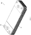
FIG. 1 is a schematic perspective view of a plate heat exchanger according to an embodiment of the present invention; -
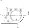
FIG. 2 is a schematic partial top view of the plate heat exchanger according to the embodiment of the present invention; -
FIG. 3 is a schematic partial cross-sectional view of the plate heat exchanger according to the embodiment of the present invention along line AA inFIG. 2 ; -
FIG. 4 is a schematic partial cross-sectional view of a heat exchange plate of a plate heat exchanger according to a first embodiment of the present invention along line AA inFIG. 2 ; -
FIG. 5 is a schematic partial cross-sectional view of a heat exchange plate of a plate heat exchanger according to a second embodiment of the present invention along line AA inFIG. 2 ; -
FIG. 6 is a schematic partial cross-sectional view of a heat exchange plate of a plate heat exchanger according to a third embodiment of the present invention along line AA inFIG. 2 ; -
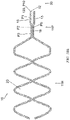
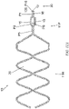
FIG. 7 is a schematic partial top view of a heat exchange plate of a plate heat exchanger according to a fourth embodiment of the present invention; -
FIG. 8A is a schematic partial cross-sectional view of a heat exchange plate of a plate heat exchanger according to a fifth embodiment of the present invention along a plane passing through an axis of a port shown inFIG. 2 ; -
FIG. 8B is a schematic partial cross-sectional view of the heat exchange plate of the plate heat exchanger according to the fifth embodiment of the present invention along another plane passing through the axis of the port shown inFIG. 2 ; -
FIG. 9A is a schematic partial cross-sectional view of a heat exchange plate of a plate heat exchanger according to a sixth embodiment of the present invention along a plane passing through the axis of the port shown inFIG. 2 ; -
FIG. 9B is a schematic partial cross-sectional view of the heat exchange plate of the plate heat exchanger according to the sixth embodiment of the present invention along another plane passing through the axis of the port shown inFIG. 2 ; -
FIG. 10A is a schematic partial cross-sectional view of a heat exchange plate of a plate heat exchanger according to a seventh embodiment of the present invention along a plane passing through the axis of the port shown inFIG. 2 ; -
FIG. 10B is a schematic partial cross-sectional view of the heat exchange plate of the plate heat exchanger according to the seventh embodiment of the present invention along another plane passing through the axis of the port shown inFIG. 2 ; -
FIG. 11A is a schematic partial cross-sectional view of a heat exchange plate of a plate heat exchanger according to an eighth embodiment of the present invention along a plane passing through the axis of the port shown inFIG. 2 ; -
FIG. 11B is a schematic partial cross-sectional view of the heat exchange plate of the plate heat exchanger according to the eighth embodiment of the present invention along another plane passing through the axis of the port shown inFIG. 2 ; -
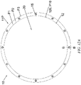
FIG. 12A is a schematic partial top view of a plate heat exchanger according to a ninth embodiment of the present invention; and -
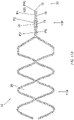
FIG. 12B is a schematic partial cross-sectional view of the heat exchange plate of the plate heat exchanger according to the ninth embodiment of the present invention along line BB shown inFIG. 12A . - The present invention will be further described below in conjunction with the accompanying drawings and specific implementations.
- As shown in
FIGS. 1 to 3 , aplate heat exchanger 100 according to an embodiment of the present invention comprises: a plurality ofheat exchange plates 10;heat exchange spaces 20 formed between adjacentheat exchange plates 10 of the plurality ofheat exchange plates 10; andports 30 formed in theheat exchange plates 10. Each of theports 30 is configured to distribute a refrigerant to someheat exchange spaces 20 of theheat exchange spaces 20. - Referring to
FIGS. 1 to 12B , theheat exchange plate 10 for theplate heat exchanger 100 according to embodiments of the present invention comprises: aheat exchange portion 11H and aport portion 11P; and anopening 12 formed in theport portion 11P and configured to form aport 30 of theheat exchanger 100. Theheat exchange portion 11H is provided with a corrugated structure, so that fluids having different temperatures exchange heat with each other on two sides of theheat exchange portion 11H. Theport portions 11P are substantially fitted together. Theheat exchange plate 10 comprises a first side and a second side (e.g., an upper side and a lower side of each of theheat exchange plates 10 inFIGS. 3 ,4 ,5 ,6 ,8A ,8B ,9A ,9B ,10A ,10B ,11A ,11B , and12B ) in a direction perpendicular to theheat exchange plate 10; and theport portion 11P is provided with acontact portion 16 that is in contact with theport portion 11P of anotherheat exchange plate 10 on the first side, and aprotrusion 15 protruding toward the second side relative to thecontact portion 16. For example, theport portion 11P has a surface PS on the first side, and a part of the surface PS of theport portion 11P is in contact with theport portion 11P of anotherheat exchange plate 10. - In some embodiments of the present invention, referring to
FIGS. 7 ,8A ,8B ,9A ,9B ,10A ,10B ,12A , and12B , theport portion 11P comprises a plurality ofprotrusions 15 distributed in a circumferential direction around theopening 12. For example, referring toFIGS. 7 and12A , when viewed in the direction perpendicular to theheat exchange plate 10, the plurality ofprotrusions 15 are each in a circular, rectangular or trapezoidal shape. - In some embodiments of the present invention, referring to
FIGS. 3 ,4 ,5 ,6 ,8A ,8B ,10A ,10B ,11A , and11B , theport portion 11P comprises anannular contact portion 16 and anannular protrusion 15 surrounding the opening 12, and theannular contact portion 16 and theannular protrusion 15 adjoin each other. For example, referring toFIG. 5 , theport portion 11P comprises at least twoannular protrusions 15 surrounding the opening 12, and twoannular protrusions 15 of the at least twoannular protrusions 15 adjoin each other and have different protrusion amounts relative to thecontact portion 16; or twoannular protrusions 15 of the at least twoannular protrusions 15 are separated by theannular contact portion 16. - In some embodiments of the present invention, referring to
FIGS. 3 to 12B , theport portion 11P comprises: a first annular portion P1 surrounding theopening 12, wherein an inner edge P10 of the first annular portion P1 constitutes anedge 120 of the opening 12; and a second annular portion P2 surrounding the first annular portion P1 and adjoining the first annular portion P1, wherein at least a part of at least one of the first annular portion P1 and the second annular portion P2 (e.g., one of the first annular portion P1 and the second annular portion P2) protrudes toward the second side to constitute aprotrusion 15. For example, one of the first annular portion P1 and the second annular portion P2 protrudes toward the second side to constitute aprotrusion 15. - Each of the first annular portion P1 and the second annular portion P2 has a predetermined width, and may be in a circular ring shape or other suitable shapes according to the shape of the
opening 12. - In some embodiments of the present invention, referring to
FIGS. 7 ,8A ,8B ,9A ,9B ,10A ,10B ,12A , and12B , a plurality of circumferentially-spaced parts of at least one of the first annular portion P1 and the second annular portion P2 (e.g., one of the first annular portion P1 and the second annular portion P2) protrude toward the second side to constitute a plurality ofprotrusions 15. A plurality of stepped reinforcing structures are uniformly arranged in a circumferential direction of the annular portion around theopening 12 of theheat exchange plate 10. For example, referring toFIG. 7 , noprotrusion 15 is provided in a region A and aprotrusion 15 is provided in a region B. This structure can be modified according to the size of the opening and the size of the heat exchange portion. - In some embodiments of the present invention, referring to
FIGS. 3 ,4 ,5 ,6 ,8A ,8B ,10A ,10B ,11A , and11B , the first annular portion P1 protrudes toward the second side to constitute anannular protrusion 15; or the second annular portion P2 protrudes toward the second side to constitute anannular protrusion 15. - In some embodiments of the present invention, referring to
FIGS. 7 ,8A , and8B , one of the first annular portion P1 and the second annular portion P2 protrudes toward the second side to constitute anannular protrusion 15, and a plurality of circumferentially-spaced parts of the other of the first annular portion P1 and the second annular portion P2 protrude toward the second side to constitute a plurality ofprotrusions 15. - In some embodiments of the present invention, referring to
FIGS. 5 ,10A ,10B ,11A ,11B ,12A , and12B , theport portion 11P comprises: a first annular portion P1 surrounding theopening 12, wherein an inner edge P10 of the first annular portion P1 constitutes anedge 120 of theopening 12; a second annular portion P2 surrounding the first annular portion P1 and adjoining the first annular portion P1; and a third annular portion P3 surrounding the second annular portion P2 and adjoining the second annular portion P2, wherein at least a part of at least one of the first annular portion P1, the second annular portion P2 and the third annular portion P3 protrudes toward the second side to constitute aprotrusion 15. - In some embodiments of the present invention, referring to
FIG. 5 , the second annular portion P2 and the third annular portion P3 protrude toward the second side to constituteprotrusions 15, at least a part of the first annular portion P1 constitutes acontact portion 16, and a protrusion amount of the second annular portion P2 relative to thecontact portion 16 is less than a protrusion amount of the third annular portion P3. - In some embodiments of the present invention, referring to
FIGS. 10A ,10B ,11A , and11B , one of the first annular portion P1, the second annular portion P2 and the third annular portion P3 protrudes toward the second side to constitute anannular protrusion 15, and a plurality of circumferentially-spaced parts of a further one of the first annular portion P1, the second annular portion P2 and the third annular portion P3 protrude toward the second side to constitute a plurality ofprotrusions 15. - In some embodiments of the present invention, referring to
FIGS. 10A ,10B ,11A , and11B , one of the first annular portion P1 and the second annular portion P2 protrudes toward the second side to constitute anannular protrusion 15, and a plurality of circumferentially-spaced parts of the third annular portion P3 protrude toward the second side to constitute a plurality ofprotrusions 15. - In some embodiments of the present invention, referring to
FIGS. 7 ,8A ,8B ,9A ,9B ,10A ,10B ,12A , and12B , the plurality ofprotrusions 15 are arranged at equal intervals in the circumferential direction. - In some embodiments of the present invention, referring to
FIGS. 7 and12A , when viewed in the direction perpendicular to theheat exchange plate 10, the plurality ofprotrusions 15 are each in a circular, rectangular or trapezoidal shape. - In some embodiments of the present invention, referring to
FIGS. 3 to 12B , theport portion 11P comprises: a plurality of annular portions surrounding theopening 12, wherein an inner edge P10 of the innermost annular portion constitutes anedge 120 of theopening 12, two adjacent annular portions of the plurality of annular portions adjoin each other, and at least a part of at least one of the plurality of annular portions protrudes toward the second side to constitute theprotrusion 15. - In some embodiments of the present invention, referring to
FIGS. 3 to 12B , at least one of the plurality of annular portions protrudes toward the second side to constitute anannular protrusion 15; or a plurality of circumferentially-spaced parts of at least one of the plurality of annular portions protrude toward the second side to constitute a plurality ofprotrusions 15. - In some embodiments of the present invention, referring to
FIGS. 5 ,10A ,10B ,11A ,11B ,12A , and12B , theport portion 11P comprises: at least three annular portions surrounding theopening 12, wherein an inner edge P10 of the innermost annular portion constitutes anedge 120 of theopening 12, two adjacent annular portions of the at least three annular portions adjoin each other, and at least a part of each of at least two of the at least three annular portions protrudes toward the second side to constitute theprotrusion 15. - In some embodiments of the present invention, referring to
FIGS. 5 ,10A ,10B ,11A ,11B ,12A , and12B , a protrusion amount of at least a part of one of the at least two annular portions is different from a protrusion amount of at least a part of the other of the at least two annular portions; or a protrusion amount of at least a part of one of the at least two annular portions is the same as a protrusion amount of at least a part of the other of the at least two annular portions. - In some embodiments of the present invention, referring to
FIGS. 5 ,10A ,10B ,11A ,11B ,12A , and12B , each of at least two of the at least three annular portions protrudes toward the second side to constitute anannular protrusion 15; a plurality of circumferentially-spaced parts of each of at least two of the at least three annular portions protrude toward the second side to constitute a plurality ofprotrusions 15; or a plurality of circumferentially-spaced parts of one of at least two of the at least three annular portions protrude toward the second side to constitute a plurality ofprotrusions 15, and the other of the at least two of the at least three annular portions protrudes toward the second side to constitute anannular protrusion 15. - In some embodiments of the present invention, referring to
FIGS. 3 ,4 ,5 ,6 ,8A ,8B ,9A ,9B ,10A ,10B ,11A ,11B , and12B ,protrusions 15 of two adjacentheat exchange plates 10 hermetically connected to each other at theport portions 11P thereof protrude in directions away from each other, and a gap between twoprotrusions 15 is in the range of 0.2-0.3 mm. - In some embodiments of the present invention, referring to
FIGS. 3 ,4 ,5 ,6 ,8A ,8B ,9A ,9B ,10A ,10B ,11A ,11B , and12B ,protrusions 15 of two adjacentheat exchange plates 10 hermetically connected to each other at theport portions 11P thereof protrude in directions away from each other, a gap between twoprotrusions 15 is in the range of 0.2-0.3 mm, and the gap between the twoprotrusions 15 is filled with a brazing alloy for brazing the plate heat exchanger, so as to braze the twoprotrusions 15 together. In this way, theprotrusions 15 can further reinforce theport portion 11P, for example. - In some embodiments of the present invention, the
heat exchange plate 10 is formed from a plate, such as by stamping. After theheat exchange plate 10 is formed, the plate has an undeformed portion that is not deformed toward the first side or the second side. The undeformed portion is in an initial plane, i.e., an undeformed plane in which the plate lies before being machined (e.g., stamped).Protrusions 15 protrude from the initial plane toward the second side, and at least one of a plurality of annular portions is not provided with a protrusion, i.e., is located in the initial plane. - According to embodiments of the present invention, referring to
FIGS. 3 to 12B , the height, shape and size, etc. of eachprotrusion 15 can be adjusted according to the size of a corrugated structure in a heat exchange region, and the number ofprotrusions 15 around each opening can also be adjusted accordingly. The height of each protrusion is less than that of each peak of the corrugated structure. - According to an embodiment of the present invention, when the size of a port of each heat exchange plate is larger and a larger number of heat exchange plates are stacked, a risk of warpage of the heat exchange plates can be significantly reduced, a product pass rate can be improved, and the flatness of the formed heat exchange plate in the vicinity of the opening for forming the port can be improved.
- According to an embodiment of the present invention, a stepped structure is provided in the vicinity of the opening of the heat exchange plate, i.e., the original entire plane is reconfigured as two or more planes with different heights, so that the structure can improve the flatness of the heat exchange plate. In addition, this structure can significantly enhance the strength of the formed heat exchange plate in the vicinity of the opening and prevent the occurrence of warpage.
- According to an embodiment of the present invention, warpage deformation that may occur if a large number of heat exchange plates are stacked or an opening of each heat exchange plate is larger is eliminated, the flatness of the heat exchange plate in the vicinity of the opening is improved, the brazing quality of the heat exchange plates is improved, and the strength of the entire structure of the heat exchanger is finally increased. In addition, the product pass rate is improved.
- It should be noted that the features in one or more of the above embodiments can be combined into new embodiments. The features in an embodiment can be used in a further embodiment unless the features in the embodiment conflict with the technical solution of the further embodiment.
Claims (15)
- A heat exchange plate for a plate heat exchanger, the heat exchange plate comprising:a heat exchange portion and a port portion, wherein fluids having different temperatures exchange heat with each other through the heat exchange portion, and an opening used as a port of the heat exchanger is formed in the port portion,wherein the heat exchange plate comprises a first side and a second side in a direction perpendicular to the heat exchange plate; and the port portion is provided with a contact portion that is in contact with the port portion of another heat exchange plate on the first side, and a protrusion protruding toward the second side relative to the contact portion.
- The heat exchange plate for a plate heat exchanger as claimed in claim 1, wherein
the port portion comprises a plurality of protrusions distributed in a circumferential direction around the opening. - The heat exchange plate for a plate heat exchanger as claimed in claim 2, wherein
when viewed in the direction perpendicular to the heat exchange plate, the plurality of protrusions are each in a circular, rectangular or trapezoidal shape. - The heat exchange plate for a plate heat exchanger as claimed in claim 1, wherein
the port portion comprises an annular contact portion and an annular protrusion surrounding the opening, and the annular contact portion and the annular protrusion adjoin each other. - The heat exchange plate for a plate heat exchanger as claimed in claim 4, wherein
the port portion comprises at least two annular protrusions surrounding the opening, and two of the at least two annular protrusions adjoin each other and have different protrusion amounts relative to the contact portion; or two of the at least two annular protrusions are separated by the annular contact portion. - The heat exchange plate for a plate heat exchanger as claimed in claim 1, wherein
the port portion comprises: a first annular portion surrounding the opening, wherein an inner edge of the first annular portion constitutes an edge of the opening; and a second annular portion surrounding the first annular portion and adjoining the first annular portion, wherein at least a part of one of the first annular portion and the second annular portion constitutes the protrusion. - The heat exchange plate for a plate heat exchanger as claimed in claim 6, whereina plurality of circumferentially-spaced parts of at least one of the first annular portion and the second annular portion constitute a plurality of protrusions; orone of the first annular portion and the second annular portion constitutes an annular protrusion; orone of the first annular portion and the second annular portion constitutes an annular protrusion, and a plurality of circumferentially-spaced parts of the other of the first annular portion and the second annular portion constitute a plurality of protrusions.
- The heat exchange plate for a plate heat exchanger as claimed in claim 1, wherein
the port portion comprises: a first annular portion surrounding the opening, wherein an inner edge of the first annular portion constitutes an edge of the opening; a second annular portion surrounding the first annular portion and adjoining the first annular portion; and a third annular portion surrounding the second annular portion and adjoining the second annular portion, wherein at least a part of at least one of the first annular portion, the second annular portion and the third annular portion constitutes a protrusion. - The heat exchange plate for a plate heat exchanger as claimed in claim 8, wherein
the second annular portion and the third annular portion protrude toward the second side relative to a part of a surface of the port portion to constitute protrusions, at least a part of the first annular portion constitutes a contact portion, and a protrusion amount of the second annular portion relative to the contact portion is less than a protrusion amount of the third annular portion. - The heat exchange plate for a plate heat exchanger as claimed in claim 8, wherein
one of the first annular portion, the second annular portion and the third annular portion constitutes an annular protrusion, and a plurality of circumferentially-spaced parts of a further one of the first annular portion, the second annular portion and the third annular portion constitute a plurality of protrusions. - The heat exchange plate for a plate heat exchanger as claimed in claim 1, wherein
the port portion comprises: a plurality of annular portions surrounding the opening, wherein an inner edge of the innermost annular portion constitutes an edge of the opening, two adjacent annular portions of the plurality of annular portions adjoin each other, and at least a part of at least one of the plurality of annular portions constitutes the protrusion. - The heat exchange plate for a plate heat exchanger as claimed in claim 11, wherein
at least one of the plurality of annular portions protrudes toward the second side relative to a part of a surface of the port portion to constitute an annular protrusion; or a plurality of circumferentially-spaced parts of at least one of the plurality of annular portions protrude toward the second side relative to the part of the surface of the port portion to constitute a plurality of protrusions. - A plate heat exchanger, comprising:
a plurality of heat exchange plates, each being the heat exchange plate as claimed in any one of claims 1 to 12. - The plate heat exchanger as claimed in claim 13, wherein
protrusions of two adjacent heat exchange plates hermetically connected to each other at the port portions thereof protrude in directions away from each other, and a gap between two protrusions is in the range of 0.2-0.3 mm. - The plate heat exchanger as claimed in claim 13, wherein
protrusions of two adjacent heat exchange plates hermetically connected to each other at the port portions thereof protrude in directions away from each other, a gap between two protrusions is in the range of 0.2-0.3 mm, and the gap between the two protrusions is filled with a brazing alloy for brazing the plate heat exchanger, so as to braze the two protrusions together.
Applications Claiming Priority (3)
| Application Number | Priority Date | Filing Date | Title |
|---|---|---|---|
| CN201911063164 | 2019-10-31 | ||
| CN201911189175.0A CN112747613B (en) | 2019-10-31 | 2019-11-27 | Heat exchange plate for plate heat exchanger and plate heat exchanger |
| PCT/CN2020/124321 WO2021083189A1 (en) | 2019-10-31 | 2020-10-28 | Heat exchange plate for use in plate-type heat exchanger, and plate-type heat exchanger |
Publications (2)
| Publication Number | Publication Date |
|---|---|
| EP4053488A1 true EP4053488A1 (en) | 2022-09-07 |
| EP4053488A4 EP4053488A4 (en) | 2023-11-08 |
Family
ID=75645684
Family Applications (1)
| Application Number | Title | Priority Date | Filing Date |
|---|---|---|---|
| EP20880738.8A Withdrawn EP4053488A4 (en) | 2019-10-31 | 2020-10-28 | HEAT EXCHANGE PLATE FOR A PLATE HEAT EXCHANGER AND PLATE HEAT EXCHANGER |
Country Status (5)
| Country | Link |
|---|---|
| US (1) | US20230147560A1 (en) |
| EP (1) | EP4053488A4 (en) |
| CN (1) | CN112747613B (en) |
| MX (1) | MX2022005030A (en) |
| WO (1) | WO2021083189A1 (en) |
Family Cites Families (20)
| Publication number | Priority date | Publication date | Assignee | Title |
|---|---|---|---|---|
| SE9000712L (en) * | 1990-02-28 | 1991-08-29 | Alfa Laval Thermal | PERMANENT COMBINED PLATE HEAT EXCHANGER |
| SE502984C2 (en) * | 1993-06-17 | 1996-03-04 | Alfa Laval Thermal Ab | Flat heat exchanger with specially designed door sections |
| US5462113A (en) * | 1994-06-20 | 1995-10-31 | Flatplate, Inc. | Three-circuit stacked plate heat exchanger |
| SE512240C2 (en) * | 1998-06-24 | 2000-02-14 | Alfa Laval Ab | Ways of joining at least four heat transfer plates to a plate package and plate package |
| SE514714C2 (en) * | 1999-08-27 | 2001-04-09 | Alfa Laval Ab | Soldered plate heat exchanger with double wall plates without internal contact opposite the solder connections |
| SE524176C2 (en) * | 2002-11-01 | 2004-07-06 | Ep Technology Ab | Heat exchanger with amplifier |
| SE524783C2 (en) * | 2003-02-11 | 2004-10-05 | Alfa Laval Corp Ab | Plate package, plate heat exchanger and plate module |
| SE524307C2 (en) * | 2003-07-24 | 2004-07-27 | Swep Int Ab | Plate type heat exchanger production method, forms plate with double wall construction to allow drainage of any leaking fluid |
| SE532345C2 (en) * | 2007-12-21 | 2009-12-22 | Alfa Laval Corp Ab | Heat exchanger plate, heat exchanger cartridge and heat exchanger with gasket groove |
| KR101316858B1 (en) * | 2011-12-08 | 2013-10-10 | 현대자동차주식회사 | Condenser for vehicle |
| SI2674716T1 (en) * | 2012-06-14 | 2015-08-31 | Alfa Laval Corporate Ab | A plate heat exchanger |
| CN105637313B (en) * | 2013-10-14 | 2018-04-03 | 艾雷克股份公司 | Plate and heat exchanger for heat exchanger |
| JP2016176618A (en) * | 2015-03-19 | 2016-10-06 | パナソニックIpマネジメント株式会社 | Heat exchanger |
| JP6616115B2 (en) * | 2015-07-30 | 2019-12-04 | 株式会社マーレ フィルターシステムズ | Heat exchanger |
| SE542049C2 (en) * | 2016-04-06 | 2020-02-18 | Alfa Laval Corp Ab | A heat exchanger plate, a plate heat exchanger, and a method of making a plate heat exchanger |
| SE541284C2 (en) * | 2016-05-30 | 2019-06-11 | Alfa Laval Corp Ab | A plate heat exchanger |
| SE541355C2 (en) * | 2016-12-22 | 2019-08-13 | Alfa Laval Corp Ab | A plate heat exchanger with six ports for three different media |
| PT3351886T (en) * | 2017-01-19 | 2019-07-31 | Alfa Laval Corp Ab | Heat exchanging plate and heat exchanger |
| CN206787364U (en) * | 2017-06-06 | 2017-12-22 | 江苏菲尔克斯换热科技有限公司 | A kind of heat exchanger plate and plate type heat exchanger |
| CN211575949U (en) * | 2020-01-22 | 2020-09-25 | 丹佛斯有限公司 | Plate heat exchanger |
-
2019
- 2019-11-27 CN CN201911189175.0A patent/CN112747613B/en active Active
-
2020
- 2020-10-28 MX MX2022005030A patent/MX2022005030A/en unknown
- 2020-10-28 WO PCT/CN2020/124321 patent/WO2021083189A1/en not_active Ceased
- 2020-10-28 EP EP20880738.8A patent/EP4053488A4/en not_active Withdrawn
- 2020-10-28 US US17/773,118 patent/US20230147560A1/en not_active Abandoned
Also Published As
| Publication number | Publication date |
|---|---|
| MX2022005030A (en) | 2022-07-19 |
| CN112747613B (en) | 2023-06-13 |
| WO2021083189A1 (en) | 2021-05-06 |
| CN112747613A (en) | 2021-05-04 |
| EP4053488A4 (en) | 2023-11-08 |
| US20230147560A1 (en) | 2023-05-11 |
Similar Documents
| Publication | Publication Date | Title |
|---|---|---|
| US9250019B2 (en) | Plate heat exchanger | |
| EP3115733B1 (en) | Heat exchange plate for plate-type heat exchanger and plate-type heat exchanger provided with said heat exchange plate | |
| CN111164367B (en) | Heat transfer plates and plate packs for heat exchangers comprising a plurality of such heat transfer plates | |
| EP3115731B1 (en) | Heat exchange plate used for plate-type heat exchanger and plate-type heat exchanger provided with the heat exchange plate | |
| US20070006998A1 (en) | Heat exchanger with plate projections | |
| US20220228816A1 (en) | A dual media safety heat exchanger | |
| EP4012323B1 (en) | Distributor for plate heat exchanger, and plate heat exchanger | |
| EP3640577A2 (en) | Heat exchanger plate with strenghened diagonal area | |
| US11874071B2 (en) | Heat exchanger plate, a plate heat exchanger, and a method of making a plate heat exchanger | |
| EP3032208B1 (en) | Gasket groove for a plate heat exchanger | |
| US11821694B2 (en) | Heat transfer plate and cassette for plate heat exchanger | |
| EP4086561B1 (en) | Chip, chip assembly, core and intercooler | |
| US20230147560A1 (en) | Heat exchange plate for plate heat exchanger, and plate heat exchanger | |
| US11105559B2 (en) | Drawn cup-type heat exchanger | |
| EP4095478B1 (en) | Plate heat exchanger | |
| JP2017003173A (en) | Heat transfer plate for plate heat exchanger and plate heat exchanger equipped with the same | |
| EP3489606B1 (en) | Heat transfer plate for plate heat exchanger and plate heat exchanger with the same | |
| CN219934739U (en) | Plate heat exchanger | |
| EP4718010A1 (en) | Plate heat exchanger | |
| US6976531B2 (en) | Heat exchanger, method of forming a sleeve which may be used in the heat exchanger, and a sleeve formed by the method | |
| RU2527776C1 (en) | Heat exchanger, heat exchanging plate and method of manufacturing heat exchanger | |
| JP2022147760A (en) | Plate type heat exchanger | |
| JP2017020694A (en) | Plate type heat exchanger | |
| DK180387B1 (en) | Plate kind heat exchanger with end plates | |
| EP4509791A1 (en) | Plate heat exchanger |
Legal Events
| Date | Code | Title | Description |
|---|---|---|---|
| STAA | Information on the status of an ep patent application or granted ep patent |
Free format text: STATUS: THE INTERNATIONAL PUBLICATION HAS BEEN MADE |
|
| PUAI | Public reference made under article 153(3) epc to a published international application that has entered the european phase |
Free format text: ORIGINAL CODE: 0009012 |
|
| STAA | Information on the status of an ep patent application or granted ep patent |
Free format text: STATUS: REQUEST FOR EXAMINATION WAS MADE |
|
| 17P | Request for examination filed |
Effective date: 20220524 |
|
| AK | Designated contracting states |
Kind code of ref document: A1 Designated state(s): AL AT BE BG CH CY CZ DE DK EE ES FI FR GB GR HR HU IE IS IT LI LT LU LV MC MK MT NL NO PL PT RO RS SE SI SK SM TR |
|
| DAV | Request for validation of the european patent (deleted) | ||
| DAX | Request for extension of the european patent (deleted) | ||
| P01 | Opt-out of the competence of the unified patent court (upc) registered |
Effective date: 20230713 |
|
| A4 | Supplementary search report drawn up and despatched |
Effective date: 20231010 |
|
| RIC1 | Information provided on ipc code assigned before grant |
Ipc: F28F 9/02 20060101ALI20231004BHEP Ipc: F28F 3/04 20060101ALI20231004BHEP Ipc: F28D 9/00 20060101ALI20231004BHEP Ipc: F28D 9/04 20060101ALI20231004BHEP Ipc: F28F 3/08 20060101AFI20231004BHEP |
|
| STAA | Information on the status of an ep patent application or granted ep patent |
Free format text: STATUS: EXAMINATION IS IN PROGRESS |
|
| 17Q | First examination report despatched |
Effective date: 20250711 |
|
| STAA | Information on the status of an ep patent application or granted ep patent |
Free format text: STATUS: THE APPLICATION IS DEEMED TO BE WITHDRAWN |
|
| 18D | Application deemed to be withdrawn |
Effective date: 20251112 |