EP4053477A1 - Refrigeration device - Google Patents
Refrigeration device Download PDFInfo
- Publication number
- EP4053477A1 EP4053477A1 EP20883120.6A EP20883120A EP4053477A1 EP 4053477 A1 EP4053477 A1 EP 4053477A1 EP 20883120 A EP20883120 A EP 20883120A EP 4053477 A1 EP4053477 A1 EP 4053477A1
- Authority
- EP
- European Patent Office
- Prior art keywords
- refrigerant
- compressor
- control
- control unit
- revolutions
- Prior art date
- Legal status (The legal status is an assumption and is not a legal conclusion. Google has not performed a legal analysis and makes no representation as to the accuracy of the status listed.)
- Granted
Links
Images



Classifications
-
- F—MECHANICAL ENGINEERING; LIGHTING; HEATING; WEAPONS; BLASTING
- F25—REFRIGERATION OR COOLING; COMBINED HEATING AND REFRIGERATION SYSTEMS; HEAT PUMP SYSTEMS; MANUFACTURE OR STORAGE OF ICE; LIQUEFACTION SOLIDIFICATION OF GASES
- F25B—REFRIGERATION MACHINES, PLANTS OR SYSTEMS; COMBINED HEATING AND REFRIGERATION SYSTEMS; HEAT PUMP SYSTEMS
- F25B41/00—Fluid-circulation arrangements
- F25B41/40—Fluid line arrangements
-
- F—MECHANICAL ENGINEERING; LIGHTING; HEATING; WEAPONS; BLASTING
- F25—REFRIGERATION OR COOLING; COMBINED HEATING AND REFRIGERATION SYSTEMS; HEAT PUMP SYSTEMS; MANUFACTURE OR STORAGE OF ICE; LIQUEFACTION SOLIDIFICATION OF GASES
- F25B—REFRIGERATION MACHINES, PLANTS OR SYSTEMS; COMBINED HEATING AND REFRIGERATION SYSTEMS; HEAT PUMP SYSTEMS
- F25B49/00—Arrangement or mounting of control or safety devices
- F25B49/02—Arrangement or mounting of control or safety devices for compression type machines, plants or systems
-
- F—MECHANICAL ENGINEERING; LIGHTING; HEATING; WEAPONS; BLASTING
- F25—REFRIGERATION OR COOLING; COMBINED HEATING AND REFRIGERATION SYSTEMS; HEAT PUMP SYSTEMS; MANUFACTURE OR STORAGE OF ICE; LIQUEFACTION SOLIDIFICATION OF GASES
- F25B—REFRIGERATION MACHINES, PLANTS OR SYSTEMS; COMBINED HEATING AND REFRIGERATION SYSTEMS; HEAT PUMP SYSTEMS
- F25B13/00—Compression machines, plants or systems, with reversible cycle
-
- F—MECHANICAL ENGINEERING; LIGHTING; HEATING; WEAPONS; BLASTING
- F25—REFRIGERATION OR COOLING; COMBINED HEATING AND REFRIGERATION SYSTEMS; HEAT PUMP SYSTEMS; MANUFACTURE OR STORAGE OF ICE; LIQUEFACTION SOLIDIFICATION OF GASES
- F25B—REFRIGERATION MACHINES, PLANTS OR SYSTEMS; COMBINED HEATING AND REFRIGERATION SYSTEMS; HEAT PUMP SYSTEMS
- F25B31/00—Compressor arrangements
- F25B31/002—Lubrication
- F25B31/004—Lubrication oil recirculating arrangements
-
- F—MECHANICAL ENGINEERING; LIGHTING; HEATING; WEAPONS; BLASTING
- F25—REFRIGERATION OR COOLING; COMBINED HEATING AND REFRIGERATION SYSTEMS; HEAT PUMP SYSTEMS; MANUFACTURE OR STORAGE OF ICE; LIQUEFACTION SOLIDIFICATION OF GASES
- F25B—REFRIGERATION MACHINES, PLANTS OR SYSTEMS; COMBINED HEATING AND REFRIGERATION SYSTEMS; HEAT PUMP SYSTEMS
- F25B41/00—Fluid-circulation arrangements
- F25B41/20—Disposition of valves, e.g. of on-off valves or flow control valves
- F25B41/22—Disposition of valves, e.g. of on-off valves or flow control valves between evaporator and compressor
-
- F—MECHANICAL ENGINEERING; LIGHTING; HEATING; WEAPONS; BLASTING
- F25—REFRIGERATION OR COOLING; COMBINED HEATING AND REFRIGERATION SYSTEMS; HEAT PUMP SYSTEMS; MANUFACTURE OR STORAGE OF ICE; LIQUEFACTION SOLIDIFICATION OF GASES
- F25B—REFRIGERATION MACHINES, PLANTS OR SYSTEMS; COMBINED HEATING AND REFRIGERATION SYSTEMS; HEAT PUMP SYSTEMS
- F25B41/00—Fluid-circulation arrangements
- F25B41/30—Expansion means; Dispositions thereof
- F25B41/31—Expansion valves
-
- F—MECHANICAL ENGINEERING; LIGHTING; HEATING; WEAPONS; BLASTING
- F25—REFRIGERATION OR COOLING; COMBINED HEATING AND REFRIGERATION SYSTEMS; HEAT PUMP SYSTEMS; MANUFACTURE OR STORAGE OF ICE; LIQUEFACTION SOLIDIFICATION OF GASES
- F25B—REFRIGERATION MACHINES, PLANTS OR SYSTEMS; COMBINED HEATING AND REFRIGERATION SYSTEMS; HEAT PUMP SYSTEMS
- F25B43/00—Arrangements for separating or purifying gases or liquids; Arrangements for vaporising the residuum of liquid refrigerant, e.g. by heat
- F25B43/006—Accumulators
-
- F—MECHANICAL ENGINEERING; LIGHTING; HEATING; WEAPONS; BLASTING
- F25—REFRIGERATION OR COOLING; COMBINED HEATING AND REFRIGERATION SYSTEMS; HEAT PUMP SYSTEMS; MANUFACTURE OR STORAGE OF ICE; LIQUEFACTION SOLIDIFICATION OF GASES
- F25B—REFRIGERATION MACHINES, PLANTS OR SYSTEMS; COMBINED HEATING AND REFRIGERATION SYSTEMS; HEAT PUMP SYSTEMS
- F25B43/00—Arrangements for separating or purifying gases or liquids; Arrangements for vaporising the residuum of liquid refrigerant, e.g. by heat
- F25B43/02—Arrangements for separating or purifying gases or liquids; Arrangements for vaporising the residuum of liquid refrigerant, e.g. by heat for separating lubricants from the refrigerant
-
- F—MECHANICAL ENGINEERING; LIGHTING; HEATING; WEAPONS; BLASTING
- F25—REFRIGERATION OR COOLING; COMBINED HEATING AND REFRIGERATION SYSTEMS; HEAT PUMP SYSTEMS; MANUFACTURE OR STORAGE OF ICE; LIQUEFACTION SOLIDIFICATION OF GASES
- F25B—REFRIGERATION MACHINES, PLANTS OR SYSTEMS; COMBINED HEATING AND REFRIGERATION SYSTEMS; HEAT PUMP SYSTEMS
- F25B49/00—Arrangement or mounting of control or safety devices
- F25B49/02—Arrangement or mounting of control or safety devices for compression type machines, plants or systems
- F25B49/022—Compressor control arrangements
-
- F—MECHANICAL ENGINEERING; LIGHTING; HEATING; WEAPONS; BLASTING
- F25—REFRIGERATION OR COOLING; COMBINED HEATING AND REFRIGERATION SYSTEMS; HEAT PUMP SYSTEMS; MANUFACTURE OR STORAGE OF ICE; LIQUEFACTION SOLIDIFICATION OF GASES
- F25B—REFRIGERATION MACHINES, PLANTS OR SYSTEMS; COMBINED HEATING AND REFRIGERATION SYSTEMS; HEAT PUMP SYSTEMS
- F25B2500/00—Problems to be solved
- F25B2500/16—Lubrication
-
- F—MECHANICAL ENGINEERING; LIGHTING; HEATING; WEAPONS; BLASTING
- F25—REFRIGERATION OR COOLING; COMBINED HEATING AND REFRIGERATION SYSTEMS; HEAT PUMP SYSTEMS; MANUFACTURE OR STORAGE OF ICE; LIQUEFACTION SOLIDIFICATION OF GASES
- F25B—REFRIGERATION MACHINES, PLANTS OR SYSTEMS; COMBINED HEATING AND REFRIGERATION SYSTEMS; HEAT PUMP SYSTEMS
- F25B2600/00—Control issues
- F25B2600/02—Compressor control
- F25B2600/025—Compressor control by controlling speed
-
- F—MECHANICAL ENGINEERING; LIGHTING; HEATING; WEAPONS; BLASTING
- F25—REFRIGERATION OR COOLING; COMBINED HEATING AND REFRIGERATION SYSTEMS; HEAT PUMP SYSTEMS; MANUFACTURE OR STORAGE OF ICE; LIQUEFACTION SOLIDIFICATION OF GASES
- F25B—REFRIGERATION MACHINES, PLANTS OR SYSTEMS; COMBINED HEATING AND REFRIGERATION SYSTEMS; HEAT PUMP SYSTEMS
- F25B2600/00—Control issues
- F25B2600/02—Compressor control
- F25B2600/025—Compressor control by controlling speed
- F25B2600/0253—Compressor control by controlling speed with variable speed
-
- F—MECHANICAL ENGINEERING; LIGHTING; HEATING; WEAPONS; BLASTING
- F25—REFRIGERATION OR COOLING; COMBINED HEATING AND REFRIGERATION SYSTEMS; HEAT PUMP SYSTEMS; MANUFACTURE OR STORAGE OF ICE; LIQUEFACTION SOLIDIFICATION OF GASES
- F25B—REFRIGERATION MACHINES, PLANTS OR SYSTEMS; COMBINED HEATING AND REFRIGERATION SYSTEMS; HEAT PUMP SYSTEMS
- F25B2600/00—Control issues
- F25B2600/25—Control of valves
- F25B2600/2513—Expansion valves
-
- F—MECHANICAL ENGINEERING; LIGHTING; HEATING; WEAPONS; BLASTING
- F25—REFRIGERATION OR COOLING; COMBINED HEATING AND REFRIGERATION SYSTEMS; HEAT PUMP SYSTEMS; MANUFACTURE OR STORAGE OF ICE; LIQUEFACTION SOLIDIFICATION OF GASES
- F25B—REFRIGERATION MACHINES, PLANTS OR SYSTEMS; COMBINED HEATING AND REFRIGERATION SYSTEMS; HEAT PUMP SYSTEMS
- F25B2700/00—Sensing or detecting of parameters; Sensors therefor
- F25B2700/19—Pressures
-
- F—MECHANICAL ENGINEERING; LIGHTING; HEATING; WEAPONS; BLASTING
- F25—REFRIGERATION OR COOLING; COMBINED HEATING AND REFRIGERATION SYSTEMS; HEAT PUMP SYSTEMS; MANUFACTURE OR STORAGE OF ICE; LIQUEFACTION SOLIDIFICATION OF GASES
- F25B—REFRIGERATION MACHINES, PLANTS OR SYSTEMS; COMBINED HEATING AND REFRIGERATION SYSTEMS; HEAT PUMP SYSTEMS
- F25B2700/00—Sensing or detecting of parameters; Sensors therefor
- F25B2700/21—Temperatures
- F25B2700/2109—Temperatures of a separator
-
- F—MECHANICAL ENGINEERING; LIGHTING; HEATING; WEAPONS; BLASTING
- F25—REFRIGERATION OR COOLING; COMBINED HEATING AND REFRIGERATION SYSTEMS; HEAT PUMP SYSTEMS; MANUFACTURE OR STORAGE OF ICE; LIQUEFACTION SOLIDIFICATION OF GASES
- F25B—REFRIGERATION MACHINES, PLANTS OR SYSTEMS; COMBINED HEATING AND REFRIGERATION SYSTEMS; HEAT PUMP SYSTEMS
- F25B2700/00—Sensing or detecting of parameters; Sensors therefor
- F25B2700/21—Temperatures
- F25B2700/2115—Temperatures of a compressor or the drive means therefor
- F25B2700/21151—Temperatures of a compressor or the drive means therefor at the suction side of the compressor
Definitions
- the present disclosure relates to a refrigeration apparatus, in particular to a refrigeration apparatus in which a container is disposed between an evaporator and a compressor.
- Patent Literature 1 Japanese Laid-Open Patent Publication No. 2016-211774 discloses an invention that executes an operation of stirring the separated refrigerant and refrigerating machine oil to solve the separation state.
- Patent Literature 1 Japanese Laid-Open Patent Publication No. 2016-211774 discloses the invention that operates the compressor at a high number of revolutions in order to stir the separated refrigerant and refrigerating machine oil, but it may not be preferable in some situations to increase the number of revolutions of the compressor in such a way.
- a refrigeration apparatus of a first aspect includes a refrigerant circuit, a detection unit, and a control unit.
- a compressor, a radiator, an expansion valve, an evaporator, and a container are connected in order.
- the refrigerant flows inside the refrigerant circuit.
- the detection unit detects the temperature or pressure of the refrigerant.
- the control unit controls the number of revolutions of the compressor and the opening degree of the expansion valve. On determination that the refrigerant and a lubricating oil are separated inside the container based on a detection result of the detection unit, the control unit executes first control and second control.
- the first control is control to decrease the number of revolutions of the compressor.
- the second control sets the opening degree of the expansion valve to a predetermined opening degree.
- the first and second control to decrease the number of revolutions of the compressor and set the opening degree of the expansion valve to a predetermined opening degree is executed when the refrigerant and the lubricating oil are separated inside the container. Therefore, the pressure on the suction side of the compressor including the container (hereinafter referred to as low pressure value) can be increased. This makes it possible to change the pressure and temperature in the container to solve the separation state between the refrigerant and the lubricating oil.
- the refrigeration apparatus of a second aspect is the refrigeration apparatus of the first aspect, in which in the second control, the control unit sets the opening degree of the expansion valve to an opening degree of a fully open position or 90% or more of the fully open position.
- the opening degree of the expansion valve is near the fully open position when the refrigerant and the lubricating oil are separated inside the container, a large amount of high-temperature refrigerant flows into the container. This solves the separation state of the refrigerant and the lubricating oil at an early stage.
- the refrigeration apparatus of a third aspect is the refrigeration apparatus of the first aspect or the second aspect, in which in the first control, the control unit decreases the number of revolutions of the compressor to set the number of revolutions of the compressor to a predetermined number of revolutions.
- the refrigeration apparatus of a fourth aspect is the refrigeration apparatus of the third aspect, in which the control unit has an oil return operation other than the first control and the second control.
- the oil return operation is an operation of returning the lubricating oil staying in the refrigerant circuit except the compressor to the compressor.
- the refrigeration apparatus of the fourth aspect also has the oil return operation of the conventional refrigeration apparatus.
- the oil return operation in which the motor of the compressor is turned at a relatively high number of revolutions, may not be preferable as an operation to solve the separation state between the refrigerant and the lubricating oil inside the container. Therefore, the control unit of the refrigeration apparatus of the fourth aspect has, apart from the oil return operation, an operation to solve the separation between the refrigerant and the lubricating oil in the container by the first control and second control.
- the refrigeration apparatus of a fifth aspect is the refrigeration apparatus of the fourth aspect, in which when a condition that an integrated value of an amount of the refrigerant circulating in the refrigerant circuit exceeds a threshold value is satisfied, the control unit executes the oil return operation.
- the refrigeration apparatus of a sixth aspect is the refrigeration apparatus of the fourth aspect or the fifth aspect, in which the predetermined number of revolutions in the first control is smaller than the number of revolutions of the compressor in the oil return operation.
- the number of revolutions of the compressor is decreased. Since the compressor is turned at a lower number of revolutions (predetermined number of revolutions) unlike the oil return operation, the pressure in the container increases and the separation state between the refrigerant and the lubricating oil in the container is more easily solved.
- the refrigeration apparatus of a seventh aspect is the refrigeration apparatus of any one of the first aspect to the sixth aspect, in which when a request for stopping the compressor is received, the control unit determines whether to execute the first control and the second control before stopping the compressor based on a detection result of the detection unit.
- the first control and the second control are executed before stopping the compressor. Therefore, the situation in which the compressor is stopped while the refrigerant and the lubricating oil are separated in the container and the compressor runs out of lubricating oil when the compressor is started again is inhibited.
- the request for stopping the compressor is a stop request based on an operation stop manipulation by a user of the refrigeration apparatus, or a stop request when the request for refrigerant circulation in a user-side unit of the refrigeration apparatus is temporarily canceled.
- the latter stop request is, for example, a thermo-off signal in the indoor unit, which is the user-side unit of an air conditioning apparatus, when the room temperature in the cooling operation becomes less than the set temperature.
- the refrigeration apparatus of an eighth aspect is the refrigeration apparatus of any one of the first aspect to the sixth aspect, in which when a request to stop the compressor is received, the control unit determines whether the refrigerant and the lubricating oil are separated inside the container by a first criterion based on the detection result of the detection unit. When the request to stop the compressor is not received, the control unit determines whether the refrigerant and the lubricating oil are separated inside the container by a second criterion different from the first criterion based on the detection result of the detection unit.
- the first control and second control to solve the separation state between the refrigerant and the lubricating oil can be executed.
- the criterion for determining whether the refrigerant and the lubricating oil are separated inside the container is changed depending on whether the request to stop the compressor is received or not. This makes it possible, for example, to decrease the frequency at which the first and second control is executed when the compressor is operating, and to increase the frequency at which the first and second control is executed when the compressor stops.
- the refrigeration apparatus of a ninth aspect is the refrigeration apparatus of any one of the first aspect to the eighth aspect, in which the detection unit includes a sensor.
- the sensor measures the temperature of the refrigerant in the container or the temperature of the refrigerant flowing through the refrigerant pipe connected to the container.
- the temperature of the refrigerant in the container can be accurately detected from the measured values of the temperature sensor and/or pressure sensor.
- the refrigeration apparatus of a tenth aspect is the refrigeration apparatus of any one of the first aspect to the ninth aspect, in which the refrigerant circulating through the refrigerant circuit is R32.
- the refrigeration apparatus of an eleventh aspect is the refrigeration apparatus of any one of the first aspect to the tenth aspect, in which on determination that the refrigerant and the lubricating oil are separated inside the container from the detection result of the detection unit, the control unit executes the first control and the second control to keep operating the compressor for a predetermined period of 1 minute to 10 minutes.
- FIG. 1 is a schematic configuration diagram of an air conditioning apparatus 1 (refrigeration apparatus).
- the air conditioning apparatus 1 is an apparatus capable of cooling and heating a room of a building or the like by a vapor compression refrigeration cycle.
- the air conditioning apparatus 1 includes an outdoor unit 2 and an indoor unit 4.
- the outdoor unit 2 and the indoor unit 4 are connected via a liquid-refrigerant connection pipe 5 and a gas-refrigerant connection pipe 6.
- a refrigerant circuit 10 that constitutes the vapor compression refrigeration cycle of the air conditioning apparatus 1 is configured by the outdoor unit 2 and the indoor unit 4 being connected via the refrigerant connection pipes 5 and 6.
- Difluoromethane (R32) which is a refrigerant, is charged in the refrigerant circuit 10.
- Refrigerating machine oil which is immiscible with the refrigerant, is also charged in the refrigerant circuit 10 together with the refrigerant.
- the indoor unit 4 is installed indoors and constitutes part of the refrigerant circuit 10.
- the indoor unit 4 includes an indoor heat exchanger 41.
- the indoor heat exchanger 41 functions as an evaporator for a refrigerant to cool indoor air, and in a heating operation, the indoor heat exchanger 41 functions as a radiator for a refrigerant to heat indoor air.
- a first end of the indoor heat exchanger 41 is connected to the liquid-refrigerant connection pipe 5.
- a second end of the indoor heat exchanger 41 is connected to the gas-refrigerant connection pipe 6.
- the indoor unit 4 includes an indoor fan 42.
- the indoor fan 42 sucks indoor air into the indoor unit 4, exchanges heat with the refrigerant in the indoor heat exchanger 41, and then supplies the air indoors as supply air.
- the indoor fan 42 is, for example, a centrifugal fan, a multi-blade fan, or the like driven by an indoor fan motor 43.
- the indoor fan motor 43 can change a frequency (number of revolutions) by an inverter.
- the indoor unit 4 includes various sensors.
- the indoor unit 4 includes a liquid pipe temperature sensor 56, an intermediate temperature sensor 57, and an indoor temperature sensor 58.
- the liquid pipe temperature sensor 56 detects a temperature Trl of the refrigerant in the liquid side refrigerant pipe of the indoor heat exchanger 41.
- the intermediate temperature sensor 57 detects a temperature Trm of the refrigerant in an intermediate portion of the indoor heat exchanger 41.
- the indoor temperature sensor 58 detects a temperature Tra of the indoor air sucked into the indoor unit 4.
- the outdoor unit 2 is installed outdoors and constitutes part of the refrigerant circuit 10.
- the outdoor unit 2 includes a compressor 21, a four-way switching valve 22, an outdoor heat exchanger 23, an expansion valve 24, a liquid-side shutoff valve 26, a gas-side shutoff valve 27, and an accumulator 28.
- the outdoor unit 2 includes an outdoor fan 36.
- the compressor 21 compresses a low-pressure refrigerant in the refrigeration cycle until the refrigerant turns into a high-pressure refrigerant.
- the compressor 21 drives a positive-displacement compression element (not shown), such as a rotary type or scroll type, to rotate by a compressor motor 21a.
- a rotary compressor with closed structure is used as the compressor 21, as the compressor 21, a rotary compressor with closed structure is used.
- the compressor motor 21a can change a frequency (number of revolutions) by an inverter.
- a suction pipe 31 is connected to a suction side of the compressor 21, and a discharge pipe 32 is connected to a discharge side.
- the suction pipe 31 connects the suction side of the compressor 21 to a first port 22a of the four-way switching valve 22.
- the suction pipe 31 is provided with the accumulator 28.
- the suction pipe 31 is divided into a first pipe 31a and a second pipe 31b before and after the accumulator 28.
- the accumulator 28 is a container that temporarily stores the refrigerant sucked into the compressor 21.
- the accumulator 28 will be described in detail later with reference to FIG. 2 .
- the discharge pipe 32 is a refrigerant pipe connecting the discharge side of the compressor 21 to a second port 22b of the four-way switching valve 22.
- the four-way switching valve 22 switches a refrigerant flow direction in the refrigerant circuit 10.
- the four-way switching valve 22 switches to the cooling cycle state in which the outdoor heat exchanger 23 functions as a radiator for the refrigerant compressed in the compressor 21, and the indoor heat exchanger 41 functions as an evaporator for the refrigerant that has radiated heat in the outdoor heat exchanger 23.
- the four-way switching valve 22 switches such that the second port 22b and a third port 22c communicate with each other, and the first port 22a and a fourth port 22d communicate with each other.
- the discharge side of the compressor 21 discharge pipe 32
- the suction side of the compressor 21 suction pipe 31
- the suction pipe 31 is connected to the gas-refrigerant connection pipe 6 side (second gas refrigerant pipe 34) (see the solid line in the four-way switching valve 22 in FIG. 1 ).
- the four-way switching valve 22 switches to the heating cycle state in which the outdoor heat exchanger 23 functions as an evaporator for the refrigerant that has radiated heat in the indoor heat exchanger 41, and the indoor heat exchanger 41 functions as a radiator for the refrigerant compressed in the compressor 21.
- the four-way switching valve 22 switches such that the second port 22b and the fourth port 22d communicate with each other, and the first port 22a and the third port 22c communicate with each other. Accordingly, the discharge side of the compressor 21 (discharge pipe 32) is connected to the gas-refrigerant connection pipe 6 side (second gas refrigerant pipe 34) (see the broken line in the four-way switching valve 22 in FIG. 1 ).
- suction side of the compressor 21 is connected to the gas side of the outdoor heat exchanger 23 (first gas refrigerant pipe 33) (see the broken line in the four-way switching valve 22 in FIG. 1 ).
- the first gas refrigerant pipe 33 is a refrigerant pipe that connects the third port 22c of the four-way switching valve 22 to the gas side of the outdoor heat exchanger 23.
- the second gas refrigerant pipe 34 is a refrigerant pipe that connects the fourth port 22d of the four-way switching valve 22 to the gas-refrigerant connection pipe 6 side.
- the outdoor heat exchanger 23 functions as a radiator for the refrigerant whose cooling source is outdoor air.
- the outdoor heat exchanger 23 functions as an evaporator for the refrigerant whose heating source is outdoor air.
- a first end on the liquid side of the outdoor heat exchanger 23 is connected to a liquid refrigerant pipe 35, and a second end on the gas side is connected to the first gas refrigerant pipe 33.
- the liquid refrigerant pipe 35 is a refrigerant pipe that connects the first end on the liquid side of the outdoor heat exchanger 23 to the liquid-refrigerant connection pipe 5.
- the expansion valve 24 decompresses the high-pressure refrigerant that has radiated heat in the outdoor heat exchanger 23 in the refrigeration cycle to low pressure in the refrigeration cycle.
- the expansion valve 24 decompresses the high-pressure refrigerant that has radiated heat in the indoor heat exchanger 41 in the refrigeration cycle to low pressure in the refrigeration cycle.
- the expansion valve 24 is provided in the liquid refrigerant pipe 35.
- the expansion valve 24 is an electric expansion valve with a changeable opening degree.
- the liquid-side shutoff valve 26 and the gas-side shutoff valve 27 are provided in connecting ports with external devices and pipes (specifically, liquid-refrigerant connection pipe 5 and gas-refrigerant connection pipe 6).
- the liquid-side shutoff valve 26 is provided at an end of the liquid refrigerant pipe 35.
- the gas-side shutoff valve 27 is provided at an end of the second gas refrigerant pipe 34.
- the liquid-side shutoff valve 26 and the gas-side shutoff valve 27 are manual valves that are opened and closed by hand.
- the outdoor fan 36 plays a role of sucking outdoor air into the outdoor unit 2 to exchange heat with the refrigerant in the outdoor heat exchanger 23, and then discharging the air to the outside.
- the outdoor fan 36 is a propeller fan or the like driven by an outdoor fan motor 37.
- the outdoor fan motor 37 can change a frequency (number of revolutions) by an inverter.
- the outdoor unit 2 includes various sensors.
- the outdoor unit 2 includes a suction temperature sensor 51, a discharge temperature sensor 52, an intermediate temperature sensor 53, a liquid pipe temperature sensor 54, and an outside air temperature sensor 55.
- the suction temperature sensor 51 detects a temperature Ts of the low-pressure refrigerant sucked into the compressor 21 in the refrigeration cycle.
- the discharge temperature sensor 52 detects a temperature Td of the high-pressure refrigerant discharged from the compressor 21 in the refrigeration cycle.
- the intermediate temperature sensor 53 detects a temperature Tom of the refrigerant in the intermediate portion of the outdoor heat exchanger 23.
- the liquid pipe temperature sensor 54 detects a temperature Tol of the refrigerant on the liquid side of the outdoor heat exchanger 23.
- the outside air temperature sensor 55 detects a temperature Toa of the outdoor air sucked into the outdoor unit 2.
- the accumulator 28 of the outdoor unit 2 is disposed between the suction side of the compressor 21 and the first port 22a of the four-way switching valve 22.
- the accumulator 28 has a function of separating the refrigerant into gas and liquid, and storing excess refrigerant on the suction side of the compressor 21.
- the accumulator 28 separates, into gas and liquid, the refrigerant returned from the indoor heat exchanger 41 or the outdoor heat exchanger 23 serving as an evaporator through the first pipe 31a of the suction pipe 31 connected to the four-way switching valve 22.
- the gas refrigerant is sent to the compressor 21.
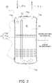
- the accumulator 28 includes a casing 71 forming an internal space IS, an inlet pipe 72, and an outlet pipe 73.
- the casing 71 mainly includes a cylindrical body 71a, a bowl-shaped upper lid 71b closing an opening above the body 71a, and a bowl-shaped lower lid 71c closing an opening below the body 71a.
- the inlet pipe 72 introduces the refrigerant that has passed through the first pipe 31a of the suction pipe 31 into the internal space IS.
- the inlet pipe 72 penetrates a periphery of the upper lid 71b.
- a tip opening 72a of the inlet pipe 72 is disposed in an upper portion of the internal space IS.
- the outlet pipe 73 of the accumulator 70 guides the gas refrigerant separated in the internal space IS to the second pipe 31b of the suction pipe 31 connected to the compressor 21.
- the outlet pipe 73 is a J-shaped pipe.
- the outlet pipe 73 penetrates the upper lid 71b and makes a U-turn in a lower portion of the internal space IS.
- the height position of an opening 73a at an upper end (tip) of the outlet pipe 73 is located in an upper portion of the internal space IS.
- An oil return hole 73b is formed in the U-turn portion of the outlet pipe 73 in the lower portion of the internal space IS.
- the oil return hole 73b is provided to return the refrigerating machine oil accumulated together with the liquid refrigerant in the lower portion of the internal space IS of the casing 71 to the compressor 21.
- a pressure equalizing hole 73c is formed in a portion of the outlet pipe 73 near the upper lid 71b.
- the outlet pipe 73 of the accumulator 70 is connected to the compressor 21 by the second pipe 31b of the suction pipe 31.
- the refrigerant connection pipes 5 and 6 are refrigerant pipes constructed on the spot when the air conditioning apparatus 1 is installed at an installation location such as a building.
- the length and pipe diameter of the refrigerant connection pipes 5 and 6 are selected according to installation conditions such as the installation location and a combination of the outdoor unit 2 and the indoor unit 4.
- part of the refrigerant circuit 10 of the indoor unit 4 is connected to part of the refrigerant circuit 10 of the outdoor unit 2 by the refrigerant connection pipes 5 and 6, constituting the refrigerant circuit 10 as a whole.
- the compressor 21, the outdoor heat exchanger 23 which functions as a radiator or evaporator for the refrigerant, the expansion valve 24, the indoor heat exchanger 41 which functions as an evaporator or radiator for the refrigerant, and the accumulator (container) 28 are connected in order.
- FIG. 3 is a control block diagram of the air conditioning apparatus 1 (refrigeration apparatus).
- the air conditioning apparatus 1 includes a control unit 8 that controls constituent devices.
- the control unit 8 is configured by connecting an outdoor control unit 38, an indoor control unit 44, and a remote control device 9 via a transmission line or a communication line.
- the outdoor control unit 38 is provided in the outdoor unit 2.
- the indoor control unit 44 is provided in the indoor unit 4.
- the remote control device 9 is provided indoors.
- the control units 38 and 44 and the remote control device 9 are connected by wire via a transmission line or a communication line, but may be wirelessly connected.
- the outdoor control unit 38 is provided in the outdoor unit 2 as described above, and mainly includes an outdoor CPU 38a, an outdoor transmission unit 38b, and an outdoor storage unit 38c.
- the outdoor control unit 38 receives detection signals such as signals from the temperature sensors 51 to 55.
- the outdoor CPU 38a is connected to the outdoor transmission unit 38b and the outdoor storage unit 38c.
- the outdoor transmission unit 38b transmits control data and the like to and from the indoor control unit 44.
- the outdoor storage unit 38c stores control data and the like.
- the outdoor CPU 38a controls constituent devices provided in the outdoor unit 2 (compressor 21, four-way switching valve 22, expansion valve 24, outdoor fan 36, and the like) while transmitting, reading, and writing control data and the like via the outdoor transmission unit 38b and the outdoor storage unit 38c.
- the indoor control unit 44 is provided in the indoor unit 4 as described above, and mainly includes an indoor CPU 44a, an indoor transmission unit 44b, an indoor storage unit 44c, and an indoor communication unit 44d.
- the indoor control unit 44 receives detection signals such as signals from the temperature sensors 56 to 58.
- the indoor CPU 44a is connected to the indoor transmission unit 44b, the indoor storage unit 44c, and the indoor communication unit 44d.
- the indoor transmission unit 44b transmits control data and the like to and from the outdoor control unit 38.
- the indoor storage unit 44c stores control data and the like.
- the indoor communication unit 44d sends and receives control data and the like to and from the remote control device 9.
- the indoor CPU 44a controls constituent devices provided in the indoor unit 4 (indoor fan 42 and the like) while transmitting, reading, writing, sending, and receiving control data and the like via the indoor transmission unit 44b, the indoor storage unit 44c, and the indoor communication unit 44d.
- the remote control device 9 is provided indoors as described above, and mainly includes a remote control CPU 91, a remote control communication unit 93, a remote control manipulation unit 94, and a remote control display unit 95.
- the remote control CPU 91 is connected to the remote control communication unit 93, the remote control manipulation unit 94, and the remote control display unit 95.
- the remote control communication unit 93 sends and receives control data and the like to and from the indoor communication unit 44d.
- the remote control manipulation unit 94 receives input such as a control command from a user.
- the remote control display unit 95 displays the operation and the like.
- the remote control CPU 91 receives input such as operation commands and control commands via the remote control manipulation unit 94, and issues control commands and the like to the indoor control unit 44 via the remote control communication unit 93 while displaying the operating state, control state, and the like on the remote control display unit 95.
- the air conditioning apparatus 1 (refrigeration apparatus) will be described with reference to FIGS. 1 and 3 .
- the air conditioning apparatus 1 executes the cooling operation and the heating operation.
- the control unit 8 When a cooling operation command is received via the remote control manipulation unit 94 of the remote control device 9 or the like, the control unit 8 sets the operating mode of the air conditioning apparatus 1 to the cooling operation. Then, the control unit 8 switches the four-way switching valve 22 to the cooling cycle state (state shown by the solid line in FIG. 1 ), drives the compressor 21 and the fans 36 and 42, and opens the expansion valve 24.
- the low-pressure refrigerant in the refrigeration cycle in the refrigerant circuit 10 is sucked into the compressor 21, compressed to high pressure in the refrigeration cycle, and then discharged.
- the high-pressure gas refrigerant discharged from the compressor 21 is sent to the outdoor heat exchanger 23 through the four-way switching valve 22.
- the high-pressure gas refrigerant sent to the outdoor heat exchanger 23 radiates heat by heat exchange with outdoor air supplied as a cooling source by the outdoor fan 36 in the outdoor heat exchanger 23, and becomes a high-pressure liquid refrigerant.
- the high-pressure liquid refrigerant that has radiated heat in the outdoor heat exchanger 23 is sent to the expansion valve 24.
- the high-pressure liquid refrigerant sent to the expansion valve 24 is decompressed by the expansion valve 24 to low pressure in the refrigeration cycle.
- the low-pressure refrigerant decompressed in the expansion valve 24 is sent to the indoor heat exchanger 41 through the liquid-side shutoff valve 26 and the liquid-refrigerant connection pipe 5.
- the low-pressure refrigerant sent to the indoor heat exchanger 41 exchanges heat with the indoor air supplied by the indoor fan 42 as a heating source to evaporate in the indoor heat exchanger 41.
- the indoor air is thus cooled and then supplied into the room, thereby cooling the room.
- the low-pressure refrigerant evaporated in the indoor heat exchanger 41 is sent to the suction pipe 31 through the gas-refrigerant connection pipe 6, the gas-side shutoff valve 27, and the four-way switching valve 22. Thereafter, the refrigerant is sucked into the compressor 21 again through the accumulator 28.
- the control unit 8 sets the operating mode of the air conditioning apparatus 1 to the heating operation. Then, the control unit 8 switches the four-way switching valve 22 to the heating cycle state (state shown by the broken line in FIG. 1 ), drives the compressor 21 and the fans 36 and 42, and opens the expansion valve 24.
- the low-pressure refrigerant in the refrigeration cycle in the refrigerant circuit 10 is sucked into the compressor 21, compressed to high pressure in the refrigeration cycle, and then discharged.
- the high-pressure gas refrigerant discharged from the compressor 21 is sent to the indoor heat exchanger 41 via the four-way switching valve 22, the gas-side shutoff valve 27, and the gas-refrigerant connection pipe 6.
- the high-pressure gas refrigerant sent to the indoor heat exchanger 41 radiates heat by heat exchange with indoor air supplied as a cooling source by the indoor fan 42 in the indoor heat exchanger 41, and becomes a high-pressure liquid refrigerant.
- the indoor air is thus heated and then supplied into the room, thereby heating the room.
- the high-pressure liquid refrigerant that has radiated heat in the indoor heat exchanger 41 is sent to the expansion valve 24 through the liquid-refrigerant connection pipe 5 and the liquid-side shutoff valve 26.
- the high-pressure liquid refrigerant sent to the expansion valve 24 is decompressed by the expansion valve 24 to low pressure in the refrigeration cycle.
- the low-pressure refrigerant decompressed in the expansion valve 24 is sent to the outdoor heat exchanger 23.
- the low-pressure liquid refrigerant sent to the outdoor heat exchanger 23 exchanges heat with the outdoor air supplied as a heating source by the outdoor fan 36 to evaporate in the outdoor heat exchanger 23.
- the low-pressure refrigerant evaporated in the outdoor heat exchanger 23 is sent to the suction pipe 31 through the four-way switching valve 22, and sucked again into the compressor 21 through the accumulator 28.
- control unit 8 executes compressor capacity control and expansion valve degree of subcooling control as basic control.
- the compressor capacity control is control to change the frequency F of the compressor 21 based on the temperature difference ⁇ Tra between the indoor temperature Tra and the indoor set temperature Trat.
- the set temperature Trat is a temperature value set via the remote control manipulation unit 94 of the remote control device 9, or the like.
- control unit 8 obtains the temperature difference ⁇ Tra by subtracting the set temperature Trat from the indoor temperature Tra.
- control unit 8 obtains the temperature difference ⁇ Tra by subtracting the indoor temperature Tra from the set temperature Trat.
- the control unit 8 Since it is required to increase the air conditioning capacity (cooling capacity or heating capacity) as refrigerating capacity when the temperature difference ⁇ Tra is positive (in other words, when the indoor temperature Tra does not reach the set temperature Trat), the control unit 8 increases the frequency F of the compressor 21. Specifically, the control unit 8 determines the change width ⁇ F of the frequency F of the compressor 21 according to the magnitude of the temperature difference ⁇ Tra to increase the frequency F of the compressor 21 by the change width ⁇ F. Since it is required to decrease the air conditioning capacity (cooling capacity or heating capacity) when the temperature difference ⁇ Tra is negative (in other words, when the indoor temperature Tra reaches the set temperature Trat), the control unit 8 decreases the frequency F of the compressor 21. Specifically, the control unit 8 determines the change width ⁇ F of the frequency F of the compressor 21 according to the magnitude of the temperature difference ⁇ Tra to decrease the frequency F of the compressor 21 by the change width ⁇ F.
- the expansion valve degree of subcooling control is control to change the opening degree MV of the expansion valve 24 based on the degree of subcooling SC of the refrigerant at an outlet of the radiator for the refrigerant. Specifically, the control unit 8 changes the opening degree MV of the expansion valve 24 such that the degree of subcooling SC becomes the target degree of subcooling SCt.
- the degree of subcooling SC is the degree of subcooling at the outlet of the outdoor heat exchanger 23 that functions as a radiator for the refrigerant in the cooling operation, and is the degree of subcooling at the outlet of the indoor heat exchanger 41 that functions as a radiator for the refrigerant in the heating operation.
- control unit 8 subtracts the refrigerant temperature Tol on the liquid side of the outdoor heat exchanger 23 from the refrigerant temperature Tom in the intermediate portion of the outdoor heat exchanger 23 to obtain the degree of subcooling SC.
- control unit 8 subtracts the temperature Trl from the temperature Trm of the indoor heat exchanger 41 to obtain the degree of subcooling SC.
- the control unit 8 increases the opening degree MV of the expansion valve 24 in order to decrease the degree of subcooling SC. Specifically, the control unit 8 determines the change width ⁇ MV of the opening degree MV of the expansion valve 24 according to the degree of subcooling difference ⁇ SC between the degree of subcooling SC and the target degree of subcooling SCt, and increases the opening degree MV of the expansion valve 24 by the change width ⁇ MV. When the degree of subcooling SC is smaller than the target degree of subcooling SCt, the control unit 8 decreases the opening degree MV of the expansion valve 24 in order to increase the degree of subcooling SC.
- control unit 8 determines the change width ⁇ MV of the opening degree MV of the expansion valve 24 according to the degree of subcooling difference ⁇ SC between the target degree of subcooling SCt and the degree of subcooling SC, and decreases the opening degree MV of the expansion valve 24 by the change width ⁇ MV.
- the oil return control is control in an oil return operation for returning the refrigerating machine oil that has flowed out from the compressor 21 to the refrigerant circuit 10 (except compressor 21) to the compressor 21.
- the compressor 21 is driven at a predetermined number of oil return revolutions for a predetermined time.
- the predetermined number of oil return revolutions is required at least to be set to the number of revolutions at which the desired amount of refrigerating machine oil out of the refrigerating machine oil that has flowed out to the refrigerant circuit 10 except the compressor 21 returns to the compressor 21 by driving the compressor 21 for a predetermined time, and to be determined as appropriate by simulation, experiment, calculation on paper, or the like.
- the predetermined number of oil return revolutions is usually set to some relatively high number of revolutions. This is to efficiently return the refrigerating machine oil in the refrigerant circuit 10 to the compressor 21.
- the control unit 8 executes the oil return operation.
- the threshold value of the integrated value of the refrigerant is set near the upper limit of the amount of discharged oil allowed for reliability of the compressor 21.
- the air conditioning apparatus 1 uses difluoromethane (R32) as a refrigerant, when the outside air temperature is low, the degree of miscibility between the refrigerant and the refrigerating machine oil, which is sealed with the refrigerant for lubrication of the compressor 21, is very small. Therefore, on the low-pressure side in the refrigeration cycle, because of a decrease in the refrigerant temperature, the degree of miscibility between the refrigerating machine oil and the refrigerant greatly decreases.
- the refrigerant and the refrigerating machine oil are separated into two layers in the accumulator 28 that becomes low pressure in the refrigeration cycle, and it becomes difficult for the refrigerating machine oil to return to the compressor 21.
- the lower portion of the internal space IS of the casing 71 tends to be filled with the liquid refrigerant and the refrigerating machine oil separated from the liquid refrigerant tends to gather in the upper portion of the internal space IS. Then, the oil return hole 73b of the outlet pipe 73 of the accumulator 28 is separated from the refrigerating machine oil, and therefore the refrigerating machine oil that has accumulated in the internal space IS of the accumulator 28 cannot be returned to the compressor 21.
- the control unit 8 executes a separation solution operation to solve the separation state.
- the separation solution control including the separation solution operation will be described with reference to the control flowchart shown in FIG. 4 .
- step S1 the control unit 8 determines whether there is an operation stop signal.
- the operation stop signal is a signal sent from the remote control device 9 to the indoor control unit 44 when a manipulation of stopping the operation of the air conditioning apparatus 1 is executed with the remote control manipulation unit 94 of the remote control device 9.
- the operation stop signal is, for example, a thermo-off signal sent from the indoor control unit 44 to the outdoor control unit 38 when the room temperature becomes higher than the indoor heating set temperature by 1°C or more.
- step S1 On determination in step S1 that there is an operation stop signal, the process proceeds to step S12, and the control unit 8 determines whether the suction temperature Ts is lower than a first threshold temperature T1.
- the suction temperature Ts is a temperature of the refrigerant in front of the accumulator 28, the temperature being detected by the suction temperature sensor 51.
- step S12 On determination in step S12 that the suction temperature Ts is equal to or higher than the first threshold temperature T1, the degree of separation between the refrigerant and the refrigerating machine oil in the accumulator 28 is within a permissible range while the compressor is stopped, and the control unit 8 stops the compressor 21 as it is (step S13).
- step S1 On determination in step S1 that there is no operation stop signal, the process proceeds to step S2, and the control unit 8 determines whether the suction temperature Ts is lower than a second threshold temperature T2.
- step S2 On determination in step S2 that the suction temperature Ts is equal to or higher than the second threshold temperature T2, the degree of separation between the refrigerant and the refrigerating machine oil in the accumulator 28 is within the permissible range while the compressor is operating, and thus the control unit 8 maintains normal control of the number of revolutions of the compressor 21 and control of the opening degree of the expansion valve 24 at that time, and returns to step S1.
- the permissible range while the compressor is stopped is different from the permissible range while the compressor is operating. Since it is preferable to continue normal control as much as possible while the compressor is operating, the permissible range while the compressor is operating is set widely.
- the permissible range while the compressor is stopped is set narrower than the permissible range while the compressor is operating in order to ensure that the refrigerating machine oil in the compressor 21 is sufficient when restarting the compressor 21. Therefore, the second threshold temperature T2 is lower than the first threshold temperature T1.
- step S2 On determination in step S2 that the suction temperature Ts is below the second threshold temperature T2 or on determination in step S12 that the suction temperature Ts is below the first threshold temperature T1, the control unit 8 proceeds to steps S3 and S4.
- steps S3 and S4 in order to alleviate and solve the separation state between the refrigerant and the refrigerating machine oil in the accumulator 28, the number of revolutions of the compressor 21 is decreased to a predetermined number of revolutions, and the opening degree of the expansion valve 24 is increased until fully opened.
- the control unit 8 executes each of the operations of steps S3 and S4 in parallel.
- step S5 the process proceeds to step S6, and the control unit 8 returns to normal control before executing steps S3 and S4 by which the opening degree of the expansion valve 24 and the number of revolutions of the compressor 21 are adjusted.
- the number of revolutions of the compressor 21 and the opening degree of the expansion valve 24 in normal control are determined as described in (5-3-1) and (5-3-2).
- step S5 can be selected from the range from 1 minute to 10 minutes, and is set in advance when the air conditioning apparatus 1 is manufactured.
- control unit 8 determines whether the refrigerant and the refrigerating machine oil are separated in the accumulator 28 based on the temperature Ts detected by the suction temperature sensor 51 (steps S2 and S12). Then, when it is detected that the refrigerant and the refrigerating machine oil are separated in the accumulator 28, the control unit 8 executes the separation solution operation (steps S3, S4, S5). In the separation solution operation, the compressor 21 is driven at a predetermined number of revolutions lower than in the oil return operation. Accordingly, the separation state of the refrigerant and the refrigerating machine oil in the internal space IS of the accumulator 28 is alleviated and solved.
- steps S12 and S2 it is determined whether the refrigerant and the refrigerating machine oil are separated in the accumulator 28 by using respective threshold values (first threshold temperature T1 and second threshold temperature T2). This determination is made by the control unit 8 based on the temperature inside the accumulator 28, here, the suction temperature Ts corresponding to the temperature.
- the control unit 8 determines whether the refrigerant and the refrigerating machine oil are separated in the accumulator 28 with reference to the graph shown in FIG. 5 .
- the graph shown in FIG. 5 is divided into a region A in an environment where the refrigerant and the refrigerating machine oil are separated, and a region B in an environment where the refrigerant and the refrigerating machine oil are not separated.
- the graph shown in FIG. 5 is a graph showing the relationship between oil concentration and two-layer separation temperature when the refrigerant is difluoromethane (R32) and the refrigerating machine oil is polyvinyl ether (PVE).
- the two-layer separation temperature is about 0°C and each threshold value is set near 0°C.
- the second threshold temperature T2 is set to -3°C and the first threshold temperature T1 is set to 0°C.
- the suction temperature sensor 51 detects the temperature of the refrigerant flowing into the accumulator 28.
- the control unit 8 controls the number of revolutions of the compressor 21 and the opening degree of the expansion valve 24.
- the control unit 8 executes the separation solution operation including steps S3 and S4.
- the control of step S3 the number of revolutions of the compressor 21 is decreased.
- the opening degree of the expansion valve 24 is set to the predetermined opening degree (fully open).
- the separation solution operation of decreasing the number of revolutions of the compressor 21 and increasing the opening degree of the expansion valve 24 is executed when the refrigerant and the refrigerating machine oil are separated inside the accumulator 28. Therefore, the pressure (low pressure value) on the suction side of the compressor 21 including the accumulator 28 can be increased. This makes it possible to change the pressure and temperature in the accumulator 28 to solve the separation state between the refrigerant and the refrigerating machine oil.
- control unit 8 fully opens the opening degree of the expansion valve 24 in the control of step S4. Therefore, since the separation solution operation is executed to fully open the opening degree of the expansion valve 24 when the refrigerant and the refrigerating machine oil are separated inside the accumulator 28, a large amount of high-temperature refrigerant flows into the accumulator 28. This allows the separation solution operation to solve the separation state between the refrigerant and the refrigerating machine oil at an early stage.
- the control unit 8 decreases the number of revolutions of the compressor 21 in the control of step S3 to set the number of revolutions of the compressor 21 to a predetermined number of revolutions.
- the control to decrease the number of revolutions of the compressor 21 to the predetermined number of revolutions is adopted instead of the control to decrease the number of revolutions a little. Therefore, the separation state between the refrigerant and the refrigerating machine oil is solved in a short time. Note that as one example, in the control of step S3, the number of revolutions of the compressor 21 is decreased to a predetermined number of revolutions in the range from 20 to 30 rpm.
- the control unit 8 executes the oil return operation separately from the separation solution operation.
- the oil return operation is an operation of returning the refrigerating machine oil staying in the refrigerant circuit 10 except the compressor 21 to the compressor 21.
- Some conventional refrigeration apparatus such as the air conditioning apparatus, also executes the oil return operation similar to the present embodiment.
- the oil return operation in which the motor of the compressor is turned at a relatively high number of revolutions, may not be preferable as an operation to solve the separation state between the refrigerant and the refrigerating machine oil inside the container such as the accumulator. Therefore, the control unit 8 of the air conditioning apparatus 1 executes the separation solution operation shown in FIG. 4 , in addition to the oil return operation, to alleviate and solve the separation between the refrigerant and the refrigerating machine oil in the accumulator 28.
- the number of revolutions of the compressor 21 is decreased to the predetermined number of revolutions. Since the compressor 21 is turned at a lower number of revolutions (predetermined number of revolutions) unlike the oil return operation, the pressure in the accumulator 28 increases and the separation state between the refrigerant and the refrigerating machine oil in the accumulator 28 is alleviated and solved at an early stage.
- the control unit 8 determines whether to execute the separation solution operation before stopping the compressor 21, based on the detection result of the suction temperature sensor 51 (see step S12 in FIG. 4 ). If the suction temperature Ts is so low that stopping the compressor 21 as it is may lead to a situation where the refrigerating machine oil in the compressor 21 is insufficient when restarting, control is executed to stop the compressor (step S13 in FIG. 4 ) after the separation solution operation is executed. When the suction temperature Ts is lower than the first threshold temperature T1 in step S12 and the separation solution operation is performed, the suction temperature Ts increases accordingly. When the determination is made again in step S12 after the separation solution operation is finished, it is determined in step S12 that the suction temperature Ts is higher than the first threshold temperature T1, and the process proceeds to step S13 to stop the compressor 21.
- the control unit 8 determines whether the refrigerant and the refrigerating machine oil are separated inside the accumulator 28 by a first criterion (first threshold temperature T1) based on the detection result of the suction temperature sensor 51. Meanwhile, when the request to stop the compressor 21 is not received, the control unit 8 determines whether the refrigerant and the refrigerating machine oil are separated inside the accumulator 28 by a second criterion (second threshold temperature T2) different from the first criterion (first threshold temperature T1) based on the detection result of the suction temperature sensor 51.
- first threshold temperature T1 first threshold temperature T1
- second threshold temperature T2 second threshold temperature T2
- the criterion for determining whether the refrigerant and the refrigerating machine oil are separated inside the accumulator 28 is changed depending on whether the request to stop the compressor 21 is received or not. This makes it possible, for example, to decrease the frequency at which the first and second control is executed when the compressor 21 is operating, and to increase the frequency at which the first and second control is executed when the compressor 21 stops.
- the embodiment determines the degree of separation between the refrigerant and the refrigerating machine oil in the accumulator 28 by using the measured value of the suction temperature sensor 51 that detects the temperature of the refrigerant flowing into the accumulator 28.
- the separation may be determined based on a plurality of parameters such as the measured value of the suction temperature sensor 51 and the evaporation temperature.
- the air conditioning apparatus 1 of the embodiment is an air conditioning apparatus that can switch between the cooling operation and the heating operation, but is not limited to this apparatus.
- the above-described separation solution operation is also effective for an air conditioning apparatus that executes only the cooling operation. When the refrigerant and the refrigerating machine oil are separated in the accumulator 28 in both the cooling operation and the heating operation, the separation solution operation is effective.
- the expansion valve 24 is fully opened in the separation solution operation (step S4 in FIG. 4 ), but is not necessarily required to be fully opened. This is because when the expansion valve 24 is fully opened, there is a disadvantage that it takes a little time to return to normal control after the separation solution operation.
- the opening degree of the expansion valve 24 in the separation solution operation is preferably 90% or more of the fully open position. This is because the liquid refrigerant held inside the heat exchanger by the expansion valve degree of subcooling control finally flows into the accumulator 28.
- the embodiment has described the air conditioning apparatus 1 that uses difluoromethane (R32) alone as a refrigerant.
- difluoromethane R32
- the above-described separation solution operation is effective as long as the mixed refrigerant separates from the refrigerating machine oil when the temperature is low.
- the above-described separation solution operation is effective as long as the mixed refrigerant separates from the refrigerating machine oil when the temperature is low.
- Patent Literature 1 JP 2016-211774 A
Landscapes
- Engineering & Computer Science (AREA)
- Physics & Mathematics (AREA)
- Mechanical Engineering (AREA)
- Thermal Sciences (AREA)
- General Engineering & Computer Science (AREA)
- Chemical & Material Sciences (AREA)
- Analytical Chemistry (AREA)
- Power Engineering (AREA)
- Air Conditioning Control Device (AREA)
Abstract
Description
- The present disclosure relates to a refrigeration apparatus, in particular to a refrigeration apparatus in which a container is disposed between an evaporator and a compressor.
- Conventionally, there has been a refrigeration apparatus including a container that temporarily stores a refrigerant returning from an evaporator to a compressor. Refrigerating machine oil is sealed in a refrigerant circuit of the refrigeration apparatus together with the refrigerant, and the refrigerant and the refrigerating machine oil may separate in the container depending on temperature and pressure conditions. For this problem, Patent Literature 1 (
Japanese Laid-Open Patent Publication No. 2016-211774 - The above-described Patent Literature 1 (
Japanese Laid-Open Patent Publication No. 2016-211774 - A refrigeration apparatus of a first aspect includes a refrigerant circuit, a detection unit, and a control unit. In the refrigerant circuit, a compressor, a radiator, an expansion valve, an evaporator, and a container are connected in order. The refrigerant flows inside the refrigerant circuit. The detection unit detects the temperature or pressure of the refrigerant. The control unit controls the number of revolutions of the compressor and the opening degree of the expansion valve. On determination that the refrigerant and a lubricating oil are separated inside the container based on a detection result of the detection unit, the control unit executes first control and second control. The first control is control to decrease the number of revolutions of the compressor. The second control sets the opening degree of the expansion valve to a predetermined opening degree.
- Here, the first and second control to decrease the number of revolutions of the compressor and set the opening degree of the expansion valve to a predetermined opening degree is executed when the refrigerant and the lubricating oil are separated inside the container. Therefore, the pressure on the suction side of the compressor including the container (hereinafter referred to as low pressure value) can be increased. This makes it possible to change the pressure and temperature in the container to solve the separation state between the refrigerant and the lubricating oil.
- The refrigeration apparatus of a second aspect is the refrigeration apparatus of the first aspect, in which in the second control, the control unit sets the opening degree of the expansion valve to an opening degree of a fully open position or 90% or more of the fully open position.
- Here, since the opening degree of the expansion valve is near the fully open position when the refrigerant and the lubricating oil are separated inside the container, a large amount of high-temperature refrigerant flows into the container. This solves the separation state of the refrigerant and the lubricating oil at an early stage.
- The refrigeration apparatus of a third aspect is the refrigeration apparatus of the first aspect or the second aspect, in which in the first control, the control unit decreases the number of revolutions of the compressor to set the number of revolutions of the compressor to a predetermined number of revolutions.
- Here, since the number of revolutions of the compressor decreases to the predetermined number of revolutions, the separation state between the refrigerant and the lubricating oil is solved at an early stage.
- The refrigeration apparatus of a fourth aspect is the refrigeration apparatus of the third aspect, in which the control unit has an oil return operation other than the first control and the second control. The oil return operation is an operation of returning the lubricating oil staying in the refrigerant circuit except the compressor to the compressor.
- The refrigeration apparatus of the fourth aspect also has the oil return operation of the conventional refrigeration apparatus. However, the oil return operation, in which the motor of the compressor is turned at a relatively high number of revolutions, may not be preferable as an operation to solve the separation state between the refrigerant and the lubricating oil inside the container. Therefore, the control unit of the refrigeration apparatus of the fourth aspect has, apart from the oil return operation, an operation to solve the separation between the refrigerant and the lubricating oil in the container by the first control and second control.
- The refrigeration apparatus of a fifth aspect is the refrigeration apparatus of the fourth aspect, in which when a condition that an integrated value of an amount of the refrigerant circulating in the refrigerant circuit exceeds a threshold value is satisfied, the control unit executes the oil return operation.
- The refrigeration apparatus of a sixth aspect is the refrigeration apparatus of the fourth aspect or the fifth aspect, in which the predetermined number of revolutions in the first control is smaller than the number of revolutions of the compressor in the oil return operation.
- Here, in contrast to the oil return operation of turning the compressor at a relatively high number of revolutions, in the first control to solve the separation between the refrigerant and the lubricating oil in the container, the number of revolutions of the compressor is decreased. Since the compressor is turned at a lower number of revolutions (predetermined number of revolutions) unlike the oil return operation, the pressure in the container increases and the separation state between the refrigerant and the lubricating oil in the container is more easily solved.
- The refrigeration apparatus of a seventh aspect is the refrigeration apparatus of any one of the first aspect to the sixth aspect, in which when a request for stopping the compressor is received, the control unit determines whether to execute the first control and the second control before stopping the compressor based on a detection result of the detection unit.
- Here, when the refrigerant and the lubricating oil are separated inside the container, the first control and the second control are executed before stopping the compressor. Therefore, the situation in which the compressor is stopped while the refrigerant and the lubricating oil are separated in the container and the compressor runs out of lubricating oil when the compressor is started again is inhibited.
- Note that the request for stopping the compressor is a stop request based on an operation stop manipulation by a user of the refrigeration apparatus, or a stop request when the request for refrigerant circulation in a user-side unit of the refrigeration apparatus is temporarily canceled. The latter stop request is, for example, a thermo-off signal in the indoor unit, which is the user-side unit of an air conditioning apparatus, when the room temperature in the cooling operation becomes less than the set temperature.
- The refrigeration apparatus of an eighth aspect is the refrigeration apparatus of any one of the first aspect to the sixth aspect, in which when a request to stop the compressor is received, the control unit determines whether the refrigerant and the lubricating oil are separated inside the container by a first criterion based on the detection result of the detection unit. When the request to stop the compressor is not received, the control unit determines whether the refrigerant and the lubricating oil are separated inside the container by a second criterion different from the first criterion based on the detection result of the detection unit.
- Here, when the request to stop the compressor is received or not, it is determined whether the refrigerant and the lubricating oil are separated inside the container based on the detection result of the detection unit. Therefore, both when the compressor is operating and when the compressor is stopped, the first control and second control to solve the separation state between the refrigerant and the lubricating oil can be executed. The criterion for determining whether the refrigerant and the lubricating oil are separated inside the container is changed depending on whether the request to stop the compressor is received or not. This makes it possible, for example, to decrease the frequency at which the first and second control is executed when the compressor is operating, and to increase the frequency at which the first and second control is executed when the compressor stops.
- The refrigeration apparatus of a ninth aspect is the refrigeration apparatus of any one of the first aspect to the eighth aspect, in which the detection unit includes a sensor. The sensor measures the temperature of the refrigerant in the container or the temperature of the refrigerant flowing through the refrigerant pipe connected to the container.
- Here, the temperature of the refrigerant in the container can be accurately detected from the measured values of the temperature sensor and/or pressure sensor.
- The refrigeration apparatus of a tenth aspect is the refrigeration apparatus of any one of the first aspect to the ninth aspect, in which the refrigerant circulating through the refrigerant circuit is R32.
- The refrigeration apparatus of an eleventh aspect is the refrigeration apparatus of any one of the first aspect to the tenth aspect, in which on determination that the refrigerant and the lubricating oil are separated inside the container from the detection result of the detection unit, the control unit executes the first control and the second control to keep operating the compressor for a predetermined period of 1 minute to 10 minutes.
-
-
FIG. 1 is a schematic configuration diagram of an air conditioning apparatus. -
FIG. 2 is a schematic configuration diagram of an accumulator. -
FIG. 3 is a control block diagram of the air conditioning apparatus. -
FIG. 4 is a flowchart of separation solution control of a refrigerant and refrigerating machine oil in the accumulator. -
FIG. 5 is a graph showing the relationship between oil concentration and a two-layer separation temperature. - Hereinafter, an air conditioning apparatus as a refrigeration apparatus will be described with reference to the drawings.
-
FIG. 1 is a schematic configuration diagram of an air conditioning apparatus 1 (refrigeration apparatus). The air conditioning apparatus 1 is an apparatus capable of cooling and heating a room of a building or the like by a vapor compression refrigeration cycle. The air conditioning apparatus 1 includes anoutdoor unit 2 and an indoor unit 4. Theoutdoor unit 2 and the indoor unit 4 are connected via a liquid-refrigerant connection pipe 5 and a gas-refrigerant connection pipe 6. Arefrigerant circuit 10 that constitutes the vapor compression refrigeration cycle of the air conditioning apparatus 1 is configured by theoutdoor unit 2 and the indoor unit 4 being connected via therefrigerant connection pipes 5 and 6. Difluoromethane (R32), which is a refrigerant, is charged in therefrigerant circuit 10. Refrigerating machine oil, which is immiscible with the refrigerant, is also charged in therefrigerant circuit 10 together with the refrigerant. - The indoor unit 4 is installed indoors and constitutes part of the
refrigerant circuit 10. The indoor unit 4 includes anindoor heat exchanger 41. - In a cooling operation, the
indoor heat exchanger 41 functions as an evaporator for a refrigerant to cool indoor air, and in a heating operation, theindoor heat exchanger 41 functions as a radiator for a refrigerant to heat indoor air. A first end of theindoor heat exchanger 41 is connected to the liquid-refrigerant connection pipe 5. A second end of theindoor heat exchanger 41 is connected to the gas-refrigerant connection pipe 6. - The indoor unit 4 includes an
indoor fan 42. Theindoor fan 42 sucks indoor air into the indoor unit 4, exchanges heat with the refrigerant in theindoor heat exchanger 41, and then supplies the air indoors as supply air. Theindoor fan 42 is, for example, a centrifugal fan, a multi-blade fan, or the like driven by anindoor fan motor 43. Theindoor fan motor 43 can change a frequency (number of revolutions) by an inverter. - The indoor unit 4 includes various sensors. The indoor unit 4 includes a liquid
pipe temperature sensor 56, anintermediate temperature sensor 57, and anindoor temperature sensor 58. The liquidpipe temperature sensor 56 detects a temperature Trl of the refrigerant in the liquid side refrigerant pipe of theindoor heat exchanger 41. Theintermediate temperature sensor 57 detects a temperature Trm of the refrigerant in an intermediate portion of theindoor heat exchanger 41. Theindoor temperature sensor 58 detects a temperature Tra of the indoor air sucked into the indoor unit 4. - The
outdoor unit 2 is installed outdoors and constitutes part of therefrigerant circuit 10. Theoutdoor unit 2 includes acompressor 21, a four-way switching valve 22, anoutdoor heat exchanger 23, anexpansion valve 24, a liquid-side shutoff valve 26, a gas-side shutoff valve 27, and anaccumulator 28. Theoutdoor unit 2 includes anoutdoor fan 36. - The
compressor 21 compresses a low-pressure refrigerant in the refrigeration cycle until the refrigerant turns into a high-pressure refrigerant. Thecompressor 21 drives a positive-displacement compression element (not shown), such as a rotary type or scroll type, to rotate by acompressor motor 21a. Here, as thecompressor 21, a rotary compressor with closed structure is used. Thecompressor motor 21a can change a frequency (number of revolutions) by an inverter. Asuction pipe 31 is connected to a suction side of thecompressor 21, and adischarge pipe 32 is connected to a discharge side. Thesuction pipe 31 connects the suction side of thecompressor 21 to afirst port 22a of the four-way switching valve 22. Thesuction pipe 31 is provided with theaccumulator 28. Thesuction pipe 31 is divided into afirst pipe 31a and asecond pipe 31b before and after theaccumulator 28. Theaccumulator 28 is a container that temporarily stores the refrigerant sucked into thecompressor 21. Theaccumulator 28 will be described in detail later with reference toFIG. 2 . Thedischarge pipe 32 is a refrigerant pipe connecting the discharge side of thecompressor 21 to asecond port 22b of the four-way switching valve 22. - The four-
way switching valve 22 switches a refrigerant flow direction in therefrigerant circuit 10. - When starting the cooling operation, the four-
way switching valve 22 switches to the cooling cycle state in which theoutdoor heat exchanger 23 functions as a radiator for the refrigerant compressed in thecompressor 21, and theindoor heat exchanger 41 functions as an evaporator for the refrigerant that has radiated heat in theoutdoor heat exchanger 23. When starting the cooling operation, the four-way switching valve 22 switches such that thesecond port 22b and athird port 22c communicate with each other, and thefirst port 22a and afourth port 22d communicate with each other. Accordingly, the discharge side of the compressor 21 (discharge pipe 32) is connected to a gas side of the outdoor heat exchanger 23 (first gas refrigerant pipe 33) (see the solid line in the four-way switching valve 22 inFIG. 1 ). Furthermore, the suction side of the compressor 21 (suction pipe 31) is connected to the gas-refrigerant connection pipe 6 side (second gas refrigerant pipe 34) (see the solid line in the four-way switching valve 22 inFIG. 1 ). - When starting the heating operation, the four-
way switching valve 22 switches to the heating cycle state in which theoutdoor heat exchanger 23 functions as an evaporator for the refrigerant that has radiated heat in theindoor heat exchanger 41, and theindoor heat exchanger 41 functions as a radiator for the refrigerant compressed in thecompressor 21. When starting the heating operation, the four-way switching valve 22 switches such that thesecond port 22b and thefourth port 22d communicate with each other, and thefirst port 22a and thethird port 22c communicate with each other. Accordingly, the discharge side of the compressor 21 (discharge pipe 32) is connected to the gas-refrigerant connection pipe 6 side (second gas refrigerant pipe 34) (see the broken line in the four-way switching valve 22 inFIG. 1 ). Furthermore, the suction side of the compressor 21 (suction pipe 31) is connected to the gas side of the outdoor heat exchanger 23 (first gas refrigerant pipe 33) (see the broken line in the four-way switching valve 22 inFIG. 1 ). The firstgas refrigerant pipe 33 is a refrigerant pipe that connects thethird port 22c of the four-way switching valve 22 to the gas side of theoutdoor heat exchanger 23. The secondgas refrigerant pipe 34 is a refrigerant pipe that connects thefourth port 22d of the four-way switching valve 22 to the gas-refrigerant connection pipe 6 side. - In the cooling operation, the
outdoor heat exchanger 23 functions as a radiator for the refrigerant whose cooling source is outdoor air. In the heating operation, theoutdoor heat exchanger 23 functions as an evaporator for the refrigerant whose heating source is outdoor air. A first end on the liquid side of theoutdoor heat exchanger 23 is connected to a liquidrefrigerant pipe 35, and a second end on the gas side is connected to the firstgas refrigerant pipe 33. The liquidrefrigerant pipe 35 is a refrigerant pipe that connects the first end on the liquid side of theoutdoor heat exchanger 23 to the liquid-refrigerant connection pipe 5. - In the cooling operation, the
expansion valve 24 decompresses the high-pressure refrigerant that has radiated heat in theoutdoor heat exchanger 23 in the refrigeration cycle to low pressure in the refrigeration cycle. In the heating operation, theexpansion valve 24 decompresses the high-pressure refrigerant that has radiated heat in theindoor heat exchanger 41 in the refrigeration cycle to low pressure in the refrigeration cycle. Theexpansion valve 24 is provided in the liquidrefrigerant pipe 35. Theexpansion valve 24 is an electric expansion valve with a changeable opening degree. - The liquid-
side shutoff valve 26 and the gas-side shutoff valve 27 are provided in connecting ports with external devices and pipes (specifically, liquid-refrigerant connection pipe 5 and gas-refrigerant connection pipe 6). The liquid-side shutoff valve 26 is provided at an end of the liquidrefrigerant pipe 35. The gas-side shutoff valve 27 is provided at an end of the secondgas refrigerant pipe 34. The liquid-side shutoff valve 26 and the gas-side shutoff valve 27 are manual valves that are opened and closed by hand. - The
outdoor fan 36 plays a role of sucking outdoor air into theoutdoor unit 2 to exchange heat with the refrigerant in theoutdoor heat exchanger 23, and then discharging the air to the outside. Theoutdoor fan 36 is a propeller fan or the like driven by anoutdoor fan motor 37. Theoutdoor fan motor 37 can change a frequency (number of revolutions) by an inverter. - The
outdoor unit 2 includes various sensors. Theoutdoor unit 2 includes asuction temperature sensor 51, adischarge temperature sensor 52, anintermediate temperature sensor 53, a liquidpipe temperature sensor 54, and an outsideair temperature sensor 55. Thesuction temperature sensor 51 detects a temperature Ts of the low-pressure refrigerant sucked into thecompressor 21 in the refrigeration cycle. Thedischarge temperature sensor 52 detects a temperature Td of the high-pressure refrigerant discharged from thecompressor 21 in the refrigeration cycle. Theintermediate temperature sensor 53 detects a temperature Tom of the refrigerant in the intermediate portion of theoutdoor heat exchanger 23. The liquidpipe temperature sensor 54 detects a temperature Tol of the refrigerant on the liquid side of theoutdoor heat exchanger 23. The outsideair temperature sensor 55 detects a temperature Toa of the outdoor air sucked into theoutdoor unit 2. - As described above, the
accumulator 28 of theoutdoor unit 2 is disposed between the suction side of thecompressor 21 and thefirst port 22a of the four-way switching valve 22. Theaccumulator 28 has a function of separating the refrigerant into gas and liquid, and storing excess refrigerant on the suction side of thecompressor 21. Theaccumulator 28 separates, into gas and liquid, the refrigerant returned from theindoor heat exchanger 41 or theoutdoor heat exchanger 23 serving as an evaporator through thefirst pipe 31a of thesuction pipe 31 connected to the four-way switching valve 22. Out of the refrigerant separated into gas and liquid, the gas refrigerant is sent to thecompressor 21. As shown inFIG. 2 , theaccumulator 28 includes acasing 71 forming an internal space IS, aninlet pipe 72, and anoutlet pipe 73. - The
casing 71 mainly includes acylindrical body 71a, a bowl-shapedupper lid 71b closing an opening above thebody 71a, and a bowl-shapedlower lid 71c closing an opening below thebody 71a. Theinlet pipe 72 introduces the refrigerant that has passed through thefirst pipe 31a of thesuction pipe 31 into the internal space IS. Theinlet pipe 72 penetrates a periphery of theupper lid 71b. Atip opening 72a of theinlet pipe 72 is disposed in an upper portion of the internal space IS. - The
outlet pipe 73 of theaccumulator 70 guides the gas refrigerant separated in the internal space IS to thesecond pipe 31b of thesuction pipe 31 connected to thecompressor 21. Theoutlet pipe 73 is a J-shaped pipe. Theoutlet pipe 73 penetrates theupper lid 71b and makes a U-turn in a lower portion of the internal space IS. The height position of anopening 73a at an upper end (tip) of theoutlet pipe 73 is located in an upper portion of the internal space IS. Anoil return hole 73b is formed in the U-turn portion of theoutlet pipe 73 in the lower portion of the internal space IS. Theoil return hole 73b is provided to return the refrigerating machine oil accumulated together with the liquid refrigerant in the lower portion of the internal space IS of thecasing 71 to thecompressor 21. Apressure equalizing hole 73c is formed in a portion of theoutlet pipe 73 near theupper lid 71b. - The
outlet pipe 73 of theaccumulator 70 is connected to thecompressor 21 by thesecond pipe 31b of thesuction pipe 31. - The
refrigerant connection pipes 5 and 6 are refrigerant pipes constructed on the spot when the air conditioning apparatus 1 is installed at an installation location such as a building. The length and pipe diameter of therefrigerant connection pipes 5 and 6 are selected according to installation conditions such as the installation location and a combination of theoutdoor unit 2 and the indoor unit 4. - As described above, part of the
refrigerant circuit 10 of the indoor unit 4 is connected to part of therefrigerant circuit 10 of theoutdoor unit 2 by therefrigerant connection pipes 5 and 6, constituting therefrigerant circuit 10 as a whole. In therefrigerant circuit 10, mainly, thecompressor 21, theoutdoor heat exchanger 23 which functions as a radiator or evaporator for the refrigerant, theexpansion valve 24, theindoor heat exchanger 41 which functions as an evaporator or radiator for the refrigerant, and the accumulator (container) 28 are connected in order. -
FIG. 3 is a control block diagram of the air conditioning apparatus 1 (refrigeration apparatus). The air conditioning apparatus 1 includes acontrol unit 8 that controls constituent devices. Thecontrol unit 8 is configured by connecting anoutdoor control unit 38, anindoor control unit 44, and aremote control device 9 via a transmission line or a communication line. Theoutdoor control unit 38 is provided in theoutdoor unit 2. Theindoor control unit 44 is provided in the indoor unit 4. Theremote control device 9 is provided indoors. Here, thecontrol units remote control device 9 are connected by wire via a transmission line or a communication line, but may be wirelessly connected. - The
outdoor control unit 38 is provided in theoutdoor unit 2 as described above, and mainly includes anoutdoor CPU 38a, anoutdoor transmission unit 38b, and anoutdoor storage unit 38c. Theoutdoor control unit 38 receives detection signals such as signals from thetemperature sensors 51 to 55. - The
outdoor CPU 38a is connected to theoutdoor transmission unit 38b and theoutdoor storage unit 38c. Theoutdoor transmission unit 38b transmits control data and the like to and from theindoor control unit 44. Theoutdoor storage unit 38c stores control data and the like. Theoutdoor CPU 38a controls constituent devices provided in the outdoor unit 2 (compressor 21, four-way switching valve 22,expansion valve 24,outdoor fan 36, and the like) while transmitting, reading, and writing control data and the like via theoutdoor transmission unit 38b and theoutdoor storage unit 38c. - The
indoor control unit 44 is provided in the indoor unit 4 as described above, and mainly includes anindoor CPU 44a, an indoor transmission unit 44b, anindoor storage unit 44c, and anindoor communication unit 44d. Theindoor control unit 44 receives detection signals such as signals from thetemperature sensors 56 to 58. - The
indoor CPU 44a is connected to the indoor transmission unit 44b, theindoor storage unit 44c, and theindoor communication unit 44d. The indoor transmission unit 44b transmits control data and the like to and from theoutdoor control unit 38. Theindoor storage unit 44c stores control data and the like. Theindoor communication unit 44d sends and receives control data and the like to and from theremote control device 9. Theindoor CPU 44a controls constituent devices provided in the indoor unit 4 (indoor fan 42 and the like) while transmitting, reading, writing, sending, and receiving control data and the like via the indoor transmission unit 44b, theindoor storage unit 44c, and theindoor communication unit 44d. - The
remote control device 9 is provided indoors as described above, and mainly includes aremote control CPU 91, a remotecontrol communication unit 93, a remotecontrol manipulation unit 94, and a remotecontrol display unit 95. - The
remote control CPU 91 is connected to the remotecontrol communication unit 93, the remotecontrol manipulation unit 94, and the remotecontrol display unit 95. The remotecontrol communication unit 93 sends and receives control data and the like to and from theindoor communication unit 44d. The remotecontrol manipulation unit 94 receives input such as a control command from a user. The remotecontrol display unit 95 displays the operation and the like. Theremote control CPU 91 receives input such as operation commands and control commands via the remotecontrol manipulation unit 94, and issues control commands and the like to theindoor control unit 44 via the remotecontrol communication unit 93 while displaying the operating state, control state, and the like on the remotecontrol display unit 95. - Next, the basic operation of the air conditioning apparatus 1 (refrigeration apparatus) will be described with reference to
FIGS. 1 and3 . As the basic operation, the air conditioning apparatus 1 executes the cooling operation and the heating operation. - When a cooling operation command is received via the remote
control manipulation unit 94 of theremote control device 9 or the like, thecontrol unit 8 sets the operating mode of the air conditioning apparatus 1 to the cooling operation. Then, thecontrol unit 8 switches the four-way switching valve 22 to the cooling cycle state (state shown by the solid line inFIG. 1 ), drives thecompressor 21 and thefans expansion valve 24. - Then, the low-pressure refrigerant in the refrigeration cycle in the
refrigerant circuit 10 is sucked into thecompressor 21, compressed to high pressure in the refrigeration cycle, and then discharged. - The high-pressure gas refrigerant discharged from the
compressor 21 is sent to theoutdoor heat exchanger 23 through the four-way switching valve 22. - The high-pressure gas refrigerant sent to the
outdoor heat exchanger 23 radiates heat by heat exchange with outdoor air supplied as a cooling source by theoutdoor fan 36 in theoutdoor heat exchanger 23, and becomes a high-pressure liquid refrigerant. - The high-pressure liquid refrigerant that has radiated heat in the
outdoor heat exchanger 23 is sent to theexpansion valve 24. The high-pressure liquid refrigerant sent to theexpansion valve 24 is decompressed by theexpansion valve 24 to low pressure in the refrigeration cycle. - The low-pressure refrigerant decompressed in the
expansion valve 24 is sent to theindoor heat exchanger 41 through the liquid-side shutoff valve 26 and the liquid-refrigerant connection pipe 5. - The low-pressure refrigerant sent to the
indoor heat exchanger 41 exchanges heat with the indoor air supplied by theindoor fan 42 as a heating source to evaporate in theindoor heat exchanger 41. The indoor air is thus cooled and then supplied into the room, thereby cooling the room. - The low-pressure refrigerant evaporated in the
indoor heat exchanger 41 is sent to thesuction pipe 31 through the gas-refrigerant connection pipe 6, the gas-side shutoff valve 27, and the four-way switching valve 22. Thereafter, the refrigerant is sucked into thecompressor 21 again through theaccumulator 28. - When a heating operation command is received via the remote
control manipulation unit 94 of theremote control device 9 or the like, thecontrol unit 8 sets the operating mode of the air conditioning apparatus 1 to the heating operation. Then, thecontrol unit 8 switches the four-way switching valve 22 to the heating cycle state (state shown by the broken line inFIG. 1 ), drives thecompressor 21 and thefans expansion valve 24. - Then, the low-pressure refrigerant in the refrigeration cycle in the
refrigerant circuit 10 is sucked into thecompressor 21, compressed to high pressure in the refrigeration cycle, and then discharged. - The high-pressure gas refrigerant discharged from the
compressor 21 is sent to theindoor heat exchanger 41 via the four-way switching valve 22, the gas-side shutoff valve 27, and the gas-refrigerant connection pipe 6. - The high-pressure gas refrigerant sent to the
indoor heat exchanger 41 radiates heat by heat exchange with indoor air supplied as a cooling source by theindoor fan 42 in theindoor heat exchanger 41, and becomes a high-pressure liquid refrigerant. The indoor air is thus heated and then supplied into the room, thereby heating the room. - The high-pressure liquid refrigerant that has radiated heat in the
indoor heat exchanger 41 is sent to theexpansion valve 24 through the liquid-refrigerant connection pipe 5 and the liquid-side shutoff valve 26. - The high-pressure liquid refrigerant sent to the
expansion valve 24 is decompressed by theexpansion valve 24 to low pressure in the refrigeration cycle. The low-pressure refrigerant decompressed in theexpansion valve 24 is sent to theoutdoor heat exchanger 23. - The low-pressure liquid refrigerant sent to the
outdoor heat exchanger 23 exchanges heat with the outdoor air supplied as a heating source by theoutdoor fan 36 to evaporate in theoutdoor heat exchanger 23. - The low-pressure refrigerant evaporated in the
outdoor heat exchanger 23 is sent to thesuction pipe 31 through the four-way switching valve 22, and sucked again into thecompressor 21 through theaccumulator 28. - In the above-described basic operation (cooling operation and heating operation), the
control unit 8 executes compressor capacity control and expansion valve degree of subcooling control as basic control. - The compressor capacity control is control to change the frequency F of the
compressor 21 based on the temperature difference ΔTra between the indoor temperature Tra and the indoor set temperature Trat. The set temperature Trat is a temperature value set via the remotecontrol manipulation unit 94 of theremote control device 9, or the like. - In the cooling operation, the
control unit 8 obtains the temperature difference ΔTra by subtracting the set temperature Trat from the indoor temperature Tra. In the heating operation, thecontrol unit 8 obtains the temperature difference ΔTra by subtracting the indoor temperature Tra from the set temperature Trat. - Since it is required to increase the air conditioning capacity (cooling capacity or heating capacity) as refrigerating capacity when the temperature difference ΔTra is positive (in other words, when the indoor temperature Tra does not reach the set temperature Trat), the
control unit 8 increases the frequency F of thecompressor 21. Specifically, thecontrol unit 8 determines the change width ΔF of the frequency F of thecompressor 21 according to the magnitude of the temperature difference ΔTra to increase the frequency F of thecompressor 21 by the change width ΔF. Since it is required to decrease the air conditioning capacity (cooling capacity or heating capacity) when the temperature difference ΔTra is negative (in other words, when the indoor temperature Tra reaches the set temperature Trat), thecontrol unit 8 decreases the frequency F of thecompressor 21. Specifically, thecontrol unit 8 determines the change width ΔF of the frequency F of thecompressor 21 according to the magnitude of the temperature difference ΔTra to decrease the frequency F of thecompressor 21 by the change width ΔF. - The expansion valve degree of subcooling control is control to change the opening degree MV of the
expansion valve 24 based on the degree of subcooling SC of the refrigerant at an outlet of the radiator for the refrigerant. Specifically, thecontrol unit 8 changes the opening degree MV of theexpansion valve 24 such that the degree of subcooling SC becomes the target degree of subcooling SCt. The degree of subcooling SC is the degree of subcooling at the outlet of theoutdoor heat exchanger 23 that functions as a radiator for the refrigerant in the cooling operation, and is the degree of subcooling at the outlet of theindoor heat exchanger 41 that functions as a radiator for the refrigerant in the heating operation. - In the cooling operation, the
control unit 8 subtracts the refrigerant temperature Tol on the liquid side of theoutdoor heat exchanger 23 from the refrigerant temperature Tom in the intermediate portion of theoutdoor heat exchanger 23 to obtain the degree of subcooling SC. In the heating operation, thecontrol unit 8 subtracts the temperature Trl from the temperature Trm of theindoor heat exchanger 41 to obtain the degree of subcooling SC. - When the degree of subcooling SC is greater than the target degree of subcooling SCt, the
control unit 8 increases the opening degree MV of theexpansion valve 24 in order to decrease the degree of subcooling SC. Specifically, thecontrol unit 8 determines the change width ΔMV of the opening degree MV of theexpansion valve 24 according to the degree of subcooling difference ΔSC between the degree of subcooling SC and the target degree of subcooling SCt, and increases the opening degree MV of theexpansion valve 24 by the change width ΔMV. When the degree of subcooling SC is smaller than the target degree of subcooling SCt, thecontrol unit 8 decreases the opening degree MV of theexpansion valve 24 in order to increase the degree of subcooling SC. Specifically, thecontrol unit 8 determines the change width ΔMV of the opening degree MV of theexpansion valve 24 according to the degree of subcooling difference ΔSC between the target degree of subcooling SCt and the degree of subcooling SC, and decreases the opening degree MV of theexpansion valve 24 by the change width ΔMV. - The oil return control is control in an oil return operation for returning the refrigerating machine oil that has flowed out from the
compressor 21 to the refrigerant circuit 10 (except compressor 21) to thecompressor 21. In the oil return operation, thecompressor 21 is driven at a predetermined number of oil return revolutions for a predetermined time. - Note that the predetermined number of oil return revolutions is required at least to be set to the number of revolutions at which the desired amount of refrigerating machine oil out of the refrigerating machine oil that has flowed out to the
refrigerant circuit 10 except thecompressor 21 returns to thecompressor 21 by driving thecompressor 21 for a predetermined time, and to be determined as appropriate by simulation, experiment, calculation on paper, or the like. The predetermined number of oil return revolutions is usually set to some relatively high number of revolutions. This is to efficiently return the refrigerating machine oil in therefrigerant circuit 10 to thecompressor 21. - When the condition that the amount of refrigerant circulating in the
refrigerant circuit 10 exceeds a threshold value is satisfied, the amount being integrated after the previous oil return operation, thecontrol unit 8 executes the oil return operation. The threshold value of the integrated value of the refrigerant is set near the upper limit of the amount of discharged oil allowed for reliability of thecompressor 21. - Since the air conditioning apparatus 1 uses difluoromethane (R32) as a refrigerant, when the outside air temperature is low, the degree of miscibility between the refrigerant and the refrigerating machine oil, which is sealed with the refrigerant for lubrication of the
compressor 21, is very small. Therefore, on the low-pressure side in the refrigeration cycle, because of a decrease in the refrigerant temperature, the degree of miscibility between the refrigerating machine oil and the refrigerant greatly decreases. The refrigerant and the refrigerating machine oil are separated into two layers in theaccumulator 28 that becomes low pressure in the refrigeration cycle, and it becomes difficult for the refrigerating machine oil to return to thecompressor 21. For example, in the heating operation when the outside air temperature is low, as shown inFIG. 2 , the lower portion of the internal space IS of thecasing 71 tends to be filled with the liquid refrigerant and the refrigerating machine oil separated from the liquid refrigerant tends to gather in the upper portion of the internal space IS. Then, theoil return hole 73b of theoutlet pipe 73 of theaccumulator 28 is separated from the refrigerating machine oil, and therefore the refrigerating machine oil that has accumulated in the internal space IS of theaccumulator 28 cannot be returned to thecompressor 21. In other words, since the amount of liquid refrigerant increases around theoil return hole 73b of theoutlet pipe 73, the amount of refrigerating machine oil sucked from theoil return hole 73b decreases, and a sufficient amount of refrigerating machine oil cannot be returned to thecompressor 21. - In view of this, when the refrigerant and the refrigerating machine oil are separated in the
accumulator 28, thecontrol unit 8 executes a separation solution operation to solve the separation state. Hereinafter, the separation solution control including the separation solution operation will be described with reference to the control flowchart shown inFIG. 4 . - In step S1, the
control unit 8 determines whether there is an operation stop signal. The operation stop signal is a signal sent from theremote control device 9 to theindoor control unit 44 when a manipulation of stopping the operation of the air conditioning apparatus 1 is executed with the remotecontrol manipulation unit 94 of theremote control device 9. The operation stop signal is, for example, a thermo-off signal sent from theindoor control unit 44 to theoutdoor control unit 38 when the room temperature becomes higher than the indoor heating set temperature by 1°C or more. - On determination in step S1 that there is an operation stop signal, the process proceeds to step S12, and the
control unit 8 determines whether the suction temperature Ts is lower than a first threshold temperature T1. The suction temperature Ts is a temperature of the refrigerant in front of theaccumulator 28, the temperature being detected by thesuction temperature sensor 51. - On determination in step S12 that the suction temperature Ts is equal to or higher than the first threshold temperature T1, the degree of separation between the refrigerant and the refrigerating machine oil in the
accumulator 28 is within a permissible range while the compressor is stopped, and thecontrol unit 8 stops thecompressor 21 as it is (step S13). - On determination in step S1 that there is no operation stop signal, the process proceeds to step S2, and the
control unit 8 determines whether the suction temperature Ts is lower than a second threshold temperature T2. - On determination in step S2 that the suction temperature Ts is equal to or higher than the second threshold temperature T2, the degree of separation between the refrigerant and the refrigerating machine oil in the
accumulator 28 is within the permissible range while the compressor is operating, and thus thecontrol unit 8 maintains normal control of the number of revolutions of thecompressor 21 and control of the opening degree of theexpansion valve 24 at that time, and returns to step S1. - Note that regarding the degree of separation between the refrigerant and the refrigerating machine oil in the
accumulator 28, the permissible range while the compressor is stopped is different from the permissible range while the compressor is operating. Since it is preferable to continue normal control as much as possible while the compressor is operating, the permissible range while the compressor is operating is set widely. The permissible range while the compressor is stopped is set narrower than the permissible range while the compressor is operating in order to ensure that the refrigerating machine oil in thecompressor 21 is sufficient when restarting thecompressor 21. Therefore, the second threshold temperature T2 is lower than the first threshold temperature T1. - On determination in step S2 that the suction temperature Ts is below the second threshold temperature T2 or on determination in step S12 that the suction temperature Ts is below the first threshold temperature T1, the
control unit 8 proceeds to steps S3 and S4. In steps S3 and S4, in order to alleviate and solve the separation state between the refrigerant and the refrigerating machine oil in theaccumulator 28, the number of revolutions of thecompressor 21 is decreased to a predetermined number of revolutions, and the opening degree of theexpansion valve 24 is increased until fully opened. Thecontrol unit 8 executes each of the operations of steps S3 and S4 in parallel. - Thereafter, after waiting for a certain period of time (step S5), the process proceeds to step S6, and the
control unit 8 returns to normal control before executing steps S3 and S4 by which the opening degree of theexpansion valve 24 and the number of revolutions of thecompressor 21 are adjusted. The number of revolutions of thecompressor 21 and the opening degree of theexpansion valve 24 in normal control are determined as described in (5-3-1) and (5-3-2). - Note that the certain period of time in step S5 can be selected from the range from 1 minute to 10 minutes, and is set in advance when the air conditioning apparatus 1 is manufactured.
- As described above, the
control unit 8 determines whether the refrigerant and the refrigerating machine oil are separated in theaccumulator 28 based on the temperature Ts detected by the suction temperature sensor 51 (steps S2 and S12). Then, when it is detected that the refrigerant and the refrigerating machine oil are separated in theaccumulator 28, thecontrol unit 8 executes the separation solution operation (steps S3, S4, S5). In the separation solution operation, thecompressor 21 is driven at a predetermined number of revolutions lower than in the oil return operation. Accordingly, the separation state of the refrigerant and the refrigerating machine oil in the internal space IS of theaccumulator 28 is alleviated and solved. - In steps S12 and S2, it is determined whether the refrigerant and the refrigerating machine oil are separated in the
accumulator 28 by using respective threshold values (first threshold temperature T1 and second threshold temperature T2). This determination is made by thecontrol unit 8 based on the temperature inside theaccumulator 28, here, the suction temperature Ts corresponding to the temperature. - The
control unit 8 determines whether the refrigerant and the refrigerating machine oil are separated in theaccumulator 28 with reference to the graph shown inFIG. 5 . The graph shown inFIG. 5 is divided into a region A in an environment where the refrigerant and the refrigerating machine oil are separated, and a region B in an environment where the refrigerant and the refrigerating machine oil are not separated. The graph shown inFIG. 5 is a graph showing the relationship between oil concentration and two-layer separation temperature when the refrigerant is difluoromethane (R32) and the refrigerating machine oil is polyvinyl ether (PVE). For example, when the oil concentration is 25 wt%, the two-layer separation temperature is about 0°C and each threshold value is set near 0°C. For example, the second threshold temperature T2 is set to -3°C and the first threshold temperature T1 is set to 0°C. - Note that in the separation solution operation, a decrease in the number of revolutions of the
compressor 21 and an increase in the opening degree of theexpansion valve 24 lead to an increase in the pressure in theaccumulator 28 and an increase in the temperature of the refrigerant. With this configuration, even if the refrigerant and the refrigerating machine oil are separated in theaccumulator 28, the temperature of the refrigerant increases to exceed the two-layer separation temperature shown inFIG. 5 , alleviating and solving the separation state. - Next, features of the air conditioning apparatus 1 (refrigeration apparatus) will be described.
- (6-1)
In the air conditioning apparatus 1, thesuction temperature sensor 51 detects the temperature of the refrigerant flowing into theaccumulator 28. Thecontrol unit 8 controls the number of revolutions of thecompressor 21 and the opening degree of theexpansion valve 24. On determination that the refrigerant and the refrigerating machine oil (lubricating oil) are separated inside theaccumulator 28 based on the detection result of thesuction temperature sensor 51, thecontrol unit 8 executes the separation solution operation including steps S3 and S4. In the control of step S3, the number of revolutions of thecompressor 21 is decreased. In the control of step S4, the opening degree of theexpansion valve 24 is set to the predetermined opening degree (fully open). - Here, the separation solution operation of decreasing the number of revolutions of the
compressor 21 and increasing the opening degree of theexpansion valve 24 is executed when the refrigerant and the refrigerating machine oil are separated inside theaccumulator 28. Therefore, the pressure (low pressure value) on the suction side of thecompressor 21 including theaccumulator 28 can be increased. This makes it possible to change the pressure and temperature in theaccumulator 28 to solve the separation state between the refrigerant and the refrigerating machine oil. - (6-2)
In the air conditioning apparatus 1, thecontrol unit 8 fully opens the opening degree of theexpansion valve 24 in the control of step S4. Therefore, since the separation solution operation is executed to fully open the opening degree of theexpansion valve 24 when the refrigerant and the refrigerating machine oil are separated inside theaccumulator 28, a large amount of high-temperature refrigerant flows into theaccumulator 28. This allows the separation solution operation to solve the separation state between the refrigerant and the refrigerating machine oil at an early stage. - (6-3)
In the air conditioning apparatus 1, thecontrol unit 8 decreases the number of revolutions of thecompressor 21 in the control of step S3 to set the number of revolutions of thecompressor 21 to a predetermined number of revolutions. Here, the control to decrease the number of revolutions of thecompressor 21 to the predetermined number of revolutions is adopted instead of the control to decrease the number of revolutions a little. Therefore, the separation state between the refrigerant and the refrigerating machine oil is solved in a short time. Note that as one example, in the control of step S3, the number of revolutions of thecompressor 21 is decreased to a predetermined number of revolutions in the range from 20 to 30 rpm. - (6-4)
In the air conditioning apparatus 1, thecontrol unit 8 executes the oil return operation separately from the separation solution operation. As described above, the oil return operation is an operation of returning the refrigerating machine oil staying in therefrigerant circuit 10 except thecompressor 21 to thecompressor 21. - Some conventional refrigeration apparatus, such as the air conditioning apparatus, also executes the oil return operation similar to the present embodiment. However, the oil return operation, in which the motor of the compressor is turned at a relatively high number of revolutions, may not be preferable as an operation to solve the separation state between the refrigerant and the refrigerating machine oil inside the container such as the accumulator. Therefore, the
control unit 8 of the air conditioning apparatus 1 executes the separation solution operation shown inFIG. 4 , in addition to the oil return operation, to alleviate and solve the separation between the refrigerant and the refrigerating machine oil in theaccumulator 28. - Note that, in contrast to the oil return operation of turning the
compressor 21 at a relatively high number of revolutions, in the separation solution operation to solve the separation between the refrigerant and the refrigerating machine oil in theaccumulator 28, the number of revolutions of thecompressor 21 is decreased to the predetermined number of revolutions. Since thecompressor 21 is turned at a lower number of revolutions (predetermined number of revolutions) unlike the oil return operation, the pressure in theaccumulator 28 increases and the separation state between the refrigerant and the refrigerating machine oil in theaccumulator 28 is alleviated and solved at an early stage. - (6-5)
In the air conditioning apparatus 1, when the request to stop thecompressor 21 is received, thecontrol unit 8 determines whether to execute the separation solution operation before stopping thecompressor 21, based on the detection result of the suction temperature sensor 51 (see step S12 inFIG. 4 ). If the suction temperature Ts is so low that stopping thecompressor 21 as it is may lead to a situation where the refrigerating machine oil in thecompressor 21 is insufficient when restarting, control is executed to stop the compressor (step S13 inFIG. 4 ) after the separation solution operation is executed. When the suction temperature Ts is lower than the first threshold temperature T1 in step S12 and the separation solution operation is performed, the suction temperature Ts increases accordingly. When the determination is made again in step S12 after the separation solution operation is finished, it is determined in step S12 that the suction temperature Ts is higher than the first threshold temperature T1, and the process proceeds to step S13 to stop thecompressor 21. - Here, the situation in which the
compressor 21 is stopped while the refrigerant and the refrigerating machine oil are separated in theaccumulator 28 and thecompressor 21 runs out of refrigerating machine oil when thecompressor 21 is started again is inhibited. - (6-6)
In the air conditioning apparatus 1, when the request to stop thecompressor 21 is received, thecontrol unit 8 determines whether the refrigerant and the refrigerating machine oil are separated inside theaccumulator 28 by a first criterion (first threshold temperature T1) based on the detection result of thesuction temperature sensor 51. Meanwhile, when the request to stop thecompressor 21 is not received, thecontrol unit 8 determines whether the refrigerant and the refrigerating machine oil are separated inside theaccumulator 28 by a second criterion (second threshold temperature T2) different from the first criterion (first threshold temperature T1) based on the detection result of thesuction temperature sensor 51. - Here, both when the request to stop the
compressor 21 is received and not received, it is determined whether the refrigerant and the refrigerating machine oil are separated inside theaccumulator 28. Therefore, both when thecompressor 21 is operating and when thecompressor 21 is stopped, the separation solution operation for solving the separation state between the refrigerant and the refrigerating machine oil can be executed. The criterion for determining whether the refrigerant and the refrigerating machine oil are separated inside theaccumulator 28 is changed depending on whether the request to stop thecompressor 21 is received or not. This makes it possible, for example, to decrease the frequency at which the first and second control is executed when thecompressor 21 is operating, and to increase the frequency at which the first and second control is executed when thecompressor 21 stops. - (7-1)
The embodiment determines the degree of separation between the refrigerant and the refrigerating machine oil in theaccumulator 28 by using the measured value of thesuction temperature sensor 51 that detects the temperature of the refrigerant flowing into theaccumulator 28. - However, instead of this, it is also possible to install a sensor that can directly measure the temperature inside the
accumulator 28 and use the measured value of the sensor. - It is also possible to attach a temperature sensor to the outer peripheral surface of the
accumulator 28, or to attach a temperature sensor to a pipe downstream of theaccumulator 28. - Furthermore, it is possible to install a pressure sensor that measures the pressure of the refrigerant in the
accumulator 28 or around theaccumulator 28 instead of the temperature sensor, and to calculate the temperature of the refrigerant in theaccumulator 28 from the measured value. - Instead of determining the degree of separation of the refrigerant and refrigerating machine oil in the
accumulator 28 from the measured values of one sensor alone, the separation may be determined based on a plurality of parameters such as the measured value of thesuction temperature sensor 51 and the evaporation temperature. - (7-2)
The air conditioning apparatus 1 of the embodiment is an air conditioning apparatus that can switch between the cooling operation and the heating operation, but is not limited to this apparatus. The above-described separation solution operation is also effective for an air conditioning apparatus that executes only the cooling operation. When the refrigerant and the refrigerating machine oil are separated in theaccumulator 28 in both the cooling operation and the heating operation, the separation solution operation is effective. - (7-3)
In the embodiment, theexpansion valve 24 is fully opened in the separation solution operation (step S4 inFIG. 4 ), but is not necessarily required to be fully opened. This is because when theexpansion valve 24 is fully opened, there is a disadvantage that it takes a little time to return to normal control after the separation solution operation. However, the opening degree of theexpansion valve 24 in the separation solution operation is preferably 90% or more of the fully open position. This is because the liquid refrigerant held inside the heat exchanger by the expansion valve degree of subcooling control finally flows into theaccumulator 28. - (7-4)
The embodiment has described the air conditioning apparatus 1 that uses difluoromethane (R32) alone as a refrigerant. However, even if a mixed refrigerant containing difluoromethane is used, the above-described separation solution operation is effective as long as the mixed refrigerant separates from the refrigerating machine oil when the temperature is low. Even if a refrigerant that does not contain difluoromethane is used, the above-described separation solution operation is effective as long as the mixed refrigerant separates from the refrigerating machine oil when the temperature is low. - (7-5)
The embodiment of the present disclosure has been described above. It will be understood that various changes to modes and details can be made without departing from the spirit and scope of the present disclosure recited in the claims. -
- 1: air conditioning apparatus (refrigeration apparatus)
- 8: control unit
- 10: refrigerant circuit
- 21: compressor
- 23: outdoor heat exchanger
- 24: expansion valve
- 28: accumulator (container)
- 41: indoor heat exchanger
- 51: suction temperature sensor (detection unit)
- S3: control step of separation solution operation (first control)
- S4: control step of separation solution operation (second control)
- Patent Literature 1:
JP 2016-211774 A
Claims (11)
- A refrigeration apparatus (1) comprising:a refrigerant circuit (10) in which a compressor (21), a radiator (23, 41), an expansion valve (24), an evaporator (41, 23), and a container (28) are connected in order, and a refrigerant flows therein;a detection unit (51) configured to detect a temperature or pressure of the refrigerant; anda control unit (8) configured to control a number of revolutions of the compressor and an opening degree of the expansion valve,wherein on determination that the refrigerant and a lubricating oil are separated inside the container based on a detection result of the detection unit,the control unit executes first control (S3) to decrease the number of revolutions of the compressor, andexecutes second control (S4) to set the opening degree of the expansion valve to a predetermined opening degree.
- The refrigeration apparatus according to claim 1, wherein
in the second control, the control unit sets the opening degree of the expansion valve to an opening degree of a fully open position or 90% or more of the fully open position. - The refrigeration apparatus according to claim 1 or 2, wherein
in the first control, the control unit decreases the number of revolutions of the compressor to set the number of revolutions of the compressor to a predetermined number of revolutions. - The refrigeration apparatus according to claim 3, wherein
the control unit has an oil return operation to return the lubricating oil staying in the refrigerant circuit except the compressor to the compressor. - The refrigeration apparatus according to claim 4, wherein
when a condition that an integrated value of an amount of the refrigerant circulating in the refrigerant circuit exceeds a threshold value is satisfied, the control unit executes the oil return operation. - The refrigeration apparatus according to claim 4 or 5, wherein
the predetermined number of revolutions in the first control is smaller than the number of revolutions of the compressor in the oil return operation. - The refrigeration apparatus according to any one of claims 1 to 6, wherein
when a request to stop the compressor is received, the control unit determines whether to execute the first control and the second control before stopping the compressor based on the detection result of the detection unit. - The refrigeration apparatus according to any one of claims 1 to 6, whereinwhen a request to stop the compressor is received, the control unit determines whether the refrigerant and the lubricating oil are separated inside the container by a first criterion based on the detection result of the detection unit, andwhen the request to stop the compressor is not received, the control unit determines whether the refrigerant and the lubricating oil are separated inside the container by a second criterion different from the first criterion based on the detection result of the detection unit.
- The refrigeration apparatus according to any one of claims 1 to 8, wherein
the detection unit includes a sensor configured to measure a temperature of the refrigerant in the container or a temperature of the refrigerant flowing through a refrigerant pipe connected to the container. - The refrigeration apparatus according to any one of claims 1 to 9, wherein
the refrigerant circulating through the refrigerant circuit is R32. - The refrigeration apparatus according to any one of claims 1 to 10, wherein
on determination that the refrigerant and the lubricating oil are separated inside the container from the detection result of the detection unit, the control unit executes the first control and the second control to keep operating the compressor for a predetermined period from 1 minute to 10 minutes.
Applications Claiming Priority (2)
| Application Number | Priority Date | Filing Date | Title |
|---|---|---|---|
| JP2019199258A JP6828790B1 (en) | 2019-10-31 | 2019-10-31 | Refrigeration equipment |
| PCT/JP2020/039918 WO2021085330A1 (en) | 2019-10-31 | 2020-10-23 | Refrigeration device |
Publications (3)
| Publication Number | Publication Date |
|---|---|
| EP4053477A1 true EP4053477A1 (en) | 2022-09-07 |
| EP4053477A4 EP4053477A4 (en) | 2022-12-07 |
| EP4053477B1 EP4053477B1 (en) | 2024-12-25 |
Family
ID=74529591
Family Applications (1)
| Application Number | Title | Priority Date | Filing Date |
|---|---|---|---|
| EP20883120.6A Active EP4053477B1 (en) | 2019-10-31 | 2020-10-23 | Refrigeration device |
Country Status (6)
| Country | Link |
|---|---|
| US (1) | US11828510B2 (en) |
| EP (1) | EP4053477B1 (en) |
| JP (1) | JP6828790B1 (en) |
| CN (1) | CN114585868B (en) |
| ES (1) | ES3008717T3 (en) |
| WO (1) | WO2021085330A1 (en) |
Families Citing this family (3)
| Publication number | Priority date | Publication date | Assignee | Title |
|---|---|---|---|---|
| WO2021050468A1 (en) * | 2019-09-13 | 2021-03-18 | Carrier Corporation | Hvac unit with expansion device |
| JP7507402B2 (en) * | 2020-09-28 | 2024-06-28 | パナソニックIpマネジメント株式会社 | Air Conditioning Equipment |
| JP2026056173A (en) * | 2024-09-19 | 2026-04-01 | パナソニックIpマネジメント株式会社 | Refrigeration cycle equipment |
Family Cites Families (21)
| Publication number | Priority date | Publication date | Assignee | Title |
|---|---|---|---|---|
| JPS6213952A (en) * | 1985-07-11 | 1987-01-22 | Sharp Corp | Air conditioner |
| JP3641850B2 (en) * | 1995-07-05 | 2005-04-27 | ダイキン工業株式会社 | refrigerator |
| JP2000018739A (en) * | 1998-06-26 | 2000-01-18 | Matsushita Refrig Co Ltd | Air conditioner |
| JP2002221369A (en) * | 2001-01-22 | 2002-08-09 | Matsushita Electric Ind Co Ltd | Refrigeration device control method and control device |
| JP2003026418A (en) * | 2001-07-11 | 2003-01-29 | Ube Material Industries Ltd | Manufacturing method of hydrotalcite |
| JP5484930B2 (en) * | 2010-01-25 | 2014-05-07 | 三菱重工業株式会社 | Air conditioner |
| US9163864B2 (en) * | 2010-03-29 | 2015-10-20 | Mitsubishi Electric Corporation | Air-conditioning apparatus with oil return in a transcritical cycle |
| JP5403095B2 (en) * | 2011-12-20 | 2014-01-29 | ダイキン工業株式会社 | Refrigeration equipment |
| JP5895683B2 (en) * | 2012-04-24 | 2016-03-30 | ダイキン工業株式会社 | Refrigeration equipment |
| JP2015064128A (en) | 2013-09-24 | 2015-04-09 | ダイキン工業株式会社 | Accumulator and refrigeration equipment |
| JP2015092123A (en) * | 2013-11-08 | 2015-05-14 | ダイキン工業株式会社 | Refrigerator |
| US10753660B2 (en) * | 2015-01-23 | 2020-08-25 | Mitsubishi Electric Corporation | Air-conditioning apparatus |
| JP6028817B2 (en) * | 2015-01-30 | 2016-11-24 | ダイキン工業株式会社 | Air conditioner |
| WO2016157282A1 (en) * | 2015-03-27 | 2016-10-06 | 三菱電機株式会社 | Refrigeration cycle apparatus |
| JP6826808B2 (en) * | 2015-05-07 | 2021-02-10 | ダイキン工業株式会社 | Refrigeration equipment |
| JP6601307B2 (en) | 2016-04-26 | 2019-11-06 | 株式会社デンソー | Refrigeration cycle equipment |
| JP6540666B2 (en) * | 2016-11-24 | 2019-07-10 | ダイキン工業株式会社 | Refrigeration system |
| JP6945139B2 (en) * | 2017-05-26 | 2021-10-06 | パナソニックIpマネジメント株式会社 | Refrigeration cycle system, outdoor unit, control unit |
| WO2019087401A1 (en) * | 2017-11-06 | 2019-05-09 | ダイキン工業株式会社 | Air conditioning device |
| CN109059211B (en) * | 2018-07-24 | 2021-05-07 | 苏州艾尔智科变频科技有限公司 | Shutdown control method and controller for variable frequency system with enhanced vapor injection |
| CN109282524B (en) * | 2018-09-11 | 2019-12-13 | 青岛海信日立空调系统有限公司 | Method and device for controlling oil return of compressor |
-
2019
- 2019-10-31 JP JP2019199258A patent/JP6828790B1/en active Active
-
2020
- 2020-10-23 CN CN202080073978.4A patent/CN114585868B/en active Active
- 2020-10-23 ES ES20883120T patent/ES3008717T3/en active Active
- 2020-10-23 WO PCT/JP2020/039918 patent/WO2021085330A1/en not_active Ceased
- 2020-10-23 EP EP20883120.6A patent/EP4053477B1/en active Active
-
2022
- 2022-03-31 US US17/709,842 patent/US11828510B2/en active Active
Also Published As
| Publication number | Publication date |
|---|---|
| WO2021085330A1 (en) | 2021-05-06 |
| EP4053477B1 (en) | 2024-12-25 |
| JP2021071258A (en) | 2021-05-06 |
| CN114585868A (en) | 2022-06-03 |
| US20220221210A1 (en) | 2022-07-14 |
| EP4053477A4 (en) | 2022-12-07 |
| US11828510B2 (en) | 2023-11-28 |
| CN114585868B (en) | 2023-07-25 |
| JP6828790B1 (en) | 2021-02-10 |
| ES3008717T3 (en) | 2025-03-24 |
Similar Documents
| Publication | Publication Date | Title |
|---|---|---|
| EP3604980B1 (en) | A refrigeration apparatus | |
| US11828510B2 (en) | Refrigeration apparatus | |
| EP3604982B1 (en) | Indoor unit of refrigeration device | |
| EP3026371B1 (en) | Refrigeration cycle apparatus | |
| CN101949570B (en) | Starting control method of direct-current variable-frequency free-trailing air conditioner | |
| US8033123B2 (en) | Air conditioner | |
| CN107429949B (en) | Refrigeration cycle device | |
| CN102725598B (en) | Heat pump system | |
| CN112840164A (en) | Air conditioning device, management device and refrigerant communication pipe | |
| CN102869929B (en) | Heat pump system | |
| EP3581855A1 (en) | Air conditioning device | |
| KR20070032683A (en) | Air conditioner | |
| EP3546850A1 (en) | Refrigeration device | |
| EP2865970A1 (en) | Freezer | |
| WO2017221300A1 (en) | Air conditioner | |
| JP4315585B2 (en) | Air conditioner | |
| JP6826808B2 (en) | Refrigeration equipment | |
| JP2012145251A (en) | Heat pump device | |
| EP2863150B1 (en) | Refrigeration device | |
| CN110023693A (en) | refrigeration unit | |
| JP2006118788A (en) | Air conditioner | |
| EP4644805A1 (en) | Refrigerant leak determination method and refrigeration cycle device | |
| JP2006125665A (en) | Air conditioner | |
| CN116753608A (en) | air conditioning equipment | |
| JP2021071225A (en) | Refrigeration cycle device |
Legal Events
| Date | Code | Title | Description |
|---|---|---|---|
| STAA | Information on the status of an ep patent application or granted ep patent |
Free format text: STATUS: THE INTERNATIONAL PUBLICATION HAS BEEN MADE |
|
| PUAI | Public reference made under article 153(3) epc to a published international application that has entered the european phase |
Free format text: ORIGINAL CODE: 0009012 |
|
| STAA | Information on the status of an ep patent application or granted ep patent |
Free format text: STATUS: REQUEST FOR EXAMINATION WAS MADE |
|
| 17P | Request for examination filed |
Effective date: 20220517 |
|
| AK | Designated contracting states |
Kind code of ref document: A1 Designated state(s): AL AT BE BG CH CY CZ DE DK EE ES FI FR GB GR HR HU IE IS IT LI LT LU LV MC MK MT NL NO PL PT RO RS SE SI SK SM TR |
|
| A4 | Supplementary search report drawn up and despatched |
Effective date: 20221109 |
|
| RIC1 | Information provided on ipc code assigned before grant |
Ipc: F25B 13/00 20060101ALI20221103BHEP Ipc: F25B 31/00 20060101ALI20221103BHEP Ipc: F25B 1/00 20060101ALI20221103BHEP Ipc: F25B 49/02 20060101ALI20221103BHEP Ipc: F25B 43/02 20060101ALI20221103BHEP Ipc: F25B 43/00 20060101AFI20221103BHEP |
|
| RAP3 | Party data changed (applicant data changed or rights of an application transferred) |
Owner name: DAIKIN INDUSTRIES, LTD. |
|
| DAV | Request for validation of the european patent (deleted) | ||
| DAX | Request for extension of the european patent (deleted) | ||
| P01 | Opt-out of the competence of the unified patent court (upc) registered |
Effective date: 20230525 |
|
| STAA | Information on the status of an ep patent application or granted ep patent |
Free format text: STATUS: EXAMINATION IS IN PROGRESS |
|
| 17Q | First examination report despatched |
Effective date: 20230726 |
|
| GRAP | Despatch of communication of intention to grant a patent |
Free format text: ORIGINAL CODE: EPIDOSNIGR1 |
|
| STAA | Information on the status of an ep patent application or granted ep patent |
Free format text: STATUS: GRANT OF PATENT IS INTENDED |
|
| INTG | Intention to grant announced |
Effective date: 20240228 |
|
| GRAJ | Information related to disapproval of communication of intention to grant by the applicant or resumption of examination proceedings by the epo deleted |
Free format text: ORIGINAL CODE: EPIDOSDIGR1 |
|
| STAA | Information on the status of an ep patent application or granted ep patent |
Free format text: STATUS: EXAMINATION IS IN PROGRESS |
|
| GRAP | Despatch of communication of intention to grant a patent |
Free format text: ORIGINAL CODE: EPIDOSNIGR1 |
|
| STAA | Information on the status of an ep patent application or granted ep patent |
Free format text: STATUS: GRANT OF PATENT IS INTENDED |
|
| INTC | Intention to grant announced (deleted) | ||
| INTG | Intention to grant announced |
Effective date: 20240719 |
|
| GRAS | Grant fee paid |
Free format text: ORIGINAL CODE: EPIDOSNIGR3 |
|
| GRAA | (expected) grant |
Free format text: ORIGINAL CODE: 0009210 |
|
| STAA | Information on the status of an ep patent application or granted ep patent |
Free format text: STATUS: THE PATENT HAS BEEN GRANTED |
|
| AK | Designated contracting states |
Kind code of ref document: B1 Designated state(s): AL AT BE BG CH CY CZ DE DK EE ES FI FR GB GR HR HU IE IS IT LI LT LU LV MC MK MT NL NO PL PT RO RS SE SI SK SM TR |
|
| REG | Reference to a national code |
Ref country code: GB Ref legal event code: FG4D |
|
| REG | Reference to a national code |
Ref country code: CH Ref legal event code: EP |
|
| REG | Reference to a national code |
Ref country code: DE Ref legal event code: R096 Ref document number: 602020043839 Country of ref document: DE |
|
| REG | Reference to a national code |
Ref country code: IE Ref legal event code: FG4D |
|
| REG | Reference to a national code |
Ref country code: ES Ref legal event code: FG2A Ref document number: 3008717 Country of ref document: ES Kind code of ref document: T3 Effective date: 20250324 |
|
| REG | Reference to a national code |
Ref country code: LT Ref legal event code: MG9D |
|
| PG25 | Lapsed in a contracting state [announced via postgrant information from national office to epo] |
Ref country code: HR Free format text: LAPSE BECAUSE OF FAILURE TO SUBMIT A TRANSLATION OF THE DESCRIPTION OR TO PAY THE FEE WITHIN THE PRESCRIBED TIME-LIMIT Effective date: 20241225 |
|
| PG25 | Lapsed in a contracting state [announced via postgrant information from national office to epo] |
Ref country code: FI Free format text: LAPSE BECAUSE OF FAILURE TO SUBMIT A TRANSLATION OF THE DESCRIPTION OR TO PAY THE FEE WITHIN THE PRESCRIBED TIME-LIMIT Effective date: 20241225 |
|
| PG25 | Lapsed in a contracting state [announced via postgrant information from national office to epo] |
Ref country code: BG Free format text: LAPSE BECAUSE OF FAILURE TO SUBMIT A TRANSLATION OF THE DESCRIPTION OR TO PAY THE FEE WITHIN THE PRESCRIBED TIME-LIMIT Effective date: 20241225 |
|
| PG25 | Lapsed in a contracting state [announced via postgrant information from national office to epo] |
Ref country code: NO Free format text: LAPSE BECAUSE OF FAILURE TO SUBMIT A TRANSLATION OF THE DESCRIPTION OR TO PAY THE FEE WITHIN THE PRESCRIBED TIME-LIMIT Effective date: 20250325 |
|
| PG25 | Lapsed in a contracting state [announced via postgrant information from national office to epo] |
Ref country code: GR Free format text: LAPSE BECAUSE OF FAILURE TO SUBMIT A TRANSLATION OF THE DESCRIPTION OR TO PAY THE FEE WITHIN THE PRESCRIBED TIME-LIMIT Effective date: 20250326 Ref country code: LV Free format text: LAPSE BECAUSE OF FAILURE TO SUBMIT A TRANSLATION OF THE DESCRIPTION OR TO PAY THE FEE WITHIN THE PRESCRIBED TIME-LIMIT Effective date: 20241225 |
|
| PG25 | Lapsed in a contracting state [announced via postgrant information from national office to epo] |
Ref country code: RS Free format text: LAPSE BECAUSE OF FAILURE TO SUBMIT A TRANSLATION OF THE DESCRIPTION OR TO PAY THE FEE WITHIN THE PRESCRIBED TIME-LIMIT Effective date: 20250325 |
|
| REG | Reference to a national code |
Ref country code: NL Ref legal event code: MP Effective date: 20241225 |
|
| PG25 | Lapsed in a contracting state [announced via postgrant information from national office to epo] |
Ref country code: NL Free format text: LAPSE BECAUSE OF FAILURE TO SUBMIT A TRANSLATION OF THE DESCRIPTION OR TO PAY THE FEE WITHIN THE PRESCRIBED TIME-LIMIT Effective date: 20241225 |
|
| REG | Reference to a national code |
Ref country code: AT Ref legal event code: MK05 Ref document number: 1754459 Country of ref document: AT Kind code of ref document: T Effective date: 20241225 |
|
| PG25 | Lapsed in a contracting state [announced via postgrant information from national office to epo] |
Ref country code: SM Free format text: LAPSE BECAUSE OF FAILURE TO SUBMIT A TRANSLATION OF THE DESCRIPTION OR TO PAY THE FEE WITHIN THE PRESCRIBED TIME-LIMIT Effective date: 20241225 |
|
| PG25 | Lapsed in a contracting state [announced via postgrant information from national office to epo] |
Ref country code: PL Free format text: LAPSE BECAUSE OF FAILURE TO SUBMIT A TRANSLATION OF THE DESCRIPTION OR TO PAY THE FEE WITHIN THE PRESCRIBED TIME-LIMIT Effective date: 20241225 |
|
| PG25 | Lapsed in a contracting state [announced via postgrant information from national office to epo] |
Ref country code: IS Free format text: LAPSE BECAUSE OF FAILURE TO SUBMIT A TRANSLATION OF THE DESCRIPTION OR TO PAY THE FEE WITHIN THE PRESCRIBED TIME-LIMIT Effective date: 20250425 |
|
| PG25 | Lapsed in a contracting state [announced via postgrant information from national office to epo] |
Ref country code: PT Free format text: LAPSE BECAUSE OF FAILURE TO SUBMIT A TRANSLATION OF THE DESCRIPTION OR TO PAY THE FEE WITHIN THE PRESCRIBED TIME-LIMIT Effective date: 20250428 |
|
| PG25 | Lapsed in a contracting state [announced via postgrant information from national office to epo] |
Ref country code: EE Free format text: LAPSE BECAUSE OF FAILURE TO SUBMIT A TRANSLATION OF THE DESCRIPTION OR TO PAY THE FEE WITHIN THE PRESCRIBED TIME-LIMIT Effective date: 20241225 |
|
| PG25 | Lapsed in a contracting state [announced via postgrant information from national office to epo] |
Ref country code: RO Free format text: LAPSE BECAUSE OF FAILURE TO SUBMIT A TRANSLATION OF THE DESCRIPTION OR TO PAY THE FEE WITHIN THE PRESCRIBED TIME-LIMIT Effective date: 20241225 Ref country code: AT Free format text: LAPSE BECAUSE OF FAILURE TO SUBMIT A TRANSLATION OF THE DESCRIPTION OR TO PAY THE FEE WITHIN THE PRESCRIBED TIME-LIMIT Effective date: 20241225 |
|
| PG25 | Lapsed in a contracting state [announced via postgrant information from national office to epo] |
Ref country code: SK Free format text: LAPSE BECAUSE OF FAILURE TO SUBMIT A TRANSLATION OF THE DESCRIPTION OR TO PAY THE FEE WITHIN THE PRESCRIBED TIME-LIMIT Effective date: 20241225 |
|
| PG25 | Lapsed in a contracting state [announced via postgrant information from national office to epo] |
Ref country code: CZ Free format text: LAPSE BECAUSE OF FAILURE TO SUBMIT A TRANSLATION OF THE DESCRIPTION OR TO PAY THE FEE WITHIN THE PRESCRIBED TIME-LIMIT Effective date: 20241225 |
|
| PG25 | Lapsed in a contracting state [announced via postgrant information from national office to epo] |
Ref country code: SE Free format text: LAPSE BECAUSE OF FAILURE TO SUBMIT A TRANSLATION OF THE DESCRIPTION OR TO PAY THE FEE WITHIN THE PRESCRIBED TIME-LIMIT Effective date: 20241225 |
|
| REG | Reference to a national code |
Ref country code: DE Ref legal event code: R097 Ref document number: 602020043839 Country of ref document: DE |
|
| PG25 | Lapsed in a contracting state [announced via postgrant information from national office to epo] |
Ref country code: DK Free format text: LAPSE BECAUSE OF FAILURE TO SUBMIT A TRANSLATION OF THE DESCRIPTION OR TO PAY THE FEE WITHIN THE PRESCRIBED TIME-LIMIT Effective date: 20241225 |
|
| PLBE | No opposition filed within time limit |
Free format text: ORIGINAL CODE: 0009261 |
|
| STAA | Information on the status of an ep patent application or granted ep patent |
Free format text: STATUS: NO OPPOSITION FILED WITHIN TIME LIMIT |
|
| REG | Reference to a national code |
Ref country code: CH Ref legal event code: L10 Free format text: ST27 STATUS EVENT CODE: U-0-0-L10-L00 (AS PROVIDED BY THE NATIONAL OFFICE) Effective date: 20251105 |
|
| 26N | No opposition filed |
Effective date: 20250926 |
|
| PGFP | Annual fee paid to national office [announced via postgrant information from national office to epo] |
Ref country code: DE Payment date: 20251021 Year of fee payment: 6 |
|
| PGFP | Annual fee paid to national office [announced via postgrant information from national office to epo] |
Ref country code: GB Payment date: 20251022 Year of fee payment: 6 |
|
| PGFP | Annual fee paid to national office [announced via postgrant information from national office to epo] |
Ref country code: IT Payment date: 20251024 Year of fee payment: 6 |
|
| PGFP | Annual fee paid to national office [announced via postgrant information from national office to epo] |
Ref country code: FR Payment date: 20251030 Year of fee payment: 6 |
|
| PGFP | Annual fee paid to national office [announced via postgrant information from national office to epo] |
Ref country code: ES Payment date: 20251216 Year of fee payment: 6 |
|
| REG | Reference to a national code |
Ref country code: CH Ref legal event code: H13 Free format text: ST27 STATUS EVENT CODE: U-0-0-H10-H13 (AS PROVIDED BY THE NATIONAL OFFICE) Effective date: 20260527 |
|
| PG25 | Lapsed in a contracting state [announced via postgrant information from national office to epo] |
Ref country code: LU Free format text: LAPSE BECAUSE OF NON-PAYMENT OF DUE FEES Effective date: 20251023 |
|
| REG | Reference to a national code |
Ref country code: BE Ref legal event code: MM Effective date: 20251031 |
|
| PG25 | Lapsed in a contracting state [announced via postgrant information from national office to epo] |
Ref country code: LT Free format text: LAPSE BECAUSE OF FAILURE TO SUBMIT A TRANSLATION OF THE DESCRIPTION OR TO PAY THE FEE WITHIN THE PRESCRIBED TIME-LIMIT Effective date: 20241225 |
|
| PG25 | Lapsed in a contracting state [announced via postgrant information from national office to epo] |
Ref country code: MC Free format text: LAPSE BECAUSE OF FAILURE TO SUBMIT A TRANSLATION OF THE DESCRIPTION OR TO PAY THE FEE WITHIN THE PRESCRIBED TIME-LIMIT Effective date: 20241225 |
|
| PG25 | Lapsed in a contracting state [announced via postgrant information from national office to epo] |
Ref country code: CH Free format text: LAPSE BECAUSE OF NON-PAYMENT OF DUE FEES Effective date: 20251031 Ref country code: BE Free format text: LAPSE BECAUSE OF NON-PAYMENT OF DUE FEES Effective date: 20251031 |