EP4053382A1 - Composite inter-blade platform - Google Patents
Composite inter-blade platform Download PDFInfo
- Publication number
- EP4053382A1 EP4053382A1 EP22159541.6A EP22159541A EP4053382A1 EP 4053382 A1 EP4053382 A1 EP 4053382A1 EP 22159541 A EP22159541 A EP 22159541A EP 4053382 A1 EP4053382 A1 EP 4053382A1
- Authority
- EP
- European Patent Office
- Prior art keywords
- layers
- ply
- platform
- composite
- section
- Prior art date
- Legal status (The legal status is an assumption and is not a legal conclusion. Google has not performed a legal analysis and makes no representation as to the accuracy of the status listed.)
- Granted
Links
Images



Classifications
-
- F—MECHANICAL ENGINEERING; LIGHTING; HEATING; WEAPONS; BLASTING
- F01—MACHINES OR ENGINES IN GENERAL; ENGINE PLANTS IN GENERAL; STEAM ENGINES
- F01D—NON-POSITIVE DISPLACEMENT MACHINES OR ENGINES, e.g. STEAM TURBINES
- F01D5/00—Blades; Blade-carrying members; Heating, heat-insulating, cooling or antivibration means on the blades or the members
- F01D5/12—Blades
- F01D5/14—Form or construction
- F01D5/147—Construction, i.e. structural features, e.g. of weight-saving hollow blades
-
- F—MECHANICAL ENGINEERING; LIGHTING; HEATING; WEAPONS; BLASTING
- F01—MACHINES OR ENGINES IN GENERAL; ENGINE PLANTS IN GENERAL; STEAM ENGINES
- F01D—NON-POSITIVE DISPLACEMENT MACHINES OR ENGINES, e.g. STEAM TURBINES
- F01D11/00—Preventing or minimising internal leakage of working-fluid, e.g. between stages
- F01D11/005—Sealing means between non relatively rotating elements
- F01D11/006—Sealing the gap between rotor blades or blades and rotor
- F01D11/008—Sealing the gap between rotor blades or blades and rotor by spacer elements between the blades, e.g. independent interblade platforms
-
- F—MECHANICAL ENGINEERING; LIGHTING; HEATING; WEAPONS; BLASTING
- F01—MACHINES OR ENGINES IN GENERAL; ENGINE PLANTS IN GENERAL; STEAM ENGINES
- F01D—NON-POSITIVE DISPLACEMENT MACHINES OR ENGINES, e.g. STEAM TURBINES
- F01D5/00—Blades; Blade-carrying members; Heating, heat-insulating, cooling or antivibration means on the blades or the members
- F01D5/02—Blade-carrying members, e.g. rotors
- F01D5/06—Rotors for more than one axial stage, e.g. of drum or multiple disc type; Details thereof, e.g. shafts, shaft connections
- F01D5/066—Connecting means for joining rotor-discs or rotor-elements together, e.g. by a central bolt, by clamps
-
- F—MECHANICAL ENGINEERING; LIGHTING; HEATING; WEAPONS; BLASTING
- F01—MACHINES OR ENGINES IN GENERAL; ENGINE PLANTS IN GENERAL; STEAM ENGINES
- F01D—NON-POSITIVE DISPLACEMENT MACHINES OR ENGINES, e.g. STEAM TURBINES
- F01D5/00—Blades; Blade-carrying members; Heating, heat-insulating, cooling or antivibration means on the blades or the members
- F01D5/12—Blades
- F01D5/28—Selecting particular materials; Particular measures relating thereto; Measures against erosion or corrosion
- F01D5/282—Selecting composite materials, e.g. blades with reinforcing filaments
-
- F—MECHANICAL ENGINEERING; LIGHTING; HEATING; WEAPONS; BLASTING
- F01—MACHINES OR ENGINES IN GENERAL; ENGINE PLANTS IN GENERAL; STEAM ENGINES
- F01D—NON-POSITIVE DISPLACEMENT MACHINES OR ENGINES, e.g. STEAM TURBINES
- F01D5/00—Blades; Blade-carrying members; Heating, heat-insulating, cooling or antivibration means on the blades or the members
- F01D5/30—Fixing blades to rotors; Blade roots ; Blade spacers
- F01D5/3053—Fixing blades to rotors; Blade roots ; Blade spacers by means of pins
-
- F—MECHANICAL ENGINEERING; LIGHTING; HEATING; WEAPONS; BLASTING
- F04—POSITIVE - DISPLACEMENT MACHINES FOR LIQUIDS; PUMPS FOR LIQUIDS OR ELASTIC FLUIDS
- F04D—NON-POSITIVE-DISPLACEMENT PUMPS
- F04D29/00—Details, component parts, or accessories
- F04D29/02—Selection of particular materials
- F04D29/023—Selection of particular materials especially adapted for elastic fluid pumps
-
- F—MECHANICAL ENGINEERING; LIGHTING; HEATING; WEAPONS; BLASTING
- F04—POSITIVE - DISPLACEMENT MACHINES FOR LIQUIDS; PUMPS FOR LIQUIDS OR ELASTIC FLUIDS
- F04D—NON-POSITIVE-DISPLACEMENT PUMPS
- F04D29/00—Details, component parts, or accessories
- F04D29/26—Rotors specially for elastic fluids
- F04D29/32—Rotors specially for elastic fluids for axial flow pumps
- F04D29/321—Rotors specially for elastic fluids for axial flow pumps for axial flow compressors
- F04D29/322—Blade mountings
-
- F—MECHANICAL ENGINEERING; LIGHTING; HEATING; WEAPONS; BLASTING
- F05—INDEXING SCHEMES RELATING TO ENGINES OR PUMPS IN VARIOUS SUBCLASSES OF CLASSES F01-F04
- F05D—INDEXING SCHEME FOR ASPECTS RELATING TO NON-POSITIVE-DISPLACEMENT MACHINES OR ENGINES, GAS-TURBINES OR JET-PROPULSION PLANTS
- F05D2220/00—Application
- F05D2220/30—Application in turbines
- F05D2220/32—Application in turbines in gas turbines
- F05D2220/323—Application in turbines in gas turbines for aircraft propulsion, e.g. jet engines
-
- F—MECHANICAL ENGINEERING; LIGHTING; HEATING; WEAPONS; BLASTING
- F05—INDEXING SCHEMES RELATING TO ENGINES OR PUMPS IN VARIOUS SUBCLASSES OF CLASSES F01-F04
- F05D—INDEXING SCHEME FOR ASPECTS RELATING TO NON-POSITIVE-DISPLACEMENT MACHINES OR ENGINES, GAS-TURBINES OR JET-PROPULSION PLANTS
- F05D2220/00—Application
- F05D2220/30—Application in turbines
- F05D2220/36—Application in turbines specially adapted for the fan of turbofan engines
-
- F—MECHANICAL ENGINEERING; LIGHTING; HEATING; WEAPONS; BLASTING
- F05—INDEXING SCHEMES RELATING TO ENGINES OR PUMPS IN VARIOUS SUBCLASSES OF CLASSES F01-F04
- F05D—INDEXING SCHEME FOR ASPECTS RELATING TO NON-POSITIVE-DISPLACEMENT MACHINES OR ENGINES, GAS-TURBINES OR JET-PROPULSION PLANTS
- F05D2240/00—Components
- F05D2240/80—Platforms for stationary or moving blades
-
- F—MECHANICAL ENGINEERING; LIGHTING; HEATING; WEAPONS; BLASTING
- F05—INDEXING SCHEMES RELATING TO ENGINES OR PUMPS IN VARIOUS SUBCLASSES OF CLASSES F01-F04
- F05D—INDEXING SCHEME FOR ASPECTS RELATING TO NON-POSITIVE-DISPLACEMENT MACHINES OR ENGINES, GAS-TURBINES OR JET-PROPULSION PLANTS
- F05D2300/00—Materials; Properties thereof
- F05D2300/60—Properties or characteristics given to material by treatment or manufacturing
- F05D2300/603—Composites; e.g. fibre-reinforced
-
- F—MECHANICAL ENGINEERING; LIGHTING; HEATING; WEAPONS; BLASTING
- F05—INDEXING SCHEMES RELATING TO ENGINES OR PUMPS IN VARIOUS SUBCLASSES OF CLASSES F01-F04
- F05D—INDEXING SCHEME FOR ASPECTS RELATING TO NON-POSITIVE-DISPLACEMENT MACHINES OR ENGINES, GAS-TURBINES OR JET-PROPULSION PLANTS
- F05D2300/00—Materials; Properties thereof
- F05D2300/60—Properties or characteristics given to material by treatment or manufacturing
- F05D2300/603—Composites; e.g. fibre-reinforced
- F05D2300/6034—Orientation of fibres, weaving, ply angle
-
- F—MECHANICAL ENGINEERING; LIGHTING; HEATING; WEAPONS; BLASTING
- F05—INDEXING SCHEMES RELATING TO ENGINES OR PUMPS IN VARIOUS SUBCLASSES OF CLASSES F01-F04
- F05D—INDEXING SCHEME FOR ASPECTS RELATING TO NON-POSITIVE-DISPLACEMENT MACHINES OR ENGINES, GAS-TURBINES OR JET-PROPULSION PLANTS
- F05D2300/00—Materials; Properties thereof
- F05D2300/60—Properties or characteristics given to material by treatment or manufacturing
- F05D2300/615—Filler
-
- Y—GENERAL TAGGING OF NEW TECHNOLOGICAL DEVELOPMENTS; GENERAL TAGGING OF CROSS-SECTIONAL TECHNOLOGIES SPANNING OVER SEVERAL SECTIONS OF THE IPC; TECHNICAL SUBJECTS COVERED BY FORMER USPC CROSS-REFERENCE ART COLLECTIONS [XRACs] AND DIGESTS
- Y02—TECHNOLOGIES OR APPLICATIONS FOR MITIGATION OR ADAPTATION AGAINST CLIMATE CHANGE
- Y02T—CLIMATE CHANGE MITIGATION TECHNOLOGIES RELATED TO TRANSPORTATION
- Y02T50/00—Aeronautics or air transport
- Y02T50/60—Efficient propulsion technologies, e.g. for aircraft
Definitions
- This disclosure relates to a gas turbine engine, and more particularly to a rotor assembly including composite components.
- Gas turbine engines can include a fan for propulsion air and to cool components.
- the fan also delivers air into a core engine where it is compressed.
- the compressed air is then delivered into a combustion section, where it is mixed with fuel and ignited.
- the combustion gas expands downstream over and drives turbine blades.
- Static vanes are positioned adjacent to the turbine blades to control the flow of the products of combustion.
- the gas turbine engine may include composite components formed from by ply layers.
- the ply layers may be arranged to define one or more voids or cavities. Fillers may be placed in the cavities and may be dimensioned to have a complementary geometry with the adjacent ply layers.
- an assembly for a gas turbine engine includes an airfoil that includes an airfoil section that extends from a root section.
- the airfoil section extends between a leading edge and a trailing edge in a chordwise direction and extends between a tip portion and the root section in a radial direction.
- the airfoil section defines a pressure side and a suction side separated in a thickness direction.
- a platform is dimensioned to receive a retention pin to mount the platform to a rotatable hub.
- the platform includes a plurality of composite layers that define an internal cavity.
- a filler includes a stacked composite structure in the internal cavity that extends between the plurality of composite layers.
- the stacked composite structure in the filler includes multitude composite layers arranged in parallel planes.
- the multitude of composite layers of the stacked composite structure are surrounded by an overwrap ply.
- the overwrap ply is bonded to lateral edges of the multitude of composite layers of the stacked composite structure.
- the overwrap ply includes a single layer defining a butt joint that a discontinuity in the overwrap ply to form an opening to the stacked composite structure.
- the multitude of composite layers are formed from discontinuous fiber material sheets.
- the composite layers include bond lines between adjacent sheet segments.
- the platform includes a bushing in the internal cavity.
- the bushing is dimensioned to receive the retention pin.
- the stacked composite structure directly engages the bushing to transfer loads to the plurality of composite layers that bound the internal cavity.
- the plurality of composite layers include first and second sets of ply layers that define an outer periphery of the platform.
- a third set of ply layers are included that abut against the first and second sets of ply layers to surround a hollow cavity.
- the plurality of composite layers are arranged such that a cross section of the internal cavity has a deltoid shaped geometry.
- the internal cavity is defined in the root section.
- the stacked composite structure is machined to accept a bushing.
- a perimeter of the internal cavity tapers towards the tip portion.
- a platform for a gas turbine engine in another exemplary embodiment, includes a platform body that defines one or more slots between a plurality of flanges. The one or more slots are dimensioned to receive a respective flange of a hub.
- the platform body includes a plurality of composite layers that join together to define an internal cavity.
- a filler includes a stacked structure that has a multitude of composite layers in the internal cavity. The filler extends between the plurality of composite layers.
- the multitude of composite layers of the stacked composite structure are formed from discontinuous fiber material sheets.
- the plurality of composite layers in the stacked composite structure are arranged in parallel planes.
- the multitude of composite layers are surrounded by an overwrap ply.
- the overwrap ply is bonded to the multitude of composite layers and follows a contour of the internal cavity on a first side and abuts the stacked composite structure on a second opposite side.
- the overwrap play includes a single layer defining a butt joint that a discontinuity in the overwrap ply to form an opening to the stacked composite structure.
- the platform includes a bushing in the internal cavity.
- the bushing is dimensioned to receive a retention pin.
- the stacked composite structure directly engages the bushing to transfer loads to the plurality of composite layers that bound the internal cavity.
- the plurality of composite layers include first, second and third sets of ply layers.
- the first set of ply layers define a platform base dimensioned to extend between adjacent airfoils.
- the second set of ply layers extend from the first set of ply layers to define the plurality of flanges.
- the third set of ply layers abut against the first and second layers to surround a passage that extends through the plurality of flanges.
- a gas turbine engine in another exemplary embodiment, includes a fan section and a a compressor section.
- a turbine section drives the fan section and the compressor section.
- a rotor assembly includes a hub rotatable about an engine longitudinal axis.
- the hub includes a plurality of flanges.
- An array of airfoils circumferentially distributed about an outer periphery of the hub. Each one of the airfoils include an airfoil section that extends from a root section mounted to the hub.
- An array of platforms are mechanically attached to the hub.
- Each of the platforms include one or more slots defined by a plurality of flanges. The one or more slots are dimensioned to receive a respective one of the flanges of the hub. There is a plurality of retention pins.
- Each one of the retention pins extend through the flanges of the hub and through the plurality of flanges of a respective one of the platforms to mechanically attach the respective one of the platforms to the hub.
- a plurality of fillers each include a stacked composite structure in a corresponding one of a plurality of internal cavities in a respective one of the platforms. Each of the internal cavities bounded by one or more composite layers.
- the stacked composite structure includes a multitude of composite layers formed from discontinuous fiber material sheets.
- At least one of the airfoil section and the root section comprises the one or more composite layers that define a respective one of the internal cavities.
- the multitude of composite layers of the stacked composite structure are surrounded by an overwrap ply.
- the overwrap ply is bonded to lateral edges of the multitude of composite layers of the stacked composite structure and the overwrap ply includes a single layer defining a butt joint with a discontinuity in the overwrap ply to form an opening to the stacked composite structure.
- FIG. 1 schematically illustrates a gas turbine engine 20.
- the gas turbine engine 20 is disclosed herein as a two-spool turbofan that generally incorporates a fan section 22, a compressor section 24, a combustor section 26 and a turbine section 28.
- the fan section 22 drives air along a bypass flow path B in a bypass duct defined within a housing 15, such as a fan case or nacelle, and also drives air along a core flow path C for compression and communication into the combustor section 26 then expansion through the turbine section 28.
- the exemplary engine 20 generally includes a low speed spool 30 and a high speed spool 32 mounted for rotation about an engine central longitudinal axis A relative to an engine static structure 36 via several bearing systems 38. It should be understood that various bearing systems 38 at various locations may alternatively or additionally be provided, and the location of bearing systems 38 may be varied as appropriate to the application.
- the low speed spool 30 generally includes an inner shaft 40 that interconnects, a first (or low) pressure compressor 44 and a first (or low) pressure turbine 46.
- the inner shaft 40 is connected to the fan 42 through a speed change mechanism, which in exemplary gas turbine engine 20 is illustrated as a geared architecture 48 to drive a fan 42 at a lower speed than the low speed spool 30.
- the high speed spool 32 includes an outer shaft 50 that interconnects a second (or high) pressure compressor 52 and a second (or high) pressure turbine 54.
- a combustor 56 is arranged in exemplary gas turbine 20 between the high pressure compressor 52 and the high pressure turbine 54.
- a mid-turbine frame 57 of the engine static structure 36 may be arranged generally between the high pressure turbine 54 and the low pressure turbine 46.
- the mid-turbine frame 57 further supports bearing systems 38 in the turbine section 28.
- the inner shaft 40 and the outer shaft 50 are concentric and rotate via bearing systems 38 about the engine central longitudinal axis A which is colline
- the core airflow is compressed by the low pressure compressor 44 then the high pressure compressor 52, mixed and burned with fuel in the combustor 56, then expanded over the high pressure turbine 54 and low pressure turbine 46.
- the mid-turbine frame 57 includes airfoils 59 which are in the core airflow path C.
- the turbines 46, 54 rotationally drive the respective low speed spool 30 and high speed spool 32 in response to the expansion.
- gear system 48 may be located aft of the low pressure compressor, or aft of the combustor section 26 or even aft of turbine section 28, and fan 42 may be positioned forward or aft of the location of gear system 48.
- the engine 20 in one example is a high-bypass geared aircraft engine.
- the engine 20 bypass ratio is greater than about six (6), with an example embodiment being greater than about ten (10)
- the geared architecture 48 is an epicyclic gear train, such as a planetary gear system or other gear system, with a gear reduction ratio of greater than about 2.3
- the low pressure turbine 46 has a pressure ratio that is greater than about five.
- the engine 20 bypass ratio is greater than about ten (10:1)
- the fan diameter is significantly larger than that of the low pressure compressor 44
- the low pressure turbine 46 has a pressure ratio that is greater than about five 5:1.
- Low pressure turbine 46 pressure ratio is pressure measured prior to inlet of low pressure turbine 46 as related to the pressure at the outlet of the low pressure turbine 46 prior to an exhaust nozzle.
- the geared architecture 48 may be an epicycle gear train, such as a planetary gear system or other gear system, with a gear reduction ratio of greater than about 2.3:1 and less than about 5:1. It should be understood, however, that the above parameters are only exemplary of one embodiment of a geared architecture engine and that the present disclosure is applicable to other gas turbine engines including direct drive turbofans.
- the fan section 22 of the engine 20 is designed for a particular flight condition -- typically cruise at about 0.8 Mach and about 35,000 feet (10,668 meters).
- the flight condition of 0.8 Mach and 35,000 ft (10,668 meters), with the engine at its best fuel consumption - also known as "bucket cruise Thrust Specific Fuel Consumption ('TSFC')" - is the industry standard parameter of lbm of fuel being burned divided by lbf of thrust the engine produces at that minimum point.
- "Low fan pressure ratio” is the pressure ratio across the fan blade alone, without a Fan Exit Guide Vane (“FEGV”) system.
- the low fan pressure ratio as disclosed herein according to one non-limiting embodiment is less than about 1.45.
- the "Low corrected fan tip speed” as disclosed herein according to one non-limiting embodiment is less than about 1150 ft / second (350.5 meters/second).
- Figure 2 illustrates a rotor assembly 60 for the gas turbine engine 20.
- the rotor assembly 60 can be incorporated as the fan 42 into the fan section 22 of Figure 1 , for example.
- other portions of the gas turbine engine 20, such as fan case 15, other portions of the engine static structure 36, and airfoils including static vanes in the compressor section 24, and other systems may benefit from the teachings disclosed herein, such as a multi-stage fan or a land-based turbine.
- the rotor assembly 60 includes a rotatable hub 62 mechanically attached or otherwise mounted to a fan shaft 64.
- the rotatable hub 62 includes a main body 62A that extends along the longitudinal axis E.
- the longitudinal axis E can be parallel to or collinear with the engine longitudinal axis A of Figure 1 .
- the fan shaft 64 and hub 62 are rotatable about the longitudinal axis E.
- the fan shaft 64 can be rotatably coupled to the low pressure turbine 46, as illustrated in Figure 1 , for example.
- the rotor assembly 60 includes an array of airfoils 66 circumferentially distributed about and carried by an outer periphery 62B of the rotatable hub 62.
- Each airfoil 66 includes an airfoil section 66A extending from a root section 66B.
- the hub 62 includes a plurality of retention slots 62C that extend inwardly from the outer periphery 62B of the hub 62.
- Each root section 66B is slideably received in a respective one of the retention slots 62C to mechanically attach or otherwise secure the airfoil 66 to the hub 62.
- the root section 66B can have a dovetail geometry that mates with a contour of the respective retention slot 62C (also shown in dashed lines in Figure 3 for illustrative purposes).
- the rotor assembly 60 includes an array of platforms 70.
- the platforms 70 are separate and distinct from the airfoils 66. In other examples, the platforms 70 are integrally formed with one or more of the airfoils 66.
- the platforms 70 are circumferentially distributed about the outer periphery 62B of the hub 62.
- the platforms 70 are situated between and abut against adjacent pairs of airfoils 66 to define an inner boundary of a gas path along the rotor assembly 60, as illustrated in Figure 2 .
- the platforms 70 are dimensioned to support the adjacent airfoils 66 and limit or otherwise oppose circumferential movement of the airfoils 66 during engine operation.
- the rotor assembly 60 includes a plurality of retention pins 71. Each platform 70 can be mechanically attached or otherwise secured to the hub 62 with a respective one of the retention pins 71.
- the airfoil section 66A extends between a leading edge LE and a trailing edge TE in a chordwise direction X, and extends in a radial direction R between the root section 66B and a tip portion 66C ( Figure 2 ) to provide an aerodynamic surface.
- the tip portion 66C defines a terminal end or radially outermost extent of the airfoil 66 to establish a clearance gap with fan case 15 ( Figure 1 ).
- the airfoil section 66A defines a pressure side P ( Figure 2 ) and a suction side S separated in a thickness direction T.
- Each platform 70 includes a platform body 70A including a plurality of axially spaced apart flanges 70B.
- the platform body 70A includes a platform base 70E dimensioned to abut against and extend along the airfoil section 66A of adjacent airfoils 66.
- the platform base 70E defines an aerodynamic contour and gas path surface between the adjacent airfoils 66.
- the platform body 70A defines one or more slots 70C between the flanges 70B.
- Each slot 70C is dimensioned to receive a respective flange 62D of the hub 62.
- Each flange 62D can have an annular geometry that extends circumferentially about the longitudinal axis E, as illustrated by Figure 2 .
- Each platform 70 is dimensioned to receive at least one retention pin 71 (shown in dashed lines in Figure 3 ) to mechanically attach and mount the platform 70 to the hub 62.
- Each of the flanges 70B can include a respective platform bushing 73.
- the bushings 73 can be axially aligned and dimensioned to slideably receive a common one of the retention pins 71, as illustrated by Figure 3 .
- Each retention pin 71 is dimensioned to extend through the flanges 62D of the hub 62 and through the flanges 70B of the respective platform 70 to mechanically attach the platform 70 to the hub 62.
- the rotor assembly 60 can include one or more composite components, such as the airfoils 66 and/or platforms 70.
- Example composite materials include thermoplastics and ceramics such as ceramic matrix composites (CMC) having one or more ply layers or fibers in a resin matrix.
- CMC ceramic matrix composites
- the rotor assembly 60 can include one or more internal cavities defined in the composite components.
- the composite components may be constructed from a layup of plies, for example. Contouring of the component may cause the plies to define the internal cavities.
- the internal cavities can be at least partially filled or occupied with material utilizing the techniques disclosed herein to improve fabrication and structural support of the component.
- the platform 70 is a composite structure including a plurality of composite layers L shaped to a predetermined geometry.
- the composite layers L define the platform body 70A and flanges 70B.
- Example materials include one or more plies of uni-tape, braided yarns, fabric, and two-dimensional or three-dimensional woven fibers, for example.
- uni-tape plies include a plurality of fibers oriented in the same direction ("unidirectional), and fabric includes woven or interlaced fibers, each known in the art.
- Example fiber constructions include carbon fibers, fiberglass, Kevlar ® , a ceramic such as Nextel TM , a polyethylene such as Spectra ® , and/or a combination of fibers.
- the composite layers L include first and second sets of ply layers L-1, L-2 that define an outer periphery 70P of the platform 70.
- the first set of ply layers L-1 define the platform base 70E.
- the second set of ply layers L-2 extend from the first set of ply layers L-1 to define the flanges 70B.
- the composite layers L are arranged such that the flanges 70B form respective arches that extend outwardly from the platform base 70E to define respective hollow cavities 70F.
- the composite layers L include a third set of ply layers L-3 that abut against the first and second sets of ply layers L-1, L-2 to surround the hollow cavities 70F.
- the hollow cavities 70F can be arranged to define portions of an elongated passage 70G.
- the passage 70G is at least partially surrounded by the third set of ply layers L-3 and extends longitudinally between opposed end portions 70H of the platform body 70A and through each of the flanges 70B, as illustrated by Figures 4 and 6 .
- Each composite layer L can include one or more sublayers LL, as illustrated by Figures 7 and 8.
- the composite layers L can be dimensioned and formed to follow a contour of the platform 70. At least some of the composite layers L are joined together to define one or more of the internal cavities 70D. At least some of the internal cavities 70D are bounded by the platform base 70E and are defined in the flanges 70B. Each cavity 70D is at least partially enclosed by adjacent composite layers L and can be provided with one or more openings to an exterior of the platform 70.
- Each platform 70 can include one or more support members or fillers 74 received in a respective cavity 70D.
- the fillers 74 are dimensioned to complement a geometry of a respective one of the inner cavities 70D and serve to at least partially support the adjacent composite layers L during fabrication.
- the fillers 74 can also serve as structural members to support the composite layers L during engine operation.
- the platform 70 includes first and second fillers 74-1, 74-2 that extend along the platform base 70E.
- the platform 70 includes a plurality of fillers 74 that define portions of the flanges 70B, such as filler 74-3.
- Filler 74-2 is dimensioned to extend along and outwardly from the platform base 70E to define at least one of the flanges 70B.
- Figure 5 illustrates a perspective view of the fillers 74-1, 74-2, 74-3 for illustrative purposes. It should be appreciated that the specific geometry of each filler 74 can be dimensioned according to a geometry of the platform 70.
- adjacent layers L can be arranged to define one or more contours of the platform 70.
- the layers L can curve inwardly and/or outwardly from adjacent layers L.
- the geometry of the layers L can cause a cross section or perimeter of the respective internal cavity 70D to taper, as illustrated by the internal cavities 70D associated with filler 74-1 at junctions J1, J2 and J3.
- Some of the layers L may arranged to have a relatively large turning radii along the respective contour such that the internal cavities 70D associated with fillers 74-1, 74-2 have a generally deltoid or delta-shaped geometry formed by inner radii, for example.
- the fillers 74 can be utilized to maintain a geometry of the platform 70 during layup of the layers L, which can improve the structural capability and manufacturability of the layers L.
- the fillers 74-1 and 74-2 include a composite structure 76-1 and 76-2, respectively, situated in internal cavities 70D adjacent the platform base 70E.
- the fillers 74-1 and 74-2 are constructed from uni-tape plies, discontinuous chopped fibers in a resin matrix, preforms made of a bulk or sheet molding compound, and/or thermoplastics.
- the filler 74-3 includes a stacked composite structure 76-3 situated in one of the internal cavities 70D spaced furthest from the platform base 70E and in the flanges 70B.
- the filler 74-3 is dimensioned to extend between surfaces of the composite layers L that bound the respective internal cavity 70D.
- the stacked composite structure 76-3 can provide structural support and rigidity to the adjacent layers L and distribute structural loads across portions of the platform 70.
- the stacked structure 76-3 includes a multitude of layers formed from discontinuous material sheets that are bonded together by an adhesive or resin material. Because the stacked structure 76-3 is formed from separate layers, a bond line is formed between adjacent layers.
- the filler 74-3 also includes an overwrap ply 76A that surrounds the stacked composite structure 76-3.
- the overwrap ply 76A can be bonded to the stacked composite structure 76-3 with an adhesive or through resin.
- the overwrap ply 76A includes a single layer or ply of composite material that encloses or abuts lateral edges of each layer in the stacked composite structure 76-3 on a first side and one of the layers L on a second opposite side. Because the overwrap ply 76A is a single layer, it defines a butt joint with a discontinuity that forms an opening into the stacked composite structure 76-3. Alternatively, if the overwrap ply 76A included multiple layers, there would still be a butt joint or opening into the stacked composite structure 76-3
- overwrap ply 76A One feature of the overwrap ply 76A is reduced crack propagation through the filler 74-3.
- the overwrap ply 76A would prevent the crack from reaching a surface of the filler 74-3 and therefore would improve the strength and longevity of the filler 74-3 as well as the platform 70.
- each of the fillers 74-3 in the flanges 70-B includes a bushing 73.
- the stacked composite structure 76-3 supports the bushing 73 such that the filler 74-3 serves to provide a structural load path between the bushing 73 and composite layers L.
Landscapes
- Engineering & Computer Science (AREA)
- Mechanical Engineering (AREA)
- General Engineering & Computer Science (AREA)
- Chemical & Material Sciences (AREA)
- Materials Engineering (AREA)
- Architecture (AREA)
- Composite Materials (AREA)
- Structures Of Non-Positive Displacement Pumps (AREA)
Abstract
Description
- This disclosure relates to a gas turbine engine, and more particularly to a rotor assembly including composite components.
- Gas turbine engines can include a fan for propulsion air and to cool components. The fan also delivers air into a core engine where it is compressed. The compressed air is then delivered into a combustion section, where it is mixed with fuel and ignited. The combustion gas expands downstream over and drives turbine blades. Static vanes are positioned adjacent to the turbine blades to control the flow of the products of combustion.
- The gas turbine engine may include composite components formed from by ply layers. The ply layers may be arranged to define one or more voids or cavities. Fillers may be placed in the cavities and may be dimensioned to have a complementary geometry with the adjacent ply layers.
- In one exemplary embodiment, an assembly for a gas turbine engine includes an airfoil that includes an airfoil section that extends from a root section. The airfoil section extends between a leading edge and a trailing edge in a chordwise direction and extends between a tip portion and the root section in a radial direction. The airfoil section defines a pressure side and a suction side separated in a thickness direction. A platform is dimensioned to receive a retention pin to mount the platform to a rotatable hub. The platform includes a plurality of composite layers that define an internal cavity. A filler includes a stacked composite structure in the internal cavity that extends between the plurality of composite layers.
- In a further embodiment of any of the above, the stacked composite structure in the filler includes multitude composite layers arranged in parallel planes.
- In a further embodiment of any of the above, the multitude of composite layers of the stacked composite structure are surrounded by an overwrap ply.
- In a further embodiment of any of the above, the overwrap ply is bonded to lateral edges of the multitude of composite layers of the stacked composite structure.
- In a further embodiment of any of the above, the overwrap ply includes a single layer defining a butt joint that a discontinuity in the overwrap ply to form an opening to the stacked composite structure.
- In a further embodiment of any of the above, the multitude of composite layers are formed from discontinuous fiber material sheets.
- In a further embodiment of any of the above, the composite layers include bond lines between adjacent sheet segments.
- In a further embodiment of any of the above, the platform includes a bushing in the internal cavity. The bushing is dimensioned to receive the retention pin. The stacked composite structure directly engages the bushing to transfer loads to the plurality of composite layers that bound the internal cavity.
- In a further embodiment of any of the above, the plurality of composite layers include first and second sets of ply layers that define an outer periphery of the platform. A third set of ply layers are included that abut against the first and second sets of ply layers to surround a hollow cavity.
- In a further embodiment of any of the above, the plurality of composite layers are arranged such that a cross section of the internal cavity has a deltoid shaped geometry. The internal cavity is defined in the root section. The stacked composite structure is machined to accept a bushing. A perimeter of the internal cavity tapers towards the tip portion.
- In another exemplary embodiment, a platform for a gas turbine engine includes a platform body that defines one or more slots between a plurality of flanges. The one or more slots are dimensioned to receive a respective flange of a hub. The platform body includes a plurality of composite layers that join together to define an internal cavity. A filler includes a stacked structure that has a multitude of composite layers in the internal cavity. The filler extends between the plurality of composite layers.
- In a further embodiment of any of the above, the multitude of composite layers of the stacked composite structure are formed from discontinuous fiber material sheets.
- In a further embodiment of any of the above, the plurality of composite layers in the stacked composite structure are arranged in parallel planes. The multitude of composite layers are surrounded by an overwrap ply. The overwrap ply is bonded to the multitude of composite layers and follows a contour of the internal cavity on a first side and abuts the stacked composite structure on a second opposite side. The overwrap play includes a single layer defining a butt joint that a discontinuity in the overwrap ply to form an opening to the stacked composite structure.
- In a further embodiment of any of the above, the platform includes a bushing in the internal cavity. The bushing is dimensioned to receive a retention pin. The stacked composite structure directly engages the bushing to transfer loads to the plurality of composite layers that bound the internal cavity.
- In a further embodiment of any of the above, the plurality of composite layers include first, second and third sets of ply layers. The first set of ply layers define a platform base dimensioned to extend between adjacent airfoils. The second set of ply layers extend from the first set of ply layers to define the plurality of flanges. The third set of ply layers abut against the first and second layers to surround a passage that extends through the plurality of flanges.
- In another exemplary embodiment, a gas turbine engine includes a fan section and a a compressor section. A turbine section drives the fan section and the compressor section. A rotor assembly includes a hub rotatable about an engine longitudinal axis. The hub includes a plurality of flanges. An array of airfoils circumferentially distributed about an outer periphery of the hub. Each one of the airfoils include an airfoil section that extends from a root section mounted to the hub. An array of platforms are mechanically attached to the hub. Each of the platforms include one or more slots defined by a plurality of flanges. The one or more slots are dimensioned to receive a respective one of the flanges of the hub. There is a plurality of retention pins. Each one of the retention pins extend through the flanges of the hub and through the plurality of flanges of a respective one of the platforms to mechanically attach the respective one of the platforms to the hub. A plurality of fillers each include a stacked composite structure in a corresponding one of a plurality of internal cavities in a respective one of the platforms. Each of the internal cavities bounded by one or more composite layers.
- In a further embodiment of any of the above, the stacked composite structure includes a multitude of composite layers formed from discontinuous fiber material sheets.
- In a further embodiment of any of the above, at least one of the airfoil section and the root section comprises the one or more composite layers that define a respective one of the internal cavities.
- In a further embodiment of any of the above, the multitude of composite layers of the stacked composite structure are surrounded by an overwrap ply.
- In a further embodiment of any of the above, the overwrap ply is bonded to lateral edges of the multitude of composite layers of the stacked composite structure and the overwrap ply includes a single layer defining a butt joint with a discontinuity in the overwrap ply to form an opening to the stacked composite structure.
- The various features and advantages of the present disclosure will become apparent to those skilled in the art from the following detailed description. The drawings that accompany the detailed description can be briefly described as follows.
-
Figure 1 is a schematic view of an example gas turbine engine according to a non-limiting example. -
Figure 2 illustrates a perspective view of an example rotor assembly including an array of airfoils distributed about a longitudinal axis. -
Figure 3 illustrates a cross-sectional view of the rotor assembly along the longitudinal axis ofFigure 2 including one of the array of airfoils secured to a platform. -
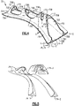
Figure 4 illustrates a perspective view of the platform ofFigure 3 . -
Figure 5 illustrates an isolated view of example fillers from the platform ofFigure 4 . -
Figure 6 illustrates a sectional view of the platform taken along line 6-6 ofFigure 4 . -
Figure 7 illustrates a cross-sectional view of the platform taken along line 6-6 with a bushing. -
Figure 1 schematically illustrates agas turbine engine 20. Thegas turbine engine 20 is disclosed herein as a two-spool turbofan that generally incorporates afan section 22, acompressor section 24, a combustor section 26 and aturbine section 28. Thefan section 22 drives air along a bypass flow path B in a bypass duct defined within ahousing 15, such as a fan case or nacelle, and also drives air along a core flow path C for compression and communication into the combustor section 26 then expansion through theturbine section 28. Although depicted as a two-spool turbofan gas turbine engine in the disclosed non-limiting embodiment, it should be understood that the concepts described herein are not limited to use with two-spool turbofans as the teachings may be applied to other types of turbine engines including three-spool architectures. - The
exemplary engine 20 generally includes alow speed spool 30 and ahigh speed spool 32 mounted for rotation about an engine central longitudinal axis A relative to an enginestatic structure 36 viaseveral bearing systems 38. It should be understood that various bearingsystems 38 at various locations may alternatively or additionally be provided, and the location of bearingsystems 38 may be varied as appropriate to the application. - The
low speed spool 30 generally includes aninner shaft 40 that interconnects, a first (or low)pressure compressor 44 and a first (or low)pressure turbine 46. Theinner shaft 40 is connected to thefan 42 through a speed change mechanism, which in exemplarygas turbine engine 20 is illustrated as a gearedarchitecture 48 to drive afan 42 at a lower speed than thelow speed spool 30. Thehigh speed spool 32 includes anouter shaft 50 that interconnects a second (or high)pressure compressor 52 and a second (or high)pressure turbine 54. Acombustor 56 is arranged inexemplary gas turbine 20 between thehigh pressure compressor 52 and thehigh pressure turbine 54. Amid-turbine frame 57 of the enginestatic structure 36 may be arranged generally between thehigh pressure turbine 54 and thelow pressure turbine 46. Themid-turbine frame 57 furthersupports bearing systems 38 in theturbine section 28. Theinner shaft 40 and theouter shaft 50 are concentric and rotate via bearingsystems 38 about the engine central longitudinal axis A which is collinear with their longitudinal axes. - The core airflow is compressed by the
low pressure compressor 44 then thehigh pressure compressor 52, mixed and burned with fuel in thecombustor 56, then expanded over thehigh pressure turbine 54 andlow pressure turbine 46. Themid-turbine frame 57 includesairfoils 59 which are in the core airflow path C. Theturbines low speed spool 30 andhigh speed spool 32 in response to the expansion. It will be appreciated that each of the positions of thefan section 22,compressor section 24, combustor section 26,turbine section 28, and fandrive gear system 48 may be varied. For example,gear system 48 may be located aft of the low pressure compressor, or aft of the combustor section 26 or even aft ofturbine section 28, andfan 42 may be positioned forward or aft of the location ofgear system 48. - The
engine 20 in one example is a high-bypass geared aircraft engine. In a further example, theengine 20 bypass ratio is greater than about six (6), with an example embodiment being greater than about ten (10), the gearedarchitecture 48 is an epicyclic gear train, such as a planetary gear system or other gear system, with a gear reduction ratio of greater than about 2.3 and thelow pressure turbine 46 has a pressure ratio that is greater than about five. In one disclosed embodiment, theengine 20 bypass ratio is greater than about ten (10:1), the fan diameter is significantly larger than that of thelow pressure compressor 44, and thelow pressure turbine 46 has a pressure ratio that is greater than about five 5:1.Low pressure turbine 46 pressure ratio is pressure measured prior to inlet oflow pressure turbine 46 as related to the pressure at the outlet of thelow pressure turbine 46 prior to an exhaust nozzle. The gearedarchitecture 48 may be an epicycle gear train, such as a planetary gear system or other gear system, with a gear reduction ratio of greater than about 2.3:1 and less than about 5:1. It should be understood, however, that the above parameters are only exemplary of one embodiment of a geared architecture engine and that the present disclosure is applicable to other gas turbine engines including direct drive turbofans. - A significant amount of thrust is provided by the bypass flow B due to the high bypass ratio. The
fan section 22 of theengine 20 is designed for a particular flight condition -- typically cruise at about 0.8 Mach and about 35,000 feet (10,668 meters). The flight condition of 0.8 Mach and 35,000 ft (10,668 meters), with the engine at its best fuel consumption - also known as "bucket cruise Thrust Specific Fuel Consumption ('TSFC')" - is the industry standard parameter of lbm of fuel being burned divided by lbf of thrust the engine produces at that minimum point. "Low fan pressure ratio" is the pressure ratio across the fan blade alone, without a Fan Exit Guide Vane ("FEGV") system. The low fan pressure ratio as disclosed herein according to one non-limiting embodiment is less than about 1.45. "Low corrected fan tip speed" is the actual fan tip speed in ft/sec divided by an industry standard temperature correction of [(Tram °R) / (518.7 °R)]0.5 (where T°R = TK × 9/5). The "Low corrected fan tip speed" as disclosed herein according to one non-limiting embodiment is less than about 1150 ft / second (350.5 meters/second). -
Figure 2 illustrates arotor assembly 60 for thegas turbine engine 20. Therotor assembly 60 can be incorporated as thefan 42 into thefan section 22 ofFigure 1 , for example. However, it should to be understood that other portions of thegas turbine engine 20, such asfan case 15, other portions of the enginestatic structure 36, and airfoils including static vanes in thecompressor section 24, and other systems may benefit from the teachings disclosed herein, such as a multi-stage fan or a land-based turbine. - The
rotor assembly 60 includes arotatable hub 62 mechanically attached or otherwise mounted to afan shaft 64. Therotatable hub 62 includes amain body 62A that extends along the longitudinal axis E. The longitudinal axis E can be parallel to or collinear with the engine longitudinal axis A ofFigure 1 . Thefan shaft 64 andhub 62 are rotatable about the longitudinal axis E. Thefan shaft 64 can be rotatably coupled to thelow pressure turbine 46, as illustrated inFigure 1 , for example. - The
rotor assembly 60 includes an array ofairfoils 66 circumferentially distributed about and carried by anouter periphery 62B of therotatable hub 62. Eachairfoil 66 includes anairfoil section 66A extending from aroot section 66B. Thehub 62 includes a plurality ofretention slots 62C that extend inwardly from theouter periphery 62B of thehub 62. Eachroot section 66B is slideably received in a respective one of theretention slots 62C to mechanically attach or otherwise secure theairfoil 66 to thehub 62. Theroot section 66B can have a dovetail geometry that mates with a contour of therespective retention slot 62C (also shown in dashed lines inFigure 3 for illustrative purposes). - The
rotor assembly 60 includes an array ofplatforms 70. In the illustrative example ofFigure 2 , theplatforms 70 are separate and distinct from theairfoils 66. In other examples, theplatforms 70 are integrally formed with one or more of theairfoils 66. Theplatforms 70 are circumferentially distributed about theouter periphery 62B of thehub 62. Theplatforms 70 are situated between and abut against adjacent pairs ofairfoils 66 to define an inner boundary of a gas path along therotor assembly 60, as illustrated inFigure 2 . Theplatforms 70 are dimensioned to support theadjacent airfoils 66 and limit or otherwise oppose circumferential movement of theairfoils 66 during engine operation. Therotor assembly 60 includes a plurality of retention pins 71. Eachplatform 70 can be mechanically attached or otherwise secured to thehub 62 with a respective one of the retention pins 71. - Referring to
Figure 3 , with continuing reference toFigure 2 , one of theairfoils 66 andplatforms 70 mounted to thehub 62 is shown for illustrative purposes. Theairfoil section 66A extends between a leading edge LE and a trailing edge TE in a chordwise direction X, and extends in a radial direction R between theroot section 66B and atip portion 66C (Figure 2 ) to provide an aerodynamic surface. Thetip portion 66C defines a terminal end or radially outermost extent of theairfoil 66 to establish a clearance gap with fan case 15 (Figure 1 ). Theairfoil section 66A defines a pressure side P (Figure 2 ) and a suction side S separated in a thickness direction T. - Each
platform 70 includes aplatform body 70A including a plurality of axially spaced apartflanges 70B. Theplatform body 70A includes aplatform base 70E dimensioned to abut against and extend along theairfoil section 66A ofadjacent airfoils 66. Theplatform base 70E defines an aerodynamic contour and gas path surface between theadjacent airfoils 66. Theplatform body 70A defines one ormore slots 70C between theflanges 70B. Eachslot 70C is dimensioned to receive arespective flange 62D of thehub 62. Eachflange 62D can have an annular geometry that extends circumferentially about the longitudinal axis E, as illustrated byFigure 2 . - Each
platform 70 is dimensioned to receive at least one retention pin 71 (shown in dashed lines inFigure 3 ) to mechanically attach and mount theplatform 70 to thehub 62. Each of theflanges 70B can include arespective platform bushing 73. Thebushings 73 can be axially aligned and dimensioned to slideably receive a common one of the retention pins 71, as illustrated byFigure 3 . Eachretention pin 71 is dimensioned to extend through theflanges 62D of thehub 62 and through theflanges 70B of therespective platform 70 to mechanically attach theplatform 70 to thehub 62. - The
rotor assembly 60 can include one or more composite components, such as theairfoils 66 and/orplatforms 70. Example composite materials include thermoplastics and ceramics such as ceramic matrix composites (CMC) having one or more ply layers or fibers in a resin matrix. - The
rotor assembly 60 can include one or more internal cavities defined in the composite components. The composite components may be constructed from a layup of plies, for example. Contouring of the component may cause the plies to define the internal cavities. The internal cavities can be at least partially filled or occupied with material utilizing the techniques disclosed herein to improve fabrication and structural support of the component. - Referring to
Figure 4 , with continuing reference toFigure 3 , a perspective view of one of theplatforms 70 is shown. Theplatform 70 is a composite structure including a plurality of composite layers L shaped to a predetermined geometry. The composite layers L define theplatform body 70A andflanges 70B. - Various materials can be utilized to construct the composite layers L. Example materials include one or more plies of uni-tape, braided yarns, fabric, and two-dimensional or three-dimensional woven fibers, for example. It should be appreciated that uni-tape plies include a plurality of fibers oriented in the same direction ("unidirectional), and fabric includes woven or interlaced fibers, each known in the art. Example fiber constructions include carbon fibers, fiberglass, Kevlar®, a ceramic such as Nextel™, a polyethylene such as Spectra®, and/or a combination of fibers.
- The composite layers L include first and second sets of ply layers L-1, L-2 that define an
outer periphery 70P of theplatform 70. The first set of ply layers L-1 define theplatform base 70E. The second set of ply layers L-2 extend from the first set of ply layers L-1 to define theflanges 70B. The composite layers L are arranged such that theflanges 70B form respective arches that extend outwardly from theplatform base 70E to define respectivehollow cavities 70F. - The composite layers L include a third set of ply layers L-3 that abut against the first and second sets of ply layers L-1, L-2 to surround the
hollow cavities 70F. - The
hollow cavities 70F can be arranged to define portions of anelongated passage 70G. Thepassage 70G is at least partially surrounded by the third set of ply layers L-3 and extends longitudinally betweenopposed end portions 70H of theplatform body 70A and through each of theflanges 70B, as illustrated byFigures 4 and6 . Each composite layer L can include one or more sublayers LL, as illustrated byFigures 7 and 8. - The composite layers L can be dimensioned and formed to follow a contour of the
platform 70. At least some of the composite layers L are joined together to define one or more of theinternal cavities 70D. At least some of theinternal cavities 70D are bounded by theplatform base 70E and are defined in theflanges 70B. Eachcavity 70D is at least partially enclosed by adjacent composite layers L and can be provided with one or more openings to an exterior of theplatform 70. - Each
platform 70 can include one or more support members orfillers 74 received in arespective cavity 70D. Thefillers 74 are dimensioned to complement a geometry of a respective one of theinner cavities 70D and serve to at least partially support the adjacent composite layers L during fabrication. Thefillers 74 can also serve as structural members to support the composite layers L during engine operation. - In the illustrated example of
Figure 4 , theplatform 70 includes first and second fillers 74-1, 74-2 that extend along theplatform base 70E. Theplatform 70 includes a plurality offillers 74 that define portions of theflanges 70B, such as filler 74-3. Filler 74-2 is dimensioned to extend along and outwardly from theplatform base 70E to define at least one of theflanges 70B.Figure 5 illustrates a perspective view of the fillers 74-1, 74-2, 74-3 for illustrative purposes. It should be appreciated that the specific geometry of eachfiller 74 can be dimensioned according to a geometry of theplatform 70. - Referring to
Figures 6-7 , with continuing reference toFigure 4 , adjacent layers L can be arranged to define one or more contours of theplatform 70. For example, the layers L can curve inwardly and/or outwardly from adjacent layers L. The geometry of the layers L can cause a cross section or perimeter of the respectiveinternal cavity 70D to taper, as illustrated by theinternal cavities 70D associated with filler 74-1 at junctions J1, J2 and J3. Some of the layers L may arranged to have a relatively large turning radii along the respective contour such that theinternal cavities 70D associated with fillers 74-1, 74-2 have a generally deltoid or delta-shaped geometry formed by inner radii, for example. Thefillers 74 can be utilized to maintain a geometry of theplatform 70 during layup of the layers L, which can improve the structural capability and manufacturability of the layers L. - Various materials can be utilized for the
fillers 74. In the illustrative examples ofFigures 6-7 , the fillers 74-1 and 74-2 include a composite structure 76-1 and 76-2, respectively, situated ininternal cavities 70D adjacent theplatform base 70E. In other examples, the fillers 74-1 and 74-2 are constructed from uni-tape plies, discontinuous chopped fibers in a resin matrix, preforms made of a bulk or sheet molding compound, and/or thermoplastics. - The filler 74-3 includes a stacked composite structure 76-3 situated in one of the
internal cavities 70D spaced furthest from theplatform base 70E and in theflanges 70B. The filler 74-3 is dimensioned to extend between surfaces of the composite layers L that bound the respectiveinternal cavity 70D. The stacked composite structure 76-3 can provide structural support and rigidity to the adjacent layers L and distribute structural loads across portions of theplatform 70. The stacked structure 76-3 includes a multitude of layers formed from discontinuous material sheets that are bonded together by an adhesive or resin material. Because the stacked structure 76-3 is formed from separate layers, a bond line is formed between adjacent layers. - The filler 74-3 also includes an
overwrap ply 76A that surrounds the stacked composite structure 76-3. Theoverwrap ply 76A can be bonded to the stacked composite structure 76-3 with an adhesive or through resin. In the illustrated example, the overwrap ply 76A includes a single layer or ply of composite material that encloses or abuts lateral edges of each layer in the stacked composite structure 76-3 on a first side and one of the layers L on a second opposite side. Because theoverwrap ply 76A is a single layer, it defines a butt joint with a discontinuity that forms an opening into the stacked composite structure 76-3. Alternatively, if the overwrap ply 76A included multiple layers, there would still be a butt joint or opening into the stacked composite structure 76-3 - One feature of the
overwrap ply 76A is reduced crack propagation through the filler 74-3. In particular, if a crack formed between adjacent layers of the stacked composite structure 76-3, theoverwrap ply 76A would prevent the crack from reaching a surface of the filler 74-3 and therefore would improve the strength and longevity of the filler 74-3 as well as theplatform 70. - Furthermore, in the illustrated example of
Figures 4 and6-7 , each of the fillers 74-3 in the flanges 70-B includes abushing 73. The stacked composite structure 76-3 supports thebushing 73 such that the filler 74-3 serves to provide a structural load path between thebushing 73 and composite layers L. - It should be understood that relative positional terms such as "forward," "aft," "upper," "lower," "above," "below," and the like are with reference to the normal operational attitude of the vehicle and should not be considered otherwise limiting.
- Although the different examples have the specific components shown in the illustrations, embodiments of this disclosure are not limited to those particular combinations. It is possible to use some of the components or features from one of the examples in combination with features or components from another one of the examples.
- Although particular step sequences are shown, described, and claimed, it should be understood that steps may be performed in any order, separated or combined unless otherwise indicated and will still benefit from the present disclosure.
- The foregoing description is exemplary rather than defined by the limitations within. Various non-limiting embodiments are disclosed herein, however, one of ordinary skill in the art would recognize that various modifications and variations in light of the above teachings will fall within the scope of the appended claims. It is therefore to be understood that within the scope of the appended claims, the disclosure may be practiced other than as specifically described. For that reason, the appended claims should be studied to determine true scope and content.
Claims (15)
- An assembly (60) for a gas turbine engine (20) comprising:an airfoil (66) including an airfoil section (66A) extending from a root section (66B), the airfoil section (66A) extending between a leading edge (LE) and a trailing edge (TE) in a chordwise direction and extending between a tip portion (66C) and the root section (66B) in a radial direction, and the airfoil section (66A) defining a pressure side (P) and a suction side (S) separated in a thickness direction;a platform (70) dimensioned to receive a retention pin (71) to mount the platform (70) to a rotatable hub (62); andwherein the platform (70) comprises:a plurality of composite layers (L) that define an internal cavity (70D); anda filler (74) including a stacked composite structure (76-1, 76-2, 76-3) in the internal cavity (70D) that extends between the plurality of composite layers (L).
- The assembly (60) of claim 1, wherein the stacked composite structure (76-1, 76-2, 76-3) in the filler (74) includes multitude composite layers arranged in parallel planes.
- The assembly (60) of claim 2, wherein the multitude of composite layers of the stacked composite structure (76-3) are surrounded by an overwrap ply (76A), optionally wherein the overwrap ply (76A) is bonded to lateral edges of the multitude of composite layers of the stacked composite structure (76-3).
- The assembly (60) of claim 3, wherein the overwrap ply (76A) includes a single layer defining a butt joint with a discontinuity in the overwrap ply (76A) to form an opening to the stacked composite structure (76-3).
- The assembly (60) as recited in any preceding claim, wherein the composite layers (L) include bond lines between adjacent sheet segments.
- The assembly (60) as recited in any preceding claim, wherein the plurality of composite layers (L) include first and second sets of ply layers (L-1, L-2) that define an outer periphery of the platform (70), and include a third set of ply layers (L-3) that abut against the first and second sets of ply layers (L-1, L-2) to surround a hollow cavity.
- The assembly (60) as recited in any preceding claim, whereinthe plurality of composite layers (L) are arranged such that a cross section of the internal cavity (70D) has a deltoid shaped geometry;the internal cavity (70D) is defined in the root section (66B);the stacked composite structure (76-3) is machined to accept a bushing (73); anda perimeter of the internal cavity (70D) tapers towards the tip portion (66C).
- A platform (70) for a gas turbine engine (20) comprising:a platform body (70A) defining one or more slots (70C) between a plurality of flanges (70B), the one or more slots (70C) dimensioned to receive a respective flange of a hub (62), and the platform body (70A) including a plurality of composite layers (L) that join together to define an internal cavity (70D); anda filler (74) including a stacked structure (76-1, 76-2, 76-3) having a multitude of composite layers in the internal cavity (70D) and the filler (74) extends between the plurality of composite layers (L).
- The platform (70) of claim 8, whereinthe plurality of composite layers (L) in the stacked composite structure (76-3) are arranged in parallel planes;the multitude of composite layers are surrounded by an overwrap ply (76A);the overwrap ply (76A) is bonded to the multitude of composite layers (L) follows a contour of the internal cavity (70D) on a first side and abuts the stacked composite structure (76-3) on a second opposite side; andthe overwrap ply (76A) includes a single layer defining a butt joint that a discontinuity in the overwrap ply (76A) to form an opening to the stacked composite structure (76-3).
- The platform (70) as recited in claim 8 or 9, wherein the plurality of composite layers (L) include first, second and third sets of ply layers (L-1, L-2, L-3), the first set of ply layers (L-1) defining a platform base (70E) dimensioned to extend between adjacent airfoils (66), the second set of ply layers (L-2) extend from the first set of ply layers (L-1) to define the plurality of flanges (70B), and the third set of ply layers (L-3) abut against the first and second layers to surround a passage (70G) that extends through the plurality of flanges (70B).
- The assembly (60) or platform (70) as recited in any of claims 2 to 10, wherein the multitude of composite layers of the stacked composite structure (76-1, 76-2, 76-3) are formed from discontinuous fiber material sheets.
- The assembly (60) or platform (70) as recited in any preceding claim, wherein the platform (70) includes a bushing (73) in the internal cavity (70D), the bushing (73) is dimensioned to receive a retention pin (71), and the stacked composite structure (76-3) directly engages the bushing (73) to transfer loads to the plurality of composite layers (L) that bound the internal cavity (70D).
- A gas turbine engine (20) comprising:a fan section (22);a compressor section (24);a turbine section (28) that drives the fan section (22) and the compressor section (24); anda rotor assembly (60) comprising:a hub (62) rotatable about an engine longitudinal axis, the hub (62) including a plurality of flanges (70B);an array of airfoils (66) circumferentially distributed about an outer periphery of the hub (62), each one of the airfoils (66) including an airfoil section (66A) extending from a root section (66B) mounted to the hub (62);an array of platforms (70) mechanically attached to the hub (62), each of the platforms (70) including one or more slots (70C) defined by a plurality of flanges (70B), the one or more slots (70C) dimensioned to receive a respective one of the flanges (70B) of the hub (62);a plurality of retention pins (71), each one of the retention pins (71) extending through the flanges (70B) of the hub (62) and through the plurality of flanges (70B) of a respective one of the platforms (70) to mechanically attach the respective one of the platforms (70) to the hub (62); anda plurality of fillers (74) each including a stacked composite structure (76-1, 76-2, 76-3) in a corresponding one of a plurality of internal cavities (70D) in a respective one of the platforms (70), each of the internal cavities (70D) bounded by one or more composite layers (L).
- The gas turbine engine (20) as recited in claim 13, wherein the stacked composite structure (76-1, 76-2, 76-3) includes a multitude of composite layers formed from discontinuous fiber material sheets, optionally wherein the multitude of composite layers of the stacked composite structure (76-3) are surrounded by an overwrap ply (76A), further optionally wherein the overwrap ply (76A) is bonded to lateral edges of the multitude of composite layers (L) of the stacked composite structure (76-3) and the overwrap ply (76A) includes a single layer defining a butt joint with a discontinuity in the overwrap ply (76A) to form an opening to the stacked composite structure (76-3).
- The gas turbine engine (20) as recited in claim 13 or 14, wherein at least one of the airfoil section (66A) and the root section (66B) comprises the one or more composite layers (L) that define a respective one of the internal cavities (70D).
Applications Claiming Priority (1)
| Application Number | Priority Date | Filing Date | Title |
|---|---|---|---|
| US17/187,925 US11725519B2 (en) | 2021-03-01 | 2021-03-01 | Platform for an airfoil of a gas turbine engine |
Publications (2)
| Publication Number | Publication Date |
|---|---|
| EP4053382A1 true EP4053382A1 (en) | 2022-09-07 |
| EP4053382B1 EP4053382B1 (en) | 2025-04-23 |
Family
ID=80623436
Family Applications (1)
| Application Number | Title | Priority Date | Filing Date |
|---|---|---|---|
| EP22159541.6A Active EP4053382B1 (en) | 2021-03-01 | 2022-03-01 | Composite inter-blade platform |
Country Status (2)
| Country | Link |
|---|---|
| US (1) | US11725519B2 (en) |
| EP (1) | EP4053382B1 (en) |
Families Citing this family (1)
| Publication number | Priority date | Publication date | Assignee | Title |
|---|---|---|---|---|
| US20260063045A1 (en) | 2024-08-29 | 2026-03-05 | Rtx Corporation | Reinforced Fan Inter-Blade Platforms |
Citations (6)
| Publication number | Priority date | Publication date | Assignee | Title |
|---|---|---|---|---|
| US20030044570A1 (en) * | 2000-02-25 | 2003-03-06 | George Panagiotis E. | Method of using a laminated composite radius filler |
| EP2727711A1 (en) * | 2012-11-01 | 2014-05-07 | The Boeing Company | Composite radius fillers and methods of forming the same |
| US20150231849A1 (en) * | 2014-02-18 | 2015-08-20 | The Boeing Company | Composite Filler |
| EP3121386A1 (en) * | 2015-07-21 | 2017-01-25 | United Technologies Corporation | Fan blade platform with stiffening feature, corresponding assembly and method |
| US10557361B1 (en) * | 2018-10-16 | 2020-02-11 | United Technologies Corporation | Platform for an airfoil of a gas turbine engine |
| EP3677749A2 (en) * | 2018-12-11 | 2020-07-08 | United Technologies Corporation | Composite gas turbine engine component with lattice structure |
Family Cites Families (5)
| Publication number | Priority date | Publication date | Assignee | Title |
|---|---|---|---|---|
| US5074753A (en) * | 1989-10-16 | 1991-12-24 | Bell Helicopter Textron Inc. | Rotor blade |
| US5240377A (en) * | 1992-02-25 | 1993-08-31 | Williams International Corporation | Composite fan blade |
| US8936440B2 (en) * | 2011-05-26 | 2015-01-20 | United Technologies Corporation | Hybrid rotor disk assembly with ceramic matrix composites platform for a gas turbine engine |
| EP3239469B1 (en) * | 2014-11-20 | 2019-01-09 | Rolls-Royce North American Technologies, Inc. | Composite blades for gas turbine engines |
| US11168572B2 (en) | 2019-02-05 | 2021-11-09 | Raytheon Technologies Corporation | Composite gas turbine engine component |
-
2021
- 2021-03-01 US US17/187,925 patent/US11725519B2/en active Active
-
2022
- 2022-03-01 EP EP22159541.6A patent/EP4053382B1/en active Active
Patent Citations (6)
| Publication number | Priority date | Publication date | Assignee | Title |
|---|---|---|---|---|
| US20030044570A1 (en) * | 2000-02-25 | 2003-03-06 | George Panagiotis E. | Method of using a laminated composite radius filler |
| EP2727711A1 (en) * | 2012-11-01 | 2014-05-07 | The Boeing Company | Composite radius fillers and methods of forming the same |
| US20150231849A1 (en) * | 2014-02-18 | 2015-08-20 | The Boeing Company | Composite Filler |
| EP3121386A1 (en) * | 2015-07-21 | 2017-01-25 | United Technologies Corporation | Fan blade platform with stiffening feature, corresponding assembly and method |
| US10557361B1 (en) * | 2018-10-16 | 2020-02-11 | United Technologies Corporation | Platform for an airfoil of a gas turbine engine |
| EP3677749A2 (en) * | 2018-12-11 | 2020-07-08 | United Technologies Corporation | Composite gas turbine engine component with lattice structure |
Also Published As
| Publication number | Publication date |
|---|---|
| US20220275727A1 (en) | 2022-09-01 |
| EP4053382B1 (en) | 2025-04-23 |
| US11725519B2 (en) | 2023-08-15 |
Similar Documents
| Publication | Publication Date | Title |
|---|---|---|
| EP3613950B1 (en) | Blade outer air seal formed of laminate and having radial support hooks | |
| US11168568B2 (en) | Composite gas turbine engine component with lattice | |
| EP3693548B1 (en) | Gas turbine engine composite platform | |
| EP3736412B1 (en) | Fan inter-blade platform with core and polymer matrix composite skin | |
| EP3816399B1 (en) | Airfoil with encapsulating sheath | |
| US12297751B2 (en) | Turbine engine with composite airfoil having a non-metallic leading edge protective wrap | |
| EP3643885B1 (en) | Platform for an airfoil of a gas turbine engine | |
| EP3816398B1 (en) | Airfoil having sheaths with continuous stiffness joint | |
| EP4053382B1 (en) | Composite inter-blade platform | |
| US11898464B2 (en) | Airfoil for a gas turbine engine | |
| US11391167B2 (en) | Hybrid airfoil for gas turbine engines | |
| EP3808938B1 (en) | Airfoil component with trailing end margin and cutback | |
| EP3708786A2 (en) | Cmc boas with internal support structure | |
| US20240301889A1 (en) | Turbomachine and method of assembly |
Legal Events
| Date | Code | Title | Description |
|---|---|---|---|
| PUAI | Public reference made under article 153(3) epc to a published international application that has entered the european phase |
Free format text: ORIGINAL CODE: 0009012 |
|
| STAA | Information on the status of an ep patent application or granted ep patent |
Free format text: STATUS: THE APPLICATION HAS BEEN PUBLISHED |
|
| AK | Designated contracting states |
Kind code of ref document: A1 Designated state(s): AL AT BE BG CH CY CZ DE DK EE ES FI FR GB GR HR HU IE IS IT LI LT LU LV MC MK MT NL NO PL PT RO RS SE SI SK SM TR |
|
| STAA | Information on the status of an ep patent application or granted ep patent |
Free format text: STATUS: REQUEST FOR EXAMINATION WAS MADE |
|
| 17P | Request for examination filed |
Effective date: 20230307 |
|
| RBV | Designated contracting states (corrected) |
Designated state(s): AL AT BE BG CH CY CZ DE DK EE ES FI FR GB GR HR HU IE IS IT LI LT LU LV MC MK MT NL NO PL PT RO RS SE SI SK SM TR |
|
| RAP3 | Party data changed (applicant data changed or rights of an application transferred) |
Owner name: RTX CORPORATION |
|
| GRAP | Despatch of communication of intention to grant a patent |
Free format text: ORIGINAL CODE: EPIDOSNIGR1 |
|
| STAA | Information on the status of an ep patent application or granted ep patent |
Free format text: STATUS: GRANT OF PATENT IS INTENDED |
|
| INTG | Intention to grant announced |
Effective date: 20240925 |
|
| GRAS | Grant fee paid |
Free format text: ORIGINAL CODE: EPIDOSNIGR3 |
|
| GRAA | (expected) grant |
Free format text: ORIGINAL CODE: 0009210 |
|
| STAA | Information on the status of an ep patent application or granted ep patent |
Free format text: STATUS: THE PATENT HAS BEEN GRANTED |
|
| AK | Designated contracting states |
Kind code of ref document: B1 Designated state(s): AL AT BE BG CH CY CZ DE DK EE ES FI FR GB GR HR HU IE IS IT LI LT LU LV MC MK MT NL NO PL PT RO RS SE SI SK SM TR |
|
| REG | Reference to a national code |
Ref country code: GB Ref legal event code: FG4D |
|
| REG | Reference to a national code |
Ref country code: CH Ref legal event code: EP |
|
| REG | Reference to a national code |
Ref country code: DE Ref legal event code: R096 Ref document number: 602022013379 Country of ref document: DE |
|
| REG | Reference to a national code |
Ref country code: IE Ref legal event code: FG4D |
|
| REG | Reference to a national code |
Ref country code: NL Ref legal event code: MP Effective date: 20250423 |
|
| PG25 | Lapsed in a contracting state [announced via postgrant information from national office to epo] |
Ref country code: NL Free format text: LAPSE BECAUSE OF FAILURE TO SUBMIT A TRANSLATION OF THE DESCRIPTION OR TO PAY THE FEE WITHIN THE PRESCRIBED TIME-LIMIT Effective date: 20250423 |
|
| REG | Reference to a national code |
Ref country code: AT Ref legal event code: MK05 Ref document number: 1787933 Country of ref document: AT Kind code of ref document: T Effective date: 20250423 |
|
| PG25 | Lapsed in a contracting state [announced via postgrant information from national office to epo] |
Ref country code: FI Free format text: LAPSE BECAUSE OF FAILURE TO SUBMIT A TRANSLATION OF THE DESCRIPTION OR TO PAY THE FEE WITHIN THE PRESCRIBED TIME-LIMIT Effective date: 20250423 Ref country code: PT Free format text: LAPSE BECAUSE OF FAILURE TO SUBMIT A TRANSLATION OF THE DESCRIPTION OR TO PAY THE FEE WITHIN THE PRESCRIBED TIME-LIMIT Effective date: 20250825 Ref country code: ES Free format text: LAPSE BECAUSE OF FAILURE TO SUBMIT A TRANSLATION OF THE DESCRIPTION OR TO PAY THE FEE WITHIN THE PRESCRIBED TIME-LIMIT Effective date: 20250423 |
|
| REG | Reference to a national code |
Ref country code: LT Ref legal event code: MG9D |
|
| PG25 | Lapsed in a contracting state [announced via postgrant information from national office to epo] |
Ref country code: GR Free format text: LAPSE BECAUSE OF FAILURE TO SUBMIT A TRANSLATION OF THE DESCRIPTION OR TO PAY THE FEE WITHIN THE PRESCRIBED TIME-LIMIT Effective date: 20250724 Ref country code: NO Free format text: LAPSE BECAUSE OF FAILURE TO SUBMIT A TRANSLATION OF THE DESCRIPTION OR TO PAY THE FEE WITHIN THE PRESCRIBED TIME-LIMIT Effective date: 20250723 |
|
| PG25 | Lapsed in a contracting state [announced via postgrant information from national office to epo] |
Ref country code: PL Free format text: LAPSE BECAUSE OF FAILURE TO SUBMIT A TRANSLATION OF THE DESCRIPTION OR TO PAY THE FEE WITHIN THE PRESCRIBED TIME-LIMIT Effective date: 20250423 |
|
| PG25 | Lapsed in a contracting state [announced via postgrant information from national office to epo] |
Ref country code: BG Free format text: LAPSE BECAUSE OF FAILURE TO SUBMIT A TRANSLATION OF THE DESCRIPTION OR TO PAY THE FEE WITHIN THE PRESCRIBED TIME-LIMIT Effective date: 20250423 |
|
| PG25 | Lapsed in a contracting state [announced via postgrant information from national office to epo] |
Ref country code: HR Free format text: LAPSE BECAUSE OF FAILURE TO SUBMIT A TRANSLATION OF THE DESCRIPTION OR TO PAY THE FEE WITHIN THE PRESCRIBED TIME-LIMIT Effective date: 20250423 |
|
| PG25 | Lapsed in a contracting state [announced via postgrant information from national office to epo] |
Ref country code: AT Free format text: LAPSE BECAUSE OF FAILURE TO SUBMIT A TRANSLATION OF THE DESCRIPTION OR TO PAY THE FEE WITHIN THE PRESCRIBED TIME-LIMIT Effective date: 20250423 |
|
| PG25 | Lapsed in a contracting state [announced via postgrant information from national office to epo] |
Ref country code: RS Free format text: LAPSE BECAUSE OF FAILURE TO SUBMIT A TRANSLATION OF THE DESCRIPTION OR TO PAY THE FEE WITHIN THE PRESCRIBED TIME-LIMIT Effective date: 20250723 |
|
| PG25 | Lapsed in a contracting state [announced via postgrant information from national office to epo] |
Ref country code: IS Free format text: LAPSE BECAUSE OF FAILURE TO SUBMIT A TRANSLATION OF THE DESCRIPTION OR TO PAY THE FEE WITHIN THE PRESCRIBED TIME-LIMIT Effective date: 20250823 |
|
| PG25 | Lapsed in a contracting state [announced via postgrant information from national office to epo] |
Ref country code: LV Free format text: LAPSE BECAUSE OF FAILURE TO SUBMIT A TRANSLATION OF THE DESCRIPTION OR TO PAY THE FEE WITHIN THE PRESCRIBED TIME-LIMIT Effective date: 20250423 |
|
| PG25 | Lapsed in a contracting state [announced via postgrant information from national office to epo] |
Ref country code: DK Free format text: LAPSE BECAUSE OF FAILURE TO SUBMIT A TRANSLATION OF THE DESCRIPTION OR TO PAY THE FEE WITHIN THE PRESCRIBED TIME-LIMIT Effective date: 20250423 Ref country code: SM Free format text: LAPSE BECAUSE OF FAILURE TO SUBMIT A TRANSLATION OF THE DESCRIPTION OR TO PAY THE FEE WITHIN THE PRESCRIBED TIME-LIMIT Effective date: 20250423 |
|
| PG25 | Lapsed in a contracting state [announced via postgrant information from national office to epo] |
Ref country code: CZ Free format text: LAPSE BECAUSE OF FAILURE TO SUBMIT A TRANSLATION OF THE DESCRIPTION OR TO PAY THE FEE WITHIN THE PRESCRIBED TIME-LIMIT Effective date: 20250423 |
|
| PG25 | Lapsed in a contracting state [announced via postgrant information from national office to epo] |
Ref country code: EE Free format text: LAPSE BECAUSE OF FAILURE TO SUBMIT A TRANSLATION OF THE DESCRIPTION OR TO PAY THE FEE WITHIN THE PRESCRIBED TIME-LIMIT Effective date: 20250423 |
|
| REG | Reference to a national code |
Ref country code: DE Ref legal event code: R097 Ref document number: 602022013379 Country of ref document: DE |
|
| PG25 | Lapsed in a contracting state [announced via postgrant information from national office to epo] |
Ref country code: SK Free format text: LAPSE BECAUSE OF FAILURE TO SUBMIT A TRANSLATION OF THE DESCRIPTION OR TO PAY THE FEE WITHIN THE PRESCRIBED TIME-LIMIT Effective date: 20250423 |
|
| PG25 | Lapsed in a contracting state [announced via postgrant information from national office to epo] |
Ref country code: IT Free format text: LAPSE BECAUSE OF FAILURE TO SUBMIT A TRANSLATION OF THE DESCRIPTION OR TO PAY THE FEE WITHIN THE PRESCRIBED TIME-LIMIT Effective date: 20250423 |
|
| PLBE | No opposition filed within time limit |
Free format text: ORIGINAL CODE: 0009261 |
|
| STAA | Information on the status of an ep patent application or granted ep patent |
Free format text: STATUS: NO OPPOSITION FILED WITHIN TIME LIMIT |
|
| REG | Reference to a national code |
Ref country code: CH Ref legal event code: L10 Free format text: ST27 STATUS EVENT CODE: U-0-0-L10-L00 (AS PROVIDED BY THE NATIONAL OFFICE) Effective date: 20260304 |
|
| 26N | No opposition filed |
Effective date: 20260126 |
|
| PGFP | Annual fee paid to national office [announced via postgrant information from national office to epo] |
Ref country code: GB Payment date: 20260219 Year of fee payment: 5 |
|
| PGFP | Annual fee paid to national office [announced via postgrant information from national office to epo] |
Ref country code: DE Payment date: 20260219 Year of fee payment: 5 |
|
| PGFP | Annual fee paid to national office [announced via postgrant information from national office to epo] |
Ref country code: FR Payment date: 20260219 Year of fee payment: 5 |