EP4053014B1 - Assembly and method connecting an aircraft wing aft spar root to an aircraft body fuselage - Google Patents
Assembly and method connecting an aircraft wing aft spar root to an aircraft body fuselage Download PDFInfo
- Publication number
- EP4053014B1 EP4053014B1 EP22151264.3A EP22151264A EP4053014B1 EP 4053014 B1 EP4053014 B1 EP 4053014B1 EP 22151264 A EP22151264 A EP 22151264A EP 4053014 B1 EP4053014 B1 EP 4053014B1
- Authority
- EP
- European Patent Office
- Prior art keywords
- panel
- flange
- aircraft
- rearward extending
- gap
- Prior art date
- Legal status (The legal status is an assumption and is not a legal conclusion. Google has not performed a legal analysis and makes no representation as to the accuracy of the status listed.)
- Active
Links
Images


Classifications
-
- B—PERFORMING OPERATIONS; TRANSPORTING
- B64—AIRCRAFT; AVIATION; COSMONAUTICS
- B64C—AEROPLANES; HELICOPTERS
- B64C1/00—Fuselages; Constructional features common to fuselages, wings, stabilising surfaces or the like
- B64C1/26—Attaching the wing or tail units or stabilising surfaces
-
- B—PERFORMING OPERATIONS; TRANSPORTING
- B64—AIRCRAFT; AVIATION; COSMONAUTICS
- B64F—GROUND OR AIRCRAFT-CARRIER-DECK INSTALLATIONS SPECIALLY ADAPTED FOR USE IN CONNECTION WITH AIRCRAFT; DESIGNING, MANUFACTURING, ASSEMBLING, CLEANING, MAINTAINING OR REPAIRING AIRCRAFT, NOT OTHERWISE PROVIDED FOR; HANDLING, TRANSPORTING, TESTING OR INSPECTING AIRCRAFT COMPONENTS, NOT OTHERWISE PROVIDED FOR
- B64F5/00—Designing, manufacturing, assembling, cleaning, maintaining or repairing aircraft, not otherwise provided for; Handling, transporting, testing or inspecting aircraft components, not otherwise provided for
- B64F5/10—Manufacturing or assembling aircraft, e.g. jigs therefor
-
- B—PERFORMING OPERATIONS; TRANSPORTING
- B64—AIRCRAFT; AVIATION; COSMONAUTICS
- B64C—AEROPLANES; HELICOPTERS
- B64C1/00—Fuselages; Constructional features common to fuselages, wings, stabilising surfaces or the like
- B64C1/06—Frames; Stringers; Longerons ; Fuselage sections
- B64C1/064—Stringers; Longerons
-
- B—PERFORMING OPERATIONS; TRANSPORTING
- B64—AIRCRAFT; AVIATION; COSMONAUTICS
- B64C—AEROPLANES; HELICOPTERS
- B64C3/00—Wings
- B64C3/18—Spars; Ribs; Stringers
- B64C3/185—Spars
Definitions
- This disclosure pertains to an assembly that connects an aircraft wing to an aircraft body. More specifically, this disclosure pertains to an assembly that integrates an aft wing spar root fitting to an aircraft fuselage when joining the aircraft wing to the aircraft body.
- the assembly provides structural strength to the connection between the aircraft wing and the aircraft body, provides corrosion prevention and provides improved inspection capabilities and repair capabilities to the aircraft wing and aircraft body connection.
- the integration or connection of an aircraft wing to an aircraft body for composite material designs of aircraft is challenging in terms of satisfying structural strength requirements, providing corrosion prevention, facilitating the building or assembly of the aircraft wing to the aircraft body and meeting requirements for inspection and repairability of the connection between the aircraft wing and the aircraft body.
- the typical metallic connection architecture between the aft wing spar root fitting and the aircraft body fuselage is difficult to manufacture and often results in peaking loads transferred between a composite spar of the aircraft wing and the composite skin of the aircraft fuselage.
- an assembly connecting an aircraft wing to an aircraft body comprising the aircraft wing, the aircraft body, a panel on the aircraft body, the panel having a panel forward edge, the panel forward edge having a forward edge surface; the panel having a panel bottom, the panel bottom having a panel bottom surface; the panel forward edge surface opposing a rearward edge surface of a rearward extending flange on the aircraft wing; the panel bottom surface opposing a top surface of a rearward extending plate on the aircraft wing; a forward connection connected to the panel and to the rearward extending flange and connecting the panel and the rearward extending flange; the forward connection comprising a forward splice plate, the forward splice plate being engaged in surface engagement with the panel and being connected to the panel; and the forward splice plate being engaged in surface engagement with the rearward extending flange and being connected to the rearward extending flange.
- a method of assembling an aircraft wing to an aircraft body comprising moving the aircraft wing toward the aircraft body; positioning a panel forward edge surface of a panel on the aircraft body opposite a rearward edge surface on a rearward extending flange on the aircraft wing; positioning a panel bottom surface on the panel opposite a top surface on a rearward extending plate on the aircraft wing with there being a gap between the panel bottom surface and the top surface of the rearward extending plate on the aircraft wing; and positioning a plurality of forward splice plates at spatially arranged positions along the panel forward edge surface and along the rearward edge surface of the rearward extending flange; and, connecting the plurality of forward splice plates to the panel and to the rearward extending flange.
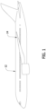
- Figure 1 is a representation of a side elevation view of the port side or left side of an aircraft body 12 with the port side or left side aircraft wing 14 joined to the side of the aircraft body 12.
- the assembly connecting the aircraft wing 14 to the aircraft body 12 to be described refers to the connection of the left side or port side aircraft wing 14 to the aircraft body 12, it should be understood that the concepts of the assembly are equally well applicable to the connection of the starboard side or right side aircraft wing to the aircraft body.
- the assembly and method of this disclosure for connecting the aircraft wing 14 to the aircraft body 12 facilitates the building process of integrating and fitting an aft wing spar root of the aircraft wing 14 to the fuselage of the aircraft body 12.
- the assembly allows improved load paths from the aircraft wing 14 to the aircraft body 12 and thereby reduces the overall weight of the assembly structure.
- Several features of the assembly enable easy inspection at critical joints between the aircraft wing 14 and the aircraft body 12. Improved joints of the assembly allow fay seal application during assembly of the aircraft wing 14 to the aircraft body 12 for corrosion protection at supporting fay seal surfaces.
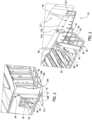
- Figure 2 shows a representation of the root end or inboard end 16 of the aft wing spar 18, or rearward wing spar.
- Figure 3 is a representation of an outboard portion of the fuselage 22 and the outboard end 24 of the aircraft wheel well to which the root end of the aft wing spar 16 represented in Figure 2 is joined.
- the assembly connecting the aircraft wing 14 to the aircraft body 12 includes a trap panel or a panel 26.
- the panel 26 is represented in Figure 3 as connected to the aircraft fuselage 22.
- the outboard side of the panel 26 is represented in Figure 3 .
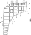
- Figure 4 is a representation of the inboard side of the panel 26 removed from the fuselage 22.
- the panel 26 is often referred to as a "trap" panel due to its general trapezoidal configuration.
- the panel 26 is typically constructed as one, monolithic piece of aluminum to reduce cost. However, other equivalent materials could be employed in constructing the panel 26.
- the panel 26 has a planar, outboard side surface 28 represented in Figure 3 , and an opposite, planar, inboard side surface 32 represented in Figure 4 .
- a thickness dimension of the panel 26 is substantially constant between the outboard side surface 28 and the inboard side surface 32.
- a plurality of outboard stiffener ribs 34 arranged in a grid pattern are formed integrally on the outboard side surface 28 of the panel 26.
- a plurality of inboard stiffener ribs 36 arranged in a grid pattern are formed integrally on the inboard side surface 32 of the panel 26.
- the stiffener ribs 34, 36 add rigidity to the panel 26 and strengthen the panel.
- the panel 26 has a panel forward edge that is directed toward the forward end of the length of the aircraft fuselage.
- the panel forward edge has a forward edge surface 42.
- the forward edge surface 42 has a thickness dimension that is substantially the same as the thickness dimension of the panel 26 between the outboard side surface 28 and the inboard side surface 32 of the panel.
- the panel 26 has a top that is oriented toward the top of the aircraft fuselage of the aircraft body 12.
- a panel top flange 44 is integrally connected to the top of the panel 26.
- the panel top flange 44 projects outwardly from the inboard side surface 32 of the panel 26, but does not project outwardly from the outboard side surface 28 of the panel 26.
- the panel top flange 44 is oriented at a perpendicular orientation or at a right angle relative to the inboard side surface 32 of the panel 26.
- the panel top flange 44 has a panel top surface 46 or a top flange surface 46 that extends along the panel top flange 44.
- the panel top flange surface 46 is generally aligned with the length of the aircraft fuselage.
- the panel 26 has a bottom that is oriented toward the bottom of the aircraft fuselage of the aircraft body 12.
- a panel bottom flange 48 is integrally connected to the bottom of the panel 26.
- the panel bottom flange 48 projects outwardly from the outboard side surface 28 of the panel 26 and from the inboard side surface 32 of the panel 26.
- the panel bottom flange 48 is oriented at an angle relative to the outboard side surface 28 and the inboard side surface 32 of the panel 26.
- the panel bottom flange 48 has a panel bottom surface or bottom flange surface 52 that extends along the panel bottom flange 48.
- the panel bottom flange surface 52 is generally aligned with the length of the aircraft fuselage.
- the panel 26 has a rearward end that is directed toward the rearward end of the length of the aircraft fuselage.
- a panel rearward flange 54 is integrally connected to the rearward end of the panel 26.
- the panel rearward flange 54 extends between the panel top flange 44 and the panel bottom flange 48.
- the panel rearward flange 54 is continuous with the panel top flange 44 and the panel bottom flange 48.
- the panel rearward flange 54 projects outwardly from the outboard side surface 28 of the panel 26 and from the inboard side surface 32 of the panel 26.
- the panel rearward flange 54 is oriented at an angle relative to the outboard side surface 28 of the panel 26 and the inboard side surface 32 of the panel 26.
- the panel rearward flange 54 has a panel rearward surface 56 or a rearward flange surface 56 that extends along the panel rearward flange 54.
- the assembly connecting the aircraft wing 14 to the aircraft body 12 also includes a terminal fitting 62 or a wing rear spar terminal fitting 62.
- the terminal fitting 62 is represented in Figure 2 as attached to the aft wing spar 18 at the inboard, root end of the aircraft wing 14.
- the terminal fitting 62 is represented in Figure 6 as removed from the aft wing spar 18.
- the terminal fitting 62 is constructed of a strong metal, for example titanium. Other equivalent materials could be used to construct the terminal fitting 62. Composite materials could also be used to construct the terminal fitting 62.
- the terminal fitting 62 has a rearward extending flange, or aft flange 64. With the terminal fitting 62 connected to the aircraft wing 14, the aft flange 64 extends in a rearward direction relative to the aircraft body 12.
- the terminal fitting 62 also includes an outboard flange 66.
- the outboard flange 66 extends outwardly or in an outboard direction from the aft flange 64. As represented in Figure 2 , the outboard flange 66 is secured to the inboard end of the aft wing spar 16 by fasteners, or by other equivalent means.
- the terminal fitting 62 also includes an inboard flange 68.
- the inboard flange extends inwardly or in an inboard direction from the aft flange 64.
- the inboard flange 68 is secured to the aircraft fuselage.
- the inboard flange 68 of the terminal fitting 62 is secured by fasteners or by other equivalent means to an aft spar of the center wing box of the aircraft fuselage.
- the aft flange 64 of the terminal fitting 62 has a planar, inboard side surface 72.
- the aft flange 64 of the terminal fitting 62 has a planar, outboard side surface 74.
- a thickness dimension of the aft flange 64 is substantially constant between the outboard side surface 74 and the inboard side surface 72 of the aft flange 64.
- the aft flange 64 has a flange rearward edge that is directed toward the rearward end of the length of the aircraft fuselage.
- the flange rearward edge has a rearward edge surface 76.
- the aft flange rearward edge surface 76 has a thickness dimension that is substantially the same as the thickness dimension of the aft flange 64 between the outboard side surface 74 and the inboard side surface 72 of the aft flange 64.
- the assembly also includes a side fitting 82 or a rear spar side fitting 82.
- the side fitting 82 is represented secured by fasteners or other equivalent means to the aircraft fuselage in Figure 3 and Figure 11 .
- Figure 3 and Figure 11 represent the side fitting 82 secured by fasteners or other equivalent means to an aft spar 84 of the center wing box.
- Figure 7 is a representation of the side fitting 82 removed from the aft spar 84 of the center wing box of the aircraft fuselage.
- the side fitting 82 has a base 86 that is configured or shaped to fit in a vertical orientation flat against the aft spar 84 of the center wing box.
- a vertically oriented inboard flange 88 and a vertically oriented outboard flange 92 extend rearwardly from opposite sides of the side fitting base 86.
- the side fitting 82 has a stiffener flange 94 or a stiffener 94 that extends rearwardly from a top of the base 86.
- the stiffener flange 94 is horizontally oriented relative to the base 86.
- the side fitting stiffener flange 94 or side fitting stiffener 94 aligns with and is positioned in a same plane as a horizontal flange of the aircraft body.
- the side fitting stiffener 94 is aligned with and positioned in a same horizontal plane as a longeron flange 96 of a wheel well longeron 96.
- a splice plate 98 is connected by fasteners to both the stiffener flange 94 of the side fitting 82 and to the wheel well longeron flange 96.
- the splice plate 98 connected between the side fitting 82 and the wheel well longeron flange 96 provides a second, separate load path between the aircraft wing 14 and the fuselage of the aircraft body 12.
- the assembly also includes a main landing gear up-lock fitting 102 or an up-lock fitting 102 on the trap panel 26.
- the up-lock fitting 102 is integrally formed into the reinforcing inboard stiffener ribs 36 that are integral with the inboard side surface 32 of the trap panel 26.
- a bushing (not shown) connects a main landing gear (not shown) to the up-lock fitting 102.
- the up-lock fitting 102 being integrally formed with the trap panel 26 provides a direct load path from the main landing gear into the body of the aircraft and reduces the number of parts required for the connection of the main landing gear to the aircraft body 12, thereby saving weight and improving integration space.
- FIG. 2 , 9 and 10 Also represented in Figures 2 , 9 and 10 is a lower plate 104 or lower splice plate 104 connected to the inboard end of the aircraft wing 14 below the aft flange 64.
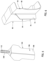
- Figure 5 is a representation of a plan view of the lower splice plate 104 removed from the aircraft wing 14.
- the lower plate 104 is constructed as one, monolithic piece of titanium. However, other equivalent materials could be employed in constructing the lower plate 104.
- Figure 5 is a representation of a plan view of the top of the lower plate 104.
- the lower plate 104 has a configuration with a wide base portion 106 and a more narrow, rearward extending portion 108 or rearward portion 108.
- the base portion 106 of the lower plate 104 is secured to the bottom of the aft wing spar 18 and the bottom of the terminal fitting 62.
- the rearward extending portion 108 of the lower plate 104 projects rearwardly from the connection of the base portion 106 to the aft wing spar 18 and the terminal fitting 62.
- the rearward extending portion 108 of the lower plate 104 has a top surface 112 that extends rearwardly from beneath the aft wing spar 18 and the terminal fitting 62.
- the trap panel 26 Prior to assembling the aircraft wing 14 to the aircraft body 12, the trap panel 26 is connected to the fuselage 22 of the aircraft body 12 as represented in Figures 3 , 9 and 10 .
- the panel 26 is positioned relative to the fuselage 22 with the panel top flange surface 46 engaging against a bottom surface of the fuselage 22.
- An upper connection connects the panel 26 to the bottom surface of the fuselage 22 or to the bottom surface of the aircraft body 12.
- the upper connection is comprised of at least one upper splice plate 114, and preferably a plurality of upper splice plates 114.
- the upper splice plates 114 are generally thin, flat pieces of material such as a composite material or other equivalent type of material.
- the upper splice plates 114 represented in Figures 3 and 9 have general, rectangular configurations. However, the upper splice plates 114 could have other equivalent configurations that enable the upper splice plates 114 to lay flat in surface engagement against the outboard side surface 28 of the panel 26 and the outboard surface of the fuselage 22 as represented in Figures 3 and 9 .
- the upper splice plates 114 are spatially positioned along the panel top surface or the panel top flange 44 and along the outboard surface of the fuselage 22.
- the upper splice plate or plurality of upper splice plates 114 are engaged in surface engagement with the outboard side surface 28 of the panel 26 and are connected to the panel 26 by fasteners such as nut and bolt fasteners or other equivalent types of fasteners, and the upper splice plate or plurality of upper splice plates 114 are engaged in surface engagement with the fuselage 22 of the aircraft body and are connected to the fuselage 22 by fasteners such as nut and bolt fasteners, or other equivalent types of fasteners.
- the upper connection provided by the upper splice plate or upper splice plates 114 connects the panel 26 to the fuselage 22 of the aircraft body 12, or connects the panel 26 to the bottom surface of the fuselage 22 of the aircraft body 12.
- the panel 26 With the upper splice plates 114 secured to the outboard side surface 28 of the panel 26, the panel 26 has exposed surface areas 116 on the panel outboard side surface 28.
- the exposed surface areas 116 are adjacent the panel top flange 44 and between adjacent upper splice plates 114 of the plurality of upper splice plates.
- the panel exposed surfaces 116 provide means for inspection of the outboard side surface 28 of the panel 26 for signs of panel fatigue, for example panel cracks at the panel exposed surface areas 116.
- the assembled aircraft wing 14 is moved toward the aircraft body 12.
- the root end or inboard end of the aft wing spar 16 of the aircraft wing 14 is moved toward the outboard surface of the fuselage 22 and the outboard end of the wheel well 24.
- the movement is continued until the root end 16 or the inboard end of the aft wing spar 16 of the aircraft wing 14 comes into contact with the outboard surface of the fuselage 22.
- the aircraft body 12 and aircraft wing 14 are aligned by moving the wing 14 inboard until an alignment criteria with the fuselage or aircraft body 12 is met (such as the terminal fitting aft flange 64 aligning with the panel forward edge surface 42).
- the movement of the aircraft wing 14 to the aircraft body 12 positions the trap panel forward edge surface 42 opposing the rearward edge surface 76 of the rearward extending aft flange 64 as represented in Figures 9 and 10 .
- the movement of the aircraft wing 14 to the aircraft body 12 also positions the panel bottom flange surface 52 opposing the top surface 112 of the rearward extending portion 108 of the lower splice plate 104.
- FIG. 12 A cross-section view of the gap is represented in Figure 12 .
- the gap has an inboard portion 118 of the gap and an outboard portion 122 of the gap on opposite sides of the gap.
- the inboard portion of the gap 118 tapers as the inboard portion of the gap 118 extends into the gap.
- the outboard portion of the gap 122 also tapers as the outboard portion of the gap 122 extends into the gap.
- a shim is inserted into the gap between the panel bottom flange surface 52 and the top surface 112 of the rearward extending portion 108 of the lower splice plate 104.
- the shim is comprised of an inboard shim 124 and a separate outboard shim 126.
- the inboard shim 124 is inserted into the inboard portion of the gap 118 and the outboard shim 126 is inserted into the outboard portion of the gap 122.
- the tapered cross-section configurations of the inboard portion of the gap 118 and the outboard portion of the gap 122 facilitate the insertions of the inboard shim 124 and the outboard shim 126 into their respective gaps.
- the taper of the shims 124, 126 prevents total scraping off of the fay sealant as the shims are inserted into the gaps.
- the inboard shim 124 and the outboard shim 126 provide fay seals between the aluminum of the trap panel 26 and the titanium of the lower splice plate 104.
- FIG. 9 represents a single, large forward splice plate 128 connecting the panel 26 to the rearward extending flange 64.
- the large forward splice plate 128 is secured to the panel outboard side surface 28 and is secured to the rearward extending flange outboard side surface 74.
- Figure 10 represents a plurality of small forward splice plates 132 connecting the panel 26 to the rearward extending flange 64.
- the plurality of small forward splice plates 132 are secured to the panel inboard side surface 32 and are secured to the reward extending flange inboard side surface 72. It should be understood that a large splice plate 128 could replace the small splice plates 132, and that the small splice plates 132 could replace the large splice plate 128.
- the forward connection splice plates 128, 132 are engaged in surface engagement with the panel 26 and are connected to the panel by fasteners, such as nut and bolt fasteners, and are engaged in surface engagement with the rearward extending aft flange 64 and are connected to the rearward extending flange 64 by fasteners, such as nut and bolt fasteners.
- the plurality of small splice plates 132 are spatially arranged at positions along the forward edge surface 42 of the panel 26 and are spatially arranged at positions along the rearward edge surface 76 of the rearward extending aft flange 64.
- Adjacent small splice plates 132 of the plurality of forward splice plates connected to the panel inboard side surface 32 as represented in Figure 10 leave exposed surface areas 134 on the panel inboard side surface 32 adjacent the panel forward edge surface 42.
- the panel exposed surface areas 134 provide means for inspection of the panel inboard side surface 32 for signs of fatigue, for example the formation of cracks at the panel exposed surface areas 134.
- the assembly and method of this disclosure for connecting the aircraft wing 14 to the aircraft body 12 facilitates the building process of integrating and fitting the inboard end of the aft wing spar 16 of the aircraft wing 14 to the fuselage 22 of the aircraft body 12.
- the assembly provides structural strength to the connection between the aircraft wing 14 and the aircraft body 12.
- the assembly allows an improved load path from the aircraft wing 14 to the aircraft body 12 provided by the splice plates 98, 104, 114, 128, 132, which also reduce the overall weight of the assembly structure.
- the use of the splice plates 98, 104, 114, 128, 132 also enable easy inspection at critical joints between the aircraft wing 14 and the aircraft body 12.
- the improved joints of the assembly allow fay seal application in the gap 118, 122 between the panel bottom flange surface 52 and the lower splice plate top surface 112, providing corrosion protection.
Landscapes
- Engineering & Computer Science (AREA)
- Aviation & Aerospace Engineering (AREA)
- Manufacturing & Machinery (AREA)
- Mechanical Engineering (AREA)
- Transportation (AREA)
- Connection Of Plates (AREA)
Description
- This disclosure pertains to an assembly that connects an aircraft wing to an aircraft body. More specifically, this disclosure pertains to an assembly that integrates an aft wing spar root fitting to an aircraft fuselage when joining the aircraft wing to the aircraft body. The assembly provides structural strength to the connection between the aircraft wing and the aircraft body, provides corrosion prevention and provides improved inspection capabilities and repair capabilities to the aircraft wing and aircraft body connection.
- The integration or connection of an aircraft wing to an aircraft body for composite material designs of aircraft is challenging in terms of satisfying structural strength requirements, providing corrosion prevention, facilitating the building or assembly of the aircraft wing to the aircraft body and meeting requirements for inspection and repairability of the connection between the aircraft wing and the aircraft body. The typical metallic connection architecture between the aft wing spar root fitting and the aircraft body fuselage is difficult to manufacture and often results in peaking loads transferred between a composite spar of the aircraft wing and the composite skin of the aircraft fuselage.
- Document
WO 2008/105805 A2 , according to its abstract, states a trapezoidal panel pin joint for allowing deflection of an aircraft between a fuselage section and a wing section, wherein the pin joint comprises a vertical pin portion, a lug portion, and a clevis portion; wherein at least one vertical flexible tee member is positioned below the pin joint; and wherein the pin joint is coupled to at least two horizontal flexible tee members, such that the pin joint and vertical and horizontal flexible tee members, in combination, release two rotational degrees of freedom. - There is provided an assembly connecting an aircraft wing to an aircraft body, the assembly comprising the aircraft wing, the aircraft body, a panel on the aircraft body, the panel having a panel forward edge, the panel forward edge having a forward edge surface; the panel having a panel bottom, the panel bottom having a panel bottom surface; the panel forward edge surface opposing a rearward edge surface of a rearward extending flange on the aircraft wing; the panel bottom surface opposing a top surface of a rearward extending plate on the aircraft wing; a forward connection connected to the panel and to the rearward extending flange and connecting the panel and the rearward extending flange; the forward connection comprising a forward splice plate, the forward splice plate being engaged in surface engagement with the panel and being connected to the panel; and the forward splice plate being engaged in surface engagement with the rearward extending flange and being connected to the rearward extending flange.
- There is provided a method of assembling an aircraft wing to an aircraft body, the method comprising moving the aircraft wing toward the aircraft body; positioning a panel forward edge surface of a panel on the aircraft body opposite a rearward edge surface on a rearward extending flange on the aircraft wing; positioning a panel bottom surface on the panel opposite a top surface on a rearward extending plate on the aircraft wing with there being a gap between the panel bottom surface and the top surface of the rearward extending plate on the aircraft wing; and positioning a plurality of forward splice plates at spatially arranged positions along the panel forward edge surface and along the rearward edge surface of the rearward extending flange; and, connecting the plurality of forward splice plates to the panel and to the rearward extending flange.
- Further details can be seen with reference to the following description and drawings.
-
-
Figure 1 is a representation of a side elevation view of the left side or port side of an aircraft. -
Figure 2 is a representation of a partial view of a state of assembly of an interior construction of the aft spar and root end of the aircraft wing prior to the wing to body join represented inFigure 1 . -
Figure 3 is a representation of a partial view of a state of assembly of the interior construction of the fuselage in the side of the body of the aircraft prior to the wing to body join represented inFigure 1 . -
Figure 4 is a representation of an elevation view of an inboard side of the trap panel represented inFigure 3 . -
Figure 5 is a representation of a plan view of the rearward extending splice plate represented inFigure 2 . -
Figure 6 is a representation of a perspective view of the wing rear spar terminal fitting removed from the wing as represented inFigure 2 . -
Figure 7 is a representation of a perspective view of the rear spar side fitting removed from the fuselage as represented inFigure 3 . -
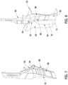
Figure 8 is a representation of a perspective view of the rear spar side fitting and the wing rear spar terminal fitting, which are connected to the aft spar of the center wing box (not shown). -
Figure 9 is a representation of a partial view of an outboard side of a connection between the aft spar of the wing root ofFigure 2 and the fuselage ofFigure 3 . -
Figure 10 is a representation of a partial view of the inboard side of a connection between the aft spar of the wing root ofFigure 2 and the fuselage ofFigure 3 . -
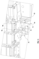
Figure 11 is a representation of a partial view of the inboard side of the connection between the rear spar side fitting ofFigure 7 and a wheel well longeron of the aircraft fuselage. -
Figure 12 is a representation of a cross-section view of the join between the panel bottom flange and the lower splice plate top surface. -
Figure 1 is a representation of a side elevation view of the port side or left side of anaircraft body 12 with the port side or leftside aircraft wing 14 joined to the side of theaircraft body 12. Although the assembly connecting theaircraft wing 14 to theaircraft body 12 to be described refers to the connection of the left side or portside aircraft wing 14 to theaircraft body 12, it should be understood that the concepts of the assembly are equally well applicable to the connection of the starboard side or right side aircraft wing to the aircraft body. The assembly and method of this disclosure for connecting theaircraft wing 14 to theaircraft body 12 facilitates the building process of integrating and fitting an aft wing spar root of theaircraft wing 14 to the fuselage of theaircraft body 12. The assembly allows improved load paths from theaircraft wing 14 to theaircraft body 12 and thereby reduces the overall weight of the assembly structure. Several features of the assembly enable easy inspection at critical joints between theaircraft wing 14 and theaircraft body 12. Improved joints of the assembly allow fay seal application during assembly of theaircraft wing 14 to theaircraft body 12 for corrosion protection at supporting fay seal surfaces. - Referring to
Figures 2 and 3, Figure 2 shows a representation of the root end orinboard end 16 of theaft wing spar 18, or rearward wing spar.Figure 3 is a representation of an outboard portion of thefuselage 22 and theoutboard end 24 of the aircraft wheel well to which the root end of theaft wing spar 16 represented inFigure 2 is joined. As represented inFigure 3 , the assembly connecting theaircraft wing 14 to theaircraft body 12 includes a trap panel or apanel 26. Thepanel 26 is represented inFigure 3 as connected to theaircraft fuselage 22. The outboard side of thepanel 26 is represented inFigure 3 . -
Figure 4 is a representation of the inboard side of thepanel 26 removed from thefuselage 22. Thepanel 26 is often referred to as a "trap" panel due to its general trapezoidal configuration. Thepanel 26 is typically constructed as one, monolithic piece of aluminum to reduce cost. However, other equivalent materials could be employed in constructing thepanel 26. Thepanel 26 has a planar,outboard side surface 28 represented inFigure 3 , and an opposite, planar,inboard side surface 32 represented inFigure 4 . A thickness dimension of thepanel 26 is substantially constant between theoutboard side surface 28 and theinboard side surface 32. A plurality ofoutboard stiffener ribs 34 arranged in a grid pattern are formed integrally on theoutboard side surface 28 of thepanel 26. A plurality ofinboard stiffener ribs 36 arranged in a grid pattern are formed integrally on theinboard side surface 32 of thepanel 26. The stiffener ribs 34, 36 add rigidity to thepanel 26 and strengthen the panel. - The
panel 26 has a panel forward edge that is directed toward the forward end of the length of the aircraft fuselage. The panel forward edge has aforward edge surface 42. Theforward edge surface 42 has a thickness dimension that is substantially the same as the thickness dimension of thepanel 26 between theoutboard side surface 28 and theinboard side surface 32 of the panel. - The
panel 26 has a top that is oriented toward the top of the aircraft fuselage of theaircraft body 12. Apanel top flange 44 is integrally connected to the top of thepanel 26. Thepanel top flange 44 projects outwardly from theinboard side surface 32 of thepanel 26, but does not project outwardly from theoutboard side surface 28 of thepanel 26. Thepanel top flange 44 is oriented at a perpendicular orientation or at a right angle relative to theinboard side surface 32 of thepanel 26. Thepanel top flange 44 has apanel top surface 46 or atop flange surface 46 that extends along thepanel top flange 44. The paneltop flange surface 46 is generally aligned with the length of the aircraft fuselage. - The
panel 26 has a bottom that is oriented toward the bottom of the aircraft fuselage of theaircraft body 12. Apanel bottom flange 48 is integrally connected to the bottom of thepanel 26. The panel bottom flange 48 projects outwardly from theoutboard side surface 28 of thepanel 26 and from theinboard side surface 32 of thepanel 26. Thepanel bottom flange 48 is oriented at an angle relative to theoutboard side surface 28 and theinboard side surface 32 of thepanel 26. Thepanel bottom flange 48 has a panel bottom surface orbottom flange surface 52 that extends along thepanel bottom flange 48. The panelbottom flange surface 52 is generally aligned with the length of the aircraft fuselage. - The
panel 26 has a rearward end that is directed toward the rearward end of the length of the aircraft fuselage. A panel rearwardflange 54 is integrally connected to the rearward end of thepanel 26. The panel rearwardflange 54 extends between thepanel top flange 44 and thepanel bottom flange 48. The panel rearwardflange 54 is continuous with thepanel top flange 44 and thepanel bottom flange 48. The panel rearward flange 54 projects outwardly from theoutboard side surface 28 of thepanel 26 and from theinboard side surface 32 of thepanel 26. The panel rearwardflange 54 is oriented at an angle relative to theoutboard side surface 28 of thepanel 26 and theinboard side surface 32 of thepanel 26. The panel rearwardflange 54 has a panel rearward surface 56 or arearward flange surface 56 that extends along the panel rearwardflange 54. - The assembly connecting the
aircraft wing 14 to theaircraft body 12 also includes a terminal fitting 62 or a wing rear spar terminal fitting 62. Theterminal fitting 62 is represented inFigure 2 as attached to theaft wing spar 18 at the inboard, root end of theaircraft wing 14. Theterminal fitting 62 is represented inFigure 6 as removed from theaft wing spar 18. Theterminal fitting 62 is constructed of a strong metal, for example titanium. Other equivalent materials could be used to construct theterminal fitting 62. Composite materials could also be used to construct theterminal fitting 62. - The
terminal fitting 62 has a rearward extending flange, oraft flange 64. With the terminal fitting 62 connected to theaircraft wing 14, theaft flange 64 extends in a rearward direction relative to theaircraft body 12. Theterminal fitting 62 also includes anoutboard flange 66. Theoutboard flange 66 extends outwardly or in an outboard direction from theaft flange 64. As represented inFigure 2 , theoutboard flange 66 is secured to the inboard end of theaft wing spar 16 by fasteners, or by other equivalent means. Theterminal fitting 62 also includes aninboard flange 68. The inboard flange extends inwardly or in an inboard direction from theaft flange 64. When theaircraft wing 14 is secured to theaircraft body 12, theinboard flange 68 is secured to the aircraft fuselage. In this disclosure, when theaircraft wing 14 is secured to theaircraft body 12, theinboard flange 68 of the terminal fitting 62 is secured by fasteners or by other equivalent means to an aft spar of the center wing box of the aircraft fuselage. As represented inFigures 2 ,6 ,8 and10 , theaft flange 64 of the terminal fitting 62 has a planar,inboard side surface 72. As represented inFigure 9 , theaft flange 64 of the terminal fitting 62 has a planar,outboard side surface 74. A thickness dimension of theaft flange 64 is substantially constant between theoutboard side surface 74 and theinboard side surface 72 of theaft flange 64. - The
aft flange 64 has a flange rearward edge that is directed toward the rearward end of the length of the aircraft fuselage. The flange rearward edge has arearward edge surface 76. The aft flange rearwardedge surface 76 has a thickness dimension that is substantially the same as the thickness dimension of theaft flange 64 between theoutboard side surface 74 and theinboard side surface 72 of theaft flange 64. - The assembly also includes a side fitting 82 or a rear spar side fitting 82. The side fitting 82 is represented secured by fasteners or other equivalent means to the aircraft fuselage in
Figure 3 andFigure 11 .Figure 3 andFigure 11 represent the side fitting 82 secured by fasteners or other equivalent means to anaft spar 84 of the center wing box.Figure 7 is a representation of the side fitting 82 removed from theaft spar 84 of the center wing box of the aircraft fuselage. As represented inFigure 7 , the side fitting 82 has a base 86 that is configured or shaped to fit in a vertical orientation flat against theaft spar 84 of the center wing box. A vertically orientedinboard flange 88 and a vertically orientedoutboard flange 92 extend rearwardly from opposite sides of the sidefitting base 86. The side fitting 82 has astiffener flange 94 or astiffener 94 that extends rearwardly from a top of thebase 86. Thestiffener flange 94 is horizontally oriented relative to thebase 86. As represented inFigures 3 ,9 and 10 , the sidefitting stiffener flange 94 or sidefitting stiffener 94 aligns with and is positioned in a same plane as a horizontal flange of the aircraft body. As represented inFigure 10 , the sidefitting stiffener 94 is aligned with and positioned in a same horizontal plane as alongeron flange 96 of awheel well longeron 96. - As represented in
Figure 11 , asplice plate 98 is connected by fasteners to both thestiffener flange 94 of the side fitting 82 and to the wheelwell longeron flange 96. Thesplice plate 98 connected between the side fitting 82 and the wheelwell longeron flange 96 provides a second, separate load path between theaircraft wing 14 and the fuselage of theaircraft body 12. - The assembly also includes a main landing gear up-
lock fitting 102 or an up-lock fitting 102 on thetrap panel 26. As represented inFigures 4 and10 , the up-lock fitting 102 is integrally formed into the reinforcinginboard stiffener ribs 36 that are integral with theinboard side surface 32 of thetrap panel 26. A bushing (not shown) connects a main landing gear (not shown) to the up-lock fitting 102. The up-lock fitting 102 being integrally formed with thetrap panel 26 provides a direct load path from the main landing gear into the body of the aircraft and reduces the number of parts required for the connection of the main landing gear to theaircraft body 12, thereby saving weight and improving integration space. - Also represented in
Figures 2 ,9 and 10 is alower plate 104 orlower splice plate 104 connected to the inboard end of theaircraft wing 14 below theaft flange 64.Figure 5 is a representation of a plan view of thelower splice plate 104 removed from theaircraft wing 14. Thelower plate 104 is constructed as one, monolithic piece of titanium. However, other equivalent materials could be employed in constructing thelower plate 104.Figure 5 is a representation of a plan view of the top of thelower plate 104. As represented inFigures 2 ,5 ,9 and 10 , thelower plate 104 has a configuration with awide base portion 106 and a more narrow, rearward extendingportion 108 orrearward portion 108. Thebase portion 106 of thelower plate 104 is secured to the bottom of theaft wing spar 18 and the bottom of theterminal fitting 62. The rearward extendingportion 108 of thelower plate 104 projects rearwardly from the connection of thebase portion 106 to theaft wing spar 18 and theterminal fitting 62. The rearward extendingportion 108 of thelower plate 104 has atop surface 112 that extends rearwardly from beneath theaft wing spar 18 and theterminal fitting 62. - Prior to assembling the
aircraft wing 14 to theaircraft body 12, thetrap panel 26 is connected to thefuselage 22 of theaircraft body 12 as represented inFigures 3 ,9 and 10 . Thepanel 26 is positioned relative to thefuselage 22 with the paneltop flange surface 46 engaging against a bottom surface of thefuselage 22. An upper connection connects thepanel 26 to the bottom surface of thefuselage 22 or to the bottom surface of theaircraft body 12. The upper connection is comprised of at least oneupper splice plate 114, and preferably a plurality ofupper splice plates 114. As represented inFigures 3 and9 , theupper splice plates 114 are generally thin, flat pieces of material such as a composite material or other equivalent type of material. Theupper splice plates 114 represented inFigures 3 and9 have general, rectangular configurations. However, theupper splice plates 114 could have other equivalent configurations that enable theupper splice plates 114 to lay flat in surface engagement against theoutboard side surface 28 of thepanel 26 and the outboard surface of thefuselage 22 as represented inFigures 3 and9 . Theupper splice plates 114 are spatially positioned along the panel top surface or the paneltop flange 44 and along the outboard surface of thefuselage 22. The upper splice plate or plurality ofupper splice plates 114 are engaged in surface engagement with theoutboard side surface 28 of thepanel 26 and are connected to thepanel 26 by fasteners such as nut and bolt fasteners or other equivalent types of fasteners, and the upper splice plate or plurality ofupper splice plates 114 are engaged in surface engagement with thefuselage 22 of the aircraft body and are connected to thefuselage 22 by fasteners such as nut and bolt fasteners, or other equivalent types of fasteners. The upper connection provided by the upper splice plate orupper splice plates 114 connects thepanel 26 to thefuselage 22 of theaircraft body 12, or connects thepanel 26 to the bottom surface of thefuselage 22 of theaircraft body 12. - With the
upper splice plates 114 secured to theoutboard side surface 28 of thepanel 26, thepanel 26 has exposedsurface areas 116 on the panel outboardside surface 28. The exposedsurface areas 116 are adjacent the paneltop flange 44 and between adjacentupper splice plates 114 of the plurality of upper splice plates. The panel exposedsurfaces 116 provide means for inspection of theoutboard side surface 28 of thepanel 26 for signs of panel fatigue, for example panel cracks at the panel exposedsurface areas 116. - In assembling the
aircraft wing 14 to theaircraft body 12, the assembledaircraft wing 14 is moved toward theaircraft body 12. The root end or inboard end of theaft wing spar 16 of theaircraft wing 14 is moved toward the outboard surface of thefuselage 22 and the outboard end of thewheel well 24. The movement is continued until theroot end 16 or the inboard end of theaft wing spar 16 of theaircraft wing 14 comes into contact with the outboard surface of thefuselage 22. Alternatively, theaircraft body 12 andaircraft wing 14 are aligned by moving thewing 14 inboard until an alignment criteria with the fuselage oraircraft body 12 is met (such as the terminal fitting aftflange 64 aligning with the panel forward edge surface 42). - The movement of the
aircraft wing 14 to theaircraft body 12 positions the trap panel forward edgesurface 42 opposing therearward edge surface 76 of the rearward extendingaft flange 64 as represented inFigures 9 and 10 . The movement of theaircraft wing 14 to theaircraft body 12 also positions the panelbottom flange surface 52 opposing thetop surface 112 of the rearward extendingportion 108 of thelower splice plate 104. - There is a gap between the panel
bottom flange surface 52 and thetop surface 112 of the rearward extendingportion 108 of thelower splice plate 104. A cross-section view of the gap is represented inFigure 12 . The gap has aninboard portion 118 of the gap and anoutboard portion 122 of the gap on opposite sides of the gap. As represented inFigure 12 , the inboard portion of thegap 118 tapers as the inboard portion of thegap 118 extends into the gap. The outboard portion of thegap 122 also tapers as the outboard portion of thegap 122 extends into the gap. - With the movement of the
aircraft wing 14 to theaircraft body 12 positioning the panelbottom flange surface 52 opposite thetop surface 112 of the rearward extendingportion 108 of thelower splice plate 104 as represented inFigures 9, 10 , and12 , a shim is inserted into the gap between the panelbottom flange surface 52 and thetop surface 112 of the rearward extendingportion 108 of thelower splice plate 104. The shim is comprised of aninboard shim 124 and a separateoutboard shim 126. Theinboard shim 124 is inserted into the inboard portion of thegap 118 and theoutboard shim 126 is inserted into the outboard portion of thegap 122. The tapered cross-section configurations of the inboard portion of thegap 118 and the outboard portion of thegap 122 facilitate the insertions of theinboard shim 124 and theoutboard shim 126 into their respective gaps. After installation, there is a gap between theinboard shim 124 and theoutboard shim 126 that allows a squeeze out of the fay sealant. The taper of theshims inboard shim 124 and theoutboard shim 126 provide fay seals between the aluminum of thetrap panel 26 and the titanium of thelower splice plate 104. - There is a forward connection connected to the
panel 26 and connected to the rearward extendingaft flange 64 on theaircraft wing 14. The forward connection is represented inFigures 9, 10 and11 . The forward connection connects thepanel 26 to the rearward extendingaft flange 64. The forward connection is comprised of a forward splice plate, or a plurality of forward splice plates.Figure 9 represents a single, largeforward splice plate 128 connecting thepanel 26 to the rearward extendingflange 64. The largeforward splice plate 128 is secured to the panel outboardside surface 28 and is secured to the rearward extending flange outboardside surface 74.Figure 10 represents a plurality of smallforward splice plates 132 connecting thepanel 26 to the rearward extendingflange 64. The plurality of smallforward splice plates 132 are secured to the panel inboardside surface 32 and are secured to the reward extending flange inboardside surface 72. It should be understood that alarge splice plate 128 could replace thesmall splice plates 132, and that thesmall splice plates 132 could replace thelarge splice plate 128. InFigures 9 and 10 , the forwardconnection splice plates panel 26 and are connected to the panel by fasteners, such as nut and bolt fasteners, and are engaged in surface engagement with the rearward extendingaft flange 64 and are connected to the rearward extendingflange 64 by fasteners, such as nut and bolt fasteners. InFigure 10 , the plurality ofsmall splice plates 132 are spatially arranged at positions along theforward edge surface 42 of thepanel 26 and are spatially arranged at positions along therearward edge surface 76 of the rearward extendingaft flange 64. - Adjacent
small splice plates 132 of the plurality of forward splice plates connected to the panel inboardside surface 32 as represented inFigure 10 leave exposedsurface areas 134 on the panel inboardside surface 32 adjacent the panel forward edgesurface 42. The panel exposedsurface areas 134 provide means for inspection of the panel inboardside surface 32 for signs of fatigue, for example the formation of cracks at the panel exposedsurface areas 134. - The assembly and method of this disclosure for connecting the
aircraft wing 14 to theaircraft body 12 facilitates the building process of integrating and fitting the inboard end of theaft wing spar 16 of theaircraft wing 14 to thefuselage 22 of theaircraft body 12. The assembly provides structural strength to the connection between theaircraft wing 14 and theaircraft body 12. The assembly allows an improved load path from theaircraft wing 14 to theaircraft body 12 provided by thesplice plates splice plates aircraft wing 14 and theaircraft body 12. The improved joints of the assembly allow fay seal application in thegap bottom flange surface 52 and the lower splice platetop surface 112, providing corrosion protection. - As various modifications could be made in the construction of the assembly and method for connecting an aircraft wing to an aircraft body herein described and illustrated without departing from the scope of the invention, it is intended that all matter contained in the foregoing description or shown in the accompanying drawings shall be interpreted as illustrative rather than limiting. Thus, the breadth and scope of the present disclosure should not be limited by any of the above described exemplary embodiments, but should be defined only in accordance with the following claims appended hereto.
Claims (15)
- An assembly connecting an aircraft wing (14) to an aircraft body (12), the assembly comprising:the aircraft wing (14); a rearward extending flange (64) on the aircraft wing, the rearward extending flange having a rearward edge surface; a rearward extending plate (104, 108) on the aircraft wing, the rearward extending plate having a top surface;the aircraft body (12);a panel (26) on the aircraft body (12), the panel having a panel forward edge, the panel forward edge having a forward edge surface (42);the panel having a panel bottom, the panel bottom having a panel bottom surface (52);the panel forward edge surface (42) opposing the rearward edge surface of the rearward extending flange (64) on the aircraft wing (14);the panel bottom surface (52) opposing the top surface of the rearward extending plate on the aircraft wing (14);a forward connection connected to the panel and to the rearward extending flange (64) and connecting the panel (26) and the rearward extending flange (64);the forward connection comprising a forward splice plate (128, 132), the forward splice plate (128, 132) being engaged in surface engagement with the panel (26) and being connected to the panel (26); and,the forward splice plate (128, 132) being engaged in surface engagement with the rearward extending flange and being connected to the rearward extending flange.
- The assembly of claim 1, further comprising:
the forward splice plate being one of a plurality of forward splice plates, the plurality of forward splice plates being spatially positioned along the panel (26) forward edge surface and along the rearward edge surface of the rearward extending flange. - The assembly of claim 2, further comprising:the panel (26) having a panel (26) exposed surface area on the panel (26) adjacent the panel (26) forward edge, the panel (26) exposed surface area being between adjacent forward splice plates of the plurality of forward splice plates spatially positioned along the panel (26) forward edge surface;the rearward extending flange having a flange exposed surface area on the rearward extending flange adjacent the rearward edge surface of the rearward extending flange, the flange exposed surface area being between adjacent forward splice plates of the plurality of forward splice plates spatially positioned along the rearward edge surface of the rearward extending flange;the panel (26) exposed surface area providing means for inspection of the panel (26) exposed surface area; and,the flange exposed surface area providing means for inspection of the flange exposed surface area.
- The assembly of any of claims 1 to 3, further comprising:a gap between the panel (26) bottom surface and the top surface of the rearward extending plate on the aircraft wing (14); and,a shim inserted into the gap between the panel (26) bottom surface and the top surface of the rearward extending plate on the aircraft wing (14).
- The assembly of claim 4, further comprising:the gap having an inboard portion of the gap and the gap having an outboard portion of the gap on opposite sides of the gap;the inboard portion of the gap tapering as the inboard portion of the gap extends into the gap; and,the outboard portion of the gap tapering as the outboard portion of the gap extends into the gap;in particular whereinthe shim comprises an inboard shim and a separate outboard shim;the inboard shim being inserted into the inboard portion of the gap; and,the outboard shim being inserted into the outboard portion of the gap.
- The assembly of any of claims 1 to 5, further comprising:a fitting (62), the fitting (62) being connected to the rearward extending flange on the aircraft wing (14);the fitting (62) having a base, the base being vertically oriented;the fitting (62) having a stiffener flange, the stiffener flange extending rearwardly from a top of the base, the stiffener flange being horizontally oriented; and,an upper connection, the upper connection being connected to the stiffener and the upper connection being connected to the aircraft body (12).
- The assembly of claim 6, further comprising:
the upper connection comprising an upper splice plate, the upper splice plate being connected to the stiffener and the upper splice plate being connected to the aircraft body (12). - The assembly of claim 7, further comprising the upper splice plate being connected to the stiffener and the upper splice plate being connected to a wheel well longeron of the aircraft body (12).
- The assembly of any of claims 1 to 8, further comprising:
an up-lock fitting (102) on the panel (26), the up-lock fitting (102) being integrally formed on the panel (26), the up-lock fitting (102) having means for connection of the up-lock fitting (102) to a landing gear. - The assembly of claim 9, further comprising:the panel (26) having stiffener ribs integrally formed on the panel (26); and,the up-lock fitting (102) being integrally formed into the stiffener ribs integrally formed on the panel (26).
- A method of assembling an aircraft wing (14) to an aircraft body (12), the method comprising:moving the aircraft wing (14) toward the aircraft body (12);positioning a panel forward edge surface (42) of a panel (26) on the aircraft body (12) opposite a rearward edge surface on a rearward extending flange (64) on the aircraft wing (14);positioning a panel bottom surface (52) on the panel opposite a top surface on a rearward extending plate on the aircraft wing (14) with there being a gap between the panel bottom surface and the top surface of the rearward extending plate on the aircraft wing (14); andpositioning a plurality of forward splice plates at spatially arranged positions along the panel forward edge surface and along the rearward edge surface of the rearward extending flange; and,connecting the plurality of forward splice plates to the panel and to the rearward extending flange.
- The method of claim 11, further comprising:
leaving exposed surface areas on the panel along the panel forward edge surface between adjacent forward splice plates of the plurality of forward splice plates with the exposed surface areas providing means for inspecting the panel along the panel forward edge surface. - The method of any of claims 10 to 12, further comprising:positioning a plurality of upper splice plates at spatially arranged positions along a top of the panel and along a fuselage frame of the aircraft body; and,connecting the plurality of upper splice plates to the panel and to the fuselage frame.
- The method of any of claims 10 to 13, further comprising:
inserting shims (124, 126) into the gap between the panel bottom surface and the top surface of the rearward extending plate on the aircraft wing. - The method of any of claims 10 to 14, further comprising:inserting an inboard shim (124) into an inboard portion of the gap between the panel bottom surface and the top surface of the rearward extending plate on the aircraft wing; and,inserting an outboard shim (126) into an outboard portion of the gap between the panel bottom surface and the top surface of the rearward extending plate on the aircraft wing.
Applications Claiming Priority (1)
| Application Number | Priority Date | Filing Date | Title |
|---|---|---|---|
| US202163157327P | 2021-03-05 | 2021-03-05 |
Publications (2)
| Publication Number | Publication Date |
|---|---|
| EP4053014A1 EP4053014A1 (en) | 2022-09-07 |
| EP4053014B1 true EP4053014B1 (en) | 2024-12-18 |
Family
ID=79601892
Family Applications (1)
| Application Number | Title | Priority Date | Filing Date |
|---|---|---|---|
| EP22151264.3A Active EP4053014B1 (en) | 2021-03-05 | 2022-01-13 | Assembly and method connecting an aircraft wing aft spar root to an aircraft body fuselage |
Country Status (4)
| Country | Link |
|---|---|
| US (1) | US11952101B2 (en) |
| EP (1) | EP4053014B1 (en) |
| BR (1) | BR102022000759A2 (en) |
| CA (1) | CA3145714C (en) |
Family Cites Families (6)
| Publication number | Priority date | Publication date | Assignee | Title |
|---|---|---|---|---|
| US5518208A (en) * | 1993-12-28 | 1996-05-21 | The Boeing Company | Optimum aircraft body frame to body skin shear tie installation pattern for body skin/stringer circumferential splices |
| GB0511417D0 (en) * | 2005-06-03 | 2005-07-13 | Airbus Uk Ltd | Landing gear |
| GB0525896D0 (en) * | 2005-12-20 | 2006-02-01 | Airbus Uk Ltd | A joint for use in aircraft construction |
| US7546979B1 (en) * | 2006-09-15 | 2009-06-16 | The Boeing Company | Trapezoidal panel pin joint allowing free deflection between fuselage and wing |
| US8016236B2 (en) * | 2007-04-04 | 2011-09-13 | The Boeing Company | Method and apparatus for attaching a wing to a body |
| US11136107B2 (en) * | 2018-10-05 | 2021-10-05 | The Boeing Company | Method and apparatus for attaching a fuselage frame to a wing box |
-
2022
- 2022-01-13 EP EP22151264.3A patent/EP4053014B1/en active Active
- 2022-01-13 CA CA3145714A patent/CA3145714C/en active Active
- 2022-01-14 BR BR102022000759-4A patent/BR102022000759A2/en unknown
- 2022-03-03 US US17/685,961 patent/US11952101B2/en active Active
Also Published As
| Publication number | Publication date |
|---|---|
| CA3145714C (en) | 2026-01-20 |
| CA3145714A1 (en) | 2022-09-05 |
| EP4053014A1 (en) | 2022-09-07 |
| BR102022000759A2 (en) | 2022-09-13 |
| US11952101B2 (en) | 2024-04-09 |
| US20220281582A1 (en) | 2022-09-08 |
Similar Documents
| Publication | Publication Date | Title |
|---|---|---|
| US9580164B2 (en) | Apparatus and methods for joining aircraft composite structures | |
| US7887009B2 (en) | Methods and systems for attaching aircraft wings to fuselages | |
| US8371532B2 (en) | Aircraft joint | |
| US9004406B2 (en) | Aircraft wing box joint | |
| US8398024B2 (en) | Wing cover panel assembly and wing cover panel for an aircraft wing and a method of forming thereof | |
| CN101883717B (en) | System of aircraft fuselage two sections and connection structure for fuselage skin connection | |
| US8715808B2 (en) | Method for coupling stiffening profile elements and structural component | |
| CN101410292B (en) | Aircraft component, aircraft structure and method for manufacturing the component and structure | |
| US20100243810A1 (en) | Integrative structure for aircraft fairing | |
| JP5808112B2 (en) | Composite structure and aircraft main wing provided with the same | |
| US20150217852A1 (en) | Aircraft structure | |
| EP4053014A1 (en) | Assembly and method connecting an aircraft wing aft spar root to an aircraft body fuselage | |
| CN214648983U (en) | Connection structure of wing and body of light airplane | |
| US20080105786A1 (en) | Stringer for an aircraft wing and a method of reinforcing thereof | |
| CN114802698A (en) | Joint for connecting a center wing box and a compartment in an aircraft | |
| CN111003139B (en) | Airtight floors for civil aircraft | |
| EP4596393A1 (en) | Fitting structure for aircraft fuselage | |
| US12522365B2 (en) | Assembly for an aircraft comprising a wing and a reactor mast for coupling a propulsion system to said wing | |
| US20200122816A1 (en) | Bulkhead joint assembly | |
| EP4610165A1 (en) | Wing-fuselage truss joint | |
| CN121626397A (en) | Assembly structure for aircraft fuselage | |
| FR3096660A1 (en) | PRIMARY STRUCTURE OF A MAST FOR A REACTOR OF AN AIRCRAFT |
Legal Events
| Date | Code | Title | Description |
|---|---|---|---|
| PUAI | Public reference made under article 153(3) epc to a published international application that has entered the european phase |
Free format text: ORIGINAL CODE: 0009012 |
|
| STAA | Information on the status of an ep patent application or granted ep patent |
Free format text: STATUS: THE APPLICATION HAS BEEN PUBLISHED |
|
| AK | Designated contracting states |
Kind code of ref document: A1 Designated state(s): AL AT BE BG CH CY CZ DE DK EE ES FI FR GB GR HR HU IE IS IT LI LT LU LV MC MK MT NL NO PL PT RO RS SE SI SK SM TR |
|
| STAA | Information on the status of an ep patent application or granted ep patent |
Free format text: STATUS: REQUEST FOR EXAMINATION WAS MADE |
|
| 17P | Request for examination filed |
Effective date: 20230112 |
|
| RBV | Designated contracting states (corrected) |
Designated state(s): AL AT BE BG CH CY CZ DE DK EE ES FI FR GB GR HR HU IE IS IT LI LT LU LV MC MK MT NL NO PL PT RO RS SE SI SK SM TR |
|
| RAP3 | Party data changed (applicant data changed or rights of an application transferred) |
Owner name: THE BOEING COMPANY |
|
| GRAP | Despatch of communication of intention to grant a patent |
Free format text: ORIGINAL CODE: EPIDOSNIGR1 |
|
| STAA | Information on the status of an ep patent application or granted ep patent |
Free format text: STATUS: GRANT OF PATENT IS INTENDED |
|
| INTG | Intention to grant announced |
Effective date: 20240712 |
|
| P01 | Opt-out of the competence of the unified patent court (upc) registered |
Free format text: CASE NUMBER: APP_42701/2024 Effective date: 20240719 |
|
| GRAS | Grant fee paid |
Free format text: ORIGINAL CODE: EPIDOSNIGR3 |
|
| GRAA | (expected) grant |
Free format text: ORIGINAL CODE: 0009210 |
|
| STAA | Information on the status of an ep patent application or granted ep patent |
Free format text: STATUS: THE PATENT HAS BEEN GRANTED |
|
| AK | Designated contracting states |
Kind code of ref document: B1 Designated state(s): AL AT BE BG CH CY CZ DE DK EE ES FI FR GB GR HR HU IE IS IT LI LT LU LV MC MK MT NL NO PL PT RO RS SE SI SK SM TR |
|
| REG | Reference to a national code |
Ref country code: CH Ref legal event code: EP |
|
| REG | Reference to a national code |
Ref country code: DE Ref legal event code: R096 Ref document number: 602022008694 Country of ref document: DE |
|
| REG | Reference to a national code |
Ref country code: IE Ref legal event code: FG4D |
|
| REG | Reference to a national code |
Ref country code: LT Ref legal event code: MG9D |
|
| PG25 | Lapsed in a contracting state [announced via postgrant information from national office to epo] |
Ref country code: HR Free format text: LAPSE BECAUSE OF FAILURE TO SUBMIT A TRANSLATION OF THE DESCRIPTION OR TO PAY THE FEE WITHIN THE PRESCRIBED TIME-LIMIT Effective date: 20241218 |
|
| PG25 | Lapsed in a contracting state [announced via postgrant information from national office to epo] |
Ref country code: FI Free format text: LAPSE BECAUSE OF FAILURE TO SUBMIT A TRANSLATION OF THE DESCRIPTION OR TO PAY THE FEE WITHIN THE PRESCRIBED TIME-LIMIT Effective date: 20241218 |
|
| PG25 | Lapsed in a contracting state [announced via postgrant information from national office to epo] |
Ref country code: BG Free format text: LAPSE BECAUSE OF FAILURE TO SUBMIT A TRANSLATION OF THE DESCRIPTION OR TO PAY THE FEE WITHIN THE PRESCRIBED TIME-LIMIT Effective date: 20241218 |
|
| PG25 | Lapsed in a contracting state [announced via postgrant information from national office to epo] |
Ref country code: NO Free format text: LAPSE BECAUSE OF FAILURE TO SUBMIT A TRANSLATION OF THE DESCRIPTION OR TO PAY THE FEE WITHIN THE PRESCRIBED TIME-LIMIT Effective date: 20250318 |
|
| REG | Reference to a national code |
Ref country code: NL Ref legal event code: MP Effective date: 20241218 |
|
| PG25 | Lapsed in a contracting state [announced via postgrant information from national office to epo] |
Ref country code: LV Free format text: LAPSE BECAUSE OF FAILURE TO SUBMIT A TRANSLATION OF THE DESCRIPTION OR TO PAY THE FEE WITHIN THE PRESCRIBED TIME-LIMIT Effective date: 20241218 Ref country code: GR Free format text: LAPSE BECAUSE OF FAILURE TO SUBMIT A TRANSLATION OF THE DESCRIPTION OR TO PAY THE FEE WITHIN THE PRESCRIBED TIME-LIMIT Effective date: 20250319 |
|
| PG25 | Lapsed in a contracting state [announced via postgrant information from national office to epo] |
Ref country code: RS Free format text: LAPSE BECAUSE OF FAILURE TO SUBMIT A TRANSLATION OF THE DESCRIPTION OR TO PAY THE FEE WITHIN THE PRESCRIBED TIME-LIMIT Effective date: 20250318 |
|
| PG25 | Lapsed in a contracting state [announced via postgrant information from national office to epo] |
Ref country code: NL Free format text: LAPSE BECAUSE OF FAILURE TO SUBMIT A TRANSLATION OF THE DESCRIPTION OR TO PAY THE FEE WITHIN THE PRESCRIBED TIME-LIMIT Effective date: 20241218 |
|
| REG | Reference to a national code |
Ref country code: AT Ref legal event code: MK05 Ref document number: 1752058 Country of ref document: AT Kind code of ref document: T Effective date: 20241218 |
|
| PG25 | Lapsed in a contracting state [announced via postgrant information from national office to epo] |
Ref country code: SM Free format text: LAPSE BECAUSE OF FAILURE TO SUBMIT A TRANSLATION OF THE DESCRIPTION OR TO PAY THE FEE WITHIN THE PRESCRIBED TIME-LIMIT Effective date: 20241218 |
|
| PG25 | Lapsed in a contracting state [announced via postgrant information from national office to epo] |
Ref country code: PL Free format text: LAPSE BECAUSE OF FAILURE TO SUBMIT A TRANSLATION OF THE DESCRIPTION OR TO PAY THE FEE WITHIN THE PRESCRIBED TIME-LIMIT Effective date: 20241218 |
|
| PG25 | Lapsed in a contracting state [announced via postgrant information from national office to epo] |
Ref country code: ES Free format text: LAPSE BECAUSE OF FAILURE TO SUBMIT A TRANSLATION OF THE DESCRIPTION OR TO PAY THE FEE WITHIN THE PRESCRIBED TIME-LIMIT Effective date: 20241218 |
|
| PG25 | Lapsed in a contracting state [announced via postgrant information from national office to epo] |
Ref country code: IS Free format text: LAPSE BECAUSE OF FAILURE TO SUBMIT A TRANSLATION OF THE DESCRIPTION OR TO PAY THE FEE WITHIN THE PRESCRIBED TIME-LIMIT Effective date: 20250418 |
|
| PG25 | Lapsed in a contracting state [announced via postgrant information from national office to epo] |
Ref country code: PT Free format text: LAPSE BECAUSE OF FAILURE TO SUBMIT A TRANSLATION OF THE DESCRIPTION OR TO PAY THE FEE WITHIN THE PRESCRIBED TIME-LIMIT Effective date: 20250421 |
|
| PG25 | Lapsed in a contracting state [announced via postgrant information from national office to epo] |
Ref country code: EE Free format text: LAPSE BECAUSE OF FAILURE TO SUBMIT A TRANSLATION OF THE DESCRIPTION OR TO PAY THE FEE WITHIN THE PRESCRIBED TIME-LIMIT Effective date: 20241218 |
|
| PG25 | Lapsed in a contracting state [announced via postgrant information from national office to epo] |
Ref country code: AT Free format text: LAPSE BECAUSE OF FAILURE TO SUBMIT A TRANSLATION OF THE DESCRIPTION OR TO PAY THE FEE WITHIN THE PRESCRIBED TIME-LIMIT Effective date: 20241218 Ref country code: RO Free format text: LAPSE BECAUSE OF FAILURE TO SUBMIT A TRANSLATION OF THE DESCRIPTION OR TO PAY THE FEE WITHIN THE PRESCRIBED TIME-LIMIT Effective date: 20241218 |
|
| PG25 | Lapsed in a contracting state [announced via postgrant information from national office to epo] |
Ref country code: SK Free format text: LAPSE BECAUSE OF FAILURE TO SUBMIT A TRANSLATION OF THE DESCRIPTION OR TO PAY THE FEE WITHIN THE PRESCRIBED TIME-LIMIT Effective date: 20241218 |
|
| PG25 | Lapsed in a contracting state [announced via postgrant information from national office to epo] |
Ref country code: CZ Free format text: LAPSE BECAUSE OF FAILURE TO SUBMIT A TRANSLATION OF THE DESCRIPTION OR TO PAY THE FEE WITHIN THE PRESCRIBED TIME-LIMIT Effective date: 20241218 |
|
| PG25 | Lapsed in a contracting state [announced via postgrant information from national office to epo] |
Ref country code: IT Free format text: LAPSE BECAUSE OF FAILURE TO SUBMIT A TRANSLATION OF THE DESCRIPTION OR TO PAY THE FEE WITHIN THE PRESCRIBED TIME-LIMIT Effective date: 20241218 |
|
| REG | Reference to a national code |
Ref country code: CH Ref legal event code: PL |
|
| PG25 | Lapsed in a contracting state [announced via postgrant information from national office to epo] |
Ref country code: SE Free format text: LAPSE BECAUSE OF FAILURE TO SUBMIT A TRANSLATION OF THE DESCRIPTION OR TO PAY THE FEE WITHIN THE PRESCRIBED TIME-LIMIT Effective date: 20241218 |
|
| PG25 | Lapsed in a contracting state [announced via postgrant information from national office to epo] |
Ref country code: MC Free format text: LAPSE BECAUSE OF FAILURE TO SUBMIT A TRANSLATION OF THE DESCRIPTION OR TO PAY THE FEE WITHIN THE PRESCRIBED TIME-LIMIT Effective date: 20241218 Ref country code: LU Free format text: LAPSE BECAUSE OF NON-PAYMENT OF DUE FEES Effective date: 20250113 |
|
| REG | Reference to a national code |
Ref country code: DE Ref legal event code: R097 Ref document number: 602022008694 Country of ref document: DE |
|
| PG25 | Lapsed in a contracting state [announced via postgrant information from national office to epo] |
Ref country code: DK Free format text: LAPSE BECAUSE OF FAILURE TO SUBMIT A TRANSLATION OF THE DESCRIPTION OR TO PAY THE FEE WITHIN THE PRESCRIBED TIME-LIMIT Effective date: 20241218 |
|
| PG25 | Lapsed in a contracting state [announced via postgrant information from national office to epo] |
Ref country code: BE Free format text: LAPSE BECAUSE OF NON-PAYMENT OF DUE FEES Effective date: 20250131 |
|
| PG25 | Lapsed in a contracting state [announced via postgrant information from national office to epo] |
Ref country code: CH Free format text: LAPSE BECAUSE OF NON-PAYMENT OF DUE FEES Effective date: 20250131 |
|
| REG | Reference to a national code |
Ref country code: BE Ref legal event code: MM Effective date: 20250131 |
|
| PLBE | No opposition filed within time limit |
Free format text: ORIGINAL CODE: 0009261 |
|
| STAA | Information on the status of an ep patent application or granted ep patent |
Free format text: STATUS: NO OPPOSITION FILED WITHIN TIME LIMIT |
|
| 26N | No opposition filed |
Effective date: 20250919 |
|
| PG25 | Lapsed in a contracting state [announced via postgrant information from national office to epo] |
Ref country code: IE Free format text: LAPSE BECAUSE OF NON-PAYMENT OF DUE FEES Effective date: 20250113 |
|
| PGFP | Annual fee paid to national office [announced via postgrant information from national office to epo] |
Ref country code: GB Payment date: 20260127 Year of fee payment: 5 |
|
| PGFP | Annual fee paid to national office [announced via postgrant information from national office to epo] |
Ref country code: DE Payment date: 20260128 Year of fee payment: 5 |
|
| PGFP | Annual fee paid to national office [announced via postgrant information from national office to epo] |
Ref country code: FR Payment date: 20260126 Year of fee payment: 5 |