EP4052917A1 - Liquid discharge apparatus, printer, and liquid discharge method - Google Patents
Liquid discharge apparatus, printer, and liquid discharge method Download PDFInfo
- Publication number
- EP4052917A1 EP4052917A1 EP22158292.7A EP22158292A EP4052917A1 EP 4052917 A1 EP4052917 A1 EP 4052917A1 EP 22158292 A EP22158292 A EP 22158292A EP 4052917 A1 EP4052917 A1 EP 4052917A1
- Authority
- EP
- European Patent Office
- Prior art keywords
- liquid
- discharge
- sheet
- ultraviolet
- pigment
- Prior art date
- Legal status (The legal status is an assumption and is not a legal conclusion. Google has not performed a legal analysis and makes no representation as to the accuracy of the status listed.)
- Granted
Links
Images


Classifications
-
- B—PERFORMING OPERATIONS; TRANSPORTING
- B41—PRINTING; LINING MACHINES; TYPEWRITERS; STAMPS
- B41J—TYPEWRITERS; SELECTIVE PRINTING MECHANISMS, i.e. MECHANISMS PRINTING OTHERWISE THAN FROM A FORME; CORRECTION OF TYPOGRAPHICAL ERRORS
- B41J11/00—Devices or arrangements of selective printing mechanisms, e.g. ink-jet printers or thermal printers, for supporting or handling copy material in sheet or web form
- B41J11/0015—Devices or arrangements of selective printing mechanisms, e.g. ink-jet printers or thermal printers, for supporting or handling copy material in sheet or web form for treating before, during or after printing or for uniform coating or laminating the copy material before or after printing
- B41J11/002—Curing or drying the ink on the copy materials, e.g. by heating or irradiating
- B41J11/0021—Curing or drying the ink on the copy materials, e.g. by heating or irradiating using irradiation
- B41J11/00214—Curing or drying the ink on the copy materials, e.g. by heating or irradiating using irradiation using UV radiation
-
- B—PERFORMING OPERATIONS; TRANSPORTING
- B41—PRINTING; LINING MACHINES; TYPEWRITERS; STAMPS
- B41J—TYPEWRITERS; SELECTIVE PRINTING MECHANISMS, i.e. MECHANISMS PRINTING OTHERWISE THAN FROM A FORME; CORRECTION OF TYPOGRAPHICAL ERRORS
- B41J11/00—Devices or arrangements of selective printing mechanisms, e.g. ink-jet printers or thermal printers, for supporting or handling copy material in sheet or web form
- B41J11/0005—Curl smoothing, i.e. smoothing down corrugated printing material, e.g. by pressing means acting on wrinkled printing material
-
- B—PERFORMING OPERATIONS; TRANSPORTING
- B41—PRINTING; LINING MACHINES; TYPEWRITERS; STAMPS
- B41J—TYPEWRITERS; SELECTIVE PRINTING MECHANISMS, i.e. MECHANISMS PRINTING OTHERWISE THAN FROM A FORME; CORRECTION OF TYPOGRAPHICAL ERRORS
- B41J11/00—Devices or arrangements of selective printing mechanisms, e.g. ink-jet printers or thermal printers, for supporting or handling copy material in sheet or web form
- B41J11/0015—Devices or arrangements of selective printing mechanisms, e.g. ink-jet printers or thermal printers, for supporting or handling copy material in sheet or web form for treating before, during or after printing or for uniform coating or laminating the copy material before or after printing
- B41J11/002—Curing or drying the ink on the copy materials, e.g. by heating or irradiating
- B41J11/0021—Curing or drying the ink on the copy materials, e.g. by heating or irradiating using irradiation
- B41J11/00216—Curing or drying the ink on the copy materials, e.g. by heating or irradiating using irradiation using infrared [IR] radiation or microwaves
-
- B—PERFORMING OPERATIONS; TRANSPORTING
- B41—PRINTING; LINING MACHINES; TYPEWRITERS; STAMPS
- B41J—TYPEWRITERS; SELECTIVE PRINTING MECHANISMS, i.e. MECHANISMS PRINTING OTHERWISE THAN FROM A FORME; CORRECTION OF TYPOGRAPHICAL ERRORS
- B41J11/00—Devices or arrangements of selective printing mechanisms, e.g. ink-jet printers or thermal printers, for supporting or handling copy material in sheet or web form
- B41J11/0015—Devices or arrangements of selective printing mechanisms, e.g. ink-jet printers or thermal printers, for supporting or handling copy material in sheet or web form for treating before, during or after printing or for uniform coating or laminating the copy material before or after printing
- B41J11/002—Curing or drying the ink on the copy materials, e.g. by heating or irradiating
- B41J11/0021—Curing or drying the ink on the copy materials, e.g. by heating or irradiating using irradiation
- B41J11/00218—Constructional details of the irradiation means, e.g. radiation source attached to reciprocating print head assembly or shutter means provided on the radiation source
-
- B—PERFORMING OPERATIONS; TRANSPORTING
- B41—PRINTING; LINING MACHINES; TYPEWRITERS; STAMPS
- B41J—TYPEWRITERS; SELECTIVE PRINTING MECHANISMS, i.e. MECHANISMS PRINTING OTHERWISE THAN FROM A FORME; CORRECTION OF TYPOGRAPHICAL ERRORS
- B41J11/00—Devices or arrangements of selective printing mechanisms, e.g. ink-jet printers or thermal printers, for supporting or handling copy material in sheet or web form
- B41J11/007—Conveyor belts or like feeding devices
-
- B—PERFORMING OPERATIONS; TRANSPORTING
- B41—PRINTING; LINING MACHINES; TYPEWRITERS; STAMPS
- B41J—TYPEWRITERS; SELECTIVE PRINTING MECHANISMS, i.e. MECHANISMS PRINTING OTHERWISE THAN FROM A FORME; CORRECTION OF TYPOGRAPHICAL ERRORS
- B41J11/00—Devices or arrangements of selective printing mechanisms, e.g. ink-jet printers or thermal printers, for supporting or handling copy material in sheet or web form
- B41J11/0085—Using suction for maintaining printing material flat
-
- B—PERFORMING OPERATIONS; TRANSPORTING
- B41—PRINTING; LINING MACHINES; TYPEWRITERS; STAMPS
- B41J—TYPEWRITERS; SELECTIVE PRINTING MECHANISMS, i.e. MECHANISMS PRINTING OTHERWISE THAN FROM A FORME; CORRECTION OF TYPOGRAPHICAL ERRORS
- B41J2/00—Typewriters or selective printing mechanisms characterised by the printing or marking process for which they are designed
- B41J2/005—Typewriters or selective printing mechanisms characterised by the printing or marking process for which they are designed characterised by bringing liquid or particles selectively into contact with a printing material
- B41J2/01—Ink jet
- B41J2/21—Ink jet for multi-colour printing
- B41J2/2107—Ink jet for multi-colour printing characterised by the ink properties
- B41J2/2114—Ejecting specialized liquids, e.g. transparent or processing liquids
- B41J2/2117—Ejecting white liquids
-
- B—PERFORMING OPERATIONS; TRANSPORTING
- B41—PRINTING; LINING MACHINES; TYPEWRITERS; STAMPS
- B41J—TYPEWRITERS; SELECTIVE PRINTING MECHANISMS, i.e. MECHANISMS PRINTING OTHERWISE THAN FROM A FORME; CORRECTION OF TYPOGRAPHICAL ERRORS
- B41J2/00—Typewriters or selective printing mechanisms characterised by the printing or marking process for which they are designed
- B41J2/525—Arrangement for multi-colour printing, not covered by group B41J2/21, e.g. applicable to two or more kinds of printing or marking process
-
- C—CHEMISTRY; METALLURGY
- C09—DYES; PAINTS; POLISHES; NATURAL RESINS; ADHESIVES; COMPOSITIONS NOT OTHERWISE PROVIDED FOR; APPLICATIONS OF MATERIALS NOT OTHERWISE PROVIDED FOR
- C09D—COATING COMPOSITIONS, e.g. PAINTS, VARNISHES OR LACQUERS; FILLING PASTES; CHEMICAL PAINT OR INK REMOVERS; INKS; CORRECTING FLUIDS; WOODSTAINS; PASTES OR SOLIDS FOR COLOURING OR PRINTING; USE OF MATERIALS THEREFOR
- C09D11/00—Inks
- C09D11/02—Printing inks
- C09D11/10—Printing inks based on artificial resins
- C09D11/101—Inks specially adapted for printing processes involving curing by wave energy or particle radiation, e.g. with UV-curing following the printing
-
- C—CHEMISTRY; METALLURGY
- C09—DYES; PAINTS; POLISHES; NATURAL RESINS; ADHESIVES; COMPOSITIONS NOT OTHERWISE PROVIDED FOR; APPLICATIONS OF MATERIALS NOT OTHERWISE PROVIDED FOR
- C09D—COATING COMPOSITIONS, e.g. PAINTS, VARNISHES OR LACQUERS; FILLING PASTES; CHEMICAL PAINT OR INK REMOVERS; INKS; CORRECTING FLUIDS; WOODSTAINS; PASTES OR SOLIDS FOR COLOURING OR PRINTING; USE OF MATERIALS THEREFOR
- C09D11/00—Inks
- C09D11/30—Inkjet printing inks
- C09D11/32—Inkjet printing inks characterised by colouring agents
- C09D11/322—Pigment inks
-
- C—CHEMISTRY; METALLURGY
- C09—DYES; PAINTS; POLISHES; NATURAL RESINS; ADHESIVES; COMPOSITIONS NOT OTHERWISE PROVIDED FOR; APPLICATIONS OF MATERIALS NOT OTHERWISE PROVIDED FOR
- C09D—COATING COMPOSITIONS, e.g. PAINTS, VARNISHES OR LACQUERS; FILLING PASTES; CHEMICAL PAINT OR INK REMOVERS; INKS; CORRECTING FLUIDS; WOODSTAINS; PASTES OR SOLIDS FOR COLOURING OR PRINTING; USE OF MATERIALS THEREFOR
- C09D11/00—Inks
- C09D11/30—Inkjet printing inks
- C09D11/40—Ink-sets specially adapted for multi-colour inkjet printing
-
- B—PERFORMING OPERATIONS; TRANSPORTING
- B41—PRINTING; LINING MACHINES; TYPEWRITERS; STAMPS
- B41J—TYPEWRITERS; SELECTIVE PRINTING MECHANISMS, i.e. MECHANISMS PRINTING OTHERWISE THAN FROM A FORME; CORRECTION OF TYPOGRAPHICAL ERRORS
- B41J25/00—Actions or mechanisms not otherwise provided for
- B41J2025/008—Actions or mechanisms not otherwise provided for comprising a plurality of print heads placed around a drum
-
- B—PERFORMING OPERATIONS; TRANSPORTING
- B41—PRINTING; LINING MACHINES; TYPEWRITERS; STAMPS
- B41J—TYPEWRITERS; SELECTIVE PRINTING MECHANISMS, i.e. MECHANISMS PRINTING OTHERWISE THAN FROM A FORME; CORRECTION OF TYPOGRAPHICAL ERRORS
- B41J2202/00—Embodiments of or processes related to ink-jet or thermal heads
- B41J2202/01—Embodiments of or processes related to ink-jet heads
- B41J2202/21—Line printing
Definitions
- aspects of this disclosure relates to a liquid discharge apparatus, a printer, and a liquid discharge method.
- a printer applies a liquid onto a printing object such as a sheet to perform a printing operation.
- the printer include a printer using a liquid curable by active energy rays such as ultraviolet rays, a printer heats and dries a liquid applied onto a sheet by ultraviolet irradiation, and the like.
- the printer may use a water-based ink curable by an active energy ray (see Japanese Unexamined Patent Application Publication No. 2013-180436 ).
- An active energy curable ink such as an ultraviolet curable ink has a problem in that an environmental load is larger than that of a water-based pigment ink.
- An object of the present disclosure is to provide a liquid discharge apparatus capable of efficiently dry a sheet while reducing an environmental load.
- a liquid discharge apparatus includes a first liquid that generates heat in an absorption wavelength region of an active energy ray, a first discharger configured to discharge the first liquid, a second liquid that starts polymerization in the absorption wavelength region of the active energy ray, a second discharger configured to discharge the second liquid, and an irradiator configured to irradiate the first liquid and the second liquid with the active energy ray.
- a printer in another aspect of this disclosure, includes a first liquid that generates heat in an absorption wavelength region of an active energy ray, a first discharger configured to discharge the first liquid, a second liquid that starts polymerization in the absorption wavelength region of the active energy ray, a second discharger configured to discharge the second liquid, and an irradiator configured to irradiate the first liquid and the second liquid with the active energy ray.
- a liquid discharging method includes discharging a first liquid that generates heat in an absorption wavelength region of an active energy ray, discharging a second liquid that starts polymerization in the absorption wavelength region of the active energy ray, and irradiating the first liquid and the second liquid with the active energy ray.
- the liquid discharge apparatus according to the present disclosure can efficiently dry a sheet while reducing an environmental load.
- FIGS. 1 and 2 A printer as a liquid discharge apparatus according to a first embodiment of the present disclosure is described with reference to FIGS. 1 and 2 .
- FIG. 1 is a schematic side view of the printer 1 according to the first embodiment.
- FIG. 2 is a schematic plan view of a discharge unit 33 of the printer 1.
- the printer 1 includes a loading unit 10 to load a sheet P into the printer 1, a pretreatment unit 20, a printing unit 30, a first dryer 40 and a second dryer 50, a reverse mechanism 60, and an ejection unit 70.
- the pretreatment unit 20 serves as a coater to apply (coat) a pretreatment liquid onto the sheet P.
- the pretreatment unit 20 applies, as desired, a pretreatment liquid as an application liquid onto the sheet P fed (supplied) from the loading unit 10, the printing unit 30 applies a desired liquid onto the sheet P to perform desired printing.
- the printer 1 After the printer 1 dries the liquid adhering to the sheet P by the first dryer 40 and the second dryer 50, the printer 1 ejects the sheet P to the ejection unit 70 through the reverse mechanism 60 without printing on a back surface of the sheet P.
- the printer 1 may print on both sides of the sheet P via the reversing mechanism 60 after the printer 1 dries the liquid adhering to the sheet P by the first dryer 40 and the second dryer 50, and the printer 1 then ejects the sheet P to the ejection unit 70.
- the loading unit 10 includes loading trays 11 (a lower loading tray 11A and an upper loading tray 11B) to accommodate multiple sheets P and feeding devices 12 (a feeding device 12A and a feeding device 12B) to separate and feed the multiple sheets P one by one from the loading trays 11, and supplies the sheet P to the pretreatment unit 20.
- loading trays 11 a lower loading tray 11A and an upper loading tray 11B
- feeding devices 12 a feeding device 12A and a feeding device 12B
- the pretreatment unit 20 includes, e.g., a coater 21 as a treatment-liquid application unit that coats a printing surface of the sheet P with a treatment liquid having an effect of aggregation of ink particles to prevent bleed-through.
- a coater 21 as a treatment-liquid application unit that coats a printing surface of the sheet P with a treatment liquid having an effect of aggregation of ink particles to prevent bleed-through.
- the printing unit 30 includes a drum 31 and a liquid discharge device 32.
- the drum 31 is a bearer (rotator) that bears the sheet P on a circumferential surface of the drum 31 and rotates.
- the liquid discharge device 32 discharges liquids toward the sheet P borne on the drum 31.
- the printing unit 30 includes transfer cylinders 34 and 35.
- the transfer cylinder 34 receives the sheet P fed from the pretreatment unit 20 and forwards the sheet P to the drum 31.
- the transfer cylinder 35 receives the sheet P conveyed by the drum 31 and forwards the sheet P to the first dryer 40.
- the transfer cylinder 34 includes a sheet gripper to grip a leading end of the sheet P conveyed from the pretreatment unit 20 to the printing unit 30.
- the sheet P thus gripped by the transfer cylinder 34 is conveyed as the transfer cylinder 34 rotates.
- the transfer cylinder 34 forwards the sheet P to the drum 31 at a position opposite (facing) the drum 31.
- the drum 31 includes a sheet gripper on a surface of the drum 31, and the leading end of the sheet P is gripped by the sheet gripper of the drum 31.
- the drum 31 includes multiple suction holes dispersed on a surface of the drum 31.
- a suction device generates suction airflows directed from desired suction holes of the drum 31 to an interior of the drum 31.
- the sheet gripper of the drum 31 grips the leading end of the sheet P forwarded from the transfer cylinder 34 to the drum 31, and the sheet P is attracted to and borne on the drum 31 by the suction airflows generated by the suction device. As the drum 31 rotates, the sheet P is conveyed.
- the liquid discharge device 32 includes discharge units 33 (discharge units 33A to 33E) to discharge liquids onto the sheet P as a liquid application unit.
- discharge units 33A discharges a liquid of cyan (C)
- the discharge unit 33B discharges a liquid of magenta (M)
- the discharge unit 33C discharges a liquid of yellow (Y)
- the discharge unit 33D discharges a liquid of black (K)
- the discharge unit 33E discharges a liquid of white (W).
- the discharge unit 33 may discharge a special liquid, that is, a liquid of spot color such as gold, silver, and the like.
- the first liquid includes multiple types of colors of inks
- the first discharger (discharge unit 33) includes multiple first dischargers (discharge units 33A to 33D) configured to respectively discharge multiple types of colors of inks such as liquids of cyan (C), magenta (M), yellow (Y), and black (K).
- each of the discharge unit 33 includes a head module 100 including a full-line head.
- the head module 100 includes multiple liquid discharge heads 101 arranged in a staggered manner on a base 103.
- Each of the liquid discharge head 101 includes multiple nozzle arrays, and multiple nozzles 111 are arranged in each of the nozzle arrays.
- the "liquid discharge head 101" is simply referred to as a "head 101".
- a discharge operation of each of the discharge unit 33 of the liquid discharge device 32 is controlled by a drive signal corresponding to print data.
- the liquids of respective colors are discharged from the discharge units 33 toward the sheet P, and an image corresponding to the print data is formed on the sheet P.
- the first dryer 40 includes a heating device 42 such as an infrared (IR) heater.
- the heating device 42 of the first dryer 40 irradiates the sheet P, onto which the liquid has been applied, with infrared rays to heat and dry the sheet P conveyed by the conveyor 41.
- the second dryer 50 includes a heating device 52 such as an ultraviolet (UV) ray irradiator to irradiate the liquid on the sheet P with ultraviolet rays as active energy rays, for example.
- the heating device 52 of the second dryer 50 irradiates the sheet P, to which the liquid has been applied, with infrared rays to heat and dry the sheet P passed through the first dryer 40 and conveyed by a conveyor 51.
- the conveyor 41 and the conveyor 51 may include a part of same conveyance mechanism.
- the reverse mechanism 60 includes a reverse path 61 and a duplex path 62.
- the reverse path 61 reverses the sheet P that has passed through the first dryer 40 and the second dryer 50 to dry one surface of the sheet P onto which the liquid is applied when the printer 1 performs a duplex printing.
- the duplex path 62 feeds the reversed sheet P back to upstream (right side in FIG. 1 ) of the transfer cylinder 34 of the printing unit 30.
- the reverse path 61 reverses the sheet P by switchback manner.
- the ejection unit 70 includes an ejection tray 71 on which the multiple sheets P are stacked.
- the multiple sheets P conveyed from the reverse mechanism 60 are sequentially stacked and held on the ejection tray 71.
- embodiments of the present disclosure can also be applied to an apparatus using a continuous medium (web) such as continuous paper or roll paper, an apparatus using a sheet material such as wallpaper, and the like.
- a continuous medium such as continuous paper or roll paper
- a sheet material such as wallpaper, and the like.
- the discharge units 33A to 33D are first dischargers that discharge the first liquid 801 (see FIG. 3 ) that generates heat in an absorption wavelength region of ultraviolet ray as an active energy ray.
- the first liquid 801 is a water-based pigment ink. That is, the water-based pigment ink is used as ink of each color of C, M, Y, and K (non-white ink).
- Atypical composition of the water-based pigment ink is about 90% by mass of water and other high boiling point solvents, about 5% by mass of resin, and about 5% by mass of pigment colorant.
- the composition of the water-based pigment ink is not limited to the composition as described above and may be any other compositions.
- a colorant of the pigment carbon black may be used for black (K)
- copper phthalocyanine may be used for cyan (C)
- quinacridone may be used for magenta (M)
- monoazo yellow may be used for yellow (Y), for example.
- the printer 1 can obtain (print) a vivid printed image that does not fade even when the printed image is irradiated with ultraviolet rays unlike an ink using a colorant of dye.
- the discharge unit 33E is a second discharger that discharges the second liquid 802 (see FIG. 3 ) that starts polymerization in an absorption wave range of ultraviolet rays as active energy rays.
- the second liquid 802 is an ultraviolet curable ink.
- ultraviolet curable ink is used as a white ink (W-ink).
- the ultraviolet curable ink contains an ultraviolet polymerization initiator and an ultraviolet polymerization monomer.
- the polymerization initiator becomes an active state of a radical or a cation.
- the activated polymerization initiator reacts with the monomer so that the monomer is polymerized and cured as a resin.
- the ultraviolet curable ink is used for the white ink to reduce cockling in a white portion of the printed image.
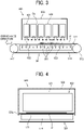
- heating device 52 is described with reference to FIGS. 3 and 4 .
- FIG. 3 is a schematic cross-sectional side view of the heating device 500 according to the first embodiment of the present disclosure.
- FIG. 4 is a schematic cross-sectional front view of the heating device 500 according to the first embodiment of the present disclosure.
- the heating device 500 of the second dryer 50 includes a conveyance mechanism 501 as a conveyor and an ultraviolet irradiator 502 (see FIG. 4 ) as the heating device 52.
- the second dryer 50 includes the heating device 500.
- the conveyance mechanism 501 includes a conveyance belt 511 that bears and conveys the sheet P.
- the conveyance belt 511 is an endless belt wound (stretched) between a drive roller 512 and a driven roller 513.
- the conveyance belt 511 circulates (rotates) to move the sheet P.
- the conveyance mechanism 501 according to the first embodiment includes a mechanism to convey the sheet P from the printing unit 30 to the reverse mechanism 60 as illustrated in FIG. 1 .
- the conveyance belt 511 is a belt that includes multiple openings from which an air is sucked by a suction chamber 514 disposed inside the conveyance belt 511.
- the conveyance belt 511 may be, for example, a mesh belt, a flat belt having a suction hole, or the like.
- the suction chamber 514 includes a suction blower, a fan, or the like to sucks the air through the multiple openings in the conveyance belt 511.
- the conveyor (first conveyance belt 511) is not limited to the conveyor that uses suction method to attract and convey the sheet P as described above.
- the conveyor may attract and convey the sheet P on the conveyor by, for example, an electrostatic adsorption method or a gripping method using a gripper.
- the ultraviolet irradiator 502 includes multiple (six in FIG. 3 ) ultraviolet irradiators 521 disposed along a conveyance direction of the sheet P indicated by arrow in FIG. 3 in a housing 503.
- the ultraviolet irradiators 521 irradiates the sheet P conveyed by the conveyance mechanism 501 with ultraviolet rays to heat the sheet P.
- the ultraviolet irradiators 521 may be simply referred to as an "irradiator".
- the housing 503 is arranged to have a gap with the conveyance belt 511 in a vertical direction, and the gap is formed along the conveyance direction of the sheet P.
- the housing 503 includes an extension portion 503a extended lower than the conveyance belt 511 in a vertical (height) direction perpendicular to the conveyance direction of the sheet P.
- FIG. 5 is a schematic perspective view of an example of the ultraviolet irradiator 521.
- the ultraviolet irradiator 521 includes granular ultraviolet light emitting diode elements 523 (UV-LED elements) arranged in a grid pattern on an irradiation surface 522 of the ultraviolet irradiator 521. Since the UV-LED elements 523 emit light at the same illuminance, the ultraviolet irradiator 521 uniformly emits light along the irradiation surface 522 as a whole. As the wavelength of the ultraviolet light, a wavelength having a peak wavelength of 395 nm and a wavelength distribution having a full width at half maximum of about 15 nm was used.
- the ultraviolet irradiator 521 includes a light emitting diode (UV-LED elements 523) configured to emit an ultraviolet ray.
- the ultraviolet irradiator 521 irradiates the first liquid and the second liquid with the active energy (ultraviolet ray).
- the ultraviolet irradiator 521 emits an ultraviolet ray.
- the irradiation surfaces 522 of the ultraviolet irradiators 521 are arranged at predetermined intervals Ga in the conveyance direction of the sheet P.
- FIG. 6 is a graph illustrating an example of the reflectance with respect to the wavelength of the ultraviolet rays of each color used for explaining the effect of the printer (liquid discharge apparatus).
- Pigment inks of process colors of black (K), cyan (C), magenta (M), and yellow (Y) as illustrated in FIG. 6 and special color pigment inks such as oranges, greens, and violets have absorption wavelengths in an ultraviolet wavelength range (380 to 400 nm) and generate heat.
- the absorption wavelengths in the ultraviolet wavelength range (380 to 400 nm) is also referred to as an "ultraviolet absorption wavelength range".
- the ultraviolet irradiator 521 irradiates the water-based pigment ink (first liquid 801) applied to the sheet P with ultraviolet rays having wavelengths of 380 to 400 nm so that the ultraviolet rays acts on an absorption wavelength region of a coloring material or compositions in the water-based pigment ink to generate heat and dry the water-based pigment ink (first liquid 801).
- an absorption of the ultraviolet rays of the coloring material or compositions in the water-based pigment ink is lower than the absorption of the inks of other process colors (K, C, M, Y) in the water-based pigment ink in the ultraviolet absorption wavelength region (380 to 400 nm) so that the white ink (W) does not easily generate heat and does not dry easily.
- the white ink (W) has higher reflectance than the inks of other process colors (K, C, M, Y) in the water-based pigment ink in the ultraviolet absorption wavelength range (380 to 400 nm) of the ultraviolet rays. Further, the white ink is mainly used as a white portion of an image on a medium (sheet P) that is not white.
- the white ink of the water-based pigment base absorbs less ultraviolet rays and does not generate heat so that the white ink is less likely to be dried.
- the white ink may cause problems such as a conveyance path is stained, or an image is peeled off when the sheets P, which are stacked after ejection from the printer 1 is separated from other sheets P since the sheets P are adhered and fixed with each other by the white ink.
- the printer 1 uses an ultraviolet curable ink (second liquid 802) for the white ink.
- the ultraviolet irradiator 521 irradiates the white ink with the ultraviolet rays in the ultraviolet absorption wavelength range (380 to 400 nm) so that the monomer in the white ink is polymerized, and the white ink can be cured and dried.
- the printer 1 can produce an image in which cockling does not occur in the white portion and can prevent stains inside the conveyance path by undried ink even when the white ink is used in a printing process in the printer 1.
- the printer 1 according to the first embodiment limits a usage of the active energy curable ink having a relatively large environmental load to the white ink to perform efficient drying process while reducing the environmental load.
- the printer 1 according to the first embodiment of the present disclosure can efficiently dry a sheet while reducing an environmental load.
- the ultraviolet irradiator 521 used for a drying process can act on both of the water-based pigment inks (black, cyan, magenta, yellow, orange, green, and violet) and the white ink by one-type of unit so that the printer 1 (liquid discharge apparatus) can reduce a size and a cost of the printer 1.
- liquid compositions used as the first liquid and the second liquid is described below.
- the liquid composition used in the first embodiment contains water or an organic solvent, and optionally contains other components such as a coloring material and a resin.
- the liquid composition curable by active energy used in the present embodiment may contain an ultraviolet polymerization initiator and an ultraviolet polymerizable compound.
- the colorant When a colorant such as a pigment or a dye is contained in the liquid composition, the colorant absorbs light irradiated by the irradiator, converts the light into thermal energy, and generates heat. When a temperature of the liquid composition rises, water and the organic solvent evaporate. When the liquid composition contains a resin, the resin melts so that a printed image is fixed onto the sheet P.
- a colorant such as a pigment or a dye
- the liquid composition contains the ultraviolet polymerization initiator and the ultraviolet polymerizable compound
- the content of the ultraviolet polymerization initiator in the liquid composition is less than 0.1% by mass, or the content of the ultraviolet polymerizable compound in the liquid composition is less than 5% by mass.
- the ultraviolet polymerization initiator examples include the ultraviolet polymerization initiator capable of generating an active species such as a radical or a cation by ultraviolet rays (UV rays) and initiating polymerization of a polymerizable compound (monomer or oligomer).
- an active species such as a radical or a cation by ultraviolet rays (UV rays)
- UV rays ultraviolet rays
- a known radical polymerization initiator, a known cationic polymerization initiator, a known base generator, or the like may be used alone or in combination of two or more.
- radical polymerization initiators include, but are not limited to, aromatic ketones, acylphosphine oxide compounds, aromatic onium salt compounds, organic peroxides, thio compounds (e.g., thioxanthone compounds and thiophenyl-group-containing compounds), hexaaryl biimidazole compounds, ketoxime ester compounds, borate compounds, azinium compounds, metallocene compounds, active ester compounds, carbon-halogen-bond-containing compounds, and alkylamine compounds.
- aromatic ketones acylphosphine oxide compounds
- aromatic onium salt compounds organic peroxides
- thio compounds e.g., thioxanthone compounds and thiophenyl-group-containing compounds
- hexaaryl biimidazole compounds e.g., ketoxime ester compounds, borate compounds, azinium compounds, metallocene compounds, active ester compounds, carbon-halogen-bond-containing compounds, and alkylamine compounds.
- the ultraviolet polymerizable compound is not particularly limited and can be appropriately changed.
- a known polymerizable compound can be used.
- the polymerizable compound may be a monomer or an oligomer.
- Examples of the ultraviolet polymerizable compound include methacrylic acid.
- the content of water in the liquid composition is not particularly limited and may be appropriately selected depending on an intended purpose.
- the content of water is preferably 10% by mass or more and 90% by mass or less, more preferably 20% by mass or more and 60% by mass or less, from the viewpoint of drying properties and discharge reliability.
- Organic Solvent The organic solvent used in the present disclosure is not particularly limited, and a water-soluble organic solvent can be used.
- water-soluble organic solvents include polyols, ethers (e.g., polyol alkyl ethers and polyol aryl ethers), nitrogen-containing heterocyclic compounds, amides, amines, and sulfur-containing compounds.
- polyols include, but are not limited to, ethylene glycol, diethylene glycol, 1,2-propanediol, 1,3-propanediol, 1,2-butanediol, 1,3-butanediol, 1,4-butanediol, 2,3-butanediol, 3-methyl-1,3-butanediol, triethylene glycol, polyethylene glycol, polypropylene glycol, 1,2-pentanediol, 1,3-pentanediol, 1,4-pentanediol 2,4-pentanediol, 1,5-pentanediol, 1,2-hexanediol, 1,6-hexanediol, 1,3-hexanediol, 2,5-hexanediol, 1,5-hexanediol, glycerin, 1,2,6-hexanetriol, 2-ethylene glyco
- polyol alkyl ethers examples include, but are not limited to, ethylene glycol monoethyl ether, ethylene glycol monobutyl ether, diethylene glycol monomethyl ether, diethylene glycol monoethyl ether, diethylene glycol monobutyl ether, tetraethylene glycol monomethyl ether, and propylene glycol monoethyl ether.
- polyol aryl ethers examples include, but are not limited to, ethylene glycol monophenyl ether and ethylene glycol monobenzyl ether.
- nitrogen-containing heterocyclic compounds include, but are not limited to, 2-pyrrolidone, N-methyl-2-pyrrolidone, N-hydroxyethyl-2-pyrrolidone, 1,3-dimethyl-2-imidazolidinone, ⁇ -caprolactam, and ⁇ -butyrolactone.
- amides include, but are not limited to, formamide, N-methylformamide, N, N-dimethylformamide, 3-methoxy-N, N-dimethylpropionamide, and 3-butoxy-N, N-dimethylpropionamide.
- amines include, but are not limited to, monoethanolamine, diethanolamine, and triethylamine.
- sulfur-containing compounds include, but are not limited to, dimethyl sulfoxide, sulfolane, and thiodiethanol.
- organic solvents examples include, but are not limited to, propylene carbonate and ethylene carbonate.
- organic solvents having a boiling point of 250°C or less are preferred, since they not only function as a wetting agent but also provide good drying property.
- organic solvent further include polyol compounds having 8 or more carbon atoms and glycol ether compounds.
- polyol compounds having 8 or more carbon atoms include, but are not limited to, 2-ethyl-1,3-hexanediol and 2,2,4-trimethyl-1,3-pentanediol.
- glycol ether compounds include, but are not limited to, polyol alkyl ethers such as ethylene glycol monoethyl ether, ethylene glycol monobutyl ether, diethylene glycol monomethyl ether, diethylene glycol monoethyl ether, diethylene glycol monobutyl ether, tetraethylene glycol monomethyl ether, and propylene glycol monoethyl ether; and polyol aryl ethers such as ethylene glycol monophenyl ether and ethylene glycol monobenzyl ether.
- polyol alkyl ethers such as ethylene glycol monoethyl ether, ethylene glycol monobutyl ether, diethylene glycol monomethyl ether, diethylene glycol monoethyl ether, diethylene glycol monobutyl ether, tetraethylene glycol monomethyl ether, and propylene glycol monoethyl ether
- polyol aryl ethers such as ethylene glycol monophenyl
- the polyol compounds having 8 or more carbon atoms and the glycol ether compounds are capable of improving paper-permeability of the ink, which is advantageous when paper is used as a recording medium.
- the content of the organic solvent in the liquid composition is not particularly limited and may be appropriately selected depending on the intended purpose, but is preferably 10% by mass or more and 60% by mass or less, more preferably 20% by mass or more and 60% by mass or less, from the viewpoint of drying properties and discharge reliability.
- the total amount of water and organic solvent in the liquid composition is preferably 80% by mass or more, and more preferably 90% by mass or more.
- the liquid composition having the above content of water and organic solvent can improve the discharge performance.
- Colorant is not particularly limited, and pigments and dyes can be used as the colorant.
- Usable pigments include both inorganic pigments and organic pigments. Each of the pigments may be used alone or two or more of the pigments may be used in combination. Mixed crystals may also be used as the colorant.
- Usable pigments include, but are not limited to, black pigments, yellow pigments, magenta pigments, cyan pigments, white pigments, green pigments, orange pigments, glossy color pigments (e.g., gold pigments and silver pigments), and metallic pigments.
- inorganic pigments include, but are not limited to, titanium oxide, iron oxide, calcium carbonate, barium sulfate, aluminum hydroxide, Barium Yellow, Cadmium Red, Chrome Yellow, and carbon black produced by a known method such as a contact method, a furnace method, and a thermal method.
- organic pigments include, but are not limited to, azo pigments, polycyclic pigments (e.g., phthalocyanine pigments, perylene pigments, perinone pigments, anthraquinone pigments, quinacridone pigments, dioxazine pigments, indigo pigments, thioindigo pigments, isoindolinone pigments, quinophthalone pigments), dye chelates (e.g., basic dye chelate, acid dye chelate), nitro pigments, nitroso pigments, and aniline black.
- azo pigments e.g., polycyclic pigments (e.g., phthalocyanine pigments, perylene pigments, perinone pigments, anthraquinone pigments, quinacridone pigments, dioxazine pigments, indigo pigments, thioindigo pigments, isoindolinone pigments, quinophthalone pigments), dye chelates (e.g., basic dye
- pigments for black include, but are not limited to carbon blacks (i.e., C.I. Pigment Black 7) such as furnace black, lamp black, acetylene black, and channel black; metals such as copper, iron (i.e., C.I. Pigment Black 11), and titanium oxide; and organic pigments such as aniline black (i.e., C.I. Pigment Black 1).
- carbon blacks i.e., C.I. Pigment Black 7
- metals such as copper, iron (i.e., C.I. Pigment Black 11), and titanium oxide
- organic pigments such as aniline black (i.e., C.I. Pigment Black 1).
- pigments for color include, but are not limited to, C.I. Pigment Yellow 1, 3, 12, 13, 14, 17, 24, 34, 35, 37, 42 (yellow iron oxide), 53, 55, 74, 81, 83, 95, 97, 98, 100, 101, 104, 108, 109, 110, 117, 120, 138, 150, 153, 155, 180, 185, and 213; C.I. Pigment Orange 5, 13, 16, 17, 36, 43, and 51; C.I.
- Pigment Violet 1 (Rohdamine Lake), 3, 5:1, 16, 19, 23, and 38; C.I. Pigment Blue 1, 2, 15 (Phthalocyanine Blue), 15:1, 15:2, 15:3, 15:4, (Phthalocyanine Blue), 16, 17:1, 56, 60, and 63; C.I. Pigment Green 1, 4, 7, 8, 10, 17, 18, and 36.
- the dyes are not particularly limited, and acid dyes, direct dyes, reactive dyes, and basic dyes can be used. Each of these can be used alone or in combination with others.
- the dyes include, but are not limited to, C.I. Acid Yellow 17, 23, 42, 44, 79, and 142, C.I. Acid Red 52, 80, 82, 249, 254, and 289, C.I. Acid Blue 9, 45, and 249, C.I. Acid Black 1, 2, 24, and 94, C. I. Food Black 1 and 2, C.I. Direct Yellow 1, 12, 24, 33, 50, 55, 58, 86, 132, 142, 144, and 173, C.I. Direct Red 1, 4, 9, 80, 81, 225, and 227, C.I. Direct Blue 1, 2, 15, 71, 86, 87, 98, 165, 199, and 202, C.I. Direct Black 19, 38, 51, 71, 154, 168, 171, and 195, C.I. Reactive Red 14, 32, 55, 79, and 249, and C.I. Reactive Black 3, 4, and 35.
- the proportion of the colorant in the liquid composition is preferably 0.1% by mass or more and 15% by mass or less, more preferably 1% by mass or more and 10% by mass or less, for improving image density, fixability, and discharge stability.
- Examples of the method of dispersing the pigment in the liquid composition include, but are not limited to, a method of introducing a hydrophilic functional group to the pigment to make the pigment self-dispersible, a method of covering the surface of the pigment with a resin to disperse the pigment; and a method of dispersing the pigment by a dispersant.
- a functional group such as sulfonic acid group and carboxyl group may be introduced to the pigment (e.g., carbon) to make the pigment dispersible in water.
- Examples of the method for coating a surface of the pigment with a resin to disperse the pigment include a method for making a pigment encapsulated in a microcapsule such that the pigment can be dispersed in water.
- the pigment may be referred to as a resin-coated pigment.
- not all the pigment particles included in the ink should be covered with a resin. It is possible that a part of the pigment particles is not covered with any resin or partially covered with a resin.
- low-molecular dispersants and high-molecular dispersants represented by known surfactants, may be used.
- any of anionic surfactants, cationic surfactants, ampholytic surfactants, and nonionic surfactants may be used as the dispersant depending on the property of the pigment.
- RT-100 nonionic surfactant manufactured by Takemoto Yushi Co., Ltd.
- naphthalenesulfonic acid Na formalin condensate can also be suitably used as the dispersant.
- a liquid composition such as an ink can be obtained by mixing a pigment with a material such as water or an organic solvent.
- the liquid composition can also be obtained by, first, preparing a pigment dispersion by mixing a pigment with water, a dispersant, etc., and thereafter mixing the pigment dispersion with other materials such as water and an organic solvent.
- the pigment dispersion is obtained by mixing and dispersing water, a pigment, a pigment dispersant, and other components as desired, and adjusting the particle size.
- the particle diameter of the pigment dispersed in the pigment dispersion is not particularly limited.
- the pigment dispersed in the pigment dispersion has a maximum frequency particle diameter in the range of from 20 to 500 nm, more preferably from 20 to 150 nm, based on the number of pigment particles, from the aspects of dispersion stability of the pigment and discharge stability and image quality (e.g., image density) of the ink.
- the particle diameter of the pigment can be measured with a particle size analyzer (NANOTRAC WAVE-UT151 manufactured by MicrotracBEL Corp.).
- the proportion of the pigment in the pigment dispersion is not particularly limited and can be suitably selected to suit to a particular application, but is preferably 0.1% by mass or more and 50% by mass or less, more preferably 0.1% by mass or more and 30% by mass or less, for improving discharge stability and enhancing image density.
- the pigment dispersion is subjected to filtration using a filter or a centrifugal separator to remove coarse particles, followed by degassing.
- Resin The type of the resin contained in the liquid composition is not particularly limited and can be suitably selected to suit to a particular application.
- Specific examples of the resin contained in the liquid composition include urethane resins, polyester resins, acrylic resins, vinyl acetate resins, styrene resins, butadiene resins, styrene-butadiene resins, vinyl chloride resins, acrylic styrene resins, and acrylic silicone resins.
- Resin particles made of these resins may also be used.
- the resin particles may be dispersed in water as a dispersion medium to prepare a resin emulsion.
- the liquid composition can be obtained by mixing the resin emulsion with other materials such as a colorant and an organic solvent.
- the resin particles may be suitably synthesized or a commercial product.
- the resin particles may include one type or two or more types of resin particles.
- the volume average particle diameter of the resin particles is not particularly limited and can be suitably selected to suit to a particular application, but is preferably from 10 nm or more and 1,000 nm or less, more preferably 10 nm or more and 200 nm or less, and particularly preferably 10 nm or more and 100 nm or less, for good fixability and high image hardness.
- the volume average particle diameter can be measured using a particle size analyzer (NANOTRAC WAVE-UT151, product of MicrotracBEL Corp.).
- the proportion of the resin in the liquid composition is not particularly limited and can be suitably selected to suit to a particular application, but is preferably 1% by mass ore more and 30% by mass or less, more preferably 5% by mass or more and 20% by mass or less, for fixability and storage stability of the liquid composition.
- the liquid composition may further contain a surfactant, a defoamer, a preservative, a fungicide, a corrosion inhibitor, and/or a pH adjuster.
- a "liquid" discharged from the head is not particularly limited as long as the liquid has a viscosity and surface tension of degrees dischargeable from the head.
- the viscosity of the liquid is not greater than 30 mPa ⁇ s under ordinary temperature and ordinary pressure or by heating or cooling.
- the liquid include a solution, a suspension, or an emulsion that contains, for example, a solvent, such as water or an organic solvent, a colorant, such as dye or pigment, a functional material, such as a polymerizable compound, a resin, or a surfactant, a biocompatible material, such as DNA, amino acid, protein, or calcium, or an edible material, such as a natural colorant.
- Such a solution, a suspension, or an emulsion can be used for, e.g., inkjet ink, surface treatment solution, a liquid for forming components of electronic element or light emitting element or a resist pattern of electronic circuit, or a material solution for three-dimensional fabrication.
- Examples of an energy source to generate energy to discharge liquid include a piezoelectric actuator (a laminated piezoelectric element or a thin-film piezoelectric element), a thermal actuator that employs a thermoelectric conversion element, such as a heating resistor, and an electrostatic actuator including a diaphragm and opposed electrodes.
- a piezoelectric actuator a laminated piezoelectric element or a thin-film piezoelectric element
- a thermal actuator that employs a thermoelectric conversion element, such as a heating resistor
- an electrostatic actuator including a diaphragm and opposed electrodes.
- liquid discharge apparatus examples include, not only apparatuses capable of discharging liquid on materials to which liquid can adhere, but also apparatuses to discharge a liquid toward gas or into a liquid.
- the “liquid discharge apparatus” may include units to feed, convey, and eject the material on which liquid can adhere.
- the liquid discharge apparatus may further include a pretreatment apparatus to coat a treatment liquid onto the material, and a post-treatment apparatus to coat a treatment liquid onto the material, onto which the liquid has been discharged.
- the "liquid discharge apparatus” may be, for example, an image forming apparatus to form an image on a sheet by discharging ink, or a three-dimensional fabrication apparatus to discharge a fabrication liquid to a powder layer in which powder material is formed in layers to form a three-dimensional fabrication object.
- liquid discharge apparatus is not limited to an apparatus to discharge liquid to visualize meaningful images, such as letters or figures.
- the liquid discharge apparatus may be an apparatus to form arbitrary images, such as arbitrary patterns, or fabricate three-dimensional images.
- the above-described term "material on which liquid can adhere” represents a material on which liquid is at least temporarily adhered, a material on which liquid is adhered and fixed, or a material into which liquid is adhered to permeate.
- Examples of the “material on which liquid can adhere” include recording media, such as paper sheet, recording paper, recording sheet of paper, film, and cloth, electronic component, such as electronic substrate and piezoelectric element, and media, such as powder layer, organ model, and testing cell.
- the "material on which liquid can adhere” includes any material on which liquid adheres unless particularly limited.
- Examples of the "material on which liquid can adhere” include any materials on which liquid can adhere even temporarily, such as paper, thread, fiber, fabric, leather, metal, plastic, glass, wood, and ceramic.
- the "liquid discharge apparatus” may be an apparatus to relatively move the head and a material on which liquid can adhere.
- the liquid discharge apparatus is not limited to such an apparatus.
- the liquid discharge apparatus may be a serial head apparatus that moves the head or a line head apparatus that does not move the head.
- liquid discharge apparatus further include a treatment liquid coating apparatus to discharge a treatment liquid to a sheet to coat the treatment liquid on a sheet surface to reform the sheet surface, and an injection granulation apparatus in which a composition liquid including raw materials dispersed in a solution is injected through nozzles to granulate fine particles of the raw materials.
- image formation means “image formation”, “recording”, “printing”, “image printing”, and “fabricating” used herein may be used synonymously with each other.
Landscapes
- Chemical & Material Sciences (AREA)
- Health & Medical Sciences (AREA)
- General Health & Medical Sciences (AREA)
- Toxicology (AREA)
- Life Sciences & Earth Sciences (AREA)
- Engineering & Computer Science (AREA)
- Materials Engineering (AREA)
- Wood Science & Technology (AREA)
- Organic Chemistry (AREA)
- Ink Jet (AREA)
Abstract
Description
- Aspect of this disclosure relates to a liquid discharge apparatus, a printer, and a liquid discharge method.
- A printer applies a liquid onto a printing object such as a sheet to perform a printing operation. Examples of the printer include a printer using a liquid curable by active energy rays such as ultraviolet rays, a printer heats and dries a liquid applied onto a sheet by ultraviolet irradiation, and the like.
- The printer may use a water-based ink curable by an active energy ray (see
Japanese Unexamined Patent Application Publication No. 2013-180436 - An active energy curable ink such as an ultraviolet curable ink has a problem in that an environmental load is larger than that of a water-based pigment ink.
- An object of the present disclosure is to provide a liquid discharge apparatus capable of efficiently dry a sheet while reducing an environmental load.
- In an aspect of this disclosure, a liquid discharge apparatus includes a first liquid that generates heat in an absorption wavelength region of an active energy ray, a first discharger configured to discharge the first liquid, a second liquid that starts polymerization in the absorption wavelength region of the active energy ray, a second discharger configured to discharge the second liquid, and an irradiator configured to irradiate the first liquid and the second liquid with the active energy ray.
- In another aspect of this disclosure, a printer includes a first liquid that generates heat in an absorption wavelength region of an active energy ray, a first discharger configured to discharge the first liquid, a second liquid that starts polymerization in the absorption wavelength region of the active energy ray, a second discharger configured to discharge the second liquid, and an irradiator configured to irradiate the first liquid and the second liquid with the active energy ray.
- In still another aspect of this disclosure, a liquid discharging method includes discharging a first liquid that generates heat in an absorption wavelength region of an active energy ray, discharging a second liquid that starts polymerization in the absorption wavelength region of the active energy ray, and irradiating the first liquid and the second liquid with the active energy ray.
- The liquid discharge apparatus according to the present disclosure can efficiently dry a sheet while reducing an environmental load.
- A more complete appreciation of the disclosure and many of the attendant advantages and features thereof can be readily obtained and understood from the following detailed description with reference to the accompanying drawings, wherein:
-
FIG. 1 is a schematic cross-sectional side view of a printer as a liquid discharge apparatus according to a first embodiment of the present disclosure; -
FIG. 2 is a plan view illustrating a discharging unit of the printer ofFIG. 1 ; -
FIG. 3 is a schematic cross-sectional side view of a heating device according to the first embodiment of the present disclosure. -
FIG. 4 is a schematic cross-sectional front view of the heating device ofFIG. 3 ; -
FIG. 5 is a schematic perspective view of an example of an ultraviolet irradiator; and -
FIG. 6 is a graph illustrating an example of a reflectance with respect to the wavelength of ultraviolet rays of each color used for explaining an effect of the printer according to the first embodiment. - The accompanying drawings are intended to depict embodiments of the present invention and should not be interpreted to limit the scope thereof. The accompanying drawings are not to be considered as drawn to scale unless explicitly noted. Also, identical or similar reference numerals designate identical or similar components throughout the several views.
- In describing embodiments illustrated in the drawings, specific terminology is employed for the sake of clarity. However, the disclosure of this specification is not intended to be limited to the specific terminology so selected and it is to be understood that each specific element includes all technical equivalents that have a similar function, operate in a similar manner, and achieve a similar result.
- Referring now to the drawings, embodiments of the present disclosure are described below. As used herein, the singular forms "a", "an", and "the" are intended to include the plural forms as well, unless the context clearly indicates otherwise.
- In describing embodiments illustrated in the drawings, specific terminology is employed for the sake of clarity. However, the disclosure of this specification is not intended to be limited to the specific terminology so selected and it is to be understood that each specific element includes all technical equivalents that have a similar function, operate in a similar manner, and achieve a similar result.
- Referring now to the drawings, embodiments of the present disclosure are described below. As used herein, the singular forms "a", "an", and "the" are intended to include the plural forms as well, unless the context clearly indicates otherwise.
- Referring now to the drawings, wherein like reference numerals designate identical or corresponding parts throughout the several views, embodiments of the present disclosure are described below. A printer as a liquid discharge apparatus according to a first embodiment of the present disclosure is described with reference to
FIGS. 1 and 2 . -
FIG. 1 is a schematic side view of theprinter 1 according to the first embodiment. -
FIG. 2 is a schematic plan view of a discharge unit 33 of theprinter 1. - The
printer 1 according to the first embodiment includes aloading unit 10 to load a sheet P into theprinter 1, apretreatment unit 20, aprinting unit 30, afirst dryer 40 and asecond dryer 50, areverse mechanism 60, and anejection unit 70. Thepretreatment unit 20 serves as a coater to apply (coat) a pretreatment liquid onto the sheet P. - In the
printer 1, thepretreatment unit 20 applies, as desired, a pretreatment liquid as an application liquid onto the sheet P fed (supplied) from theloading unit 10, theprinting unit 30 applies a desired liquid onto the sheet P to perform desired printing. - After the
printer 1 dries the liquid adhering to the sheet P by thefirst dryer 40 and thesecond dryer 50, theprinter 1 ejects the sheet P to theejection unit 70 through thereverse mechanism 60 without printing on a back surface of the sheet P. Theprinter 1 may print on both sides of the sheet P via thereversing mechanism 60 after theprinter 1 dries the liquid adhering to the sheet P by thefirst dryer 40 and thesecond dryer 50, and theprinter 1 then ejects the sheet P to theejection unit 70. - The
loading unit 10 includes loading trays 11 (alower loading tray 11A and anupper loading tray 11B) to accommodate multiple sheets P and feeding devices 12 (afeeding device 12A and afeeding device 12B) to separate and feed the multiple sheets P one by one from the loading trays 11, and supplies the sheet P to thepretreatment unit 20. - The
pretreatment unit 20 includes, e.g., acoater 21 as a treatment-liquid application unit that coats a printing surface of the sheet P with a treatment liquid having an effect of aggregation of ink particles to prevent bleed-through. - The
printing unit 30 includes adrum 31 and aliquid discharge device 32. Thedrum 31 is a bearer (rotator) that bears the sheet P on a circumferential surface of thedrum 31 and rotates. Theliquid discharge device 32 discharges liquids toward the sheet P borne on thedrum 31. - The
printing unit 30 includestransfer cylinders transfer cylinder 34 receives the sheet P fed from thepretreatment unit 20 and forwards the sheet P to thedrum 31. Thetransfer cylinder 35 receives the sheet P conveyed by thedrum 31 and forwards the sheet P to thefirst dryer 40. - The
transfer cylinder 34 includes a sheet gripper to grip a leading end of the sheet P conveyed from thepretreatment unit 20 to theprinting unit 30. The sheet P thus gripped by thetransfer cylinder 34 is conveyed as thetransfer cylinder 34 rotates. Thetransfer cylinder 34 forwards the sheet P to thedrum 31 at a position opposite (facing) thedrum 31. - Similarly, the
drum 31 includes a sheet gripper on a surface of thedrum 31, and the leading end of the sheet P is gripped by the sheet gripper of thedrum 31. Thedrum 31 includes multiple suction holes dispersed on a surface of thedrum 31. A suction device generates suction airflows directed from desired suction holes of thedrum 31 to an interior of thedrum 31. - The sheet gripper of the
drum 31 grips the leading end of the sheet P forwarded from thetransfer cylinder 34 to thedrum 31, and the sheet P is attracted to and borne on thedrum 31 by the suction airflows generated by the suction device. As thedrum 31 rotates, the sheet P is conveyed. - The
liquid discharge device 32 includes discharge units 33 (discharge units 33A to 33E) to discharge liquids onto the sheet P as a liquid application unit. For example, thedischarge unit 33A discharges a liquid of cyan (C), thedischarge unit 33B discharges a liquid of magenta (M), thedischarge unit 33C discharges a liquid of yellow (Y), thedischarge unit 33D discharges a liquid of black (K), thedischarge unit 33E discharges a liquid of white (W). Further, the discharge unit 33 may discharge a special liquid, that is, a liquid of spot color such as gold, silver, and the like. - Thus, the first liquid includes multiple types of colors of inks, and the first discharger (discharge unit 33) includes multiple first dischargers (
discharge units 33A to 33D) configured to respectively discharge multiple types of colors of inks such as liquids of cyan (C), magenta (M), yellow (Y), and black (K). - As illustrated in
FIG. 2 , for example, each of the discharge unit 33 includes ahead module 100 including a full-line head. Thehead module 100 includes multipleliquid discharge heads 101 arranged in a staggered manner on abase 103. Each of theliquid discharge head 101 includes multiple nozzle arrays, andmultiple nozzles 111 are arranged in each of the nozzle arrays. Hereinafter, the "liquid discharge head 101" is simply referred to as a "head 101". - A discharge operation of each of the discharge unit 33 of the
liquid discharge device 32 is controlled by a drive signal corresponding to print data. When the sheet P borne on thedrum 31 passes through a region facing theliquid discharge device 32, the liquids of respective colors are discharged from the discharge units 33 toward the sheet P, and an image corresponding to the print data is formed on the sheet P. - The
first dryer 40 includes aheating device 42 such as an infrared (IR) heater. Theheating device 42 of thefirst dryer 40 irradiates the sheet P, onto which the liquid has been applied, with infrared rays to heat and dry the sheet P conveyed by theconveyor 41. Thesecond dryer 50 includes aheating device 52 such as an ultraviolet (UV) ray irradiator to irradiate the liquid on the sheet P with ultraviolet rays as active energy rays, for example. Theheating device 52 of thesecond dryer 50 irradiates the sheet P, to which the liquid has been applied, with infrared rays to heat and dry the sheet P passed through thefirst dryer 40 and conveyed by aconveyor 51. Theconveyor 41 and theconveyor 51 may include a part of same conveyance mechanism. - The
reverse mechanism 60 includes areverse path 61 and aduplex path 62. Thereverse path 61 reverses the sheet P that has passed through thefirst dryer 40 and thesecond dryer 50 to dry one surface of the sheet P onto which the liquid is applied when theprinter 1 performs a duplex printing. Theduplex path 62 feeds the reversed sheet P back to upstream (right side inFIG. 1 ) of thetransfer cylinder 34 of theprinting unit 30. Thereverse path 61 reverses the sheet P by switchback manner. - The
ejection unit 70 includes anejection tray 71 on which the multiple sheets P are stacked. The multiple sheets P conveyed from thereverse mechanism 60 are sequentially stacked and held on theejection tray 71. - In the present embodiment, an example in which the sheet is a cut sheet is described. However, embodiments of the present disclosure can also be applied to an apparatus using a continuous medium (web) such as continuous paper or roll paper, an apparatus using a sheet material such as wallpaper, and the like.
- Here, the liquid discharged from the discharge unit 33 is described below.
- The
discharge units 33A to 33D are first dischargers that discharge the first liquid 801 (seeFIG. 3 ) that generates heat in an absorption wavelength region of ultraviolet ray as an active energy ray. Thefirst liquid 801 is a water-based pigment ink. That is, the water-based pigment ink is used as ink of each color of C, M, Y, and K (non-white ink). - Atypical composition of the water-based pigment ink is about 90% by mass of water and other high boiling point solvents, about 5% by mass of resin, and about 5% by mass of pigment colorant. However, the composition of the water-based pigment ink is not limited to the composition as described above and may be any other compositions. Specifically, as a colorant of the pigment, carbon black may be used for black (K), copper phthalocyanine may be used for cyan (C), quinacridone may be used for magenta (M), and monoazo yellow may be used for yellow (Y), for example. Using such colorants of the pigment, the
printer 1 can obtain (print) a vivid printed image that does not fade even when the printed image is irradiated with ultraviolet rays unlike an ink using a colorant of dye. - The
discharge unit 33E is a second discharger that discharges the second liquid 802 (seeFIG. 3 ) that starts polymerization in an absorption wave range of ultraviolet rays as active energy rays. Thesecond liquid 802 is an ultraviolet curable ink. In other words, ultraviolet curable ink is used as a white ink (W-ink). - The ultraviolet curable ink contains an ultraviolet polymerization initiator and an ultraviolet polymerization monomer. In the ultraviolet curable ink irradiated with ultraviolet rays, the polymerization initiator becomes an active state of a radical or a cation. The activated polymerization initiator reacts with the monomer so that the monomer is polymerized and cured as a resin. The ultraviolet curable ink is used for the white ink to reduce cockling in a white portion of the printed image.
- Next, an example of
heating device 52 is described with reference toFIGS. 3 and 4 . -
FIG. 3 is a schematic cross-sectional side view of theheating device 500 according to the first embodiment of the present disclosure. -
FIG. 4 is a schematic cross-sectional front view of theheating device 500 according to the first embodiment of the present disclosure. - The
heating device 500 of thesecond dryer 50 includes aconveyance mechanism 501 as a conveyor and an ultraviolet irradiator 502 (seeFIG. 4 ) as theheating device 52. Thus, thesecond dryer 50 includes theheating device 500. - The
conveyance mechanism 501 includes aconveyance belt 511 that bears and conveys the sheet P. Theconveyance belt 511 is an endless belt wound (stretched) between adrive roller 512 and a drivenroller 513. Theconveyance belt 511 circulates (rotates) to move the sheet P. Theconveyance mechanism 501 according to the first embodiment includes a mechanism to convey the sheet P from theprinting unit 30 to thereverse mechanism 60 as illustrated inFIG. 1 . - The
conveyance belt 511 is a belt that includes multiple openings from which an air is sucked by asuction chamber 514 disposed inside theconveyance belt 511. Theconveyance belt 511 may be, for example, a mesh belt, a flat belt having a suction hole, or the like. Thesuction chamber 514 includes a suction blower, a fan, or the like to sucks the air through the multiple openings in theconveyance belt 511. The conveyor (first conveyance belt 511) is not limited to the conveyor that uses suction method to attract and convey the sheet P as described above. The conveyor may attract and convey the sheet P on the conveyor by, for example, an electrostatic adsorption method or a gripping method using a gripper. - The
ultraviolet irradiator 502 includes multiple (six inFIG. 3 )ultraviolet irradiators 521 disposed along a conveyance direction of the sheet P indicated by arrow inFIG. 3 in ahousing 503. Theultraviolet irradiators 521 irradiates the sheet P conveyed by theconveyance mechanism 501 with ultraviolet rays to heat the sheet P. Theultraviolet irradiators 521 may be simply referred to as an "irradiator". - As illustrated in
FIG. 3 , thehousing 503 is arranged to have a gap with theconveyance belt 511 in a vertical direction, and the gap is formed along the conveyance direction of the sheet P. As illustrated inFIG. 4 , thehousing 503 includes anextension portion 503a extended lower than theconveyance belt 511 in a vertical (height) direction perpendicular to the conveyance direction of the sheet P. - Next, an example of the
ultraviolet irradiator 521 is described with reference toFIG. 5 . -
FIG. 5 is a schematic perspective view of an example of theultraviolet irradiator 521. - The
ultraviolet irradiator 521 includes granular ultraviolet light emitting diode elements 523 (UV-LED elements) arranged in a grid pattern on anirradiation surface 522 of theultraviolet irradiator 521. Since the UV-LED elements 523 emit light at the same illuminance, theultraviolet irradiator 521 uniformly emits light along theirradiation surface 522 as a whole. As the wavelength of the ultraviolet light, a wavelength having a peak wavelength of 395 nm and a wavelength distribution having a full width at half maximum of about 15 nm was used. - Thus, the
ultraviolet irradiator 521 includes a light emitting diode (UV-LED elements 523) configured to emit an ultraviolet ray. Theultraviolet irradiator 521 irradiates the first liquid and the second liquid with the active energy (ultraviolet ray). Thus, the irradiating operation of the , theultraviolet irradiator 521 emits an ultraviolet ray. - As illustrated in
FIG. 3 , the irradiation surfaces 522 of theultraviolet irradiators 521 are arranged at predetermined intervals Ga in the conveyance direction of the sheet P. - Next, an effect of the printer 1 (liquid discharge apparatus) according to the first embodiment is described with reference also to
FIG. 6 . -
FIG. 6 is a graph illustrating an example of the reflectance with respect to the wavelength of the ultraviolet rays of each color used for explaining the effect of the printer (liquid discharge apparatus). - Pigment inks of process colors of black (K), cyan (C), magenta (M), and yellow (Y) as illustrated in
FIG. 6 and special color pigment inks such as oranges, greens, and violets have absorption wavelengths in an ultraviolet wavelength range (380 to 400 nm) and generate heat. The absorption wavelengths in the ultraviolet wavelength range (380 to 400 nm) is also referred to as an "ultraviolet absorption wavelength range". - The
ultraviolet irradiator 521 irradiates the water-based pigment ink (first liquid 801) applied to the sheet P with ultraviolet rays having wavelengths of 380 to 400 nm so that the ultraviolet rays acts on an absorption wavelength region of a coloring material or compositions in the water-based pigment ink to generate heat and dry the water-based pigment ink (first liquid 801). - On the other hand, when the water-based pigment ink is used for a white (W) ink as illustrated in
FIG. 6 , an absorption of the ultraviolet rays of the coloring material or compositions in the water-based pigment ink is lower than the absorption of the inks of other process colors (K, C, M, Y) in the water-based pigment ink in the ultraviolet absorption wavelength region (380 to 400 nm) so that the white ink (W) does not easily generate heat and does not dry easily. - In other words, the white ink (W) has higher reflectance than the inks of other process colors (K, C, M, Y) in the water-based pigment ink in the ultraviolet absorption wavelength range (380 to 400 nm) of the ultraviolet rays. Further, the white ink is mainly used as a white portion of an image on a medium (sheet P) that is not white.
- That is, the white ink of the water-based pigment base absorbs less ultraviolet rays and does not generate heat so that the white ink is less likely to be dried. Thus, the white ink may cause problems such as a conveyance path is stained, or an image is peeled off when the sheets P, which are stacked after ejection from the
printer 1 is separated from other sheets P since the sheets P are adhered and fixed with each other by the white ink. - Therefore, the
printer 1 according to the first embodiment uses an ultraviolet curable ink (second liquid 802) for the white ink. When the ultraviolet curable ink is used for the white ink, theultraviolet irradiator 521 irradiates the white ink with the ultraviolet rays in the ultraviolet absorption wavelength range (380 to 400 nm) so that the monomer in the white ink is polymerized, and the white ink can be cured and dried. - As a result, the
printer 1 can produce an image in which cockling does not occur in the white portion and can prevent stains inside the conveyance path by undried ink even when the white ink is used in a printing process in theprinter 1. - The
printer 1 according to the first embodiment limits a usage of the active energy curable ink having a relatively large environmental load to the white ink to perform efficient drying process while reducing the environmental load. Thus, theprinter 1 according to the first embodiment of the present disclosure can efficiently dry a sheet while reducing an environmental load. - Since the
ultraviolet irradiator 521 used for a drying process can act on both of the water-based pigment inks (black, cyan, magenta, yellow, orange, green, and violet) and the white ink by one-type of unit so that the printer 1 (liquid discharge apparatus) can reduce a size and a cost of theprinter 1. - Here, liquid compositions used as the first liquid and the second liquid is described below.
- The liquid composition used in the first embodiment contains water or an organic solvent, and optionally contains other components such as a coloring material and a resin. The liquid composition curable by active energy used in the present embodiment may contain an ultraviolet polymerization initiator and an ultraviolet polymerizable compound.
- When a colorant such as a pigment or a dye is contained in the liquid composition, the colorant absorbs light irradiated by the irradiator, converts the light into thermal energy, and generates heat. When a temperature of the liquid composition rises, water and the organic solvent evaporate. When the liquid composition contains a resin, the resin melts so that a printed image is fixed onto the sheet P.
- Ultraviolet Polymerization Initiator and Ultraviolet Polymerizable Compound When the liquid composition contains the ultraviolet polymerization initiator and the ultraviolet polymerizable compound, the content of the ultraviolet polymerization initiator in the liquid composition is less than 0.1% by mass, or the content of the ultraviolet polymerizable compound in the liquid composition is less than 5% by mass.
- Examples of the ultraviolet polymerization initiator include the ultraviolet polymerization initiator capable of generating an active species such as a radical or a cation by ultraviolet rays (UV rays) and initiating polymerization of a polymerizable compound (monomer or oligomer). As such the ultraviolet polymerization initiator, a known radical polymerization initiator, a known cationic polymerization initiator, a known base generator, or the like may be used alone or in combination of two or more.
- Specific examples of the radical polymerization initiators include, but are not limited to, aromatic ketones, acylphosphine oxide compounds, aromatic onium salt compounds, organic peroxides, thio compounds (e.g., thioxanthone compounds and thiophenyl-group-containing compounds), hexaaryl biimidazole compounds, ketoxime ester compounds, borate compounds, azinium compounds, metallocene compounds, active ester compounds, carbon-halogen-bond-containing compounds, and alkylamine compounds.
- The ultraviolet polymerizable compound is not particularly limited and can be appropriately changed. For example, a known polymerizable compound can be used. The polymerizable compound may be a monomer or an oligomer. Examples of the ultraviolet polymerizable compound include methacrylic acid.
- Water The content of water in the liquid composition is not particularly limited and may be appropriately selected depending on an intended purpose. The content of water is preferably 10% by mass or more and 90% by mass or less, more preferably 20% by mass or more and 60% by mass or less, from the viewpoint of drying properties and discharge reliability.
- Organic Solvent The organic solvent used in the present disclosure is not particularly limited, and a water-soluble organic solvent can be used. Examples of water-soluble organic solvents include polyols, ethers (e.g., polyol alkyl ethers and polyol aryl ethers), nitrogen-containing heterocyclic compounds, amides, amines, and sulfur-containing compounds.
- Specific examples of the polyols include, but are not limited to, ethylene glycol, diethylene glycol, 1,2-propanediol, 1,3-propanediol, 1,2-butanediol, 1,3-butanediol, 1,4-butanediol, 2,3-butanediol, 3-methyl-1,3-butanediol, triethylene glycol, polyethylene glycol, polypropylene glycol, 1,2-pentanediol, 1,3-pentanediol, 1,4-pentanediol 2,4-pentanediol, 1,5-pentanediol, 1,2-hexanediol, 1,6-hexanediol, 1,3-hexanediol, 2,5-hexanediol, 1,5-hexanediol, glycerin, 1,2,6-hexanetriol, 2-ethyl-1, 3-hexanediol, ethyl-1,2,4-butanetriol, 1,2,3-butanetriol, 2,2,4-trimethyl-1, 3-pentanediol, and petriol.
- Examples of the polyol alkyl ethers include, but are not limited to, ethylene glycol monoethyl ether, ethylene glycol monobutyl ether, diethylene glycol monomethyl ether, diethylene glycol monoethyl ether, diethylene glycol monobutyl ether, tetraethylene glycol monomethyl ether, and propylene glycol monoethyl ether.
- Examples of polyol aryl ethers include, but are not limited to, ethylene glycol monophenyl ether and ethylene glycol monobenzyl ether.
- Examples of nitrogen-containing heterocyclic compounds include, but are not limited to, 2-pyrrolidone, N-methyl-2-pyrrolidone, N-hydroxyethyl-2-pyrrolidone, 1,3-dimethyl-2-imidazolidinone, ε-caprolactam, and γ-butyrolactone.
- Examples of the amides include, but are not limited to, formamide, N-methylformamide, N, N-dimethylformamide, 3-methoxy-N, N-dimethylpropionamide, and 3-butoxy-N, N-dimethylpropionamide.
- Examples of amines include, but are not limited to, monoethanolamine, diethanolamine, and triethylamine.
- Examples of sulfur-containing compounds include, but are not limited to, dimethyl sulfoxide, sulfolane, and thiodiethanol.
- Examples of other organic solvents include, but are not limited to, propylene carbonate and ethylene carbonate.
- In particular, organic solvents having a boiling point of 250°C or less are preferred, since they not only function as a wetting agent but also provide good drying property.
- Preferred examples of the organic solvent further include polyol compounds having 8 or more carbon atoms and glycol ether compounds. Specific examples of the polyol compounds having 8 or more carbon atoms include, but are not limited to, 2-ethyl-1,3-hexanediol and 2,2,4-trimethyl-1,3-pentanediol.
- Specific examples of the glycol ether compounds include, but are not limited to, polyol alkyl ethers such as ethylene glycol monoethyl ether, ethylene glycol monobutyl ether, diethylene glycol monomethyl ether, diethylene glycol monoethyl ether, diethylene glycol monobutyl ether, tetraethylene glycol monomethyl ether, and propylene glycol monoethyl ether; and polyol aryl ethers such as ethylene glycol monophenyl ether and ethylene glycol monobenzyl ether.
- The polyol compounds having 8 or more carbon atoms and the glycol ether compounds are capable of improving paper-permeability of the ink, which is advantageous when paper is used as a recording medium.
- The content of the organic solvent in the liquid composition is not particularly limited and may be appropriately selected depending on the intended purpose, but is preferably 10% by mass or more and 60% by mass or less, more preferably 20% by mass or more and 60% by mass or less, from the viewpoint of drying properties and discharge reliability.
- Content of Water and Organic Solvent The total amount of water and organic solvent in the liquid composition is preferably 80% by mass or more, and more preferably 90% by mass or more. The liquid composition having the above content of water and organic solvent can improve the discharge performance.
- Colorant The colorant is not particularly limited, and pigments and dyes can be used as the colorant.
- Usable pigments include both inorganic pigments and organic pigments. Each of the pigments may be used alone or two or more of the pigments may be used in combination. Mixed crystals may also be used as the colorant.
- Usable pigments include, but are not limited to, black pigments, yellow pigments, magenta pigments, cyan pigments, white pigments, green pigments, orange pigments, glossy color pigments (e.g., gold pigments and silver pigments), and metallic pigments.
- Specific examples of inorganic pigments include, but are not limited to, titanium oxide, iron oxide, calcium carbonate, barium sulfate, aluminum hydroxide, Barium Yellow, Cadmium Red, Chrome Yellow, and carbon black produced by a known method such as a contact method, a furnace method, and a thermal method.
- Specific examples of organic pigments include, but are not limited to, azo pigments, polycyclic pigments (e.g., phthalocyanine pigments, perylene pigments, perinone pigments, anthraquinone pigments, quinacridone pigments, dioxazine pigments, indigo pigments, thioindigo pigments, isoindolinone pigments, quinophthalone pigments), dye chelates (e.g., basic dye chelate, acid dye chelate), nitro pigments, nitroso pigments, and aniline black. Among these pigments, the pigments having good affinity for solvents are preferable. In addition, hollow resin particles and hollow inorganic particles can also be used.
- Specific examples of pigments for black include, but are not limited to carbon blacks (i.e., C.I. Pigment Black 7) such as furnace black, lamp black, acetylene black, and channel black; metals such as copper, iron (i.e., C.I. Pigment Black 11), and titanium oxide; and organic pigments such as aniline black (i.e., C.I. Pigment Black 1).
- Specific examples of the pigments for color include, but are not limited to, C.I.
Pigment Yellow Pigment Orange 5, 13, 16, 17, 36, 43, and 51; C.I.Pigment Red Pigment Blue 1, 2, 15 (Phthalocyanine Blue), 15:1, 15:2, 15:3, 15:4, (Phthalocyanine Blue), 16, 17:1, 56, 60, and 63; C.I.Pigment Green - The dyes are not particularly limited, and acid dyes, direct dyes, reactive dyes, and basic dyes can be used. Each of these can be used alone or in combination with others.
- Specific examples of the dyes include, but are not limited to, C.I.
Acid Yellow 17, 23, 42, 44, 79, and 142, C.I.Acid Red Acid Black 1, 2, 24, and 94, C. I.Food Black 1 and 2, C.I.Direct Yellow Direct Red Direct Blue Direct Black Reactive Red 14, 32, 55, 79, and 249, and C.I.Reactive Black 3, 4, and 35. - The proportion of the colorant in the liquid composition is preferably 0.1% by mass or more and 15% by mass or less, more preferably 1% by mass or more and 10% by mass or less, for improving image density, fixability, and discharge stability.
- Examples of the method of dispersing the pigment in the liquid composition include, but are not limited to, a method of introducing a hydrophilic functional group to the pigment to make the pigment self-dispersible, a method of covering the surface of the pigment with a resin to disperse the pigment; and a method of dispersing the pigment by a dispersant.
- In the method of introducing a hydrophilic functional group to the pigment to make the pigment self-dispersible, for example, a functional group such as sulfonic acid group and carboxyl group may be introduced to the pigment (e.g., carbon) to make the pigment dispersible in water.
- Examples of the method for coating a surface of the pigment with a resin to disperse the pigment include a method for making a pigment encapsulated in a microcapsule such that the pigment can be dispersed in water. In this case, the pigment may be referred to as a resin-coated pigment. In this case, not all the pigment particles included in the ink should be covered with a resin. It is possible that a part of the pigment particles is not covered with any resin or partially covered with a resin.
- In the method of dispersing the pigment by a dispersant, low-molecular dispersants and high-molecular dispersants, represented by known surfactants, may be used.
- More specifically, any of anionic surfactants, cationic surfactants, ampholytic surfactants, and nonionic surfactants may be used as the dispersant depending on the property of the pigment.
- As a dispersant, RT-100 (nonionic surfactant) manufactured by Takemoto Yushi Co., Ltd. and naphthalenesulfonic acid Na formalin condensate can also be suitably used as the dispersant.
- Each of the above dispersants may be used alone or in combination with others.
- A liquid composition such as an ink can be obtained by mixing a pigment with a material such as water or an organic solvent. The liquid composition can also be obtained by, first, preparing a pigment dispersion by mixing a pigment with water, a dispersant, etc., and thereafter mixing the pigment dispersion with other materials such as water and an organic solvent.
- The pigment dispersion is obtained by mixing and dispersing water, a pigment, a pigment dispersant, and other components as desired, and adjusting the particle size.
- The particle diameter of the pigment dispersed in the pigment dispersion is not particularly limited. Preferably, the pigment dispersed in the pigment dispersion has a maximum frequency particle diameter in the range of from 20 to 500 nm, more preferably from 20 to 150 nm, based on the number of pigment particles, from the aspects of dispersion stability of the pigment and discharge stability and image quality (e.g., image density) of the ink. The particle diameter of the pigment can be measured with a particle size analyzer (NANOTRAC WAVE-UT151 manufactured by MicrotracBEL Corp.).
- The proportion of the pigment in the pigment dispersion is not particularly limited and can be suitably selected to suit to a particular application, but is preferably 0.1% by mass or more and 50% by mass or less, more preferably 0.1% by mass or more and 30% by mass or less, for improving discharge stability and enhancing image density.
- Preferably, the pigment dispersion is subjected to filtration using a filter or a centrifugal separator to remove coarse particles, followed by degassing.
- Resin The type of the resin contained in the liquid composition is not particularly limited and can be suitably selected to suit to a particular application. Specific examples of the resin contained in the liquid composition include urethane resins, polyester resins, acrylic resins, vinyl acetate resins, styrene resins, butadiene resins, styrene-butadiene resins, vinyl chloride resins, acrylic styrene resins, and acrylic silicone resins.
- Resin particles made of these resins may also be used. The resin particles may be dispersed in water as a dispersion medium to prepare a resin emulsion. The liquid composition can be obtained by mixing the resin emulsion with other materials such as a colorant and an organic solvent. The resin particles may be suitably synthesized or a commercial product. The resin particles may include one type or two or more types of resin particles.
- The volume average particle diameter of the resin particles is not particularly limited and can be suitably selected to suit to a particular application, but is preferably from 10 nm or more and 1,000 nm or less, more preferably 10 nm or more and 200 nm or less, and particularly preferably 10 nm or more and 100 nm or less, for good fixability and high image hardness.
- The volume average particle diameter can be measured using a particle size analyzer (NANOTRAC WAVE-UT151, product of MicrotracBEL Corp.).
- The proportion of the resin in the liquid composition is not particularly limited and can be suitably selected to suit to a particular application, but is preferably 1% by mass ore more and 30% by mass or less, more preferably 5% by mass or more and 20% by mass or less, for fixability and storage stability of the liquid composition.
- The liquid composition may further contain a surfactant, a defoamer, a preservative, a fungicide, a corrosion inhibitor, and/or a pH adjuster.
- In the present embodiments, a "liquid" discharged from the head is not particularly limited as long as the liquid has a viscosity and surface tension of degrees dischargeable from the head. Preferably, the viscosity of the liquid is not greater than 30 mPa·s under ordinary temperature and ordinary pressure or by heating or cooling. Examples of the liquid include a solution, a suspension, or an emulsion that contains, for example, a solvent, such as water or an organic solvent, a colorant, such as dye or pigment, a functional material, such as a polymerizable compound, a resin, or a surfactant, a biocompatible material, such as DNA, amino acid, protein, or calcium, or an edible material, such as a natural colorant. Such a solution, a suspension, or an emulsion can be used for, e.g., inkjet ink, surface treatment solution, a liquid for forming components of electronic element or light emitting element or a resist pattern of electronic circuit, or a material solution for three-dimensional fabrication.
- Examples of an energy source to generate energy to discharge liquid include a piezoelectric actuator (a laminated piezoelectric element or a thin-film piezoelectric element), a thermal actuator that employs a thermoelectric conversion element, such as a heating resistor, and an electrostatic actuator including a diaphragm and opposed electrodes.
- Examples of the "liquid discharge apparatus" include, not only apparatuses capable of discharging liquid on materials to which liquid can adhere, but also apparatuses to discharge a liquid toward gas or into a liquid.
- The "liquid discharge apparatus" may include units to feed, convey, and eject the material on which liquid can adhere. The liquid discharge apparatus may further include a pretreatment apparatus to coat a treatment liquid onto the material, and a post-treatment apparatus to coat a treatment liquid onto the material, onto which the liquid has been discharged.
- The "liquid discharge apparatus" may be, for example, an image forming apparatus to form an image on a sheet by discharging ink, or a three-dimensional fabrication apparatus to discharge a fabrication liquid to a powder layer in which powder material is formed in layers to form a three-dimensional fabrication object.
- The "liquid discharge apparatus" is not limited to an apparatus to discharge liquid to visualize meaningful images, such as letters or figures. For example, the liquid discharge apparatus may be an apparatus to form arbitrary images, such as arbitrary patterns, or fabricate three-dimensional images.
- The above-described term "material on which liquid can adhere" represents a material on which liquid is at least temporarily adhered, a material on which liquid is adhered and fixed, or a material into which liquid is adhered to permeate. Examples of the "material on which liquid can adhere" include recording media, such as paper sheet, recording paper, recording sheet of paper, film, and cloth, electronic component, such as electronic substrate and piezoelectric element, and media, such as powder layer, organ model, and testing cell. The "material on which liquid can adhere" includes any material on which liquid adheres unless particularly limited.
- Examples of the "material on which liquid can adhere" include any materials on which liquid can adhere even temporarily, such as paper, thread, fiber, fabric, leather, metal, plastic, glass, wood, and ceramic.
- The "liquid discharge apparatus" may be an apparatus to relatively move the head and a material on which liquid can adhere. However, the liquid discharge apparatus is not limited to such an apparatus. For example, the liquid discharge apparatus may be a serial head apparatus that moves the head or a line head apparatus that does not move the head.
- Examples of the "liquid discharge apparatus" further include a treatment liquid coating apparatus to discharge a treatment liquid to a sheet to coat the treatment liquid on a sheet surface to reform the sheet surface, and an injection granulation apparatus in which a composition liquid including raw materials dispersed in a solution is injected through nozzles to granulate fine particles of the raw materials.
- The terms "image formation", "recording", "printing", "image printing", and "fabricating" used herein may be used synonymously with each other.
- The above-described embodiments are illustrative and do not limit the present invention. Thus, numerous additional modifications and variations are possible in light of the above teachings. For example, elements and/or features of different illustrative embodiments may be combined with each other and/or substituted for each other within the scope of the present invention.
- The above-described embodiments are illustrative and do not limit the present invention. Thus, numerous additional modifications and variations are possible in light of the above teachings. For example, elements and/or features of different illustrative embodiments may be combined with each other and/or substituted for each other within the scope of the present invention.
Claims (15)
- A liquid discharge apparatus (1) comprising:a first liquid (801) that generates heat in an absorption wavelength region of an active energy ray;a first discharger (33A to 33D) configured to discharge the first liquid (801);a second liquid (802) that starts polymerization in the absorption wavelength region of the active energy ray;a second discharger (33E) configured to discharge the second liquid (802); andan irradiator (521) configured to irradiate the first liquid (801) and the second liquid (802) with the active energy ray.
- The liquid discharge apparatus (1) according to claim 1,
wherein the active energy ray is an ultraviolet ray. - The liquid discharge apparatus (1) according to claim 1,
wherein the first liquid (801) is a water-based pigment ink. - The liquid discharge apparatus (1) according to claim 1,
wherein the second liquid (802) is an ultraviolet curable ink. - The liquid discharge apparatus (1) according to claim 1,
wherein the irradiator (521) includes a light emitting diode (523) configured to emit an ultraviolet ray. - The liquid discharge apparatus (1) according to claim 1,
wherein the first liquid (801) includes a pigment as a colorant. - The liquid discharge apparatus (1) according to claim 1,wherein the second liquid (802) is a white ink; andthe first liquid (801) is a non-white ink.
- The liquid discharge apparatus (1) according to claim 7,wherein the first liquid (801) includes multiple types of colors of inks, andthe first discharger (33A to 33D) comprises multiple first dischargers (33A to 33D) configured to respectively discharge the multiple types of colors of inks.
- A printer (1) comprising:a first liquid (801) that generates heat in an absorption wavelength region of an active energy ray;a first discharger (33A to 33D) configured to discharge the first liquid (801);a second liquid (802) that starts polymerization in the absorption wavelength region of the active energy ray;a second discharger (33E) configured to discharge the second liquid (802); andan irradiator (521) configured to irradiate the first liquid (801) and the second liquid (802) with the active energy ray.
- A liquid discharging method comprising:discharging a first liquid (801) that generates heat in an absorption wavelength region of an active energy ray;discharging a second liquid (802) that starts polymerization in the absorption wavelength region of the active energy ray; andirradiating the first liquid (801) and the second liquid (802) with the active energy ray.
- The liquid discharge method according to claim 10,
wherein the active energy ray is an ultraviolet ray. - The liquid discharge method according to claim 10,
wherein the first liquid (801) is a water-based pigment ink. - The liquid discharge method according to claim 10,
wherein the second liquid (802) is an ultraviolet curable ink. - The liquid discharge method according to claim 10,
wherein the irradiating includes emitting an ultraviolet ray to the first liquid (801) and the second liquid (802). - The liquid discharge method according to claim 10,
wherein the first liquid (801) includes a pigment as a colorant.
Applications Claiming Priority (1)
| Application Number | Priority Date | Filing Date | Title |
|---|---|---|---|
| JP2021032240A JP7673424B2 (en) | 2021-03-02 | 2021-03-02 | Liquid ejection device, printing device |
Publications (2)
| Publication Number | Publication Date |
|---|---|
| EP4052917A1 true EP4052917A1 (en) | 2022-09-07 |
| EP4052917B1 EP4052917B1 (en) | 2026-04-08 |
Family
ID=80448482
Family Applications (1)
| Application Number | Title | Priority Date | Filing Date |
|---|---|---|---|
| EP22158292.7A Active EP4052917B1 (en) | 2021-03-02 | 2022-02-23 | Liquid discharge apparatus, printer, and liquid discharge method |
Country Status (3)
| Country | Link |
|---|---|
| US (1) | US11897254B2 (en) |
| EP (1) | EP4052917B1 (en) |
| JP (1) | JP7673424B2 (en) |
Families Citing this family (5)
| Publication number | Priority date | Publication date | Assignee | Title |
|---|---|---|---|---|
| EP4159443B1 (en) * | 2020-06-30 | 2024-12-18 | Kyocera Corporation | Printing device |
| EP4249564A4 (en) * | 2020-11-20 | 2024-10-23 | DNP Fine Chemicals Co., Ltd. | INK COMPOSITION |
| JP2022116603A (en) * | 2021-01-29 | 2022-08-10 | セイコーエプソン株式会社 | Inkjet textile printing method and recording device |
| EP4342679B1 (en) | 2022-09-20 | 2025-04-16 | Ricoh Company, Ltd. | Conveyance device, drying device, image forming apparatus, and liquid discharge apparatus |
| EP4699809A1 (en) * | 2024-08-20 | 2026-02-25 | Canon Production Printing Holding B.V. | A method of forming an image with two-step fixation treatment |
Citations (5)
| Publication number | Priority date | Publication date | Assignee | Title |
|---|---|---|---|---|
| JP2013180436A (en) | 2012-02-29 | 2013-09-12 | Fujifilm Corp | Image forming method |
| US20170080720A1 (en) * | 2014-12-02 | 2017-03-23 | Ricoh Company, Ltd. | Printer, printing method, and non-transitory recording medium |
| EP3444119A1 (en) * | 2017-07-26 | 2019-02-20 | Mimaki Engineering Co., Ltd. | Printing method, printing device, and printing system |
| EP3666833A1 (en) * | 2018-12-12 | 2020-06-17 | Konica Minolta, Inc. | Image forming method |
| US20210031542A1 (en) * | 2019-08-02 | 2021-02-04 | Kazuaki Kamihara | Image forming apparatus |
Family Cites Families (28)
| Publication number | Priority date | Publication date | Assignee | Title |
|---|---|---|---|---|
| US5635544A (en) * | 1992-11-27 | 1997-06-03 | Mitsubishi Rayon Co., Ltd. | Process for preparing a UV-curable coating material and anti-abrasion coating composition |
| US6306502B1 (en) * | 1995-09-20 | 2001-10-23 | Mitsubishi Rayon Co., Ltd. | Coating composition forming wear-resistant coat and article covered with the coat |
| JP2006176734A (en) | 2004-12-24 | 2006-07-06 | Seiko Epson Corp | Ultraviolet curable ink for inkjet and inkjet recording method |
| AU2010339321B2 (en) * | 2009-12-28 | 2014-08-14 | Dai Nippon Printing Co., Ltd. | Coating composition and sheet using same |
| JP2013035138A (en) | 2011-08-03 | 2013-02-21 | Ricoh Co Ltd | Image forming apparatus |
| JP5425241B2 (en) * | 2011-09-09 | 2014-02-26 | 富士フイルム株式会社 | Multi-layer forming ink set, inkjet recording method, and printed matter |
| JP5987349B2 (en) | 2012-02-24 | 2016-09-07 | 株式会社リコー | Image forming apparatus |
| JP5862588B2 (en) | 2013-03-25 | 2016-02-16 | 富士ゼロックス株式会社 | Image forming apparatus |
| EP3130646B1 (en) * | 2014-04-10 | 2018-08-29 | Konica Minolta, Inc. | Active-light-ray-curable inkjet white ink and image forming method |
| JP2015208870A (en) | 2014-04-24 | 2015-11-24 | 株式会社リコー | Image formation apparatus |
| US9409410B2 (en) | 2014-10-10 | 2016-08-09 | Ricoh Company, Ltd. | Image forming apparatus and non-transitory computer readable medium |
| JP6394297B2 (en) | 2014-11-07 | 2018-09-26 | 株式会社リコー | Image forming apparatus |
| WO2017134955A1 (en) * | 2016-02-04 | 2017-08-10 | 株式会社ミマキエンジニアリング | Printing device and printing method |
| JP6874290B2 (en) | 2016-07-07 | 2021-05-19 | 株式会社リコー | Two-dimensional or three-dimensional image formation method |
| JP6669620B2 (en) * | 2016-09-16 | 2020-03-18 | 株式会社ミマキエンジニアリング | Method for producing permeable media products |
| US10259246B2 (en) | 2016-11-14 | 2019-04-16 | Ricoh Company, Ltd. | Liquid discharge apparatus |
| US10549567B2 (en) * | 2016-11-26 | 2020-02-04 | Ricoh Company, Ltd. | Drying device and printing apparatus |
| JP2018118205A (en) | 2017-01-25 | 2018-08-02 | パナソニックIpマネジメント株式会社 | Ultraviolet irradiation apparatus and ultraviolet irradiation method |
| JP2018154068A (en) | 2017-03-21 | 2018-10-04 | 株式会社リコー | Liquid circulation device, device for discharging liquid |
| JP6279800B1 (en) * | 2017-08-30 | 2018-02-14 | 日本ペイント・オートモーティブコーティングス株式会社 | Active energy ray-curable coating composition |
| EP3569421A1 (en) | 2018-05-17 | 2019-11-20 | HP Scitex Ltd | Drying printer fluid |
| JP2020062834A (en) * | 2018-10-18 | 2020-04-23 | 株式会社ミマキエンジニアリング | Printing device, printing method, powdering device and powdering method |
| JP2020151923A (en) | 2019-03-19 | 2020-09-24 | 株式会社ミマキエンジニアリング | Inkjet printer |
| US11285737B2 (en) | 2019-12-27 | 2022-03-29 | Ricoh Company, Ltd. | Heater, liquid discharge apparatus, and printer |
| JP7552258B2 (en) | 2019-12-27 | 2024-09-18 | 株式会社リコー | Heating device, liquid ejection device, printing device |
| US11292271B2 (en) | 2020-01-16 | 2022-04-05 | Ricoh Company, Ltd. | Heating device, liquid discharge apparatus, and printer |
| US11559997B2 (en) | 2020-05-29 | 2023-01-24 | Ricoh Company, Ltd. | Heating device, dryer, liquid discharge apparatus, and printer |
| JP2022025899A (en) * | 2020-07-30 | 2022-02-10 | セイコーエプソン株式会社 | Inkjet method and inkjet recording device |
-
2021
- 2021-03-02 JP JP2021032240A patent/JP7673424B2/en active Active
-
2022
- 2022-02-23 EP EP22158292.7A patent/EP4052917B1/en active Active
- 2022-02-28 US US17/681,844 patent/US11897254B2/en active Active
Patent Citations (5)
| Publication number | Priority date | Publication date | Assignee | Title |
|---|---|---|---|---|
| JP2013180436A (en) | 2012-02-29 | 2013-09-12 | Fujifilm Corp | Image forming method |
| US20170080720A1 (en) * | 2014-12-02 | 2017-03-23 | Ricoh Company, Ltd. | Printer, printing method, and non-transitory recording medium |
| EP3444119A1 (en) * | 2017-07-26 | 2019-02-20 | Mimaki Engineering Co., Ltd. | Printing method, printing device, and printing system |
| EP3666833A1 (en) * | 2018-12-12 | 2020-06-17 | Konica Minolta, Inc. | Image forming method |
| US20210031542A1 (en) * | 2019-08-02 | 2021-02-04 | Kazuaki Kamihara | Image forming apparatus |
Also Published As
| Publication number | Publication date |
|---|---|
| US11897254B2 (en) | 2024-02-13 |
| JP2022133522A (en) | 2022-09-14 |
| US20220281241A1 (en) | 2022-09-08 |
| JP7673424B2 (en) | 2025-05-09 |
| EP4052917B1 (en) | 2026-04-08 |
Similar Documents
| Publication | Publication Date | Title |
|---|---|---|
| US11897254B2 (en) | Liquid discharge apparatus, printer, and liquid discharge method | |
| CN101835854B (en) | Radiation curable inkjet printing methods | |
| EP3492536B1 (en) | Uv curable inkjet inks | |
| JP6680013B2 (en) | Ink set, inkjet recording method | |
| US20210031542A1 (en) | Image forming apparatus | |
| CN101607490B (en) | Image recording composition, image recording ink set and recording apparatus | |
| JP6149630B2 (en) | Water-based ink for ink jet, ink cartridge, ink jet recording apparatus | |
| US20090079807A1 (en) | Recording apparatus and recording material | |
| US20110234727A1 (en) | Ink jet recording process | |
| US20130002777A1 (en) | Ink jet recording apparatus and recorded article | |
| JP5850293B2 (en) | Method for manufacturing transfer medium | |
| US10933662B2 (en) | Image forming method, image forming apparatus, and image-formed matter | |
| US20110242206A1 (en) | Ink jet recording apparatus and maintenance liquid for ink jet recording apparatus | |
| JP2002225415A (en) | Ink jet printing method, printing equipment and printed matter formed thereby | |
| JP2021045895A (en) | Image forming method | |
| JP2020023168A (en) | Image forming method, image forming apparatus, and image formed product | |
| JP7470286B2 (en) | Ink, ink set, ink container, recording method, and recording apparatus | |
| JP2007136811A (en) | Inkjet recording method | |
| US11993085B2 (en) | Heater, liquid discharge apparatus, and printer | |
| JP7800129B2 (en) | Treatment liquid and ink set, image forming method, and image forming apparatus | |
| JP7647106B2 (en) | White ink, non-white ink, ink set, printing set, printing method, and printing device | |
| JP2022069385A (en) | Image formation method | |
| JP2013136164A (en) | Transfer medium, method for manufacturing the same and transferred object | |
| US20240408899A1 (en) | Dryer and liquid discharge apparatus | |
| JP2002355958A (en) | Ink jet recording method and ink set |
Legal Events
| Date | Code | Title | Description |
|---|---|---|---|
| PUAI | Public reference made under article 153(3) epc to a published international application that has entered the european phase |
Free format text: ORIGINAL CODE: 0009012 |
|
| STAA | Information on the status of an ep patent application or granted ep patent |
Free format text: STATUS: REQUEST FOR EXAMINATION WAS MADE |
|
| 17P | Request for examination filed |
Effective date: 20220223 |
|
| AK | Designated contracting states |
Kind code of ref document: A1 Designated state(s): AL AT BE BG CH CY CZ DE DK EE ES FI FR GB GR HR HU IE IS IT LI LT LU LV MC MK MT NL NO PL PT RO RS SE SI SK SM TR |
|
| STAA | Information on the status of an ep patent application or granted ep patent |
Free format text: STATUS: EXAMINATION IS IN PROGRESS |
|
| 17Q | First examination report despatched |
Effective date: 20240717 |
|
| REG | Reference to a national code |
Ref country code: DE Ref legal event code: R079 Free format text: PREVIOUS MAIN CLASS: B41J0011000000 Ipc: C09D0011101000 Ref document number: 602022033855 Country of ref document: DE |
|
| GRAP | Despatch of communication of intention to grant a patent |
Free format text: ORIGINAL CODE: EPIDOSNIGR1 |
|
| STAA | Information on the status of an ep patent application or granted ep patent |
Free format text: STATUS: GRANT OF PATENT IS INTENDED |
|
| RIC1 | Information provided on ipc code assigned before grant |
Ipc: C09D 11/101 20140101AFI20251208BHEP Ipc: C09D 11/322 20140101ALI20251208BHEP Ipc: C09D 11/40 20140101ALI20251208BHEP Ipc: B41J 11/00 20060101ALI20251208BHEP Ipc: B41J 2/21 20060101ALI20251208BHEP Ipc: B41J 25/00 20060101ALI20251208BHEP |
|
| INTG | Intention to grant announced |
Effective date: 20260102 |
|
| GRAS | Grant fee paid |
Free format text: ORIGINAL CODE: EPIDOSNIGR3 |
|
| GRAA | (expected) grant |
Free format text: ORIGINAL CODE: 0009210 |
|
| STAA | Information on the status of an ep patent application or granted ep patent |
Free format text: STATUS: THE PATENT HAS BEEN GRANTED |
|
| P01 | Opt-out of the competence of the unified patent court (upc) registered |
Free format text: CASE NUMBER: UPC_APP_0004822_4052917/2026 Effective date: 20260210 |
|
| AK | Designated contracting states |
Kind code of ref document: B1 Designated state(s): AL AT BE BG CH CY CZ DE DK EE ES FI FR GB GR HR HU IE IS IT LI LT LU LV MC MK MT NL NO PL PT RO RS SE SI SK SM TR |
|
| REG | Reference to a national code |
Ref country code: CH Ref legal event code: F10 Free format text: ST27 STATUS EVENT CODE: U-0-0-F10-F00 (AS PROVIDED BY THE NATIONAL OFFICE) Effective date: 20260408 Ref country code: GB Ref legal event code: FG4D |
|
| REG | Reference to a national code |
Ref country code: DE Ref legal event code: R096 Ref document number: 602022033855 Country of ref document: DE |