EP4052821A1 - Processing device, processing method, and cutting tool - Google Patents
Processing device, processing method, and cutting tool Download PDFInfo
- Publication number
- EP4052821A1 EP4052821A1 EP20898876.6A EP20898876A EP4052821A1 EP 4052821 A1 EP4052821 A1 EP 4052821A1 EP 20898876 A EP20898876 A EP 20898876A EP 4052821 A1 EP4052821 A1 EP 4052821A1
- Authority
- EP
- European Patent Office
- Prior art keywords
- workpiece
- blade
- cutting
- tool
- machining
- Prior art date
- Legal status (The legal status is an assumption and is not a legal conclusion. Google has not performed a legal analysis and makes no representation as to the accuracy of the status listed.)
- Pending
Links
Images





Classifications
-
- B—PERFORMING OPERATIONS; TRANSPORTING
- B23—MACHINE TOOLS; METAL-WORKING NOT OTHERWISE PROVIDED FOR
- B23G—THREAD CUTTING; WORKING OF SCREWS, BOLT HEADS, OR NUTS, IN CONJUNCTION THEREWITH
- B23G1/00—Thread cutting; Automatic machines specially designed therefor
- B23G1/02—Thread cutting; Automatic machines specially designed therefor on an external or internal cylindrical or conical surface, e.g. on recesses
-
- B—PERFORMING OPERATIONS; TRANSPORTING
- B23—MACHINE TOOLS; METAL-WORKING NOT OTHERWISE PROVIDED FOR
- B23G—THREAD CUTTING; WORKING OF SCREWS, BOLT HEADS, OR NUTS, IN CONJUNCTION THEREWITH
- B23G1/00—Thread cutting; Automatic machines specially designed therefor
- B23G1/02—Thread cutting; Automatic machines specially designed therefor on an external or internal cylindrical or conical surface, e.g. on recesses
- B23G1/04—Machines with one working-spindle
-
- B—PERFORMING OPERATIONS; TRANSPORTING
- B23—MACHINE TOOLS; METAL-WORKING NOT OTHERWISE PROVIDED FOR
- B23B—TURNING; BORING
- B23B1/00—Methods for turning or working essentially requiring the use of turning-machines; Use of auxiliary equipment in connection with such methods
-
- B—PERFORMING OPERATIONS; TRANSPORTING
- B23—MACHINE TOOLS; METAL-WORKING NOT OTHERWISE PROVIDED FOR
- B23B—TURNING; BORING
- B23B25/00—Accessories or auxiliary equipment for turning-machines
- B23B25/02—Arrangements for chip-breaking in turning-machines
-
- B—PERFORMING OPERATIONS; TRANSPORTING
- B23—MACHINE TOOLS; METAL-WORKING NOT OTHERWISE PROVIDED FOR
- B23B—TURNING; BORING
- B23B27/00—Tools for turning or boring machines; Tools of a similar kind in general; Accessories therefor
- B23B27/06—Profile cutting tools, i.e. forming-tools
- B23B27/065—Thread-turning tools
-
- B—PERFORMING OPERATIONS; TRANSPORTING
- B23—MACHINE TOOLS; METAL-WORKING NOT OTHERWISE PROVIDED FOR
- B23G—THREAD CUTTING; WORKING OF SCREWS, BOLT HEADS, OR NUTS, IN CONJUNCTION THEREWITH
- B23G9/00—Working screws, bolt heads, or nuts in conjunction with thread cutting, e.g. slotting screw heads or shanks, removing burrs from screw heads or shanks; Finishing, e.g. polishing, any screw-thread
- B23G9/001—Working screws
- B23G9/004—Finishing screws
-
- B—PERFORMING OPERATIONS; TRANSPORTING
- B23—MACHINE TOOLS; METAL-WORKING NOT OTHERWISE PROVIDED FOR
- B23Q—DETAILS, COMPONENTS, OR ACCESSORIES FOR MACHINE TOOLS, e.g. ARRANGEMENTS FOR COPYING OR CONTROLLING; MACHINE TOOLS IN GENERAL CHARACTERISED BY THE CONSTRUCTION OF PARTICULAR DETAILS OR COMPONENTS; COMBINATIONS OR ASSOCIATIONS OF METAL-WORKING MACHINES, NOT DIRECTED TO A PARTICULAR RESULT
- B23Q15/00—Automatic control or regulation of feed movement, cutting velocity or position of tool or work
- B23Q15/007—Automatic control or regulation of feed movement, cutting velocity or position of tool or work while the tool acts upon the workpiece
- B23Q15/12—Adaptive control, i.e. adjusting itself to have a performance which is optimum according to a preassigned criterion
-
- G—PHYSICS
- G05—CONTROLLING; REGULATING
- G05B—CONTROL OR REGULATING SYSTEMS IN GENERAL; FUNCTIONAL ELEMENTS OF SUCH SYSTEMS; MONITORING OR TESTING ARRANGEMENTS FOR SUCH SYSTEMS OR ELEMENTS
- G05B19/00—Program-control systems
- G05B19/02—Program-control systems electric
- G05B19/18—Numerical control [NC], i.e. automatically operating machines, in particular machine tools, e.g. in a manufacturing environment, so as to execute positioning, movement or co-ordinated operations by means of program data in numerical form
- G05B19/182—Numerical control [NC], i.e. automatically operating machines, in particular machine tools, e.g. in a manufacturing environment, so as to execute positioning, movement or co-ordinated operations by means of program data in numerical form characterised by the machine tool function, e.g. thread cutting, cam making, tool direction control
- G05B19/186—Generation of screw- or gearlike surfaces
-
- G—PHYSICS
- G05—CONTROLLING; REGULATING
- G05B—CONTROL OR REGULATING SYSTEMS IN GENERAL; FUNCTIONAL ELEMENTS OF SUCH SYSTEMS; MONITORING OR TESTING ARRANGEMENTS FOR SUCH SYSTEMS OR ELEMENTS
- G05B19/00—Program-control systems
- G05B19/02—Program-control systems electric
- G05B19/18—Numerical control [NC], i.e. automatically operating machines, in particular machine tools, e.g. in a manufacturing environment, so as to execute positioning, movement or co-ordinated operations by means of program data in numerical form
- G05B19/4093—Numerical control [NC], i.e. automatically operating machines, in particular machine tools, e.g. in a manufacturing environment, so as to execute positioning, movement or co-ordinated operations by means of program data in numerical form characterised by part programming, e.g. entry of geometrical information as taken from a technical drawing, combining this with machining and material information to obtain control information, named part program, for the NC machine
-
- B—PERFORMING OPERATIONS; TRANSPORTING
- B23—MACHINE TOOLS; METAL-WORKING NOT OTHERWISE PROVIDED FOR
- B23B—TURNING; BORING
- B23B2220/00—Details of turning, boring or drilling processes
- B23B2220/44—Roughing
- B23B2220/445—Roughing and finishing
-
- B—PERFORMING OPERATIONS; TRANSPORTING
- B23—MACHINE TOOLS; METAL-WORKING NOT OTHERWISE PROVIDED FOR
- B23G—THREAD CUTTING; WORKING OF SCREWS, BOLT HEADS, OR NUTS, IN CONJUNCTION THEREWITH
- B23G2200/00—Details of threading tools
- B23G2200/10—Threading tools comprising cutting inserts
-
- B—PERFORMING OPERATIONS; TRANSPORTING
- B23—MACHINE TOOLS; METAL-WORKING NOT OTHERWISE PROVIDED FOR
- B23G—THREAD CUTTING; WORKING OF SCREWS, BOLT HEADS, OR NUTS, IN CONJUNCTION THEREWITH
- B23G2240/00—Details of equipment for threading other than threading tools, details of the threading process
- B23G2240/36—Methods of threading not otherwise provided for
-
- G—PHYSICS
- G05—CONTROLLING; REGULATING
- G05B—CONTROL OR REGULATING SYSTEMS IN GENERAL; FUNCTIONAL ELEMENTS OF SUCH SYSTEMS; MONITORING OR TESTING ARRANGEMENTS FOR SUCH SYSTEMS OR ELEMENTS
- G05B2219/00—Program-control systems
- G05B2219/30—Nc systems
- G05B2219/45—Nc applications
- G05B2219/45214—Gear cutting
-
- G—PHYSICS
- G05—CONTROLLING; REGULATING
- G05B—CONTROL OR REGULATING SYSTEMS IN GENERAL; FUNCTIONAL ELEMENTS OF SUCH SYSTEMS; MONITORING OR TESTING ARRANGEMENTS FOR SUCH SYSTEMS OR ELEMENTS
- G05B2219/00—Program-control systems
- G05B2219/30—Nc systems
- G05B2219/49—Nc machine tool, till multiple
- G05B2219/49053—Break chips, spiral chips, interrupt momentarily in feed during two or more rotations
Definitions
- the present invention relates to a machining device, a machining method and a cutting tool for threading a workpiece.
- a cutting blade of the tip cuts in the radial direction of the workpiece, and the workpiece is fed in the axial direction and rotated about the axis.
- the cutting blade is formed in the same shape as the thread groove, and there are types of tips in which one has one cutting blade and another has a plurality of cutting blades (this type is referred to as a multi-blade tool).
- the Patent Literature 1 discloses a structure of a multi-blade tool in which a first cutting blade and a second cutting blade are arranged side by side.
- Patent Literature 1 JP 60-186103 Y
- the second cutting blade right behind the first cutting blade can re-cut a portion that could not be cut by the first cutting blade.
- the second cutting blade cuts a portion that was cut by the first cutting blade. Therefore, the machining accuracy of the screw bottom surface of the workpiece may be low.
- the present invention has been made in view of the above circumstances, and an object of the present invention is to provide a machining device, a machining method and a cutting tool for improving the machining accuracy of the screw bottom surface of the workpiece.
- the present invention is characterized by a machining device comprising: a workpiece holding means for holding a workpiece; a tool post for holding a multi-blade tool for cutting the workpiece; a feeding means for feeding the multi-blade tool in a predetermined feed direction relative to the workpiece via relative movement of the workpiece holding means and the tool post; a vibration means for relatively and reciprocally vibrating the workpiece holding means and the tool post in a radial direction of the workpiece; and a rotating means for relatively rotating the workpiece and the multi-blade tool, the multi-blade tool having a first cutting blade and a second cutting blade that are arranged side by side along the feed direction, the second cutting blade being located behind the first cutting blade and having length shorter than length of the first cutting blade, and the machining device threading the workpiece to form a threaded portion on the workpiece by relatively rotating the workpiece and the multi-blade tool and relatively moving the workpiece and the multi-blade tool along the feed direction to perform multiple times of cutting processes in the radi
- the present invention is characterized in that the control section sets the amplitude of the vibration waveform, which is set for the vibration means, to zero in the finish machining.
- the present invention is characterized by a machining method of thr eading a workpiece to form a threaded portion on the workpiece by relatively rotati ng the workpiece and a multi-blade tool for cutting the workpiece and relatively mo ving the workpiece and the multi-blade tool along a predetermined feed direction to perform multiple times of cutting processes in a radial direction of the workpiece al ong the same cutting path in a predetermined spiral form
- the multi-blade tool has a first cutting blade and a second cutting blade that are arranged side by side along the feed direction, the second cutting blade is located behind the first cu tting blade and has length shorter than length of the first cutting blade
- the thread ing includes a groove machining to form the threaded portion with relative and reci procal vibration of the workpiece and the multi-blade tool in the radial direction of the workpiece and a finish machining to form the threaded portion by bringing the multi-blade tool into contact with the grooved portion of the workpiece
- the present invention is characterized by a cutting tool used for a machining method of threading a workpiece to form a threaded portion on the work piece by relatively rotating the workpiece and a multi-blade tool for cutting the wor kpiece and relatively moving the workpiece and the multi-blade tool along a predete rmined feed direction to perform multiple times of cutting processes in a radial dire ction of the workpiece along the same cutting path in a predetermined spiral form, wherein the threading includes a groove machining to form the threaded portion wit h relative and reciprocal vibration of the workpiece and the multi-blade tool in the radial direction of the workpiece and a finish machining to form the threaded portio n by bringing the multi-blade tool into contact with the grooved portion of the work piece, and the multi-blade tool has a first cutting blade, which is used for both of t he groove machining and the finish machining, and a second cutting blade, which is located behind the first cutting blade
- the present invention can obtain the following effect.
- the cutting edge of the second cutting blade does not come into contact with the screw bottom surface of the workpiece. Therefore, even if thread cutting is performed using the multi-blade tool, a threaded portion with high machining accuracy can be formed.
- a machine tool 100 includes a spindle 110, a tool post 130A and a control device 180.
- the machine tool 100 corresponds to the machining device of the present invention.
- a chuck 120 is provided at the end of the spindle 110, and the workpiece W is held by the spindle 110 via the chuck 120.
- the spindle 110 corresponds to a workpiece holding means.
- the spindle 110 is rotatably supported by a spindle headstock 110A and rotationally driven by the power of a spindle motor 115 (for example, a built-in motor) provided between the spindle headstock 110A and the spindle 110, for example.
- the spindle headstock 110A is installed on a Z-axis direction feeding mechanism 160.
- the Z-axis direction feeding mechanism 160 includes a base 161 integral with a bed, and a Z-axis direction guide rail 162 slidably supporting a Z-axis direction feeding table 163.
- a linear servomotor 165 When the Z-axis direction feeding table 163 is moved by the drive of a linear servomotor 165 along the Z-axis direction shown in the figure which coincides with the rotational axis direction of the workpiece W, the spindle headstock 110A moves in the Z-axis direction.
- the linear servomotor 165 has a mover 165a and a stator 165b.
- the mover 165a is provided on the Z-axis direction feeding table 163, and the stator 165b is provided on the base 161.
- a cutting tool 130 such as a tool bit for turning a workpiece W is mounted on the tool post 130A, and the tool post 130A is installed on an X-axis direction feeding mechanism 150.
- the X-axis direction feeding mechanism 150 includes a base 151 integral with a bed, and an X-axis direction guide rail 152 slidably supporting an X-axis direction feeding table 153.
- the linear servomotor 155 has a mover 155a and a stator 155b.
- the mover 155a is provided on the X-axis direction feeding table 153
- the stator 155b is provided on the base 151.
- a Y-axis direction feeding mechanism may be provided in the machine tool 100.
- the Y-axis direction is a direction orthogonal to the Z-axis direction and the X-axis direction shown in the figure.
- the Y-axis direction feeding mechanism may have the same structure as the Z-axis direction feeding mechanism 160 or the X-axis direction feeding mechanism 150.
- the cutting tool 130 can be moved in the Y-axis direction in addition to the X-axis direction by a combination of the X-axis direction feeding mechanism 150 and the Y-axis direction feeding mechanism.
- the Z-axis direction feeding mechanism 160 has been described with an example using a linear servomotor, a known ball screw and servomotor may be used.
- the rotation of the spindle 110, the movements of the Z-axis direction feeding mechanism 160, the X-axis direction feeding mechanism 150 and the like are controlled by a control section 181.
- the control section 181 is composed of a CPU, a memory or the like, loads various programs and data which are stored in a ROM or the like into a RAM, and executes the program. Thereby, the operation of the machine tool 100 can be controlled on the basis of the program.
- the control section 181 drives the spindle motor 115 to rotate the workpiece W relative to the cutting tool 130 and drives the Z-axis direction feeding mechanism 160 to move the workpiece W relative to the cutting tool 130 in the Z-axis direction.
- the X-axis direction feeding mechanism 150 is driven to reciprocally vibrate the cutting tool 130 relative to the workpiece W in the X-axis direction to perform multiple times of cutting along the same cutting path in a predetermined spiral form. Thereby, a threaded portion is machined on the workpiece W by the cutting tool 130 as shown in Fig. 2 .
- the cutting tool 130 has a holder 130B held by the tool post 130A, and for example, a tip 131 for machining the workpiece W to form an external screw is screwed to the end of the holder 130B.
- the tip 131 has a tool main body 132 formed in a prismatic shape, and a through hole 133, through which a screw for clamping the tip 131 to the holder 130B is inserted, is formed at the center of the tool main body 132.
- a set of (for example, two) cutting blades (a front blade 141 and a rear blade 142) is formed on the outer periphery of the tool main body 132.
- the front blade 141 corresponds to a first cutting blade
- the rear blade 142 corresponds to a second cutting blade.
- the tip 131 has a plurality of cutting blades and corresponds to a multi-blade tool for cutting the workpiece W.
- Three sets of the front blade 141 and the rear blade 142 are provided on the outer periphery of the tool main body 132, and are arranged at equal intervals from each other.
- the front blade 141 and the rear blade 142 are arranged side by side along the feed direction (Z-axis direction in Fig. 2 ), and the front blade 141 is located in front of (in the positive direction in the Z-axis and the same direction as the arrow of Z-axis, and the same is applied hereinafter) the rear blade 142.
- the front blade 141 and the rear blade 142 are formed in the same shape as the thread groove to be machined, and the distance between the front blade 141 and the rear blade 142 is determined based on the pitch of the thread portion to be machined.
- the cutting edges of the front blade 141 and the rear blade 142 are arranged so as to face the negative direction in the X-axis in Fig. 2 (the direction opposite to the arrow of the X-axis, and the same is applied hereinafter), and the workpiece W is fed in the negative direction in the Z axis of Fig. 2 and rotated in the direction opposite to the arrow in Fig. 2 .
- the control section 181 sets the number of cuttings to (for example) five, as illustrated in Figs. 4 to 9 , and the workpiece is cut five times in a spiral form to form a threaded portion.
- the number of cuttings is the number of cuttings until the threaded portion is formed.
- one finish machining is performed.
- the groove machining is a step of forming a threaded portion with vibration in the radial direction of the workpiece W (while reciprocally vibrating the tip 131 relative to the workpiece W in the X-axis direction), and both of the front blade 141 and the rear blade 142 are used.
- Figs. 4 and 7 are diagrams illustrating the first pass of the groove machining.
- the cutting edge of the front blade 141 is located at point A in Fig. 4
- the cutting edge of the rear blade 142 is located at point a in Fig. 4 .
- the cutting edges move relatively in the negative direction in the Y axis in Fig. 4 (the direction opposite to the arrow of the Y axis, and the same is applied hereinafter), and as the workpiece W is fed in the negative direction in the Z axis in Fig. 2 , the cutting edges move in the positive direction in the Z axis in Fig. 4 .
- the front blade 141 and the rear blade 142 move (forward) in the radial direction of the workpiece W (positive direction in the X-axis: the back side of the paper surface) by a predetermined forward movement amount, and then move (backward) in the opposite direction by a predetermined backward movement amount.
- the number of vibrations D which is the number of reciprocating movements of the cutting tool 130 in one rotation of the workpiece W, is 3 (times / r).
- the rear blade 142 advances from the point a to the point b in Fig. 4 to form a tool locus as a cutting mark t0.
- the rear blade 142 is gradually pushed in the positive direction in the X axis from the point a, the cutting depth becomes the largest at the intermediate position between the points a and b, the cutting depth gradually decreases as approaching the point b, and then, the rear blade 142 reaches the point b.
- the rear blade 142 moves from the point b of the tool locus t0 to the point b of a tool locus t1.
- the rear blade 142 moves from the point b of the tool locus t1 to the point c of the same t1. Also at that time, the rear blade 142 is gradually pushed in the positive direction in the X axis from the point b, the cutting depth becomes the largest at the intermediate position between the points b and c, the cutting depth gradually decreases as approaching the point c, and then, the rear blade 142 reaches the point c. After that, the rear blade 142 moves in the order of tool loci t2, t3, t4, t5 and t6.
- the front blade 141 is at a position in front of the rear blade 142 by one pitch. Therefore, while the rear blade 142 is located on the tool locus t0, the front blade 141 moves from the point A to the point B in Fig. 4 to form a tool locus T0. At that time, the front blade 141 is gradually pushed in the positive direction in the X axis from the point A, the cutting depth becomes the largest at the intermediate position between the points A and B, the cutting depth gradually decreases as approaching the point B, and then, the front blade 141 reaches the point B. Due to the relative movement of the cutting edge, after the lapse of a predetermined time, the front blade 141 moves from the point B of the tool locus T0 to the point B of a tool locus T1. After that, the front blade 141 moves from the point B of the tool locus T1 to the point C of the same T1, and after that the front blade 141 moves in the order of tool loci T2, T3, T4 and T5.
- the tool locus of the front blade 141 and the tool locus of the rear blade 142 deviate from each other in the spindle phase (horizontal axis direction in the graph of Fig. 7 ), and the tool locus of the front blade 141 and the tool locus of the rear blade 142 overlap.
- the overlapping period of the tool loci in which the tool locus t0 of the rear blade 142 is included in the tool locus T0 of the front blade 141 a portion of the workpiece W to be cut by the rear blade 142 has already been cut by the front blade 141 (tool locus T0).
- Figs 5 and 8 are diagrams illustrating the groove machining in the second pass.
- the tool locus of the front blade 141 and the cut portion in the first pass overlap.
- the tool locus of the front blade 141 and the tool locus of the rear blade 142 overlap.
- the overlapping period of the tool loci in which the tool locus t3 of the rear blade 142 is included in the tool locus T3 of the front blade 141 there is the air-cut period in which the rear blade 142 (tool locus t3) substantially does not cut the workpiece W, and a chip generated on the workpiece W is divided into segmented chips.
- the cutting amount in the third pass and the cutting amount in the fourth pass are set to different values. That is, the cutting amount in the third pass is set to a value smaller than the cutting amount in the second pass, and the cutting amount in the fourth pass is set to a value smaller than the cutting amount in the third pass.
- a finish machining is a step of forming a threaded portion without vibration in the radial direction of the workpiece W, and in the finish machining, only the front blade 141 is used and the rear blade 142 is not used. Therefore, the length of the rear blade 142 is set shorter than the length of the front blade 141, and as shown in Fig. 3 , the cutting edge of the rear blade 142 is provided at a position lower than the cutting edge of the front blade 141 by h.
- the cutting amount and the amplitude are adjusted so that the front blade 141 and the rear blade 142 are used to machine the workpiece W, and in the finish machining without vibration, only the front blade 141 is used to machine the workpiece W.
- the control section 181 may set the amplitude of the vibration waveform to a value at which the cutting edge of the rear blade 142 does not come into contact with the screw bottom surface of the workpiece W in the finish machining.
- the amplitude can be set, for example, by the ratio (amplitude cut ratio) to the actual cutting amount of the cutting tool with respect to the workpiece W.
- Figs. 6 and 9 are diagrams illustrating the finish machining in the fifth pass.
- the cutting amount in the last fifth pass is set to a value smaller than the cutting amount in the fourth pass.
- the cutting edge of the rear blade 142 does not come into contact with the screw bottom surface of the workpiece W. Therefore, even if thread cutting is performed using the tip 131, a threaded portion with high machining accuracy can be formed.
- the number of passes can be reduced and the machining time can be shortened as compared with the case where the single cutting blade is used. Further, since the rear blade 142 cuts the portion not cut by the front blade 141 and the front blade 141 cuts the portion not cut by the rear blade 142, the cutting resistance generated per blade is reduced and the lives of the blades are extended.
- the spindle motor 115 corresponds to a rotating means
- the Z-axis direction feeding mechanism 160 corresponds to a feeding means for moving the spindle 110 in the Z-axis direction (predetermined feed direction)
- the X-axis direction feeding mechanism 150 corresponds to a vibration means for reciprocally vibrating the cutting tool 130 in the X-axis direction on the basis of the set vibration waveform.
- the vibration means may be installed separately from the X-axis direction feeding mechanism 150.
- the cutting tool 130 may be fed in the Z-axis direction, or the cutting tool 130 may be rotated while the spindle 110 is stopped.
- the cutting blade may be composed of three or more blades.
Landscapes
- Engineering & Computer Science (AREA)
- Mechanical Engineering (AREA)
- Physics & Mathematics (AREA)
- Human Computer Interaction (AREA)
- Manufacturing & Machinery (AREA)
- General Physics & Mathematics (AREA)
- Automation & Control Theory (AREA)
- Geometry (AREA)
- Turning (AREA)
- Automatic Control Of Machine Tools (AREA)
- Numerical Control (AREA)
- Milling Processes (AREA)
Abstract
Description
- The present invention relates to a machining device, a machining method and a cutting tool for threading a workpiece.
- Conventionally, when forming a threaded portion on the outer periphery of a workpiece using a tip, a cutting blade of the tip cuts in the radial direction of the workpiece, and the workpiece is fed in the axial direction and rotated about the axis. The cutting blade is formed in the same shape as the thread groove, and there are types of tips in which one has one cutting blade and another has a plurality of cutting blades (this type is referred to as a multi-blade tool). For example, the
Patent Literature 1 discloses a structure of a multi-blade tool in which a first cutting blade and a second cutting blade are arranged side by side. - [Patent Literature 1]
JP 60-186103 Y - According to the multi-blade tool described in the
Patent Literature 1, even if the first cutting blade is worn, the second cutting blade right behind the first cutting blade can re-cut a portion that could not be cut by the first cutting blade. - However, if this multi-blade tool is used, the second cutting blade cuts a portion that was cut by the first cutting blade. Therefore, the machining accuracy of the screw bottom surface of the workpiece may be low.
- The present invention has been made in view of the above circumstances, and an object of the present invention is to provide a machining device, a machining method and a cutting tool for improving the machining accuracy of the screw bottom surface of the workpiece.
- Firstly, the present invention is characterized by a machining device comprising: a workpiece holding means for holding a workpiece; a tool post for holding a multi-blade tool for cutting the workpiece; a feeding means for feeding the multi-blade tool in a predetermined feed direction relative to the workpiece via relative movement of the workpiece holding means and the tool post; a vibration means for relatively and reciprocally vibrating the workpiece holding means and the tool post in a radial direction of the workpiece; and a rotating means for relatively rotating the workpiece and the multi-blade tool, the multi-blade tool having a first cutting blade and a second cutting blade that are arranged side by side along the feed direction, the second cutting blade being located behind the first cutting blade and having length shorter than length of the first cutting blade, and the machining device threading the workpiece to form a threaded portion on the workpiece by relatively rotating the workpiece and the multi-blade tool and relatively moving the workpiece and the multi-blade tool along the feed direction to perform multiple times of cutting processes in the radial direction of the workpiece along the same cutting path in a predetermined spiral form, wherein the machining device includes a control section for controlling operations of the feeding means, the vibration means and the rotating means so that a groove machining to form the threaded portion with the vibration in the radial direction of the workpiece and a finish machining to form the threaded portion by bringing the multi-blade tool into contact with the grooved portion of the workpiece are performed, and the control section sets amplitude of a vibration waveform, which is set for the vibration means, to a value at which a cutting edge of the second cutting blade does not come into contact with a screw bottom surface of the workpiece in the finish machining.
- Secondly, the present invention is characterized in that the control section sets the amplitude of the vibration waveform, which is set for the vibration means, to zero in the finish machining.
- Thirdly, the present invention is characterized by a machining method of thr eading a workpiece to form a threaded portion on the workpiece by relatively rotati ng the workpiece and a multi-blade tool for cutting the workpiece and relatively mo ving the workpiece and the multi-blade tool along a predetermined feed direction to perform multiple times of cutting processes in a radial direction of the workpiece al ong the same cutting path in a predetermined spiral form, wherein the multi-blade tool has a first cutting blade and a second cutting blade that are arranged side by side along the feed direction, the second cutting blade is located behind the first cu tting blade and has length shorter than length of the first cutting blade, the thread ing includes a groove machining to form the threaded portion with relative and reci procal vibration of the workpiece and the multi-blade tool in the radial direction of the workpiece and a finish machining to form the threaded portion by bringing the multi-blade tool into contact with the grooved portion of the workpiece, and in the f inish machining, amplitude of a vibration waveform, which is set for the reciprocal vibration, is set to a value at which a cutting edge of the second cutting blade does not come into contact with a screw bottom surface of the workpiece.
- Fourthly, the present invention is characterized by a cutting tool used for a machining method of threading a workpiece to form a threaded portion on the work piece by relatively rotating the workpiece and a multi-blade tool for cutting the wor kpiece and relatively moving the workpiece and the multi-blade tool along a predete rmined feed direction to perform multiple times of cutting processes in a radial dire ction of the workpiece along the same cutting path in a predetermined spiral form, wherein the threading includes a groove machining to form the threaded portion wit h relative and reciprocal vibration of the workpiece and the multi-blade tool in the radial direction of the workpiece and a finish machining to form the threaded portio n by bringing the multi-blade tool into contact with the grooved portion of the work piece, and the multi-blade tool has a first cutting blade, which is used for both of t he groove machining and the finish machining, and a second cutting blade, which is located behind the first cutting blade and used for only the groove machining, that are arranged side by side along the feed direction, and the second cutting blade ha s length shorter than length of the first cutting blade.
- The present invention can obtain the following effect.
- In the finish machining, the cutting edge of the second cutting blade does not come into contact with the screw bottom surface of the workpiece. Therefore, even if thread cutting is performed using the multi-blade tool, a threaded portion with high machining accuracy can be formed.
-
-
Fig. 1 is a diagram illustrating the outline of a machining device according to an embodiment of the present invention. -
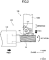
Fig. 2 is a diagram illustrating the relationship between a workpiece and a multi-blade tool. -
Fig. 3 is a diagram illustrating the multi-blade tool. -
Fig. 4 is a diagram illustrating the time-series operation (in the first pass) of the threading. -
Fig. 5 is a diagram illustrating the time-series operation (in the second pass) of the threading. -
Fig. 6 is a diagram illustrating the time-series operation (in the final pass) of the threading. -
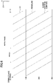
Fig. 7 is a diagram illustrating the tool locus (in the first pass). -
Fig. 8 is a diagram illustrating the tool locus (in the second pass). -
Fig. 9 is a diagram illustrating the tool locus (in the final path). - Hereinafter, a machining device, a machining method and a cutting tool according to the present invention will be described with reference to drawings. As shown in
Fig. 1 , amachine tool 100 includes aspindle 110, atool post 130A and acontrol device 180. Themachine tool 100 corresponds to the machining device of the present invention. - A
chuck 120 is provided at the end of thespindle 110, and the workpiece W is held by thespindle 110 via thechuck 120. Thespindle 110 corresponds to a workpiece holding means. Thespindle 110 is rotatably supported by aspindle headstock 110A and rotationally driven by the power of a spindle motor 115 (for example, a built-in motor) provided between thespindle headstock 110A and thespindle 110, for example. - The
spindle headstock 110A is installed on a Z-axisdirection feeding mechanism 160. - The Z-axis
direction feeding mechanism 160 includes abase 161 integral with a bed, and a Z-axisdirection guide rail 162 slidably supporting a Z-axis direction feeding table 163. When the Z-axis direction feeding table 163 is moved by the drive of alinear servomotor 165 along the Z-axis direction shown in the figure which coincides with the rotational axis direction of the workpiece W, thespindle headstock 110A moves in the Z-axis direction. Thelinear servomotor 165 has amover 165a and astator 165b. Themover 165a is provided on the Z-axis direction feeding table 163, and thestator 165b is provided on thebase 161. - A
cutting tool 130 such as a tool bit for turning a workpiece W is mounted on thetool post 130A, and thetool post 130A is installed on an X-axisdirection feeding mechanism 150. - The X-axis
direction feeding mechanism 150 includes abase 151 integral with a bed, and an X-axisdirection guide rail 152 slidably supporting an X-axis direction feeding table 153. When the X-axis direction feeding table 153 is moved along the X-axis direction orthogonal to the Z-axis direction shown in the figure by the drive of alinear servomotor 155, thetool post 130A moves in the X-axis direction. Thelinear servomotor 155 has a mover 155a and a stator 155b. Themover 155a is provided on the X-axis direction feeding table 153, and the stator 155b is provided on thebase 151. - A Y-axis direction feeding mechanism may be provided in the
machine tool 100. The Y-axis direction is a direction orthogonal to the Z-axis direction and the X-axis direction shown in the figure. The Y-axis direction feeding mechanism may have the same structure as the Z-axisdirection feeding mechanism 160 or the X-axisdirection feeding mechanism 150. As is conventionally known, thecutting tool 130 can be moved in the Y-axis direction in addition to the X-axis direction by a combination of the X-axisdirection feeding mechanism 150 and the Y-axis direction feeding mechanism. - Although the Z-axis
direction feeding mechanism 160, the X-axisdirection feeding mechanism 150 and the Y-axis direction feeding mechanism have been described with an example using a linear servomotor, a known ball screw and servomotor may be used. - The rotation of the
spindle 110, the movements of the Z-axisdirection feeding mechanism 160, the X-axisdirection feeding mechanism 150 and the like are controlled by acontrol section 181. - The
control section 181 is composed of a CPU, a memory or the like, loads various programs and data which are stored in a ROM or the like into a RAM, and executes the program. Thereby, the operation of themachine tool 100 can be controlled on the basis of the program. - In the example of
Fig. 1 , thecontrol section 181 drives thespindle motor 115 to rotate the workpiece W relative to thecutting tool 130 and drives the Z-axisdirection feeding mechanism 160 to move the workpiece W relative to thecutting tool 130 in the Z-axis direction. Further, the X-axisdirection feeding mechanism 150 is driven to reciprocally vibrate thecutting tool 130 relative to the workpiece W in the X-axis direction to perform multiple times of cutting along the same cutting path in a predetermined spiral form. Thereby, a threaded portion is machined on the workpiece W by thecutting tool 130 as shown inFig. 2 . - The
cutting tool 130 has aholder 130B held by thetool post 130A, and for example, atip 131 for machining the workpiece W to form an external screw is screwed to the end of theholder 130B. - As shown in
Fig. 3 , thetip 131 has a toolmain body 132 formed in a prismatic shape, and athrough hole 133, through which a screw for clamping thetip 131 to theholder 130B is inserted, is formed at the center of the toolmain body 132. A set of (for example, two) cutting blades (afront blade 141 and a rear blade 142) is formed on the outer periphery of the toolmain body 132. Thefront blade 141 corresponds to a first cutting blade, and therear blade 142 corresponds to a second cutting blade. As described above, thetip 131 has a plurality of cutting blades and corresponds to a multi-blade tool for cutting the workpiece W. Three sets of thefront blade 141 and therear blade 142 are provided on the outer periphery of the toolmain body 132, and are arranged at equal intervals from each other. - The
front blade 141 and therear blade 142 are arranged side by side along the feed direction (Z-axis direction inFig. 2 ), and thefront blade 141 is located in front of (in the positive direction in the Z-axis and the same direction as the arrow of Z-axis, and the same is applied hereinafter) therear blade 142. Thefront blade 141 and therear blade 142 are formed in the same shape as the thread groove to be machined, and the distance between thefront blade 141 and therear blade 142 is determined based on the pitch of the thread portion to be machined. - Further, in a case where the cutting edges of the
front blade 141 and therear blade 142 are arranged so as to face the positive direction in the X axis inFig. 2 (the same direction as the arrow of the X axis and the same is applied hereinafter) and where the workpiece W is fed in the negative direction in the Z axis inFig. 2 (the opposite direction to the arrow of the Z axis, and the same is applied hereinafter) and rotated from the back side toward the forward side shown by the arrow inFig. 2 in a state where the workpiece W is in contact with the cutting edges of thefront blade 141 and therear blade 142, a right threaded screw is formed on the workpiece W. - If a left threaded screw is to be formed on the workpiece W, the cutting edges of the
front blade 141 and therear blade 142 are arranged so as to face the negative direction in the X-axis inFig. 2 (the direction opposite to the arrow of the X-axis, and the same is applied hereinafter), and the workpiece W is fed in the negative direction in the Z axis ofFig. 2 and rotated in the direction opposite to the arrow inFig. 2 . - When threading the workpiece W, the
control section 181 sets the number of cuttings to (for example) five, as illustrated inFigs. 4 to 9 , and the workpiece is cut five times in a spiral form to form a threaded portion. Here, the number of cuttings is the number of cuttings until the threaded portion is formed. - More specifically, for example, after four groove machining is performed, one finish machining is performed.
- First, the groove machining is a step of forming a threaded portion with vibration in the radial direction of the workpiece W (while reciprocally vibrating the
tip 131 relative to the workpiece W in the X-axis direction), and both of thefront blade 141 and therear blade 142 are used. -
Figs. 4 and7 are diagrams illustrating the first pass of the groove machining. The cutting edges of thefront blade 141 and therear blade 142 are arranged so as to face the positive direction in the X axis, and the machining time is set to 0 sec when therear blade 142 is at the position of Z = 0. At this point, the cutting edge of thefront blade 141 is located at point A inFig. 4 , and the cutting edge of therear blade 142 is located at point a inFig. 4 . - As the workpiece W rotates, the cutting edges move relatively in the negative direction in the Y axis in
Fig. 4 (the direction opposite to the arrow of the Y axis, and the same is applied hereinafter), and as the workpiece W is fed in the negative direction in the Z axis inFig. 2 , the cutting edges move in the positive direction in the Z axis inFig. 4 . Thefront blade 141 and therear blade 142 move (forward) in the radial direction of the workpiece W (positive direction in the X-axis: the back side of the paper surface) by a predetermined forward movement amount, and then move (backward) in the opposite direction by a predetermined backward movement amount. InFigs. 4 and7 , an example is used in which the number of vibrations D, which is the number of reciprocating movements of thecutting tool 130 in one rotation of the workpiece W, is 3 (times / r). - Particularly, the
rear blade 142 advances from the point a to the point b inFig. 4 to form a tool locus as a cutting mark t0. At that time, therear blade 142 is gradually pushed in the positive direction in the X axis from the point a, the cutting depth becomes the largest at the intermediate position between the points a and b, the cutting depth gradually decreases as approaching the point b, and then, therear blade 142 reaches the point b. - Due to the relative movement of the cutting edge, after the lapse of a predetermined time, the
rear blade 142 moves from the point b of the tool locus t0 to the point b of a tool locus t1. - After that, the
rear blade 142 moves from the point b of the tool locus t1 to the point c of the same t1. Also at that time, therear blade 142 is gradually pushed in the positive direction in the X axis from the point b, the cutting depth becomes the largest at the intermediate position between the points b and c, the cutting depth gradually decreases as approaching the point c, and then, therear blade 142 reaches the point c. After that, therear blade 142 moves in the order of tool loci t2, t3, t4, t5 and t6. - The
front blade 141 is at a position in front of therear blade 142 by one pitch. Therefore, while therear blade 142 is located on the tool locus t0, thefront blade 141 moves from the point A to the point B inFig. 4 to form a tool locus T0. At that time, thefront blade 141 is gradually pushed in the positive direction in the X axis from the point A, the cutting depth becomes the largest at the intermediate position between the points A and B, the cutting depth gradually decreases as approaching the point B, and then, thefront blade 141 reaches the point B. Due to the relative movement of the cutting edge, after the lapse of a predetermined time, thefront blade 141 moves from the point B of the tool locus T0 to the point B of a tool locus T1. After that, thefront blade 141 moves from the point B of the tool locus T1 to the point C of the same T1, and after that thefront blade 141 moves in the order of tool loci T2, T3, T4 and T5. - In the first pass, since the machining time is set to 0 sec when the
rear blade 142 is at the position of Z = 0, as shown inFig. 7 in which the vertical axis is the X-axis coordinate (cutting direction) and the horizontal axis is the lead direction, the tool locus t0 of therear blade 142 reciprocally vibrates so that the cutting is started from the position of the rear blade spindle phase = 0 (degree), and the tool locus t0 peaks at the position of the rear blade spindle phase = 60 (degrees) and the return movement starts. Then, the blade edge of therear blade 142 reaches the outer peripheral surface of the workpiece W at the position of the rear blade spindle phase = 120 (degrees). Next, the tool locus t1 of therear blade 142 reciprocally vibrates so that the cutting is started from the position of the rear blade spindle phase = 120 (degrees), and the blade edge of therear blade 142 reaches the outer peripheral surface of the workpiece W at the position of the rear blade spindle phase = 240 (degrees). - On the other hand, in the first pass, the
front blade 141 is at the position of the rear blade spindle phase = 60 (degrees) when therear blade 142 is at the position of Z = 0. Therefore, the tool locus T0 of thefront blade 141 reciprocally vibrates so that the cutting is started from the position of the rear blade spindle phase = 60 (degrees), which is the position of the front blade spindle phase = 0 (degree), and the tool locus T0 peaks at the position of the rear blade spindle phase = 120 (degrees), which is the position of the front blade spindle phase = 60 (degrees), and the return movement starts. Then, the blade edge of thefront blade 141 reaches the outer peripheral surface of the workpiece W at the position of the rear blade spindle phase = 180 (degrees), which is the position of the front blade spindle phase = 120 (degrees). - Therefore, as shown in
Fig. 7 , the tool locus of thefront blade 141 and the tool locus of therear blade 142 deviate from each other in the spindle phase (horizontal axis direction in the graph ofFig. 7 ), and the tool locus of thefront blade 141 and the tool locus of therear blade 142 overlap. During the overlapping period of the tool loci in which the tool locus t0 of therear blade 142 is included in the tool locus T0 of thefront blade 141, a portion of the workpiece W to be cut by therear blade 142 has already been cut by the front blade 141 (tool locus T0). Therefore, there is an air-cut period in which the rear blade 142 (tool locus t0) substantially does not cut the workpiece W, and a chip generated on the workpiece W is divided into segmented chips. After that, in the first pass, when therear blade 142 reaches the tool locus of thefront blade 141 in the return movement, chips are divided. -
Figs 5 and8 are diagrams illustrating the groove machining in the second pass. The cutting amount in the second pass is set to, for example, the same value as the cutting amount in the first pass, and the machining time is set to 0 sec when thefront blade 141 having the cutting edge facing the positive direction in the X axis is at the position of Z = 0. - The
front blade 141 moves in the order from the tool locus T0 to T1, T2, T3, T4, T5 and T6, and therear blade 142 is at the position of Z = 0 (indicated by the tool locus t3) at the time when thefront blade 141 is on the tool locus T3, and moves in the order of t4, t5, t6, t7 and t8. - In the second pass, the machining time is set to 0 sec when the
front blade 141 is at the position of Z = 0. Therefore, as shown inFig. 8 , the tool locus T0 of thefront blade 141 reciprocally vibrates so that the cutting starts from the position of the front blade spindle phase = 0 (degree), peaks at the position of the front blade spindle phase = 60 (degrees) and the return movement starts. Then, the tool locus T0 reaches the cut portion in the first pass (indicated by the broken line in the figure) before the front blade spindle phase = 120 (degrees). Next, the tool locus T1 of thefront blade 141 reciprocally vibrates so that the cutting starts from the position of the front blade spindle phase = 120 (degrees), and reaches the cut portion in the first pass before the front blade spindle phase = 240 (degrees). - Therefore, as shown in
Fig. 8 , the tool locus of thefront blade 141 and the cut portion in the first pass overlap. During the overlapping period of the tool loci in which the tool locus T0 of thefront blade 141 is included in the cut portion in the first pass, there is the air-cut period in which the front blade 141 (tool locus T0) substantially does not cut the workpiece W, and a chip generated on the workpiece W is divided into segmented chips. - On the other hand, in the second pass, the
rear blade 142 is at the position of Z = 0 (indicated by the tool locus t3) at the time when thefront blade 141 is in the tool locus T3. Therefore, the tool locus t3 of therear blade 142 reciprocally vibrates so that the cutting is started from the position of the front blade spindle phase = 300 (degrees), which is the position of the rear blade spindle phase = 0 (degree), and the tool locus t3 peaks at the position of the front blade spindle phase = 0 (degree), which is the position of the rear blade spindle phase = 60 (degrees), and the return movement starts. Then, the blade edge of therear blade 142 reaches the tool locus T3 of thefront blade 141 before the position of the front blade spindle phase = 60 (degrees), which is the position of the rear blade spindle phase = 120 (degrees). - Therefore, as shown in
Fig. 8 , the tool locus of thefront blade 141 and the tool locus of therear blade 142 overlap. During the overlapping period of the tool loci in which the tool locus t3 of therear blade 142 is included in the tool locus T3 of thefront blade 141, there is the air-cut period in which the rear blade 142 (tool locus t3) substantially does not cut the workpiece W, and a chip generated on the workpiece W is divided into segmented chips. After that, in the second pass, when thefront blade 141 reaches the cut portion in the first pass in the return movement thereof, or when therear blade 142 reaches the tool locus of thefront blade 141 in the return movement thereof, a chip is divided into segmented chips. - Further, although not shown, in this groove machining, in the third pass, for example, the machining time is set to 0 sec when the
rear blade 142 is at the position of Z = 0, and in the fourth pass, for example, the machining time is set to 0 sec when thefront blade 141 is at the position of Z =0. Further, for example, the cutting amount in the third pass and the cutting amount in the fourth pass are set to different values. That is, the cutting amount in the third pass is set to a value smaller than the cutting amount in the second pass, and the cutting amount in the fourth pass is set to a value smaller than the cutting amount in the third pass. - As a result, in the third pass, when the
rear blade 142 reaches the cut portion in the second pass, or when therear blade 142 reaches the tool locus of thefront blade 141, a chip is divided. Further, in the fourth pass, when thefront blade 141 reaches the cut portion in the third pass, or when therear blade 142 reaches the tool locus of thefront blade 141, a chip is divided. - While the above-described groove machining is a step of forming a thread portion with vibration in the radial direction of the workpiece W, a finish machining is a step of forming a threaded portion without vibration in the radial direction of the workpiece W, and in the finish machining, only the
front blade 141 is used and therear blade 142 is not used. Therefore, the length of therear blade 142 is set shorter than the length of thefront blade 141, and as shown inFig. 3 , the cutting edge of therear blade 142 is provided at a position lower than the cutting edge of thefront blade 141 by h. That is, in the groove machining with vibration, the cutting amount and the amplitude are adjusted so that thefront blade 141 and therear blade 142 are used to machine the workpiece W, and in the finish machining without vibration, only thefront blade 141 is used to machine the workpiece W. Thecontrol section 181 may set the amplitude of the vibration waveform to a value at which the cutting edge of therear blade 142 does not come into contact with the screw bottom surface of the workpiece W in the finish machining. The amplitude can be set, for example, by the ratio (amplitude cut ratio) to the actual cutting amount of the cutting tool with respect to the workpiece W. -
Figs. 6 and9 are diagrams illustrating the finish machining in the fifth pass. The cutting amount in the last fifth pass is set to a value smaller than the cutting amount in the fourth pass. In the fifth pass, since the workpiece W does not reciprocally vibrate in the radial direction, the cutting amount is a constant value as shown inFig. 9 . If the machining time is set to 0 sec when thefront blade 141 is at the position of Z = 0, the cutting edge of thefront blade 141 advances in contact with the screw bottom surface shown by the broken line inFig. 6 and cuts the workpiece W to form the screw bottom surface of the workpiece W. - As described above, in the finish machining, the cutting edge of the
rear blade 142 does not come into contact with the screw bottom surface of the workpiece W. Therefore, even if thread cutting is performed using thetip 131, a threaded portion with high machining accuracy can be formed. - Further, by adopting the
multi-blade tip 131, the number of passes can be reduced and the machining time can be shortened as compared with the case where the single cutting blade is used. Further, since therear blade 142 cuts the portion not cut by thefront blade 141 and thefront blade 141 cuts the portion not cut by therear blade 142, the cutting resistance generated per blade is reduced and the lives of the blades are extended. - In
Fig. 1 , the example is described in which thespindle motor 115 corresponds to a rotating means, the Z-axisdirection feeding mechanism 160 corresponds to a feeding means for moving thespindle 110 in the Z-axis direction (predetermined feed direction), and the X-axisdirection feeding mechanism 150 corresponds to a vibration means for reciprocally vibrating thecutting tool 130 in the X-axis direction on the basis of the set vibration waveform. However, the present invention is not limited to this example. For example, the vibration means may be installed separately from the X-axisdirection feeding mechanism 150. Further, thecutting tool 130 may be fed in the Z-axis direction, or thecutting tool 130 may be rotated while thespindle 110 is stopped. - Further, although the example has been described in which the cutting blade is composed of two blades with reference to the drawings, the cutting blade may be composed of three or more blades.
-
- 100
- machine tool (machining device)
- 110
- spindle (workpiece holding means)
- 110A
- spindle headstock
- 115
- spindle motor (rotating means)
- 120
- chuck
- 130
- cutting tool
- 130A
- tool post
- 130B
- holder
- 131
- tip (multi-blade tool)
- 132
- tool main body
- 133
- through hole
- 141
- front blade (first cutting blade)
- 142
- rear blade (second cutting blade)
- 150
- X-axis direction feeding mechanism (vibration means)
- 151
- base
- 152
- X-axis direction guide rail
- 153
- X-axis direction feeding table
- 154
- X-axis direction guide
- 155
- linear servomotor
- 155a
- mover
- 155b
- stator
- 160
- Z-axis direction feeding mechanism (feeding means)
- 161
- base
- 162
- Z-axis direction guide rail
- 163
- Z-axis direction feeding table
- 164
- Z-axis direction guide
- 165
- linear servomotor
- 165a
- mover
- 165b
- stator
- 180
- control device
- 181
- control section
- h
- length from the cutting edge of the front blade to the cutting edge of the rear blade
- T0 to T6
- tool locus of the front blade
- t0 to t8
- tool locus of the rear blade
- W
- workpiece
Claims (4)
- A machining device comprising:a workpiece holding means for holding a workpiece;a tool post for holding a multi-blade tool for cutting the workpiece;a feeding means for feeding the multi-blade tool in a predetermined feed direction relative to the workpiece via relative movement of the workpiece holding means and the tool post;a vibration means for relatively and reciprocally vibrating the workpiece holding means and the tool post in a radial direction of the workpiece; anda rotating means for relatively rotating the workpiece and the multi-blade tool,the multi-blade tool having a first cutting blade and a second cutting blade that are arranged side by side along the feed direction, the second cutting blade being located behind the first cutting blade and having length shorter than length of the first cutting blade, andthe machining device threading the workpiece to form a threaded portion on the workpiece by relatively rotating the workpiece and the multi-blade tool and relatively moving the workpiece and the multi-blade tool along the feed direction to perform multiple times of cutting processes in the radial direction of the workpiece along the same cutting path in a predetermined spiral form, whereinthe machining device includes a control section for controlling operations of the feeding means, the vibration means and the rotating means so that a groove machining to form the threaded portion with the vibration in the radial direction of the workpiece and a finish machining to form the threaded portion by bringing the multi-blade tool into contact with the grooved portion of the workpiece are performed, andthe control section sets amplitude of a vibration waveform, which is set for the vibration means, to a value at which a cutting edge of the second cutting blade does not come into contact with a screw bottom surface of the workpiece in the finish machining.
- The machining device according to claim 1, wherein the control section sets the amplitude of the vibration waveform, which is set for the vibration means, to ze ro in the finish machining.
- A machining method of threading a workpiece to form a threaded portion on the workpiece by relatively rotating the workpiece and a multi-blade tool for cutting the workpiece and relatively moving the workpiece and the multi-blade tool along a predetermined feed direction to perform multiple times of cutting processes in a ra dial direction of the workpiece along the same cutting path in a predetermined spir al form, whereinthe multi-blade tool has a first cutting blade and a second cutting blade tha t are arranged side by side along the feed direction, the second cutting blade is loc ated behind the first cutting blade and has length shorter than length of the first c utting blade,the threading includes a groove machining to form the threaded portion with relative and reciprocal vibration of the workpiece and the multi-blade tool in the r adial direction of the workpiece and a finish machining to form the threaded portio n by bringing the multi-blade tool into contact with the grooved portion of the work piece, andin the finish machining, amplitude of a vibration waveform, which is set for the reciprocal vibration, is set to a value at which a cutting edge of the second cutt ing blade does not come into contact with a screw bottom surface of the workpiece.
- A cutting tool used for a machining method of threading a workpiece to for m a threaded portion on the workpiece by relatively rotating the workpiece and a m ulti-blade tool for cutting the workpiece and relatively moving the workpiece and th e multi-blade tool along a predetermined feed direction to perform multiple times of cutting processes in a radial direction of the workpiece along the same cutting path in a predetermined spiral form, whereinthe threading includes a groove machining to form the threaded portion with relative and reciprocal vibration of the workpiece and the multi-blade tool in the r adial direction of the workpiece and a finish machining to form the threaded portio n by bringing the multi-blade tool into contact with the grooved portion of the work piece, andthe multi-blade tool has a first cutting blade, which is used for both of the groove machining and the finish machining, and a second cutting blade, which is loc ated behind the first cutting blade and used for only the groove machining, that are arranged side by side along the feed direction, and the second cutting blade has le ngth shorter than length of the first cutting blade.
Applications Claiming Priority (2)
| Application Number | Priority Date | Filing Date | Title |
|---|---|---|---|
| JP2019222601A JP7516035B2 (en) | 2019-12-10 | 2019-12-10 | Processing device, processing method, and cutting tool |
| PCT/JP2020/044415 WO2021117526A1 (en) | 2019-12-10 | 2020-11-30 | Processing device, processing method, and cutting tool |
Publications (2)
| Publication Number | Publication Date |
|---|---|
| EP4052821A1 true EP4052821A1 (en) | 2022-09-07 |
| EP4052821A4 EP4052821A4 (en) | 2023-11-15 |
Family
ID=76312580
Family Applications (1)
| Application Number | Title | Priority Date | Filing Date |
|---|---|---|---|
| EP20898876.6A Pending EP4052821A4 (en) | 2019-12-10 | 2020-11-30 | Processing device, processing method, and cutting tool |
Country Status (7)
| Country | Link |
|---|---|
| US (1) | US12337402B2 (en) |
| EP (1) | EP4052821A4 (en) |
| JP (1) | JP7516035B2 (en) |
| KR (1) | KR102923376B1 (en) |
| CN (1) | CN114787729B (en) |
| TW (1) | TWI878396B (en) |
| WO (1) | WO2021117526A1 (en) |
Families Citing this family (8)
| Publication number | Priority date | Publication date | Assignee | Title |
|---|---|---|---|---|
| JP6775237B2 (en) * | 2018-08-09 | 2020-10-28 | 国立大学法人東海国立大学機構 | Processing equipment and cutting method |
| JP7195110B2 (en) * | 2018-10-26 | 2022-12-23 | シチズン時計株式会社 | Machine tools and controllers |
| JP7214568B2 (en) * | 2019-05-29 | 2023-01-30 | シチズン時計株式会社 | Machine tools and controllers for these machine tools |
| DE112021003854T5 (en) * | 2020-07-17 | 2023-05-11 | Fanuc Corporation | Numerical control device and control method |
| CN113843458A (en) * | 2021-10-19 | 2021-12-28 | 清华大学 | Threading device |
| JP7827878B2 (en) * | 2022-09-30 | 2026-03-10 | ファナック株式会社 | Machine tool control device and machine tool display device |
| DE112023005891T5 (en) * | 2023-05-11 | 2025-12-24 | Fanuc Corporation | Display device for machine tool |
| CN119347325B (en) * | 2024-10-23 | 2025-08-01 | 丹东华强有色金属加工有限公司 | Copper-chromium-nickel-silicon alloy heat processing treatment process |
Family Cites Families (32)
| Publication number | Priority date | Publication date | Assignee | Title |
|---|---|---|---|---|
| DE2724808C3 (en) * | 1977-06-02 | 1980-01-17 | Purolator Filter Gmbh, 7110 Oehringen | Drive device for the cross-feed movement of the tool on devices for material-removing machining of turned parts |
| US4457065A (en) * | 1979-11-13 | 1984-07-03 | The Lodge & Shipley Company | Automatic tool changer for a lathe |
| GB8316428D0 (en) * | 1983-06-16 | 1983-07-20 | Ae Plc | Machine tools |
| US4635070A (en) | 1983-12-19 | 1987-01-06 | Granger Associates | Dual mode antenna having simultaneous operating modes |
| JPS60186103U (en) * | 1984-05-23 | 1985-12-10 | 宇野沢 敦夫 | Cutter for thread cutting |
| JP2878886B2 (en) * | 1991-12-26 | 1999-04-05 | 京セラ株式会社 | Double threaded indexable insert |
| JP3451800B2 (en) * | 1995-07-20 | 2003-09-29 | 三菱自動車工業株式会社 | Vibration cutting method |
| SE505157C2 (en) * | 1995-10-31 | 1997-07-07 | Seco Tools Ab | Method and cutting for threading |
| JP2002066809A (en) * | 2000-08-30 | 2002-03-05 | Kyocera Corp | Indexable inserts for thread cutting |
| US6592303B2 (en) | 2000-08-30 | 2003-07-15 | Kyocera Corporation | Throw-away tip |
| US7140812B2 (en) * | 2002-05-29 | 2006-11-28 | 3M Innovative Properties Company | Diamond tool with a multi-tipped diamond |
| US7445409B2 (en) * | 2005-10-19 | 2008-11-04 | 3M Innovative Properties Company | Cutting tool assembly including diamond cutting tips at half-pitch spacing for land feature creation |
| JP4819665B2 (en) * | 2006-12-18 | 2011-11-24 | オークマ株式会社 | Non-circular shape processing equipment |
| US7909546B2 (en) * | 2007-03-12 | 2011-03-22 | Mitsubishi Materials Corporation | Thread cutting insert |
| EP2698218A1 (en) * | 2012-08-17 | 2014-02-19 | Bühler GmbH | Tool, stencil, cartridge and method for corrugating a roller |
| US9352396B2 (en) * | 2013-03-05 | 2016-05-31 | Oberg Industries | Lathe for machining a workpiece and related methods and toolholders |
| US9931698B2 (en) * | 2013-05-20 | 2018-04-03 | Tungaloy Corporation | Cutting insert for threading, tool body and cutting tool |
| JP5666041B1 (en) * | 2013-10-17 | 2015-02-04 | 株式会社エムエイチセンター | R-θ table device and female thread processing device |
| ES2807617T3 (en) * | 2014-03-26 | 2021-02-23 | Citizen Watch Co Ltd | Control device for machine tools and machine tools provided with said control device |
| KR102343458B1 (en) * | 2014-03-26 | 2021-12-27 | 시티즌 도케이 가부시키가이샤 | Control device for machine tool, and machine tool provided with said control device |
| US9895749B2 (en) * | 2014-04-22 | 2018-02-20 | Daisho Seiki Corporation | Peeling machine |
| KR102288584B1 (en) * | 2014-08-29 | 2021-08-11 | 시티즌 도케이 가부시키가이샤 | Machine tool and control apparatus for machine tool |
| US11338404B2 (en) * | 2014-09-22 | 2022-05-24 | Citizen Watch Co., Ltd. | Machine tool and control apparatus of the machine tool |
| EP3205430B1 (en) * | 2014-10-08 | 2021-12-08 | Citizen Watch Co., Ltd. | Method for manufacturing a thread |
| EP3213848B1 (en) * | 2014-10-28 | 2024-09-18 | Mitsubishi Electric Corporation | Numerical control device |
| TWI693120B (en) * | 2015-09-10 | 2020-05-11 | 日商西鐵城時計股份有限公司 | Control device of machine tool and machine tool |
| ES3014626T3 (en) * | 2015-09-24 | 2025-04-23 | Citizen Watch Co Ltd | Machine tool control device, and machine tool equipped with said control device |
| TWI697379B (en) * | 2015-09-24 | 2020-07-01 | 日商西鐵城時計股份有限公司 | Control device of machine tool and machine tool provided with the control device |
| WO2018134924A1 (en) * | 2017-01-18 | 2018-07-26 | オーエスジー株式会社 | Thread milling cutter |
| JP2020066809A (en) | 2018-10-22 | 2020-04-30 | ブラザー工業株式会社 | Adhesive device |
| JP7264643B2 (en) * | 2019-01-10 | 2023-04-25 | シチズン時計株式会社 | Machine tool controls and machine tools |
| JP7214568B2 (en) * | 2019-05-29 | 2023-01-30 | シチズン時計株式会社 | Machine tools and controllers for these machine tools |
-
2019
- 2019-12-10 JP JP2019222601A patent/JP7516035B2/en active Active
-
2020
- 2020-11-30 US US17/784,014 patent/US12337402B2/en active Active
- 2020-11-30 EP EP20898876.6A patent/EP4052821A4/en active Pending
- 2020-11-30 WO PCT/JP2020/044415 patent/WO2021117526A1/en not_active Ceased
- 2020-11-30 CN CN202080084715.3A patent/CN114787729B/en active Active
- 2020-11-30 KR KR1020227018223A patent/KR102923376B1/en active Active
- 2020-11-30 TW TW109142062A patent/TWI878396B/en active
Also Published As
| Publication number | Publication date |
|---|---|
| CN114787729B (en) | 2025-05-09 |
| TW202122184A (en) | 2021-06-16 |
| EP4052821A4 (en) | 2023-11-15 |
| TWI878396B (en) | 2025-04-01 |
| KR102923376B1 (en) | 2026-02-05 |
| CN114787729A (en) | 2022-07-22 |
| KR20220104723A (en) | 2022-07-26 |
| WO2021117526A1 (en) | 2021-06-17 |
| JP2021092936A (en) | 2021-06-17 |
| US12337402B2 (en) | 2025-06-24 |
| US20230050486A1 (en) | 2023-02-16 |
| JP7516035B2 (en) | 2024-07-16 |
Similar Documents
| Publication | Publication Date | Title |
|---|---|---|
| US12337402B2 (en) | Machining device, machining method and cutting tool | |
| EP3603856B1 (en) | Control device for machine tool and machine tool | |
| EP3205430B1 (en) | Method for manufacturing a thread | |
| CN113168156B (en) | Machine tool control devices and machine tools | |
| JP6470085B2 (en) | Machine tool and control device for this machine tool | |
| JP7161349B2 (en) | Machine tool controls and machine tools | |
| TW201600219A (en) | Control device for machine tool, and machine tool provided with said control device | |
| JP5080120B2 (en) | Polygon processing apparatus and polygon processing method | |
| JP2018161735A (en) | Control device for machine tool and machine tool | |
| JP6517060B2 (en) | Machine tool and control device for the machine tool | |
| JP2016182654A (en) | Machine tool, and control device of machine tool | |
| JP4498631B2 (en) | Spindle movement type automatic lathe | |
| JP7057703B2 (en) | Machine Tools | |
| CN110682068A (en) | Method for machining large-helix precision gear through CNC slow-walking wire cutting | |
| JP2020013355A (en) | Control device of machine tool and machine tool | |
| CN208811554U (en) | Bracket for multi-shaft interlocked lathe | |
| JP3490129B2 (en) | Cutting method by numerically controlled machine tool | |
| JP2013078821A (en) | Machining apparatus |
Legal Events
| Date | Code | Title | Description |
|---|---|---|---|
| STAA | Information on the status of an ep patent application or granted ep patent |
Free format text: STATUS: THE INTERNATIONAL PUBLICATION HAS BEEN MADE |
|
| PUAI | Public reference made under article 153(3) epc to a published international application that has entered the european phase |
Free format text: ORIGINAL CODE: 0009012 |
|
| STAA | Information on the status of an ep patent application or granted ep patent |
Free format text: STATUS: REQUEST FOR EXAMINATION WAS MADE |
|
| 17P | Request for examination filed |
Effective date: 20220530 |
|
| AK | Designated contracting states |
Kind code of ref document: A1 Designated state(s): AL AT BE BG CH CY CZ DE DK EE ES FI FR GB GR HR HU IE IS IT LI LT LU LV MC MK MT NL NO PL PT RO RS SE SI SK SM TR |
|
| DAV | Request for validation of the european patent (deleted) | ||
| DAX | Request for extension of the european patent (deleted) | ||
| REG | Reference to a national code |
Ref country code: DE Ref legal event code: R079 Free format text: PREVIOUS MAIN CLASS: B23B0001000000 Ipc: B23B0027060000 |
|
| A4 | Supplementary search report drawn up and despatched |
Effective date: 20231016 |
|
| RIC1 | Information provided on ipc code assigned before grant |
Ipc: B23B 25/02 20060101ALI20231011BHEP Ipc: G05B 19/4093 20060101ALI20231011BHEP Ipc: B23G 5/00 20060101ALI20231011BHEP Ipc: B23B 27/06 20060101AFI20231011BHEP |