EP4051928B1 - Compact geared reduction unit for application with transmission shaft subjected to radial loads - Google Patents
Compact geared reduction unit for application with transmission shaft subjected to radial loads Download PDFInfo
- Publication number
- EP4051928B1 EP4051928B1 EP20792995.1A EP20792995A EP4051928B1 EP 4051928 B1 EP4051928 B1 EP 4051928B1 EP 20792995 A EP20792995 A EP 20792995A EP 4051928 B1 EP4051928 B1 EP 4051928B1
- Authority
- EP
- European Patent Office
- Prior art keywords
- transmission shaft
- reduction unit
- radial
- box
- bearings
- Prior art date
- Legal status (The legal status is an assumption and is not a legal conclusion. Google has not performed a legal analysis and makes no representation as to the accuracy of the status listed.)
- Active
Links
Images




Classifications
-
- F—MECHANICAL ENGINEERING; LIGHTING; HEATING; WEAPONS; BLASTING
- F16—ENGINEERING ELEMENTS AND UNITS; GENERAL MEASURES FOR PRODUCING AND MAINTAINING EFFECTIVE FUNCTIONING OF MACHINES OR INSTALLATIONS; THERMAL INSULATION IN GENERAL
- F16H—GEARING
- F16H57/00—General details of gearing
- F16H57/02—Gearboxes; Mounting gearing therein
- F16H57/025—Support of gearboxes, e.g. torque arms, or attachment to other devices
-
- F—MECHANICAL ENGINEERING; LIGHTING; HEATING; WEAPONS; BLASTING
- F03—MACHINES OR ENGINES FOR LIQUIDS; WIND, SPRING, OR WEIGHT MOTORS; PRODUCING MECHANICAL POWER OR A REACTIVE PROPULSIVE THRUST, NOT OTHERWISE PROVIDED FOR
- F03D—WIND MOTORS
- F03D15/00—Transmission of mechanical power
-
- F—MECHANICAL ENGINEERING; LIGHTING; HEATING; WEAPONS; BLASTING
- F03—MACHINES OR ENGINES FOR LIQUIDS; WIND, SPRING, OR WEIGHT MOTORS; PRODUCING MECHANICAL POWER OR A REACTIVE PROPULSIVE THRUST, NOT OTHERWISE PROVIDED FOR
- F03D—WIND MOTORS
- F03D80/00—Details, components or accessories not provided for in groups F03D1/00 - F03D17/00
- F03D80/70—Bearing or lubricating arrangements
-
- F—MECHANICAL ENGINEERING; LIGHTING; HEATING; WEAPONS; BLASTING
- F16—ENGINEERING ELEMENTS AND UNITS; GENERAL MEASURES FOR PRODUCING AND MAINTAINING EFFECTIVE FUNCTIONING OF MACHINES OR INSTALLATIONS; THERMAL INSULATION IN GENERAL
- F16C—SHAFTS; FLEXIBLE SHAFTS; ELEMENTS OR CRANKSHAFT MECHANISMS; ROTARY BODIES OTHER THAN GEARING ELEMENTS; BEARINGS
- F16C19/00—Bearings with rolling contact, for exclusively rotary movement
- F16C19/22—Bearings with rolling contact, for exclusively rotary movement with bearing rollers essentially of the same size in one or more circular rows, e.g. needle bearings
- F16C19/34—Bearings with rolling contact, for exclusively rotary movement with bearing rollers essentially of the same size in one or more circular rows, e.g. needle bearings for both radial and axial load
- F16C19/36—Bearings with rolling contact, for exclusively rotary movement with bearing rollers essentially of the same size in one or more circular rows, e.g. needle bearings for both radial and axial load with a single row of rollers
- F16C19/364—Bearings with rolling contact, for exclusively rotary movement with bearing rollers essentially of the same size in one or more circular rows, e.g. needle bearings for both radial and axial load with a single row of rollers with tapered rollers, i.e. rollers having essentially the shape of a truncated cone
-
- F—MECHANICAL ENGINEERING; LIGHTING; HEATING; WEAPONS; BLASTING
- F16—ENGINEERING ELEMENTS AND UNITS; GENERAL MEASURES FOR PRODUCING AND MAINTAINING EFFECTIVE FUNCTIONING OF MACHINES OR INSTALLATIONS; THERMAL INSULATION IN GENERAL
- F16C—SHAFTS; FLEXIBLE SHAFTS; ELEMENTS OR CRANKSHAFT MECHANISMS; ROTARY BODIES OTHER THAN GEARING ELEMENTS; BEARINGS
- F16C19/00—Bearings with rolling contact, for exclusively rotary movement
- F16C19/54—Systems consisting of a plurality of bearings with rolling friction
- F16C19/546—Systems with spaced apart rolling bearings including at least one angular contact bearing
- F16C19/547—Systems with spaced apart rolling bearings including at least one angular contact bearing with two angular contact rolling bearings
- F16C19/548—Systems with spaced apart rolling bearings including at least one angular contact bearing with two angular contact rolling bearings in O-arrangement
-
- F—MECHANICAL ENGINEERING; LIGHTING; HEATING; WEAPONS; BLASTING
- F16—ENGINEERING ELEMENTS AND UNITS; GENERAL MEASURES FOR PRODUCING AND MAINTAINING EFFECTIVE FUNCTIONING OF MACHINES OR INSTALLATIONS; THERMAL INSULATION IN GENERAL
- F16H—GEARING
- F16H1/00—Toothed gearings for conveying rotary motion
- F16H1/28—Toothed gearings for conveying rotary motion with gears having orbital motion
-
- F—MECHANICAL ENGINEERING; LIGHTING; HEATING; WEAPONS; BLASTING
- F16—ENGINEERING ELEMENTS AND UNITS; GENERAL MEASURES FOR PRODUCING AND MAINTAINING EFFECTIVE FUNCTIONING OF MACHINES OR INSTALLATIONS; THERMAL INSULATION IN GENERAL
- F16H—GEARING
- F16H57/00—General details of gearing
- F16H57/02—Gearboxes; Mounting gearing therein
- F16H57/021—Shaft support structures, e.g. partition walls, bearing eyes, casing walls or covers with bearings
-
- F—MECHANICAL ENGINEERING; LIGHTING; HEATING; WEAPONS; BLASTING
- F16—ENGINEERING ELEMENTS AND UNITS; GENERAL MEASURES FOR PRODUCING AND MAINTAINING EFFECTIVE FUNCTIONING OF MACHINES OR INSTALLATIONS; THERMAL INSULATION IN GENERAL
- F16H—GEARING
- F16H57/00—General details of gearing
- F16H57/02—Gearboxes; Mounting gearing therein
- F16H57/029—Gearboxes; Mounting gearing therein characterised by means for sealing the gearboxes, e.g. to improve airtightness
-
- F—MECHANICAL ENGINEERING; LIGHTING; HEATING; WEAPONS; BLASTING
- F16—ENGINEERING ELEMENTS AND UNITS; GENERAL MEASURES FOR PRODUCING AND MAINTAINING EFFECTIVE FUNCTIONING OF MACHINES OR INSTALLATIONS; THERMAL INSULATION IN GENERAL
- F16H—GEARING
- F16H57/00—General details of gearing
- F16H57/04—Features relating to lubrication or cooling or heating
- F16H57/0401—Features relating to lubrication or cooling or heating using different fluids, e.g. a traction fluid for traction gearing and a lubricant for bearings or reduction gears
-
- F—MECHANICAL ENGINEERING; LIGHTING; HEATING; WEAPONS; BLASTING
- F16—ENGINEERING ELEMENTS AND UNITS; GENERAL MEASURES FOR PRODUCING AND MAINTAINING EFFECTIVE FUNCTIONING OF MACHINES OR INSTALLATIONS; THERMAL INSULATION IN GENERAL
- F16H—GEARING
- F16H57/00—General details of gearing
- F16H57/04—Features relating to lubrication or cooling or heating
- F16H57/0463—Grease lubrication; Drop-feed lubrication
- F16H57/0464—Grease lubrication
-
- F—MECHANICAL ENGINEERING; LIGHTING; HEATING; WEAPONS; BLASTING
- F16—ENGINEERING ELEMENTS AND UNITS; GENERAL MEASURES FOR PRODUCING AND MAINTAINING EFFECTIVE FUNCTIONING OF MACHINES OR INSTALLATIONS; THERMAL INSULATION IN GENERAL
- F16H—GEARING
- F16H57/00—General details of gearing
- F16H57/04—Features relating to lubrication or cooling or heating
- F16H57/0467—Elements of gearings to be lubricated, cooled or heated
- F16H57/0469—Bearings or seals
- F16H57/0471—Bearing
-
- F—MECHANICAL ENGINEERING; LIGHTING; HEATING; WEAPONS; BLASTING
- F16—ENGINEERING ELEMENTS AND UNITS; GENERAL MEASURES FOR PRODUCING AND MAINTAINING EFFECTIVE FUNCTIONING OF MACHINES OR INSTALLATIONS; THERMAL INSULATION IN GENERAL
- F16H—GEARING
- F16H57/00—General details of gearing
- F16H57/04—Features relating to lubrication or cooling or heating
- F16H57/048—Type of gearings to be lubricated, cooled or heated
- F16H57/0482—Gearings with gears having orbital motion
- F16H57/0486—Gearings with gears having orbital motion with fixed gear ratio
-
- F—MECHANICAL ENGINEERING; LIGHTING; HEATING; WEAPONS; BLASTING
- F16—ENGINEERING ELEMENTS AND UNITS; GENERAL MEASURES FOR PRODUCING AND MAINTAINING EFFECTIVE FUNCTIONING OF MACHINES OR INSTALLATIONS; THERMAL INSULATION IN GENERAL
- F16H—GEARING
- F16H57/00—General details of gearing
- F16H57/08—General details of gearing of gearings with members having orbital motion
-
- F—MECHANICAL ENGINEERING; LIGHTING; HEATING; WEAPONS; BLASTING
- F16—ENGINEERING ELEMENTS AND UNITS; GENERAL MEASURES FOR PRODUCING AND MAINTAINING EFFECTIVE FUNCTIONING OF MACHINES OR INSTALLATIONS; THERMAL INSULATION IN GENERAL
- F16H—GEARING
- F16H57/00—General details of gearing
- F16H57/08—General details of gearing of gearings with members having orbital motion
- F16H57/082—Planet carriers
-
- F—MECHANICAL ENGINEERING; LIGHTING; HEATING; WEAPONS; BLASTING
- F05—INDEXING SCHEMES RELATING TO ENGINES OR PUMPS IN VARIOUS SUBCLASSES OF CLASSES F01-F04
- F05B—INDEXING SCHEME RELATING TO WIND, SPRING, WEIGHT, INERTIA OR LIKE MOTORS, TO MACHINES OR ENGINES FOR LIQUIDS COVERED BY SUBCLASSES F03B, F03D AND F03G
- F05B2260/00—Function
- F05B2260/40—Transmission of power
- F05B2260/403—Transmission of power through the shape of the drive components
- F05B2260/4031—Transmission of power through the shape of the drive components as in toothed gearing
-
- F—MECHANICAL ENGINEERING; LIGHTING; HEATING; WEAPONS; BLASTING
- F16—ENGINEERING ELEMENTS AND UNITS; GENERAL MEASURES FOR PRODUCING AND MAINTAINING EFFECTIVE FUNCTIONING OF MACHINES OR INSTALLATIONS; THERMAL INSULATION IN GENERAL
- F16C—SHAFTS; FLEXIBLE SHAFTS; ELEMENTS OR CRANKSHAFT MECHANISMS; ROTARY BODIES OTHER THAN GEARING ELEMENTS; BEARINGS
- F16C19/00—Bearings with rolling contact, for exclusively rotary movement
- F16C19/54—Systems consisting of a plurality of bearings with rolling friction
- F16C19/56—Systems consisting of a plurality of bearings with rolling friction in which the rolling bodies of one bearing differ in diameter from those of another
-
- F—MECHANICAL ENGINEERING; LIGHTING; HEATING; WEAPONS; BLASTING
- F16—ENGINEERING ELEMENTS AND UNITS; GENERAL MEASURES FOR PRODUCING AND MAINTAINING EFFECTIVE FUNCTIONING OF MACHINES OR INSTALLATIONS; THERMAL INSULATION IN GENERAL
- F16C—SHAFTS; FLEXIBLE SHAFTS; ELEMENTS OR CRANKSHAFT MECHANISMS; ROTARY BODIES OTHER THAN GEARING ELEMENTS; BEARINGS
- F16C2361/00—Apparatus or articles in engineering in general
- F16C2361/61—Toothed gear systems, e.g. support of pinion shafts
-
- F—MECHANICAL ENGINEERING; LIGHTING; HEATING; WEAPONS; BLASTING
- F16—ENGINEERING ELEMENTS AND UNITS; GENERAL MEASURES FOR PRODUCING AND MAINTAINING EFFECTIVE FUNCTIONING OF MACHINES OR INSTALLATIONS; THERMAL INSULATION IN GENERAL
- F16H—GEARING
- F16H1/00—Toothed gearings for conveying rotary motion
- F16H1/28—Toothed gearings for conveying rotary motion with gears having orbital motion
- F16H1/46—Systems consisting of a plurality of gear trains each with orbital gears, i.e. systems having three or more central gears
-
- F—MECHANICAL ENGINEERING; LIGHTING; HEATING; WEAPONS; BLASTING
- F16—ENGINEERING ELEMENTS AND UNITS; GENERAL MEASURES FOR PRODUCING AND MAINTAINING EFFECTIVE FUNCTIONING OF MACHINES OR INSTALLATIONS; THERMAL INSULATION IN GENERAL
- F16H—GEARING
- F16H57/00—General details of gearing
- F16H57/02—Gearboxes; Mounting gearing therein
- F16H2057/02039—Gearboxes for particular applications
- F16H2057/02069—Gearboxes for particular applications for industrial applications
- F16H2057/02073—Reduction gearboxes for industry
-
- F—MECHANICAL ENGINEERING; LIGHTING; HEATING; WEAPONS; BLASTING
- F16—ENGINEERING ELEMENTS AND UNITS; GENERAL MEASURES FOR PRODUCING AND MAINTAINING EFFECTIVE FUNCTIONING OF MACHINES OR INSTALLATIONS; THERMAL INSULATION IN GENERAL
- F16H—GEARING
- F16H57/00—General details of gearing
- F16H57/08—General details of gearing of gearings with members having orbital motion
- F16H2057/085—Bearings for orbital gears
-
- F—MECHANICAL ENGINEERING; LIGHTING; HEATING; WEAPONS; BLASTING
- F16—ENGINEERING ELEMENTS AND UNITS; GENERAL MEASURES FOR PRODUCING AND MAINTAINING EFFECTIVE FUNCTIONING OF MACHINES OR INSTALLATIONS; THERMAL INSULATION IN GENERAL
- F16H—GEARING
- F16H57/00—General details of gearing
- F16H57/02—Gearboxes; Mounting gearing therein
- F16H57/031—Gearboxes; Mounting gearing therein characterised by covers or lids for gearboxes
-
- Y—GENERAL TAGGING OF NEW TECHNOLOGICAL DEVELOPMENTS; GENERAL TAGGING OF CROSS-SECTIONAL TECHNOLOGIES SPANNING OVER SEVERAL SECTIONS OF THE IPC; TECHNICAL SUBJECTS COVERED BY FORMER USPC CROSS-REFERENCE ART COLLECTIONS [XRACs] AND DIGESTS
- Y02—TECHNOLOGIES OR APPLICATIONS FOR MITIGATION OR ADAPTATION AGAINST CLIMATE CHANGE
- Y02E—REDUCTION OF GREENHOUSE GAS [GHG] EMISSIONS, RELATED TO ENERGY GENERATION, TRANSMISSION OR DISTRIBUTION
- Y02E10/00—Energy generation through renewable energy sources
- Y02E10/70—Wind energy
- Y02E10/72—Wind turbines with rotation axis in wind direction
Definitions
- the present invention relates to a compact geared reduction unit for application with transmission shaft subjected to radial loads.
- Geared reduction units which substantially comprise a casing for the containment of a gear system for transmitting the rotation between a driving shaft and a transmission shaft.
- reduction units are known the gear system of which comprises at least one epicyclic output reduction stage constituted by a driving sun gear which rotates about a main axis and by a ring gear which is integral with the casing, between which multiple planet gears are engaged which are carried in rotation about their respective longitudinal axes which are parallel to the main axis by a transmission planet carrier, which in turn rotates about said main axis and is integrally associated in rotation with the transmission shaft.
- the reduction unit is of the multistage type, upstream of said epicyclic output reduction stage it is possible to provide one or more reduction stages in series, of the epicyclic type and/or with parallel axes.
- the transmission shaft has at least one portion accommodated inside the casing that is supported in rotation by suitable rolling members, such as for example a pair of bearings, each one of which has the inner ring mounted on the transmission shaft and the outer ring accommodated in a corresponding seat formed within the casing.
- suitable rolling members such as for example a pair of bearings, each one of which has the inner ring mounted on the transmission shaft and the outer ring accommodated in a corresponding seat formed within the casing.
- reduction units having one or more epicyclic reduction stages of the above described type are applied, for example, in the rotary actuation systems of the nacelles of wind turbines.
- the transmission shaft of the reduction unit is integral in rotation with a pinion which meshes with a toothed center bearing which is integral with said nacelle, and a radial load applied to the transmission shaft is generated in the coupling between said elements.
- the transmission shaft substantially has a portion accommodated inside the casing along which it is possible to identify, in axial direction, an end region for coupling with the planet carrier, a region for coupling with said adjustment ring, and a region for coupling with the two bearings.
- Prior art document CN 105 090 450 B discloses a compact geared reduction unit comprising a box-like body, a gear system accommodated inside said box-like body, a driving shaft, a transmission shaft, an output reduction stage of the epicyclic type which comprises a driving sun gear which rotates about a main axis, a ring gear which is integrally associated with said box-like body, multiple planet gears which are engaged between said driving sun gear and said ring gear and which are supported in rotation about respective longitudinal axes which are parallel to said main axis, and a transmission planet carrier which supports in rotation said multiple planet gears and which in turn rotates about said main axis and is connected so as to be integral in rotation with said transmission shaft at a connection region such that rotary motion is transmitted from said driving shaft to said transmission shaft, wherein the reduction unit further comprises rolling means comprising a first radial bearing which is arranged interposed in a radial direction between said box-like body and said planet carrier and a second radial bearing which is arranged interposed
- the aim of the present invention is to eliminate the drawbacks mentioned above of the background art, devising a compact geared reduction unit for application with transmission shaft subjected to radial loads which allows to obtain a suitable rotational support of the transmission shaft even in the presence of radial loads applied in a cantilevered manner and, at the same time, to limit the longitudinal volume and the weight of the reduction unit.
- an object of the present invention is to reduce the production and logistics management costs both of the components and of the entire reduction unit.
- Another object of the present invention is to reduce the quantity of lubricating oil to be used in the reduction unit, so as to reduce further its weight and its operating costs.
- Another object of the present invention is to be easier to apply and install inside the complex machines in which it is to be applied.
- Another object of the present invention is to be versatile in use for the applications in which the transmission shaft is subjected to a cantilevered radial load, such as for example the rotary actuation units of the nacelles of wind turbines.
- Another object of the present invention is to have a structure that is simple, relatively easy to provide in practice, safe in use, effective in operation, and of relatively low cost.
- a compact geared reduction unit for application with transmission shaft subjected to radial loads is generally designated by the numeral 1.
- the reduction unit 1 comprises a substantially box-like body 2 inside which a gear system 3 is accommodated for the transmission of rotary motion from a driving shaft 4 to a transmission shaft 5.
- the substantially box-like body 2 consists of two half-shells 2a and 2b connected by threaded members 6. It is not excluded that the substantially box-like body 2 might be otherwise shaped and be constituted by two or more components otherwise shaped and mutually coupled.
- the driving shaft 4 is adapted to be connected directly or indirectly to rotary actuation means such as a conventional electric or hydraulic motor.
- the transmission shaft 5 has an end portion that protrudes outside the substantially box-like body 2 and is adapted to transmit the motion to a unit to be actuated rotationally.
- the transmission shaft 5 is associated so as to be integral in rotation with a toothed pinion 28 at the end portion designed to couple with a corresponding toothed member of the unit to be actuated rotationally for motion transmission.
- the pinion 28 is, preferably, formed so as to be integral with the transmission shaft 5, but it is not excluded that they might be provided in two separate parts rendered integral at least in rotation about the main axis A by virtue of mechanical connection means.
- the gear system 3 is provided with an output reduction stage 7 of the epicyclic type, which comprises a driving sun gear 8 which rotates about a main axis A and a ring gear 9 integrally associated with the substantially box-like body 2 and extended around said axis.
- Multiple planet gears 10 are engaged between the sun gear 8 and the ring gear 9 and are supported in rotation about respective longitudinal axes which are parallel to the main axis A by a transmission planet carrier 11, which in turn rotates about said main axis and is associated so as to be integral in rotation with the transmission shaft 5 at a connection region 12.
- the number and arrangement of the planet gears 10 can vary in relation to the size of the output reduction stage 7 that is optimum for the specific application.
- four planet gears 10 are provided which are angularly spaced in pairs by 90° around the main axis A.
- the gear system 3 is of the single-stage type.
- the output reduction stage 7 is interposed directly between the driving shaft 4 connected to the sun gear 8 and the transmission shaft 5 connected to the planet carrier 11.
- the gear system 3 can be of the multistage type.
- Said further reduction stages can be of the epicyclic type or with parallel axes.
- the gear system 3 is of the multistage type and provides for three further reduction stages 13a, 13b, 13c of the epicyclic type arranged in series between the driving shaft 4 and the output reduction stage 7.
- the driving shaft 4 and the transmission shaft 5 are aligned along the main axis A. It is not excluded, however, that the driving shaft 4 and the transmission shaft 5 might be parallel, but not aligned (if the gear system comprises one or more further reduction stages with parallel axes), i.e., at right angles or oblique to each other.
- the reduction unit 1 comprises, moreover, rolling means 14 adapted to bear radial loads associated with the transmission shaft 5 for the rotational guiding thereof.
- the rolling means 14 comprise a first radial bearing 15, which is interposed in a radial direction between the substantially box-like body 2 and the planet carrier 11, and a second radial bearing 16, which is interposed radially between the body and the transmission shaft 5, the first and second bearings 15 and 16 being arranged axially on opposite sides of the connection region 12.
- the first and second bearings 15 and 16 are of the type of radial bearings with conical rollers mounted in an O-shaped configuration (so-called back-to-back configuration).
- they might be, for example, of the type of radial bearings with cylindrical rollers, radial needle roller bearings, radial spherical roller bearings, radial toroidal roller bearing or radial ball bearings.
- first and the second bearings 15 and 16 allows to arrange the second bearing 16 proximate to the region of application of the radial load and to maintain an adequate distance in an axial direction between said bearings so as to obtain an optimum support of the transmission shaft 5, but with a reduced axial volume of the transmission shaft and of the substantially box-like body 2 with respect to known solutions.
- the planet carrier 11 of the output reduction stage 7 also cooperates in supporting the transmission shaft 5.
- the planet carrier 11 comprises a flange 17 which is extended around the main axis A and from which multiple pivots 18 for rotationally supporting respective planet gears 10 protrude in an axial direction on one side and a hub 19 for connection to the transmission shaft 4 which defines the connection region 12 protrudes on the other side.
- four pivots 18 are provided which are angularly spaced in pairs by 90° around the main axis A.
- a conventional bearing 29, for example of the roller type, is interposed between each pivot 18 and the corresponding planet gear 10.
- the planet carrier 11 has, therefore, a so-called configuration with cantilevered supported pivots 18.
- the hub 19 and the transmission shaft 5 are associated so as to be integral in rotation about the main axis A by virtue of connection means with splined profiles 20 provided at the connection region 12.
- connection means with splined profiles 20 provided at the connection region 12.
- alternative methods of mechanical connection of the hub 19 and the transmission shaft 5 known to the person skilled in the art are not excluded.
- the first bearing 15 is associated with the planet carrier 11 externally to the flange 17.
- the inner ring of the first bearing 15 is, therefore, keyed on the outer side wall of the flange 17.
- the flange 17 is provided with an axial hole 21 which extends along the main axis A and is provided internally with an annular protrusion 22 which protrudes toward said axis.
- the transmission shaft 5 is provided with an end shank 23 which is accommodated along the hole 21 and protrudes beyond the protrusion 22 inside the substantially box-like body 2.
- An adjustment ring 24 is also provided which is coupled to the shank 23 and is adapted to abut in an axial direction against the protrusion 22 in order to adjust the preloading of the bearings 15 and 16.
- the ring 24 is internally threaded and is coupled with a corresponding female thread formed on the cylindrical side wall of the shank 23.
- one or more rings 25 with calibrated thickness can be provided which are interposed in an axial direction between the ring 24 and the protrusion 22 in order to obtain the desired preloading of the bearings 15 and 16.
- hydraulic sealing means 26 of a known type which are interposed in a radial direction between the hub 19 and the substantially box-like body 2, in order to insulate the portion of the internal cavity of the body that accommodates the gear system 3 and the first bearing 15 and in which lubrication with oil of the moving members is provided, and a closure and sealing ring 27 of the Nilos type which is clamped between the transmission shaft 5, the second bearing 16 and the substantially box-like body 2, in order to limit the portion of the internal cavity of said body in which the second bearing 16 is accommodated and in which there is grease lubrication of the moving members.
- the reduction unit 1 can be applied in a unit for the rotary actuation about a vertical axis of the nacelle of a wind power mast, not shown.
- the reduction unit 1 constitutes a component of a complex machine and is installed with the main axis arranged vertically and with the pinion 28 arranged in an upper region and coupled with a toothed center bearing which is integral with the nacelle to be rotationally actuated.
- the radial load applied to the transmission shaft 5 originates from the reaction of the coupling between the pinion 28 and the center bearing.
- a radial load applied to the transmission shaft 5 is provided, such as for example units for the rotary actuation of cabs or accessories of work vehicles, such as baskets, cranes, concrete pumps, stationary cement mixers, stationary cranes, mobile cranes, mixer trucks, slurry mixers, mixers for biogas plants, mining machines, shredders or rolling mills.
- work vehicles such as baskets, cranes, concrete pumps, stationary cement mixers, stationary cranes, mobile cranes, mixer trucks, slurry mixers, mixers for biogas plants, mining machines, shredders or rolling mills.
- the reduction unit according to the invention allows to obtain a suitable rotary support of the transmission shaft even in the presence of radial loads and to contain the axial extension of the shaft, of the substantially box-like body in which it is partially accommodated and, therefore, of the reduction unit as a whole.
- the reduction unit according to the invention also has a low weight and therefore is easier to use and move, and also has lower production and operating costs and a lower consumption of lubricating oil than known solutions.
- the reduction unit according to the invention is versatile in use and can be configured and sized according to the requirements of the specific application.
Landscapes
- Engineering & Computer Science (AREA)
- General Engineering & Computer Science (AREA)
- Mechanical Engineering (AREA)
- Life Sciences & Earth Sciences (AREA)
- Sustainable Development (AREA)
- Sustainable Energy (AREA)
- Chemical & Material Sciences (AREA)
- Combustion & Propulsion (AREA)
- Retarders (AREA)
- General Details Of Gearings (AREA)
- Gear Transmission (AREA)
- Wind Motors (AREA)
Description
- The present invention relates to a compact geared reduction unit for application with transmission shaft subjected to radial loads.
- Geared reduction units are known which substantially comprise a casing for the containment of a gear system for transmitting the rotation between a driving shaft and a transmission shaft.
- In particular, reduction units are known the gear system of which comprises at least one epicyclic output reduction stage constituted by a driving sun gear which rotates about a main axis and by a ring gear which is integral with the casing, between which multiple planet gears are engaged which are carried in rotation about their respective longitudinal axes which are parallel to the main axis by a transmission planet carrier, which in turn rotates about said main axis and is integrally associated in rotation with the transmission shaft.
- If the reduction unit is of the multistage type, upstream of said epicyclic output reduction stage it is possible to provide one or more reduction stages in series, of the epicyclic type and/or with parallel axes.
- The transmission shaft has at least one portion accommodated inside the casing that is supported in rotation by suitable rolling members, such as for example a pair of bearings, each one of which has the inner ring mounted on the transmission shaft and the outer ring accommodated in a corresponding seat formed within the casing. By means of an adjustment ring screwed onto the transmission shaft it is possible to adjust the preloading of the bearings.
- In particular, for applications in which the transmission shaft is subjected not only to a bending moment but also to a radial load applied in a cantilevered manner, two bearings with conical rollers mounted in an O-shaped configuration (so-called back-to-back configuration) are generally used.
- Typically, reduction units having one or more epicyclic reduction stages of the above described type are applied, for example, in the rotary actuation systems of the nacelles of wind turbines. In this case, the transmission shaft of the reduction unit is integral in rotation with a pinion which meshes with a toothed center bearing which is integral with said nacelle, and a radial load applied to the transmission shaft is generated in the coupling between said elements.
- According to the above described configuration of components, the transmission shaft substantially has a portion accommodated inside the casing along which it is possible to identify, in axial direction, an end region for coupling with the planet carrier, a region for coupling with said adjustment ring, and a region for coupling with the two bearings.
- This solution of the known type has some drawbacks, which includes the fact that according to the configuration described above the choice of the dimensions of the longitudinal extension of the portion of transmission shaft accommodated inside the casing and accordingly also that of said casing, which cannot be reduced below certain values in order to avoid compromising the strength of the reduction unit, penalizes its performance in terms of volumes, weight and costs.
- In fact, as is known, the radial stress that bearings with conical rollers are capable of withstanding increases as the distance between them increases and as the distance between the largest of the bearings and the load application point decreases. For this reason, in choosing the dimensions of the reduction unit it is necessary to arrange one bearing proximate to the load application point and the other one at a distance sufficient to obtain the desired support.
- As the cantilevered radial load applied to the transmission shaft increases, therefore, said distance and, consequently, the length of the portion of the transmission shaft to be accommodated inside the casing and the longitudinal volume of said casing also increase. The result, therefore, is an increase of the longitudinal volume and of the overall weight of the reduction unit, a higher production and logistics management cost both of the individual components (transmission shaft and casing) and of the entire reduction unit, complications in the assembly of the reduction unit in the machine in which it is intended to be applied and an increase in the quantity of lubricating oil introduced in the casing to lubricate the moving components.
- Prior art document
CN 105 090 450 B discloses a compact geared reduction unit comprising a box-like body, a gear system accommodated inside said box-like body, a driving shaft, a transmission shaft, an output reduction stage of the epicyclic type which comprises a driving sun gear which rotates about a main axis, a ring gear which is integrally associated with said box-like body, multiple planet gears which are engaged between said driving sun gear and said ring gear and which are supported in rotation about respective longitudinal axes which are parallel to said main axis, and a transmission planet carrier which supports in rotation said multiple planet gears and which in turn rotates about said main axis and is connected so as to be integral in rotation with said transmission shaft at a connection region such that rotary motion is transmitted from said driving shaft to said transmission shaft, wherein the reduction unit further comprises rolling means comprising a first radial bearing which is arranged interposed in a radial direction between said box-like body and said planet carrier and a second radial bearing which is arranged interposed radially between said box-like body and said transmission shaft, the first and second radial bearings being arranged axially on opposite sides of said connection region. - The aim of the present invention is to eliminate the drawbacks mentioned above of the background art, devising a compact geared reduction unit for application with transmission shaft subjected to radial loads which allows to obtain a suitable rotational support of the transmission shaft even in the presence of radial loads applied in a cantilevered manner and, at the same time, to limit the longitudinal volume and the weight of the reduction unit.
- Within this aim, an object of the present invention is to reduce the production and logistics management costs both of the components and of the entire reduction unit.
- Another object of the present invention is to reduce the quantity of lubricating oil to be used in the reduction unit, so as to reduce further its weight and its operating costs.
- Another object of the present invention is to be easier to apply and install inside the complex machines in which it is to be applied.
- Another object of the present invention is to be versatile in use for the applications in which the transmission shaft is subjected to a cantilevered radial load, such as for example the rotary actuation units of the nacelles of wind turbines.
- Another object of the present invention is to have a structure that is simple, relatively easy to provide in practice, safe in use, effective in operation, and of relatively low cost.
- This aim and these and other objects that will become more apparent hereinafter are all achieved by a compact geared reduction unit for application with transmission shaft subjected to radial loads according to
claim 1 and optionally provided with the characteristics according to the dependent claims. - Further characteristics and advantages of the present invention will become better apparent from the detailed description of a preferred but not exclusive embodiment, of a compact geared reduction unit for application with transmission shaft subjected to radial loads, illustrated by way of nonlimiting example in the accompanying drawings, wherein:
-
Figure 1 is a front elevation view of a compact geared reduction unit for application with transmission shaft subjected to radial loads, according to the invention; -
Figure 2 is a sectional view of the reduction unit ofFigure 1 , taken along the plane II-II; -
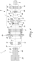
Figure 3 is an exploded lateral elevation view of a portion of the reduction unit according to the invention; -
Figure 4 is a sectional view ofFigure 3 , taken along the plane IV-IV; -
Figure 5 is a perspective view ofFigure 3 ; -
Figure 6 is a perspective view ofFigure 4 . - With particular reference to the figures, a compact geared reduction unit for application with transmission shaft subjected to radial loads is generally designated by the
numeral 1. - The
reduction unit 1 comprises a substantially box-like body 2 inside which agear system 3 is accommodated for the transmission of rotary motion from adriving shaft 4 to atransmission shaft 5. - In the embodiment shown, the substantially box-
like body 2 consists of two half-shells members 6. It is not excluded that the substantially box-like body 2 might be otherwise shaped and be constituted by two or more components otherwise shaped and mutually coupled. - In use, the
driving shaft 4 is adapted to be connected directly or indirectly to rotary actuation means such as a conventional electric or hydraulic motor. - The
transmission shaft 5 according to the invention has an end portion that protrudes outside the substantially box-like body 2 and is adapted to transmit the motion to a unit to be actuated rotationally. - In the embodiment shown, for example, the
transmission shaft 5 is associated so as to be integral in rotation with atoothed pinion 28 at the end portion designed to couple with a corresponding toothed member of the unit to be actuated rotationally for motion transmission. Thepinion 28 is, preferably, formed so as to be integral with thetransmission shaft 5, but it is not excluded that they might be provided in two separate parts rendered integral at least in rotation about the main axis A by virtue of mechanical connection means. - The
gear system 3 is provided with anoutput reduction stage 7 of the epicyclic type, which comprises a drivingsun gear 8 which rotates about a main axis A and aring gear 9 integrally associated with the substantially box-like body 2 and extended around said axis.Multiple planet gears 10 are engaged between thesun gear 8 and thering gear 9 and are supported in rotation about respective longitudinal axes which are parallel to the main axis A by atransmission planet carrier 11, which in turn rotates about said main axis and is associated so as to be integral in rotation with thetransmission shaft 5 at aconnection region 12. - The number and arrangement of the
planet gears 10 can vary in relation to the size of theoutput reduction stage 7 that is optimum for the specific application. In the embodiment shown, fourplanet gears 10 are provided which are angularly spaced in pairs by 90° around the main axis A. - In one possible embodiment the
gear system 3 is of the single-stage type. In this case theoutput reduction stage 7 is interposed directly between thedriving shaft 4 connected to thesun gear 8 and thetransmission shaft 5 connected to theplanet carrier 11. - As an alternative, the
gear system 3 can be of the multistage type. In this case there are one or further reduction stages arranged in series between thedriving shaft 4 and theoutput reduction stage 7. Said further reduction stages can be of the epicyclic type or with parallel axes. - In the embodiment shown in the figures, the
gear system 3 is of the multistage type and provides for threefurther reduction stages driving shaft 4 and theoutput reduction stage 7. - The
gear system 3 with the corresponding threefurther reduction stages - In this case, the
driving shaft 4 and thetransmission shaft 5 are aligned along the main axis A. It is not excluded, however, that thedriving shaft 4 and thetransmission shaft 5 might be parallel, but not aligned (if the gear system comprises one or more further reduction stages with parallel axes), i.e., at right angles or oblique to each other. - The
reduction unit 1 comprises, moreover, rollingmeans 14 adapted to bear radial loads associated with thetransmission shaft 5 for the rotational guiding thereof. - The rolling
means 14 comprise a firstradial bearing 15, which is interposed in a radial direction between the substantially box-like body 2 and theplanet carrier 11, and a secondradial bearing 16, which is interposed radially between the body and thetransmission shaft 5, the first andsecond bearings connection region 12. - In the embodiment shown, the first and
second bearings - The particular arrangement of the first and the
second bearings transmission shaft 5, but with a reduced axial volume of the transmission shaft and of the substantially box-like body 2 with respect to known solutions. - In this manner, the
planet carrier 11 of theoutput reduction stage 7 also cooperates in supporting thetransmission shaft 5. - In greater detail, the
planet carrier 11 comprises aflange 17 which is extended around the main axis A and from whichmultiple pivots 18 for rotationally supportingrespective planet gears 10 protrude in an axial direction on one side and ahub 19 for connection to thetransmission shaft 4 which defines theconnection region 12 protrudes on the other side. In the embodiment shown, fourpivots 18 are provided which are angularly spaced in pairs by 90° around the main axis A. - A
conventional bearing 29, for example of the roller type, is interposed between eachpivot 18 and thecorresponding planet gear 10. - The
planet carrier 11 has, therefore, a so-called configuration with cantilevered supportedpivots 18. - The
hub 19 and thetransmission shaft 5 are associated so as to be integral in rotation about the main axis A by virtue of connection means withsplined profiles 20 provided at theconnection region 12. However, alternative methods of mechanical connection of thehub 19 and thetransmission shaft 5 known to the person skilled in the art are not excluded. - The first bearing 15 is associated with the
planet carrier 11 externally to theflange 17. The inner ring of the first bearing 15 is, therefore, keyed on the outer side wall of theflange 17. - The
flange 17 is provided with anaxial hole 21 which extends along the main axis A and is provided internally with anannular protrusion 22 which protrudes toward said axis. - The
transmission shaft 5 is provided with anend shank 23 which is accommodated along thehole 21 and protrudes beyond theprotrusion 22 inside the substantially box-like body 2. - An
adjustment ring 24 is also provided which is coupled to theshank 23 and is adapted to abut in an axial direction against theprotrusion 22 in order to adjust the preloading of thebearings - The
ring 24 is internally threaded and is coupled with a corresponding female thread formed on the cylindrical side wall of theshank 23. - Furthermore, one or
more rings 25 with calibrated thickness can be provided which are interposed in an axial direction between thering 24 and theprotrusion 22 in order to obtain the desired preloading of thebearings - Furthermore, in the embodiment shown there are hydraulic sealing means 26 of a known type which are interposed in a radial direction between the
hub 19 and the substantially box-like body 2, in order to insulate the portion of the internal cavity of the body that accommodates thegear system 3 and thefirst bearing 15 and in which lubrication with oil of the moving members is provided, and a closure and sealingring 27 of the Nilos type which is clamped between thetransmission shaft 5, thesecond bearing 16 and the substantially box-like body 2, in order to limit the portion of the internal cavity of said body in which thesecond bearing 16 is accommodated and in which there is grease lubrication of the moving members. - It is not excluded that oil lubrication of all the moving members accommodated inside the substantially box-
like body 2 might be provided, and therefore the hydraulic sealing means 26 might be otherwise shaped and positioned. - In particular, the
reduction unit 1 can be applied in a unit for the rotary actuation about a vertical axis of the nacelle of a wind power mast, not shown. - In this case, the
reduction unit 1 constitutes a component of a complex machine and is installed with the main axis arranged vertically and with thepinion 28 arranged in an upper region and coupled with a toothed center bearing which is integral with the nacelle to be rotationally actuated. - In this case, the radial load applied to the
transmission shaft 5 originates from the reaction of the coupling between thepinion 28 and the center bearing. - However, alternative uses of the
reduction unit 1 are not excluded in applications in which a radial load applied to thetransmission shaft 5 is provided, such as for example units for the rotary actuation of cabs or accessories of work vehicles, such as baskets, cranes, concrete pumps, stationary cement mixers, stationary cranes, mobile cranes, mixer trucks, slurry mixers, mixers for biogas plants, mining machines, shredders or rolling mills. - In practice it has been found that the described invention achieves the intended aim and in particular it is noted that the reduction unit according to the invention allows to obtain a suitable rotary support of the transmission shaft even in the presence of radial loads and to contain the axial extension of the shaft, of the substantially box-like body in which it is partially accommodated and, therefore, of the reduction unit as a whole.
- Accordingly, the reduction unit according to the invention also has a low weight and therefore is easier to use and move, and also has lower production and operating costs and a lower consumption of lubricating oil than known solutions.
- Moreover, the reduction unit according to the invention is versatile in use and can be configured and sized according to the requirements of the specific application.
- The invention thus conceived is susceptible of numerous modifications and variations, all of which are within the scope of the appended claims.
- All the details may furthermore be replaced with other technically equivalent elements.
- In practice, the materials used, as well as the contingent shapes and dimensions, may be any according to the requirements without thereby abandoning the protective scope of the claims that follow.
- Where technical features mentioned in any claim are followed by reference signs, those reference signs have been included for the sole purpose of increasing the intelligibility of the claims and accordingly, such reference signs do not have any limiting effect on the interpretation of each element identified by way of example by such reference signs.
Claims (12)
- A compact geared reduction unit (1) comprising:a box-like body (2),a gear system (3) accommodated inside said box-like body (2),a driving shaft (4),a transmission shaft (5), said transmission shaft (5) having an end portion that protrudes outside said box-like body (2) in an axial direction of said transmission shaft (5) so as to be adapted to transmit motion to a unit to be actuated rotationally,an output reduction stage (7) of the epicyclic type of the gear system (3) which comprises: a driving sun gear (8) which rotates about a main axis (A); a ring gear (9) which is integrally associated with said box-like body (2); multiple planet gears (10) which are engaged between said driving sun gear (8) and said ring gear (9) and which are supported in rotation about respective longitudinal axes which are parallel to said main axis (A); and a transmission planet carrier (11), which supports in rotation said multiple planet gears (10) and which in turn rotates about said main axis and is connected so as to be integral in rotation with said transmission shaft (5) at a connection region (12) such that rotary motion is transmitted from said driving shaft (4) to said transmission shaft (5),the reduction unit (1) further comprising rolling means (14) comprising a first radial bearing (15) which is arranged interposed in a radial direction between said box-like body (2) and said planet carrier (11) and a second radial bearing (16) which is arranged interposed radially between said box-like body (2) and said transmission shaft (5), the first and second radial bearings (15, 16) being arranged axially on opposite sides of said connection region (12) such that said rolling means (14) being adapted to support cantilevered radial loads subjected to said transmission shaft (5) by a reaction of a coupling of said end portion of said transmission shaft (5) protruding outside said box-like body (2) to said unit to be actuated rotationally for the rotational guiding of said transmission shaft (5).
- The reduction unit (1) according to claim 1, characterized in that said planet carrier (11) comprises a flange (17) which is arranged extended around said main axis (A) and from which multiple pivots (18) for rotationally supporting respective said planet gears (10) protrude in an axial direction on one side and a hub (19) connected to said transmission shaft (5) which defines said connection region (12) protrudes on the other side.
- The reduction unit (1) according to claim 2, characterized in that said hub (19) and said transmission shaft (5) are mutually connected so as to be integral in rotation about said main axis (A) by connection means with splined profiles (20).
- The reduction unit (1) according to claim 2, characterized in that said first bearing (15) is connected with said planet carrier (11) externally to said flange (17).
- The reduction unit (1) according to claim 2, characterized in that said flange (17) is provided with an axial hole (21) which extends along said main axis (A) and is provided internally with an annular protrusion (22) which protrudes toward said axis and in that said transmission shaft (5) comprises a shank (23) which is accommodated along said hole (21) and protrudes beyond said protrusion (22), the reduction unit (1) further comprising an adjustment ring (24) which is coupled to said shank (23) so as to abut in an axial direction against said protrusion (22).
- The reduction unit (1) according to claim 5, characterized in that it comprises at least one ring (25) interposed in an axial direction between said adjustment ring (24) and said protrusion (22).
- The reduction unit (1) according to claim 2, characterized in that it comprises hydraulic sealing means (26) interposed in a radial direction between said hub (19) and said box-like body (2) and arranged in an axial direction between said first and second bearings (15, 16).
- The reduction unit (1) according to claim 2, characterized in that it comprises a closure and sealing ring (27) which is clamped between said transmission shaft (5), said second bearing (16) and said box-like body (2).
- The reduction unit (1) according to claim 1, characterized in that said first and second radial bearings (15, 16) are alternatively of the type of radial bearings with conical rollers mounted in an O-shaped configuration, radial bearings with cylindrical rollers, radial needle roller bearings, radial spherical roller bearings, radial toroidal roller bearings, radial ball bearings.
- The reduction unit (1) according to claim 1, characterized in that said transmission shaft (5) comprises a toothed pinion (28) which is integrally connected in rotation about the main axis (A) with said transmission shaft (5) and is arranged outside said box-like body (2).
- The reduction unit (1) according to claim 1, characterized in that said gear system (3) comprises at least one further reduction stage (13a, 13b, 13c) which is interposed between said driving shaft (4) and said output reduction stage (7), the at least one further reduction stage (13a, 13b, 13c) being of the epicyclic type or of the type with parallel axes.
- An assembly comprising a reduction unit (1) according to claim 10 for the rotary actuation of a nacelle of a wind turbine.
Applications Claiming Priority (2)
| Application Number | Priority Date | Filing Date | Title |
|---|---|---|---|
| IT102019000020024A IT201900020024A1 (en) | 2019-10-30 | 2019-10-30 | COMPACT GEAR REDUCER UNIT FOR APPLICATIONS WITH OUTPUT SHAFT SUBJECT TO RADIAL LOADS. |
| PCT/EP2020/079777 WO2021083789A1 (en) | 2019-10-30 | 2020-10-22 | Compact geared reduction unit for application with transmission shaft subjected to radial loads |
Publications (3)
| Publication Number | Publication Date |
|---|---|
| EP4051928A1 EP4051928A1 (en) | 2022-09-07 |
| EP4051928C0 EP4051928C0 (en) | 2024-10-16 |
| EP4051928B1 true EP4051928B1 (en) | 2024-10-16 |
Family
ID=69743823
Family Applications (1)
| Application Number | Title | Priority Date | Filing Date |
|---|---|---|---|
| EP20792995.1A Active EP4051928B1 (en) | 2019-10-30 | 2020-10-22 | Compact geared reduction unit for application with transmission shaft subjected to radial loads |
Country Status (6)
| Country | Link |
|---|---|
| US (1) | US11959541B2 (en) |
| EP (1) | EP4051928B1 (en) |
| JP (1) | JP2022554081A (en) |
| CN (1) | CN114599901B (en) |
| IT (1) | IT201900020024A1 (en) |
| WO (1) | WO2021083789A1 (en) |
Family Cites Families (16)
| Publication number | Priority date | Publication date | Assignee | Title |
|---|---|---|---|---|
| US3352178A (en) * | 1965-11-15 | 1967-11-14 | Gen Motors Corp | Planetary gearing |
| DE3048922A1 (en) * | 1980-12-22 | 1982-07-01 | Mannesmann AG, 4000 Düsseldorf | CONNECTION OF A TURNA HUB TO THE DRIVE GEAR OF A CHAIN VEHICLE |
| JPS57107055U (en) * | 1980-12-24 | 1982-07-01 | ||
| JPH0960711A (en) * | 1995-08-28 | 1997-03-04 | Shin Caterpillar Mitsubishi Ltd | Lubrication device for planetary gear reducer |
| DE10064815A1 (en) * | 2000-12-22 | 2002-07-11 | Zahnradfabrik Friedrichshafen | planetary gear |
| US6890282B2 (en) * | 2003-06-11 | 2005-05-10 | Zf Friedrichshafen Ag | Driveline for mobile vehicles |
| GB201104455D0 (en) * | 2011-03-16 | 2011-04-27 | Romax Technology Ltd | Cover and sealing arrangements for a wind turbine gearbox |
| EP2508754B1 (en) * | 2011-04-04 | 2016-03-30 | Siemens Aktiengesellschaft | Drive system for a wind turbine |
| WO2014069646A1 (en) * | 2012-11-05 | 2014-05-08 | 住友重機械工業株式会社 | Simple planetary reduction gear |
| EP2811625A1 (en) * | 2013-06-04 | 2014-12-10 | Brevini Power Transmission S.p.A. | Gearmotor with reduced axial space requirement |
| JP5877222B2 (en) * | 2014-05-30 | 2016-03-02 | 住友重機械工業株式会社 | Power transmission device for wind power generation equipment |
| ES2716083T3 (en) * | 2014-11-07 | 2019-06-10 | Comer Ind Spa | Epicycloidal reduction unit for applications with an ascending output |
| CN105090450B (en) * | 2015-09-09 | 2017-06-27 | 黄安民 | Hub reduction device |
| CN106969134B (en) * | 2017-04-17 | 2023-05-12 | 中国第一汽车股份有限公司 | Bearing positioning pre-tightening adjustment and sealing structure for input end of middle bridge |
| CN206860840U (en) * | 2017-04-17 | 2018-01-09 | 中国第一汽车股份有限公司 | Jackshaft input end bearing positioning pretension adjustment and sealing structure |
| CN108644370A (en) * | 2018-06-28 | 2018-10-12 | 大连民族大学 | A kind of helical tooth planetary reduction gearbox of the electronic energy equation motorcycle races of FSEC |
-
2019
- 2019-10-30 IT IT102019000020024A patent/IT201900020024A1/en unknown
-
2020
- 2020-10-22 WO PCT/EP2020/079777 patent/WO2021083789A1/en not_active Ceased
- 2020-10-22 CN CN202080074593.XA patent/CN114599901B/en active Active
- 2020-10-22 EP EP20792995.1A patent/EP4051928B1/en active Active
- 2020-10-22 JP JP2022522817A patent/JP2022554081A/en active Pending
- 2020-10-22 US US17/772,554 patent/US11959541B2/en active Active
Also Published As
| Publication number | Publication date |
|---|---|
| EP4051928A1 (en) | 2022-09-07 |
| CN114599901A (en) | 2022-06-07 |
| US20230012263A1 (en) | 2023-01-12 |
| WO2021083789A1 (en) | 2021-05-06 |
| JP2022554081A (en) | 2022-12-28 |
| EP4051928C0 (en) | 2024-10-16 |
| CN114599901B (en) | 2025-11-07 |
| US11959541B2 (en) | 2024-04-16 |
| IT201900020024A1 (en) | 2021-04-30 |
Similar Documents
| Publication | Publication Date | Title |
|---|---|---|
| EP3848214B1 (en) | Transaxle | |
| CA2356726C (en) | Transmission for wind generators | |
| US9435399B2 (en) | Reduction gear | |
| US10495185B2 (en) | Planetary wheel drive using bushings | |
| US10066735B1 (en) | Planetary wheel drive single wall lugged output carrier | |
| US7090465B2 (en) | Planet carrier assembly for wind turbine drive assembly | |
| US8591367B2 (en) | Non-backdrivable gear system | |
| US11078888B2 (en) | Wind turbine transmission | |
| US20150072821A1 (en) | Drive Unit with Drive Motor and Planetary Gear Mechanism | |
| US9316290B2 (en) | Epicyclic gearing with a gearing housing | |
| US11959541B2 (en) | Compact geared reduction unit for application with transmission shaft subjected to radial loads | |
| RU2347092C2 (en) | Gas turbine engine reducer | |
| WO2016016645A2 (en) | Gear mechanism | |
| US3439562A (en) | Speed-change mechanism | |
| RU2346172C2 (en) | Gas turbine engine reduction gear | |
| US10132372B2 (en) | Planetary wheel drive brake | |
| CN121002307A (en) | Planetary gearbox including the sun gear mounted in the planet carrier | |
| CN216692033U (en) | RV speed reduction transmission device and industrial robot | |
| CN100566082C (en) | High performance electromechanical driving mechanism | |
| CN114294377A (en) | RV speed reduction transmission device and industrial robot | |
| CN202883929U (en) | Planet type differential speed reducer | |
| JPH0341239A (en) | Epicycle reduction gear | |
| JP2016102535A (en) | Friction reduction gear | |
| CN223923718U (en) | Planetary reducer | |
| RU2464464C1 (en) | Electric drive with three-stage planetary reduction gear |
Legal Events
| Date | Code | Title | Description |
|---|---|---|---|
| STAA | Information on the status of an ep patent application or granted ep patent |
Free format text: STATUS: UNKNOWN |
|
| STAA | Information on the status of an ep patent application or granted ep patent |
Free format text: STATUS: THE INTERNATIONAL PUBLICATION HAS BEEN MADE |
|
| PUAI | Public reference made under article 153(3) epc to a published international application that has entered the european phase |
Free format text: ORIGINAL CODE: 0009012 |
|
| STAA | Information on the status of an ep patent application or granted ep patent |
Free format text: STATUS: REQUEST FOR EXAMINATION WAS MADE |
|
| 17P | Request for examination filed |
Effective date: 20220504 |
|
| AK | Designated contracting states |
Kind code of ref document: A1 Designated state(s): AL AT BE BG CH CY CZ DE DK EE ES FI FR GB GR HR HU IE IS IT LI LT LU LV MC MK MT NL NO PL PT RO RS SE SI SK SM TR |
|
| DAV | Request for validation of the european patent (deleted) | ||
| DAX | Request for extension of the european patent (deleted) | ||
| STAA | Information on the status of an ep patent application or granted ep patent |
Free format text: STATUS: EXAMINATION IS IN PROGRESS |
|
| 17Q | First examination report despatched |
Effective date: 20231218 |
|
| GRAP | Despatch of communication of intention to grant a patent |
Free format text: ORIGINAL CODE: EPIDOSNIGR1 |
|
| STAA | Information on the status of an ep patent application or granted ep patent |
Free format text: STATUS: GRANT OF PATENT IS INTENDED |
|
| RIC1 | Information provided on ipc code assigned before grant |
Ipc: F16C 19/56 20060101ALN20240430BHEP Ipc: F16C 19/54 20060101ALI20240430BHEP Ipc: F16C 19/36 20060101ALI20240430BHEP Ipc: F16H 1/46 20060101ALI20240430BHEP Ipc: F16H 57/031 20120101ALI20240430BHEP Ipc: F16H 57/08 20060101ALI20240430BHEP Ipc: F16H 57/04 20100101ALI20240430BHEP Ipc: F16H 57/021 20120101AFI20240430BHEP |
|
| INTG | Intention to grant announced |
Effective date: 20240516 |
|
| GRAS | Grant fee paid |
Free format text: ORIGINAL CODE: EPIDOSNIGR3 |
|
| GRAA | (expected) grant |
Free format text: ORIGINAL CODE: 0009210 |
|
| STAA | Information on the status of an ep patent application or granted ep patent |
Free format text: STATUS: THE PATENT HAS BEEN GRANTED |
|
| AK | Designated contracting states |
Kind code of ref document: B1 Designated state(s): AL AT BE BG CH CY CZ DE DK EE ES FI FR GB GR HR HU IE IS IT LI LT LU LV MC MK MT NL NO PL PT RO RS SE SI SK SM TR |
|
| REG | Reference to a national code |
Ref country code: GB Ref legal event code: FG4D |
|
| REG | Reference to a national code |
Ref country code: CH Ref legal event code: EP Ref country code: DE Ref legal event code: R096 Ref document number: 602020039613 Country of ref document: DE |
|
| REG | Reference to a national code |
Ref country code: IE Ref legal event code: FG4D |
|
| U01 | Request for unitary effect filed |
Effective date: 20241114 |
|
| U07 | Unitary effect registered |
Designated state(s): AT BE BG DE DK EE FI FR IT LT LU LV MT NL PT RO SE SI Effective date: 20241120 |
|
| U20 | Renewal fee for the european patent with unitary effect paid |
Year of fee payment: 5 Effective date: 20241127 |
|
| PG25 | Lapsed in a contracting state [announced via postgrant information from national office to epo] |
Ref country code: HR Free format text: LAPSE BECAUSE OF FAILURE TO SUBMIT A TRANSLATION OF THE DESCRIPTION OR TO PAY THE FEE WITHIN THE PRESCRIBED TIME-LIMIT Effective date: 20241016 Ref country code: IS Free format text: LAPSE BECAUSE OF FAILURE TO SUBMIT A TRANSLATION OF THE DESCRIPTION OR TO PAY THE FEE WITHIN THE PRESCRIBED TIME-LIMIT Effective date: 20250216 |
|
| PG25 | Lapsed in a contracting state [announced via postgrant information from national office to epo] |
Ref country code: ES Free format text: LAPSE BECAUSE OF FAILURE TO SUBMIT A TRANSLATION OF THE DESCRIPTION OR TO PAY THE FEE WITHIN THE PRESCRIBED TIME-LIMIT Effective date: 20241016 |
|
| PG25 | Lapsed in a contracting state [announced via postgrant information from national office to epo] |
Ref country code: NO Free format text: LAPSE BECAUSE OF FAILURE TO SUBMIT A TRANSLATION OF THE DESCRIPTION OR TO PAY THE FEE WITHIN THE PRESCRIBED TIME-LIMIT Effective date: 20250116 |
|
| PG25 | Lapsed in a contracting state [announced via postgrant information from national office to epo] |
Ref country code: GR Free format text: LAPSE BECAUSE OF FAILURE TO SUBMIT A TRANSLATION OF THE DESCRIPTION OR TO PAY THE FEE WITHIN THE PRESCRIBED TIME-LIMIT Effective date: 20250117 |
|
| PG25 | Lapsed in a contracting state [announced via postgrant information from national office to epo] |
Ref country code: PL Free format text: LAPSE BECAUSE OF FAILURE TO SUBMIT A TRANSLATION OF THE DESCRIPTION OR TO PAY THE FEE WITHIN THE PRESCRIBED TIME-LIMIT Effective date: 20241016 |
|
| PG25 | Lapsed in a contracting state [announced via postgrant information from national office to epo] |
Ref country code: RS Free format text: LAPSE BECAUSE OF FAILURE TO SUBMIT A TRANSLATION OF THE DESCRIPTION OR TO PAY THE FEE WITHIN THE PRESCRIBED TIME-LIMIT Effective date: 20250116 |
|
| REG | Reference to a national code |
Ref country code: CH Ref legal event code: PL |
|
| PG25 | Lapsed in a contracting state [announced via postgrant information from national office to epo] |
Ref country code: SM Free format text: LAPSE BECAUSE OF FAILURE TO SUBMIT A TRANSLATION OF THE DESCRIPTION OR TO PAY THE FEE WITHIN THE PRESCRIBED TIME-LIMIT Effective date: 20241016 |
|
| PG25 | Lapsed in a contracting state [announced via postgrant information from national office to epo] |
Ref country code: MC Free format text: LAPSE BECAUSE OF FAILURE TO SUBMIT A TRANSLATION OF THE DESCRIPTION OR TO PAY THE FEE WITHIN THE PRESCRIBED TIME-LIMIT Effective date: 20241016 |
|
| PG25 | Lapsed in a contracting state [announced via postgrant information from national office to epo] |
Ref country code: CH Free format text: LAPSE BECAUSE OF NON-PAYMENT OF DUE FEES Effective date: 20241031 |
|
| PG25 | Lapsed in a contracting state [announced via postgrant information from national office to epo] |
Ref country code: SK Free format text: LAPSE BECAUSE OF FAILURE TO SUBMIT A TRANSLATION OF THE DESCRIPTION OR TO PAY THE FEE WITHIN THE PRESCRIBED TIME-LIMIT Effective date: 20241016 |
|
| PG25 | Lapsed in a contracting state [announced via postgrant information from national office to epo] |
Ref country code: CZ Free format text: LAPSE BECAUSE OF FAILURE TO SUBMIT A TRANSLATION OF THE DESCRIPTION OR TO PAY THE FEE WITHIN THE PRESCRIBED TIME-LIMIT Effective date: 20241016 |
|
| PLBE | No opposition filed within time limit |
Free format text: ORIGINAL CODE: 0009261 |
|
| STAA | Information on the status of an ep patent application or granted ep patent |
Free format text: STATUS: NO OPPOSITION FILED WITHIN TIME LIMIT |
|
| 26N | No opposition filed |
Effective date: 20250717 |
|
| GBPC | Gb: european patent ceased through non-payment of renewal fee |
Effective date: 20250116 |
|
| PG25 | Lapsed in a contracting state [announced via postgrant information from national office to epo] |
Ref country code: GB Free format text: LAPSE BECAUSE OF NON-PAYMENT OF DUE FEES Effective date: 20250116 |
|
| PG25 | Lapsed in a contracting state [announced via postgrant information from national office to epo] |
Ref country code: IE Free format text: LAPSE BECAUSE OF NON-PAYMENT OF DUE FEES Effective date: 20241022 |
|
| U20 | Renewal fee for the european patent with unitary effect paid |
Year of fee payment: 6 Effective date: 20251020 |
|
| PG25 | Lapsed in a contracting state [announced via postgrant information from national office to epo] |
Ref country code: CY Free format text: LAPSE BECAUSE OF FAILURE TO SUBMIT A TRANSLATION OF THE DESCRIPTION OR TO PAY THE FEE WITHIN THE PRESCRIBED TIME-LIMIT; INVALID AB INITIO Effective date: 20201022 |
|
| PG25 | Lapsed in a contracting state [announced via postgrant information from national office to epo] |
Ref country code: HU Free format text: LAPSE BECAUSE OF FAILURE TO SUBMIT A TRANSLATION OF THE DESCRIPTION OR TO PAY THE FEE WITHIN THE PRESCRIBED TIME-LIMIT; INVALID AB INITIO Effective date: 20201022 |
|
| PG25 | Lapsed in a contracting state [announced via postgrant information from national office to epo] |
Ref country code: TR Free format text: LAPSE BECAUSE OF FAILURE TO SUBMIT A TRANSLATION OF THE DESCRIPTION OR TO PAY THE FEE WITHIN THE PRESCRIBED TIME-LIMIT Effective date: 20241016 |