EP4051588B1 - Emergency passage door - Google Patents
Emergency passage door Download PDFInfo
- Publication number
- EP4051588B1 EP4051588B1 EP20816582.9A EP20816582A EP4051588B1 EP 4051588 B1 EP4051588 B1 EP 4051588B1 EP 20816582 A EP20816582 A EP 20816582A EP 4051588 B1 EP4051588 B1 EP 4051588B1
- Authority
- EP
- European Patent Office
- Prior art keywords
- door
- moveable
- assembly
- passenger
- force
- Prior art date
- Legal status (The legal status is an assumption and is not a legal conclusion. Google has not performed a legal analysis and makes no representation as to the accuracy of the status listed.)
- Active
Links
Images






Classifications
-
- B—PERFORMING OPERATIONS; TRANSPORTING
- B64—AIRCRAFT; AVIATION; COSMONAUTICS
- B64D—EQUIPMENT FOR FITTING IN OR TO AIRCRAFT; FLIGHT SUITS; PARACHUTES; ARRANGEMENT OR MOUNTING OF POWER PLANTS OR PROPULSION TRANSMISSIONS IN AIRCRAFT
- B64D11/00—Passenger or crew accommodation; Flight-deck installations not otherwise provided for
- B64D11/06—Arrangements of seats, or adaptations or details specially adapted for aircraft seats
- B64D11/0606—Arrangements of seats, or adaptations or details specially adapted for aircraft seats with privacy shells, screens, separators or the like
-
- B—PERFORMING OPERATIONS; TRANSPORTING
- B64—AIRCRAFT; AVIATION; COSMONAUTICS
- B64D—EQUIPMENT FOR FITTING IN OR TO AIRCRAFT; FLIGHT SUITS; PARACHUTES; ARRANGEMENT OR MOUNTING OF POWER PLANTS OR PROPULSION TRANSMISSIONS IN AIRCRAFT
- B64D11/00—Passenger or crew accommodation; Flight-deck installations not otherwise provided for
- B64D11/0023—Movable or removable cabin dividers, e.g. for class separation
-
- E—FIXED CONSTRUCTIONS
- E05—LOCKS; KEYS; WINDOW OR DOOR FITTINGS; SAFES
- E05C—BOLTS OR FASTENING DEVICES FOR WINGS, SPECIALLY FOR DOORS OR WINDOWS
- E05C19/00—Other devices specially designed for securing wings, e.g. with suction cups
- E05C19/02—Automatic catches, i.e. released by pull or pressure on the wing
- E05C19/04—Ball or roller catches
-
- E—FIXED CONSTRUCTIONS
- E05—LOCKS; KEYS; WINDOW OR DOOR FITTINGS; SAFES
- E05D—HINGES OR SUSPENSION DEVICES FOR DOORS, WINDOWS OR WINGS
- E05D15/00—Suspension arrangements for wings
- E05D15/06—Suspension arrangements for wings for wings sliding horizontally more or less in their own plane
- E05D15/0621—Details, e.g. suspension or supporting guides
- E05D15/0626—Details, e.g. suspension or supporting guides for wings suspended at the top
- E05D15/063—Details, e.g. suspension or supporting guides for wings suspended at the top on wheels with fixed axis
-
- E—FIXED CONSTRUCTIONS
- E05—LOCKS; KEYS; WINDOW OR DOOR FITTINGS; SAFES
- E05B—LOCKS; ACCESSORIES THEREFOR; HANDCUFFS
- E05B65/00—Locks or fastenings for special use
- E05B65/08—Locks or fastenings for special use for sliding wings
-
- E—FIXED CONSTRUCTIONS
- E05—LOCKS; KEYS; WINDOW OR DOOR FITTINGS; SAFES
- E05C—BOLTS OR FASTENING DEVICES FOR WINGS, SPECIALLY FOR DOORS OR WINDOWS
- E05C19/00—Other devices specially designed for securing wings, e.g. with suction cups
- E05C19/02—Automatic catches, i.e. released by pull or pressure on the wing
-
- E—FIXED CONSTRUCTIONS
- E05—LOCKS; KEYS; WINDOW OR DOOR FITTINGS; SAFES
- E05Y—INDEXING SCHEME ASSOCIATED WITH SUBCLASSES E05D AND E05F, RELATING TO CONSTRUCTION ELEMENTS, ELECTRIC CONTROL, POWER SUPPLY, POWER SIGNAL OR TRANSMISSION, USER INTERFACES, MOUNTING OR COUPLING, DETAILS, ACCESSORIES, AUXILIARY OPERATIONS NOT OTHERWISE PROVIDED FOR, APPLICATION THEREOF
- E05Y2201/00—Constructional elements; Accessories therefor
- E05Y2201/20—Brakes; Disengaging means; Holders; Stops; Valves; Accessories therefor
- E05Y2201/214—Disengaging means
-
- E—FIXED CONSTRUCTIONS
- E05—LOCKS; KEYS; WINDOW OR DOOR FITTINGS; SAFES
- E05Y—INDEXING SCHEME ASSOCIATED WITH SUBCLASSES E05D AND E05F, RELATING TO CONSTRUCTION ELEMENTS, ELECTRIC CONTROL, POWER SUPPLY, POWER SIGNAL OR TRANSMISSION, USER INTERFACES, MOUNTING OR COUPLING, DETAILS, ACCESSORIES, AUXILIARY OPERATIONS NOT OTHERWISE PROVIDED FOR, APPLICATION THEREOF
- E05Y2201/00—Constructional elements; Accessories therefor
- E05Y2201/60—Suspension or transmission members; Accessories therefor
- E05Y2201/622—Suspension or transmission members elements
- E05Y2201/64—Carriers
-
- E—FIXED CONSTRUCTIONS
- E05—LOCKS; KEYS; WINDOW OR DOOR FITTINGS; SAFES
- E05Y—INDEXING SCHEME ASSOCIATED WITH SUBCLASSES E05D AND E05F, RELATING TO CONSTRUCTION ELEMENTS, ELECTRIC CONTROL, POWER SUPPLY, POWER SIGNAL OR TRANSMISSION, USER INTERFACES, MOUNTING OR COUPLING, DETAILS, ACCESSORIES, AUXILIARY OPERATIONS NOT OTHERWISE PROVIDED FOR, APPLICATION THEREOF
- E05Y2800/00—Details, accessories and auxiliary operations not otherwise provided for
- E05Y2800/25—Emergency conditions
- E05Y2800/252—Emergency conditions the elements functioning only in case of emergency
-
- E—FIXED CONSTRUCTIONS
- E05—LOCKS; KEYS; WINDOW OR DOOR FITTINGS; SAFES
- E05Y—INDEXING SCHEME ASSOCIATED WITH SUBCLASSES E05D AND E05F, RELATING TO CONSTRUCTION ELEMENTS, ELECTRIC CONTROL, POWER SUPPLY, POWER SIGNAL OR TRANSMISSION, USER INTERFACES, MOUNTING OR COUPLING, DETAILS, ACCESSORIES, AUXILIARY OPERATIONS NOT OTHERWISE PROVIDED FOR, APPLICATION THEREOF
- E05Y2900/00—Application of doors, windows, wings or fittings thereof
- E05Y2900/50—Application of doors, windows, wings or fittings thereof for vehicles
- E05Y2900/502—Application of doors, windows, wings or fittings thereof for vehicles for aircraft or spacecraft
Definitions
- the field of the disclosure relates to passage doors within passenger aircrafts.
- passage doors for passenger suites including emergency passage features are described.
- mini-suites which, especially on aircraft designed for long hauls, define semi-private spaces for passengers.
- these mini-suites may each include a passenger seat, a small table, and a seat shell having short walls surrounding the space.
- Each mini-suite may have its own door for accessing the mini-suite.
- each door may also be outfitted with an emergency passage feature (EPF).
- EPF provides an alternate means for opening the door in the event that the door becomes jammed.
- Conventional doors including EPF systems may be overly mechanically complex, may be prone to jamming (even when the EPF is deployed), and/or may open into passenger aisles, thereby obstructing passenger movement.
- WO2018/093825A1 and CA3047149A1 disclose emergency passage features for aircraft passenger suites.
- KR200444723Y1 and JP5084035B2 disclose locking mechanisms.
- a general aspect includes a passenger accommodation system, including a fixed wall forming a fixed part of a seating compartment; a moveable door forming a moveable part of the seating compartment; a slide track mounted to the fixed wall and defining a slide axis; a carriage assembly slidably mountable to the slide track via one or more slide carriages to enable slidable movement of the carriage assembly along the slide axis, the carriage assembly including a latching spigot aligned with the slide axis; and a door assembly configured to mount to the moveable door and mate with the carriage assembly to enable slidable movement of the moveable door with respect to the fixed wall.
- the door assembly includes a latching block aligned with the slide axis and configured to selectively receive the latching spigot by at least: (1) responsive to a first opening force applied at the moveable door, retaining the latching spigot to enable the moveable door, the carriage assembly, and the door assembly to slide along the slide track; and (2) responsive to a second opening force applied at the moveable door, the door assembly also includes releasing the latching block to enable the latching block and the moveable door to slide with respect to the fixed wall independent of the carriage assembly.
- Another general aspect includes a method of operating a moveable passenger door, including: opening the moveable passenger door by applying an opening force in a first direction towards a fixed wall and along a slide axis.
- the opening force causes the moveable passenger door to translate with respect to the fixed wall via a carriage assembly that is removably coupled to the moveable passenger door via a door assembly and slidably connected to a slide track of the fixed wall.
- the method also includes opening the moveable passenger door by applying an emergency force in the first direction towards the fixed wall and along the slide axis. The emergency force causes the door assembly to decouple from the carriage assembly, and the moveable passenger door to translate with respect to the fixed wall via the door assembly independent of the carriage assembly.
- the described examples of the disclosure provide various passage door assemblies including emergency passage features for use on passenger accommodation systems of passenger aircraft and/or in other passenger locations where privacy or semi-privacy may be desired.
- those described herein include a single moveable door that is opened in the normal mode and the emergency mode using the same action.
- a passenger simply exerts a first opening force (e.g., 3-4 lbs, approximately 1.4-1.8kg) on the moveable door in an opening direction.
- the passenger exerts a second slightly greater opening force (e.g., 6-8 lbs, approximately 2.7-3.6kg) at the same location on the moveable door and in the same direction.
- the greater opening force is 3 to 4 times greater than the first opening force.
- Resetting the moveable door is also simplified in comparison to conventional passage door assemblies that include various mechanical levers and/or hinged parts. To do so, a force that is about equal in magnitude to the second opening force is exerted at the moveable door but in a direction opposite the opening forces. Additionally, because the door slides forward and aft in one plane, there is little to no possibility that the door will obstruct the passenger seating area or an adjacent passenger aisle as do conventional doors that swing.
- a passenger accommodation system such as a mini-suite includes a passenger seat located within a semi-private area defined by a seat shell including at least one fixed wall and a moveable door.
- the fixed wall and the moveable door may be oriented in a coplanar orientation and slidably coupled such that the moveable door slides with respect to the fixed wall.
- a slide track, a carriage assembly, and a door assembly are provided.
- the slide track is connected to the fixed wall and defines a slide axis of the moveable door extending generally forward and aft with respect to the passenger seat.
- the carriage assembly is slidably mounted to the slide track via one or more slide carriages.
- the carriage assembly also includes a latching spigot that is generally aligned with the slide axis.
- the door assembly is mounted to the moveable door and includes a latching block to selectively retain the latching spigot of the carriage assembly.
- the latching spigot is held by the latching block such that the carriage assembly and the moveable door together slide along the slide track.
- the latching spigot is removed from the latching block (e.g., by an emergency opening force), thereby freeing the moveable door from the carriage assembly and enabling the moveable door to slide freely along a top edge of the fixed wall, i.e., disconnected from the slide track but along the same slide axis (e.g., generally forward and aft).
- rollers are provided at the top edge of the fixed wall and on an underside of the moveable door to improve sliding of the moveable door in the emergency operating mode.
- FIG. 1 shows an isometric view of a passenger accommodation system 100 including a passenger seat 102 and a passage door assembly 104, according to at least one example.
- Multiple ones of the passenger accommodation system 100 may be disposed within an aircraft or other vehicle to provide semi-private or entirely private spaces for passenger occupation during travel.
- an entire passenger seating area of the aircraft is devoted to passenger accommodation systems 100 of the same type.
- different classes of seating areas may be provided in the aircraft, including certain areas that include similar passenger accommodation systems 100, traditional dense row and column seating, and other seating arrangements.
- multiple passenger accommodation systems 100 are laid out in a grid pattern within a seating area, with the passenger seats 102 oriented generally forward in the aircraft, and passenger accommodation systems 100 running forward to aft in columns and being separated by longitudinal aisles.
- a single aisle may serve multiple passengers occupying multiple passenger accommodation systems 100.
- the passenger accommodation system 100 also includes a seat shell 106 that extends around the passenger seat 102 and provides privacy walls for a passenger occupying the passenger seat 102.
- the passenger accommodation system 100 also includes a table 108, which may include a top for holding food trays, beverages, reading materials, etc. and a hollow space for stowage of passenger items and/or other items provided for the passenger.
- the seat shell 106 may extend from a floor to a ceiling of the aircraft or may only extend partway.
- the seat shell 106 may be configured to couple with and/or include a part of the passage door assembly 104.
- the passage door assembly 104 may include a fixed wall 110 and a moveable door 112, and the fixed wall 110 may be integrally formed with the seat shell 106 or may otherwise be configured to couple with the seat shell 106.
- FIG. 2 shows an isometric view of the fixed wall 110 of the passenger accommodation system 100 of FIG. 1 , according to at least one example.
- the fixed wall 110, the moveable door 112, and any other portion of the passenger accommodation system 100 may be formed from any suitable material such as plastic, aluminum, glass, dense foam, wood, and the like.
- the fixed wall 110 includes an inward-facing surface 114 and a top edge surface 116.
- a slide track 118 is connected to the fixed wall 110 at the inward-facing surface 114.
- the slide track 118 extends along a longitudinal length of the fixed wall 110.
- the slide track 118 defines a slide axis 120, which defines how the moveable door 112 moves with respect to the fixed wall 110.
- the slide track 118 may be any suitable track, including channels, grooves, or the like configured to receive one or more sliding carriages to enable sliding movement, as described in detail with respect to FIG. 5 .
- a recess 122 which is configured to receive a roller assembly 124.
- the roller assembly 124 includes a roller 126 that, as described with respect to later figures, is used to support the moveable door 112 when the moveable door 112 is operated in the emergency operating mode.
- the roller assembly 124 includes a tab for securing the roller assembly 124 in the recess 122.
- a highest part of the roller 126, when the roller assembly 124 is mounted in the recess 122 may be slightly higher than the top edge surface 116.
- the difference between the highest part of the roller 126 and the top edge surface 116 may be between 50 and 100 thousandths of an inch (between approximately 1.27mm and 2.54mm), less than 50 thousandths of an inch (less than approximately 1.27mm), or greater than 100 thousandths of an inch (greater than approximately 2.54mm).
- a cover or bezel 128 may be releasably mounted to the inward-facing surface 114 of the fixed wall 110 to cover the slide track 118 and other assemblies described herein and mounted to the slide track 118.
- FIG. 3 shows a detailed isometric view of an emergency passage feature assembly 130 of the passage door assembly 104 of FIG. 1 , according to at least one example.
- the passage door assembly 104 includes the fixed wall 110, the slide track 118, the moveable door 112, and the emergency passage feature assembly 130.
- the emergency passage feature assembly 130 includes a door assembly 132 described with respect to FIG. 4 and a carriage assembly 134 described with respect to FIG. 5 .
- the moveable door 112 includes a lip 136.
- the lip 136 extends over and covers a portion of the top edge surface 116 of the fixed wall 110.
- the door assembly 132 is mounted to an underside 138 of the lip 136, as shown in FIG. 4 .
- the carriage assembly 134 is a separate assembly that is slidably mounted to the slide track 118. As shown in FIGS. 6 and 7 , the carriage assembly 134 may be releasably connected to the door assembly 132.
- the passage door assembly 104 is in the normal operating mode.
- the passage door assembly 104 is in the emergency operating mode.
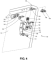
- FIG. 4 shows an exploded isometric view of the door assembly 132 of the passage door assembly 104 of FIG. 1 , according to at least one example.
- the emergency passage feature assembly 130 functions to connect the moveable door 112 to the carriage assembly 134.
- the door assembly 132 includes a first spigot block 140 and a second spigot block 142 configured to releasably receive corresponding latching spigots of the carriage assembly 134.
- the spigot blocks 140 and 142 are mounted to the underside 138 of the lip 136 of the moveable door 112. In some examples, only a single spigot block (e.g., the spigot block 142) may be provided. In some examples, more than two spigot blocks may be used.
- a bottom roller assembly 144 is also mounted to the underside 138 of the lip 136. Like the roller assembly 124, the bottom roller assembly 144 includes a roller 146 and functions to enable sliding movement of the moveable door 112 when the emergency passage door assembly 130 is in the emergency operating mode.
- the bottom roller assembly 144 is mounted in a recess 148 formed in the underside 138. In some examples, the bottom roller assembly 144 is surface mounted to the underside 138.
- the first spigot block 140 also includes an O-ring 150 and an O-ring retainer 152.
- the O-ring 150 is provided to prevent vibration when the first spigot block 140 receives a latching spigot into a spigot opening 154.
- the O-ring retainer 152 retains the O-ring 150.
- the O-ring 150 may also provide additional retaining forces for holding the latching spigot within the spigot opening 154 of the first spigot block 140.
- the spigot opening 154 may be shaped and sized to receive the latching spigot.
- the spigot opening 154 may have a cylindrical profile, square profile, or any other shape, and the latching spigot may have a corresponding shape.
- the second spigot block 142 similarly includes an O-ring 156, an O-ring retainer 158, and a spigot opening 160.
- the parts function similarly to those described above with respect to the first spigot block 140.
- the second spigot block 142 also includes catching opening 162 (not visible in FIG. 4 ) disposed in an axis that is about perpendicular with respect to an axis of the spigot opening 160.
- the catching opening 162 is configured to retain a catching mechanism 164.
- the catching mechanism 164 which functions as a door engagement latch, includes a threaded exterior surface corresponding to threads formed along an interior surface of the catching opening 162.
- the catching mechanism 164 includes a spring or other biasing member biased within an interior cavity and exerting a biasing force on a ball 166 disposed at a distal end of the catching mechanism 164.
- the catching mechanism 164 is mounted in the catching opening 162 (e.g., via the threads, using a press-fit, glue, or other suitable method) at least until the ball 166 intersects a portion of the spigot opening 160.
- the ball 166 is configured to engage with a groove on a latching spigot of the carriage assembly in order to couple the two assemblies together.
- an opening force exceeds some predefined threshold force (e.g., one that is a function of force present between the ball 166 and the groove of the latching spigot as a result of the biasing member)
- some predefined threshold force e.g., one that is a function of force present between the ball 166 and the groove of the latching spigot as a result of the biasing member
- the door assembly 132 also includes a roller bracket 168, a roller 170, and a roller support pin 172.
- the roller support pin 172 is held within the roller bracket 168 and retains and supports the roller 170.
- the roller bracket 168 is connected to the second spigot block 142. In some examples, the roller bracket 168 is connected to the underside 138.
- the moveable door 112 may include an indicator that mechanically or electronically indicates a state of the door. For example, once the door assembly 132 has been decoupled from the carriage assembly 134, one or more state indicators (e.g., on an inside or outside surface of the moveable door 112, adjacent the passenger seat 102, or at any other location) may be changed to indicate that the system is operating in the emergency operating mode. Once the door assembly 132 has again been coupled to the carriage assembly 134, the state indicator may revert back to represent that the system is operating in the normal operating mode.
- one or more state indicators e.g., on an inside or outside surface of the moveable door 112, adjacent the passenger seat 102, or at any other location
- FIG. 5 shows an exploded isometric view of the carriage assembly 134 of the passage door assembly 104 of FIG. 1 , according to at least one example.
- the carriage assembly 134 has been rotated about 180 degrees about the slide axis from the views illustrated in previous figures.
- the carriage assembly 134 includes a bracket 171 configured to retain a pair of carriage slide blocks 174a and 174b and corresponding spacers 176a and 176b.
- the carriage slide blocks 174 include one or more grooves corresponding to ridges of the slide track 118.
- the carriage assembly 134 also includes an aft spigot block 178.
- the aft spigot block 178 includes an aft spigot block opening 180 configured to receive a first end of an aft latching spigot 182.
- the aft latching spigot 182 includes a distal end 184 at an opposite end of the aft spigot 182.
- the aft latching spigot 182 includes a groove 186 adjacent to the distal end 184. The groove 186 is configured to engage with the ball 166 of the catching mechanism 164 within the opening 160 when in the normal operating mode.
- the carriage assembly 134 also includes a forward spigot block 188.
- the forward spigot block 188 includes a forward spigot block opening 190 configured to receive a first end of a forward latching spigot 192.
- the forward latching spigot 192 includes a distal end 194 at an opposite end of the forward latching spigot 192.
- the forward latching spigot 192, the distal end 194 in particular, is configured to be received by the spigot opening 154.
- the carriage assembly 134 also includes a spring 196 that is used to help release the carriage assembly 134 from the door assembly 132.
- the spigot blocks may include a retaining ring disposed along an interior surface of the spigot block and configured to frictionally and/or mechanically retain the latching spigot.
- This ring may dimensioned to have an opening that is smaller than an exterior dimension of the corresponding latching spigot (or a bulbous distal tip of the latching spigot).
- the latching spigot When an emergency force is exerted on the door, the latching spigot is released by the retaining ring because the force exerted by the retaining ring on the latching spigot is less than the emergency opening force. In this manner, the emergency force will cause the latching spigot to translate within the block and past the retaining ring.
- FIG. 6 shows an isometric view and a detail view of the emergency passage feature assembly 130 of the passage door assembly 104 of FIG. 1 in a normal operating mode, according to at least one example.
- the bracket 171 is omitted to illustrate the components behind the bracket 171.
- an opening force 198 that is within some predefined range (e.g., 3-4 lbs, approximately 1.4-1.8kg) is suitable for causing the moveable door 112 to slide with respect to the fixed wall 110 via the carriage slide blocks 174a and 174b.
- the range may include values smaller than 3lbs (approximately 1.4kg) and/or larger than 4lbs (approximately 1.8kg).
- the opening force 198 may be configurable depending on the application.
- the forward latching spigot 192 is disposed within spigot block 140 and the aft latching spigot 182 is disposed within the spigot block 142.
- the aft latching spigot 182 is held within the spigot block 142 by the ball 166 of the catching mechanism 164 being forcibly held within the groove 186 of the aft latching spigot 182.
- the roller 170 is spaced apart from the slide track 118 in a manner such that the roller 170 does not contact the slide track 118.
- neither of the rollers 126 or 146 is contacted to enable sliding of the moveable door 112. This is because the moveable door 112 is supported by the carriage assembly 134.
- the fixed wall 110 may also include a mounting bracket for retaining electrical wires (e.g., within a cat-track assembly), lighting elements, and the like.
- a cat-track assembly may be provided below the slide track 118, with a first end connected to the door assembly 132 and a second running within the mounting bracket and continuing to a power source.
- the fixed wall 110 may also include a shroud for covering the mounting bracket and those items retained by the mounting bracket.
- FIG. 7 shows an isometric view and a detail view of the emergency passage feature assembly 130 of the passage door assembly 104 of FIG. 1 in an emergency operating mode, according to at least one example.
- the bracket 171 is omitted to illustrate the components behind the bracket 171.
- an emergency opening force 199 that is within some second predefined range (e.g., 6-8 lbs, approximately 2.7-3.6kg) that is greater than the first predefined range is suitable for overcoming the force exerted by the catching mechanism 164 on the groove 186 of the latching spigot 182 by the ball 166.
- some second predefined range e.g., 6-8 lbs, approximately 2.7-3.6kg
- the catching mechanism 164 effectively releases the latching spigot 182, thereby decoupling the moveable door 112 from the carriage assembly 134 and allowing the moveable door 112 to slide without the carriage assembly 134.
- the second predefined range may include values smaller than 6lbs (approximately 2.7kg) and/or larger than 8lbs (approximately 3.6kg).
- the emergency opening force 199 may be configurable depending on the application.
- the entire moveable door 112 moves down toward the top edge surface 116 (e.g., by gravity towards the floor of the aircraft) at least until the roller 126 on the fixed wall 110 physically contacts the underside 138 of the lip 136 and the roller 146 physically contacts the top edge surface 116.
- the moveable door 112 may move only a short distance (e.g., between 50 and 100 thousandths of an inch (between approximately 1.27mm and 2.54mm), less than 50 thousandths of an inch (less than approximately 1.27mm), or greater than 100 thousandths of an inch (greater than approximately 2.54mm)).
- the roller bracket 168 keeps the moveable door 112 from moving laterally and the roller 170 keeps the moveable door 112 from rotating away from the fixed wall 110 when the moveable door 112 extends into a closed position (e.g., when the door is between 50% and 100% closed).
- deploying the moveable door 112 may include exerting a force on the moveable door 112 that is opposite in direction of and equal to or greater than in magnitude the emergency opening force 199. This "pushing" force causes the latching spigots 182 and 192 to enter the spigot blocks 140 and 142 such that at least one spigot block is held by the catching mechanism 164.
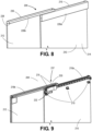
- FIG. 8 shows an isometric view of a passage door assembly 204 including an emergency passage feature assembly 230 for use with the passenger accommodation system 100 of FIG. 1 , according to at least one example.
- the passage door assembly 204 includes a fixed wall 210 and moveable door 212.
- the fixed wall 210 includes an inward-facing surface 214 and a top edge surface 216.
- the moveable door 212 includes a lip 236, which includes an underside 238.
- a cover or bezel 228a may be releasably mounted to the inward-facing surface 214 of the fixed wall 210 to cover a primary slide track 218a (see FIG. 9 ) and other assemblies described herein and mounted to the primary slide track 218a.
- a cover or bezel 228b may be releasably mounted to the lip 236 to cover a secondary slide track 218b (see FIG. 9 ) and other assembles described herein and mounted to the secondary slide track 218b.
- FIG. 9 shows an isometric view of the passage door assembly 204 of FIG. 8 illustrating internal components of the emergency passage feature assembly 230, according to at least one example.
- the emergency passage feature assembly 230 includes the primary slide track 218a, the secondary slide track 218b, a carriage assembly 232, and a door carriage assembly 237.
- the primary slide track 218a is configured like the slide track 118.
- the secondary slide track 218b is mounted on the underside 238 of the lip 236.
- the carriage assembly 232 is generally configured like the carriage assembly 134. However, rather than the coupling being between a door assembly and the carriage assembly, in the embodiment of FIG. 9 , the coupling occurs between the carriage assembly 232 and the door carriage assembly 237 includes a pair of carriage slide blocks 275.
- FIG. 10 shows an isometric view of the passage door assembly 204 of FIG. 8 in a normal operating mode, according to at least one example.
- the carriage assembly 232 is coupled to the door carriage assembly 237 via one or more latching spigots, corresponding spigot blocks, and catching mechanisms as described herein.
- both assemblies 232 and 237 move together, as the carriage assembly 232 moves along the primary slide track 218a, responsive to an opening force 298.
- the moveable door 212 slides between an open and closed position along the primary slide track 218a in a normal operating manner.
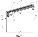
- FIG. 11 shows an isometric view of the passage door assembly 204 of FIG. 8 in an emergency operating mode, according to at least one example.
- the carriage assembly 232 is decoupled from the door carriage assembly 237, as one or more latching spigots connected to the carriage slide blocks are removed from corresponding spigot blocks and/or catching mechanisms as described herein.
- the assemblies 232 and 237 remain stationary, as the moveable door 212 slides in and out along the secondary slide track 218b, responsive to an emergency opening force 299.
- the moveable door 212 slides between an open and closed position along the secondary slide track 218b in an emergency operating manner.
- FIG. 12 shows a flow chart illustrating an example process 1200 of operating a moveable door including an emergency passage feature assembly, according to at least one example.
- the process 1200 may begin at 1202 by opening a moveable passenger door (e.g., 112) by applying an opening force (e.g., 198) in a first direction towards a fixed wall (e.g., 114) and along a slide axis (e.g., 120).
- the opening force may cause the moveable passenger door to translate with respect to the fixed wall via a carriage assembly (e.g., 134) that is removably coupled to the moveable passenger door via a door assembly (e.g., 132) and slidably connected to a slide track (e.g., 118) of the fixed wall.
- the process 1200 includes opening the moveable passenger door by applying an emergency force (e.g., 199) in the first direction towards the fixed wall and along the slide axis.
- the emergency force may cause the door assembly to decouple from the carriage assembly, and the moveable passenger door to translate with respect to the fixed wall via the door assembly independent of the carriage assembly.
- the emergency force may cause the moveable passenger door to translate in a second direction at least until a portion of the door assembly physically contacts a top portion (e.g., 116) of the fixed wall.
- the second direction may be substantially perpendicular to the first direction.
- the portion of the door assembly is spaced apart (e.g., some non-zero distance such as less than 0.125 inches (less than approximately 3.2mm)) from the top portion of the fixed wall prior to application of the emergency force.
- the process 1200 includes, after opening the moveable passenger door by applying the emergency force, deploying the moveable passenger door by applying a deployment force in a second direction opposite the first direction.
- the deployment force may cause the door assembly and the carriage assembly to couple together and return the moveable passenger door to the pre-emergency state.
- the emergency force is greater than the opening force.
- the deployment force is greater than or equal to the emergency force.
- Disjunctive language such as the phrase "at least one of X, Y, or Z," unless specifically stated otherwise, is otherwise understood within the context as used in general to present that an item, term, etc. may be either X, Y, or Z, or any combination thereof (e.g., X, Y, and/or Z). Thus, such disjunctive language is not generally intended to, and should not, imply that certain examples require at least one of X, at least one of Y, or at least one of Z to each be present.
- a or B or C includes any or all of the following alternative combinations as appropriate for a particular usage: A alone; B alone; C alone; A and B only; A and C only; B and C only; and all three of A and B and C.
Landscapes
- Engineering & Computer Science (AREA)
- Aviation & Aerospace Engineering (AREA)
- Mechanical Engineering (AREA)
- Support Devices For Sliding Doors (AREA)
- Wing Frames And Configurations (AREA)
- Lock And Its Accessories (AREA)
- Business, Economics & Management (AREA)
- Emergency Management (AREA)
- Power-Operated Mechanisms For Wings (AREA)
Description
- This application claims the benefit of
U.S. Provisional Application No. 62/927,411, filed on October 29, 2019 - The field of the disclosure relates to passage doors within passenger aircrafts. In particular, passage doors for passenger suites including emergency passage features are described.
- Some passenger aircraft include mini-suites, which, especially on aircraft designed for long hauls, define semi-private spaces for passengers. For example, these mini-suites may each include a passenger seat, a small table, and a seat shell having short walls surrounding the space. Each mini-suite may have its own door for accessing the mini-suite. To comply with government regulations, each door may also be outfitted with an emergency passage feature (EPF). The EPF provides an alternate means for opening the door in the event that the door becomes jammed. Conventional doors including EPF systems may be overly mechanically complex, may be prone to jamming (even when the EPF is deployed), and/or may open into passenger aisles, thereby obstructing passenger movement.
WO2018/093825A1 andCA3047149A1 disclose emergency passage features for aircraft passenger suites.KR200444723Y1 JP5084035B2 - Examples of the disclosed embodiments covered by this patent are defined by the claims below, not this summary. This summary is a high-level overview of various aspects of the disclosure and introduces some of the concepts that are further described in the Detailed Description section below. This summary is not intended to identify key or essential features of the claimed subject matter, nor is it intended to be used in isolation to determine the scope of the claimed subject matter. The subject matter should be understood by reference to appropriate portions of the entire specification of this patent, any or all drawings, and each claim.
- A general aspect includes a passenger accommodation system, including a fixed wall forming a fixed part of a seating compartment; a moveable door forming a moveable part of the seating compartment; a slide track mounted to the fixed wall and defining a slide axis; a carriage assembly slidably mountable to the slide track via one or more slide carriages to enable slidable movement of the carriage assembly along the slide axis, the carriage assembly including a latching spigot aligned with the slide axis; and a door assembly configured to mount to the moveable door and mate with the carriage assembly to enable slidable movement of the moveable door with respect to the fixed wall. The door assembly includes a latching block aligned with the slide axis and configured to selectively receive the latching spigot by at least: (1) responsive to a first opening force applied at the moveable door, retaining the latching spigot to enable the moveable door, the carriage assembly, and the door assembly to slide along the slide track; and (2) responsive to a second opening force applied at the moveable door, the door assembly also includes releasing the latching block to enable the latching block and the moveable door to slide with respect to the fixed wall independent of the carriage assembly.
- Another general aspect includes a method of operating a moveable passenger door, including: opening the moveable passenger door by applying an opening force in a first direction towards a fixed wall and along a slide axis. The opening force causes the moveable passenger door to translate with respect to the fixed wall via a carriage assembly that is removably coupled to the moveable passenger door via a door assembly and slidably connected to a slide track of the fixed wall. The method also includes opening the moveable passenger door by applying an emergency force in the first direction towards the fixed wall and along the slide axis. The emergency force causes the door assembly to decouple from the carriage assembly, and the moveable passenger door to translate with respect to the fixed wall via the door assembly independent of the carriage assembly.
-
-
FIG. 1 shows an isometric view of a passenger accommodation system including a passenger seat and a passage door assembly, according to at least one example. -
FIG. 2 shows an isometric view of a fixed wall of the passenger accommodation system ofFIG. 1 , according to at least one example. -
FIG. 3 shows a detailed isometric view of an emergency passage feature assembly of the passage door assembly ofFIG. 1 , according to at least one example. -
FIG. 4 shows an exploded isometric view of a door assembly of the passage door assembly ofFIG. 1 , according to at least one example. -
FIG. 5 shows an exploded isometric view of a carriage assembly of the passage door assembly ofFIG. 1 , according to at least one example. -
FIG. 6 shows an isometric view and a detail view of the emergency passage feature assembly of the passage door assembly ofFIG. 1 in a normal operating mode, according to at least one example. -
FIG. 7 shows an isometric view and a detail view of the emergency passage feature assembly of the passage door assembly ofFIG. 1 in an emergency operating mode, according to at least one example. -
FIG. 8 shows an isometric view of a passage door assembly including an emergency passage feature assembly for use with the passenger accommodation system ofFIG. 1 , according to at least one example. -
FIG. 9 shows an isometric view of the passage door assembly ofFIG. 8 illustrating internal components of the emergency passage feature assembly, according to at least one example. -
FIG. 10 shows an isometric view of the passage door assembly ofFIG. 8 in a normal operating mode, according to at least one example. -
FIG. 11 shows an isometric view and a detail view of the passage door assembly ofFIG. 8 in an emergency operating mode, according to at least one example. -
FIG. 12 shows a flow chart illustrating an example process of operating a moveable door including an emergency passage feature assembly, according to at least one example. - The subject matter of examples of the present disclosure is described here with specificity to meet statutory requirements, but this description is not necessarily intended to limit the scope of the claims.
- This description should not be interpreted as implying any particular order or arrangement among or between various steps or elements except when the order of individual steps or arrangement of elements is explicitly described.
- The described examples of the disclosure provide various passage door assemblies including emergency passage features for use on passenger accommodation systems of passenger aircraft and/or in other passenger locations where privacy or semi-privacy may be desired. Unlike conventional passage assemblies including emergency passage features, those described herein include a single moveable door that is opened in the normal mode and the emergency mode using the same action. In particular, to open the moveable door in the normal operating mode, a passenger simply exerts a first opening force (e.g., 3-4 lbs, approximately 1.4-1.8kg) on the moveable door in an opening direction. To open the door in the emergency mode (e.g., if the main opening structure gets jammed), the passenger exerts a second slightly greater opening force (e.g., 6-8 lbs, approximately 2.7-3.6kg) at the same location on the moveable door and in the same direction. In some examples, the greater opening force is 3 to 4 times greater than the first opening force. Resetting the moveable door (e.g., after emergency operation) is also simplified in comparison to conventional passage door assemblies that include various mechanical levers and/or hinged parts. To do so, a force that is about equal in magnitude to the second opening force is exerted at the moveable door but in a direction opposite the opening forces. Additionally, because the door slides forward and aft in one plane, there is little to no possibility that the door will obstruct the passenger seating area or an adjacent passenger aisle as do conventional doors that swing.
- In a particular example, a passenger accommodation system such as a mini-suite includes a passenger seat located within a semi-private area defined by a seat shell including at least one fixed wall and a moveable door. The fixed wall and the moveable door may be oriented in a coplanar orientation and slidably coupled such that the moveable door slides with respect to the fixed wall. To enable the slidable coupling, a slide track, a carriage assembly, and a door assembly are provided. The slide track is connected to the fixed wall and defines a slide axis of the moveable door extending generally forward and aft with respect to the passenger seat. The carriage assembly is slidably mounted to the slide track via one or more slide carriages. The carriage assembly also includes a latching spigot that is generally aligned with the slide axis. The door assembly is mounted to the moveable door and includes a latching block to selectively retain the latching spigot of the carriage assembly. In a normal operating mode, the latching spigot is held by the latching block such that the carriage assembly and the moveable door together slide along the slide track. In an emergency operating mode, the latching spigot is removed from the latching block (e.g., by an emergency opening force), thereby freeing the moveable door from the carriage assembly and enabling the moveable door to slide freely along a top edge of the fixed wall, i.e., disconnected from the slide track but along the same slide axis (e.g., generally forward and aft). In some examples, rollers are provided at the top edge of the fixed wall and on an underside of the moveable door to improve sliding of the moveable door in the emergency operating mode.
- Turning now to the figures,
FIG. 1 shows an isometric view of apassenger accommodation system 100 including apassenger seat 102 and apassage door assembly 104, according to at least one example. Multiple ones of thepassenger accommodation system 100 may be disposed within an aircraft or other vehicle to provide semi-private or entirely private spaces for passenger occupation during travel. In some examples, an entire passenger seating area of the aircraft is devoted topassenger accommodation systems 100 of the same type. In other examples, different classes of seating areas may be provided in the aircraft, including certain areas that include similarpassenger accommodation systems 100, traditional dense row and column seating, and other seating arrangements. In some examples, multiplepassenger accommodation systems 100 are laid out in a grid pattern within a seating area, with thepassenger seats 102 oriented generally forward in the aircraft, andpassenger accommodation systems 100 running forward to aft in columns and being separated by longitudinal aisles. Thus, a single aisle may serve multiple passengers occupying multiplepassenger accommodation systems 100. - The
passenger accommodation system 100 also includes aseat shell 106 that extends around thepassenger seat 102 and provides privacy walls for a passenger occupying thepassenger seat 102. Thepassenger accommodation system 100 also includes a table 108, which may include a top for holding food trays, beverages, reading materials, etc. and a hollow space for stowage of passenger items and/or other items provided for the passenger. In some examples, theseat shell 106 may extend from a floor to a ceiling of the aircraft or may only extend partway. Theseat shell 106 may be configured to couple with and/or include a part of thepassage door assembly 104. For example, thepassage door assembly 104 may include afixed wall 110 and amoveable door 112, and the fixedwall 110 may be integrally formed with theseat shell 106 or may otherwise be configured to couple with theseat shell 106. -
FIG. 2 shows an isometric view of the fixedwall 110 of thepassenger accommodation system 100 ofFIG. 1 , according to at least one example. The fixedwall 110, themoveable door 112, and any other portion of thepassenger accommodation system 100 may be formed from any suitable material such as plastic, aluminum, glass, dense foam, wood, and the like. The fixedwall 110 includes an inward-facingsurface 114 and atop edge surface 116. Aslide track 118 is connected to the fixedwall 110 at the inward-facingsurface 114. Theslide track 118 extends along a longitudinal length of the fixedwall 110. Theslide track 118 defines aslide axis 120, which defines how themoveable door 112 moves with respect to the fixedwall 110. Theslide track 118 may be any suitable track, including channels, grooves, or the like configured to receive one or more sliding carriages to enable sliding movement, as described in detail with respect toFIG. 5 . - At the
top edge surface 116 of the fixedwall 110 is defined arecess 122, which is configured to receive aroller assembly 124. Theroller assembly 124 includes aroller 126 that, as described with respect to later figures, is used to support themoveable door 112 when themoveable door 112 is operated in the emergency operating mode. Theroller assembly 124 includes a tab for securing theroller assembly 124 in therecess 122. In some examples, a highest part of theroller 126, when theroller assembly 124 is mounted in therecess 122, may be slightly higher than thetop edge surface 116. For example, the difference between the highest part of theroller 126 and thetop edge surface 116 may be between 50 and 100 thousandths of an inch (between approximately 1.27mm and 2.54mm), less than 50 thousandths of an inch (less than approximately 1.27mm), or greater than 100 thousandths of an inch (greater than approximately 2.54mm). - As illustrated in
FIG. 2 , a cover orbezel 128 may be releasably mounted to the inward-facingsurface 114 of the fixedwall 110 to cover theslide track 118 and other assemblies described herein and mounted to theslide track 118. -
FIG. 3 shows a detailed isometric view of an emergencypassage feature assembly 130 of thepassage door assembly 104 ofFIG. 1 , according to at least one example. Thepassage door assembly 104 includes the fixedwall 110, theslide track 118, themoveable door 112, and the emergencypassage feature assembly 130. The emergencypassage feature assembly 130 includes adoor assembly 132 described with respect toFIG. 4 and acarriage assembly 134 described with respect toFIG. 5 . - The
moveable door 112 includes alip 136. When themoveable door 112 is coupled to the fixed wall, thelip 136 extends over and covers a portion of thetop edge surface 116 of the fixedwall 110. Thedoor assembly 132 is mounted to anunderside 138 of thelip 136, as shown inFIG. 4 . Thecarriage assembly 134 is a separate assembly that is slidably mounted to theslide track 118. As shown inFIGS. 6 and7 , thecarriage assembly 134 may be releasably connected to thedoor assembly 132. When the twoassemblies passage door assembly 104 is in the normal operating mode. When the twoassemblies passage door assembly 104 is in the emergency operating mode. -
FIG. 4 shows an exploded isometric view of thedoor assembly 132 of thepassage door assembly 104 ofFIG. 1 , according to at least one example. Generally, the emergencypassage feature assembly 130 functions to connect themoveable door 112 to thecarriage assembly 134. Thedoor assembly 132 includes afirst spigot block 140 and asecond spigot block 142 configured to releasably receive corresponding latching spigots of thecarriage assembly 134. The spigot blocks 140 and 142 are mounted to theunderside 138 of thelip 136 of themoveable door 112. In some examples, only a single spigot block (e.g., the spigot block 142) may be provided. In some examples, more than two spigot blocks may be used. - A
bottom roller assembly 144 is also mounted to theunderside 138 of thelip 136. Like theroller assembly 124, thebottom roller assembly 144 includes aroller 146 and functions to enable sliding movement of themoveable door 112 when the emergencypassage door assembly 130 is in the emergency operating mode. Thebottom roller assembly 144 is mounted in arecess 148 formed in theunderside 138. In some examples, thebottom roller assembly 144 is surface mounted to theunderside 138. - The
first spigot block 140 also includes an O-ring 150 and an O-ring retainer 152. The O-ring 150 is provided to prevent vibration when thefirst spigot block 140 receives a latching spigot into aspigot opening 154. The O-ring retainer 152 retains the O-ring 150. The O-ring 150 may also provide additional retaining forces for holding the latching spigot within thespigot opening 154 of thefirst spigot block 140. Thespigot opening 154 may be shaped and sized to receive the latching spigot. For example, thespigot opening 154 may have a cylindrical profile, square profile, or any other shape, and the latching spigot may have a corresponding shape. - Like the
first spigot block 140, thesecond spigot block 142 similarly includes an O-ring 156, an O-ring retainer 158, and aspigot opening 160. The parts function similarly to those described above with respect to thefirst spigot block 140. Thesecond spigot block 142, sometimes referred to as a latching block, also includes catching opening 162 (not visible inFIG. 4 ) disposed in an axis that is about perpendicular with respect to an axis of thespigot opening 160. The catchingopening 162 is configured to retain acatching mechanism 164. The catchingmechanism 164, which functions as a door engagement latch, includes a threaded exterior surface corresponding to threads formed along an interior surface of the catchingopening 162. The catchingmechanism 164 includes a spring or other biasing member biased within an interior cavity and exerting a biasing force on aball 166 disposed at a distal end of the catchingmechanism 164. To assemble, the catchingmechanism 164 is mounted in the catching opening 162 (e.g., via the threads, using a press-fit, glue, or other suitable method) at least until theball 166 intersects a portion of thespigot opening 160. In operation, theball 166 is configured to engage with a groove on a latching spigot of the carriage assembly in order to couple the two assemblies together. When an opening force exceeds some predefined threshold force (e.g., one that is a function of force present between theball 166 and the groove of the latching spigot as a result of the biasing member), theball 166 is removed from the groove and the latching spigot is free to be removed from thespigot opening 160. - The
door assembly 132 also includes aroller bracket 168, aroller 170, and aroller support pin 172. Theroller support pin 172 is held within theroller bracket 168 and retains and supports theroller 170. Theroller bracket 168 is connected to thesecond spigot block 142. In some examples, theroller bracket 168 is connected to theunderside 138. When the emergencypassage feature assembly 130 is in the emergency operating mode, theroller 170 engages with the bottom side of theslide track 118 and retains themoveable door 112 by keeping themoveable door 112 from tipping off ofslide track 118. - In some examples, the
moveable door 112 may include an indicator that mechanically or electronically indicates a state of the door. For example, once thedoor assembly 132 has been decoupled from thecarriage assembly 134, one or more state indicators (e.g., on an inside or outside surface of themoveable door 112, adjacent thepassenger seat 102, or at any other location) may be changed to indicate that the system is operating in the emergency operating mode. Once thedoor assembly 132 has again been coupled to thecarriage assembly 134, the state indicator may revert back to represent that the system is operating in the normal operating mode. -
FIG. 5 shows an exploded isometric view of thecarriage assembly 134 of thepassage door assembly 104 ofFIG. 1 , according to at least one example. For purposes of illustration, thecarriage assembly 134 has been rotated about 180 degrees about the slide axis from the views illustrated in previous figures. Thecarriage assembly 134 includes abracket 171 configured to retain a pair ofcarriage slide blocks corresponding spacers slide track 118. - The
carriage assembly 134 also includes anaft spigot block 178. Theaft spigot block 178 includes an aft spigot block opening 180 configured to receive a first end of anaft latching spigot 182. Theaft latching spigot 182 includes adistal end 184 at an opposite end of theaft spigot 182. Theaft latching spigot 182 includes agroove 186 adjacent to thedistal end 184. Thegroove 186 is configured to engage with theball 166 of the catchingmechanism 164 within theopening 160 when in the normal operating mode. - The
carriage assembly 134 also includes aforward spigot block 188. The forward spigot block 188 includes a forward spigot block opening 190 configured to receive a first end of aforward latching spigot 192. Theforward latching spigot 192 includes adistal end 194 at an opposite end of theforward latching spigot 192. Theforward latching spigot 192, thedistal end 194 in particular, is configured to be received by thespigot opening 154. Thecarriage assembly 134 also includes aspring 196 that is used to help release thecarriage assembly 134 from thedoor assembly 132. - Any suitable catching mechanism may be used to retain the latching spigot(s) in the latching blocks. For example, rather than a ball and spigot as described herein, the spigot blocks may include a retaining ring disposed along an interior surface of the spigot block and configured to frictionally and/or mechanically retain the latching spigot. This ring may dimensioned to have an opening that is smaller than an exterior dimension of the corresponding latching spigot (or a bulbous distal tip of the latching spigot). When a first opening force is exerted on the door, the latching spigot is retained by the retaining ring because the force exerted by the retaining ring on the latching spigot is greater than first opening force. When an emergency force is exerted on the door, the latching spigot is released by the retaining ring because the force exerted by the retaining ring on the latching spigot is less than the emergency opening force. In this manner, the emergency force will cause the latching spigot to translate within the block and past the retaining ring.
-
FIG. 6 shows an isometric view and a detail view of the emergencypassage feature assembly 130 of thepassage door assembly 104 ofFIG. 1 in a normal operating mode, according to at least one example. In the view illustrated inFIG. 6 , thebracket 171 is omitted to illustrate the components behind thebracket 171. In the normal operating mode, an openingforce 198 that is within some predefined range (e.g., 3-4 lbs, approximately 1.4-1.8kg) is suitable for causing themoveable door 112 to slide with respect to the fixedwall 110 via thecarriage slide blocks force 198 may be configurable depending on the application. - In the normal operating mode, the
forward latching spigot 192 is disposed withinspigot block 140 and theaft latching spigot 182 is disposed within thespigot block 142. In particular, theaft latching spigot 182 is held within thespigot block 142 by theball 166 of the catchingmechanism 164 being forcibly held within thegroove 186 of theaft latching spigot 182. In the normal operating mode, theroller 170 is spaced apart from theslide track 118 in a manner such that theroller 170 does not contact theslide track 118. Similarly, in the normal operating mode, neither of therollers moveable door 112. This is because themoveable door 112 is supported by thecarriage assembly 134. - The fixed
wall 110 may also include a mounting bracket for retaining electrical wires (e.g., within a cat-track assembly), lighting elements, and the like. For example, a cat-track assembly may be provided below theslide track 118, with a first end connected to thedoor assembly 132 and a second running within the mounting bracket and continuing to a power source. In some examples, the fixedwall 110 may also include a shroud for covering the mounting bracket and those items retained by the mounting bracket. -
FIG. 7 shows an isometric view and a detail view of the emergencypassage feature assembly 130 of thepassage door assembly 104 ofFIG. 1 in an emergency operating mode, according to at least one example. In the view illustrated inFIG. 7 , thebracket 171 is omitted to illustrate the components behind thebracket 171. In the emergency operating mode, anemergency opening force 199 that is within some second predefined range (e.g., 6-8 lbs, approximately 2.7-3.6kg) that is greater than the first predefined range is suitable for overcoming the force exerted by the catchingmechanism 164 on thegroove 186 of the latchingspigot 182 by theball 166. When this occurs, the catchingmechanism 164 effectively releases thelatching spigot 182, thereby decoupling themoveable door 112 from thecarriage assembly 134 and allowing themoveable door 112 to slide without thecarriage assembly 134. In some examples, the second predefined range may include values smaller than 6lbs (approximately 2.7kg) and/or larger than 8lbs (approximately 3.6kg). In any event, theemergency opening force 199 may be configurable depending on the application. - In operation, as the latching
spigots moveable door 112 moves down toward the top edge surface 116 (e.g., by gravity towards the floor of the aircraft) at least until theroller 126 on the fixedwall 110 physically contacts theunderside 138 of thelip 136 and theroller 146 physically contacts thetop edge surface 116. In some examples, themoveable door 112 may move only a short distance (e.g., between 50 and 100 thousandths of an inch (between approximately 1.27mm and 2.54mm), less than 50 thousandths of an inch (less than approximately 1.27mm), or greater than 100 thousandths of an inch (greater than approximately 2.54mm)). In the emergency operating mode, theroller bracket 168 keeps themoveable door 112 from moving laterally and theroller 170 keeps themoveable door 112 from rotating away from the fixedwall 110 when themoveable door 112 extends into a closed position (e.g., when the door is between 50% and 100% closed). - In some examples, deploying the moveable door 112 (e.g., restoring the
passage door assembly 104 to the normal operating mode) may include exerting a force on themoveable door 112 that is opposite in direction of and equal to or greater than in magnitude theemergency opening force 199. This "pushing" force causes the latchingspigots mechanism 164. -
FIG. 8 shows an isometric view of apassage door assembly 204 including an emergencypassage feature assembly 230 for use with thepassenger accommodation system 100 ofFIG. 1 , according to at least one example. Thepassage door assembly 204 includes a fixedwall 210 andmoveable door 212. The fixedwall 210 includes an inward-facingsurface 214 and atop edge surface 216. Themoveable door 212 includes alip 236, which includes anunderside 238. As illustrated inFIG. 8 , a cover orbezel 228a may be releasably mounted to the inward-facingsurface 214 of the fixedwall 210 to cover aprimary slide track 218a (seeFIG. 9 ) and other assemblies described herein and mounted to theprimary slide track 218a. A cover orbezel 228b may be releasably mounted to thelip 236 to cover asecondary slide track 218b (seeFIG. 9 ) and other assembles described herein and mounted to thesecondary slide track 218b. -
FIG. 9 shows an isometric view of thepassage door assembly 204 ofFIG. 8 illustrating internal components of the emergencypassage feature assembly 230, according to at least one example. InFIG. 9 , theshroud 228a has been removed, revealingshroud brackets 215, andshroud 228b has been made transparent to view internal components. The emergencypassage feature assembly 230 includes theprimary slide track 218a, thesecondary slide track 218b, acarriage assembly 232, and adoor carriage assembly 237. Theprimary slide track 218a is configured like theslide track 118. Thesecondary slide track 218b is mounted on theunderside 238 of thelip 236. Thecarriage assembly 232 is generally configured like thecarriage assembly 134. However, rather than the coupling being between a door assembly and the carriage assembly, in the embodiment ofFIG. 9 , the coupling occurs between thecarriage assembly 232 and thedoor carriage assembly 237 includes a pair of carriage slide blocks 275. -
FIG. 10 shows an isometric view of thepassage door assembly 204 ofFIG. 8 in a normal operating mode, according to at least one example. In a normal operating mode, thecarriage assembly 232 is coupled to thedoor carriage assembly 237 via one or more latching spigots, corresponding spigot blocks, and catching mechanisms as described herein. In this manner, bothassemblies carriage assembly 232 moves along theprimary slide track 218a, responsive to anopening force 298. In particular, themoveable door 212 slides between an open and closed position along theprimary slide track 218a in a normal operating manner. -
FIG. 11 shows an isometric view of thepassage door assembly 204 ofFIG. 8 in an emergency operating mode, according to at least one example. In the emergency operating mode, thecarriage assembly 232 is decoupled from thedoor carriage assembly 237, as one or more latching spigots connected to the carriage slide blocks are removed from corresponding spigot blocks and/or catching mechanisms as described herein. In this manner, theassemblies moveable door 212 slides in and out along thesecondary slide track 218b, responsive to anemergency opening force 299. In particular, themoveable door 212 slides between an open and closed position along thesecondary slide track 218b in an emergency operating manner. -
FIG. 12 shows a flow chart illustrating anexample process 1200 of operating a moveable door including an emergency passage feature assembly, according to at least one example. Theprocess 1200 may begin at 1202 by opening a moveable passenger door (e.g., 112) by applying an opening force (e.g., 198) in a first direction towards a fixed wall (e.g., 114) and along a slide axis (e.g., 120). The opening force may cause the moveable passenger door to translate with respect to the fixed wall via a carriage assembly (e.g., 134) that is removably coupled to the moveable passenger door via a door assembly (e.g., 132) and slidably connected to a slide track (e.g., 118) of the fixed wall. - At 1204, the
process 1200 includes opening the moveable passenger door by applying an emergency force (e.g., 199) in the first direction towards the fixed wall and along the slide axis. The emergency force may cause the door assembly to decouple from the carriage assembly, and the moveable passenger door to translate with respect to the fixed wall via the door assembly independent of the carriage assembly. In some examples, the emergency force may cause the moveable passenger door to translate in a second direction at least until a portion of the door assembly physically contacts a top portion (e.g., 116) of the fixed wall. In some examples, the second direction may be substantially perpendicular to the first direction. In some examples, the portion of the door assembly is spaced apart (e.g., some non-zero distance such as less than 0.125 inches (less than approximately 3.2mm)) from the top portion of the fixed wall prior to application of the emergency force. - At 1206, the
process 1200 includes, after opening the moveable passenger door by applying the emergency force, deploying the moveable passenger door by applying a deployment force in a second direction opposite the first direction. The deployment force may cause the door assembly and the carriage assembly to couple together and return the moveable passenger door to the pre-emergency state. In some examples, the emergency force is greater than the opening force. In some examples, the deployment force is greater than or equal to the emergency force. - Different arrangements of the components depicted in the drawings or described above, as well as components and steps not shown or described, are possible. Similarly, some features and sub-combinations are useful and may be employed without reference to other features and sub-combinations. Examples of the invention have been described for illustrative and not restrictive purposes, and alternative examples will become apparent to readers of this patent. Accordingly, the present invention is not limited to the examples described above or depicted in the drawings, and various examples and modifications may be made without departing from the scope of the claims below.
- The terms "invention," "the invention," "this invention," and "the present invention" used in this patent are intended to refer broadly to all of the subject matter of this patent and the patent claims below. Statements containing these terms should be understood not to limit the subject matter described herein or to limit the meaning or scope of the patent claims below.
- Other variations are within the spirit of the present disclosure. Thus, while the disclosed techniques are susceptible to various modifications and alternative constructions, certain illustrated examples thereof are shown in the drawings and have been described above in detail.
- The use of the terms "a," "an," and "the" and similar referents in the context of describing the disclosed examples (especially in the context of the following claims) are to be construed to cover both the singular and the plural, unless otherwise indicated herein or clearly contradicted by context. The terms "comprising," "having," "including," and "containing" are to be construed as open-ended terms (e.g., meaning "including, but not limited to,"), unless otherwise noted. The term "connected" is to be construed as partly or wholly contained within, attached to, or joined together, even if there is something intervening. Recitation of ranges of values herein are merely intended to serve as a shorthand method of referring individually to each separate value falling within the range, unless otherwise indicated herein, and each separate value is incorporated into the specification as if it were individually recited herein. All methods described herein can be performed in any suitable order, unless otherwise indicated herein or otherwise clearly contradicted by context. The use of any and all examples, or exemplary language (e.g., "such as") provided herein, is intended merely to better illuminate examples of the disclosure and does not pose a limitation on the scope of the disclosure unless otherwise claimed. No language in the specification should be construed as indicating any non-claimed element as essential to the practice of the disclosure.
- Disjunctive language such as the phrase "at least one of X, Y, or Z," unless specifically stated otherwise, is otherwise understood within the context as used in general to present that an item, term, etc. may be either X, Y, or Z, or any combination thereof (e.g., X, Y, and/or Z). Thus, such disjunctive language is not generally intended to, and should not, imply that certain examples require at least one of X, at least one of Y, or at least one of Z to each be present.
- Use herein of the word "or" is intended to cover inclusive and exclusive OR conditions. In other words, A or B or C includes any or all of the following alternative combinations as appropriate for a particular usage: A alone; B alone; C alone; A and B only; A and C only; B and C only; and all three of A and B and C.
- Preferred examples of this disclosure are described herein, including the best mode known to the inventors for carrying out the disclosure. Variations of those preferred examples may become apparent to those of ordinary skill in the art upon reading the foregoing description. The inventors expect skilled artisans to employ such variations as appropriate, and the inventors intend for the disclosure to be practiced otherwise than as specifically described herein.
Claims (12)
- A passenger accommodation system (100), comprising:a fixed wall (110, 210) forming a fixed part of a seating compartment;a moveable door (112, 212) forming a moveable part of the seating compartment;a slide track (118) mounted to the fixed wall (110, 210) and defining a slide axis (120);a carriage assembly (134, 232) slidably mountable to the slide track (118) via one or more slide carriages to enable slidable movement of the carriage assembly (134, 232) along the slide axis (120), the carriage assembly (134, 232) comprising a latching spigot (182, 192); anda door assembly (132) configured to mount to the moveable door (112, 212) and mate with the carriage assembly (134, 232) to enable slidable movement of the moveable door (112, 212) with respect to the fixed wall (110, 210), the door assembly (132) comprising a latching block aligned with the slide axis (120);characterized in that the latching spigot of the carriage assembly is aligned with the slide axis (120);wherein the latching block of the door assembly is configured to selectively receive the latching spigot (182, 192) by at least:responsive to a first opening (160, 162) force applied at the moveable door (112, 212), retaining the latching spigot (182, 192) to enable the moveable door (112, 212), the carriage assembly (134, 232), and the door assembly (132) to slide along the slide track (118); andresponsive to a second opening (160, 162) force applied at the moveable door (112, 212), releasing the latching block to enable the latching block and the moveable door (112, 212) to slide with respect to the fixed wall (110, 210) independent of the carriage assembly (134, 232).
- The passenger accommodation system (100) of claim 1, wherein the second opening (160, 162) force is greater than the first opening (160, 162) force.
- The passenger accommodation system (100) of claim 1, wherein the carriage assembly (134, 232) further comprises an alignment spigot aligned with the slide axis (120), and wherein the door assembly (132) further comprises an alignment block aligned with the slide axis (120) and configured to selectively receive the alignment spigot.
- The passenger accommodation system (100) of claim 1, wherein the moveable door (112, 212) comprises a lip (136, 236) extending in the direction of the slide axis (120) and to which is mounted a door roller (126, 146, 170) assembly comprising one or more rollers (126, 146).
- The passenger accommodation system (100) of claim 4, wherein the moveable door (112, 212) sliding with respect to the fixed wall (110, 210) independent of the carriage assembly (134, 232) comprises the one or more rollers (126, 146) of the door roller (126, 146, 170) assembly in physically contacting a top surface of the fixed wall (110, 210), enabling slidable movement of the moveable door (112, 212) with respect to the fixed wall (110, 210), and supporting the weight of the moveable door (112, 212).
- The passenger accommodation system (100) of claim 1, wherein the latching block further comprises a catching mechanism (164) disposed within the latching block and configured to translate between a first position in which the catching mechanism (164) retains the latching spigot (182, 192) responsive to the first opening (160, 162) force and a second position in which the catching mechanism (164) releases the latching spigot (182, 192) responsive to the second opening (160, 162) force.
- The passenger accommodation system (100) of claim 6, wherein the catching mechanism (164) comprises a biasing member biased to cause translation of a distal end (184, 194) of the catching mechanism (164) with respect to the latching spigot (182, 192) in a direction that is substantially perpendicular to the slide axis (120) between the first position and the second position.
- The passenger accommodation system (100) of claim 1, further comprising a passenger seat (102) connected to the fixed wall (110, 210), the moveable passenger door enabling passenger egress to and from the passenger seat (102) responsive to the first opening (160, 162) force and the second opening (160, 162) force.
- A method of operating a moveable passenger door, comprising:opening the moveable passenger door by applying an opening (160, 162) force in a first direction towards a fixed wall (110, 210) and along a slide axis (120), the opening (160, 162) force causing the moveable passenger door to translate with respect to the fixed wall (110, 210) via a carriage assembly (134, 232) that is removably coupled to the moveable passenger door via a door assembly (132) and slidably connected to a slide track (118) of the fixed wall (110, 210);characterized in that the method further comprises:
opening the moveable passenger door by applying an emergency force in the first direction towards the fixed wall (110, 210) and along the slide axis (120), the emergency force causing:the door assembly (132) to decouple from the carriage assembly (134, 232); andthe moveable passenger door to translate with respect to the fixed wall (110, 210) via the door assembly (132) independent of the carriage assembly (134, 232). - The method of claim 9, further comprising, after opening the moveable passenger door by applying the emergency force, deploying the moveable passenger door by applying a deployment force in a second direction opposite the first direction, the deployment force causing the door assembly (132) and the carriage assembly (134, 232) to couple together.
- The method of claim 9, wherein the emergency force is greater than the opening (160, 162) force.
- The method of claim 9, wherein the emergency force further causes the moveable passenger door to translate in a second direction at least until a portion of the door assembly (132) physically contacts a top portion of the fixed wall (110, 210), wherein the second direction is substantially perpendicular to the first direction, and wherein the portion of the door assembly (132) is spaced apart from the top portion of the fixed wall (110, 210) prior to application of the emergency force.
Applications Claiming Priority (2)
| Application Number | Priority Date | Filing Date | Title |
|---|---|---|---|
| US201962927411P | 2019-10-29 | 2019-10-29 | |
| PCT/IB2020/060176 WO2021084479A1 (en) | 2019-10-29 | 2020-10-29 | Emergency passage door |
Publications (2)
| Publication Number | Publication Date |
|---|---|
| EP4051588A1 EP4051588A1 (en) | 2022-09-07 |
| EP4051588B1 true EP4051588B1 (en) | 2024-05-15 |
Family
ID=73131778
Family Applications (2)
| Application Number | Title | Priority Date | Filing Date |
|---|---|---|---|
| EP20816582.9A Active EP4051588B1 (en) | 2019-10-29 | 2020-10-29 | Emergency passage door |
| EP20801366.4A Active EP4051587B1 (en) | 2019-10-29 | 2020-10-29 | An aircraft passenger accommodation unit |
Family Applications After (1)
| Application Number | Title | Priority Date | Filing Date |
|---|---|---|---|
| EP20801366.4A Active EP4051587B1 (en) | 2019-10-29 | 2020-10-29 | An aircraft passenger accommodation unit |
Country Status (3)
| Country | Link |
|---|---|
| US (2) | US12134475B2 (en) |
| EP (2) | EP4051588B1 (en) |
| WO (2) | WO2021084249A1 (en) |
Families Citing this family (15)
| Publication number | Priority date | Publication date | Assignee | Title |
|---|---|---|---|---|
| WO2019232541A1 (en) * | 2018-06-01 | 2019-12-05 | Splitt Enterprises Llc | Mounting bracket |
| GB2578096B (en) * | 2018-10-15 | 2022-11-09 | Safran Seats Gb Ltd | Aircraft passenger seat unit |
| WO2021084249A1 (en) | 2019-10-29 | 2021-05-06 | Safran Seats GB Limited | An aircraft passenger accommodation unit |
| US11738852B2 (en) * | 2019-12-13 | 2023-08-29 | Adient Aerospace, Llc | Door assembly and seat unit |
| DE102020115567A1 (en) * | 2020-06-12 | 2021-12-16 | Recaro Aircraft Seating Gmbh & Co. Kg | Aircraft seat module |
| EP3936433B1 (en) * | 2020-07-06 | 2024-02-21 | B/E Aerospace, Inc. | Galley isolation panels |
| USD1037982S1 (en) * | 2020-08-03 | 2024-08-06 | B/E Aerospace, Inc. | Aircraft passenger compartment cover |
| GB2605994B (en) * | 2021-04-21 | 2024-02-07 | Thompson Aero Seating Ltd | Door assembly for passenger seating |
| GB2608450B (en) * | 2021-07-02 | 2023-10-11 | Safran Seats Gb Ltd | Passenger cubicle assembly |
| FR3129139A1 (en) * | 2021-11-17 | 2023-05-19 | Safran Seats | REMOVABLE SEPARATION DEVICE IN PARTICULAR FOR AN AIRCRAFT CABIN |
| FR3129918A1 (en) * | 2021-12-07 | 2023-06-09 | Safran Seats | Partition for aircraft seat arrangement with sliding door and associated aircraft seat arrangement. |
| US12330791B2 (en) * | 2022-03-11 | 2025-06-17 | Adient Aerospace, Llc | Door assembly slide unit disengagement system |
| US11905020B2 (en) | 2022-05-06 | 2024-02-20 | Adient Aerospace, Llc | Dual operation emergency passage egress system |
| US12187434B2 (en) | 2022-05-10 | 2025-01-07 | B/E Aerospace, Inc. | Persons with reduced mobility (PRM) suite access wall assembly |
| US20250341124A1 (en) * | 2024-05-02 | 2025-11-06 | B/E Aerospace, Inc. | Passenger suite door with quick release egress feature |
Family Cites Families (21)
| Publication number | Priority date | Publication date | Assignee | Title |
|---|---|---|---|---|
| GB254890A (en) | 1925-08-01 | 1926-07-15 | Ariel Works Ltd | Improvements relating to the lubrication systems of internal combustion and other engines |
| ATE118588T1 (en) * | 1992-03-06 | 1995-03-15 | Eku Ag | DRIVE. |
| JPH08210008A (en) * | 1995-02-03 | 1996-08-13 | Takigen Mfg Co Ltd | Holding device for doors, etc. |
| US6209171B1 (en) * | 1999-10-01 | 2001-04-03 | The Stanley Works | Movable door mounting assembly |
| DE10334871A1 (en) * | 2003-07-29 | 2005-03-03 | Hoedtke Gmbh & Co.Kg Metall- Und Lasertechnik | Sliding door with a frame and a guide |
| US7117559B1 (en) * | 2004-08-14 | 2006-10-10 | David Barber | Support system for pocket doors |
| KR200444723Y1 (en) * | 2007-09-28 | 2009-06-01 | 한국전력공사 | Large door lock |
| JP5084035B2 (en) * | 2008-03-14 | 2012-11-28 | 株式会社ニフコ | Latch mechanism |
| EP2825458B1 (en) * | 2012-03-14 | 2018-11-28 | B/E Aerospace Inc. | Aircraft passenger suite with combination bed |
| EP3280642B1 (en) * | 2015-04-09 | 2020-09-23 | B/E Aerospace, Inc. | Adjustable sliding screen apparatus |
| GB2548901B (en) | 2016-04-01 | 2018-07-25 | Thompson Aero Seating Ltd | Aircraft passenger seating with dual-mode privacy door |
| FR3055128A1 (en) | 2016-08-17 | 2018-02-23 | Zodiac Seats France | ARRANGEMENT OF SEATS FOR INCREASING THE INTIMACY OF PASSENGERS, IN PARTICULAR AN AIRCRAFT |
| EP3541654B1 (en) * | 2016-11-15 | 2023-08-16 | Safran Seats USA LLC | Mini suite emergency egress solutions |
| AT519593B1 (en) * | 2017-01-18 | 2019-05-15 | Facc Ag | locking device |
| EP3606817B2 (en) * | 2017-04-04 | 2023-12-13 | Safran Seats | Device for closing a passage between two seat units |
| US10421546B2 (en) | 2017-04-04 | 2019-09-24 | Rockwell Collins, Inc. | Aircraft door and privacy panel assemblies |
| CN111247301B (en) | 2017-08-30 | 2021-08-27 | 雅固拉国际有限公司 | Electronic lock for sliding door of cabinet |
| FR3078946B1 (en) * | 2018-03-15 | 2022-03-04 | Zodiac Seats France | SEATING ARRANGEMENT, PARTICULARLY OF AN AIRPLANE |
| US12497173B2 (en) * | 2019-10-29 | 2025-12-16 | Safran Seats GB Limited | Passenger seat unit with foldable door |
| WO2021084249A1 (en) | 2019-10-29 | 2021-05-06 | Safran Seats GB Limited | An aircraft passenger accommodation unit |
| CN114599583B (en) * | 2019-10-29 | 2025-11-25 | 赛峰座椅英国有限公司 | Passenger seating unit with multi-rail sliding doors |
-
2020
- 2020-10-29 WO PCT/GB2020/052728 patent/WO2021084249A1/en not_active Ceased
- 2020-10-29 EP EP20816582.9A patent/EP4051588B1/en active Active
- 2020-10-29 EP EP20801366.4A patent/EP4051587B1/en active Active
- 2020-10-29 US US17/771,451 patent/US12134475B2/en active Active
- 2020-10-29 US US17/771,461 patent/US12043389B2/en active Active
- 2020-10-29 WO PCT/IB2020/060176 patent/WO2021084479A1/en not_active Ceased
Also Published As
| Publication number | Publication date |
|---|---|
| WO2021084249A1 (en) | 2021-05-06 |
| US20220388666A1 (en) | 2022-12-08 |
| US20220396986A1 (en) | 2022-12-15 |
| US12043389B2 (en) | 2024-07-23 |
| US12134475B2 (en) | 2024-11-05 |
| EP4051587A1 (en) | 2022-09-07 |
| WO2021084479A1 (en) | 2021-05-06 |
| EP4051588A1 (en) | 2022-09-07 |
| EP4051587B1 (en) | 2024-05-01 |
Similar Documents
| Publication | Publication Date | Title |
|---|---|---|
| US12134475B2 (en) | Emergency passage door | |
| CN114599583B (en) | Passenger seating unit with multi-rail sliding doors | |
| EP2828159B1 (en) | Cantilevered tray table and aircraft passenger suite including the same | |
| US7128295B2 (en) | Pivot mechanism for quick installation of stowage bins or rotating items | |
| US12280864B2 (en) | Door assembly and seat unit | |
| EP2885205B1 (en) | Door assembly for aircraft interior | |
| US12497173B2 (en) | Passenger seat unit with foldable door | |
| US11242149B2 (en) | Moveable T-divider for meal cart stowage | |
| US12134474B2 (en) | Aircraft passenger accommodation unit | |
| US11420751B2 (en) | Multi-latch assembly for selective retention of aircraft passenger tray table and/or other deployable components | |
| US11873852B2 (en) | Adjustable latch systems and methods | |
| US11473355B2 (en) | Press-to-deploy rotatable latch assembly | |
| US12304637B2 (en) | Dual operation emergency passage egress system | |
| US12473756B2 (en) | Adjustable latch systems and methods | |
| US20210188440A1 (en) | Crew Rest Compartment Stair Closure Mechanism | |
| US12262737B2 (en) | Double sided ashtray | |
| US20250376881A1 (en) | Touch latch drawer assemblies with unintentional anti-unlatching capability | |
| US12091176B2 (en) | Modular passenger seat system |
Legal Events
| Date | Code | Title | Description |
|---|---|---|---|
| STAA | Information on the status of an ep patent application or granted ep patent |
Free format text: STATUS: UNKNOWN |
|
| STAA | Information on the status of an ep patent application or granted ep patent |
Free format text: STATUS: THE INTERNATIONAL PUBLICATION HAS BEEN MADE |
|
| PUAI | Public reference made under article 153(3) epc to a published international application that has entered the european phase |
Free format text: ORIGINAL CODE: 0009012 |
|
| STAA | Information on the status of an ep patent application or granted ep patent |
Free format text: STATUS: REQUEST FOR EXAMINATION WAS MADE |
|
| 17P | Request for examination filed |
Effective date: 20220503 |
|
| AK | Designated contracting states |
Kind code of ref document: A1 Designated state(s): AL AT BE BG CH CY CZ DE DK EE ES FI FR GB GR HR HU IE IS IT LI LT LU LV MC MK MT NL NO PL PT RO RS SE SI SK SM TR |
|
| DAV | Request for validation of the european patent (deleted) | ||
| DAX | Request for extension of the european patent (deleted) | ||
| GRAP | Despatch of communication of intention to grant a patent |
Free format text: ORIGINAL CODE: EPIDOSNIGR1 |
|
| STAA | Information on the status of an ep patent application or granted ep patent |
Free format text: STATUS: GRANT OF PATENT IS INTENDED |
|
| INTG | Intention to grant announced |
Effective date: 20231219 |
|
| GRAS | Grant fee paid |
Free format text: ORIGINAL CODE: EPIDOSNIGR3 |
|
| GRAA | (expected) grant |
Free format text: ORIGINAL CODE: 0009210 |
|
| STAA | Information on the status of an ep patent application or granted ep patent |
Free format text: STATUS: THE PATENT HAS BEEN GRANTED |
|
| AK | Designated contracting states |
Kind code of ref document: B1 Designated state(s): AL AT BE BG CH CY CZ DE DK EE ES FI FR GB GR HR HU IE IS IT LI LT LU LV MC MK MT NL NO PL PT RO RS SE SI SK SM TR |
|
| REG | Reference to a national code |
Ref country code: CH Ref legal event code: EP |
|
| REG | Reference to a national code |
Ref country code: DE Ref legal event code: R096 Ref document number: 602020031042 Country of ref document: DE |
|
| REG | Reference to a national code |
Ref country code: IE Ref legal event code: FG4D |
|
| REG | Reference to a national code |
Ref country code: LT Ref legal event code: MG9D |
|
| REG | Reference to a national code |
Ref country code: NL Ref legal event code: MP Effective date: 20240515 |
|
| PG25 | Lapsed in a contracting state [announced via postgrant information from national office to epo] |
Ref country code: IS Free format text: LAPSE BECAUSE OF FAILURE TO SUBMIT A TRANSLATION OF THE DESCRIPTION OR TO PAY THE FEE WITHIN THE PRESCRIBED TIME-LIMIT Effective date: 20240915 |
|
| PG25 | Lapsed in a contracting state [announced via postgrant information from national office to epo] |
Ref country code: BG Free format text: LAPSE BECAUSE OF FAILURE TO SUBMIT A TRANSLATION OF THE DESCRIPTION OR TO PAY THE FEE WITHIN THE PRESCRIBED TIME-LIMIT Effective date: 20240515 |
|
| PG25 | Lapsed in a contracting state [announced via postgrant information from national office to epo] |
Ref country code: HR Free format text: LAPSE BECAUSE OF FAILURE TO SUBMIT A TRANSLATION OF THE DESCRIPTION OR TO PAY THE FEE WITHIN THE PRESCRIBED TIME-LIMIT Effective date: 20240515 Ref country code: FI Free format text: LAPSE BECAUSE OF FAILURE TO SUBMIT A TRANSLATION OF THE DESCRIPTION OR TO PAY THE FEE WITHIN THE PRESCRIBED TIME-LIMIT Effective date: 20240515 |
|
| PG25 | Lapsed in a contracting state [announced via postgrant information from national office to epo] |
Ref country code: GR Free format text: LAPSE BECAUSE OF FAILURE TO SUBMIT A TRANSLATION OF THE DESCRIPTION OR TO PAY THE FEE WITHIN THE PRESCRIBED TIME-LIMIT Effective date: 20240816 |
|
| PG25 | Lapsed in a contracting state [announced via postgrant information from national office to epo] |
Ref country code: PT Free format text: LAPSE BECAUSE OF FAILURE TO SUBMIT A TRANSLATION OF THE DESCRIPTION OR TO PAY THE FEE WITHIN THE PRESCRIBED TIME-LIMIT Effective date: 20240916 |
|
| REG | Reference to a national code |
Ref country code: AT Ref legal event code: MK05 Ref document number: 1686757 Country of ref document: AT Kind code of ref document: T Effective date: 20240515 |
|
| PG25 | Lapsed in a contracting state [announced via postgrant information from national office to epo] |
Ref country code: NL Free format text: LAPSE BECAUSE OF FAILURE TO SUBMIT A TRANSLATION OF THE DESCRIPTION OR TO PAY THE FEE WITHIN THE PRESCRIBED TIME-LIMIT Effective date: 20240515 |
|
| PG25 | Lapsed in a contracting state [announced via postgrant information from national office to epo] |
Ref country code: ES Free format text: LAPSE BECAUSE OF FAILURE TO SUBMIT A TRANSLATION OF THE DESCRIPTION OR TO PAY THE FEE WITHIN THE PRESCRIBED TIME-LIMIT Effective date: 20240515 |
|
| PG25 | Lapsed in a contracting state [announced via postgrant information from national office to epo] |
Ref country code: AT Free format text: LAPSE BECAUSE OF FAILURE TO SUBMIT A TRANSLATION OF THE DESCRIPTION OR TO PAY THE FEE WITHIN THE PRESCRIBED TIME-LIMIT Effective date: 20240515 |
|
| PG25 | Lapsed in a contracting state [announced via postgrant information from national office to epo] |
Ref country code: PL Free format text: LAPSE BECAUSE OF FAILURE TO SUBMIT A TRANSLATION OF THE DESCRIPTION OR TO PAY THE FEE WITHIN THE PRESCRIBED TIME-LIMIT Effective date: 20240515 |
|
| PG25 | Lapsed in a contracting state [announced via postgrant information from national office to epo] |
Ref country code: LV Free format text: LAPSE BECAUSE OF FAILURE TO SUBMIT A TRANSLATION OF THE DESCRIPTION OR TO PAY THE FEE WITHIN THE PRESCRIBED TIME-LIMIT Effective date: 20240515 |
|
| PG25 | Lapsed in a contracting state [announced via postgrant information from national office to epo] |
Ref country code: PT Free format text: LAPSE BECAUSE OF FAILURE TO SUBMIT A TRANSLATION OF THE DESCRIPTION OR TO PAY THE FEE WITHIN THE PRESCRIBED TIME-LIMIT Effective date: 20240916 Ref country code: PL Free format text: LAPSE BECAUSE OF FAILURE TO SUBMIT A TRANSLATION OF THE DESCRIPTION OR TO PAY THE FEE WITHIN THE PRESCRIBED TIME-LIMIT Effective date: 20240515 Ref country code: NO Free format text: LAPSE BECAUSE OF FAILURE TO SUBMIT A TRANSLATION OF THE DESCRIPTION OR TO PAY THE FEE WITHIN THE PRESCRIBED TIME-LIMIT Effective date: 20240815 Ref country code: NL Free format text: LAPSE BECAUSE OF FAILURE TO SUBMIT A TRANSLATION OF THE DESCRIPTION OR TO PAY THE FEE WITHIN THE PRESCRIBED TIME-LIMIT Effective date: 20240515 Ref country code: LV Free format text: LAPSE BECAUSE OF FAILURE TO SUBMIT A TRANSLATION OF THE DESCRIPTION OR TO PAY THE FEE WITHIN THE PRESCRIBED TIME-LIMIT Effective date: 20240515 Ref country code: IS Free format text: LAPSE BECAUSE OF FAILURE TO SUBMIT A TRANSLATION OF THE DESCRIPTION OR TO PAY THE FEE WITHIN THE PRESCRIBED TIME-LIMIT Effective date: 20240915 Ref country code: HR Free format text: LAPSE BECAUSE OF FAILURE TO SUBMIT A TRANSLATION OF THE DESCRIPTION OR TO PAY THE FEE WITHIN THE PRESCRIBED TIME-LIMIT Effective date: 20240515 Ref country code: GR Free format text: LAPSE BECAUSE OF FAILURE TO SUBMIT A TRANSLATION OF THE DESCRIPTION OR TO PAY THE FEE WITHIN THE PRESCRIBED TIME-LIMIT Effective date: 20240816 Ref country code: FI Free format text: LAPSE BECAUSE OF FAILURE TO SUBMIT A TRANSLATION OF THE DESCRIPTION OR TO PAY THE FEE WITHIN THE PRESCRIBED TIME-LIMIT Effective date: 20240515 Ref country code: ES Free format text: LAPSE BECAUSE OF FAILURE TO SUBMIT A TRANSLATION OF THE DESCRIPTION OR TO PAY THE FEE WITHIN THE PRESCRIBED TIME-LIMIT Effective date: 20240515 Ref country code: BG Free format text: LAPSE BECAUSE OF FAILURE TO SUBMIT A TRANSLATION OF THE DESCRIPTION OR TO PAY THE FEE WITHIN THE PRESCRIBED TIME-LIMIT Effective date: 20240515 Ref country code: AT Free format text: LAPSE BECAUSE OF FAILURE TO SUBMIT A TRANSLATION OF THE DESCRIPTION OR TO PAY THE FEE WITHIN THE PRESCRIBED TIME-LIMIT Effective date: 20240515 Ref country code: RS Free format text: LAPSE BECAUSE OF FAILURE TO SUBMIT A TRANSLATION OF THE DESCRIPTION OR TO PAY THE FEE WITHIN THE PRESCRIBED TIME-LIMIT Effective date: 20240815 |
|
| PG25 | Lapsed in a contracting state [announced via postgrant information from national office to epo] |
Ref country code: DK Free format text: LAPSE BECAUSE OF FAILURE TO SUBMIT A TRANSLATION OF THE DESCRIPTION OR TO PAY THE FEE WITHIN THE PRESCRIBED TIME-LIMIT Effective date: 20240515 |
|
| PG25 | Lapsed in a contracting state [announced via postgrant information from national office to epo] |
Ref country code: EE Free format text: LAPSE BECAUSE OF FAILURE TO SUBMIT A TRANSLATION OF THE DESCRIPTION OR TO PAY THE FEE WITHIN THE PRESCRIBED TIME-LIMIT Effective date: 20240515 |
|
| PG25 | Lapsed in a contracting state [announced via postgrant information from national office to epo] |
Ref country code: CZ Free format text: LAPSE BECAUSE OF FAILURE TO SUBMIT A TRANSLATION OF THE DESCRIPTION OR TO PAY THE FEE WITHIN THE PRESCRIBED TIME-LIMIT Effective date: 20240515 |
|
| PG25 | Lapsed in a contracting state [announced via postgrant information from national office to epo] |
Ref country code: SK Free format text: LAPSE BECAUSE OF FAILURE TO SUBMIT A TRANSLATION OF THE DESCRIPTION OR TO PAY THE FEE WITHIN THE PRESCRIBED TIME-LIMIT Effective date: 20240515 Ref country code: RO Free format text: LAPSE BECAUSE OF FAILURE TO SUBMIT A TRANSLATION OF THE DESCRIPTION OR TO PAY THE FEE WITHIN THE PRESCRIBED TIME-LIMIT Effective date: 20240515 |
|
| PG25 | Lapsed in a contracting state [announced via postgrant information from national office to epo] |
Ref country code: SM Free format text: LAPSE BECAUSE OF FAILURE TO SUBMIT A TRANSLATION OF THE DESCRIPTION OR TO PAY THE FEE WITHIN THE PRESCRIBED TIME-LIMIT Effective date: 20240515 |
|
| PG25 | Lapsed in a contracting state [announced via postgrant information from national office to epo] |
Ref country code: SM Free format text: LAPSE BECAUSE OF FAILURE TO SUBMIT A TRANSLATION OF THE DESCRIPTION OR TO PAY THE FEE WITHIN THE PRESCRIBED TIME-LIMIT Effective date: 20240515 Ref country code: SK Free format text: LAPSE BECAUSE OF FAILURE TO SUBMIT A TRANSLATION OF THE DESCRIPTION OR TO PAY THE FEE WITHIN THE PRESCRIBED TIME-LIMIT Effective date: 20240515 Ref country code: RO Free format text: LAPSE BECAUSE OF FAILURE TO SUBMIT A TRANSLATION OF THE DESCRIPTION OR TO PAY THE FEE WITHIN THE PRESCRIBED TIME-LIMIT Effective date: 20240515 Ref country code: EE Free format text: LAPSE BECAUSE OF FAILURE TO SUBMIT A TRANSLATION OF THE DESCRIPTION OR TO PAY THE FEE WITHIN THE PRESCRIBED TIME-LIMIT Effective date: 20240515 Ref country code: DK Free format text: LAPSE BECAUSE OF FAILURE TO SUBMIT A TRANSLATION OF THE DESCRIPTION OR TO PAY THE FEE WITHIN THE PRESCRIBED TIME-LIMIT Effective date: 20240515 Ref country code: CZ Free format text: LAPSE BECAUSE OF FAILURE TO SUBMIT A TRANSLATION OF THE DESCRIPTION OR TO PAY THE FEE WITHIN THE PRESCRIBED TIME-LIMIT Effective date: 20240515 |
|
| PG25 | Lapsed in a contracting state [announced via postgrant information from national office to epo] |
Ref country code: IT Free format text: LAPSE BECAUSE OF FAILURE TO SUBMIT A TRANSLATION OF THE DESCRIPTION OR TO PAY THE FEE WITHIN THE PRESCRIBED TIME-LIMIT Effective date: 20240515 |
|
| REG | Reference to a national code |
Ref country code: DE Ref legal event code: R097 Ref document number: 602020031042 Country of ref document: DE |
|
| PLBE | No opposition filed within time limit |
Free format text: ORIGINAL CODE: 0009261 |
|
| STAA | Information on the status of an ep patent application or granted ep patent |
Free format text: STATUS: NO OPPOSITION FILED WITHIN TIME LIMIT |
|
| 26N | No opposition filed |
Effective date: 20250218 |
|
| PG25 | Lapsed in a contracting state [announced via postgrant information from national office to epo] |
Ref country code: SI Free format text: LAPSE BECAUSE OF FAILURE TO SUBMIT A TRANSLATION OF THE DESCRIPTION OR TO PAY THE FEE WITHIN THE PRESCRIBED TIME-LIMIT Effective date: 20240515 |
|
| REG | Reference to a national code |
Ref country code: CH Ref legal event code: PL |
|
| PG25 | Lapsed in a contracting state [announced via postgrant information from national office to epo] |
Ref country code: MC Free format text: LAPSE BECAUSE OF FAILURE TO SUBMIT A TRANSLATION OF THE DESCRIPTION OR TO PAY THE FEE WITHIN THE PRESCRIBED TIME-LIMIT Effective date: 20240515 |
|
| PG25 | Lapsed in a contracting state [announced via postgrant information from national office to epo] |
Ref country code: LU Free format text: LAPSE BECAUSE OF NON-PAYMENT OF DUE FEES Effective date: 20241029 Ref country code: BE Free format text: LAPSE BECAUSE OF NON-PAYMENT OF DUE FEES Effective date: 20241031 |
|
| PG25 | Lapsed in a contracting state [announced via postgrant information from national office to epo] |
Ref country code: CH Free format text: LAPSE BECAUSE OF NON-PAYMENT OF DUE FEES Effective date: 20241031 |
|
| REG | Reference to a national code |
Ref country code: BE Ref legal event code: MM Effective date: 20241031 |
|
| PG25 | Lapsed in a contracting state [announced via postgrant information from national office to epo] |
Ref country code: SE Free format text: LAPSE BECAUSE OF FAILURE TO SUBMIT A TRANSLATION OF THE DESCRIPTION OR TO PAY THE FEE WITHIN THE PRESCRIBED TIME-LIMIT Effective date: 20240515 |
|
| PG25 | Lapsed in a contracting state [announced via postgrant information from national office to epo] |
Ref country code: IE Free format text: LAPSE BECAUSE OF NON-PAYMENT OF DUE FEES Effective date: 20241029 |
|
| PGFP | Annual fee paid to national office [announced via postgrant information from national office to epo] |
Ref country code: DE Payment date: 20251020 Year of fee payment: 6 |
|
| PGFP | Annual fee paid to national office [announced via postgrant information from national office to epo] |
Ref country code: GB Payment date: 20251029 Year of fee payment: 6 |
|
| PGFP | Annual fee paid to national office [announced via postgrant information from national office to epo] |
Ref country code: FR Payment date: 20251022 Year of fee payment: 6 |
|
| PG25 | Lapsed in a contracting state [announced via postgrant information from national office to epo] |
Ref country code: HU Free format text: LAPSE BECAUSE OF FAILURE TO SUBMIT A TRANSLATION OF THE DESCRIPTION OR TO PAY THE FEE WITHIN THE PRESCRIBED TIME-LIMIT; INVALID AB INITIO Effective date: 20201029 |
|
| PG25 | Lapsed in a contracting state [announced via postgrant information from national office to epo] |
Ref country code: CY Free format text: LAPSE BECAUSE OF FAILURE TO SUBMIT A TRANSLATION OF THE DESCRIPTION OR TO PAY THE FEE WITHIN THE PRESCRIBED TIME-LIMIT; INVALID AB INITIO Effective date: 20201029 |