EP4051488B1 - Method of determining printer properties of an fff printer - Google Patents
Method of determining printer properties of an fff printer Download PDFInfo
- Publication number
- EP4051488B1 EP4051488B1 EP20781122.5A EP20781122A EP4051488B1 EP 4051488 B1 EP4051488 B1 EP 4051488B1 EP 20781122 A EP20781122 A EP 20781122A EP 4051488 B1 EP4051488 B1 EP 4051488B1
- Authority
- EP
- European Patent Office
- Prior art keywords
- line
- pattern
- printer
- determining
- lines
- Prior art date
- Legal status (The legal status is an assumption and is not a legal conclusion. Google has not performed a legal analysis and makes no representation as to the accuracy of the status listed.)
- Active
Links
Images





Classifications
-
- B—PERFORMING OPERATIONS; TRANSPORTING
- B29—WORKING OF PLASTICS; WORKING OF SUBSTANCES IN A PLASTIC STATE IN GENERAL
- B29C—SHAPING OR JOINING OF PLASTICS; SHAPING OF MATERIAL IN A PLASTIC STATE, NOT OTHERWISE PROVIDED FOR; AFTER-TREATMENT OF THE SHAPED PRODUCTS, e.g. REPAIRING
- B29C64/00—Additive manufacturing, i.e. manufacturing of three-dimensional [3D] objects by additive deposition, additive agglomeration or additive layering, e.g. by 3D printing, stereolithography or selective laser sintering
- B29C64/30—Auxiliary operations or equipment
- B29C64/386—Data acquisition or data processing for additive manufacturing
- B29C64/393—Data acquisition or data processing for additive manufacturing for controlling or regulating additive manufacturing processes
-
- B—PERFORMING OPERATIONS; TRANSPORTING
- B29—WORKING OF PLASTICS; WORKING OF SUBSTANCES IN A PLASTIC STATE IN GENERAL
- B29C—SHAPING OR JOINING OF PLASTICS; SHAPING OF MATERIAL IN A PLASTIC STATE, NOT OTHERWISE PROVIDED FOR; AFTER-TREATMENT OF THE SHAPED PRODUCTS, e.g. REPAIRING
- B29C64/00—Additive manufacturing, i.e. manufacturing of three-dimensional [3D] objects by additive deposition, additive agglomeration or additive layering, e.g. by 3D printing, stereolithography or selective laser sintering
- B29C64/10—Processes of additive manufacturing
- B29C64/106—Processes of additive manufacturing using only liquids or viscous materials, e.g. depositing a continuous bead of viscous material
- B29C64/118—Processes of additive manufacturing using only liquids or viscous materials, e.g. depositing a continuous bead of viscous material using filamentary material being melted, e.g. fused deposition modelling [FDM]
-
- B—PERFORMING OPERATIONS; TRANSPORTING
- B29—WORKING OF PLASTICS; WORKING OF SUBSTANCES IN A PLASTIC STATE IN GENERAL
- B29C—SHAPING OR JOINING OF PLASTICS; SHAPING OF MATERIAL IN A PLASTIC STATE, NOT OTHERWISE PROVIDED FOR; AFTER-TREATMENT OF THE SHAPED PRODUCTS, e.g. REPAIRING
- B29C64/00—Additive manufacturing, i.e. manufacturing of three-dimensional [3D] objects by additive deposition, additive agglomeration or additive layering, e.g. by 3D printing, stereolithography or selective laser sintering
- B29C64/20—Apparatus for additive manufacturing; Details thereof or accessories therefor
- B29C64/205—Means for applying layers
- B29C64/209—Heads; Nozzles
-
- B—PERFORMING OPERATIONS; TRANSPORTING
- B29—WORKING OF PLASTICS; WORKING OF SUBSTANCES IN A PLASTIC STATE IN GENERAL
- B29C—SHAPING OR JOINING OF PLASTICS; SHAPING OF MATERIAL IN A PLASTIC STATE, NOT OTHERWISE PROVIDED FOR; AFTER-TREATMENT OF THE SHAPED PRODUCTS, e.g. REPAIRING
- B29C64/00—Additive manufacturing, i.e. manufacturing of three-dimensional [3D] objects by additive deposition, additive agglomeration or additive layering, e.g. by 3D printing, stereolithography or selective laser sintering
- B29C64/20—Apparatus for additive manufacturing; Details thereof or accessories therefor
- B29C64/227—Driving means
- B29C64/236—Driving means for motion in a direction within the plane of a layer
-
- B—PERFORMING OPERATIONS; TRANSPORTING
- B33—ADDITIVE MANUFACTURING TECHNOLOGY
- B33Y—ADDITIVE MANUFACTURING, i.e. MANUFACTURING OF THREE-DIMENSIONAL [3D] OBJECTS BY ADDITIVE DEPOSITION, ADDITIVE AGGLOMERATION OR ADDITIVE LAYERING, e.g. BY 3D PRINTING, STEREOLITHOGRAPHY OR SELECTIVE LASER SINTERING
- B33Y30/00—Apparatus for additive manufacturing; Details thereof or accessories therefor
-
- B—PERFORMING OPERATIONS; TRANSPORTING
- B33—ADDITIVE MANUFACTURING TECHNOLOGY
- B33Y—ADDITIVE MANUFACTURING, i.e. MANUFACTURING OF THREE-DIMENSIONAL [3D] OBJECTS BY ADDITIVE DEPOSITION, ADDITIVE AGGLOMERATION OR ADDITIVE LAYERING, e.g. BY 3D PRINTING, STEREOLITHOGRAPHY OR SELECTIVE LASER SINTERING
- B33Y50/00—Data acquisition or data processing for additive manufacturing
- B33Y50/02—Data acquisition or data processing for additive manufacturing for controlling or regulating additive manufacturing processes
-
- G—PHYSICS
- G01—MEASURING; TESTING
- G01B—MEASURING LENGTH, THICKNESS OR SIMILAR LINEAR DIMENSIONS; MEASURING ANGLES; MEASURING AREAS; MEASURING IRREGULARITIES OF SURFACES OR CONTOURS
- G01B11/00—Measuring arrangements characterised by the use of optical techniques
- G01B11/02—Measuring arrangements characterised by the use of optical techniques for measuring length, width or thickness
Definitions
- the present invention relates to a method of determining one or more printer properties of an FFF printer.
- the invention also relates to a system for determining one or more printer properties of an FFF printer. Examples of such properties are X/Y scaling and orthogonality, X/Y/Z dynamic properties, nozzle offset errors, and hysteresis.
- US patent application US 2016/0059491 A1 discloses a method of compensating a coordinate offset of a print nozzle. This method is adapted for a three-dimensional printing apparatus that includes a platform, a first nozzle, and a second nozzle. The first nozzle is configured to feed a first forming material and the second nozzle is configured to feed a second forming material.
- the coordinate offset compensating method includes receiving a calibration model associated with a plurality of compensation parameters. Each of the compensation parameters corresponds to an offset value between the first nozzle and the second nozzle under a reference printing coordinate. The first nozzle and the second nozzle are controlled to print a testing three-dimensional object on the platform according to the calibration model.
- the testing three-dimensional object includes a plurality of correlation structures respectively corresponding to the compensation parameters, and each correlation structure includes a first sub-structure and a second sub-structure.
- the first sub-structure is formed of the first forming material
- the second sub-structure is formed of the second forming material.
- One of the compensation parameters, which corresponds to one of the correlation structures is selected according to a joint level between the first sub-structure and the second sub-structure of the correlation structure.
- the reference printing coordinate of the first nozzle or the second nozzle is compensated according to one of the compensation parameters selected according to the testing three-dimensional object.
- the image capturing unit to capture an image of the testing three-dimensional object on the platform and identifies the joint level of each correlation structure through image processing and analysis.
- US2018/093420A1 discloses a method of determining printer properties of an FFF printer according to the preamble of the appended claim 1.
- Prior art methods such as described above for compensating nozzle offset requires a plurality of compensation parameters from which a best compensation parameter is selected that produces the best joint level between the first and second substructures.
- One problem with such a compensation method is that a plurality of compensation parameters need to be generated, which may or may not have be as relevant because of e.g. limited detailed knowledge of printer performance or behaviour.
- the present invention aims to provide a method of determining printer properties of a Fused Filament Fabrication (FFF) printer.
- the method provides efficient and targeted analysis of various printer characteristics such as printer dynamics, orthogonality, scaling and offset errors, and hysteresis phenomena.
- the method of the present invention provides comprehensive analysis for quantifying printer characteristics and behaviour in an efficient manner, thereby facilitating research, calibration and quality control of 3D printers.
- a method of determining one or more printer properties of an FFF printer according to the appended claim 1, as well as a system according to the appended claim 9 is provided.
- the above method allows for efficient and targeted analysis of printer properties by depositing the pattern on a support and subsequently making an image of the deposited line patterns using the imaging device.
- the obtained image is subsequently analysed for one or more geometric features of the deposited line pattern, wherein the one or more geometric features are indicative of specific printer behaviour. So, by choosing the pattern in a particular way allows specific printer properties/behaviour to be determined efficiently, thereby gaining further knowledge for improving calibration and quality control of the printers.
- the support is a build plate of the FFF printer.
- the pattern is printed directly on the build plate.
- (part of) the pattern may be printed on a surface of a printed object.
- the pattern is a single line pattern. This results in a fast and simple process. However, it is noted that additional layers can be deposited on the first layer.
- the imaging device may be an external imaging device external from the FFF printer.
- Examples of such devices are optical scanners, such as flatbed scanners, or the imaging device could comprise external cameras, or cameras built into other equipment such as mobile phones.
- the imaging device may be built into the FFF printer itself.
- An example of such an embodiment is a camera arranged in the build chamber of the printer, or an optical scanner built into the printer. It is conceivable that a flatbed scanner is arranged just below a transparent build plate.
- the pattern may, but need not, be chosen as a pattern of one or more connected or disconnected lines, each of which target specific printer behaviour through one or more geometric features of interest.
- the method further comprises the step of increasing contrast of the image prior to the step of analysing the one or more geometric features. Improving contrast improves definition of e.g. edges of the pattern of lines in the image and as such the one or more geometric features will be easier to detect accurately.
- imaging device itself need not be manufactured accurately as a result of which an imaging device could introduce a large variety of unwanted imaging errors, distortions, inaccuracies etc. in the image.
- a printed straight line on the support may be somewhat bent/distorted in the image because of mechanical and/or electronic errors introduced by the imaging device.
- the method further comprises the step of making an image of a reference pattern using the imaging device to produce a reference image, and subsequently determining an imaging error map between the reference pattern and the reference image. The method then continues by compensating the image of the pattern for imaging errors based on the imaging error map.
- imaging error map allows the scanned image of the pattern to be compensated such that the various errors introduced by the imaging device are removed.
- a particularly attractive advantage of this embodiment is that it is not required to utilize an expensive, high-end, high resolution imaging device for achieving accurate analysis of the one or more geometric features. So even though an inexpensive, low-end imaging device with sufficient resolution may introduce more scanning errors than an expensive, high-end, high resolution imaging device, obtaining an imaging error map as outlined above still allows for accurate analysis of the one or more geometric features regardless of the imaging device used.
- Figure 1 shows a plan view of a pattern 1 of lines deposited on a support 2 e.g. a build plate 2, by an FFF printer (not shown).
- a support 2 e.g. a build plate 2
- the support 2 is square or rectangular.
- the pattern 1 of deposited print material in the form of one or more lines allows various printer properties to be determined by the method of the present invention, wherein Figure 2 shows a graphical representation of the method of determining such printer properties of the FFF printer.
- the method comprises the steps of a) depositing a pattern 1 of one or more lines on a support 2 using an FFF printer. That is, in this step an FFF printer is used to deposit a of printable material, e.g. extruding a filament material onto on the support 2.
- the method continues and comprises the step of b) making an image of the deposited pattern 1 on the support 2 using an imaging device.
- the support 2 may, for example, be removed from the FFF printer and arranged on the imaging device, e.g. a flatbed scanner to scan the pattern 1.
- the imaging device e.g. a camera
- the imaging device is integrated into the FFF printer and the support 2 with the deposited pattern 1 can remain in the FFF printer.
- the method continues with the step of c) analysing one or more geometric features of the pattern 1 in image.
- the one or more lines in the scanned image comprise one or more geometric features of interest.
- analysing the one or more geometric features may also be construed as "extracting" one of more geometric features of interest from the scanned image.
- the method proceeds with the step of d) determining one or more printer properties of the FFF printer based on using the one or more geometric features.
- the method steps a) to d) allow for efficient and targeted determination of printer properties by depositing the pattern 1 on the support 2 and subsequently making an image of the deposited line pattern 1 using the imaging device.
- This scanned image is subsequently used for analysing/extracting one or more geometric features of the pattern 1 in the scanned image.
- the one or more geometric features can be seen as markers or indicators of specific printer behaviour. So, by choosing the pattern 1 in a particular way allows targeted determination of specific printer properties and behaviour of interest. Knowledge of these printer properties not only facilitates quality control of 3D printers, e.g. before the printer is shipped to customers, but specific printer behaviour may also be used for calibration purposes as specific printer behaviour may identify design errors/perturbations of the FFF printer.
- the method may be performed on various FFF printers and for a large number of patterns 1, it is advantageous to efficiently tag and identify a large numbers of image scans of patterns 1 as well as the various FFF printers with which the patterns were printed.
- the step of a) depositing the pattern 1 further comprises depositing a sequence of lines along an edge of the support 2 representing a bar code B, thereby tagging the deposited pattern 1 and linking it with a particular FFF printer with which the pattern 1 was printed.
- the step of d) determining the one or more printer properties may comprise determining one or more of
- the above-mentioned properties of the FFF printer determine to a certain extend the accuracy at which an FFF printer is able to print a 3D model as specified. These properties also provide further information as to what part(s) of the FFF printer may require further design or manufacturing improvements, as well as providing information for calibration purposes.
- the orthogonality of X and Y axes may be determined by considering the following embodiment, wherein the step of a) depositing the pattern 1 further comprises depositing a first 3, a second 4 and a third 5 line pattern.
- the first 3 and second 4 line patterns are spaced apart in a Y direction, and the second 4 and the third 5 line patterns are spaced apart in an X direction, and wherein the first 3 and the third line 5 patterns are spaced apart in both the Y and X direction.
- the step of d) determining one or more printer properties comprises determining orthogonality of X and Y printer axes based on the first and second straight line L1, L2.
- each of the line patterns 3, 4, 5 may be chosen to allow for accurate determination of geometric centres thereof, or other readily identifiable points of the line patterns 3, 4, 5, such as corners, line crossings and the like.
- the straight lines L1, L2 can be determined and their orthogonality to one another analyses.
- the first, second and third line patterns 3, 4, 5 are deposited according to a model so that the resulting first and straight lines L1, L2 should be orthogonal/perpendicular. Analysis of the straight lines L1, L2 in the scanned image will then reveal any deviations from the intended orthogonality in the model.
- the depicted angle ⁇ between the first and second straight lines L1, L2 may deviate from a perfect 90° degree angle and a such indicate/reveal the severity of non-orthogonal X and Y print axes of the FFF printer.
- an exemplary FFF printer may comprise a nozzle head arranged on a gantry which is adapted to allow for movements of the nozzle head in X and Y directions that are perpendicular to each other.
- manufacturing errors and offsets of the gantry may not allow for perfect orthogonal movements of the nozzle head as intended.
- the angle ⁇ between the first and second straight lines L1, L2 as determined from the scanned image allows such manufacturing errors and offset of the gantry to be identified.
- the first 3, second 4, and third 5 line patterns may each comprise one or more circles and/or polygons. Such circles and/or polygons allow geometric centres thereof to be conveniently and accurately determined from the scanned image, and so in turn the first and second straight lines L1, L2 can be readily determined from the scanned image.
- the first 3, second 4 and third 5 line patterns may each comprise an array arrangement of spaced apart circles and/or polygons, to facilitate and simplify systematic determination of geometric centres from the scanned image.
- each of the first 3, second 4 and third 5 line patterns comprises an array arrangement of a plurality of spaced apart circles, e.g. so where the first line pattern 3 comprises a plurality of circles 3a, 3b, 3c, 3d, the second line pattern 4 comprises a plurality of circles 4a, 4b, 4c, 4d, and wherein the third line pattern 5 comprises a plurality of circles 5a, 5b, 5c, 5d.
- the geometric centres of each of these circles may be analysed as well as a plurality of straight lines in Y direction and a plurality of straight lines in X direction extending between these geometric centres.
- first and second straight lines L1', L2' may be analysed that extend between the further geometric centres C1', C2', and C3' of circles 3b, 4c, 5d. From these further first and second straight lines L1', L2' the orthogonality of X and Y print axes may be determined by analysing a further angle ⁇ ' between the further first and second straight lines L1', L2' respectively.
- the first, second and third line patterns 3, 4, 5 may be deposited near or at corners of the support 2, thereby ensuring that a nozzle head must travel into the corners so that orthogonality of the X and Y print axes, and so orthogonality of the gantry, can be investigated over a complete workspace of the FFF printer.
- a fourth line pattern 6 spaced apart in Y direction from the third line pattern 4, spaced apart in X direction from the first line pattern 3 and spaced apart in X and Y direction from the second line pattern.
- a third straight line L3, see Figure 1 may then be drawn between a geometric centre C4 of the fourth line pattern 6 and the geometric centre C3 of the third line pattern 5 as discussed earlier.
- the step of d) determining one or more printer properties comprises determining orthogonality of X and Y printer axes based on the second and third straight line L2, L3. Furthermore, in other embodiments it is conceivable to investigate the accuracy at which parallel lines can be generated based on the first and third straight lines L1, L3.
- the fourth line pattern 6 may comprise a plurality of circles and/or polygons, e.g. a plurality of spaced apart circles 6a, 6b, 6c, 6d, possibly in an array arrangement as depicted.
- Another interesting printer property of interest is related to scaling errors in X and Y directions, which refers to a difference that may occurs between a specified length of a line to be printed and the actual length printed by the FFF printer.
- Such scaling errors may be explained by referring to Figure 3 , showing an embodiment of an array line pattern 7 for determining scaling errors in X and Y print directions.
- the array line pattern 7 may be obtained according to the embodiment of the method as outlined above. That is, by depositing the first 3, the second 4 and the third 5 line pattern, wherein the first 3 and second 4 line patterns are spaced apart in a Y direction, wherein the second 4 and the third 5 line patterns are spaced apart in an X direction, and wherein the first 3 and the third line 5 patterns are spaced apart in the Y and X direction.
- This embodiment then continues with the step of c) analysing one or more geometric features wherein two straight lines L1, L2 are drawn, i.e. the first straight line L1 extending between geometric centres C1, C2 of the first 3 and the second 4 line patterns, and a second straight line L2 extending between geometric centres C2, C3 of the second 4 and the third 5 line pattern.
- the step of d) determining one or more printer properties then comprises determining a scaling error in the X and Y print direction based on the first and the second straight line L1, L2.
- each of the first, second and third line patterns 3, 4, 5 may comprise a respective circle 3a, 4a, 5a allowing the geometric centres C1, C2, C3 thereof to be readily determined from the scanned image as well as the straight lines L1, L2 between the geometric centres C1, C2, C3.
- a Y scaling error may be seen as a difference between a length DT1 of a prescribed first straight target line T1 and a length DL1 of the first straight line L1.
- an X scaling error may be seen as a difference between a length DT2 of a prescribed second straight target line T2 and a length DL2 of the second straight line L2.
- first and second straight target lines T1, T2 may be viewed as extending between geometric centres of prescribed circles 3a', 4a', 5a'.
- the fourth line pattern 6 is deposited, e.g. as a circle 6a, and the third straight line L3 may then be analysed between geometric centre C4 of the fourth line pattern 6 and the geometric centre C3 of the third line pattern 5. Furthermore, a fourth straight line L4 may be analysed between the geometric centre C4 of the fourth line pattern 6 and the geometric centre C1 of the first line pattern 3.
- the step of d) determining the one or more printer properties may then comprise determining scaling errors in the X and Y print directions based on the first, second, third, and fourth straight lines L1, L2, L3, L4.
- the Y scaling error may be determined by determining a mean Y length, MY, of lengths DL1, DL3 of the first and third straight line L1, L3 and dividing this mean Y length, MY, by the length DT1 of the first straight target line T1.
- the X scaling error may likewise be determined by determining a mean X length, MX, between lengths DL2, DL4 of the second and fourth straight line L2, L4, and dividing this mean X length, MX, by the length DT2 of the second straight target line T2.
- a first diagonal line S1 is drawn between the first and the third line pattern 3, 5, e.g. between geometric centres C1, C3.
- a second diagonal line S2 is drawn between the second and the fourth line pattern 4, 6, e.g. between geometric centres C2, C4.
- a squareness scaling error may be determined as the square root of (DL1 2 + DL2 2 ) divided by a length DS1 of the first diagonal line S1.
- a squareness scaling error may be determined as the square root of (DL1 2 + DL4 2 ) divided by a length DS2 of the second diagonal line S2.
- each of the line patterns 3, 4, 5, 6 is arranged in a corner of the support 2.
- the method of the present invention further allows hysteresis to be examined for print head movements.
- the step of a) depositing the pattern 1 comprises depositing a first set of two spaced apart parallel lines 8, 9 and a second set of two spaced apart parallel lines 10, 11, wherein the first set of lines 8, 9 and the second set of lines 10, 11 are at an angle ⁇ between 0° and 90° with respect to each other.
- Figure 4A shows the lines 8, 9, 10, 11, 12 and 13 of Figure 1 in more detail.
- the first set of lines 8, 9 are at an angle ⁇ between 0° and 90° with respect to the X-axis/direction.
- a distance between line 8 and line 9 is referred to as d1 and a distance between line 10 and line 11 is referred to as d2.
- the distances d1 and d2 are taken using center lines of the printed lines 10 and 11.
- Figure 4B shows a detailed view of a part of Figure 4A .
- the center lines 80, 90 of the printed lines 8, 9 are shown.
- the intended lines, referred to as target lines 81 and 91 are indicated using dotted lines.
- the distances d1 and d2 are not constant and that these distances will vary as a function of the printing distance. For this reason, below the distance is indicated as d1(I) with I being a value in the print direction of the lines 8 and 9.
- the distance d1 target is the target distance between the center lines 81 and 91, i.e. the distance defined by the printing instructions.
- the step of d) determining one or more printer properties comprises determining hysteresis of print head movements based on a function H of the first and second local distance errors, i.e. H(e1(I),e2(I)).
- the function H of the first and local second distance error e1, e2 may be:
- the first and second distance errors e1(I), e2(I) can be accurately observed and determined from the scanned image of the first set of lines 8, 9 and the second set of lines 10, 11.
- Figure 4A shows the additional lines used, see lines 12 and 13. From these lines the distances d1' and d2' can be analysed similar to the analysis mentioned above. The hysteresis of printer movements may then be determined based on a the first, second, third and fourth distances d1(I), d1'(I), d2(I), d2'(I) with I the location along the print path of the lines.
- the scanned image of the pattern 1 can also be used to determine dynamic properties and behaviour of an FFF printer, such as eigenmodes of a printer head for example.
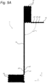
- Figure 5A shows a line pattern for determining dynamic properties in X and Y print directions according to an exemplary embodiment of the present invention.
- Figure 5A shows a detailed part of the pattern of Figure 1 .
- Figure 5A is 90° rotated as compared to Figure 1 , so as to be able to focus on details of lines 14, 15, 16 and 17.
- the step of a) depositing the pattern 1 comprises depositing a first line 14 and a subsequent second line 15 at an angle ⁇ between 0° and 180° degrees to the first line.
- the angle ⁇ is 90°.
- the step of c) analysing one or more geometric features comprises localizing perturbations p4, p5, p6 at the beginning of the second line 15, and determining a centre line of the perturbations, and determining line width variations of the perturbations.
- the step of d) determining one or more printer properties then comprises determining dynamic properties in X and Y print directions based on an oscillation of the center line and the line width variations.
- the perturbations p4, p5, p6 of the second line 15 reveal a dynamic mode of oscillation of e.g. the print head of the FFF printer, or of the motion system of the FFF printer.
- the first line 14 is preceded by a pattern 17 to excite the motion system. The beginning of the first line 14 reveals that the print head oscillates whilst moving along the X-direction when depositing the first line 14.
- Figure 5B shows a zoomed in view of the perturbations p4, p5 and p6.
- a center line 51 is determined.
- the center line 51 may have an oscillatory behaviour.
- a width w1, w2 of the line 15 may vary in the printing direction, i.e. w1 ⁇ w2.
- Variations in width may be due to an oscillation of the print head in a direction parallel to the printing direction. Such an oscillation will avoid the print head from printing a constant line width due to variations in speed of the nozzle relative to the support.
- the eigenmode By analysing the perturbations p4, p5, p6 and the line width variations w1, w2, the eigenmode can be identified. To further enhance the analysis, perturbations p1, p2 and p3 in the line 14 can analysed.
- the angle ⁇ between line 14 and 15 can be chosen to identify particular shapes of the eigenmodes under investigation. In this particular embodiment the angle ⁇ is approximately 90° degrees so that the first and second lines 14, 15 are substantially orthogonal.
- the perturbations p1, p2, p3, p4, p5 and p6 reveal eigen frequencies, of the FFF printer, such as eigen frequencies of the gantry for example.
- eigen frequencies of the FFF printer
- the shape of the perturbations i.e. are they variations in line width or in the center line
- the distance between p4, p5 and p6 and/or w1 and w2 can be determined.
- first straight line 14 may be preceded by a first meandering start section 16 substantially perpendicular to the first straight line 14.
- the second straight line 15 may be preceded by a second meandering start section 17 substantially perpendicular to the second straight line 15.
- 3D printers such as FFF printers
- FFF printers comprise a print head provided with one or more nozzles capable of printing different materials, colours etc.
- small manufacturing tolerances may be present, and the nozzles may not be perfectly aligned with one another.
- the method of the present invention can be utilized by considering a pattern 1 as shown in Figure 6 .
- the step of a) depositing the pattern 1 may further comprise depositing a first circle 18 with a first nozzle (not shown) and a second circle 19 with a second nozzle (not shown), the second circle 19 being larger than the first circle 18 as well as being concentric thereto.
- first and second circles 18, 19 are intended to be concentric as specified in a predefined model. Also, as depicted, the second circle 18 has a larger radius R2 than a radius R1 of the first circle 18.
- the step of c) analysing the one or more geometric features then comprises analysing/identifying, i.e. in the scanned image, a first and second centre point CP1, CP2 of the first and second circle 18, 19 respectively.
- the step of d) determining one or more printer properties then comprises determining X and Y offset error between the first and the second nozzle based on the first and second centre points CP1, CP2.
- the first and second circles 18, 19 allow the first and second centre points CP1, CP2 to be conveniently located and accurately analysed in the scanned image of the pattern 1. Once the first and second centre points CP1, CP2 have been identified, the offset between the centres point CP1, CP2 can be determined, which is a measure of the X and Y offset between the first and the second nozzle.
- the step of a) depositing the pattern 1 may further comprise depositing a first polygon (not shown) with a first nozzle (not shown) and a second polygon (not shown) with a second nozzle (not shown), the second polygon being larger than the first polygon as well as being concentric thereto.
- the step of c) analysing the one or more geometric features then comprises analysing/identifying, i.e. in the scanned image, a first and second centre point of the first and second polygon respectively.
- the step of d) determining one or more printer properties then comprises determining X and Y offset between the first and the second nozzle based on the first and second centre points.
- step of step of c) and d) are then performed analogously as outlined above with regard to analysed/identified third and fourth centre points CP3, CP4 of the third and fourth circles 20, 21 respectively, and determining X and Y offset between the first and the second nozzle based on the third and fourth centre points CP2, CP3.
- the X and Y offset between the first and the second nozzles could be determined by, for example, taking the mean of the offset determined based on the first and second centre points CP1, CP2, and the offset determined based on the third and fourth centre points CP3, CP4.
- one or more geometric features of the deposited pattern 1 in the scanned image are analysed, so that one or more printer properties can be determined based on these geometric features. From this it is readily evident that image quality of the scanned image must be sufficient to accurately identify these geometric features.
- the method further comprises increasing contrast of the scanned image prior to the step of analysing the one or more geometric features. That is, once a scanned image of the pattern 1 is available as a result of method step b), then this scanned image may be improved by increasing contrast of the scanned image prior to the step of c) analysing the one or more geometric features. According to this embodiment, increasing contrast allows for enhanced definition of the pattern 1 in that the one or more lines in the scanned image are easier to identify and non- relevant areas are disregarded from further processing.
- Figure 7 shows a magnified portion of a scanned image of the pattern 1.
- Figure 8 shows a magnified portion of a contrast modified scanned image of the image of Figure 7 .
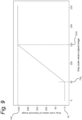
- Figure 9 shows a mapping function for grey scales values for improving contrast of a scanned image according to an embodiment of the present invention.
- an embodiment is provided wherein grey scale values of the original scanned image are mapped to new grey scale values according to some function, thereby obtaining the contrast modified scanned image of Figure 8 .
- Such mapping may involve rounding grey scale values upward or downward to reduce the number of different grey scale values.
- Such a reduction of grey scale values would enhance the definition of the edge E as the modified transient zone Z2 comprises fewer grey scale values.
- a grey scale value considered here are associated with a single pixel in the scanned image. So, for simplicity, when referring to a grey scale value than this implies a grey scale value of a pixel in the scanned image.
- step of increasing contrast of the scanned image comprises the step of
- a lowest range of grey scale values are set to a fixed lowest single value, i.e. the lowest grey scale value V L .
- V L the lowest grey scale value
- all grey scale values below 50 are simply rounded down to the value 0, so this may be viewed as a rounding down operation of the grey scale values below the lowest threshold grey scale value, TV L .
- a highest range of grey scale values are then set to a fixed highest single value, i.e. the highest grey scale value, V H .
- V H the highest grey scale value
- the noise i.e. the irrelevant data
- the noise is considerably reduced so that there will be a clearer definition of patterns and background.
- the pattern 1 may be represented in a scanned image by dark lines on a lighter background or by lighter lines on a dark background. So as shown in Figure 7 and 8 , the pattern 1 is in these embodiments represented as black lines on a white background.
- the grey scale values below the lowest threshold grey scale value TV L may then be considered as "black” wherein the grey scale values above the highest threshold grey scale value TV H may be seen as "white”.
- the step of a) depositing the pattern 1 of one or more lines on the support 2 comprises depositing the pattern 1 in a lighter colour than a colour of the support 2. Doing so minimizes reflection of light coming from the imaging device by reduced gloss of the lighter coloured pattern 1. Furthermore, a darker coloured support 2 prevents formation of shadows by the pattern 1 on the support 2.
- the pattern 1 may be deposited using a white or silver coloured filament material on a substantially black support 2, thereby minimizing gloss of the pattern 1 and the formation of shadows by the pattern 1 on the support 2.
- the step of increasing contrast of the scanned image further comprises the step of mapping all grey scale values between the lower threshold grey scale value, TV L , and the higher threshold grey scale value, TV H , according to a linear map with a non-zero gradient.
- a mapping as depicted in Figure 9 is used, e.g. a linear map between TV L and TV H .
- Such a map may improve distribution of grey scale value by "pulling" and “pushing" grey scale values downward and upward, respectively, from their original values for improving contrast of the scanned image.
- a non-linear map may considered for improving contrast of the scanned image of the pattern 1.
- a line width of a pattern line at a certain location is determined by defining a center line of the pattern line, drawing a perpendicular line (a line perpendicular to the center line) at the certain location and defining a graph of the grey scale values of the pixels along the perpendicular line. That graph will be a stepped function because of concrete grey scales of the pixels along the perpendicular line. Now curve fitting can be applied to get a smooth line across the stepped function. This smooth function, together with a predefined background grey scale level, can be used to determine the line width. In this way the line width of a deposited line can be determined on a subpixel level which is more accurate than on pixel level.
- the imaging device for use in the method of the present invention may exhibit scanning errors, inaccuracies, inconsistencies and the like, which in many cases occurs when inexpensive imaging devices (e.g. cameras) are used. These scanning errors may be introduced by optics and electronics of limited quality. Also, imaging devices may still use movable parts and mechanisms exhibiting mechanical tolerances, misalignments, offsets etc.
- the method should not rely on using high-end imaging devices to achieve a desired level of scanning accuracy and consistency. So, for situations where e.g. an optical scanner provides limited scanning quality, there is a need for dealing with scanning inaccuracies effectively to obtain an accurate representation of the pattern 1 in the scanned image thereof.
- Figures 10 and 11 An advantageous technique for dealing with imaging inaccuracies is depicted in Figures 10 and 11 , wherein Figure 10 shows an example of a reference pattern P to be scanned by the imaging device, and wherein Figure 11 shows an example of an imaging error map M identifying scanning errors introduced in the scanned reference pattern.
- step of b) further comprises making an image of a reference pattern P using the imaging device to produce a reference image, i.e. an image obtained from the reference pattern, and determining an imaging error map M between the reference pattern and the reference image.
- the method then continues by compensating the scanned image of the pattern 1 for scanning errors based on the imaging error map.
- the imaging error map obtained may be viewed as a difference between the reference pattern P and the scanned reference pattern.
- the reference pattern P may comprise a plurality of reference features r1, r2, e.g. a regular arrangement of dots r1, r2.
- an imaging error map M may be generated to identify positional shift/drift of the plurality of reference features r1, r2.
- the imaging error map M may be viewed as a vector field showing original positions of the plurality of reference feature r1, r2 in the reference pattern P that was scanned, and further showing shifted positions of each of the plurality of shifted reference features r1', r2' in the scanned reference image. Therefore, the imaging error map M may be seen as the original reference pattern P being overlaid by the scanned reference image.
- the imaging error map M obtained by the method need not show a uniform distribution of errors introduced into scanned images.
- another area A2 of the reference pattern P may be significantly more distorted as a corresponding scanned area A2' in the imaging error map M.
- the method may be performed by a person operating the FFF printer and the imaging device, wherein the support 2 with the pattern 1 may be removed from the FFF printer and subsequently arranged on or in front of the imaging device, e.g. a flatbed optical scanner.
- the image generated by the imaging device may then be copied manually or automatically onto a computer system comprising a processing unit 25 configured for analysing one or more geometric features of the pattern 1 in the image and determining the one or more printer properties of the FFF printer based the one or more geometric features.
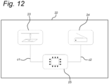
- a system 22 may comprise an FFF printer 23, an imaging device 24, and a processing unit 25 communicatively connected to the FFF printer 23 and the imaging device 24 (e.g. flatbed scanner, camera, webcam etc.) through communication channels c1, c2.
- the processing unit 25 may also be configured to control the FFF printer 23 to deposit a pattern 1 of one or more lines on a support 2 of the FFF printer.
- the processing unit 25 may be configured to control the imaging device 24 to make an image of the deposited pattern 1 on the support 2. Furthermore, the processing unit 25 may be configured to:
- the system 22 mentioned above allows for efficient and targeted analysis of various printer characteristics such as printer dynamics, orthogonality of printer axes, scaling and offset errors in various print directions, as well as hysteresis phenomena.
- the system 22 can therefore be used to facilitate comprehensive analysis of printer characteristics and behaviour for the purpose of quality control and calibration of FFF printers.
Landscapes
- Chemical & Material Sciences (AREA)
- Engineering & Computer Science (AREA)
- Materials Engineering (AREA)
- Manufacturing & Machinery (AREA)
- Physics & Mathematics (AREA)
- Mechanical Engineering (AREA)
- Optics & Photonics (AREA)
- Accessory Devices And Overall Control Thereof (AREA)
- Ink Jet (AREA)
Description
- The present invention relates to a method of determining one or more printer properties of an FFF printer. The invention also relates to a system for determining one or more printer properties of an FFF printer. Examples of such properties are X/Y scaling and orthogonality, X/Y/Z dynamic properties, nozzle offset errors, and hysteresis.
- US patent application
US 2016/0059491 A1 discloses a method of compensating a coordinate offset of a print nozzle. This method is adapted for a three-dimensional printing apparatus that includes a platform, a first nozzle, and a second nozzle. The first nozzle is configured to feed a first forming material and the second nozzle is configured to feed a second forming material. The coordinate offset compensating method includes receiving a calibration model associated with a plurality of compensation parameters. Each of the compensation parameters corresponds to an offset value between the first nozzle and the second nozzle under a reference printing coordinate. The first nozzle and the second nozzle are controlled to print a testing three-dimensional object on the platform according to the calibration model. The testing three-dimensional object includes a plurality of correlation structures respectively corresponding to the compensation parameters, and each correlation structure includes a first sub-structure and a second sub-structure. The first sub-structure is formed of the first forming material, and the second sub-structure is formed of the second forming material. One of the compensation parameters, which corresponds to one of the correlation structures, is selected according to a joint level between the first sub-structure and the second sub-structure of the correlation structure. The reference printing coordinate of the first nozzle or the second nozzle is compensated according to one of the compensation parameters selected according to the testing three-dimensional object. In an embodiment the image capturing unit to capture an image of the testing three-dimensional object on the platform and identifies the joint level of each correlation structure through image processing and analysis. -
US2018/093420A1 discloses a method of determining printer properties of an FFF printer according to the preamble of the appendedclaim 1. Prior art methods such as described above for compensating nozzle offset requires a plurality of compensation parameters from which a best compensation parameter is selected that produces the best joint level between the first and second substructures. One problem with such a compensation method is that a plurality of compensation parameters need to be generated, which may or may not have be as relevant because of e.g. limited detailed knowledge of printer performance or behaviour. - The present invention aims to provide a method of determining printer properties of a Fused Filament Fabrication (FFF) printer. The method provides efficient and targeted analysis of various printer characteristics such as printer dynamics, orthogonality, scaling and offset errors, and hysteresis phenomena. As such, the method of the present invention provides comprehensive analysis for quantifying printer characteristics and behaviour in an efficient manner, thereby facilitating research, calibration and quality control of 3D printers.
- According to the present invention, a method of determining one or more printer properties of an FFF printer according to the appended
claim 1, as well as a system according to the appendedclaim 9 is provided. - The above method allows for efficient and targeted analysis of printer properties by depositing the pattern on a support and subsequently making an image of the deposited line patterns using the imaging device. The obtained image is subsequently analysed for one or more geometric features of the deposited line pattern, wherein the one or more geometric features are indicative of specific printer behaviour. So, by choosing the pattern in a particular way allows specific printer properties/behaviour to be determined efficiently, thereby gaining further knowledge for improving calibration and quality control of the printers.
- In an embodiment, the support is a build plate of the FFF printer. In this embodiment, the pattern is printed directly on the build plate. Alternatively or additionally, (part of) the pattern may be printed on a surface of a printed object.
- Preferably, the pattern is a single line pattern. This results in a fast and simple process. However, it is noted that additional layers can be deposited on the first layer.
- The imaging device may be an external imaging device external from the FFF printer. Examples of such devices are optical scanners, such as flatbed scanners, or the imaging device could comprise external cameras, or cameras built into other equipment such as mobile phones. Alternatively, the imaging device may be built into the FFF printer itself. An example of such an embodiment is a camera arranged in the build chamber of the printer, or an optical scanner built into the printer. It is conceivable that a flatbed scanner is arranged just below a transparent build plate.
- In an embodiment, the pattern may, but need not, be chosen as a pattern of one or more connected or disconnected lines, each of which target specific printer behaviour through one or more geometric features of interest.
- When the obtained image is analysed for the one or more geometric features of interest, it may be the case that an image of the pattern lacks sufficient quality for accurately analysing the one or more geometric features. This may happen when, for example, an optical scanner produces scanned images having a relatively low feature resolution and definition. To facilitate accurate image analysis, an embodiment is provided wherein the method further comprises the step of increasing contrast of the image prior to the step of analysing the one or more geometric features. Improving contrast improves definition of e.g. edges of the pattern of lines in the image and as such the one or more geometric features will be easier to detect accurately.
- It is further worth noting that imaging device itself need not be manufactured accurately as a result of which an imaging device could introduce a large variety of unwanted imaging errors, distortions, inaccuracies etc. in the image. For example, a printed straight line on the support may be somewhat bent/distorted in the image because of mechanical and/or electronic errors introduced by the imaging device.
- To minimize adverse effects of mechanical and/or electronic inaccuracies of an imaging device, there is provided an embodiment wherein the method further comprises the step of making an image of a reference pattern using the imaging device to produce a reference image, and subsequently determining an imaging error map between the reference pattern and the reference image. The method then continues by compensating the image of the pattern for imaging errors based on the imaging error map.
- So, by making an image of a predefined reference pattern, various scanning errors, distortions, inaccuracies etc. between the scanned reference image and the reference pattern can be collected and turned into an imaging error map. This imaging error map, in turn, allows the scanned image of the pattern to be compensated such that the various errors introduced by the imaging device are removed. A particularly attractive advantage of this embodiment is that it is not required to utilize an expensive, high-end, high resolution imaging device for achieving accurate analysis of the one or more geometric features. So even though an inexpensive, low-end imaging device with sufficient resolution may introduce more scanning errors than an expensive, high-end, high resolution imaging device, obtaining an imaging error map as outlined above still allows for accurate analysis of the one or more geometric features regardless of the imaging device used.
- The present invention will be discussed in more detail below, with reference to the attached drawings, in which
-
Figure 1 shows a plan view of a pattern of lines for determining printer properties of an FFF printer according to an embodiment of the present invention; -
Figure 2 shows a method of determining printer properties of an FFF printer according to an embodiment of the present invention; -
Figure 3 shows a line pattern for determining scaling errors in X and Y print directions according to an embodiment of the present invention; -
Figure 4A shows a line pattern for determining hysteresis of printer movements according to an embodiment of the present invention; -
Figure 4B shows a detailed view of a part ofFigure 4A ; -
Figure 5A shows a line pattern for determining dynamic properties in X and Y print directions according to an embodiment of the present invention; -
Figure 5B shows a zoomed in part of thefigure 5A ; -
Figure 6 shows a line pattern for determining X and Y offset errors between a plurality of nozzles according to an embodiment of the present invention; -
Figure 7 shows a magnified portion of a scanned image according to an embodiment of the present invention; -
Figure 8 shows a magnified portion of a contrast modified scanned image according to an embodiment of the present invention; -
Figure 9 shows a mapping of grey scale values for improving contrast of a scanned image; -
Figure 10 shows a reference pattern according to an embodiment of the present invention; -
Figure 11 shows an imaging error map according to an embodiment of the present invention, and wherein -
Figure 12 shows a system for determining one or more printer properties of an FFF printer according to an embodiment of the present invention. - According to an embodiment of the present invention,
Figure 1 shows a plan view of apattern 1 of lines deposited on asupport 2 e.g. abuild plate 2, by an FFF printer (not shown). In an exemplary embodiment thesupport 2 is square or rectangular. As will be detailed further herein below, thepattern 1 of deposited print material in the form of one or more lines allows various printer properties to be determined by the method of the present invention, whereinFigure 2 shows a graphical representation of the method of determining such printer properties of the FFF printer. - As depicted, the method comprises the steps of a) depositing a
pattern 1 of one or more lines on asupport 2 using an FFF printer. That is, in this step an FFF printer is used to deposit a of printable material, e.g. extruding a filament material onto on thesupport 2. - Once the
pattern 1 has been deposited, the method continues and comprises the step of b) making an image of the depositedpattern 1 on thesupport 2 using an imaging device. In this step thesupport 2 may, for example, be removed from the FFF printer and arranged on the imaging device, e.g. a flatbed scanner to scan thepattern 1. As will be discussed in further detail later, it is also conceivable that the imaging device, e.g. a camera, is integrated into the FFF printer and thesupport 2 with the depositedpattern 1 can remain in the FFF printer. - When the image of the
pattern 1 has been obtained, the method continues with the step of c) analysing one or more geometric features of thepattern 1 in image. In this step the one or more lines in the scanned image comprise one or more geometric features of interest. Here, in this step analysing the one or more geometric features may also be construed as "extracting" one of more geometric features of interest from the scanned image. - Once the one or more geometric features have been analysed/extracted from the scanned image, the method proceeds with the step of d) determining one or more printer properties of the FFF printer based on using the one or more geometric features.
- The method steps a) to d) allow for efficient and targeted determination of printer properties by depositing the
pattern 1 on thesupport 2 and subsequently making an image of the depositedline pattern 1 using the imaging device. This scanned image is subsequently used for analysing/extracting one or more geometric features of thepattern 1 in the scanned image. The one or more geometric features can be seen as markers or indicators of specific printer behaviour. So, by choosing thepattern 1 in a particular way allows targeted determination of specific printer properties and behaviour of interest. Knowledge of these printer properties not only facilitates quality control of 3D printers, e.g. before the printer is shipped to customers, but specific printer behaviour may also be used for calibration purposes as specific printer behaviour may identify design errors/perturbations of the FFF printer. - Since the method may be performed on various FFF printers and for a large number of
patterns 1, it is advantageous to efficiently tag and identify a large numbers of image scans ofpatterns 1 as well as the various FFF printers with which the patterns were printed. To that end an embodiment is conceivable which is not according to the appended claims wherein the step of a) depositing thepattern 1 further comprises depositing a sequence of lines along an edge of thesupport 2 representing a bar code B, thereby tagging the depositedpattern 1 and linking it with a particular FFF printer with which thepattern 1 was printed. - There are various printer properties that may be of interest, for example, in an embodiment, the step of d) determining the one or more printer properties may comprise determining one or more of
- orthogonality of X and Y print axes, e.g. determining "squareness" of X-Y print axes;
- scaling errors in X and Y print direction, e.g. determining to what extend do predefined distances in a 3D computer model match real distances printed by the FFF printer;
- dynamic properties of the FFF printer in X, Y and Z print directions, e.g. eigenmodes and their corresponding eigenfrequencies and damping of the printer head; and
- hysteresis of print head movements, e.g. determine backlash in mechanical parts of the FFF printer.
- The above-mentioned properties of the FFF printer determine to a certain extend the accuracy at which an FFF printer is able to print a 3D model as specified. These properties also provide further information as to what part(s) of the FFF printer may require further design or manufacturing improvements, as well as providing information for calibration purposes.
- Referring to
Figure 1 , the orthogonality of X and Y axes may be determined by considering the following embodiment, wherein the step of a) depositing thepattern 1 further comprises depositing a first 3, a second 4 and a third 5 line pattern. The first 3 and second 4 line patterns are spaced apart in a Y direction, and the second 4 and the third 5 line patterns are spaced apart in an X direction, and wherein the first 3 and thethird line 5 patterns are spaced apart in both the Y and X direction. - This embodiment then continues with step of c) analysing one or more geometric features wherein two straight lines are analysed/determined, i.e. a first straight line L1 extending between geometric centres C1, C2 of the first 3 and the second 4 line patterns, and a second straight line L2 extending between geometric centres C2, C3 of the second 4 and the third 5 line pattern.
- Then based on the first and second straight lines L1, L2, the step of d) determining one or more printer properties comprises determining orthogonality of X and Y printer axes based on the first and second straight line L1, L2.
- In this embodiment each of the
line patterns line patterns third line patterns - For example, an exemplary FFF printer may comprise a nozzle head arranged on a gantry which is adapted to allow for movements of the nozzle head in X and Y directions that are perpendicular to each other. However, manufacturing errors and offsets of the gantry may not allow for perfect orthogonal movements of the nozzle head as intended. The angle Ω between the first and second straight lines L1, L2 as determined from the scanned image allows such manufacturing errors and offset of the gantry to be identified.
- As further depicted in
Figure 1 , the first 3, second 4, and third 5 line patterns may each comprise one or more circles and/or polygons. Such circles and/or polygons allow geometric centres thereof to be conveniently and accurately determined from the scanned image, and so in turn the first and second straight lines L1, L2 can be readily determined from the scanned image. For example, the first 3, second 4 and third 5 line patterns may each comprise an array arrangement of spaced apart circles and/or polygons, to facilitate and simplify systematic determination of geometric centres from the scanned image. - In the exemplary embodiment shown in
Figure 1 , each of the first 3, second 4 and third 5 line patterns comprises an array arrangement of a plurality of spaced apart circles, e.g. so where thefirst line pattern 3 comprises a plurality ofcircles second line pattern 4 comprises a plurality ofcircles third line pattern 5 comprises a plurality ofcircles Figure 1 it is shown that further first and second straight lines L1', L2' may be analysed that extend between the further geometric centres C1', C2', and C3' ofcircles - As further shown, in an embodiment the first, second and
third line patterns support 2, thereby ensuring that a nozzle head must travel into the corners so that orthogonality of the X and Y print axes, and so orthogonality of the gantry, can be investigated over a complete workspace of the FFF printer. - In an even further embodiment, it would be possible to deposit a
fourth line pattern 6 spaced apart in Y direction from thethird line pattern 4, spaced apart in X direction from thefirst line pattern 3 and spaced apart in X and Y direction from the second line pattern. A third straight line L3, seeFigure 1 , may then be drawn between a geometric centre C4 of thefourth line pattern 6 and the geometric centre C3 of thethird line pattern 5 as discussed earlier. - Then based on e.g. the second and third straight lines L2, L3, the step of d) determining one or more printer properties comprises determining orthogonality of X and Y printer axes based on the second and third straight line L2, L3. Furthermore, in other embodiments it is conceivable to investigate the accuracy at which parallel lines can be generated based on the first and third straight lines L1, L3.
- Like the first, second and
third line patterns fourth line pattern 6 may comprise a plurality of circles and/or polygons, e.g. a plurality of spaced apart circles 6a, 6b, 6c, 6d, possibly in an array arrangement as depicted. - From
Figure 1 it is also shown that such fourline patterns support 2, so that orthogonality of the X and Y print axes can be determined over a largest workspace of the FFF printer, e.g. the gantry. - Another interesting printer property of interest is related to scaling errors in X and Y directions, which refers to a difference that may occurs between a specified length of a line to be printed and the actual length printed by the FFF printer.
- Such scaling errors may be explained by referring to
Figure 3 , showing an embodiment of anarray line pattern 7 for determining scaling errors in X and Y print directions. As shown, thearray line pattern 7 may be obtained according to the embodiment of the method as outlined above. That is, by depositing the first 3, the second 4 and the third 5 line pattern, wherein the first 3 and second 4 line patterns are spaced apart in a Y direction, wherein the second 4 and the third 5 line patterns are spaced apart in an X direction, and wherein the first 3 and thethird line 5 patterns are spaced apart in the Y and X direction. - This embodiment then continues with the step of c) analysing one or more geometric features wherein two straight lines L1, L2 are drawn, i.e. the first straight line L1 extending between geometric centres C1, C2 of the first 3 and the second 4 line patterns, and a second straight line L2 extending between geometric centres C2, C3 of the second 4 and the third 5 line pattern.
- Based on the first and second straight lines L1, L2, the step of d) determining one or more printer properties then comprises determining a scaling error in the X and Y print direction based on the first and the second straight line L1, L2.
- As shown, in an embodiment each of the first, second and
third line patterns respective circle - From the first and the second straight line L1, L2 it is then possible to determine scaling errors in the X and Y direction as differences between lengths DL1, DL2 of the first and second straight line L1, L2 and what these lengths should be according to a model used as input to the FFF printer.
- In particular, in an embodiment a Y scaling error may be seen as a difference between a length DT1 of a prescribed first straight target line T1 and a length DL1 of the first straight line L1.
- Likewise, in an embodiment an X scaling error may be seen as a difference between a length DT2 of a prescribed second straight target line T2 and a length DL2 of the second straight line L2.
- So, by comparing lengths DL1, DL2 of the first and second straight lines L1, L2 to the respective lengths DT1, DT2 of the first and second straight target lines T1, T, scaling errors in the X and Y print directions may be determined.
- As further shown, the first and second straight target lines T1, T2 may be viewed as extending between geometric centres of
prescribed circles 3a', 4a', 5a'. - For further determining X and Y scaling errors, there is provided an embodiment wherein the
fourth line pattern 6 is deposited, e.g. as a circle 6a, and the third straight line L3 may then be analysed between geometric centre C4 of thefourth line pattern 6 and the geometric centre C3 of thethird line pattern 5. Furthermore, a fourth straight line L4 may be analysed between the geometric centre C4 of thefourth line pattern 6 and the geometric centre C1 of thefirst line pattern 3. - According to an embodiment, the step of d) determining the one or more printer properties may then comprise determining scaling errors in the X and Y print directions based on the first, second, third, and fourth straight lines L1, L2, L3, L4.
- In particular, in an exemplary embodiment the Y scaling error may be determined by determining a mean Y length, MY, of lengths DL1, DL3 of the first and third straight line L1, L3 and dividing this mean Y length, MY, by the length DT1 of the first straight target line T1.
- The X scaling error may likewise be determined by determining a mean X length, MX, between lengths DL2, DL4 of the second and fourth straight line L2, L4, and dividing this mean X length, MX, by the length DT2 of the second straight target line T2.
- In an even further embodiment, a first diagonal line S1 is drawn between the first and the
third line pattern fourth line pattern - It is worth nothing that distances between the
various line patterns line patterns support 2. - To continue with other properties of the printers, the method of the present invention further allows hysteresis to be examined for print head movements. To that end an embodiment is provided wherein the step of a) depositing the
pattern 1 comprises depositing a first set of two spaced apartparallel lines parallel lines lines lines Figure 4A shows thelines Figure 1 in more detail. The first set oflines line 8 andline 9 is referred to as d1 and a distance betweenline 10 andline 11 is referred to as d2. The distances d1 and d2 are taken using center lines of the printedlines -
Figure 4B shows a detailed view of a part ofFigure 4A . InFigure 4B thecenter lines lines target lines lines Figure 4B the distance d1target is the target distance between thecenter lines - Once d(I) is measured along the length of the
lines
(d1meas(I) ) - d1target) = e1(I), where e1(I) is the local distance error between thelines - Similar measuring steps are performed to determine a further local distance error using the second distance d2(I) between the two
lines
(d2meas(I) ) - d2target) = e2(I), where e2(I) is the local distance error between thelines - Subsequently, the step of d) determining one or more printer properties comprises determining hysteresis of print head movements based on a function H of the first and second local distance errors, i.e. H(e1(I),e2(I)).
- In a group of exemplary embodiments, the function H of the first and local second distance error e1, e2, may be:
- a maximum of the first and second local distance error e1(I), e2(I), e.g. max(e1(I), e2(I)); or
- a square root of the sum of squares of the maximum values of e1(I) and e2(I), e.g. H(e1(I),

- functions f1(α), f2(β) of the angles α and β, e.g. H(e1,e2) = f1(α)*e1m + f2(β)*e2m.
- Through this embodiment, it is possible to observe inaccuracies of printer head movements due to hysteresis as a function of the direction in which the printer head moves.
- As with the printer properties referred to earlier, the first and second distance errors e1(I), e2(I) can be accurately observed and determined from the scanned image of the first set of
lines lines - For further accuracy of observed hysteresis phenomena, an embodiment is conceivable wherein the previous steps are performed using three spaced apart parallel lines.
Figure 4A shows the additional lines used, seelines - According to the present invention, the scanned image of the
pattern 1 can also be used to determine dynamic properties and behaviour of an FFF printer, such as eigenmodes of a printer head for example. In light of this,Figure 5A shows a line pattern for determining dynamic properties in X and Y print directions according to an exemplary embodiment of the present invention. -
Figure 5A shows a detailed part of the pattern ofFigure 1 . Please note thatFigure 5A is 90° rotated as compared toFigure 1 , so as to be able to focus on details oflines pattern 1 comprises depositing afirst line 14 and a subsequentsecond line 15 at an angle γ between 0° and 180° degrees to the first line. In this example the angle γ is 90°. - In this embodiment according to the present invention the step of c) analysing one or more geometric features comprises localizing perturbations p4, p5, p6 at the beginning of the
second line 15, and determining a centre line of the perturbations, and determining line width variations of the perturbations. - The step of d) determining one or more printer properties then comprises determining dynamic properties in X and Y print directions based on an oscillation of the center line and the line width variations.
- The perturbations p4, p5, p6 of the
second line 15 reveal a dynamic mode of oscillation of e.g. the print head of the FFF printer, or of the motion system of the FFF printer. In the embodiment shown inFigure 5A , thefirst line 14 is preceded by apattern 17 to excite the motion system. The beginning of thefirst line 14 reveals that the print head oscillates whilst moving along the X-direction when depositing thefirst line 14. -
Figure 5B shows a zoomed in view of the perturbations p4, p5 and p6. When analysing the perturbations, first acenter line 51 is determined. As can be seen fromFigure 5B , thecenter line 51 may have an oscillatory behaviour. Next to the phenomena of this meandering center line, a width w1, w2 of theline 15 may vary in the printing direction, i.e. w1≠w2. Variations in width may be due to an oscillation of the print head in a direction parallel to the printing direction. Such an oscillation will avoid the print head from printing a constant line width due to variations in speed of the nozzle relative to the support. - By analysing the perturbations p4, p5, p6 and the line width variations w1, w2, the eigenmode can be identified. To further enhance the analysis, perturbations p1, p2 and p3 in the
line 14 can analysed. The angle γ betweenline second lines - It is worth noting that the perturbations p1, p2, p3, p4, p5 and p6 reveal eigen frequencies, of the FFF printer, such as eigen frequencies of the gantry for example. By analysing the shape of the perturbations (i.e. are they variations in line width or in the center line) information on the eigenmode is acquired, and by analysing the distance between p4, p5 and p6 and/or w1 and w2, the eigen frequencies can be determined.
- As further shown in
Figure 5A , the firststraight line 14 may be preceded by a firstmeandering start section 16 substantially perpendicular to the firststraight line 14. Likewise, the secondstraight line 15 may be preceded by a secondmeandering start section 17 substantially perpendicular to the secondstraight line 15. By printing these meanderingsections lines sections support 2 so as to avoid unwanted detachment of the material. - Many 3D printers, such as FFF printers, comprise a print head provided with one or more nozzles capable of printing different materials, colours etc. However, small manufacturing tolerances may be present, and the nozzles may not be perfectly aligned with one another. To identify misalignment and positional offset of two nozzles, the method of the present invention can be utilized by considering a
pattern 1 as shown inFigure 6 . - In particular, according to an embodiment the step of a) depositing the
pattern 1 may further comprise depositing afirst circle 18 with a first nozzle (not shown) and asecond circle 19 with a second nozzle (not shown), thesecond circle 19 being larger than thefirst circle 18 as well as being concentric thereto. - It is worth mentioning that in this step the first and
second circles second circle 18 has a larger radius R2 than a radius R1 of thefirst circle 18. - The step of c) analysing the one or more geometric features then comprises analysing/identifying, i.e. in the scanned image, a first and second centre point CP1, CP2 of the first and
second circle - Subsequently, the step of d) determining one or more printer properties then comprises determining X and Y offset error between the first and the second nozzle based on the first and second centre points CP1, CP2.
- In this embodiment, the first and
second circles pattern 1. Once the first and second centre points CP1, CP2 have been identified, the offset between the centres point CP1, CP2 can be determined, which is a measure of the X and Y offset between the first and the second nozzle. - Is noted that the above embodiment may also be considered in view of polygons instead of the first and
second circles pattern 1 may further comprise depositing a first polygon (not shown) with a first nozzle (not shown) and a second polygon (not shown) with a second nozzle (not shown), the second polygon being larger than the first polygon as well as being concentric thereto. - It is worth mentioning that in this step the first and second polygons are intended to be concentric as specified in a predefined model. The first and second polygons may, but need not, have identical shapes. The step of c) analysing the one or more geometric features then comprises analysing/identifying, i.e. in the scanned image, a first and second centre point of the first and second polygon respectively.
- Subsequently, the step of d) determining one or more printer properties then comprises determining X and Y offset between the first and the second nozzle based on the first and second centre points.
- To further increase accuracy of the X and Y offsets between a plurality of print nozzles of the FFF printer, it is of course conceivable to deposited a
third circle 20 with the first nozzle (not shown) and afourth circle 21 with the second nozzle (not shown), wherein thefourth circle 21 being larger than thethird circle 20 as well as being concentric thereto. The step of
step of c) and d) are then performed analogously as outlined above with regard to analysed/identified third and fourth centre points CP3, CP4 of the third andfourth circles - According to the present invention, one or more geometric features of the deposited
pattern 1 in the scanned image are analysed, so that one or more printer properties can be determined based on these geometric features. From this it is readily evident that image quality of the scanned image must be sufficient to accurately identify these geometric features. - In an embodiment the method further comprises increasing contrast of the scanned image prior to the step of analysing the one or more geometric features. That is, once a scanned image of the
pattern 1 is available as a result of method step b), then this scanned image may be improved by increasing contrast of the scanned image prior to the step of c) analysing the one or more geometric features. According to this embodiment, increasing contrast allows for enhanced definition of thepattern 1 in that the one or more lines in the scanned image are easier to identify and non- relevant areas are disregarded from further processing. - This pre-processing step of the image may be further explained by referring to
Figure 7 , which shows a magnified portion of a scanned image of thepattern 1.Figure 8 shows a magnified portion of a contrast modified scanned image of the image ofFigure 7 .Figure 9 shows a mapping function for grey scales values for improving contrast of a scanned image according to an embodiment of the present invention. - To transform an original scanned image, as depicted in
Figure 7 , to a contrast modified scanned image as shown inFigure 8 , an embodiment is provided wherein grey scale values of the original scanned image are mapped to new grey scale values according to some function, thereby obtaining the contrast modified scanned image ofFigure 8 . Such mapping may involve rounding grey scale values upward or downward to reduce the number of different grey scale values. Such a reduction of grey scale values would enhance the definition of the edge E as the modified transient zone Z2 comprises fewer grey scale values. - It is noted that a grey scale value considered here are associated with a single pixel in the scanned image. So, for simplicity, when referring to a grey scale value than this implies a grey scale value of a pixel in the scanned image.
- In view of
Figure 9 , an embodiment of a method which is not according to the appended claims may be provided wherein the step of
increasing contrast of the scanned image comprises the step of - selecting a lower threshold grey scale value, TVL , and a higher threshold grey scale value, TVH, from all grey scale values in the scanned image;
- mapping all grey scale values that are equal to or smaller than the lower threshold grey scale value, TVL, to a lowest grey scale value, VL; and then
- mapping all grey scale values equal to or larger than the higher threshold grey scale value, TVH, to a highest grey scale value, VH.
- In this embodiment a lowest range of grey scale values are set to a fixed lowest single value, i.e. the lowest grey scale value VL. As shown, all grey scale values below 50 are simply rounded down to the
value 0, so this may be viewed as a rounding down operation of the grey scale values below the lowest threshold grey scale value, TVL. - A highest range of grey scale values are then set to a fixed highest single value, i.e. the highest grey scale value, VH. As shown, all grey scale values above 150 rounded up to the
value 250, so this may be viewed as a rounding up operation or all of the grey scale values above the highest threshold grey scale value, TVH. - Through the above embodiment the noise, i.e. the irrelevant data, is considerably reduced so that there will be a clearer definition of patterns and background.
- It is worth noting that the
pattern 1 may be represented in a scanned image by dark lines on a lighter background or by lighter lines on a dark background. So as shown inFigure 7 and 8 , thepattern 1 is in these embodiments represented as black lines on a white background. The grey scale values below the lowest threshold grey scale value TVL may then be considered as "black" wherein the grey scale values above the highest threshold grey scale value TVH may be seen as "white". - Even though the
pattern 1 is depicted as black on white for keeping the figures easier to read, in real applications it may be advantageous to deposit thepattern 1 as one or more light coloured lines on a darkercoloured support 2. That is, in a preferred embodiment the step of a) depositing thepattern 1 of one or more lines on thesupport 2 comprises depositing thepattern 1 in a lighter colour than a colour of thesupport 2. Doing so minimizes reflection of light coming from the imaging device by reduced gloss of the lightercoloured pattern 1. Furthermore, a darkercoloured support 2 prevents formation of shadows by thepattern 1 on thesupport 2. In an exemplary embodiment thepattern 1 may be deposited using a white or silver coloured filament material on a substantiallyblack support 2, thereby minimizing gloss of thepattern 1 and the formation of shadows by thepattern 1 on thesupport 2. - Further steps for improving contrast of the scanned image are conceivable. For example, in an embodiment which is not according to the present claims the step of increasing contrast of the scanned image further comprises the step of mapping all grey scale values between the lower threshold grey scale value, TVL, and the higher threshold grey scale value, TVH, according to a linear map with a non-zero gradient. In this embodiment a mapping as depicted in
Figure 9 is used, e.g. a linear map between TVL and TVH. Such a map may improve distribution of grey scale value by "pulling" and "pushing" grey scale values downward and upward, respectively, from their original values for improving contrast of the scanned image. In alternative embodiments a non-linear map may considered for improving contrast of the scanned image of thepattern 1. - From
Figure 8 line widths, distances and angles between lines can accurately be determined. In an embodiment, a line width of a pattern line at a certain location is determined by defining a center line of the pattern line, drawing a perpendicular line (a line perpendicular to the center line) at the certain location and defining a graph of the grey scale values of the pixels along the perpendicular line. That graph will be a stepped function because of concrete grey scales of the pixels along the perpendicular line. Now curve fitting can be applied to get a smooth line across the stepped function. This smooth function, together with a predefined background grey scale level, can be used to determine the line width. In this way the line width of a deposited line can be determined on a subpixel level which is more accurate than on pixel level. - The imaging device for use in the method of the present invention may exhibit scanning errors, inaccuracies, inconsistencies and the like, which in many cases occurs when inexpensive imaging devices (e.g. cameras) are used. These scanning errors may be introduced by optics and electronics of limited quality. Also, imaging devices may still use movable parts and mechanisms exhibiting mechanical tolerances, misalignments, offsets etc.
- According to the present invention, the method should not rely on using high-end imaging devices to achieve a desired level of scanning accuracy and consistency. So, for situations where e.g. an optical scanner provides limited scanning quality, there is a need for dealing with scanning inaccuracies effectively to obtain an accurate representation of the
pattern 1 in the scanned image thereof. - An advantageous technique for dealing with imaging inaccuracies is depicted in
Figures 10 and 11 , whereinFigure 10 shows an example of a reference pattern P to be scanned by the imaging device, and whereinFigure 11 shows an example of an imaging error map M identifying scanning errors introduced in the scanned reference pattern. - Based on
Figure 10 and 11 , an embodiment is provided wherein the step of b) further comprises making an image of a reference pattern P using the imaging device to produce a reference image, i.e. an image obtained from the reference pattern, and determining an imaging error map M between the reference pattern and the reference image. - The method then continues by compensating the scanned image of the
pattern 1 for scanning errors based on the imaging error map. - This embodiment allows quick and accurate determination of scanning errors being introduced into images by the imaging device. The imaging error map obtained may be viewed as a difference between the reference pattern P and the scanned reference pattern.
- In the embodiment of
Figure 10 , the reference pattern P may comprise a plurality of reference features r1, r2, e.g. a regular arrangement of dots r1, r2. By making an image of the reference pattern P, an imaging error map M may be generated to identify positional shift/drift of the plurality of reference features r1, r2. As shown inFigure 11 , the imaging error map M may be viewed as a vector field showing original positions of the plurality of reference feature r1, r2 in the reference pattern P that was scanned, and further showing shifted positions of each of the plurality of shifted reference features r1', r2' in the scanned reference image. Therefore, the imaging error map M may be seen as the original reference pattern P being overlaid by the scanned reference image. - It is worth noting that the imaging error map M obtained by the method need not show a uniform distribution of errors introduced into scanned images. As depicted in
Figure 10 and 11 , there may be an area A1 of the reference pattern P that remains by and large the same as a corresponding scanned area A1' as shown in the imaging error map M. However, another area A2 of the reference pattern P may be significantly more distorted as a corresponding scanned area A2' in the imaging error map M. - According to the present invention, the method may be performed by a person operating the FFF printer and the imaging device, wherein the
support 2 with thepattern 1 may be removed from the FFF printer and subsequently arranged on or in front of the imaging device, e.g. a flatbed optical scanner. The image generated by the imaging device may then be copied manually or automatically onto a computer system comprising aprocessing unit 25 configured for analysing one or more geometric features of thepattern 1 in the image and determining the one or more printer properties of the FFF printer based the one or more geometric features. - However, it is also conceivable that the method can be automated by a system as shown in
Figure 12 . In the embodiment shown, asystem 22 may comprise anFFF printer 23, animaging device 24, and aprocessing unit 25 communicatively connected to theFFF printer 23 and the imaging device 24 (e.g. flatbed scanner, camera, webcam etc.) through communication channels c1, c2. Theprocessing unit 25 may also be configured to control theFFF printer 23 to deposit apattern 1 of one or more lines on asupport 2 of the FFF printer. - The
processing unit 25 may be configured to control theimaging device 24 to make an image of the depositedpattern 1 on thesupport 2. Furthermore, theprocessing unit 25 may be configured to: - receive an image of a pattern of one or more lines made by the FFF printer;
- analyse one or more geometric features of the
pattern 1 in the image; and to - determine the one or more printer properties of the FFF printer based the one or more geometric features.
- The
system 22 mentioned above allows for efficient and targeted analysis of various printer characteristics such as printer dynamics, orthogonality of printer axes, scaling and offset errors in various print directions, as well as hysteresis phenomena. Thesystem 22 can therefore be used to facilitate comprehensive analysis of printer characteristics and behaviour for the purpose of quality control and calibration of FFF printers. - The present invention has been described above with reference to a number of exemplary embodiments as shown in the drawings. Modifications and alternative implementations of some parts or elements are possible and are included in the scope of protection as defined in the appended claims.
Claims (9)
- A method of determining one or more printer properties of an FFF printer, comprising the steps of:a) depositing a pattern (1) of one or more lines on a support (2) using the FFF printer;b) making an image of the deposited pattern (1) on the support (2) using an imaging device; andc) analysing one or more geometric features of the pattern (1) in the image; andd) determining the one or more printer properties of the FFF printer based the one or more geometric features,characterised in that
the step of a) depositing the pattern (1) comprises depositing a first line (14) and a subsequent second line(15) at an angle (γ) between 0° and 180° degrees to the first line, and wherein the step of c) analysing one or more geometric features comprises:localizing perturbations (p4, p5, p6) at the beginning of the second line (15);determining a centre line of the perturbations;determining line width variations of the perturbations,and wherein the step of d) determining one or more printer properties comprises determining dynamic properties in X and Y print directions based on an oscillation of the center line and the line width variations. - The method according to claim 1, wherein the step of a) depositing the pattern further comprisesdepositing a first (3), a second (4) and a third (5) line pattern, wherein the first and second (3, 4) line patterns are spaced apart in a Y direction, wherein the second and the third (4, 5) line patterns are spaced apart in an X direction, and wherein the first and the third line patterns (3, 5) are spaced apart in the Y and X direction, wherein the step of c) analysing one or more geometric features comprisesdetermining a first straight line (L1) extending between geometric centres (C1, C2) of the first and the second line patterns (3, 4), and a second straight line (L2) extending between geometric centres (C2, C3) of the second and the third line pattern(4, 5); and wherein the step of d) determining one or more printer properties comprisesdetermining orthogonality of X and Y printer axes and/or scaling errors in X and Y print directions based on the first and second straight line (L1, L2).
- The method according to claim 2, wherein the first, second and third line patterns (3, 4, 5) each comprise one or more circles and/or polygons.
- The method according to claim 3, wherein the first, second and third line patterns (3, 4, 5) each comprise an array arrangement of spaced apart circles and/or polygons.
- The method according to any one of claims 1-4, wherein the step of a) depositing the pattern (1) comprises depositing a first set of two spaced apart parallel lines (8,9) and a second set of two spaced apart parallel lines (10, 11), wherein the first set of lines (8, 9) and the second set of lines (10, 11) are at an angle α between 0° and 90° with respect to each other and wherein the first set of lines (8, 9) are at an angle β between 0° and 90° with respect to the X axis, and wherein the step of c) analysing the one or more geometric features comprises:
determining a local distance error (e1) between the first set of parallel lines (8,9), the local distance error (e1) being a function of print length I along a print line, wherein:(d1meas(I) ) - d1target) = e1 (I), wherein d1meas(I) is a measured local distance between the first set of parallel lines, and d1target a targeted distance between the first set of parallel lines, anddetermining a local distance error (e1) between the second set of parallel lines (8,9), the local distance error (e2) being a function of print length I along a print line, wherein:(d2meas(I) ) - d2target) = e2(I), wherein d2meas(I) is a measured local distance between the second set of parallel lines, and d2target a targeted distance between the second set of parallel lines,and wherein the step of d) determining one or more printer properties comprises:
determining hysteresis of print head movements based on a function of the first and second local distance errors (e1, e2). - The method according to any one of claims 1-5, wherein the step of a) depositing the pattern (1) further comprises depositing a first circle (18) with a first nozzle and a second circle (19) with a second nozzle, the second circle (19) being larger than the first circle (18) and concentric to the first circle (18); and wherein the step of c) analysing the one or more geometric features comprisesanalysing first and second centre points (CP1, CP2) of the first and second circles (18, 19) respectively; and wherein the step of d) determining one or more printer properties comprisesdetermining an X and Y offset error between the first and the second nozzle based on the first and second centre points (CP1, CP2).
- The method according to any one of claims 1-5, wherein the step of a) depositing the pattern (1) further comprises depositing a first polygon with a first nozzle and a second polygon with a second nozzle, the second polygon being larger than the first polygon as well as being concentric thereto; and wherein the step of c) analysing the one or more geometric features then comprisesidentifying first and second centre points of the first and second polygon respectively; and wherein the step of d) determining one or more printer properties then comprisesdetermining an X and Y offset error between the first and the second nozzle based on the first and second centre points.
- The method according to anyone of claims 1-7, wherein the pattern (1) is a single layer pattern.
- A system (22) for determining one or more printer properties of an FFF printer, the system (22) comprising a processing unit (25), an FFF printer (23) and an imaging device (24) communicatively connected to the processing unit (25) through communication channels (c1, c2),wherein the FFF printer (23) is arranged to deposit a pattern (1) comprising a first line (14) and a subsequent second line(15) at an angle (γ) between 0° and 180° degrees to the first line, of one or more lines on a support (2) of the FFF printer (23),wherein the processing unit (25) is configured to control the imaging device (24) to make an image of the deposited pattern (1) on the support (2),wherein the processing unit (25) is configured to:- receive an image of the pattern made by the FFF printer;- localize perturbations (p4, p5, p6) at the beginning of the second line (15), and- determine a centre line of the perturbations;- determine line width variations of the perturbations, and to- determine dynamic properties in X and Y print directions based on an oscillation of the center line and the line width variations.
Applications Claiming Priority (2)
| Application Number | Priority Date | Filing Date | Title |
|---|---|---|---|
| NL2024127A NL2024127B1 (en) | 2019-10-31 | 2019-10-31 | Method of determining printer properties of an FFF printer |
| PCT/NL2020/050590 WO2021086174A1 (en) | 2019-10-31 | 2020-09-25 | Method of determining printer properties of an fff printer |
Publications (2)
| Publication Number | Publication Date |
|---|---|
| EP4051488A1 EP4051488A1 (en) | 2022-09-07 |
| EP4051488B1 true EP4051488B1 (en) | 2023-11-01 |
Family
ID=68654861
Family Applications (1)
| Application Number | Title | Priority Date | Filing Date |
|---|---|---|---|
| EP20781122.5A Active EP4051488B1 (en) | 2019-10-31 | 2020-09-25 | Method of determining printer properties of an fff printer |
Country Status (5)
| Country | Link |
|---|---|
| US (1) | US12370747B2 (en) |
| EP (1) | EP4051488B1 (en) |
| CN (1) | CN114599504A (en) |
| NL (1) | NL2024127B1 (en) |
| WO (1) | WO2021086174A1 (en) |
Families Citing this family (3)
| Publication number | Priority date | Publication date | Assignee | Title |
|---|---|---|---|---|
| JP2021160086A (en) * | 2020-03-30 | 2021-10-11 | 株式会社リコー | Three-dimensional molding device, control device, molding method and program |
| JP7855916B2 (en) * | 2022-05-12 | 2026-05-11 | セイコーエプソン株式会社 | 3D printing equipment |
| CN120096089B (en) * | 2025-03-20 | 2026-01-27 | 深圳拓竹科技有限公司 | Methods for determining tool head offset and 3D printers |
Family Cites Families (14)
| Publication number | Priority date | Publication date | Assignee | Title |
|---|---|---|---|---|
| US20060111807A1 (en) * | 2002-09-12 | 2006-05-25 | Hanan Gothait | Device, system and method for calibration in three-dimensional model printing |
| US10953609B1 (en) * | 2013-03-22 | 2021-03-23 | Markforged, Inc. | Scanning print bed and part height in 3D printing |
| TWI655108B (en) | 2014-09-03 | 2019-04-01 | 三緯國際立體列印科技股份有限公司 | Three-dimensional printing device and coordinate deviation compensation method thereof |
| US9216603B1 (en) * | 2015-01-23 | 2015-12-22 | Xerox Corporation | System and method for generation of test patterns for measurement of printhead to substrate separation in a printer |
| JP6791942B2 (en) * | 2015-07-13 | 2020-11-25 | ストラタシス リミテッド | Operation of printing nozzles in additional manufacturing and equipment |
| US10394202B2 (en) * | 2015-08-21 | 2019-08-27 | Voxel8, Inc. | 3D printer calibration and control |
| WO2017091830A1 (en) * | 2015-11-29 | 2017-06-01 | Mayo Foundation For Medical Education And Research | Systems and methods for quality control in 3d printing applications |
| US20180093420A1 (en) * | 2016-09-30 | 2018-04-05 | Robert Robert Olson | Calibrated 3-D Printing |
| US20180186080A1 (en) * | 2017-01-05 | 2018-07-05 | Velo3D, Inc. | Optics in three-dimensional printing |
| WO2018191627A1 (en) * | 2017-04-14 | 2018-10-18 | Desktop Metal, Inc. | Calibration of 3d printer via computer vision |
| US11014163B2 (en) * | 2017-04-14 | 2021-05-25 | Desktop Metal, Inc. | Calibration of 3D printer via computer vision |
| CN109109318A (en) * | 2017-06-26 | 2019-01-01 | 三纬国际立体列印科技股份有限公司 | Multi-light source adjusting device and using method thereof |
| US20190054700A1 (en) * | 2017-08-15 | 2019-02-21 | Cincinnati Incorporated | Machine learning for additive manufacturing |
| CA3124883A1 (en) * | 2019-01-08 | 2020-07-16 | Inkbit, LLC | Reconstruction of surfaces for additive manufacturing |
-
2019
- 2019-10-31 NL NL2024127A patent/NL2024127B1/en active
-
2020
- 2020-09-25 US US17/770,073 patent/US12370747B2/en active Active
- 2020-09-25 EP EP20781122.5A patent/EP4051488B1/en active Active
- 2020-09-25 CN CN202080074226.XA patent/CN114599504A/en active Pending
- 2020-09-25 WO PCT/NL2020/050590 patent/WO2021086174A1/en not_active Ceased
Also Published As
| Publication number | Publication date |
|---|---|
| NL2024127B1 (en) | 2021-07-19 |
| CN114599504A (en) | 2022-06-07 |
| US12370747B2 (en) | 2025-07-29 |
| WO2021086174A1 (en) | 2021-05-06 |
| US20220396034A1 (en) | 2022-12-15 |
| EP4051488A1 (en) | 2022-09-07 |
Similar Documents
| Publication | Publication Date | Title |
|---|---|---|
| DE69924936T2 (en) | Positioning system for hand scanner | |
| US12370747B2 (en) | Method and system for determining dynamic properties in X and Y print directions of an FFF printer using center line and line width variation analysis | |
| CN104180769B (en) | Systems and methods for efficient surface measurement using laser displacement sensors | |
| US6215914B1 (en) | Picture processing apparatus | |
| EP2549435B1 (en) | Segmentation of a depth map of printed circuit boards | |
| CN101655980B (en) | Method and system of image capture, alignment, and registration | |
| CN100526994C (en) | Transmission aligning mark combination and alignment method of light scribing device | |
| US20080112609A1 (en) | Position detecting method and device, patterning device, and subject to be detected | |
| JP4885584B2 (en) | Rangefinder calibration method and apparatus | |
| US8462407B2 (en) | Measuring separation of patterns, and use thereof for determining printer characteristics | |
| CN104597056B (en) | Method for detecting ink-jet printing ink dot positioning accuracy | |
| WO2018168757A1 (en) | Image processing device, system, image processing method, article manufacturing method, and program | |
| CN103245287B (en) | Image evaluation device, image evaluation method and non-transitory storage medium | |
| KR101677822B1 (en) | Scanning-electron-microscope image processing device and scanning method | |
| CN112985265A (en) | Linear array camera, precision compensation method thereof and storage medium | |
| CN116309063A (en) | Correction information generation method, image splicing method and device, and image acquisition system | |
| US7778788B2 (en) | Scanner based optical inspection system | |
| WO2025098007A1 (en) | Method for improving image stitching precision and positioning precision of portable printing/copying machine | |
| CN109186631A (en) | A kind of non-lineament scaling board for the calibration of white light scanning instrument | |
| JP2019020314A (en) | Line sensor optical axis adjustment device and line sensor optical axis adjustment method | |
| EP0198571B1 (en) | Method and system for patching original and extracting original-trimming data in scanner | |
| Kipman | Dot placement analysis using a line scan camera and rigid body rotation | |
| Gruber et al. | Novel high-precision photogrammetric scanning | |
| JP4367703B2 (en) | Orthographic projection image forming system | |
| KR20260038194A (en) | Splicing structure of image sensor, lens and macro camera |
Legal Events
| Date | Code | Title | Description |
|---|---|---|---|
| STAA | Information on the status of an ep patent application or granted ep patent |
Free format text: STATUS: UNKNOWN |
|
| STAA | Information on the status of an ep patent application or granted ep patent |
Free format text: STATUS: THE INTERNATIONAL PUBLICATION HAS BEEN MADE |
|
| PUAI | Public reference made under article 153(3) epc to a published international application that has entered the european phase |
Free format text: ORIGINAL CODE: 0009012 |
|
| STAA | Information on the status of an ep patent application or granted ep patent |
Free format text: STATUS: REQUEST FOR EXAMINATION WAS MADE |
|
| 17P | Request for examination filed |
Effective date: 20220513 |
|
| AK | Designated contracting states |
Kind code of ref document: A1 Designated state(s): AL AT BE BG CH CY CZ DE DK EE ES FI FR GB GR HR HU IE IS IT LI LT LU LV MC MK MT NL NO PL PT RO RS SE SI SK SM TR |
|
| DAV | Request for validation of the european patent (deleted) | ||
| DAX | Request for extension of the european patent (deleted) | ||
| GRAP | Despatch of communication of intention to grant a patent |
Free format text: ORIGINAL CODE: EPIDOSNIGR1 |
|
| STAA | Information on the status of an ep patent application or granted ep patent |
Free format text: STATUS: GRANT OF PATENT IS INTENDED |
|
| INTG | Intention to grant announced |
Effective date: 20230511 |
|
| GRAS | Grant fee paid |
Free format text: ORIGINAL CODE: EPIDOSNIGR3 |
|
| GRAA | (expected) grant |
Free format text: ORIGINAL CODE: 0009210 |
|
| STAA | Information on the status of an ep patent application or granted ep patent |
Free format text: STATUS: THE PATENT HAS BEEN GRANTED |
|
| RAP3 | Party data changed (applicant data changed or rights of an application transferred) |
Owner name: ULTIMAKER B.V. |
|
| RIN1 | Information on inventor provided before grant (corrected) |
Inventor name: VAN MANEN, RIJK |
|
| AK | Designated contracting states |
Kind code of ref document: B1 Designated state(s): AL AT BE BG CH CY CZ DE DK EE ES FI FR GB GR HR HU IE IS IT LI LT LU LV MC MK MT NL NO PL PT RO RS SE SI SK SM TR |
|
| REG | Reference to a national code |
Ref country code: GB Ref legal event code: FG4D |
|
| REG | Reference to a national code |
Ref country code: CH Ref legal event code: EP |
|
| REG | Reference to a national code |
Ref country code: IE Ref legal event code: FG4D Ref country code: NL Ref legal event code: FP |
|
| REG | Reference to a national code |
Ref country code: DE Ref legal event code: R096 Ref document number: 602020020360 Country of ref document: DE |
|
| REG | Reference to a national code |
Ref country code: LT Ref legal event code: MG9D |
|
| PG25 | Lapsed in a contracting state [announced via postgrant information from national office to epo] |
Ref country code: GR Free format text: LAPSE BECAUSE OF FAILURE TO SUBMIT A TRANSLATION OF THE DESCRIPTION OR TO PAY THE FEE WITHIN THE PRESCRIBED TIME-LIMIT Effective date: 20240202 |
|
| PG25 | Lapsed in a contracting state [announced via postgrant information from national office to epo] |
Ref country code: IS Free format text: LAPSE BECAUSE OF FAILURE TO SUBMIT A TRANSLATION OF THE DESCRIPTION OR TO PAY THE FEE WITHIN THE PRESCRIBED TIME-LIMIT Effective date: 20240301 |
|
| PG25 | Lapsed in a contracting state [announced via postgrant information from national office to epo] |
Ref country code: LT Free format text: LAPSE BECAUSE OF FAILURE TO SUBMIT A TRANSLATION OF THE DESCRIPTION OR TO PAY THE FEE WITHIN THE PRESCRIBED TIME-LIMIT Effective date: 20231101 |
|
| REG | Reference to a national code |
Ref country code: AT Ref legal event code: MK05 Ref document number: 1626737 Country of ref document: AT Kind code of ref document: T Effective date: 20231101 |
|
| PG25 | Lapsed in a contracting state [announced via postgrant information from national office to epo] |
Ref country code: AT Free format text: LAPSE BECAUSE OF FAILURE TO SUBMIT A TRANSLATION OF THE DESCRIPTION OR TO PAY THE FEE WITHIN THE PRESCRIBED TIME-LIMIT Effective date: 20231101 |
|
| PG25 | Lapsed in a contracting state [announced via postgrant information from national office to epo] |
Ref country code: ES Free format text: LAPSE BECAUSE OF FAILURE TO SUBMIT A TRANSLATION OF THE DESCRIPTION OR TO PAY THE FEE WITHIN THE PRESCRIBED TIME-LIMIT Effective date: 20231101 |
|
| PG25 | Lapsed in a contracting state [announced via postgrant information from national office to epo] |
Ref country code: LT Free format text: LAPSE BECAUSE OF FAILURE TO SUBMIT A TRANSLATION OF THE DESCRIPTION OR TO PAY THE FEE WITHIN THE PRESCRIBED TIME-LIMIT Effective date: 20231101 Ref country code: IS Free format text: LAPSE BECAUSE OF FAILURE TO SUBMIT A TRANSLATION OF THE DESCRIPTION OR TO PAY THE FEE WITHIN THE PRESCRIBED TIME-LIMIT Effective date: 20240301 Ref country code: GR Free format text: LAPSE BECAUSE OF FAILURE TO SUBMIT A TRANSLATION OF THE DESCRIPTION OR TO PAY THE FEE WITHIN THE PRESCRIBED TIME-LIMIT Effective date: 20240202 Ref country code: ES Free format text: LAPSE BECAUSE OF FAILURE TO SUBMIT A TRANSLATION OF THE DESCRIPTION OR TO PAY THE FEE WITHIN THE PRESCRIBED TIME-LIMIT Effective date: 20231101 Ref country code: BG Free format text: LAPSE BECAUSE OF FAILURE TO SUBMIT A TRANSLATION OF THE DESCRIPTION OR TO PAY THE FEE WITHIN THE PRESCRIBED TIME-LIMIT Effective date: 20240201 Ref country code: AT Free format text: LAPSE BECAUSE OF FAILURE TO SUBMIT A TRANSLATION OF THE DESCRIPTION OR TO PAY THE FEE WITHIN THE PRESCRIBED TIME-LIMIT Effective date: 20231101 Ref country code: PT Free format text: LAPSE BECAUSE OF FAILURE TO SUBMIT A TRANSLATION OF THE DESCRIPTION OR TO PAY THE FEE WITHIN THE PRESCRIBED TIME-LIMIT Effective date: 20240301 |
|
| PG25 | Lapsed in a contracting state [announced via postgrant information from national office to epo] |
Ref country code: SE Free format text: LAPSE BECAUSE OF FAILURE TO SUBMIT A TRANSLATION OF THE DESCRIPTION OR TO PAY THE FEE WITHIN THE PRESCRIBED TIME-LIMIT Effective date: 20231101 Ref country code: RS Free format text: LAPSE BECAUSE OF FAILURE TO SUBMIT A TRANSLATION OF THE DESCRIPTION OR TO PAY THE FEE WITHIN THE PRESCRIBED TIME-LIMIT Effective date: 20231101 Ref country code: PL Free format text: LAPSE BECAUSE OF FAILURE TO SUBMIT A TRANSLATION OF THE DESCRIPTION OR TO PAY THE FEE WITHIN THE PRESCRIBED TIME-LIMIT Effective date: 20231101 Ref country code: NO Free format text: LAPSE BECAUSE OF FAILURE TO SUBMIT A TRANSLATION OF THE DESCRIPTION OR TO PAY THE FEE WITHIN THE PRESCRIBED TIME-LIMIT Effective date: 20240201 Ref country code: LV Free format text: LAPSE BECAUSE OF FAILURE TO SUBMIT A TRANSLATION OF THE DESCRIPTION OR TO PAY THE FEE WITHIN THE PRESCRIBED TIME-LIMIT Effective date: 20231101 Ref country code: HR Free format text: LAPSE BECAUSE OF FAILURE TO SUBMIT A TRANSLATION OF THE DESCRIPTION OR TO PAY THE FEE WITHIN THE PRESCRIBED TIME-LIMIT Effective date: 20231101 |
|
| PG25 | Lapsed in a contracting state [announced via postgrant information from national office to epo] |
Ref country code: DK Free format text: LAPSE BECAUSE OF FAILURE TO SUBMIT A TRANSLATION OF THE DESCRIPTION OR TO PAY THE FEE WITHIN THE PRESCRIBED TIME-LIMIT Effective date: 20231101 |
|
| PG25 | Lapsed in a contracting state [announced via postgrant information from national office to epo] |
Ref country code: CZ Free format text: LAPSE BECAUSE OF FAILURE TO SUBMIT A TRANSLATION OF THE DESCRIPTION OR TO PAY THE FEE WITHIN THE PRESCRIBED TIME-LIMIT Effective date: 20231101 |
|
| PG25 | Lapsed in a contracting state [announced via postgrant information from national office to epo] |
Ref country code: SK Free format text: LAPSE BECAUSE OF FAILURE TO SUBMIT A TRANSLATION OF THE DESCRIPTION OR TO PAY THE FEE WITHIN THE PRESCRIBED TIME-LIMIT Effective date: 20231101 |
|
| PG25 | Lapsed in a contracting state [announced via postgrant information from national office to epo] |
Ref country code: SM Free format text: LAPSE BECAUSE OF FAILURE TO SUBMIT A TRANSLATION OF THE DESCRIPTION OR TO PAY THE FEE WITHIN THE PRESCRIBED TIME-LIMIT Effective date: 20231101 Ref country code: SK Free format text: LAPSE BECAUSE OF FAILURE TO SUBMIT A TRANSLATION OF THE DESCRIPTION OR TO PAY THE FEE WITHIN THE PRESCRIBED TIME-LIMIT Effective date: 20231101 Ref country code: IT Free format text: LAPSE BECAUSE OF FAILURE TO SUBMIT A TRANSLATION OF THE DESCRIPTION OR TO PAY THE FEE WITHIN THE PRESCRIBED TIME-LIMIT Effective date: 20231101 Ref country code: EE Free format text: LAPSE BECAUSE OF FAILURE TO SUBMIT A TRANSLATION OF THE DESCRIPTION OR TO PAY THE FEE WITHIN THE PRESCRIBED TIME-LIMIT Effective date: 20231101 Ref country code: DK Free format text: LAPSE BECAUSE OF FAILURE TO SUBMIT A TRANSLATION OF THE DESCRIPTION OR TO PAY THE FEE WITHIN THE PRESCRIBED TIME-LIMIT Effective date: 20231101 Ref country code: CZ Free format text: LAPSE BECAUSE OF FAILURE TO SUBMIT A TRANSLATION OF THE DESCRIPTION OR TO PAY THE FEE WITHIN THE PRESCRIBED TIME-LIMIT Effective date: 20231101 |
|
| REG | Reference to a national code |
Ref country code: DE Ref legal event code: R097 Ref document number: 602020020360 Country of ref document: DE |
|
| PLBE | No opposition filed within time limit |
Free format text: ORIGINAL CODE: 0009261 |
|
| STAA | Information on the status of an ep patent application or granted ep patent |
Free format text: STATUS: NO OPPOSITION FILED WITHIN TIME LIMIT |
|
| 26N | No opposition filed |
Effective date: 20240802 |
|
| PG25 | Lapsed in a contracting state [announced via postgrant information from national office to epo] |
Ref country code: SI Free format text: LAPSE BECAUSE OF FAILURE TO SUBMIT A TRANSLATION OF THE DESCRIPTION OR TO PAY THE FEE WITHIN THE PRESCRIBED TIME-LIMIT Effective date: 20231101 |
|
| PG25 | Lapsed in a contracting state [announced via postgrant information from national office to epo] |
Ref country code: SI Free format text: LAPSE BECAUSE OF FAILURE TO SUBMIT A TRANSLATION OF THE DESCRIPTION OR TO PAY THE FEE WITHIN THE PRESCRIBED TIME-LIMIT Effective date: 20231101 |
|
| PG25 | Lapsed in a contracting state [announced via postgrant information from national office to epo] |
Ref country code: MC Free format text: LAPSE BECAUSE OF FAILURE TO SUBMIT A TRANSLATION OF THE DESCRIPTION OR TO PAY THE FEE WITHIN THE PRESCRIBED TIME-LIMIT Effective date: 20231101 |
|
| PG25 | Lapsed in a contracting state [announced via postgrant information from national office to epo] |
Ref country code: LU Free format text: LAPSE BECAUSE OF NON-PAYMENT OF DUE FEES Effective date: 20240925 |
|
| PG25 | Lapsed in a contracting state [announced via postgrant information from national office to epo] |
Ref country code: IE Free format text: LAPSE BECAUSE OF NON-PAYMENT OF DUE FEES Effective date: 20240925 |
|
| REG | Reference to a national code |
Ref country code: CH Ref legal event code: U11 Free format text: ST27 STATUS EVENT CODE: U-0-0-U10-U11 (AS PROVIDED BY THE NATIONAL OFFICE) Effective date: 20251001 |
|
| PG25 | Lapsed in a contracting state [announced via postgrant information from national office to epo] |
Ref country code: FI Free format text: LAPSE BECAUSE OF FAILURE TO SUBMIT A TRANSLATION OF THE DESCRIPTION OR TO PAY THE FEE WITHIN THE PRESCRIBED TIME-LIMIT Effective date: 20231101 |
|
| PGFP | Annual fee paid to national office [announced via postgrant information from national office to epo] |
Ref country code: DE Payment date: 20250926 Year of fee payment: 6 |
|
| PGFP | Annual fee paid to national office [announced via postgrant information from national office to epo] |
Ref country code: NL Payment date: 20250909 Year of fee payment: 6 |
|
| PGFP | Annual fee paid to national office [announced via postgrant information from national office to epo] |
Ref country code: BE Payment date: 20250925 Year of fee payment: 6 Ref country code: GB Payment date: 20250923 Year of fee payment: 6 |
|
| PGFP | Annual fee paid to national office [announced via postgrant information from national office to epo] |
Ref country code: FR Payment date: 20250925 Year of fee payment: 6 |
|
| PG25 | Lapsed in a contracting state [announced via postgrant information from national office to epo] |
Ref country code: RO Free format text: LAPSE BECAUSE OF FAILURE TO SUBMIT A TRANSLATION OF THE DESCRIPTION OR TO PAY THE FEE WITHIN THE PRESCRIBED TIME-LIMIT Effective date: 20231101 |
|
| PGFP | Annual fee paid to national office [announced via postgrant information from national office to epo] |
Ref country code: CH Payment date: 20251001 Year of fee payment: 6 |
|
| PG25 | Lapsed in a contracting state [announced via postgrant information from national office to epo] |
Ref country code: CY Free format text: LAPSE BECAUSE OF FAILURE TO SUBMIT A TRANSLATION OF THE DESCRIPTION OR TO PAY THE FEE WITHIN THE PRESCRIBED TIME-LIMIT; INVALID AB INITIO Effective date: 20200925 |
|
| PG25 | Lapsed in a contracting state [announced via postgrant information from national office to epo] |
Ref country code: HU Free format text: LAPSE BECAUSE OF FAILURE TO SUBMIT A TRANSLATION OF THE DESCRIPTION OR TO PAY THE FEE WITHIN THE PRESCRIBED TIME-LIMIT; INVALID AB INITIO Effective date: 20200925 |
|
| PG25 | Lapsed in a contracting state [announced via postgrant information from national office to epo] |
Ref country code: TR Free format text: LAPSE BECAUSE OF FAILURE TO SUBMIT A TRANSLATION OF THE DESCRIPTION OR TO PAY THE FEE WITHIN THE PRESCRIBED TIME-LIMIT Effective date: 20231101 |