EP4050982A1 - Component mounting machine - Google Patents
Component mounting machine Download PDFInfo
- Publication number
- EP4050982A1 EP4050982A1 EP19950023.2A EP19950023A EP4050982A1 EP 4050982 A1 EP4050982 A1 EP 4050982A1 EP 19950023 A EP19950023 A EP 19950023A EP 4050982 A1 EP4050982 A1 EP 4050982A1
- Authority
- EP
- European Patent Office
- Prior art keywords
- attachable
- component
- mounting machine
- fpga
- detachable device
- Prior art date
- Legal status (The legal status is an assumption and is not a legal conclusion. Google has not performed a legal analysis and makes no representation as to the accuracy of the status listed.)
- Granted
Links
Images
Classifications
-
- H—ELECTRICITY
- H05—ELECTRIC TECHNIQUES NOT OTHERWISE PROVIDED FOR
- H05K—PRINTED CIRCUITS; CASINGS OR CONSTRUCTIONAL DETAILS OF ELECTRIC APPARATUS; MANUFACTURE OF ASSEMBLAGES OF ELECTRICAL COMPONENTS
- H05K13/00—Apparatus or processes specially adapted for manufacturing or adjusting assemblages of electric components
- H05K13/08—Monitoring manufacture of assemblages
- H05K13/0885—Power supply
-
- H—ELECTRICITY
- H05—ELECTRIC TECHNIQUES NOT OTHERWISE PROVIDED FOR
- H05K—PRINTED CIRCUITS; CASINGS OR CONSTRUCTIONAL DETAILS OF ELECTRIC APPARATUS; MANUFACTURE OF ASSEMBLAGES OF ELECTRICAL COMPONENTS
- H05K13/00—Apparatus or processes specially adapted for manufacturing or adjusting assemblages of electric components
- H05K13/08—Monitoring manufacture of assemblages
- H05K13/0882—Control systems for mounting machines or assembly lines, e.g. centralized control, remote links, programming of apparatus and processes as such
-
- H—ELECTRICITY
- H05—ELECTRIC TECHNIQUES NOT OTHERWISE PROVIDED FOR
- H05K—PRINTED CIRCUITS; CASINGS OR CONSTRUCTIONAL DETAILS OF ELECTRIC APPARATUS; MANUFACTURE OF ASSEMBLAGES OF ELECTRICAL COMPONENTS
- H05K13/00—Apparatus or processes specially adapted for manufacturing or adjusting assemblages of electric components
- H05K13/04—Mounting of components, e.g. of leadless components
- H05K13/0404—Pick-and-place heads or apparatus, e.g. with jaws
- H05K13/0408—Incorporating a pick-up tool
-
- H—ELECTRICITY
- H05—ELECTRIC TECHNIQUES NOT OTHERWISE PROVIDED FOR
- H05K—PRINTED CIRCUITS; CASINGS OR CONSTRUCTIONAL DETAILS OF ELECTRIC APPARATUS; MANUFACTURE OF ASSEMBLAGES OF ELECTRICAL COMPONENTS
- H05K13/00—Apparatus or processes specially adapted for manufacturing or adjusting assemblages of electric components
- H05K13/04—Mounting of components, e.g. of leadless components
- H05K13/0404—Pick-and-place heads or apparatus, e.g. with jaws
- H05K13/0408—Incorporating a pick-up tool
- H05K13/0409—Sucking devices
Definitions
- the present specification discloses a technique related to a component mounting machine that mounts a component on a circuit board.
- a component mounting machine in which a mounting head that exchangeably holds multiple suction nozzles is detachably (exchangeably) attached to a head holding section of the component mounting machine.
- the mounting head is provided with various electrical components such as a servo motor serving as a driving source, an electromagnetic valve that turns on/off the supply of negative pressure to a suction nozzle, and a pressure sensor that detects the negative pressure to be supplied, and wirings for the electrical components are connected to the component mounting machine side via a connector.
- Patent Literature 1 International Publication No. WO2015/019457
- the power supply to the mounting head is turned off in advance so that an operator can remove the mounting head from the component mounting machine when the operator exchanges a suction nozzle. This is because, when the mounting head is removed while power is supplied to the mounting head, a high voltage may be generated in the circuit on the power supply side to damage the electronic component.
- the mounting head is not necessarily removed from the component mounting machine for operation when an operator exchanges the suction nozzle, and the operation may be performed in a state in which the mounting head is attached to the component mounting machine.
- the suction nozzle can be safely exchanged even in a case where the power supply to the mounting head remains on, so that production can be resumed immediately after the exchange.
- the component mounting machine side does not know in advance whether the operator removes the mounting head from the component mounting machine when exchanging the suction nozzle, the operator always turns off the power supply to the mounting head when exchanging the suction nozzle. Therefore, it is necessary to resume the power supply to the mounting head after the suction nozzle is exchanged and to perform rebooting, because the power supply to the mounting head is turned off even though the power supply to the mounting head does not actually have to be turned off when the operator exchanges the suction nozzle in a state in which the mounting head is attached to the component mounting machine, and it takes time before production can be resumed.
- a component mounting machine that picks up a component supplied from a component supply device and mounts the component on a circuit board
- the component mounting machine including: a control device configured to control a component pickup and mounting operation of the component mounting machine; and multiple devices configured to execute the component pickup and mounting operation, in which at least one device out of the multiple devices is attachably and detachably attached to the component mounting machine and the attachable and detachable device is provided with an FPGA that operates each function of the attachable and detachable device by communicating with the control device, and the FPGA has a clock gating function of reducing an electric current flowing into the attachable and detachable device by stopping processing on a function that is not used, out of individual functions of the attachable and detachable device, when the attachable and detachable device is in a state capable of being removed by an operator.
- This configuration is a technical idea which focuses on the fact that the attachable and detachable device is provided with the FPGA operating each function of the attachable and detachable device by communicating with the control device of the component mounting machine, and which efficiently utilizes the clock gating function provided in the FPGA to solve the above-described problem.
- the FPGA provided in the attachable and detachable device uses the clock gating function to reduce an electric current flowing into the attachable and detachable device by stopping processing on a function that is not used, out of individual functions of the attachable and detachable device, when the attachable and detachable device is in a state capable of being removed by the operator.
- a component mounting machine includes control device 11 that controls a component pickup and mounting operation, and multiple devices that are used to execute the component pickup and mounting operation.
- the multiple devices that are used to execute the component pickup and mounting operation for example, component supply device 12, such as a tape feeder and a tray feeder, that supplies a component, mounting head 13 that attachably and detachably (exchangeably) holds a suction nozzle (not shown) which picks up the component supplied from component supply device 12, head moving device 14 that moves mounting head 13 in an XY direction, conveyor 15 that carries in/out a circuit board, component bottom-surface imaging camera 16 that images the component picked up by the suction nozzle from the bottom surface side thereof, and illumination device 17 that illuminates the bottom surface of the component which is an imaging target when the imaging of component bottom-surface imaging camera 16 are provided.
- a clamping device that clamps the circuit board carried in by conveyor 15, and a nozzle changer that stores
- Control device 11 of the component mounting machine is formed of a computer (CPU) as a main component, and controls the operations of the above-described multiple devices to execute the component pickup and mounting operation.
- CPU computer
- Mounting head 13 is provided with various electrical components such as at least one servo motor 21 serving as a driving source, electromagnetic valve 22 that turns on/off the supply of negative pressure to the suction nozzle, and pressure sensor 23 that detects the negative pressure to be supplied, and is also provided with mark imaging camera 24 that images a reference mark of the circuit board from above, LED illumination device 25 that illuminates an imaging target thereof, and the like. Wirings for various electrical components provided in mounting head 13 are connected to the side of control device 11 of the component mounting machine via a connector (not shown).
- Mounting head 13 which is a device attachably and detachably attached to the component mounting machine, is provided with Field Programmable Gate Array (FPGA) 26 that operates each function (each electrical component) of mounting head 13 by communicating with control device 11 of the component mounting machine.
- FPGA 26 is an array (gate array IC) of multiple logic circuits that are programmable (rewritable) in the field, and has clock gating function 27.
- Clock gating function 27 reduces an electric current flowing into mounting head 13 by stopping processing on a function that is not used, out of individual functions of mounting head 13, when mounting head 13 is in a state capable of being removed (the suction nozzle can be exchanged) by the operator.
- mounting head 13 is in the state capable of being removed (the suction nozzle can be exchanged) by the operator is determined by any of the following three determination methods 1 to 3.
- Control device 11 of the component mounting machine determines that mounting head 13 can be removed (the suction nozzle can be exchanged) by the operator, when the component mounting machine has stopped the component pickup and mounting operation (production), and causes FPGA 26 to operate clock gating function 27 by outputting a stop signal to FPGA 26. Whether the component mounting machine has stopped the component pickup and mounting operation (production) can be determined by control device 11 of the component mounting machine.
- a detecting section (not shown) that detects opening of a front cover of the component mounting machine is provided, and control device 11 of the component mounting machine determines that mounting head 13 can be removed (the suction nozzle can be exchanged) by the operator, when the detecting section has detected the opening of the front cover, and causes FPGA 26 to operate clock gating function 27 by outputting a stop signal to FPGA 26. It is considered that the operator has to open the front cover of the component mounting machine in order to remove mounting head 13 from the component mounting machine.
- Control device 11 of the component mounting machine determines that mounting head 13 can be removed (the suction nozzle can be exchanged) by the operator, when the operator has input an operation signal for performing operation such as the exchange of the suction nozzle with respect to mounting head 13 by operating an input device such as an operation panel (not shown), and causes FPGA 26 to operate clock gating function 27 by outputting a stop signal to FPGA 26.
- the processing on the functions that are not used is stopped.
- examples of the functions that are not used include a function of controlling mark imaging camera 24, a function of controlling the LED driver of LED illumination device 25, a function of controlling the IO input of pressure sensor 23, and a function of controlling the IO output of electromagnetic valve 22.
- FPGA 26 provided in mounting head 13 that is attachably and detachably attached to the component mounting machine continues only processing on servo motor 21, and uses clock gating function 27 to reduce the electric current flowing into mounting head 13 by stopping processing on the function that is not used, out of individual functions of mounting head 13.
- clock gating function 27 since the electric current flowing into mounting head 13 is reduced by clock gating function 27 although induced voltage is generated in the circuit on the power supply side when mounting head 13 is actually removed by the operator, the induced voltage generated in the circuit on the power supply side when mounting head 13 is removed by the operator is decreased, so that it is possible to prevent the electronic component from being damaged. Accordingly, when the operator exchanges the suction nozzle in a state in which the mounting head 13 is attached to the component mounting machine, production can be promptly resumed without performing rebooting of FPGA 26 after the exchange.
- mounting head 13 is provided with component side-surface imaging camera 31 that images a component picked up by the suction nozzle from the side-surface side thereof, and LED illumination device 32 that illuminates a side surface of the component which is an imaging target when the imaging of component side-surface imaging camera 31, in addition to mark imaging camera 24 and LED illumination device 25.
- the functions that are not used out of individual functions of mounting head 13 include a function of controlling component side-surface imaging camera 31 and a function of controlling the LED driver of LED illumination device 32, in addition to each function described in the first embodiment.
- the other configuration is the same as the configuration of the first embodiment. Also in the second embodiment described above, the same effect as in the first embodiment can be obtained.
- the present invention is not limited to the above-described first and second embodiments, and in a case where even a device other than mounting head 13 is attachable to and detachable from the component mounting machine and is provided with an FPGA that operates each function of the attachable and detachable device by communicating with control device 11 of the component mounting machine, the present invention can be applied and carried out for the attachable and detachable device.
- the present invention may be implemented by various changes within the scope that does not depart from the gist, for example, the configuration of the component mounting machine or the configuration of mounting head 13 may be appropriately changed.
- control device 11: control device, 12: component supply device, 13: mounting head (attachable and detachable device), 21: servo motor, 22: electromagnetic valve, 23: pressure sensor, 24: mark imaging camera, 25: LED illumination device, 26: FPGA, 27: clock gating function, 31: component side-surface imaging camera, 32: LED illumination device
Landscapes
- Engineering & Computer Science (AREA)
- Manufacturing & Machinery (AREA)
- Microelectronics & Electronic Packaging (AREA)
- Operations Research (AREA)
- Automation & Control Theory (AREA)
- Supply And Installment Of Electrical Components (AREA)
Abstract
Description
- The present specification discloses a technique related to a component mounting machine that mounts a component on a circuit board.
- As described in Patent Literature 1 (International Publication No.
WO2015/019457 ), a component mounting machine is disclosed in which a mounting head that exchangeably holds multiple suction nozzles is detachably (exchangeably) attached to a head holding section of the component mounting machine. In this case, the mounting head is provided with various electrical components such as a servo motor serving as a driving source, an electromagnetic valve that turns on/off the supply of negative pressure to a suction nozzle, and a pressure sensor that detects the negative pressure to be supplied, and wirings for the electrical components are connected to the component mounting machine side via a connector. - Patent Literature 1: International Publication No.
WO2015/019457 - For example, the power supply to the mounting head is turned off in advance so that an operator can remove the mounting head from the component mounting machine when the operator exchanges a suction nozzle. This is because, when the mounting head is removed while power is supplied to the mounting head, a high voltage may be generated in the circuit on the power supply side to damage the electronic component.
- However, when the power supply to the mounting head is turned off in advance, it takes time before the power supply to the mounting head is resumed after the exchange of the suction nozzle and rebooting is completed, so that it takes time before production can be resumed.
- In addition, the mounting head is not necessarily removed from the component mounting machine for operation when an operator exchanges the suction nozzle, and the operation may be performed in a state in which the mounting head is attached to the component mounting machine. In this case, when the mounting head is not removed from the component mounting machine, the suction nozzle can be safely exchanged even in a case where the power supply to the mounting head remains on, so that production can be resumed immediately after the exchange.
- However, since the component mounting machine side does not know in advance whether the operator removes the mounting head from the component mounting machine when exchanging the suction nozzle, the operator always turns off the power supply to the mounting head when exchanging the suction nozzle. Therefore, it is necessary to resume the power supply to the mounting head after the suction nozzle is exchanged and to perform rebooting, because the power supply to the mounting head is turned off even though the power supply to the mounting head does not actually have to be turned off when the operator exchanges the suction nozzle in a state in which the mounting head is attached to the component mounting machine, and it takes time before production can be resumed.
- In order to solve the above-described problem, there is provided a component mounting machine that picks up a component supplied from a component supply device and mounts the component on a circuit board, the component mounting machine including: a control device configured to control a component pickup and mounting operation of the component mounting machine; and multiple devices configured to execute the component pickup and mounting operation, in which at least one device out of the multiple devices is attachably and detachably attached to the component mounting machine and the attachable and detachable device is provided with an FPGA that operates each function of the attachable and detachable device by communicating with the control device, and the FPGA has a clock gating function of reducing an electric current flowing into the attachable and detachable device by stopping processing on a function that is not used, out of individual functions of the attachable and detachable device, when the attachable and detachable device is in a state capable of being removed by an operator.
- This configuration is a technical idea which focuses on the fact that the attachable and detachable device is provided with the FPGA operating each function of the attachable and detachable device by communicating with the control device of the component mounting machine, and which efficiently utilizes the clock gating function provided in the FPGA to solve the above-described problem. Specifically, the FPGA provided in the attachable and detachable device uses the clock gating function to reduce an electric current flowing into the attachable and detachable device by stopping processing on a function that is not used, out of individual functions of the attachable and detachable device, when the attachable and detachable device is in a state capable of being removed by the operator. In this case, since the electric current flowing into the attachable and detachable device is reduced by the clock gating function although induced voltage is generated in the circuit on the power supply side when the attachable and detachable device is actually removed by the operator, the induced voltage generated in the circuit on the power supply side when the attachable and detachable device is removed by the operator is decreased, so that it is possible to prevent the electronic component from being damaged. Accordingly, in a case where the attachable and detachable device is a mounting head, when the operator exchanges the suction nozzle in a state in which the mounting head is attached to the component mounting machine, production can be promptly resumed without performing rebooting after the exchange.
-
-
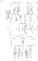
Fig. 1 is a block diagram showing a configuration of a control system of a mounting head of a first embodiment. -
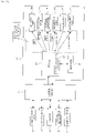
Fig. 2 is a block diagram showing a configuration of a control system of a mounting head of a second embodiment. - Hereinafter, two first and second embodiments disclosed in the present specification will be described.
- First, a first embodiment will be described with reference to
Fig. 1 . A component mounting machine includescontrol device 11 that controls a component pickup and mounting operation, and multiple devices that are used to execute the component pickup and mounting operation. Here, as the multiple devices that are used to execute the component pickup and mounting operation, for example,component supply device 12, such as a tape feeder and a tray feeder, that supplies a component, mountinghead 13 that attachably and detachably (exchangeably) holds a suction nozzle (not shown) which picks up the component supplied fromcomponent supply device 12,head moving device 14 that moves mountinghead 13 in an XY direction,conveyor 15 that carries in/out a circuit board, component bottom-surface imaging camera 16 that images the component picked up by the suction nozzle from the bottom surface side thereof, andillumination device 17 that illuminates the bottom surface of the component which is an imaging target when the imaging of component bottom-surface imaging camera 16 are provided. In addition, although not shown, for example, a clamping device that clamps the circuit board carried in byconveyor 15, and a nozzle changer that stores a suction nozzle for exchange are provided. -
Control device 11 of the component mounting machine is formed of a computer (CPU) as a main component, and controls the operations of the above-described multiple devices to execute the component pickup and mounting operation. -
Mounting head 13 is provided with various electrical components such as at least oneservo motor 21 serving as a driving source,electromagnetic valve 22 that turns on/off the supply of negative pressure to the suction nozzle, andpressure sensor 23 that detects the negative pressure to be supplied, and is also provided withmark imaging camera 24 that images a reference mark of the circuit board from above,LED illumination device 25 that illuminates an imaging target thereof, and the like. Wirings for various electrical components provided in mountinghead 13 are connected to the side ofcontrol device 11 of the component mounting machine via a connector (not shown). -
Mounting head 13, which is a device attachably and detachably attached to the component mounting machine, is provided with Field Programmable Gate Array (FPGA) 26 that operates each function (each electrical component) of mountinghead 13 by communicating withcontrol device 11 of the component mounting machine.FPGA 26 is an array (gate array IC) of multiple logic circuits that are programmable (rewritable) in the field, and hasclock gating function 27.Clock gating function 27 reduces an electric current flowing into mountinghead 13 by stopping processing on a function that is not used, out of individual functions of mountinghead 13, when mountinghead 13 is in a state capable of being removed (the suction nozzle can be exchanged) by the operator. - Here, whether mounting
head 13 is in the state capable of being removed (the suction nozzle can be exchanged) by the operator is determined by any of the following three determination methods 1 to 3. -
Control device 11 of the component mounting machine determines that mountinghead 13 can be removed (the suction nozzle can be exchanged) by the operator, when the component mounting machine has stopped the component pickup and mounting operation (production), and causesFPGA 26 to operateclock gating function 27 by outputting a stop signal toFPGA 26. Whether the component mounting machine has stopped the component pickup and mounting operation (production) can be determined bycontrol device 11 of the component mounting machine. - A detecting section (not shown) that detects opening of a front cover of the component mounting machine is provided, and
control device 11 of the component mounting machine determines that mountinghead 13 can be removed (the suction nozzle can be exchanged) by the operator, when the detecting section has detected the opening of the front cover, and causesFPGA 26 to operateclock gating function 27 by outputting a stop signal toFPGA 26. It is considered that the operator has to open the front cover of the component mounting machine in order to remove mountinghead 13 from the component mounting machine. -
Control device 11 of the component mounting machine determines that mountinghead 13 can be removed (the suction nozzle can be exchanged) by the operator, when the operator has input an operation signal for performing operation such as the exchange of the suction nozzle with respect to mountinghead 13 by operating an input device such as an operation panel (not shown), and causesFPGA 26 to operateclock gating function 27 by outputting a stop signal toFPGA 26. - In the first embodiment, since only processing on
servo motor 21 is continued and the functions except forservo motor 21 are not used, out of individual functions of mountinghead 13, when mountinghead 13 is in a state capable of being removed (the suction nozzle can be exchanged) by the operator, the processing on the functions that are not used is stopped. In this case, examples of the functions that are not used include a function of controllingmark imaging camera 24, a function of controlling the LED driver ofLED illumination device 25, a function of controlling the IO input ofpressure sensor 23, and a function of controlling the IO output ofelectromagnetic valve 22. - In the first embodiment described above, when mounting
head 13 is in a state capable of being removed by the operator,FPGA 26 provided in mountinghead 13 that is attachably and detachably attached to the component mounting machine continues only processing onservo motor 21, and usesclock gating function 27 to reduce the electric current flowing into mountinghead 13 by stopping processing on the function that is not used, out of individual functions of mountinghead 13. In this case, since the electric current flowing into mountinghead 13 is reduced byclock gating function 27 although induced voltage is generated in the circuit on the power supply side when mountinghead 13 is actually removed by the operator, the induced voltage generated in the circuit on the power supply side when mountinghead 13 is removed by the operator is decreased, so that it is possible to prevent the electronic component from being damaged. Accordingly, when the operator exchanges the suction nozzle in a state in which themounting head 13 is attached to the component mounting machine, production can be promptly resumed without performing rebooting ofFPGA 26 after the exchange. - A second embodiment will be described with reference to
Fig. 2 . It should be noted that the same reference numerals are assigned and the description thereof will be omitted and simplified for substantially the same portions as those in the above-described first embodiment, and description will be made mainly for different portions. - In the second embodiment shown in
Fig. 2 ,mounting head 13 is provided with component side-surface imaging camera 31 that images a component picked up by the suction nozzle from the side-surface side thereof, andLED illumination device 32 that illuminates a side surface of the component which is an imaging target when the imaging of component side-surface imaging camera 31, in addition tomark imaging camera 24 andLED illumination device 25. - Also in the second embodiment, when mounting
head 13 is in a state capable of being removed (the suction nozzle can be exchanged) by the operator, processing on a function that is not used, out of individual functions of mountinghead 13, is stopped so that an electric current flowing into mountinghead 13 is reduced. In this case, the functions that are not used out of individual functions of mountinghead 13 include a function of controlling component side-surface imaging camera 31 and a function of controlling the LED driver ofLED illumination device 32, in addition to each function described in the first embodiment. The other configuration is the same as the configuration of the first embodiment. Also in the second embodiment described above, the same effect as in the first embodiment can be obtained. - It should be noted that the present invention is not limited to the above-described first and second embodiments, and in a case where even a device other than mounting
head 13 is attachable to and detachable from the component mounting machine and is provided with an FPGA that operates each function of the attachable and detachable device by communicating withcontrol device 11 of the component mounting machine, the present invention can be applied and carried out for the attachable and detachable device. - In addition, it goes without saying that the present invention may be implemented by various changes within the scope that does not depart from the gist, for example, the configuration of the component mounting machine or the configuration of mounting
head 13 may be appropriately changed. - 11: control device, 12: component supply device, 13: mounting head (attachable and detachable device), 21: servo motor, 22: electromagnetic valve, 23: pressure sensor, 24: mark imaging camera, 25: LED illumination device, 26: FPGA, 27: clock gating function, 31: component side-surface imaging camera, 32: LED illumination device
Claims (6)
- A component mounting machine that picks up a component supplied from a component supply device and mounts the component on a circuit board, the component mounting machine comprising:a control device configured to control a component pickup and mounting operation of the component mounting machine; andmultiple devices configured to execute the component pickup and mounting operation,wherein at least one device out of the multiple devices is attachably and detachably attached to the component mounting machine and the attachable and detachable device is provided with an FPGA that operates each function of the attachable and detachable device by communicating with the control device, andthe FPGA has a clock gating function of reducing an electric current flowing into the attachable and detachable device by stopping processing on a function that is not used, out of individual functions of the attachable and detachable device, when the attachable and detachable device is in a state capable of being removed by an operator.
- The component mounting machine according to claim 1,
wherein the attachable and detachable device is a mounting head that attachably and detachably holds a suction nozzle configured to pick up the component supplied from the component supply device. - The component mounting machine according to claim 1 or 2,
wherein the control device is configured to determine that the attachable and detachable device can be removed by the operator, when the component mounting machine has stopped the component pickup and mounting operation, and to cause the FPGA to operate the clock gating function by outputting a stop signal to the FPGA. - The component mounting machine according to claim 1 or 2, further comprising:a detecting section configured to detect opening of a front cover of the component mounting machine,wherein the control device is configured to determine that the attachable and detachable device can be removed by the operator, when the detecting section has detected the opening of the front cover, and to cause the FPGA to operate the clock gating function by outputting a stop signal to the FPGA.
- The component mounting machine according to claim 1 or 2,
wherein the control device is configured to determine that the attachable and detachable device can be removed by the operator, when the operator has input an operation signal for performing operation with respect to the attachable and detachable device, and to cause the FPGA to operate the clock gating function by outputting a stop signal to the FPGA. - The component mounting machine according to any one of claims 1 to 5,wherein the attachable and detachable device includes a servo motor as at least one of the functions, andthe FPGA continues processing on the servo motor and stops processing on a function except for the servo motor, out of individual functions of the attachable and detachable device, when the attachable and detachable device is in the state capable of being removed by the operator.
Applications Claiming Priority (1)
| Application Number | Priority Date | Filing Date | Title |
|---|---|---|---|
| PCT/JP2019/042011 WO2021079512A1 (en) | 2019-10-25 | 2019-10-25 | Component mounting machine |
Publications (3)
| Publication Number | Publication Date |
|---|---|
| EP4050982A1 true EP4050982A1 (en) | 2022-08-31 |
| EP4050982A4 EP4050982A4 (en) | 2022-11-02 |
| EP4050982B1 EP4050982B1 (en) | 2025-09-03 |
Family
ID=75619752
Family Applications (1)
| Application Number | Title | Priority Date | Filing Date |
|---|---|---|---|
| EP19950023.2A Active EP4050982B1 (en) | 2019-10-25 | 2019-10-25 | Component mounting machine |
Country Status (5)
| Country | Link |
|---|---|
| US (1) | US11871522B2 (en) |
| EP (1) | EP4050982B1 (en) |
| JP (1) | JP7300606B2 (en) |
| CN (1) | CN114424689B (en) |
| WO (1) | WO2021079512A1 (en) |
Families Citing this family (1)
| Publication number | Priority date | Publication date | Assignee | Title |
|---|---|---|---|---|
| JP7300606B2 (en) * | 2019-10-25 | 2023-06-30 | 株式会社Fuji | Mounting machine |
Family Cites Families (15)
| Publication number | Priority date | Publication date | Assignee | Title |
|---|---|---|---|---|
| WO2000069241A1 (en) * | 1999-05-06 | 2000-11-16 | Matsushita Electric Industrial Co., Ltd. | Component mounting apparatus and method therefor |
| JP2006313806A (en) * | 2005-05-09 | 2006-11-16 | Matsushita Electric Ind Co Ltd | Electronic component mounting apparatus and power supply control method in electronic component mounting apparatus |
| KR101199173B1 (en) * | 2008-02-13 | 2012-11-07 | 산요 세미컨덕터 컴퍼니 리미티드 | Motor drive device |
| JP4604127B2 (en) | 2009-09-30 | 2010-12-22 | 富士機械製造株式会社 | Electronic circuit component mounting machine and electronic circuit assembly method |
| JP2011228472A (en) * | 2010-04-20 | 2011-11-10 | Panasonic Corp | Electronic components implementation device |
| WO2013065136A1 (en) | 2011-11-01 | 2013-05-10 | 富士通株式会社 | Power supply switching device, power supply unit, and computer system |
| US9677588B2 (en) * | 2012-01-20 | 2017-06-13 | Fuji Machine Mfg. Co., Ltd. | Component mounter mounting head holding device |
| JP5984284B2 (en) * | 2012-02-28 | 2016-09-06 | Jukiオートメーションシステムズ株式会社 | Component mounting apparatus and board manufacturing method |
| TWI478792B (en) * | 2012-12-27 | 2015-04-01 | Ueno Seiki Co Ltd | A method of moving the holding means, an electronic component holding means, and an electronic component handling means |
| DE102013101932A1 (en) * | 2013-02-27 | 2014-08-28 | Pilz Gmbh & Co. Kg | Safety switching device for on / fail-safe switching off of a technical system |
| JP6246212B2 (en) | 2013-08-08 | 2017-12-13 | 富士機械製造株式会社 | Component mounter |
| JP6348387B2 (en) * | 2014-09-22 | 2018-06-27 | スタンレー電気株式会社 | Control method for vehicle headlamp system |
| JP6568934B2 (en) * | 2015-04-16 | 2019-08-28 | 株式会社Fuji | Component mounter drive system |
| US10667451B2 (en) * | 2018-02-09 | 2020-05-26 | Fuji Corporation | Component mounter with a push function |
| JP7300606B2 (en) * | 2019-10-25 | 2023-06-30 | 株式会社Fuji | Mounting machine |
-
2019
- 2019-10-25 JP JP2021553875A patent/JP7300606B2/en active Active
- 2019-10-25 WO PCT/JP2019/042011 patent/WO2021079512A1/en not_active Ceased
- 2019-10-25 CN CN201980100657.6A patent/CN114424689B/en active Active
- 2019-10-25 US US17/770,524 patent/US11871522B2/en active Active
- 2019-10-25 EP EP19950023.2A patent/EP4050982B1/en active Active
Also Published As
| Publication number | Publication date |
|---|---|
| JP7300606B2 (en) | 2023-06-30 |
| WO2021079512A1 (en) | 2021-04-29 |
| EP4050982B1 (en) | 2025-09-03 |
| CN114424689B (en) | 2023-10-24 |
| EP4050982A4 (en) | 2022-11-02 |
| US11871522B2 (en) | 2024-01-09 |
| US20220408623A1 (en) | 2022-12-22 |
| CN114424689A (en) | 2022-04-29 |
| JPWO2021079512A1 (en) | 2021-04-29 |
Similar Documents
| Publication | Publication Date | Title |
|---|---|---|
| CN100496203C (en) | Electronic component mounting apparatus | |
| US9167701B2 (en) | Method of mounting electronic component | |
| EP3316670B1 (en) | Work unit power supply device | |
| US11871522B2 (en) | Component mounting machine | |
| JP2008186992A (en) | Electronic component mounting device | |
| US20170297848A1 (en) | Tape feeder holding device | |
| US20220087087A1 (en) | Management device, moving work device, mounting device, mounting system, and management method | |
| US10530223B2 (en) | Component mounter drive system | |
| JP6076790B2 (en) | Electronic component mounting equipment | |
| WO2016046967A1 (en) | Maintenance notification system and maintenance notification method | |
| JP2021174879A (en) | Power switch for board work system, board work line and power management method for board work line. | |
| CN105009705A (en) | Pressure control device, surface mounting machine and pressure control method | |
| JP6377136B2 (en) | Anti-substrate working machine, anti-substrate working system, and anti-substrate working method | |
| JP6793050B2 (en) | Surface mounter | |
| US10979240B2 (en) | Substrate work system | |
| EP3550950A1 (en) | Operation machine | |
| US20250374499A1 (en) | Substrate production machine and substrate production line | |
| US12342469B2 (en) | Management device, mounting system, and management method | |
| US10743450B2 (en) | Component supply unit and mounting device | |
| JP7854376B2 (en) | Installation mode determination system | |
| KR101425814B1 (en) | Apparatus for laser marking | |
| EP4734691A1 (en) | Component mounter and component mounting method | |
| JP7299142B2 (en) | Mounting machine | |
| JP7584047B2 (en) | Component mounting device and component mounting method | |
| US11868113B2 (en) | Servo amplifier system |
Legal Events
| Date | Code | Title | Description |
|---|---|---|---|
| STAA | Information on the status of an ep patent application or granted ep patent |
Free format text: STATUS: THE INTERNATIONAL PUBLICATION HAS BEEN MADE |
|
| PUAI | Public reference made under article 153(3) epc to a published international application that has entered the european phase |
Free format text: ORIGINAL CODE: 0009012 |
|
| STAA | Information on the status of an ep patent application or granted ep patent |
Free format text: STATUS: REQUEST FOR EXAMINATION WAS MADE |
|
| 17P | Request for examination filed |
Effective date: 20220422 |
|
| AK | Designated contracting states |
Kind code of ref document: A1 Designated state(s): AL AT BE BG CH CY CZ DE DK EE ES FI FR GB GR HR HU IE IS IT LI LT LU LV MC MK MT NL NO PL PT RO RS SE SI SK SM TR |
|
| A4 | Supplementary search report drawn up and despatched |
Effective date: 20221005 |
|
| RIC1 | Information provided on ipc code assigned before grant |
Ipc: H05K 13/08 20060101ALI20220928BHEP Ipc: H05K 13/04 20060101AFI20220928BHEP |
|
| DAV | Request for validation of the european patent (deleted) | ||
| DAX | Request for extension of the european patent (deleted) | ||
| P01 | Opt-out of the competence of the unified patent court (upc) registered |
Effective date: 20230328 |
|
| GRAP | Despatch of communication of intention to grant a patent |
Free format text: ORIGINAL CODE: EPIDOSNIGR1 |
|
| STAA | Information on the status of an ep patent application or granted ep patent |
Free format text: STATUS: GRANT OF PATENT IS INTENDED |
|
| INTG | Intention to grant announced |
Effective date: 20250513 |
|
| GRAS | Grant fee paid |
Free format text: ORIGINAL CODE: EPIDOSNIGR3 |
|
| GRAA | (expected) grant |
Free format text: ORIGINAL CODE: 0009210 |
|
| STAA | Information on the status of an ep patent application or granted ep patent |
Free format text: STATUS: THE PATENT HAS BEEN GRANTED |
|
| AK | Designated contracting states |
Kind code of ref document: B1 Designated state(s): AL AT BE BG CH CY CZ DE DK EE ES FI FR GB GR HR HU IE IS IT LI LT LU LV MC MK MT NL NO PL PT RO RS SE SI SK SM TR |
|
| REG | Reference to a national code |
Ref country code: CH Ref legal event code: EP |
|
| REG | Reference to a national code |
Ref country code: DE Ref legal event code: R096 Ref document number: 602019075381 Country of ref document: DE |
|
| REG | Reference to a national code |
Ref country code: IE Ref legal event code: FG4D |
|
| REG | Reference to a national code |
Ref country code: NL Ref legal event code: MP Effective date: 20250903 |
|
| PGFP | Annual fee paid to national office [announced via postgrant information from national office to epo] |
Ref country code: DE Payment date: 20251014 Year of fee payment: 7 |
|
| PG25 | Lapsed in a contracting state [announced via postgrant information from national office to epo] |
Ref country code: NO Free format text: LAPSE BECAUSE OF FAILURE TO SUBMIT A TRANSLATION OF THE DESCRIPTION OR TO PAY THE FEE WITHIN THE PRESCRIBED TIME-LIMIT Effective date: 20251203 |
|
| REG | Reference to a national code |
Ref country code: LT Ref legal event code: MG9D |
|
| PG25 | Lapsed in a contracting state [announced via postgrant information from national office to epo] |
Ref country code: FI Free format text: LAPSE BECAUSE OF FAILURE TO SUBMIT A TRANSLATION OF THE DESCRIPTION OR TO PAY THE FEE WITHIN THE PRESCRIBED TIME-LIMIT Effective date: 20250903 |
|
| PG25 | Lapsed in a contracting state [announced via postgrant information from national office to epo] |
Ref country code: HR Free format text: LAPSE BECAUSE OF FAILURE TO SUBMIT A TRANSLATION OF THE DESCRIPTION OR TO PAY THE FEE WITHIN THE PRESCRIBED TIME-LIMIT Effective date: 20250903 |
|
| PG25 | Lapsed in a contracting state [announced via postgrant information from national office to epo] |
Ref country code: GR Free format text: LAPSE BECAUSE OF FAILURE TO SUBMIT A TRANSLATION OF THE DESCRIPTION OR TO PAY THE FEE WITHIN THE PRESCRIBED TIME-LIMIT Effective date: 20251204 |
|
| PG25 | Lapsed in a contracting state [announced via postgrant information from national office to epo] |
Ref country code: SE Free format text: LAPSE BECAUSE OF FAILURE TO SUBMIT A TRANSLATION OF THE DESCRIPTION OR TO PAY THE FEE WITHIN THE PRESCRIBED TIME-LIMIT Effective date: 20250903 |
|
| PG25 | Lapsed in a contracting state [announced via postgrant information from national office to epo] |
Ref country code: LV Free format text: LAPSE BECAUSE OF FAILURE TO SUBMIT A TRANSLATION OF THE DESCRIPTION OR TO PAY THE FEE WITHIN THE PRESCRIBED TIME-LIMIT Effective date: 20250903 |
|
| PG25 | Lapsed in a contracting state [announced via postgrant information from national office to epo] |
Ref country code: BG Free format text: LAPSE BECAUSE OF FAILURE TO SUBMIT A TRANSLATION OF THE DESCRIPTION OR TO PAY THE FEE WITHIN THE PRESCRIBED TIME-LIMIT Effective date: 20250903 Ref country code: PL Free format text: LAPSE BECAUSE OF FAILURE TO SUBMIT A TRANSLATION OF THE DESCRIPTION OR TO PAY THE FEE WITHIN THE PRESCRIBED TIME-LIMIT Effective date: 20250903 |
|
| PG25 | Lapsed in a contracting state [announced via postgrant information from national office to epo] |
Ref country code: RS Free format text: LAPSE BECAUSE OF FAILURE TO SUBMIT A TRANSLATION OF THE DESCRIPTION OR TO PAY THE FEE WITHIN THE PRESCRIBED TIME-LIMIT Effective date: 20251203 |
|
| PG25 | Lapsed in a contracting state [announced via postgrant information from national office to epo] |
Ref country code: ES Free format text: LAPSE BECAUSE OF FAILURE TO SUBMIT A TRANSLATION OF THE DESCRIPTION OR TO PAY THE FEE WITHIN THE PRESCRIBED TIME-LIMIT Effective date: 20250903 |
|
| REG | Reference to a national code |
Ref country code: AT Ref legal event code: MK05 Ref document number: 1834786 Country of ref document: AT Kind code of ref document: T Effective date: 20250903 |
|
| PG25 | Lapsed in a contracting state [announced via postgrant information from national office to epo] |
Ref country code: NL Free format text: LAPSE BECAUSE OF FAILURE TO SUBMIT A TRANSLATION OF THE DESCRIPTION OR TO PAY THE FEE WITHIN THE PRESCRIBED TIME-LIMIT Effective date: 20250903 |
|
| PG25 | Lapsed in a contracting state [announced via postgrant information from national office to epo] |
Ref country code: SM Free format text: LAPSE BECAUSE OF FAILURE TO SUBMIT A TRANSLATION OF THE DESCRIPTION OR TO PAY THE FEE WITHIN THE PRESCRIBED TIME-LIMIT Effective date: 20250903 |
|
| PG25 | Lapsed in a contracting state [announced via postgrant information from national office to epo] |
Ref country code: AT Free format text: LAPSE BECAUSE OF FAILURE TO SUBMIT A TRANSLATION OF THE DESCRIPTION OR TO PAY THE FEE WITHIN THE PRESCRIBED TIME-LIMIT Effective date: 20250903 |
|
| PG25 | Lapsed in a contracting state [announced via postgrant information from national office to epo] |
Ref country code: IT Free format text: LAPSE BECAUSE OF FAILURE TO SUBMIT A TRANSLATION OF THE DESCRIPTION OR TO PAY THE FEE WITHIN THE PRESCRIBED TIME-LIMIT Effective date: 20250903 Ref country code: RO Free format text: LAPSE BECAUSE OF FAILURE TO SUBMIT A TRANSLATION OF THE DESCRIPTION OR TO PAY THE FEE WITHIN THE PRESCRIBED TIME-LIMIT Effective date: 20250903 |
|
| PG25 | Lapsed in a contracting state [announced via postgrant information from national office to epo] |
Ref country code: IS Free format text: LAPSE BECAUSE OF FAILURE TO SUBMIT A TRANSLATION OF THE DESCRIPTION OR TO PAY THE FEE WITHIN THE PRESCRIBED TIME-LIMIT Effective date: 20260103 |
|
| PG25 | Lapsed in a contracting state [announced via postgrant information from national office to epo] |
Ref country code: CZ Free format text: LAPSE BECAUSE OF FAILURE TO SUBMIT A TRANSLATION OF THE DESCRIPTION OR TO PAY THE FEE WITHIN THE PRESCRIBED TIME-LIMIT Effective date: 20250903 Ref country code: PT Free format text: LAPSE BECAUSE OF FAILURE TO SUBMIT A TRANSLATION OF THE DESCRIPTION OR TO PAY THE FEE WITHIN THE PRESCRIBED TIME-LIMIT Effective date: 20260105 |
|
| PG25 | Lapsed in a contracting state [announced via postgrant information from national office to epo] |
Ref country code: SK Free format text: LAPSE BECAUSE OF FAILURE TO SUBMIT A TRANSLATION OF THE DESCRIPTION OR TO PAY THE FEE WITHIN THE PRESCRIBED TIME-LIMIT Effective date: 20250903 Ref country code: EE Free format text: LAPSE BECAUSE OF FAILURE TO SUBMIT A TRANSLATION OF THE DESCRIPTION OR TO PAY THE FEE WITHIN THE PRESCRIBED TIME-LIMIT Effective date: 20250903 |