EP4050898A1 - Method and apparatus for displaying object in video, and electronic device and computer readable storage medium - Google Patents
Method and apparatus for displaying object in video, and electronic device and computer readable storage medium Download PDFInfo
- Publication number
- EP4050898A1 EP4050898A1 EP20891626.2A EP20891626A EP4050898A1 EP 4050898 A1 EP4050898 A1 EP 4050898A1 EP 20891626 A EP20891626 A EP 20891626A EP 4050898 A1 EP4050898 A1 EP 4050898A1
- Authority
- EP
- European Patent Office
- Prior art keywords
- target object
- video
- displaying
- target
- size
- Prior art date
- Legal status (The legal status is an assumption and is not a legal conclusion. Google has not performed a legal analysis and makes no representation as to the accuracy of the status listed.)
- Granted
Links
Images


Classifications
-
- G—PHYSICS
- G06—COMPUTING OR CALCULATING; COUNTING
- G06T—IMAGE DATA PROCESSING OR GENERATION, IN GENERAL
- G06T7/00—Image analysis
- G06T7/20—Analysis of motion
- G06T7/246—Analysis of motion using feature-based methods, e.g. the tracking of corners or segments
-
- G—PHYSICS
- G06—COMPUTING OR CALCULATING; COUNTING
- G06F—ELECTRIC DIGITAL DATA PROCESSING
- G06F3/00—Input arrangements for transferring data to be processed into a form capable of being handled by the computer; Output arrangements for transferring data from processing unit to output unit, e.g. interface arrangements
- G06F3/01—Input arrangements or combined input and output arrangements for interaction between user and computer
- G06F3/017—Gesture based interaction, e.g. based on a set of recognized hand gestures
-
- G—PHYSICS
- G06—COMPUTING OR CALCULATING; COUNTING
- G06T—IMAGE DATA PROCESSING OR GENERATION, IN GENERAL
- G06T13/00—Animation
-
- G—PHYSICS
- G06—COMPUTING OR CALCULATING; COUNTING
- G06T—IMAGE DATA PROCESSING OR GENERATION, IN GENERAL
- G06T7/00—Image analysis
- G06T7/20—Analysis of motion
- G06T7/215—Motion-based segmentation
-
- G—PHYSICS
- G06—COMPUTING OR CALCULATING; COUNTING
- G06V—IMAGE OR VIDEO RECOGNITION OR UNDERSTANDING
- G06V10/00—Arrangements for image or video recognition or understanding
- G06V10/70—Arrangements for image or video recognition or understanding using pattern recognition or machine learning
- G06V10/82—Arrangements for image or video recognition or understanding using pattern recognition or machine learning using neural networks
-
- G—PHYSICS
- G06—COMPUTING OR CALCULATING; COUNTING
- G06V—IMAGE OR VIDEO RECOGNITION OR UNDERSTANDING
- G06V20/00—Scenes; Scene-specific elements
- G06V20/40—Scenes; Scene-specific elements in video content
- G06V20/46—Extracting features or characteristics from the video content, e.g. video fingerprints, representative shots or key frames
-
- G—PHYSICS
- G06—COMPUTING OR CALCULATING; COUNTING
- G06V—IMAGE OR VIDEO RECOGNITION OR UNDERSTANDING
- G06V40/00—Recognition of biometric, human-related or animal-related patterns in image or video data
- G06V40/20—Movements or behaviour, e.g. gesture recognition
- G06V40/28—Recognition of hand or arm movements, e.g. recognition of deaf sign language
-
- H—ELECTRICITY
- H04—ELECTRIC COMMUNICATION TECHNIQUE
- H04N—PICTORIAL COMMUNICATION, e.g. TELEVISION
- H04N21/00—Selective content distribution, e.g. interactive television or video on demand [VOD]
- H04N21/40—Client devices specifically adapted for the reception of or interaction with content, e.g. set-top-box [STB]; Operations thereof
- H04N21/41—Structure of client; Structure of client peripherals
- H04N21/422—Input-only peripherals, i.e. input devices connected to specially adapted client devices, e.g. global positioning system [GPS]
- H04N21/4223—Cameras
-
- H—ELECTRICITY
- H04—ELECTRIC COMMUNICATION TECHNIQUE
- H04N—PICTORIAL COMMUNICATION, e.g. TELEVISION
- H04N21/00—Selective content distribution, e.g. interactive television or video on demand [VOD]
- H04N21/40—Client devices specifically adapted for the reception of or interaction with content, e.g. set-top-box [STB]; Operations thereof
- H04N21/43—Processing of content or additional data, e.g. demultiplexing additional data from a digital video stream; Elementary client operations, e.g. monitoring of home network or synchronising decoder's clock; Client middleware
- H04N21/431—Generation of visual interfaces for content selection or interaction; Content or additional data rendering
- H04N21/4312—Generation of visual interfaces for content selection or interaction; Content or additional data rendering involving specific graphical features, e.g. screen layout, special fonts or colors, blinking icons, highlights or animations
-
- H—ELECTRICITY
- H04—ELECTRIC COMMUNICATION TECHNIQUE
- H04N—PICTORIAL COMMUNICATION, e.g. TELEVISION
- H04N21/00—Selective content distribution, e.g. interactive television or video on demand [VOD]
- H04N21/40—Client devices specifically adapted for the reception of or interaction with content, e.g. set-top-box [STB]; Operations thereof
- H04N21/43—Processing of content or additional data, e.g. demultiplexing additional data from a digital video stream; Elementary client operations, e.g. monitoring of home network or synchronising decoder's clock; Client middleware
- H04N21/44—Processing of video elementary streams, e.g. splicing a video clip retrieved from local storage with an incoming video stream or rendering scenes according to encoded video stream scene graphs
- H04N21/44008—Processing of video elementary streams, e.g. splicing a video clip retrieved from local storage with an incoming video stream or rendering scenes according to encoded video stream scene graphs involving operations for analysing video streams, e.g. detecting features or characteristics in the video stream
-
- H—ELECTRICITY
- H04—ELECTRIC COMMUNICATION TECHNIQUE
- H04N—PICTORIAL COMMUNICATION, e.g. TELEVISION
- H04N21/00—Selective content distribution, e.g. interactive television or video on demand [VOD]
- H04N21/40—Client devices specifically adapted for the reception of or interaction with content, e.g. set-top-box [STB]; Operations thereof
- H04N21/47—End-user applications
- H04N21/478—Supplemental services, e.g. displaying phone caller identification, shopping application
- H04N21/4788—Supplemental services, e.g. displaying phone caller identification, shopping application communicating with other users, e.g. chatting
-
- H—ELECTRICITY
- H04—ELECTRIC COMMUNICATION TECHNIQUE
- H04N—PICTORIAL COMMUNICATION, e.g. TELEVISION
- H04N21/00—Selective content distribution, e.g. interactive television or video on demand [VOD]
- H04N21/80—Generation or processing of content or additional data by content creator independently of the distribution process; Content per se
- H04N21/81—Monomedia components thereof
- H04N21/8146—Monomedia components thereof involving graphical data, e.g. 3D object, 2D graphics
-
- H—ELECTRICITY
- H04—ELECTRIC COMMUNICATION TECHNIQUE
- H04N—PICTORIAL COMMUNICATION, e.g. TELEVISION
- H04N5/00—Details of television systems
- H04N5/222—Studio circuitry; Studio devices; Studio equipment
- H04N5/262—Studio circuits, e.g. for mixing, switching-over, change of character of image, other special effects ; Cameras specially adapted for the electronic generation of special effects
-
- H—ELECTRICITY
- H04—ELECTRIC COMMUNICATION TECHNIQUE
- H04N—PICTORIAL COMMUNICATION, e.g. TELEVISION
- H04N5/00—Details of television systems
- H04N5/222—Studio circuitry; Studio devices; Studio equipment
- H04N5/262—Studio circuits, e.g. for mixing, switching-over, change of character of image, other special effects ; Cameras specially adapted for the electronic generation of special effects
- H04N5/2621—Cameras specially adapted for the electronic generation of special effects during image pickup, e.g. digital cameras, camcorders, video cameras having integrated special effects capability
Definitions
- the present disclosure relates to the field of image processing, and in particular, to a method and a device for displaying an object in a video, an electronic device, and a computer-readable storage medium.
- an embodiment of the present disclosure provides a method for displaying an object in a video, comprising: obtaining and displaying a video captured by a camera element; and displaying a generation process of a target object in the video based on a display position of a first target action in the video in response to detecting that the first target action appears in the video; wherein the generation process of the target object comprises: the target object appearing at the display position and changing from small to large.
- an embodiment of the present disclosure provides an device for displaying an object in a video, comprising: a video display module configured to obtain and display a video captured by a camera element; and a target object display module configured to display a generation process of a target object in the video based on a display position of a first target action in the video in response to detecting that the first target action appears in the video; wherein the generation process of the target object comprises: the target object appearing at the display position and changing from small to large.
- an embodiment of the present disclosure provides an electronic device, comprising: at least one processor; and a memory coupled in communication with the at least one processor; wherein the memory stores instructions executable by the at least one processor, the instructions when executed by the at least one processor causing the at least one processor to perform the method of displaying an object in a video according to any one of the embodiments in the foregoing first aspect.
- an embodiment of the present disclosure provides a non-transitory computer-readable storage medium, wherein the non-transitory computer-readable storage medium stores computer instructions used to cause a computer to execute the method of displaying an object in a video according to any one of the embodiments in the foregoing first aspect.
- an embodiment of the present disclosure provides a computer program product, comprising a computer program, which, when executed, is used to implement the method of displaying an object in a video provided by the embodiment of the present disclosure.
- the present disclosure discloses a method and a device for displaying an object in a video, an electronic device, and a computer-readable storage medium.
- the method for displaying an object in a video comprises: obtaining and displaying a video captured by a camera element; and displaying a generation process of a target object in the video based on a display position of a first target action in the video in response to detecting that the first target action appears in the video; wherein the generation process of the target object comprises: the target object appearing at the display position and changing from small to large.
- FIG. 1 is a flowchart of a method for displaying an object in a video provided by an embodiment of the present disclosure.
- the method for displaying an object in a video provided by the embodiment can be performed by an device for displaying an object in a video.
- the device for displaying an object in a video may be implemented as software, or as a combination of software and hardware.
- the device for displaying an object in a video may be integrated into a certain device in a system for displaying an object in a video, such as, a server that displays an object in a video or a terminal device that displays an object in a video.
- the method comprises the following steps:
- step S101 a video captured by a camera element is obtained and displayed.
- the camera element refers to various image sensing devices that can capture video.
- Exemplary camera elements are video cameras, web cameras, cameras, and so on.
- the camera element may be a camera on a terminal device, such as a front or rear camera on a mobile phone, and the video collected by the camera is displayed on a display screen of the mobile phone.
- a video captured by the camera element is acquired and displayed as a display background of a target object in the present disclosure.
- a generation process of a target object is displayed in the video based on a display position of a first target action in the video in response to detecting that the first target action appears in the video; wherein the generation process of the target object comprises: the target object appearing at the display position and changing from small to large.
- a first target action can be preset as a trigger condition, and when it is detected that the first target action appears in the video, the displaying of a generation process of a target object is triggered.
- the detecting of that the first target action appears in the video comprises: identifying a feature point of a target object in the video; determining a position of a specific feature point of the feature point; and determining that the first target action appears in the video in response to the position of the specific feature point conforming an expected position.
- the first target action is pouting
- the specific feature point is a feature point of a mouth, and when it is determined that a distance between the feature point of the mouth and a center point of the mouth is less than a preset value, it is determined that a pouting action performed by the mouth of the human face.
- the detecting of that the first target action appears in the video comprises: inputting the video into a pre-trained convolutional neural network, wherein the convolutional neural network is configured to identify the first target action; and determining that the first target action appears in the video in response to an output value of the convolutional neural network being greater than a judgment threshold.
- various video frames comprising pouting actions can be input into the convolutional neural network to calculate errors for the convolutional neural network using a loss function, the errors are fed back to the convolutional neural network to adjust parameters of the convolutional neural network, and a convolutional neural network that can be used to identify a pouting action can be obtained after several times of training. Then, a action in the video can be determined by inputting video frames collected by the camera element into the convolutional neural network.
- the display position of the first target action is a center position of a first object that makes the first target action.
- the target object is a mouth, and its display position is set to a center position of the mouth.
- the target object is an eye, and its display position is set to a center position of the eye.
- the target object is an object in a special effect, which is rendered at the display position in a preset manner. In the embodiment, the target object is rendered at the display position and gradually increases from small to large.
- the generation process of the target object comprises: the target object appearing at the display position of the first target action according to a first size threshold; and a size of the target object increasing from the first size threshold until the size of the target object reaching a second size threshold; wherein the first size threshold is less than the second size threshold.
- the target object comprises a display state attribute, and the target object is rendered in the video in different states by setting different display state attribute values.
- the display state attribute value may comprise: hiding, enlarging, moving, and disappearing.
- the display state attribute value is set to the hiding, and the target object will not displayed in this case; in response to detecting the first target action, the display state attribute value of the target object is set to the enlarging to display a generation process of the target object in the video.
- the target object further comprises a size attribute, and a value of the size attribute determines a display size of the target object in the video.
- two size attribute values of the target object namely, a first size threshold and a second size threshold are obtained, respectively.
- the first size threshold is an initial size attribute value of the displayed target object
- the second size threshold is a maximum value of the size attribute of of the target object in its enlarging state.
- the size attribute value of the target object is changed from the first size threshold to the second size threshold in multiple frames of the video.
- changing the size attribute value of the target object from the first size threshold to the second size threshold may comprise, starting from the first size threshold, adding a fixed increment each time, wherein the increased size attribute value is used as the size attribute value of the target object, and then rendering the target object according to the increased size attribute value in a next image fame until the size attribute value reaches the second size threshold.
- the target object is a bubble
- a bubble is rendered at the display position of the first target action.
- a first size threshold of the bubble is 0, the second size threshold of the bubble is 200 pixels, and a process of rendering a bubble with a radius that changes from 0 to 200 pixels, that is, a process of displaying a bubble that increases from small to large is displayed in the video.
- the first size threshold and the second size threshold of the size attribute of the target object are preset values, which may be preset fixed values or values calculated according to a predetermined condition. If the target object is a circle object, the initial value of its radius can be set to a fixed length of 100 pixels; or its initial value can be set to 1/5 of the length of the video, and so on.
- the first size threshold and the second size threshold of the size attribute of the target object are obtained by random calculation during acquisition, and it is only necessary to ensure that the second size threshold is greater than the first size threshold when the second size threshold is randomly acquired. In this way, when a plurality of the target objects are displayed, the effect of a plurality of target objects presented in different sizes can be achieved.
- the generation process of the target object comprises: obtaining a display position of the target object; obtaining an enlargement function, wherein the enlargement function represents a corresponding relationship between time and the size attribute value; determining a size attribute value of the target object at a current time according to the enlargement function; and rendering the target object in the video according to the display position of the target object and the size attribute value.
- the enlargement function is a corresponding relationship between the time and the size attribute value, and is used to control an enlargement speed of the target object. For example, when the state attribute value of the target object is set to the enlarging, the size attribute value of the target object is increased from the first size threshold to the second size threshold within N seconds.
- the target object is controlled to be enlarged by M/N length units per second, so that after N seconds since that the state attribute of the target object is set to the enlarging, the size attribute value of the target object is enlarged to M.
- the target object is rendered in the video image, and the target object is displayed with the effect of gradually enlarging from small to large.
- the method further comprises: step S103, displaying a motion process of the target object in the video; wherein the motion process of the target object comprises: the target object moving, and/or the target object rotating, and/or a size of the target object changing.
- the state attribute value of the target object is set to the moving, and in this case, the target object moves according to a preset motion attribute value.
- the moving of the target object comprises: the target object moving the display position along a first linear trajectory, wherein the first linear trajectory is determined by a first movement speed and a first movement direction.
- the motion attribute of the target object comprises a movement direction and a movement speed.
- the display position of the target object in each frame of the video can be calculated according to the display position, movement direction and movement speed of the target object.
- the first movement direction is a direction angle, the direction angle being an comprised angle between the movement direction and a horizontal axis.
- the comprised angle can take any value between 0° and 360° .
- the first movement speed represents a distance that the target object moves in a unit time, from which the first linear trajectory can be calculated.
- the first linear trajectory consists of a plurality of display positions, each display position corresponding to a display position of the target object at a certain time. Then, a corresponding display position is acquired according to a current time, and the target object is rendered at the display position.
- a second display position of the target object at a next time can also be calculated according to a first display position, the first movement speed and the first movement direction of the target object at the current time, and the target object is rendered at the second display position when the next time arrives.
- the display position is calculated in multiple frames and the target object is rendered so that the target object exhibits a state of movement.
- the rotating of the target object comprises:: the target object rotating along a first rotation trajectory, wherein the first rotation trajectory is determined by a first rotation direction and a first angular velocity.
- the rotation of the target object is the self-rotation of the target object on a display plane of the video
- the motion attribute of the target object comprises a rotation direction and an angular velocity.
- a rotation angle of the target object in each frame of the video can be calculated according to an initial rotation angle, a rotation direction and an angular velocity of the target object.
- the rotation direction comprises clockwise rotation and counterclockwise rotation
- the angular velocity is the rotation speed of the target object, wherein the angular velocity represents a rotation angle of the target object per unit time.
- the first rotation trajectory can be calculated according to an initial rotation angle of the target object, and the first rotation trajectory is composed of rotation angles of the target object at various times. Then, a corresponding rotation angle is acquired according to a current time, and the target object is rotated and rendered at the display position corresponding to the current time according to the rotation angle.
- a second rotation angle of the target object at a next time can also be calculated according to the first rotation angle, the first rotation direction and the first angular velocity of the target object at the current time, and the target object is rendered at the second rotation angle when the next time arrives.
- the rotation angle is calculated continuously in multiple frames, and the target object is rendered so that the target object exhibits a state of rotation.
- the changing of the size of the target object comprises: the size of the target object changing between a third size threshold and a fourth size threshold.
- the size attribute value of the target object is set to change between the third size threshold and the fourth size threshold.
- the change is that the size attribute value of the target object changes from a small size to a large size and/or from a large size to a small size between the third size threshold and the fourth size threshold.
- the change occurs at a preset fixed speed.
- the size attribute value of the target object gradually changes from the third size threshold to the fourth size threshold at a fixed speed, and then gradually changes from the fourth size threshold to the third size threshold at a fixed speed.
- the change is controlled by a size change control function, wherein the size change control function is a function with time as a variable, so that a size attribute value of the target object at each time can be calculated based on the size change control function.
- R may represent a radius of a circular target object, which changes with time to show the effect of increasing and decreasing in size periodically.
- the moving of the target object further comprises: the target object switching from the first linear trajectory to a second linear trajectory to move the display position in response to the target object colliding with an edge of the video, wherein the second linear trajectory is determined by a second movement speed and a second movement direction.
- the rotating of the target object comprises: the target object switching from the first rotation trajectory to a second rotation trajectory for rotation in response to the target object colliding with an edge of the video, wherein the second rotation trajectory is determined by a second rotation direction and a second angular velocity.
- the target object colliding with an edge of the video comprises: obtaining an edge position of the video; and determining that the target object collides with an edge of the video in response to an edge position of the target object being coincident with the edge position of the video.
- a new motion attribute of the target object is generated, wherein the new motion attribute comprises a second movement speed, a second movement direction, and/or a second rotation direction and a second angular velocity.
- a display position of the target object is determined according to a second movement trajectory determined by the second movement speed and the second movement direction, and/or a rotation angle of the target object is determined according to a second rotation trajectory determined by the second rotation direction and the second angular velocity.
- an initial display position of the target object is a display position of the target object when the collision occurs, and the initial rotation angle of the target object is a rotation angle of the target object when the collision occurs.
- the method for displaying an object in a video further comprises: step S104, displaying a disappearance process of the target object in the video in response to detecting a first trigger condition.
- the step S104 may be executed after the step S102 or after the step S103, or may be executed in parallel with the execution of step S102. That is to say, as long as the target object has been generated, regardless of in the generation process or in the subsequent motion process, when the first trigger condition is detected, a disappearance process of the target object will be displayed in the video.
- the display state attribute value of the target object is set to the disappearing.
- the displaying of the disappearance process of the target object in the video comprises: obtaining a disappearance sequence frame of the target object; playing the disappearance sequence frame in the video; and making the target object disappear from the video when the playing of the disappearance sequence frame is finished.
- the disappearance sequence frame of the target object is an animation.
- the animation shows a disappearance procedure of the target object, from a complete target object to an broken target object until complete disappearance of the target object.
- the disappearance sequence frame is obtained, it is played back in the video, and after the playback of the disappearance sequence frame is completed, the target object disappears from the video.
- a transparency of the target object can be controlled according to a playback time length of the sequence frames. The transparency of the target object gradually increases with the playback of the disappearance sequence frame until the target object becomes completely transparent when the playing of the disappearance sequence frame is finished.
- the first trigger condition is that a time length that the target object has been displayed in the video exceeds a preset time threshold.
- the display time length here is a length of time elapsed after the value of the display state attribute of the target object is set to the enlarging.
- the display time length here is a length of time elapsed after the value of the display state attribute of the target object is set to the moving.
- the first trigger condition is that a second target action appears in the video, wherein a display position of the second target action in the video is within a display range of the target object.
- the second target action is to stretch out an index finger
- the display position of the second target action is a position of a fingertip of the index finger.
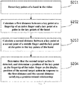
- step S201 key points of a hand in the video are detected.
- a first distance between a key point at a fingertip of an index finger and a key point at a palm in the key points of the hand is calculated.
- a second distance between a key point at a second joint of a middle finger and the key point at the palm in the key points of the hand is calculated.
- step S204 it is determined that the second target action is detected, and it is determined a position of the key point at the fingertip of the index finger as the display position of the second target action in response to the first distance and the second distance satisfying a predetermined relationship.
- any techniques for detecting key points of human hand can be used, such as the typical detection of key points of human hand based on deep learning, which trains a deep learning network using a training atlas annotated with key points of human hands, and then inputs an image to be detected into the deep learning network to output key points of a human hand in the image to be detected.
- Other techniques for detecting the key points of the human hand will not be described herein.
- a general detection method can be used to detect all key points of a human hand, or a specific network can be trained for a specific scene or a specific method can be used to detect only the key points that need to be used to improve the detection efficiency.
- a specific model can be trained to detect a key point at the fingertip of an index finger, a key point at the second joint of a middle finger, and a key point at the palm of a human hand.
- a first distance d1 between a key point at the fingertip of the index finger and a key point at the palm in the key points of the hand is calculated; and in step S203, a second distance d2 between a key point at the second joint of the middle finger and the key point of the palm in the key points of the hand is calculated.
- d1 and d2 satisfy a predetermined relationship, it is determined that the human hand has made a predetermined gesture, that is, a second target action, and in this case, the position of the key point at the fingertip of the index finger is determined as the display position of the second target action.
- the predetermined relationship is: d 1 > 1.5 ⁇ d 2 .
- the display position of the second target action it is determined whether a distance between the display position of the second target action and a position of a center point of the target object is less than a first distance threshold.
- the first distance threshold is a value of the size attribute of the target object, which can represent a distance between a center position of the target object and an edge of the target object.
- the distance between the display position of the second target action and the position of the center point of the target object is less than the first distance threshold, it means that the display position corresponding to the second target action is located within the edge range of the target object.
- the target object is a bubble
- the first trigger condition an effect of a bubble disappearing when a user pokes the bubble with an index finger can be realized.
- the display state attribute of the target object can be set to the hiding, to continue waiting for the appearance of the first target action, and re-trigger the generation process of the target object.
- the method for displaying an object in a video further comprises: a first object being presented in the target object, wherein the first object is formed by deforming a second object, the second object being an object in the video captured by the camera element.
- the second object is any object in the video.
- the second object is a human face in the video
- the deformation is scaling and large-eyed processing. After detecting a human face in the video, the human face is cut out and is subjected to large-eyed processing, so that the eyes in the face are enlarged. Then, the face upon the large-eyed processing is scaled to adapt to the size of the target object, so as to obtain a deformed face, and the deformed face is then rendered in the target object.
- the first object moves, and/or rotates, and/or changes in size following the target object.
- the present disclosure discloses a method and device for displaying an object in a video, an electronic device, and a computer-readable storage medium.
- the method for displaying an object in a video comprises: obtaining and displaying a video captured by a camera element; and displaying a generation process of a target object in the video based on a display position of a first target action in the video in response to detecting that the first target action appears in the video; wherein the generation process of the target object comprises: the target object appearing at the display position and changing from small to large.
- FIG. 4 is a schematic structural diagram of an device for displaying an object in a video provided by an embodiment of the present disclosure. As shown in FIG. 4 , the device 400 comprises: a video display module 401 and a target object display module 402.
- the video display module 401 is configured to obtain and display a video captured by a camera element.
- the target object display module 402 is configured to display a generation process of a target object in the video based on a display position of a first target action in the video in response to detecting that the first target action appears in the video; wherein the generation process of the target object comprises: the target object appearing at the display position and changing from small to large.
- the generation process of the target object specifically comprises: the target object appearing at the display position of the first target action according to a first size threshold; and a size of the target object increasing from the first size threshold until the size of the target object reaching a second size threshold; wherein the first size threshold is less than the second size threshold.
- the target object display module 402 is further configured to display a motion process of the target object in the video; wherein the motion process of the target object comprises: the target object moving, and/or the target object rotating, and/or a size of the target object changing.
- the moving of the target object comprises: the target object moving the display position along a first linear trajectory, wherein the first linear trajectory is determined by a first movement speed and a first movement direction.
- the rotating of the target object comprises: the target object rotating along a first rotation trajectory, wherein the first rotation trajectory is determined by a first rotation direction and a first angular velocity.
- the changing of the size of the target object comprises: the size of the target object changing between a third size threshold and a fourth size threshold.
- the moving of the target object further comprises: the target object switching from the first linear trajectory to a second linear trajectory to move the display position in response to the target object colliding with an edge of the video, wherein the second linear trajectory is determined by a second movement speed and a second movement direction.
- the rotating of the target object comprises: the target object switching from the first rotation trajectory to a second rotation trajectory for rotation in response to the target object colliding with an edge of the video, wherein the second rotation trajectory is determined by a second rotation direction and a second angular velocity.
- the target object display module 402 is further configured to display a disappearance process of the target object in the video in response to detecting a first trigger condition.
- the displaying of the disappearance process of the target object in the video comprises: obtaining a disappearance sequence frame of the target object; playing the disappearance sequence frame in the video; and making the target object disappear from the video when the playing of the disappearance sequence frame is finished.
- the first trigger condition is that a second target action appears in the video, wherein a display position of the second target action in the video is within a display range of the target object.
- the target object display module 402 is further configured to: detect key points of a hand in the video; calculate a first distance between a key point at a fingertip of an index finger and a key point at a palm in the key points of the hand; calculate a second distance between a key point at a second joint of a middle finger and the key point at the palm in the key points of the hand; and determine that the second target action is detected, and determine a position of the key point at the fingertip of the index finger as the display position of the second target action in response to the first distance and the second distance satisfying a predetermined relationship.
- the generation process of the target object further comprises: a first object being presented in the target object, wherein the first object is formed by deforming a second object, the second object being an object in the video captured by the camera element.
- the device shown in FIG. 4 may execute the method of the embodiments shown in FIG. 1 to FIG. 3 .
- the parts not described in detail in this embodiment reference may be made to the related description of the embodiments shown in FIG. 1 to FIG. 3 .
- For the execution process and technical effects of the technical solution reference may be made to the description of the embodiments shown in FIG. 1 to FIG. 3 , which will not be repeated herein.
- the terminal device of the embodiment of the present disclosure may comprise, but not limited to, a mobile terminal such as a mobile phone, a notebook computer, a digital broadcast receiver, a PDA (Personal Digital Assistant), a PAD (tablet computer), a PMP (Portable Multimedia Player), an on-board terminal (such as an on-board navigation terminal), and a fixed terminal such as a digital TV, a desktop computer, and the like.
- a mobile terminal such as a mobile phone, a notebook computer, a digital broadcast receiver, a PDA (Personal Digital Assistant), a PAD (tablet computer), a PMP (Portable Multimedia Player), an on-board terminal (such as an on-board navigation terminal), and a fixed terminal such as a digital TV, a desktop computer, and the like.
- PDA Personal Digital Assistant
- PAD tablet computer
- PMP Portable Multimedia Player
- an on-board terminal such as an on-board navigation terminal
- a fixed terminal such as a digital TV, a desktop computer, and
- the electronic device 500 may comprise a processing device (e.g., a central processing unit, a graphics processor) 501, which may perform various appropriate actions and processes according to a program stored in Read Only Memory (ROM) 502 or a program loaded from storage device 508 into Random Access Memory (RAM) 503. In RAM 503, various programs and data required for the operation of the electronic device 500 are also stored.
- Processing device 501, ROM 502 and RAM 503 are connected to each other through bus 504.
- Input/Output (I/O) interface 505 is also connected to bus 504.
- I/O interface 505 an input device 506 comprising, for example, a touch screen, a touch pad, a keyboard, a mouse, a camera, a microphone, an accelerometer, a gyroscope, etc.; an output device 507 comprising, for example, a liquid crystal display (LCD), a speaker, a vibrator, etc.; a storage device 508 comprising, for example, a magnetic tape, a hard disk, etc.; and a communication device 509.
- the communication device 509 enables the electronic device 500 to communicate wirelessly or by wire with other devices to exchange data.
- FIG. 5 shows the electronic device 500 with various components, it should be understood that it is not required to implement or have all of these components. Alternatively, more or fewer components can be implemented or provided.
- an embodiment of the present disclosure comprises a computer program product, which comprises a computer program carried on a non-transitory computer readable medium, the computer program containing program code for executing the method shown in the flowchart.
- the computer program may be downloaded and installed from the network through the communication device 509, or installed from the storage device 508, or from the ROM 502.
- the processing device 501 When the computer program is executed by the processing device 501, the above functions defined in the method of the embodiment of the present disclosure are performed.
- the computer-readable medium in the present disclosure may be a computer-readable signal medium or a computer-readable storage medium, or any combination of thereof.
- the computer readable storage medium can be, for example, but not limited to, an electronic, magnetic, optical, electromagnetic, infrared, or semiconductor system, apparatus, or device, or any combination of the above. More specific examples of the computer readable storage medium may comprise, but are not limited to: electrical connection with one or more wires, portable computer disk, hard disk, random access memory (RAM), read only memory (ROM), erasable programmable read only memory (EPROM or flash), fiber optics, portable compact disk Read only memory (CD-ROM), optical storage device, magnetic storage device, or any suitable combination of the foregoing.
- a computer readable storage medium can be any tangible medium that can contain or store a program, wherein the program can be used by or in connection with an instruction execution system, apparatus or device.
- a computer readable signal medium may comprise a data signal that is propagated in the baseband or as part of a carrier, carrying computer readable program code. Such propagated data signals can take a variety of forms comprising, but not limited to, electromagnetic signals, optical signals, or any suitable combination of the foregoing.
- the computer readable signal medium can also be any computer readable medium other than a computer readable storage medium, which can transmit, propagate, or transport a program for use by or in connection with the instruction execution system, apparatus, or device.
- Program code embodied on a computer readable medium can be transmitted by any suitable medium, comprising but not limited to wire, optic cable, RF (radio frequency), etc., or any suitable combination of the foregoing.
- a client and a server can communicate using any currently known or future developed network protocol such as HTTP (HyperText Transfer Protocol), and can be interconnected by any form or medium of digital data communication, e.g., a communication network.
- HTTP HyperText Transfer Protocol
- Examples of communication networks comprise a local area network ("LAN”) and a wide area network (“WAN”), the Internet, and end-to-end networks (for example, ad hoc end-to-end networks), as well as any currently known or future developed networks.
- the above computer-readable medium may be comprised in the electronic device described above; or it may exist alone without being assembled into the electronic device.
- the computer-readable medium carries one or more programs that cause, when executed by the electronic device, the electronic device to obtain and display a video captured by a camera element; and display a generation process of a target object in the video based on a display position of a first target action in the video in response to detecting that the first target action appears in the video; wherein the generation process of the target object comprises: the target object appearing at the display position and changing from small to large.
- the computer program code for executing operations of the present disclosure may be written in one or more program design languages or combinations thereof, the program design languages comprising, but being not limited to, object-oriented program design languages, such as Java, Smalltalk, C++, etc., as well as conventional procedural program design languages, such as "C" program design language or similar program design language.
- a program code may be completely or partly executed on a user computer, or executed as an independent software package, partly executed on the user computer and partly executed on a remote computer, or completely executed on a remote computer or server.
- the remote computer may be connected to the user computer through various kinds of networks, comprising local area network (LAN) or wide area network (WAN), or connected to external computer (for example using an internet service provider via Internet).
- LAN local area network
- WAN wide area network
- Internet for example using an internet service provider via Internet
- each block in the flowchart or block diagrams may represent a module, segment, or portion of code, which comprises one or more executable instructions for implementing the specified logical functions.
- the functions noted in the block may occur out of the order noted in the figures. For example, two blocks shown in succession may be executed substantially in parallel, or the blocks may sometimes be executed in the reverse order, depending upon the functionality involved.
- the units involved in the embodiments described in the present disclosure can be implemented in software or hardware. Wherein, the names of the units do not constitute a limitation on the units themselves under certain circumstances.
- exemplary types of hardware logic components comprise: Field Programmable Gate Array (FPGA), Application Specific Integrated Circuit (ASIC), Application Specific Standard Product (ASSP), System on Chip (SOC), Complex Programmable Logic Device (CPLD), etc.
- FPGA Field Programmable Gate Array
- ASIC Application Specific Integrated Circuit
- ASSP Application Specific Standard Product
- SOC System on Chip
- CPLD Complex Programmable Logic Device
- a machine-readable medium may be a tangible medium, which may contain or store a program for use by or in connection with an instruction execution system, apparatus, or device.
- the machine-readable medium may be a machine-readable signal medium or a machine-readable storage medium.
- the machine-readable medium may comprise, but is not limited to, an electronic, magnetic, optical, electromagnetic, infrared, or semiconductor system, apparatus, or device, or any suitable combination of thereof.
- machine-readable storage medium may comprise electrical connection with one or more wires, portable computer disk, hard disk, random access memory (RAM), read only memory (ROM), erasable programmable read only memory (EPROM or flash memory), fiber optics, portable compact disk read only memory (CD-ROM), optical storage device, magnetic storage device, or any suitable combination of the foregoing.
- RAM random access memory
- ROM read only memory
- EPROM or flash memory erasable programmable read only memory
- CD-ROM compact disk read only memory
- optical storage device magnetic storage device, or any suitable combination of the foregoing.
- An embodiment of the present disclosure further provides a computer program product, comprising a computer program, which, when executed, is used to implement the method of displaying an object in a video provided by the embodiment of the present disclosure.
- a method for displaying an object in a video comprising: obtaining and displaying a video captured by a camera element; and displaying a generation process of a target object in the video based on a display position of a first target action in the video in response to detecting that the first target action appears in the video; wherein the generation process of the target object comprises: the target object appearing at the display position and changing from small to large.
- the generation process of the target object comprises: the target object appearing at the display position of the first target action according to a first size threshold; and a size of the target object increasing from the first size threshold until the size of the target object reaching a second size threshold; wherein the first size threshold is less than the second size threshold.
- the method further comprises: displaying a motion process of the target object in the video; wherein the motion process of the target object comprises: the target object moving, and/or the target object rotating, and/or a size of the target object changing.
- the moving of the target object comprises: the target object moving the display position along a first linear trajectory, wherein the first linear trajectory is determined by a first movement speed and a first movement direction.
- the rotating of the target object comprises: the target object rotating along a first rotation trajectory, wherein the first rotation trajectory is determined by a first rotation direction and a first angular velocity.
- the changing of the size of the target object comprises: the size of the target object changing between a third size threshold and a fourth size threshold.
- the moving of the target object further comprises: the target object switching from the first linear trajectory to a second linear trajectory to move the display position in response to the target object colliding with an edge of the video, wherein the second linear trajectory is determined by a second movement speed and a second movement direction.
- the rotating of the target object comprises: the target object switching from the first rotation trajectory to a second rotation trajectory for rotation in response to the target object colliding with an edge of the video, wherein the second rotation trajectory is determined by a second rotation direction and a second angular velocity.
- the method further comprises: displaying a disappearance process of the target object in the video in response to detecting a first trigger condition.
- the displaying of the disappearance process of the target object in the video comprises: obtaining a disappearance sequence frame of the target object; playing the disappearance sequence frame in the video; and making the target object disappear from the video when the playing of the disappearance sequence frame is finished.
- the first trigger condition is that a second target action appears in the video, wherein a display position of the second target action in the video is within a display range of the target object.
- the method for displaying an object in a video further comprises: detecting key points of a hand in the video; calculating a first distance between a key point at a fingertip of an index finger and a key point at a palm in the key points of the hand; calculating a second distance between a key point at a second joint of a middle finger and the key point at the palm in the key points of the hand; and determining that the second target action is detected, and determining a position of the key point at the fingertip of the index finger as the display position of the second target action in response to the first distance and the second distance satisfying a predetermined relationship.
- a first object is presented in the target object, wherein the first object is formed by deforming a second object, the second object being an object in the video captured by the camera element.
- an device for displaying an object in a video comprising: a video display module configured to obtain and display a video captured by a camera element; and a target object display module configured to display a generation process of a target object in the video based on a display position of a first target action in the video in response to detecting that the first target action appears in the video; wherein the generation process of the target object comprises: the target object appearing at the display position and changing from small to large.
- the generation process of the target object comprises: the target object appearing at the display position of the first target action according to a first size threshold; and a size of the target object increasing from the first size threshold until the size of the target object reaching a second size threshold; wherein the first size threshold is less than the second size threshold.
- the target object display module is further configured to display a motion process of the target object in the video; wherein the motion process of the target object comprises: the target object moving, and/or the target object rotating, and/or a size of the target object changing.
- the moving of the target object comprises: the target object moving the display position along a first linear trajectory, wherein the first linear trajectory is determined by a first movement speed and a first movement direction.
- the rotating of the target object comprises: the target object rotating along a first rotation trajectory, wherein the first rotation trajectory is determined by a first rotation direction and a first angular velocity.
- the changing of the size of the target object comprises: the size of the target object changing between a third size threshold and a fourth size threshold.
- the moving of the target object further comprises: the target object switching from the first linear trajectory to a second linear trajectory to move the display position in response to the target object colliding with an edge of the video, wherein the second linear trajectory is determined by a second movement speed and a second movement direction.
- the rotating of the target object comprises: the target object switching from the first rotation trajectory to a second rotation trajectory for rotation in response to the target object colliding with an edge of the video, wherein the second rotation trajectory is determined by a second rotation direction and a second angular velocity.
- the target object display module is further configured to display a disappearance process of the target object in the video in response to detecting a first trigger condition.
- the displaying of the disappearance process of the target object in the video comprises: obtaining a disappearance sequence frame of the target object; playing the disappearance sequence frame in the video; and making the target object disappear from the video when the playing of the disappearance sequence frame is finished.
- the first trigger condition is that a second target action appears in the video, wherein a display position of the second target action in the video is within a display range of the target object.
- the target object display module is further configured to: detect key points of a hand in the video; calculate a first distance between a key point at a fingertip of an index finger and a key point at a palm in the key points of the hand; calculate a second distance between a key point at a second joint of a middle finger and the key point at the palm in the key points of the hand; and determine that the second target action is detected, and determine a position of the key point at the fingertip of the index finger as the display position of the second target action in response to the first distance and the second distance satisfying a predetermined relationship.
- the generation process of the target object further comprises: a first object being presented in the target object, wherein the first object is formed by deforming a second object, the second object being an object in the video captured by the camera element.
- an electronic device comprising: at least one processor; and a memory coupled in communication with the at least one processor; wherein the memory stores instructions executable by the at least one processor, the instructions when executed by the at least one processor causing the at least one processor to perform any aforementioned method for displaying an object in a video.
- a non-transitory computer-readable storage medium stores computer instructions used to cause a computer to execute any aforementioned method for displaying an object in a video.
- a computer program product comprising a computer program, which, when executed, is used to implement the method of displaying an object in a video provided by the embodiment of the present disclosure.
Landscapes
- Engineering & Computer Science (AREA)
- Multimedia (AREA)
- Theoretical Computer Science (AREA)
- Signal Processing (AREA)
- Physics & Mathematics (AREA)
- General Physics & Mathematics (AREA)
- Computer Vision & Pattern Recognition (AREA)
- Human Computer Interaction (AREA)
- Health & Medical Sciences (AREA)
- General Health & Medical Sciences (AREA)
- Social Psychology (AREA)
- Psychiatry (AREA)
- General Engineering & Computer Science (AREA)
- Evolutionary Computation (AREA)
- Databases & Information Systems (AREA)
- Computing Systems (AREA)
- Artificial Intelligence (AREA)
- Medical Informatics (AREA)
- Software Systems (AREA)
- Computer Graphics (AREA)
- Processing Or Creating Images (AREA)
- User Interface Of Digital Computer (AREA)
- Two-Way Televisions, Distribution Of Moving Picture Or The Like (AREA)
- Image Analysis (AREA)
- Studio Devices (AREA)
- Studio Circuits (AREA)
- Controls And Circuits For Display Device (AREA)
Abstract
Description
- The present disclosure claims the priority to
China Patent Application No.201911196331.6 filed on November 29, 2019 - The present disclosure relates to the field of image processing, and in particular, to a method and a device for displaying an object in a video, an electronic device, and a computer-readable storage medium.
- With the development of computer networks and the popularization of smart phones, ordinary users may no longer be satisfied with expressing their emotions only with monotonous pictures and words. Video is deeply loved by users because of its richer and more diverse content and forms and the intuitive feeling it brings, and it is gradually becoming popular. It has gradually become a trend for ordinary users to create original videos. However, on the other hand, original selfie videos are usually presented in a bland form. At the same time, we can see that the use of video special effects in film and television works is becoming more and more abundant, and the content expression forms are also more diversified. It can be said that video special effects are the support and guarantee of a successful film and television work.
- However, current video special effects generally have fixed display effects and are not flexible enough. For example, in general, a special effect can only be displayed at a preset position in a video, or the display of a special effect can only move with an object in the video. It is impossible for a special effect to make some changes or movements by itself.
- This summary is provided for a concise introduction of the inventive concept of the present application, which will be described in detail in the detailed description below. This summary is not intended to identify critical features or essential features of the claimed technical solution, nor is it intended to be used to limit the scope of the claimed technical solution.
- In a first aspect, an embodiment of the present disclosure provides a method for displaying an object in a video, comprising: obtaining and displaying a video captured by a camera element; and displaying a generation process of a target object in the video based on a display position of a first target action in the video in response to detecting that the first target action appears in the video; wherein the generation process of the target object comprises: the target object appearing at the display position and changing from small to large.
- In a second aspect, an embodiment of the present disclosure provides an device for displaying an object in a video, comprising: a video display module configured to obtain and display a video captured by a camera element; and a target object display module configured to display a generation process of a target object in the video based on a display position of a first target action in the video in response to detecting that the first target action appears in the video; wherein the generation process of the target object comprises: the target object appearing at the display position and changing from small to large.
- In a third aspect, an embodiment of the present disclosure provides an electronic device, comprising: at least one processor; and a memory coupled in communication with the at least one processor; wherein the memory stores instructions executable by the at least one processor, the instructions when executed by the at least one processor causing the at least one processor to perform the method of displaying an object in a video according to any one of the embodiments in the foregoing first aspect.
- In a fourth aspect, an embodiment of the present disclosure provides a non-transitory computer-readable storage medium, wherein the non-transitory computer-readable storage medium stores computer instructions used to cause a computer to execute the method of displaying an object in a video according to any one of the embodiments in the foregoing first aspect.
- In a fifth aspect, an embodiment of the present disclosure provides a computer program product, comprising a computer program, which, when executed, is used to implement the method of displaying an object in a video provided by the embodiment of the present disclosure.
- The present disclosure discloses a method and a device for displaying an object in a video, an electronic device, and a computer-readable storage medium. The method for displaying an object in a video comprises: obtaining and displaying a video captured by a camera element; and displaying a generation process of a target object in the video based on a display position of a first target action in the video in response to detecting that the first target action appears in the video; wherein the generation process of the target object comprises: the target object appearing at the display position and changing from small to large. The above method solves the technical problem in the prior art that the display effect of the special effect is fixed and the special effect cannot perform some changes or movements, thereby making the display effect of the special effect more flexible.
- The above and other features, advantages, and aspects of the embodiments of the present disclosure will become more apparent from the following embodiments with reference to the drawings. Throughout the drawings, the same or similar reference signs indicate the same or similar elements. It should be understood that the drawings are schematic and the components and elements are not necessarily drawn to scale.
-
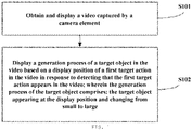
FIG. 1 is a flowchart of an embodiment of a method for displaying an object in a video provided by the present disclosure; -
FIG. 2 is a flowchart of a specific example of determining a display position of a second target action in the embodiment of the method for displaying an object in a video provided by the present disclosure; -
FIG. 3 is a schematic diagram of a distance d1 and a distance d2 in the embodiment of the method for displaying an object in a video provided by the present disclosure; -
FIG. 4 is a schematic structural diagram of an device for displaying an object in a video provided by an embodiment of the present disclosure; -
FIG. 5 is a schematic structural diagram of an electronic device provided according to an embodiment of the present disclosure. - Exemplary embodiments of the present disclosure will now be described in detail with reference to the accompanying drawings. Although some embodiments of the present disclosure are shown, it should be understood that the present disclosure can be implemented in various forms, and should not be construed as being limited to the embodiments set forth herein. On the contrary, these embodiments are provided for a more thorough and complete understanding of the present disclosure. It should be understood that the drawings and embodiments of the present disclosure are only used for exemplary purposes, and are not used to limit the scope of protection of the present disclosure.
- It should be understood that the various steps described in the methods of the embodiments of the present disclosure may be executed in a different order, and/or executed in parallel. In addition, the method embodiments may comprise additional steps and/or some of the illustrated steps may be omitted. The scope of this disclosure is not limited in this regard.
- The term "comprising" and its variants as used herein is an open-ended mode expression, that is, "comprising but not limited to". The term "based on" means "based at least in part on". The term "one embodiment" means "at least one embodiment"; the term "another embodiment" means "at least one additional embodiment"; and the term "some embodiments" means "at least some embodiments". Related definitions of other terms will be given in the following description.
- It should be noted that the concepts of "first" , "second" or the like mentioned in the present disclosure are only used to distinguish different devices, modules or units, and are not used to limit the order of functions performed by these devices, modules or units, or interdependence therebetween.
- It should be noted that the modifications of "a" and "a plurality of" mentioned in the present disclosure are illustrative and not restrictive, and those skilled in the art should understand that unless clearly indicated in the context, they should be understood as "one or more".
- The names of messages or information exchanged between multiple devices in the embodiments of the present disclosure are only used for illustrative purposes, and are not used to limit the scope of these messages or information.
-
FIG. 1 is a flowchart of a method for displaying an object in a video provided by an embodiment of the present disclosure. The method for displaying an object in a video provided by the embodiment can be performed by an device for displaying an object in a video. The device for displaying an object in a video may be implemented as software, or as a combination of software and hardware. The device for displaying an object in a video may be integrated into a certain device in a system for displaying an object in a video, such as, a server that displays an object in a video or a terminal device that displays an object in a video. As shown inFIG. 1 , the method comprises the following steps: - At step S101, a video captured by a camera element is obtained and displayed.
- In the present disclosure, the camera element refers to various image sensing devices that can capture video. Exemplary camera elements are video cameras, web cameras, cameras, and so on. In the embodiment, the camera element may be a camera on a terminal device, such as a front or rear camera on a mobile phone, and the video collected by the camera is displayed on a display screen of the mobile phone. In the step, a video captured by the camera element is acquired and displayed as a display background of a target object in the present disclosure.
- At step S102, a generation process of a target object is displayed in the video based on a display position of a first target action in the video in response to detecting that the first target action appears in the video; wherein the generation process of the target object comprises: the target object appearing at the display position and changing from small to large.
- In the present disclosure, a first target action can be preset as a trigger condition, and when it is detected that the first target action appears in the video, the displaying of a generation process of a target object is triggered.
- Optionally, the detecting of that the first target action appears in the video comprises: identifying a feature point of a target object in the video; determining a position of a specific feature point of the feature point; and determining that the first target action appears in the video in response to the position of the specific feature point conforming an expected position. Exemplarily, the first target action is pouting, the specific feature point is a feature point of a mouth, and when it is determined that a distance between the feature point of the mouth and a center point of the mouth is less than a preset value, it is determined that a pouting action performed by the mouth of the human face.
- Optionally, the detecting of that the first target action appears in the video comprises: inputting the video into a pre-trained convolutional neural network, wherein the convolutional neural network is configured to identify the first target action; and determining that the first target action appears in the video in response to an output value of the convolutional neural network being greater than a judgment threshold. Exemplarily, if the first target action is pouting, various video frames comprising pouting actions can be input into the convolutional neural network to calculate errors for the convolutional neural network using a loss function, the errors are fed back to the convolutional neural network to adjust parameters of the convolutional neural network, and a convolutional neural network that can be used to identify a pouting action can be obtained after several times of training. Then, a action in the video can be determined by inputting video frames collected by the camera element into the convolutional neural network.
- After the first target action is identified, the target object appearing at the display position of the first target action and changes from small to large. The display position of the first target action is a center position of a first object that makes the first target action. In an example, the target object is a mouth, and its display position is set to a center position of the mouth. In another example, the target object is an eye, and its display position is set to a center position of the eye. The target object is an object in a special effect, which is rendered at the display position in a preset manner. In the embodiment, the target object is rendered at the display position and gradually increases from small to large.
- Optionally, the generation process of the target object comprises: the target object appearing at the display position of the first target action according to a first size threshold; and a size of the target object increasing from the first size threshold until the size of the target object reaching a second size threshold; wherein the first size threshold is less than the second size threshold. In an embodiment, the target object comprises a display state attribute, and the target object is rendered in the video in different states by setting different display state attribute values. Exemplarily, the display state attribute value may comprise: hiding, enlarging, moving, and disappearing. Before detecting that the first target action appears in the video, the display state attribute value is set to the hiding, and the target object will not displayed in this case; in response to detecting the first target action, the display state attribute value of the target object is set to the enlarging to display a generation process of the target object in the video. Specifically, the target object further comprises a size attribute, and a value of the size attribute determines a display size of the target object in the video. In the embodiment, two size attribute values of the target object, namely, a first size threshold and a second size threshold are obtained, respectively. The first size threshold is an initial size attribute value of the displayed target object, and the second size threshold is a maximum value of the size attribute of of the target object in its enlarging state. After the first size threshold and the second size threshold are obtained, the size attribute value of the target object is changed from the first size threshold to the second size threshold in multiple frames of the video. Exemplarily, changing the size attribute value of the target object from the first size threshold to the second size threshold may comprise, starting from the first size threshold, adding a fixed increment each time, wherein the increased size attribute value is used as the size attribute value of the target object, and then rendering the target object according to the increased size attribute value in a next image fame until the size attribute value reaches the second size threshold. Exemplarily, if the target object is a bubble, when a first target action is detected, a bubble is rendered at the display position of the first target action. A first size threshold of the bubble is 0, the second size threshold of the bubble is 200 pixels, and a process of rendering a bubble with a radius that changes from 0 to 200 pixels, that is, a process of displaying a bubble that increases from small to large is displayed in the video.
- Optionally, the first size threshold and the second size threshold of the size attribute of the target object are preset values, which may be preset fixed values or values calculated according to a predetermined condition. If the target object is a circle object, the initial value of its radius can be set to a fixed length of 100 pixels; or its initial value can be set to 1/5 of the length of the video, and so on.
- Optionally, the first size threshold and the second size threshold of the size attribute of the target object are obtained by random calculation during acquisition, and it is only necessary to ensure that the second size threshold is greater than the first size threshold when the second size threshold is randomly acquired. In this way, when a plurality of the target objects are displayed, the effect of a plurality of target objects presented in different sizes can be achieved.
- Optionally, in the step, the generation process of the target object comprises: obtaining a display position of the target object; obtaining an enlargement function, wherein the enlargement function represents a corresponding relationship between time and the size attribute value; determining a size attribute value of the target object at a current time according to the enlargement function; and rendering the target object in the video according to the display position of the target object and the size attribute value. Optionally, the enlargement function is a corresponding relationship between the time and the size attribute value, and is used to control an enlargement speed of the target object. For example, when the state attribute value of the target object is set to the enlarging, the size attribute value of the target object is increased from the first size threshold to the second size threshold within N seconds. Exemplarily, if the first size threshold is 0 and the second size threshold is M, the target object is controlled to be enlarged by M/N length units per second, so that after N seconds since that the state attribute of the target object is set to the enlarging, the size attribute value of the target object is enlarged to M. According to the display position of the target object and the enlargement function, the target object is rendered in the video image, and the target object is displayed with the effect of gradually enlarging from small to large.
- It can be understood that the specific implementation of the above enlargement function is only an example, and does not constitute a limitation of the present disclosure. In fact, various enlargement methods can be used to achieve different effects.
- In an embodiment, after the displaying of the generation process of the target object in the video, the method further comprises: step S103, displaying a motion process of the target object in the video; wherein the motion process of the target object comprises: the target object moving, and/or the target object rotating, and/or a size of the target object changing. In the embodiment, the state attribute value of the target object is set to the moving, and in this case, the target object moves according to a preset motion attribute value.
- The moving of the target object comprises: the target object moving the display position along a first linear trajectory, wherein the first linear trajectory is determined by a first movement speed and a first movement direction. In the embodiment, the motion attribute of the target object comprises a movement direction and a movement speed. The display position of the target object in each frame of the video can be calculated according to the display position, movement direction and movement speed of the target object. Optionally, the first movement direction is a direction angle, the direction angle being an comprised angle between the movement direction and a horizontal axis. The comprised angle can take any value between 0° and 360° . The first movement speed represents a distance that the target object moves in a unit time, from which the first linear trajectory can be calculated. The first linear trajectory consists of a plurality of display positions, each display position corresponding to a display position of the target object at a certain time. Then, a corresponding display position is acquired according to a current time, and the target object is rendered at the display position. Optionally, a second display position of the target object at a next time can also be calculated according to a first display position, the first movement speed and the first movement direction of the target object at the current time, and the target object is rendered at the second display position when the next time arrives. The display position is calculated in multiple frames and the target object is rendered so that the target object exhibits a state of movement.
- The rotating of the target object comprises:: the target object rotating along a first rotation trajectory, wherein the first rotation trajectory is determined by a first rotation direction and a first angular velocity. In the embodiment, the rotation of the target object is the self-rotation of the target object on a display plane of the video, and the motion attribute of the target object comprises a rotation direction and an angular velocity. A rotation angle of the target object in each frame of the video can be calculated according to an initial rotation angle, a rotation direction and an angular velocity of the target object. The rotation direction comprises clockwise rotation and counterclockwise rotation, and the angular velocity is the rotation speed of the target object, wherein the angular velocity represents a rotation angle of the target object per unit time. After the first rotation direction and the first angular velocity of the target object are determined, the first rotation trajectory can be calculated according to an initial rotation angle of the target object, and the first rotation trajectory is composed of rotation angles of the target object at various times. Then, a corresponding rotation angle is acquired according to a current time, and the target object is rotated and rendered at the display position corresponding to the current time according to the rotation angle. Optionally, a second rotation angle of the target object at a next time can also be calculated according to the first rotation angle, the first rotation direction and the first angular velocity of the target object at the current time, and the target object is rendered at the second rotation angle when the next time arrives. The rotation angle is calculated continuously in multiple frames, and the target object is rendered so that the target object exhibits a state of rotation.
- The changing of the size of the target object comprises: the size of the target object changing between a third size threshold and a fourth size threshold. In the embodiment, the size attribute value of the target object is set to change between the third size threshold and the fourth size threshold. Exemplarily, the change is that the size attribute value of the target object changes from a small size to a large size and/or from a large size to a small size between the third size threshold and the fourth size threshold. Optionally, the change occurs at a preset fixed speed. For example, the size attribute value of the target object gradually changes from the third size threshold to the fourth size threshold at a fixed speed, and then gradually changes from the fourth size threshold to the third size threshold at a fixed speed. Optionally, the change is controlled by a size change control function, wherein the size change control function is a function with time as a variable, so that a size attribute value of the target object at each time can be calculated based on the size change control function. Exemplarily, the size change control function is:

- In an embodiment, the moving of the target object further comprises: the target object switching from the first linear trajectory to a second linear trajectory to move the display position in response to the target object colliding with an edge of the video, wherein the second linear trajectory is determined by a second movement speed and a second movement direction. The rotating of the target object comprises: the target object switching from the first rotation trajectory to a second rotation trajectory for rotation in response to the target object colliding with an edge of the video, wherein the second rotation trajectory is determined by a second rotation direction and a second angular velocity. Optionally, the target object colliding with an edge of the video comprises: obtaining an edge position of the video; and determining that the target object collides with an edge of the video in response to an edge position of the target object being coincident with the edge position of the video. Exemplarily, the edges of the video are set as four straight lines represented by X=0, Y=0, X=W, Y=H, respectively. Coordinates of an edge point of the target object are calculated. If X=0 or Y=0 or X=W or Y=H in the coordinates (X, Y) of the edge point of the target object, it is determined that an edge position of the target object coincides with an edge position of the video, that is, the target object collides with an edge of the video. After the collision occurs, a new motion attribute of the target object is generated, wherein the new motion attribute comprises a second movement speed, a second movement direction, and/or a second rotation direction and a second angular velocity. Then, a display position of the target object is determined according to a second movement trajectory determined by the second movement speed and the second movement direction, and/or a rotation angle of the target object is determined according to a second rotation trajectory determined by the second rotation direction and the second angular velocity. After a collision occurs, an initial display position of the target object is a display position of the target object when the collision occurs, and the initial rotation angle of the target object is a rotation angle of the target object when the collision occurs.
- In an embodiment, the method for displaying an object in a video further comprises: step S104, displaying a disappearance process of the target object in the video in response to detecting a first trigger condition. The step S104 may be executed after the step S102 or after the step S103, or may be executed in parallel with the execution of step S102. That is to say, as long as the target object has been generated, regardless of in the generation process or in the subsequent motion process, when the first trigger condition is detected, a disappearance process of the target object will be displayed in the video. In the embodiment, the display state attribute value of the target object is set to the disappearing. Optionally, the displaying of the disappearance process of the target object in the video comprises: obtaining a disappearance sequence frame of the target object; playing the disappearance sequence frame in the video; and making the target object disappear from the video when the playing of the disappearance sequence frame is finished. The disappearance sequence frame of the target object is an animation. For example, the animation shows a disappearance procedure of the target object, from a complete target object to an broken target object until complete disappearance of the target object. After the disappearance sequence frame is obtained, it is played back in the video, and after the playback of the disappearance sequence frame is completed, the target object disappears from the video. Specifically, a transparency of the target object can be controlled according to a playback time length of the sequence frames. The transparency of the target object gradually increases with the playback of the disappearance sequence frame until the target object becomes completely transparent when the playing of the disappearance sequence frame is finished.
- Optionally, the first trigger condition is that a time length that the target object has been displayed in the video exceeds a preset time threshold. Optionally, the display time length here is a length of time elapsed after the value of the display state attribute of the target object is set to the enlarging. Optionally, the display time length here is a length of time elapsed after the value of the display state attribute of the target object is set to the moving.
- Optionally, the first trigger condition is that a second target action appears in the video, wherein a display position of the second target action in the video is within a display range of the target object. Exemplarily, the second target action is to stretch out an index finger, and the display position of the second target action is a position of a fingertip of the index finger. When the position of the fingertip of the index finger is within the display range of the target object, it means that the first trigger condition is detected. Further, the determining of a display position of the second target action comprises the following steps.
- At step S201, key points of a hand in the video are detected.
- At step S202, a first distance between a key point at a fingertip of an index finger and a key point at a palm in the key points of the hand is calculated.
- At step S203, a second distance between a key point at a second joint of a middle finger and the key point at the palm in the key points of the hand is calculated.
- At step S204, it is determined that the second target action is detected, and it is determined a position of the key point at the fingertip of the index finger as the display position of the second target action in response to the first distance and the second distance satisfying a predetermined relationship.
- Optionally, in the step S201, any techniques for detecting key points of human hand can be used, such as the typical detection of key points of human hand based on deep learning, which trains a deep learning network using a training atlas annotated with key points of human hands, and then inputs an image to be detected into the deep learning network to output key points of a human hand in the image to be detected. Other techniques for detecting the key points of the human hand will not be described herein. Optionally, in the step, a general detection method can be used to detect all key points of a human hand, or a specific network can be trained for a specific scene or a specific method can be used to detect only the key points that need to be used to improve the detection efficiency. Optionally, in the embodiment, a specific model can be trained to detect a key point at the fingertip of an index finger, a key point at the second joint of a middle finger, and a key point at the palm of a human hand. As shown in
FIG. 3 , in step S202, a first distance d1 between a key point at the fingertip of the index finger and a key point at the palm in the key points of the hand is calculated; and in step S203, a second distance d2 between a key point at the second joint of the middle finger and the key point of the palm in the key points of the hand is calculated. If d1 and d2 satisfy a predetermined relationship, it is determined that the human hand has made a predetermined gesture, that is, a second target action, and in this case, the position of the key point at the fingertip of the index finger is determined as the display position of the second target action. Optionally, the predetermined relationship is:
- That is to say, if d1 is greater than 1.5 times d2, it is determined that the human hand makes an action of stretching out the index finger, and in this case, the position of the key point at the fingertip of the index finger is obtained.
- Optionally, after determining the display position of the second target action, it is determined whether a distance between the display position of the second target action and a position of a center point of the target object is less than a first distance threshold. The first distance threshold is a value of the size attribute of the target object, which can represent a distance between a center position of the target object and an edge of the target object. When the distance between the display position of the second target action and the position of the center point of the target object is less than the first distance threshold, it means that the display position corresponding to the second target action is located within the edge range of the target object. Exemplarily, if the target object is a bubble, with the first trigger condition, an effect of a bubble disappearing when a user pokes the bubble with an index finger can be realized.
- Optionally, after the target object disappears completely, the display state attribute of the target object can be set to the hiding, to continue waiting for the appearance of the first target action, and re-trigger the generation process of the target object.
- Optionally, the method for displaying an object in a video further comprises: a first object being presented in the target object, wherein the first object is formed by deforming a second object, the second object being an object in the video captured by the camera element. The second object is any object in the video. Exemplarily, the second object is a human face in the video, and the deformation is scaling and large-eyed processing. After detecting a human face in the video, the human face is cut out and is subjected to large-eyed processing, so that the eyes in the face are enlarged. Then, the face upon the large-eyed processing is scaled to adapt to the size of the target object, so as to obtain a deformed face, and the deformed face is then rendered in the target object. After presenting the first object within the target object, the first object moves, and/or rotates, and/or changes in size following the target object.
- The present disclosure discloses a method and device for displaying an object in a video, an electronic device, and a computer-readable storage medium. The method for displaying an object in a video comprises: obtaining and displaying a video captured by a camera element; and displaying a generation process of a target object in the video based on a display position of a first target action in the video in response to detecting that the first target action appears in the video; wherein the generation process of the target object comprises: the target object appearing at the display position and changing from small to large. The above method solves the technical problem in the prior art that the display effect of the special effect is fixed and the special effect cannot perform some changes or movements, thereby making the display effect of the special effect more flexible.
- In the above description, although the steps of the above method embodiment are described in the order described above, it should be clear to those skilled in the art that the steps of the embodiment of the present disclosure are not necessarily executed in the above order, and may also be performed in other orders such as reverse order, parallel, crossover, etc. Moreover, on the basis of the above steps, those skilled in the art can add other steps, and these apparent modifications or equivalent alternatives should also be comprised within the protection scope of the present disclosure, which will not be repeated herein.
-
FIG. 4 is a schematic structural diagram of an device for displaying an object in a video provided by an embodiment of the present disclosure. As shown inFIG. 4 , thedevice 400 comprises: avideo display module 401 and a targetobject display module 402. - The
video display module 401 is configured to obtain and display a video captured by a camera element. - The target
object display module 402 is configured to display a generation process of a target object in the video based on a display position of a first target action in the video in response to detecting that the first target action appears in the video; wherein the generation process of the target object comprises: the target object appearing at the display position and changing from small to large. - Further, the generation process of the target object specifically comprises: the target object appearing at the display position of the first target action according to a first size threshold; and a size of the target object increasing from the first size threshold until the size of the target object reaching a second size threshold; wherein the first size threshold is less than the second size threshold.
- Further, after the displaying of the generation process of the target object in the video, the target
object display module 402 is further configured to display a motion process of the target object in the video; wherein the motion process of the target object comprises: the target object moving, and/or the target object rotating, and/or a size of the target object changing. - Further, the moving of the target object comprises: the target object moving the display position along a first linear trajectory, wherein the first linear trajectory is determined by a first movement speed and a first movement direction.
- Further, the rotating of the target object comprises: the target object rotating along a first rotation trajectory, wherein the first rotation trajectory is determined by a first rotation direction and a first angular velocity.
- Further, the changing of the size of the target object comprises: the size of the target object changing between a third size threshold and a fourth size threshold.
- Further, the moving of the target object further comprises: the target object switching from the first linear trajectory to a second linear trajectory to move the display position in response to the target object colliding with an edge of the video, wherein the second linear trajectory is determined by a second movement speed and a second movement direction.
- Further, the rotating of the target object comprises: the target object switching from the first rotation trajectory to a second rotation trajectory for rotation in response to the target object colliding with an edge of the video, wherein the second rotation trajectory is determined by a second rotation direction and a second angular velocity.
- Further, the target
object display module 402 is further configured to display a disappearance process of the target object in the video in response to detecting a first trigger condition. - Further, the displaying of the disappearance process of the target object in the video comprises: obtaining a disappearance sequence frame of the target object; playing the disappearance sequence frame in the video; and making the target object disappear from the video when the playing of the disappearance sequence frame is finished.
- Further, the first trigger condition is that a second target action appears in the video, wherein a display position of the second target action in the video is within a display range of the target object.
- Further, the target
object display module 402 is further configured to: detect key points of a hand in the video; calculate a first distance between a key point at a fingertip of an index finger and a key point at a palm in the key points of the hand; calculate a second distance between a key point at a second joint of a middle finger and the key point at the palm in the key points of the hand; and determine that the second target action is detected, and determine a position of the key point at the fingertip of the index finger as the display position of the second target action in response to the first distance and the second distance satisfying a predetermined relationship. - Further, the generation process of the target object further comprises: a first object being presented in the target object, wherein the first object is formed by deforming a second object, the second object being an object in the video captured by the camera element.
- The device shown in
FIG. 4 may execute the method of the embodiments shown inFIG. 1 to FIG. 3 . For the parts not described in detail in this embodiment, reference may be made to the related description of the embodiments shown inFIG. 1 to FIG. 3 . For the execution process and technical effects of the technical solution, reference may be made to the description of the embodiments shown inFIG. 1 to FIG. 3 , which will not be repeated herein. - Referring now to
FIG. 5 , a structural diagram of an electronic device (e.g., a terminal device or server shown inFIG. 1 ) 500 suitable for implementing an embodiment of the present disclosure is shown. The terminal device of the embodiment of the present disclosure may comprise, but not limited to, a mobile terminal such as a mobile phone, a notebook computer, a digital broadcast receiver, a PDA (Personal Digital Assistant), a PAD (tablet computer), a PMP (Portable Multimedia Player), an on-board terminal (such as an on-board navigation terminal), and a fixed terminal such as a digital TV, a desktop computer, and the like. The electronic device shown inFIG. 5 is merely an example and should not impose any limitation on the function and scope of the embodiment of the present disclosure. - As shown in
FIG. 5 , the electronic device 500 may comprise a processing device (e.g., a central processing unit, a graphics processor) 501, which may perform various appropriate actions and processes according to a program stored in Read Only Memory (ROM) 502 or a program loaded fromstorage device 508 into Random Access Memory (RAM) 503. InRAM 503, various programs and data required for the operation of the electronic device 500 are also stored.Processing device 501,ROM 502 andRAM 503 are connected to each other throughbus 504. Input/Output (I/O)interface 505 is also connected tobus 504. - Generally, the following devices can be connected to I/O interface 505: an
input device 506 comprising, for example, a touch screen, a touch pad, a keyboard, a mouse, a camera, a microphone, an accelerometer, a gyroscope, etc.; anoutput device 507 comprising, for example, a liquid crystal display (LCD), a speaker, a vibrator, etc.; astorage device 508 comprising, for example, a magnetic tape, a hard disk, etc.; and acommunication device 509. Thecommunication device 509 enables the electronic device 500 to communicate wirelessly or by wire with other devices to exchange data. AlthoughFIG. 5 shows the electronic device 500 with various components, it should be understood that it is not required to implement or have all of these components. Alternatively, more or fewer components can be implemented or provided. - In particular, according to an embodiment of the present disclosure, the processes described above with reference to the flowchart can be implemented as a computer software program. For example, an embodiment of the present disclosure comprises a computer program product, which comprises a computer program carried on a non-transitory computer readable medium, the computer program containing program code for executing the method shown in the flowchart. In such an embodiment, the computer program may be downloaded and installed from the network through the
communication device 509, or installed from thestorage device 508, or from theROM 502. When the computer program is executed by theprocessing device 501, the above functions defined in the method of the embodiment of the present disclosure are performed. - It should be noted that the computer-readable medium in the present disclosure may be a computer-readable signal medium or a computer-readable storage medium, or any combination of thereof. The computer readable storage medium can be, for example, but not limited to, an electronic, magnetic, optical, electromagnetic, infrared, or semiconductor system, apparatus, or device, or any combination of the above. More specific examples of the computer readable storage medium may comprise, but are not limited to: electrical connection with one or more wires, portable computer disk, hard disk, random access memory (RAM), read only memory (ROM), erasable programmable read only memory (EPROM or flash), fiber optics, portable compact disk Read only memory (CD-ROM), optical storage device, magnetic storage device, or any suitable combination of the foregoing. In the present disclosure, a computer readable storage medium can be any tangible medium that can contain or store a program, wherein the program can be used by or in connection with an instruction execution system, apparatus or device. In the present disclosure, a computer readable signal medium may comprise a data signal that is propagated in the baseband or as part of a carrier, carrying computer readable program code. Such propagated data signals can take a variety of forms comprising, but not limited to, electromagnetic signals, optical signals, or any suitable combination of the foregoing. The computer readable signal medium can also be any computer readable medium other than a computer readable storage medium, which can transmit, propagate, or transport a program for use by or in connection with the instruction execution system, apparatus, or device. Program code embodied on a computer readable medium can be transmitted by any suitable medium, comprising but not limited to wire, optic cable, RF (radio frequency), etc., or any suitable combination of the foregoing.
- In some embodiments, a client and a server can communicate using any currently known or future developed network protocol such as HTTP (HyperText Transfer Protocol), and can be interconnected by any form or medium of digital data communication, e.g., a communication network. Examples of communication networks comprise a local area network ("LAN") and a wide area network ("WAN"), the Internet, and end-to-end networks (for example, ad hoc end-to-end networks), as well as any currently known or future developed networks.
- The above computer-readable medium may be comprised in the electronic device described above; or it may exist alone without being assembled into the electronic device.
- The computer-readable medium carries one or more programs that cause, when executed by the electronic device, the electronic device to obtain and display a video captured by a camera element; and display a generation process of a target object in the video based on a display position of a first target action in the video in response to detecting that the first target action appears in the video; wherein the generation process of the target object comprises: the target object appearing at the display position and changing from small to large.
- The computer program code for executing operations of the present disclosure may be written in one or more program design languages or combinations thereof, the program design languages comprising, but being not limited to, object-oriented program design languages, such as Java, Smalltalk, C++, etc., as well as conventional procedural program design languages, such as "C" program design language or similar program design language. A program code may be completely or partly executed on a user computer, or executed as an independent software package, partly executed on the user computer and partly executed on a remote computer, or completely executed on a remote computer or server. In the case of a remote computer, the remote computer may be connected to the user computer through various kinds of networks, comprising local area network (LAN) or wide area network (WAN), or connected to external computer (for example using an internet service provider via Internet).
- The flowcharts and block diagrams in the accompanying drawings illustrate the architecture, functionality, and operation of systems, methods and computer program products according to various embodiments of the present disclosure. In this regard, each block in the flowchart or block diagrams may represent a module, segment, or portion of code, which comprises one or more executable instructions for implementing the specified logical functions. It should also be noted that, in some alternative implementations, the functions noted in the block may occur out of the order noted in the figures. For example, two blocks shown in succession may be executed substantially in parallel, or the blocks may sometimes be executed in the reverse order, depending upon the functionality involved. It will also be noted that each block of the block diagrams and/or flowchart illustration, and combinations of blocks in the block diagrams and/or flowchart illustration, can be implemented by special purpose hardware-based systems that perform the specified functions or acts, or combinations of special purpose hardware and computer instructions.
- The units involved in the embodiments described in the present disclosure can be implemented in software or hardware. Wherein, the names of the units do not constitute a limitation on the units themselves under certain circumstances.
- The functions described above may be performed at least in part by one or more hardware logic components. For example, without limitation, exemplary types of hardware logic components that can be used comprise: Field Programmable Gate Array (FPGA), Application Specific Integrated Circuit (ASIC), Application Specific Standard Product (ASSP), System on Chip (SOC), Complex Programmable Logic Device (CPLD), etc.
- In the context of the present disclosure, a machine-readable medium may be a tangible medium, which may contain or store a program for use by or in connection with an instruction execution system, apparatus, or device. The machine-readable medium may be a machine-readable signal medium or a machine-readable storage medium. The machine-readable medium may comprise, but is not limited to, an electronic, magnetic, optical, electromagnetic, infrared, or semiconductor system, apparatus, or device, or any suitable combination of thereof. More specific examples of the machine-readable storage medium may comprise electrical connection with one or more wires, portable computer disk, hard disk, random access memory (RAM), read only memory (ROM), erasable programmable read only memory (EPROM or flash memory), fiber optics, portable compact disk read only memory (CD-ROM), optical storage device, magnetic storage device, or any suitable combination of the foregoing.
- An embodiment of the present disclosure further provides a computer program product, comprising a computer program, which, when executed, is used to implement the method of displaying an object in a video provided by the embodiment of the present disclosure.
- According to one or more embodiments of the present disclosure, a method for displaying an object in a video is provided, comprising: obtaining and displaying a video captured by a camera element; and displaying a generation process of a target object in the video based on a display position of a first target action in the video in response to detecting that the first target action appears in the video; wherein the generation process of the target object comprises: the target object appearing at the display position and changing from small to large.
- Further, the generation process of the target object comprises: the target object appearing at the display position of the first target action according to a first size threshold; and a size of the target object increasing from the first size threshold until the size of the target object reaching a second size threshold; wherein the first size threshold is less than the second size threshold.
- Further, after the displaying of the generation process of the target object in the video, the method further comprises: displaying a motion process of the target object in the video; wherein the motion process of the target object comprises: the target object moving, and/or the target object rotating, and/or a size of the target object changing.
- Further, the moving of the target object comprises: the target object moving the display position along a first linear trajectory, wherein the first linear trajectory is determined by a first movement speed and a first movement direction.
- Further, the rotating of the target object comprises: the target object rotating along a first rotation trajectory, wherein the first rotation trajectory is determined by a first rotation direction and a first angular velocity.
- Further, the changing of the size of the target object comprises: the size of the target object changing between a third size threshold and a fourth size threshold.
- Further, the moving of the target object further comprises: the target object switching from the first linear trajectory to a second linear trajectory to move the display position in response to the target object colliding with an edge of the video, wherein the second linear trajectory is determined by a second movement speed and a second movement direction.
- Further, the rotating of the target object comprises: the target object switching from the first rotation trajectory to a second rotation trajectory for rotation in response to the target object colliding with an edge of the video, wherein the second rotation trajectory is determined by a second rotation direction and a second angular velocity.
- Further, the method further comprises: displaying a disappearance process of the target object in the video in response to detecting a first trigger condition.
- Further, the displaying of the disappearance process of the target object in the video comprises: obtaining a disappearance sequence frame of the target object; playing the disappearance sequence frame in the video; and making the target object disappear from the video when the playing of the disappearance sequence frame is finished.
- Further, the first trigger condition is that a second target action appears in the video, wherein a display position of the second target action in the video is within a display range of the target object.
- Further, the method for displaying an object in a video further comprises: detecting key points of a hand in the video; calculating a first distance between a key point at a fingertip of an index finger and a key point at a palm in the key points of the hand; calculating a second distance between a key point at a second joint of a middle finger and the key point at the palm in the key points of the hand; and determining that the second target action is detected, and determining a position of the key point at the fingertip of the index finger as the display position of the second target action in response to the first distance and the second distance satisfying a predetermined relationship.
- Further, a first object is presented in the target object, wherein the first object is formed by deforming a second object, the second object being an object in the video captured by the camera element.
- According to one or more embodiments of the present disclosure, an device for displaying an object in a video is provided, comprising: a video display module configured to obtain and display a video captured by a camera element; and a target object display module configured to display a generation process of a target object in the video based on a display position of a first target action in the video in response to detecting that the first target action appears in the video; wherein the generation process of the target object comprises: the target object appearing at the display position and changing from small to large.
- Further, the generation process of the target object comprises: the target object appearing at the display position of the first target action according to a first size threshold; and a size of the target object increasing from the first size threshold until the size of the target object reaching a second size threshold; wherein the first size threshold is less than the second size threshold.
- Further, after the displaying of the generation process of the target object in the video, the target object display module is further configured to display a motion process of the target object in the video; wherein the motion process of the target object comprises: the target object moving, and/or the target object rotating, and/or a size of the target object changing.
- Further, the moving of the target object comprises: the target object moving the display position along a first linear trajectory, wherein the first linear trajectory is determined by a first movement speed and a first movement direction.
- Further, the rotating of the target object comprises: the target object rotating along a first rotation trajectory, wherein the first rotation trajectory is determined by a first rotation direction and a first angular velocity.
- Further, the changing of the size of the target object comprises: the size of the target object changing between a third size threshold and a fourth size threshold.
- Further, the moving of the target object further comprises: the target object switching from the first linear trajectory to a second linear trajectory to move the display position in response to the target object colliding with an edge of the video, wherein the second linear trajectory is determined by a second movement speed and a second movement direction.
- Further, the rotating of the target object comprises: the target object switching from the first rotation trajectory to a second rotation trajectory for rotation in response to the target object colliding with an edge of the video, wherein the second rotation trajectory is determined by a second rotation direction and a second angular velocity.
- Further, the target object display module is further configured to display a disappearance process of the target object in the video in response to detecting a first trigger condition.
- Further, the displaying of the disappearance process of the target object in the video comprises: obtaining a disappearance sequence frame of the target object; playing the disappearance sequence frame in the video; and making the target object disappear from the video when the playing of the disappearance sequence frame is finished.
- Further, the first trigger condition is that a second target action appears in the video, wherein a display position of the second target action in the video is within a display range of the target object.
- Further, the target object display module is further configured to: detect key points of a hand in the video; calculate a first distance between a key point at a fingertip of an index finger and a key point at a palm in the key points of the hand; calculate a second distance between a key point at a second joint of a middle finger and the key point at the palm in the key points of the hand; and determine that the second target action is detected, and determine a position of the key point at the fingertip of the index finger as the display position of the second target action in response to the first distance and the second distance satisfying a predetermined relationship.
- Further, the generation process of the target object further comprises: a first object being presented in the target object, wherein the first object is formed by deforming a second object, the second object being an object in the video captured by the camera element.
- According to one or more embodiments of the present disclosure, an electronic device is provided, comprising: at least one processor; and a memory coupled in communication with the at least one processor; wherein the memory stores instructions executable by the at least one processor, the instructions when executed by the at least one processor causing the at least one processor to perform any aforementioned method for displaying an object in a video.
- According to one or more embodiments of the present disclosure, a non-transitory computer-readable storage medium is provided, wherein the non-transitory computer-readable storage medium stores computer instructions used to cause a computer to execute any aforementioned method for displaying an object in a video.
- According to one or more embodiments of the present disclosure, a computer program product is provided, comprising a computer program, which, when executed, is used to implement the method of displaying an object in a video provided by the embodiment of the present disclosure.
- The above description is merely embodiments of the present disclosure and illustrates technical principles applied in the present disclosure. Those skilled in the art should understand that the scope of disclosure involved in the disclosure is not limited to the technical solutions formed by the specific combination of the above technical features, and should also cover other technical solutions formed by any combination of the above technical features or their equivalent features without departing from the concept of the present disclosure. For example, technical solutions formed by replacing the above features with technical features having similar functions to those disclosed in the present disclosure (but not limited to).
- In addition, although the operations are depicted in a specific order, this should not be understood as requiring these operations to be performed in the specific order shown or performed in a sequential order. Under certain circumstances, multitasking and parallel processing may be advantageous. Likewise, although several specific implementation details are comprised in the above discussion, these should not be construed as limiting the scope of the present disclosure. Certain features that are described in the context of separate embodiments can also be implemented in combination in a single embodiment. Conversely, various features described in the context of a single embodiment can also be implemented in multiple embodiments individually or in any suitable subcombination.
- Although the subject matter has been described in language specific to structural features and/or logical actions of the method, it should be understood that the subject matter defined in the appended claims is not necessarily limited to the specific features or actions described above. On the contrary, the specific features and actions described above are merely exemplary forms of implementing the claims.
Claims (29)
- A method for displaying an object in a video, characterized by comprising:obtaining and displaying a video captured by a camera element; anddisplaying a generation process of a target object in the video based on a display position of a first target action in the video in response to detecting that the first target action appears in the video;wherein the generation process of the target object comprises: the target object appearing at the display position and changing from small to large.
- The method for displaying an object in a video according to claim 1, wherein the generation process of the target object comprises:the target object appearing at the display position of the first target action according to a first size threshold; anda size of the target object increasing from the first size threshold until the size of the target object reaching a second size threshold;wherein the first size threshold is less than the second size threshold.
- The method for displaying an object in a video according to claim 1 or 2, after the displaying of the generation process of the target object in the video, further comprising:displaying a motion process of the target object in the video;wherein the motion process of the target object comprises: the target object moving, and/or the target object rotating, and/or a size of the target object changing.
- The method for displaying an object in a video according to claim 3, wherein the moving of the target object comprises:
the target object moving the display position along a first linear trajectory, wherein the first linear trajectory is determined by a first movement speed and a first movement direction. - The method for displaying an object in a video according to claim 3, wherein the rotating of the target object comprises:
the target object rotating along a first rotation trajectory, wherein the first rotation trajectory is determined by a first rotation direction and a first angular velocity. - The method for displaying an object in a video according to claim 3, wherein the changing of the size of the target object comprises:
the size of the target object changing between a third size threshold and a fourth size threshold. - The method for displaying an object in a video according to claim 4, wherein the moving of the target object further comprises:
the target object switching from the first linear trajectory to a second linear trajectory to move the display position in response to the target object colliding with an edge of the video, wherein the second linear trajectory is determined by a second movement speed and a second movement direction. - The method for displaying an object in a video according to claim 5, wherein the rotating of the target object comprises:
the target object switching from the first rotation trajectory to a second rotation trajectory for rotation in response to the target object colliding with an edge of the video, wherein the second rotation trajectory is determined by a second rotation direction and a second angular velocity. - The method for displaying an object in a video according to any one of claims 1 to 8, further comprising:
displaying a disappearance process of the target object in the video in response to detecting a first trigger condition. - The method for displaying an object in a video according to claim 9, wherein the displaying of the disappearance process of the target object in the video comprises:obtaining a disappearance sequence frame of the target object;playing the disappearance sequence frame in the video; andmaking the target object disappear from the video when the playing of the disappearance sequence frame is finished.
- The method for displaying an object in a video according to claim 9, wherein the first trigger condition is that a second target action appears in the video, wherein a display position of the second target action in the video is within a display range of the target object.
- The method for displaying an object in a video according to claim 11, further comprising:detecting key points of a hand in the video;calculating a first distance between a key point at a fingertip of an index finger and a key point at a palm in the key points of the hand;calculating a second distance between a key point at a second joint of a middle finger and the key point at the palm in the key points of the hand; anddetermining that the second target action is detected, and determining a position of the key point at the fingertip of the index finger as the display position of the second target action in response to the first distance and the second distance satisfying a predetermined relationship.
- The method for displaying an object in a video according to any one of claims 1 to 12, wherein a first object is presented in the target object, wherein the first object is formed by deforming a second object, the second object being an object in the video captured by the camera element.
- A device for displaying an object in a video, comprising:a video display module configured to obtain and display a video captured by a camera element; anda target object display module configured to display a generation process of a target object in the video based on a display position of a first target action in the video in response to detecting that the first target action appears in the video; wherein the generation process of the target object comprises: the target object appearing at the display position and changing from small to large.
- The device according to claim 14, wherein the generation process of the target object comprises: the target object appearing at the display position of the first target action according to a first size threshold; and a size of the target object increasing from the first size threshold until the size of the target object reaching a second size threshold; wherein the first size threshold is less than the second size threshold.
- The device according to claim 14 or 15, wherein, after the displaying of the generation process of the target object in the video, the target object display module is further configured to display a motion process of the target object in the video; wherein the motion process of the target object comprises: the target object moving, and/or the target object rotating, and/or a size of the target object changing.
- The device according to claim 16, wherein the moving of the target object comprises: the target object moving the display position along a first linear trajectory, wherein the first linear trajectory is determined by a first movement speed and a first movement direction.
- The device according to claim 16, wherein the rotating of the target object comprises: the target object rotating along a first rotation trajectory, wherein the first rotation trajectory is determined by a first rotation direction and a first angular velocity.
- The device according to claim 16, wherein the changing of the size of the target object comprises: the size of the target object changing between a third size threshold and a fourth size threshold.
- The device according to claim 17, wherein the moving of the target object further comprises: the target object switching from the first linear trajectory to a second linear trajectory to move the display position in response to the target object colliding with an edge of the video, wherein the second linear trajectory is determined by a second movement speed and a second movement direction.
- The device according to claim 18, wherein the rotating of the target object comprises: the target object switching from the first rotation trajectory to a second rotation trajectory for rotation in response to the target object colliding with an edge of the video, wherein the second rotation trajectory is determined by a second rotation direction and a second angular velocity.
- The device according to any one of claims 14 to 21, wherein the target object display module is further configured to display a disappearance process of the target object in the video in response to detecting a first trigger condition.
- The device according to claim 22, wherein the displaying of the disappearance process of the target object in the video comprises: obtaining a disappearance sequence frame of the target object; playing the disappearance sequence frame in the video; and making the target object disappear from the video when the playing of the disappearance sequence frame is finished.
- The device according to claim 22, wherein the first trigger condition is that a second target action appears in the video, wherein a display position of the second target action in the video is within a display range of the target object.
- The device according to claim 24, wherein the target object display module is further configured to: detect key points of a hand in the video; calculate a first distance between a key point at a fingertip of an index finger and a key point at a palm in the key points of the hand; calculate a second distance between a key point at a second joint of a middle finger and the key point at the palm in the key points of the hand; and determine that the second target action is detected, and determine a position of the key point at the fingertip of the index finger as the display position of the second target action in response to the first distance and the second distance satisfying a predetermined relationship.
- The device according to any one of claims 14 to 25, wherein the generation process of the target object further comprises: a first object being presented in the target object, wherein the first object is formed by deforming a second object, the second object being an object in the video captured by the camera element.
- An electronic device, comprising:a memory configured to store computer-readable instructions; anda processor configured to execute the computer-readable instructions, to cause the processor, when executing the instructions, to implement the method for displaying an object in a video according to any one of claims 1 to 13.
- A non-transitory computer-readable storage medium on which computer-readable instructions are stored, which when executed by a computer cause the computer to implement the method for displaying an object in a video according to any one of claims 1 to 13.
- A computer program product, comprising a computer program, which when executed implements the method for displaying an object in a video according to any one of claims 1 to 13.
Applications Claiming Priority (2)
| Application Number | Priority Date | Filing Date | Title |
|---|---|---|---|
| CN201911196331.6A CN112887631B (en) | 2019-11-29 | 2019-11-29 | Method and device for displaying object in video, electronic equipment and computer-readable storage medium |
| PCT/CN2020/129842 WO2021104130A1 (en) | 2019-11-29 | 2020-11-18 | Method and apparatus for displaying object in video, and electronic device and computer readable storage medium |
Publications (3)
| Publication Number | Publication Date |
|---|---|
| EP4050898A1 true EP4050898A1 (en) | 2022-08-31 |
| EP4050898A4 EP4050898A4 (en) | 2022-12-14 |
| EP4050898B1 EP4050898B1 (en) | 2025-02-12 |
Family
ID=76038422
Family Applications (1)
| Application Number | Title | Priority Date | Filing Date |
|---|---|---|---|
| EP20891626.2A Active EP4050898B1 (en) | 2019-11-29 | 2020-11-18 | Method and apparatus for displaying object in video, and electronic device and computer readable storage medium |
Country Status (7)
| Country | Link |
|---|---|
| US (1) | US12026896B2 (en) |
| EP (1) | EP4050898B1 (en) |
| JP (1) | JP7518168B2 (en) |
| KR (1) | KR102771208B1 (en) |
| CN (1) | CN112887631B (en) |
| BR (1) | BR112022010037A2 (en) |
| WO (1) | WO2021104130A1 (en) |
Families Citing this family (4)
| Publication number | Priority date | Publication date | Assignee | Title |
|---|---|---|---|---|
| CN113766326A (en) * | 2021-08-31 | 2021-12-07 | 深圳Tcl新技术有限公司 | Interface object prompting method, apparatus, electronic device and readable storage medium |
| CN113873151A (en) * | 2021-09-18 | 2021-12-31 | 维沃移动通信有限公司 | Video recording method, device and electronic equipment |
| CN114494658B (en) * | 2022-01-25 | 2023-10-31 | 北京字跳网络技术有限公司 | Special effect display method, device, equipment and storage medium |
| CN115278082B (en) * | 2022-07-29 | 2024-06-04 | 维沃移动通信有限公司 | Video shooting method, video shooting device and electronic equipment |
Family Cites Families (40)
| Publication number | Priority date | Publication date | Assignee | Title |
|---|---|---|---|---|
| JP2001137541A (en) | 1999-11-17 | 2001-05-22 | Square Co Ltd | Method of displaying object, game device and memory medium |
| US6722987B2 (en) * | 2002-04-16 | 2004-04-20 | Microsoft Corporation | Processing collisions between digitally represented mobile objects and free form dynamically created electronic ink |
| JP2007079673A (en) | 2005-09-12 | 2007-03-29 | Seiko Epson Corp | Drawing device |
| US8692767B2 (en) * | 2007-07-13 | 2014-04-08 | Synaptics Incorporated | Input device and method for virtual trackball operation |
| JP4979623B2 (en) | 2008-03-19 | 2012-07-18 | 三洋電機株式会社 | Image processing device |
| DE102008045994A1 (en) * | 2008-09-05 | 2010-03-11 | Volkswagen Ag | Method and device for displaying information in a vehicle |
| JP5282627B2 (en) * | 2009-03-30 | 2013-09-04 | ソニー株式会社 | Electronic device, display control method and program |
| TWI412963B (en) * | 2009-07-01 | 2013-10-21 | Htc Corp | Data display and movement methods and systems, and computer program products thereof |
| US9013634B2 (en) * | 2010-09-14 | 2015-04-21 | Adobe Systems Incorporated | Methods and apparatus for video completion |
| JP5766540B2 (en) | 2011-07-29 | 2015-08-19 | 株式会社バンダイナムコエンターテインメント | Program and game system |
| JP5255723B2 (en) | 2011-11-30 | 2013-08-07 | 株式会社コナミデジタルエンタテインメント | SELECTION DEVICE, SELECTION SYSTEM, SELECTION DEVICE CONTROL METHOD, AND PROGRAM |
| US9377937B2 (en) * | 2012-04-06 | 2016-06-28 | Samsung Electronics Co., Ltd. | Method and device for executing object on display |
| US9390500B1 (en) * | 2013-03-14 | 2016-07-12 | Amazon Technologies, Inc. | Pointing finger detection |
| US20150318020A1 (en) * | 2014-05-02 | 2015-11-05 | FreshTake Media, Inc. | Interactive real-time video editor and recorder |
| ITCO20130068A1 (en) * | 2013-12-18 | 2015-06-19 | Nu Tech S A S Di De Michele Marco & Co | METHOD TO PROVIDE USER COMMANDS TO AN ELECTRONIC PROCESSOR AND RELATED PROGRAM FOR PROCESSING AND ELECTRONIC CIRCUIT. |
| CN104967893B (en) * | 2014-07-10 | 2019-03-29 | 腾讯科技(北京)有限公司 | The video generation method and device of mancarried electronic aid |
| CN104780339A (en) * | 2015-04-16 | 2015-07-15 | 美国掌赢信息科技有限公司 | Method and electronic equipment for loading expression effect animation in instant video |
| US11308704B2 (en) * | 2016-01-18 | 2022-04-19 | Lg Electronics Inc. | Mobile terminal for controlling VR image and control method therefor |
| CN105744206A (en) * | 2016-02-02 | 2016-07-06 | 北京小米移动软件有限公司 | Video communication method, device and system |
| CN105578113A (en) * | 2016-02-02 | 2016-05-11 | 北京小米移动软件有限公司 | Method, device and system for video communication |
| US10665019B2 (en) * | 2016-03-24 | 2020-05-26 | Qualcomm Incorporated | Spatial relationships for integration of visual images of physical environment into virtual reality |
| CN107341435A (en) * | 2016-08-19 | 2017-11-10 | 北京市商汤科技开发有限公司 | Processing method, device and the terminal device of video image |
| CN106303662B (en) * | 2016-08-29 | 2019-09-20 | 网易(杭州)网络有限公司 | Image processing method and device in net cast |
| CN106385591B (en) * | 2016-10-17 | 2020-05-15 | 腾讯科技(上海)有限公司 | Video processing method and video processing device |
| US10452226B2 (en) * | 2017-03-15 | 2019-10-22 | Facebook, Inc. | Visual editor for designing augmented-reality effects |
| KR20180122248A (en) | 2017-05-02 | 2018-11-12 | 한국전자통신연구원 | Apparatus for providing interactive content and method for the same |
| US10460499B2 (en) * | 2017-09-27 | 2019-10-29 | Whatsapp Inc. | Animating digital graphics overlaid on visual media items based on dynamic attributes |
| CN109963187B (en) | 2017-12-14 | 2021-08-31 | 腾讯科技(深圳)有限公司 | A kind of animation realization method and device |
| CN108259496B (en) * | 2018-01-19 | 2021-06-04 | 北京市商汤科技开发有限公司 | Method and device for generating special-effect program file package and special effect, and electronic equipment |
| CN111630486B (en) * | 2018-01-30 | 2023-07-07 | 富士胶片株式会社 | Electronic album device, method of operating electronic album device, and recording medium |
| CN108550074A (en) * | 2018-04-26 | 2018-09-18 | 北京京东金融科技控股有限公司 | Merchandise news methods of exhibiting, device, system, electronic equipment and readable medium |
| US10375313B1 (en) * | 2018-05-07 | 2019-08-06 | Apple Inc. | Creative camera |
| CN108712661B (en) * | 2018-05-28 | 2022-02-25 | 广州虎牙信息科技有限公司 | Live video processing method, device, equipment and storage medium |
| CN112911182B (en) * | 2018-06-28 | 2022-08-23 | 腾讯科技(深圳)有限公司 | Game interaction method, device, terminal and storage medium |
| CN108882025B (en) * | 2018-08-07 | 2019-12-10 | 北京字节跳动网络技术有限公司 | Video frame processing method and device |
| CN110069125B (en) * | 2018-09-21 | 2023-12-22 | 北京微播视界科技有限公司 | Control method and device for virtual objects |
| US10755128B2 (en) * | 2018-12-18 | 2020-08-25 | Slyce Acquisition Inc. | Scene and user-input context aided visual search |
| US10937169B2 (en) * | 2018-12-18 | 2021-03-02 | Qualcomm Incorporated | Motion-assisted image segmentation and object detection |
| CN109977868A (en) * | 2019-03-26 | 2019-07-05 | 深圳市商汤科技有限公司 | Image rendering method and device, electronic equipment and storage medium |
| US10620713B1 (en) * | 2019-06-05 | 2020-04-14 | NEX Team Inc. | Methods and systems for touchless control with a mobile device |
-
2019
- 2019-11-29 CN CN201911196331.6A patent/CN112887631B/en active Active
-
2020
- 2020-11-18 WO PCT/CN2020/129842 patent/WO2021104130A1/en not_active Ceased
- 2020-11-18 EP EP20891626.2A patent/EP4050898B1/en active Active
- 2020-11-18 BR BR112022010037A patent/BR112022010037A2/en unknown
- 2020-11-18 JP JP2022530155A patent/JP7518168B2/en active Active
- 2020-11-18 KR KR1020227018357A patent/KR102771208B1/en active Active
-
2022
- 2022-05-24 US US17/751,795 patent/US12026896B2/en active Active
Also Published As
| Publication number | Publication date |
|---|---|
| EP4050898B1 (en) | 2025-02-12 |
| US20220284597A1 (en) | 2022-09-08 |
| KR102771208B1 (en) | 2025-02-20 |
| JP2023503942A (en) | 2023-02-01 |
| CN112887631B (en) | 2022-08-12 |
| KR20220110493A (en) | 2022-08-08 |
| US12026896B2 (en) | 2024-07-02 |
| BR112022010037A2 (en) | 2022-08-09 |
| JP7518168B2 (en) | 2024-07-17 |
| EP4050898A4 (en) | 2022-12-14 |
| WO2021104130A1 (en) | 2021-06-03 |
| CN112887631A (en) | 2021-06-01 |
Similar Documents
| Publication | Publication Date | Title |
|---|---|---|
| US12026896B2 (en) | Method and apparatus for displaying object in video, and electronic device and computer readable storage medium | |
| JP7181375B2 (en) | Target object motion recognition method, device and electronic device | |
| US12340474B2 (en) | Image effect implementing method and apparatus, electronic device and storage medium | |
| US11812180B2 (en) | Image processing method and apparatus | |
| US20220207910A1 (en) | Face image processing method and apparatus, electronic device, and storage medium | |
| WO2021254502A1 (en) | Target object display method and apparatus and electronic device | |
| EP4113446B1 (en) | Sticker processing method and apparatus | |
| US20220283697A1 (en) | Video editing and playing method, apparatus, device and medium | |
| CN114742856B (en) | Video processing method, device, equipment and medium | |
| JP2023510443A (en) | Labeling method and device, electronic device and storage medium | |
| US12436663B2 (en) | Interface display method and apparatus, electronic device and storage medium | |
| US9665232B2 (en) | Information-processing device, storage medium, information-processing method, and information-processing system for enlarging or reducing an image displayed on a display device | |
| EP4682696A1 (en) | Special effect processing method and apparatus, electronic device, and storage medium | |
| EP4543018A1 (en) | Subtitle display method and apparatus, device and medium | |
| WO2023025181A1 (en) | Image recognition method and apparatus, and electronic device | |
| CN110807728B (en) | Object display method and device, electronic equipment and computer-readable storage medium | |
| CN113703704B (en) | Interface display method, head-mounted display device and computer-readable medium | |
| EP4060611B1 (en) | Image processing method and apparatus, electronic device and computer-readable storage medium | |
| CN110769129B (en) | Image processing method, image processing device, electronic equipment and computer readable storage medium | |
| US12182906B2 (en) | Dynamic fluid display method and apparatus, electronic device, and readable medium | |
| US12579748B2 (en) | Methods, apparatuses, terminals and storage media for display control based on extended reality | |
| US20250078492A1 (en) | Method, apparatus, device and storage medium of target segmentation | |
| CN114757814B (en) | Dynamic fluid display method, device, electronic equipment and readable medium | |
| US20250029216A1 (en) | Method, apparatus, electronic devices, and storage medium of image processing | |
| CN115098000A (en) | Image processing method, device, electronic device and storage medium |
Legal Events
| Date | Code | Title | Description |
|---|---|---|---|
| STAA | Information on the status of an ep patent application or granted ep patent |
Free format text: STATUS: THE INTERNATIONAL PUBLICATION HAS BEEN MADE |
|
| PUAI | Public reference made under article 153(3) epc to a published international application that has entered the european phase |
Free format text: ORIGINAL CODE: 0009012 |
|
| STAA | Information on the status of an ep patent application or granted ep patent |
Free format text: STATUS: REQUEST FOR EXAMINATION WAS MADE |
|
| 17P | Request for examination filed |
Effective date: 20220523 |
|
| AK | Designated contracting states |
Kind code of ref document: A1 Designated state(s): AL AT BE BG CH CY CZ DE DK EE ES FI FR GB GR HR HU IE IS IT LI LT LU LV MC MK MT NL NO PL PT RO RS SE SI SK SM TR |
|
| REG | Reference to a national code |
Free format text: PREVIOUS MAIN CLASS: H04N0021431000 Ipc: G06T0013000000 Ref country code: DE Ref legal event code: R079 Ref document number: 602020046114 Country of ref document: DE Free format text: PREVIOUS MAIN CLASS: H04N0021431000 Ipc: G06T0013000000 |
|
| A4 | Supplementary search report drawn up and despatched |
Effective date: 20221114 |
|
| RIC1 | Information provided on ipc code assigned before grant |
Ipc: H04N 21/431 20110101ALI20221108BHEP Ipc: H04N 21/81 20110101ALI20221108BHEP Ipc: H04N 21/4788 20110101ALI20221108BHEP Ipc: H04N 21/44 20110101ALI20221108BHEP Ipc: H04N 21/4223 20110101ALI20221108BHEP Ipc: G06V 40/20 20220101ALI20221108BHEP Ipc: G06V 40/16 20220101ALI20221108BHEP Ipc: G06V 10/82 20220101ALI20221108BHEP Ipc: G06V 10/764 20220101ALI20221108BHEP Ipc: H04N 5/262 20060101ALI20221108BHEP Ipc: G06T 13/00 20110101AFI20221108BHEP |
|
| DAV | Request for validation of the european patent (deleted) | ||
| DAX | Request for extension of the european patent (deleted) | ||
| STAA | Information on the status of an ep patent application or granted ep patent |
Free format text: STATUS: EXAMINATION IS IN PROGRESS |
|
| 17Q | First examination report despatched |
Effective date: 20230811 |
|
| GRAP | Despatch of communication of intention to grant a patent |
Free format text: ORIGINAL CODE: EPIDOSNIGR1 |
|
| STAA | Information on the status of an ep patent application or granted ep patent |
Free format text: STATUS: GRANT OF PATENT IS INTENDED |
|
| INTG | Intention to grant announced |
Effective date: 20240910 |
|
| RIC1 | Information provided on ipc code assigned before grant |
Ipc: H04N 5/262 20060101ALI20240902BHEP Ipc: G06V 20/40 20220101ALI20240902BHEP Ipc: H04N 21/431 20110101ALI20240902BHEP Ipc: G06V 40/20 20220101ALI20240902BHEP Ipc: H04N 21/81 20110101ALI20240902BHEP Ipc: H04N 21/4788 20110101ALI20240902BHEP Ipc: H04N 21/44 20110101ALI20240902BHEP Ipc: H04N 21/4223 20110101ALI20240902BHEP Ipc: G06V 10/82 20220101ALI20240902BHEP Ipc: G06T 13/00 20110101AFI20240902BHEP |
|
| GRAS | Grant fee paid |
Free format text: ORIGINAL CODE: EPIDOSNIGR3 |
|
| GRAA | (expected) grant |
Free format text: ORIGINAL CODE: 0009210 |
|
| STAA | Information on the status of an ep patent application or granted ep patent |
Free format text: STATUS: THE PATENT HAS BEEN GRANTED |
|
| AK | Designated contracting states |
Kind code of ref document: B1 Designated state(s): AL AT BE BG CH CY CZ DE DK EE ES FI FR GB GR HR HU IE IS IT LI LT LU LV MC MK MT NL NO PL PT RO RS SE SI SK SM TR |
|
| REG | Reference to a national code |
Ref country code: GB Ref legal event code: FG4D |
|
| REG | Reference to a national code |
Ref country code: CH Ref legal event code: EP |
|
| REG | Reference to a national code |
Ref country code: DE Ref legal event code: R096 Ref document number: 602020046114 Country of ref document: DE |
|
| REG | Reference to a national code |
Ref country code: IE Ref legal event code: FG4D |
|
| REG | Reference to a national code |
Ref country code: NL Ref legal event code: MP Effective date: 20250212 |
|
| PG25 | Lapsed in a contracting state [announced via postgrant information from national office to epo] |
Ref country code: RS Free format text: LAPSE BECAUSE OF FAILURE TO SUBMIT A TRANSLATION OF THE DESCRIPTION OR TO PAY THE FEE WITHIN THE PRESCRIBED TIME-LIMIT Effective date: 20250512 |
|
| PG25 | Lapsed in a contracting state [announced via postgrant information from national office to epo] |
Ref country code: FI Free format text: LAPSE BECAUSE OF FAILURE TO SUBMIT A TRANSLATION OF THE DESCRIPTION OR TO PAY THE FEE WITHIN THE PRESCRIBED TIME-LIMIT Effective date: 20250212 |
|
| PG25 | Lapsed in a contracting state [announced via postgrant information from national office to epo] |
Ref country code: PL Free format text: LAPSE BECAUSE OF FAILURE TO SUBMIT A TRANSLATION OF THE DESCRIPTION OR TO PAY THE FEE WITHIN THE PRESCRIBED TIME-LIMIT Effective date: 20250212 |
|
| PG25 | Lapsed in a contracting state [announced via postgrant information from national office to epo] |
Ref country code: ES Free format text: LAPSE BECAUSE OF FAILURE TO SUBMIT A TRANSLATION OF THE DESCRIPTION OR TO PAY THE FEE WITHIN THE PRESCRIBED TIME-LIMIT Effective date: 20250212 |
|
| REG | Reference to a national code |
Ref country code: LT Ref legal event code: MG9D |
|
| PG25 | Lapsed in a contracting state [announced via postgrant information from national office to epo] |
Ref country code: NO Free format text: LAPSE BECAUSE OF FAILURE TO SUBMIT A TRANSLATION OF THE DESCRIPTION OR TO PAY THE FEE WITHIN THE PRESCRIBED TIME-LIMIT Effective date: 20250512 Ref country code: IS Free format text: LAPSE BECAUSE OF FAILURE TO SUBMIT A TRANSLATION OF THE DESCRIPTION OR TO PAY THE FEE WITHIN THE PRESCRIBED TIME-LIMIT Effective date: 20250612 |
|
| PG25 | Lapsed in a contracting state [announced via postgrant information from national office to epo] |
Ref country code: NL Free format text: LAPSE BECAUSE OF FAILURE TO SUBMIT A TRANSLATION OF THE DESCRIPTION OR TO PAY THE FEE WITHIN THE PRESCRIBED TIME-LIMIT Effective date: 20250212 |
|
| PG25 | Lapsed in a contracting state [announced via postgrant information from national office to epo] |
Ref country code: HR Free format text: LAPSE BECAUSE OF FAILURE TO SUBMIT A TRANSLATION OF THE DESCRIPTION OR TO PAY THE FEE WITHIN THE PRESCRIBED TIME-LIMIT Effective date: 20250212 |
|
| PG25 | Lapsed in a contracting state [announced via postgrant information from national office to epo] |
Ref country code: LV Free format text: LAPSE BECAUSE OF FAILURE TO SUBMIT A TRANSLATION OF THE DESCRIPTION OR TO PAY THE FEE WITHIN THE PRESCRIBED TIME-LIMIT Effective date: 20250212 Ref country code: PT Free format text: LAPSE BECAUSE OF FAILURE TO SUBMIT A TRANSLATION OF THE DESCRIPTION OR TO PAY THE FEE WITHIN THE PRESCRIBED TIME-LIMIT Effective date: 20250612 |
|
| PG25 | Lapsed in a contracting state [announced via postgrant information from national office to epo] |
Ref country code: GR Free format text: LAPSE BECAUSE OF FAILURE TO SUBMIT A TRANSLATION OF THE DESCRIPTION OR TO PAY THE FEE WITHIN THE PRESCRIBED TIME-LIMIT Effective date: 20250513 Ref country code: BG Free format text: LAPSE BECAUSE OF FAILURE TO SUBMIT A TRANSLATION OF THE DESCRIPTION OR TO PAY THE FEE WITHIN THE PRESCRIBED TIME-LIMIT Effective date: 20250212 |
|
| REG | Reference to a national code |
Ref country code: AT Ref legal event code: MK05 Ref document number: 1766819 Country of ref document: AT Kind code of ref document: T Effective date: 20250212 |
|
| PG25 | Lapsed in a contracting state [announced via postgrant information from national office to epo] |
Ref country code: SE Free format text: LAPSE BECAUSE OF FAILURE TO SUBMIT A TRANSLATION OF THE DESCRIPTION OR TO PAY THE FEE WITHIN THE PRESCRIBED TIME-LIMIT Effective date: 20250212 |
|
| PG25 | Lapsed in a contracting state [announced via postgrant information from national office to epo] |
Ref country code: SM Free format text: LAPSE BECAUSE OF FAILURE TO SUBMIT A TRANSLATION OF THE DESCRIPTION OR TO PAY THE FEE WITHIN THE PRESCRIBED TIME-LIMIT Effective date: 20250212 |
|
| PG25 | Lapsed in a contracting state [announced via postgrant information from national office to epo] |
Ref country code: DK Free format text: LAPSE BECAUSE OF FAILURE TO SUBMIT A TRANSLATION OF THE DESCRIPTION OR TO PAY THE FEE WITHIN THE PRESCRIBED TIME-LIMIT Effective date: 20250212 |
|
| PG25 | Lapsed in a contracting state [announced via postgrant information from national office to epo] |
Ref country code: IT Free format text: LAPSE BECAUSE OF FAILURE TO SUBMIT A TRANSLATION OF THE DESCRIPTION OR TO PAY THE FEE WITHIN THE PRESCRIBED TIME-LIMIT Effective date: 20250212 |
|
| PG25 | Lapsed in a contracting state [announced via postgrant information from national office to epo] |
Ref country code: AT Free format text: LAPSE BECAUSE OF FAILURE TO SUBMIT A TRANSLATION OF THE DESCRIPTION OR TO PAY THE FEE WITHIN THE PRESCRIBED TIME-LIMIT Effective date: 20250212 |
|
| PG25 | Lapsed in a contracting state [announced via postgrant information from national office to epo] |
Ref country code: CZ Free format text: LAPSE BECAUSE OF FAILURE TO SUBMIT A TRANSLATION OF THE DESCRIPTION OR TO PAY THE FEE WITHIN THE PRESCRIBED TIME-LIMIT Effective date: 20250212 Ref country code: EE Free format text: LAPSE BECAUSE OF FAILURE TO SUBMIT A TRANSLATION OF THE DESCRIPTION OR TO PAY THE FEE WITHIN THE PRESCRIBED TIME-LIMIT Effective date: 20250212 |
|
| PG25 | Lapsed in a contracting state [announced via postgrant information from national office to epo] |
Ref country code: RO Free format text: LAPSE BECAUSE OF FAILURE TO SUBMIT A TRANSLATION OF THE DESCRIPTION OR TO PAY THE FEE WITHIN THE PRESCRIBED TIME-LIMIT Effective date: 20250212 |
|
| PG25 | Lapsed in a contracting state [announced via postgrant information from national office to epo] |
Ref country code: SK Free format text: LAPSE BECAUSE OF FAILURE TO SUBMIT A TRANSLATION OF THE DESCRIPTION OR TO PAY THE FEE WITHIN THE PRESCRIBED TIME-LIMIT Effective date: 20250212 |
|
| REG | Reference to a national code |
Ref country code: DE Ref legal event code: R097 Ref document number: 602020046114 Country of ref document: DE |
|
| PLBE | No opposition filed within time limit |
Free format text: ORIGINAL CODE: 0009261 |
|
| STAA | Information on the status of an ep patent application or granted ep patent |
Free format text: STATUS: NO OPPOSITION FILED WITHIN TIME LIMIT |
|
| PGFP | Annual fee paid to national office [announced via postgrant information from national office to epo] |
Ref country code: DE Payment date: 20251118 Year of fee payment: 6 |
|
| PGFP | Annual fee paid to national office [announced via postgrant information from national office to epo] |
Ref country code: GB Payment date: 20251010 Year of fee payment: 6 |
|
| PGFP | Annual fee paid to national office [announced via postgrant information from national office to epo] |
Ref country code: FR Payment date: 20251010 Year of fee payment: 6 |
|
| 26N | No opposition filed |
Effective date: 20251113 |