EP4050819A1 - Digital pre-distortion processing method and electronic device - Google Patents
Digital pre-distortion processing method and electronic device Download PDFInfo
- Publication number
- EP4050819A1 EP4050819A1 EP20881467.3A EP20881467A EP4050819A1 EP 4050819 A1 EP4050819 A1 EP 4050819A1 EP 20881467 A EP20881467 A EP 20881467A EP 4050819 A1 EP4050819 A1 EP 4050819A1
- Authority
- EP
- European Patent Office
- Prior art keywords
- distortion
- calibration
- electronic device
- digital pre
- standing wave
- Prior art date
- Legal status (The legal status is an assumption and is not a legal conclusion. Google has not performed a legal analysis and makes no representation as to the accuracy of the status listed.)
- Granted
Links
Images


Classifications
-
- H—ELECTRICITY
- H04—ELECTRIC COMMUNICATION TECHNIQUE
- H04B—TRANSMISSION
- H04B1/00—Details of transmission systems, not covered by a single one of groups H04B3/00 - H04B13/00; Details of transmission systems not characterised by the medium used for transmission
- H04B1/02—Transmitters
- H04B1/04—Circuits
- H04B1/0475—Circuits with means for limiting noise, interference or distortion
-
- H—ELECTRICITY
- H04—ELECTRIC COMMUNICATION TECHNIQUE
- H04B—TRANSMISSION
- H04B17/00—Monitoring; Testing
- H04B17/20—Monitoring; Testing of receivers
- H04B17/21—Monitoring; Testing of receivers for calibration; for correcting measurements
-
- H—ELECTRICITY
- H04—ELECTRIC COMMUNICATION TECHNIQUE
- H04B—TRANSMISSION
- H04B1/00—Details of transmission systems, not covered by a single one of groups H04B3/00 - H04B13/00; Details of transmission systems not characterised by the medium used for transmission
- H04B1/02—Transmitters
- H04B1/04—Circuits
-
- H—ELECTRICITY
- H04—ELECTRIC COMMUNICATION TECHNIQUE
- H04B—TRANSMISSION
- H04B17/00—Monitoring; Testing
- H04B17/10—Monitoring; Testing of transmitters
- H04B17/11—Monitoring; Testing of transmitters for calibration
-
- H—ELECTRICITY
- H04—ELECTRIC COMMUNICATION TECHNIQUE
- H04B—TRANSMISSION
- H04B17/00—Monitoring; Testing
- H04B17/10—Monitoring; Testing of transmitters
- H04B17/11—Monitoring; Testing of transmitters for calibration
- H04B17/13—Monitoring; Testing of transmitters for calibration of power amplifiers, e.g. gain or non-linearity
-
- H—ELECTRICITY
- H04—ELECTRIC COMMUNICATION TECHNIQUE
- H04B—TRANSMISSION
- H04B17/00—Monitoring; Testing
- H04B17/10—Monitoring; Testing of transmitters
- H04B17/101—Monitoring; Testing of transmitters for measurement of specific parameters of the transmitter or components thereof
- H04B17/103—Reflected power, e.g. return loss
-
- H—ELECTRICITY
- H04—ELECTRIC COMMUNICATION TECHNIQUE
- H04B—TRANSMISSION
- H04B1/00—Details of transmission systems, not covered by a single one of groups H04B3/00 - H04B13/00; Details of transmission systems not characterised by the medium used for transmission
- H04B1/02—Transmitters
- H04B1/04—Circuits
- H04B2001/0408—Circuits with power amplifiers
- H04B2001/0425—Circuits with power amplifiers with linearisation using predistortion
Definitions
- Embodiments of the present invention relate to the field of terminal technologies, and in particular, to a digital pre-distortion (Digital Pre-Distortion, DPD) processing method and an electronic device.
- DPD Digital Pre-Distortion
- the linearization technology is usually used.
- the linearization technology is mainly implemented through the DPD technology.
- the DPD technology can improve the linearity of a PA, optimize radio frequency performance, and reduce radio frequency power consumption.
- a feedback mechanism needs to be introduced in the DPD technology, that is, output signals of the PA are sampled to correct a DPD coefficient.
- output signals of the PA are sampled to correct a DPD coefficient.
- the performance of the antenna deteriorates, resulting in distortion of sampled signals and low DPD calibration accuracy.
- this causes a series of problems such as increase of radio frequency power consumption.
- the related art has no corresponding solution to the problem of low DPD calibration accuracy.
- Embodiments of the present invention provide a digital pre-distortion processing method and an electronic device, to solve the problem of low DPD calibration accuracy.
- a digital pre-distortion processing method applied to an electronic device, including:
- an electronic device including:
- an electronic device including: a processor, a memory, and a computer program stored in the memory and executable on the processor.
- the computer program is executed by the processor, steps in the method provided in the first aspect are implemented.
- a computer-readable storage medium storing a computer program.
- the computer program is executed by a processor, steps in the method provided in the first aspect are implemented.
- a computer program product stored in a nonvolatile storage medium.
- the program product is configured to be executed by at least one processor to implement steps of the method provided in the first aspect.
- a chip including a processor and a communication interface.
- the communication interface is coupled to the processor, and the processor is configured to run a program or an instruction to implement steps of the method provided in the first aspect.
- a digital pre-distortion processing apparatus configured to perform steps of the method provided in the first aspect.
- the standing wave status of the antenna is detected, in the case that the standing wave status satisfies the preset working condition, the calibration result is obtained through digital pre-distortion calibration, and whether to enable the digital pre-distortion function is determined according to the calibration result.
- the embodiments of the present invention can avoid the problem of low DPD calibration accuracy caused because DPD calibration is performed when an antenna standing wave is poor, to improve the DPD calibration accuracy and reduce the distortion of the PA.
- an embodiment of the present invention provides a digital pre-distortion processing method 100.
- the method may be applied to an electronic device, and includes the following steps.
- S 102 Detect a standing wave status of an antenna of the electronic device.
- the antenna in the embodiments of the present invention not only may be a Wi-Fi antenna, but also may be an antenna used in mobile network standards such as Long Term Evolution (Long Term Evolution, LTE) or New Radio (New Radio, NR).
- LTE Long Term Evolution
- NR New Radio
- the Wi-Fi antenna is used as an example below.
- the detection of the standing wave status of the antenna of the electronic device in this step may specifically be: detection of an offset between a feedback power of a power amplifier (PA) and a feedback power of the antenna.
- a specific detection principle is shown in FIG. 2 below.
- FIG. 2 an output end of a pre-distortion module is connected to an input end of the PA, and an output end of the PA is connected to the antenna.
- the pre-distortion module can be configured to correct a DPD coefficient according to a power of an input sampling signal and a power of a feedback sampling signal (hereinafter abbreviated as a feedback power).
- the input sampling signal is a signal inputted to the pre-distortion module, and the feedback sampling signal is determined according to an output signal of the PA, for example, can be detected by a detection pin of a coupler.
- the standing wave status of the antenna changes, the feedback power of the detection pin changes. Therefore, in this embodiment, the standing wave status of the antenna can be detected by detecting the feedback power of the detection pin.
- the coupler shown in FIG. 2 is a coupler used in a DPD system, and a feedback power detected by the coupler can also be used to correct a DPD coefficient in subsequent steps.
- a feedback power detected by the coupler can also be used to correct a DPD coefficient in subsequent steps.
- no additional hardware costs are added to the electronic device. This helps to save resources and reduce the volume of the electronic device.
- step S102 shows a specific implementation manner of step S102.
- step S102 can also be implemented in other manners, for example, a distance/light/image sensor detects whether the antenna is held by a user, or detects whether a face approaches the antenna, to determine the standing wave status of the antenna. This is not limited in this embodiment of the present invention.
- a standing wave ratio of the antenna may be less than a threshold.
- the detection of the standing wave status of the antenna of the electronic device in step S102 is: detection of the offset between the feedback power of the PA and the feedback power of the antenna.
- that the standing wave status of the antenna in this step satisfies the preset working conditions includes: the offset between the feedback powers is less than or equal to a preset threshold, that is, a difference (absolute value) between a detected feedback power and a preset feedback power is less than or equal to the preset threshold.
- the antenna may be close to a face or may be held by a user with a hand.
- DPD calibration can be stopped, to avoid DPD calibration when antenna performance is poor and avoid low DPD calibration accuracy.
- a DPD function of the electronic device can also be stopped, that is, the pre-distortion module no longer performs DPD processing on an input signal.
- DPD calibration is performed, and the obtained calibration result may specifically be: the calibration succeeds or the calibration fails.
- DPD calibration may be performed to obtain a DPD coefficient. If the distortion of the PA is within an acceptable range after the pre-distortion module uses the obtained DPD coefficient to enable the DPD function, it is determined that the DPD calibration succeeds. Otherwise, if the distortion of the PA is not within the acceptable range after the pre-distortion module uses the obtained DPD coefficient to enable the DPD function, it is determined that the DPD calibration fails, and the DPD calibration can be performed again later.
- the DPD coefficient can be calculated based on the following models and estimation algorithms: Models include, for example, a memory polynomial model, a Wiener model, a Hammerstein model, or a Volterra model. Estimation algorithms include, for example, the least square method, the least mean square algorithm, or the recursive least square method.
- the DPD coefficient is used to instruct the pre-distortion module to perform DPD processing on an input signal to obtain a required pre-distorted output signal and input the output signal to the PA, thereby optimizing the linearity of the PA.
- S106 Determine whether to enable a digital pre-distortion function according to the calibration result.
- the calibration result includes: the calibration succeeds or the calibration fails. If the digital pre-distortion calibration succeeds, the digital pre-distortion function is enabled. If the digital pre-distortion calibration fails, step S104 of performing digital pre-distortion calibration is performed again.
- the electronic device can detect the standing wave status of the antenna at regular intervals. If the standing wave status meets the preset working condition, that is, when the standing wave of the antenna is normal, the DPD calibration is performed immediately.
- a feedback signal fed back by the detection pin of the coupler is captured, the distortion of the PA is analyzed in digital domain, and then a signal inputted to the PA is adjusted (that is, pre-distorted), to reduce the physical distortion of the PA to an acceptable level. If the calibration succeeds (that is, the distortion is at an acceptable level), the digital pre-distortion function is enabled; otherwise, DPD calibration is performed again.
- the standing wave status of the antenna is detected, the calibration result is obtained through digital pre-distortion calibration when the standing wave status satisfies the preset working condition, and whether to enable the digital pre-distortion function is determined according to the calibration result.
- the embodiments of the present invention can avoid the problem of low DPD calibration accuracy caused because DPD calibration is performed when the standing wave of the antenna is poor, to improve the DPD calibration accuracy, reduce the distortion of the PA, improve the radio frequency performance, and facilitate the optimization of an error vector magnitude (Error Vector Magnitude, EVM) and an adjacent channel power ratio (Adjacent Channel Power Ratio, ACPR) of the PA.
- EVM Error Vector Magnitude
- ACPR Adjacent Channel Power Ratio
- the embodiments of the present invention may be implemented at preset time intervals, that is, DPD calibration is performed at preset time intervals. Compared with DPD calibration performed only when the PA is started, DPD calibration accuracy can be further improved.
- the improvement of the DPD calibration accuracy in the embodiments of this specification may specifically be improvement of the accuracy of the obtained DPD coefficient.
- DPD calibration performed when the standing wave of the antenna is poor lead to deterioration of radio frequency performance. If DPD calibration is performed again at regular intervals through the foregoing embodiment 100, the impact of DPD deterioration on radio frequency performance can be largely avoided. However, frequent DPD calibration degrades Wi-Fi performance. This is because a radio frequency link cannot perform normal communication during DPD calibration, and time resources occupied by DPD calibration reduce the throughput of Wi-Fi.
- the following step may be further included: detecting a throughput of wireless-fidelity Wi-Fi of the electronic device.
- S104 of the foregoing embodiment may specifically be: obtaining the calibration result through digital pre-distortion calibration in a case that the standing wave status satisfies the preset working condition and the throughput of the Wi-Fi is less than a preset threshold.
- the throughput of the Wi-Fi is fully considered during DPD calibration, and DPD calibration is performed when the throughput of the Wi-Fi is less than the preset threshold, to minimize the impact of DPD calibration on Wi-Fi and improve Wi-Fi communication efficiency.
- the electronic device may support Wi-Fi connection in a plurality of bands, that is, a radio frequency module of the electronic device has a plurality of Wi-Fi operating bands, and the obtaining the calibration result through digital pre-distortion calibration in a case that the standing wave status satisfies the preset working condition and the throughput of the Wi-Fi is less than a preset threshold in the foregoing embodiment includes:
- the throughput of the Wi-Fi is fully considered during DPD calibration, and DPD calibration is performed when the throughput of the Wi-Fi is less than the preset threshold, to minimize the impact of DPD calibration on Wi-Fi and improve Wi-Fi communication efficiency.
- the embodiment 300 includes the following steps.
- S302 Detect a standing wave status of an antenna of an electronic device.
- S304 Determine whether the standing wave status of the antenna is normal.
- S312 Determine whether the number of DPD calibrations is less than the maximum number of calibrations.
- the DPD calibration result includes a DPD coefficient.
- the embodiments of the present invention can avoid the problem of low DPD calibration accuracy caused because DPD calibration is performed when an antenna standing wave is poor, to improve the DPD calibration accuracy and reduce the distortion of the PA, improve the radio frequency performance, and facilitate the optimization of an EVM and an ACPR of the PA.
- FIG. 4 is a digital pre-distortion processing method provided in another embodiment of the present invention. As shown in FIG. 4 , this embodiment 400 includes the following steps.
- S406 Detect a throughput of Wi-Fi of the electronic device.
- S408 Determine whether the throughput of Wi-Fi is less than a preset threshold.
- the embodiments of the present invention can avoid the problem of low DPD calibration accuracy caused because DPD calibration is performed when an antenna standing wave is poor, to improve the DPD calibration accuracy and reduce the distortion of the PA, improve the radio frequency performance, and facilitate the optimization of an EVM and an ACPR of the PA.
- the throughput of the Wi-Fi is fully considered during DPD calibration, and DPD calibration is performed when the throughput of the Wi-Fi is less than the preset threshold, to minimize the impact of DPD calibration on Wi-Fi and improve Wi-Fi communication efficiency.
- the radio frequency module of the electronic device has a plurality of Wi-Fi operating bands (for example, when the electronic device can use 2.4G and 5G Wi-Fi at the same time), traffic usage statuses of 2.4G and 5G bands can be monitored simultaneously in the background. DPD re-calibration is performed on a band that does not use Wi-Fi traffic.
- FIG. 5 is a schematic structural diagram of an electronic device according to an embodiment of the present invention. As shown in FIG. 5 , the electronic device 500 includes:
- the standing wave status of the antenna is detected, in the case that the standing wave status satisfies the preset working condition, the calibration result is obtained through digital pre-distortion calibration, and whether to enable the digital pre-distortion function is determined according to the calibration result.
- the embodiments of the present invention can avoid the problem of low DPD calibration accuracy caused because DPD calibration is performed when an antenna standing wave is poor, to improve the DPD calibration accuracy and reduce the distortion of the PA.
- the electronic device 500 further includes: a throughput detection module, configured to detect a throughput of Wi-Fi of the electronic device; and the pre-distortion module 504 is configured to: obtain the calibration result through digital pre-distortion calibration in a case that the standing wave status satisfies the preset working condition and the throughput of the Wi-Fi is less than a first threshold.
- a throughput detection module configured to detect a throughput of Wi-Fi of the electronic device
- the pre-distortion module 504 is configured to: obtain the calibration result through digital pre-distortion calibration in a case that the standing wave status satisfies the preset working condition and the throughput of the Wi-Fi is less than a first threshold.
- a radio frequency module of the terminal device has a plurality of Wi-Fi operating bands, and the pre-distortion module 504 is configured to:
- the pre-distortion module 504 is configured to:
- the standing wave status detection module 502 is configured to: detect an offset between a feedback power of a power amplifier of the electronic device and a feedback power of the antenna; and in a case that the offset is less than or equal to a second threshold, determine that the standing wave status satisfies the preset working condition.
- each unit/module in and the foregoing other operations and/or functions of the electronic device are used to implement the corresponding procedure of the digital pre-distortion processing method, and will no longer be described herein for the purpose of brevity.
- FIG. 6 is a schematic structural diagram of hardware of an electronic device implementing the embodiments of the present invention.
- the electronic device 600 includes but is not limited to: a radio frequency unit 601, a network module 602, an audio output unit 603, an input unit 604, a sensor 605, a display unit 606, a user input unit 607, an interface unit 608, a memory 609, a processor 610, a power supply 611, and other components.
- a person skilled in the art may understand that the structure of the electronic device shown in FIG. 6 constitutes no limitation on the electronic device.
- the electronic device may include more or fewer components than those shown in the figure, or a combination of some components, or an arrangement of different components.
- the electronic device includes but is not limited to a mobile phone, a tablet computer, a notebook computer, a palmtop computer, an in-vehicle terminal, a wearable device, a pedometer, and the like.
- the processor 610 is configured to: detect a standing wave status of an antenna of the electronic device; obtain a calibration result through digital pre-distortion calibration in a case that the standing wave status satisfies a preset working condition; and determine whether to enable a digital pre-distortion function according to the calibration result.
- the standing wave status of the antenna of the electronic device is detected, in the case that the standing wave status satisfies the preset working condition, the calibration result is obtained through digital pre-distortion calibration, and whether to enable the digital pre-distortion function is determined according to the calibration result.
- the embodiments of the present invention can avoid the problem of low DPD calibration accuracy caused because DPD calibration is performed when an antenna standing wave is poor, to improve the DPD calibration accuracy and reduce the distortion of the PA.
- the radio frequency unit 601 may be configured to receive and transmit information, or receive and transmit signals during a call. Specifically, the radio frequency unit receives downlink data from a base station, and transmits the downlink data to the processor 610 for processing; and transmits uplink data to the base station.
- the radio frequency unit 601 includes, but is not limited to, an antenna, at least one amplifier, a transceiver, a coupler, a low noise amplifier, and a duplexer.
- the radio frequency unit 601 may also communicate with a network and other devices through a wireless communication system.
- the electronic device provides users with wireless broadband Internet access through the network module 602, for example, helps users receive and send e-mails, browse web pages, and access streaming media.
- the audio output unit 603 may convert audio data received by the radio frequency unit 601 or the network module 602 or stored in the memory 609 into an audio signal and output the audio signal as a sound. Moreover, the audio output unit 603 can further provide audio output related to a specific function performed the electronic device 600 (for example, call signal receiving sound and message receiving sound).
- the audio output unit 603 includes a speaker, a buzzer, a telephone receiver, and the like.
- the input unit 604 is configured to receive audio or radio frequency signals.
- the input unit 604 may include a graphics processing unit (Graphics Processing Unit, GPU) 6041 and a microphone 6042, and the graphics processing unit 6041 processes image data of a still picture or video obtained by an image capture device (such as a camera) in a video capture mode or an image capture mode.
- a processed image frame may be displayed on the display unit 606.
- the image frame processed by the graphics processing unit 6041 may be stored in the memory 609 (or another storage medium) or sent by using the radio frequency unit 601 or the network module 602.
- the microphone 6042 may receive sound and can process such sound into audio data.
- the audio data obtained through processing may be converted, in a telephone call mode, into a format that may be sent to a mobile communication base station via the radio frequency unit 601 for output.
- the electronic device 600 further includes at least one sensor 605, for example, a light sensor, a motion sensor, and another sensor.
- the light sensor includes an ambient light sensor and a proximity sensor.
- the ambient light sensor may adjust brightness of a display panel 6061 according to ambient light brightness.
- the proximity sensor may switch off the display panel 6061 and/or backlight when the electronic device 600 moves close to an ear.
- an accelerometer sensor may detect magnitude of acceleration in various directions (usually three axes), may detect magnitude and the direction of gravity when stationary, may be configured to identify electronic device postures (such as switching between a landscape mode and a portrait mode, related games, and magnetometer posture calibration), may perform functions related to vibration identification (such as a pedometer and a knock), and the like.
- the sensor 605 may further include a fingerprint sensor, a pressure sensor, an iris sensor, a molecular sensor, a gyroscope, a barometer, a hygrometer, a thermometer, an infrared sensor, or the like. Details are not described herein again.
- the display unit 606 is configured to display information entered by the user or information provided for the user.
- the display unit 606 may include a display panel 6061, and the display panel 6061 may be configured in a form of a liquid crystal display (Liquid Crystal Display, LCD), an organic light-emitting diode (Organic Light-Emitting Diode, OLED), or the like.
- LCD Liquid Crystal Display
- OLED Organic Light-Emitting Diode
- the user input unit 607 may be configured to receive entered number or character information, and generate key signal input related to user settings and function control of the electronic device.
- the user input unit 607 includes a touch panel 6071 and another input device 6072.
- the touch panel 6071 also called a touch screen, can collect a touch operation of the user on or near the touch panel 6071 (for example, an operation performed by the user with any suitable object or accessory such as a finger or a stylus on or near the touch panel 6071).
- the touch panel 6071 may include two parts: a touch detection apparatus and a touch controller.
- the touch detection apparatus detects a touch position of the user, detects a signal brought by the touch operation, and transmits the signal to the touch controller.
- the touch controller receives touch information from the touch detection apparatus, converts the touch information into contact coordinates, and sends the contact coordinates to the processor 610, and can receive and execute a command sent by the processor 610.
- the touch panel 6071 may be implemented by various types such as a resistive type, a capacitive type, an infrared ray type or a surface acoustic wave type.
- the user input unit 607 may further include another input device 6072.
- the another input device 6072 may include but is not limited to: a physical keyboard, a function key (such as a volume control key, a switch key), a trackball, a mouse, and a joystick, which is no longer repeated here.
- the touch panel 6071 may cover the display panel 6061.
- the touch panel 6071 transmits the touch operation to the processor 610 to determine a type of a touch event. Then, the processor 610 provides corresponding visual output on the display panel 6061 based on the type of the touch event.
- the touch panel 6071 and the display panel 6061 are configured as two independent components to implement input and output functions of the electronic device, in some embodiments, the touch panel 6071 and the display panel 6061 can be integrated to implement the input and output functions of the electronic device. Details are not limited herein.
- the interface unit 608 is an interface for connecting an external apparatus and the electronic device 600.
- the external apparatus may include a wired or wireless headset jack, an external power supply (or a battery charger) port, a wired or wireless data port, a storage card port, a port for connecting an apparatus having an identification module, an audio input/output (I/O) port, a video I/O port, a headset jack, or the like.
- the interface unit 608 can be configured to receive input from an external apparatus (for example, data information and power) and transmit the received input to one or more elements in the electronic device 600, or can be configured to transmit data between the electronic device 600 and the external apparatus.
- the memory 609 may be configured to store a software program and various data.
- the memory 609 may mainly include a program storage area and a data storage area.
- the program storage area may store an operating system, an application required by at least one function (for example, a sound play function or an image display function), and the like.
- the data storage area may store data (for example, audio data or an address book) or the like created based on use of the mobile phone.
- the memory 609 may include a high-speed random access memory or a nonvolatile memory, for example, at least one disk storage device, a flash memory, or other volatile solid-state storage devices.
- the processor 610 is a control center of the electronic device and connects all parts of the electronic device using various interfaces and circuits. By running or executing software programs and/or modules stored in the memory 609 and by calling data stored in the memory 609, the processor 610 implements various functions of the electronic device and processes data, thus performing overall monitoring on the electronic device.
- the processor 610 may include one or more processing units.
- the processor 610 may integrate an application processor and a modem processor.
- the application processor mainly deals with an operating system, a user interface, an application, and the like.
- the modem processor mainly deals with wireless communication. It may be understood that the modem processor may not be integrated into the processor 610.
- the electronic device 600 may further include the power supply 611 (such as a battery) supplying power to each component.
- the power supply 611 may be logically connected to the processor 610 by using a power management system, so as to implement functions such as charging management, discharging management and power consumption management by using the power management system.
- the electronic device 600 includes some functional modules not shown. Details are not described herein again.
- an embodiment of the present invention further provides an electronic device, including a processor 610, a memory 609, and a computer program stored in the memory 609 and executable on the processor 610.
- an electronic device including a processor 610, a memory 609, and a computer program stored in the memory 609 and executable on the processor 610.
- the processor 610 executes the computer program, the foregoing processes of the method embodiments 100 to 400 are implemented and a same technical effect can be achieved. To avoid repetition, details are not described herein again.
- An embodiment of the present invention further provides a computer readable storage medium.
- the computer readable storage medium stores a computer program.
- the computer program is executed by a processor, the foregoing processes of the method embodiments 100 to 400 are implemented, and a same technical effect can be achieved. To avoid repetition, details are not described herein again.
- the computer-readable storage medium may be a read-only memory (Read-Only Memory, ROM), a random access memory (Random Access Memory, RAM), a magnetic disk, a compact disc, or the like.
- An embodiment of the present invention further provides a computer program product.
- the computer program product is stored in a nonvolatile storage medium.
- the program product is configured to be executed by at least one processor to implement the foregoing processes of the method embodiments 100 to 400, and a same technical effect can be achieved. To avoid repetition, details are not described herein again.
- An embodiment of the present invention further provides a chip, where the chip includes a processor and a communication interface, the communication interface is coupled to the processor, and the processor is configured to run a program or an instruction to implement the foregoing processes of the method embodiments 100 to 400, and a same technical effect can be achieved. To avoid repetition, details are not described herein again.
- An embodiment of the present invention further provides a digital pre-distortion processing apparatus.
- the digital pre-distortion processing apparatus is configured to implement the foregoing processes of the method embodiments 100 to 400, and a same technical effect can be achieved. To avoid repetition, details are not described herein again.
- the method in the foregoing embodiment may be implemented by software in addition to a necessary universal hardware platform or by hardware only. In most circumstances, the former is a preferred implementation manner.
- the technical solutions of the present invention essentially or the part contributing to the prior art may be implemented in a form of a software product.
- the computer software product is stored in a storage medium (such as a ROM/RAM, a hard disk, or an optical disc), and includes several instructions for instructing a terminal (which may be mobile phone, a computer, a server, an air conditioner, a network device, or the like) to perform the methods described in the embodiments of the present invention.
Landscapes
- Engineering & Computer Science (AREA)
- Computer Networks & Wireless Communication (AREA)
- Signal Processing (AREA)
- Physics & Mathematics (AREA)
- Electromagnetism (AREA)
- Nonlinear Science (AREA)
- Transmitters (AREA)
- Amplifiers (AREA)
Abstract
Description
- The present invention claims priority to
Chinese Patent Application 201911060466.X, filed on November 1, 2019 - Embodiments of the present invention relate to the field of terminal technologies, and in particular, to a digital pre-distortion (Digital Pre-Distortion, DPD) processing method and an electronic device.
- To improve the linearity of a radio frequency power amplifier (Power Amplifier, PA), the linearization technology is usually used. At present, the linearization technology is mainly implemented through the DPD technology. The DPD technology can improve the linearity of a PA, optimize radio frequency performance, and reduce radio frequency power consumption.
- A feedback mechanism needs to be introduced in the DPD technology, that is, output signals of the PA are sampled to correct a DPD coefficient. However, when an antenna is close to a face or is held by a user, the performance of the antenna deteriorates, resulting in distortion of sampled signals and low DPD calibration accuracy. As a result, this causes a series of problems such as increase of radio frequency power consumption. However, the related art has no corresponding solution to the problem of low DPD calibration accuracy.
- Embodiments of the present invention provide a digital pre-distortion processing method and an electronic device, to solve the problem of low DPD calibration accuracy.
- To resolve the foregoing technical problem, the embodiments of the present invention are implemented as follows:
- According to a first aspect, a digital pre-distortion processing method is provided, applied to an electronic device, including:
- detecting a standing wave status of an antenna of the electronic device;
- obtaining a calibration result through digital pre-distortion calibration in a case that the standing wave status satisfies a preset working condition; and
- determining whether to enable a digital pre-distortion function according to the calibration result.
- According to a second aspect, an electronic device is provided, including:
- a standing wave status detection module, configured to detect a standing wave status of an antenna of the electronic device;
- a pre-distortion module, configured to obtain a calibration result through digital pre-distortion calibration in a case that the standing wave status satisfies a preset working condition; where
- the pre-distortion module is further configured to determine whether to enable a digital pre-distortion function according to the calibration result.
- According to a third aspect, an electronic device is provided, including: a processor, a memory, and a computer program stored in the memory and executable on the processor. When the computer program is executed by the processor, steps in the method provided in the first aspect are implemented.
- According to a fourth aspect, a computer-readable storage medium is provided, storing a computer program. When the computer program is executed by a processor, steps in the method provided in the first aspect are implemented.
- According to a fifth aspect, a computer program product is provided, stored in a nonvolatile storage medium. The program product is configured to be executed by at least one processor to implement steps of the method provided in the first aspect.
- According to a sixth aspect, a chip is provided, including a processor and a communication interface. The communication interface is coupled to the processor, and the processor is configured to run a program or an instruction to implement steps of the method provided in the first aspect.
- According to a seventh aspect, a digital pre-distortion processing apparatus is provided, configured to perform steps of the method provided in the first aspect.
- In the embodiments of the present invention, the standing wave status of the antenna is detected, in the case that the standing wave status satisfies the preset working condition, the calibration result is obtained through digital pre-distortion calibration, and whether to enable the digital pre-distortion function is determined according to the calibration result. The embodiments of the present invention can avoid the problem of low DPD calibration accuracy caused because DPD calibration is performed when an antenna standing wave is poor, to improve the DPD calibration accuracy and reduce the distortion of the PA.
- The accompanying drawings illustrated herein are provided to further understand this application and form a part of this application. The exemplary embodiments of this application and the descriptions thereof are used to explain this application and do not constitute an improper limitation on this application. In the accompanying drawings:
- The accompanying drawings described herein are used to provide further understanding of the present invention and constitute a part of the present invention. The illustrative embodiments of the present invention and descriptions thereof are used to explain the present invention, and do not constitute any improper limitation on the present invention. In the accompanying drawings:
-
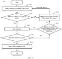
FIG. 1 is a schematic flowchart of a digital pre-distortion processing method according to an embodiment of the present invention; -
FIG. 2 is a schematic diagram of a hardware environment of a digital pre-distortion processing method according to an embodiment of the present invention; -
FIG. 3 is a schematic flowchart of a digital pre-distortion processing method according to another embodiment of the present invention; -
FIG. 4 is a schematic flowchart of a digital pre-distortion processing method according to still another embodiment of the present invention; -
FIG. 5 is a schematic structural diagram of an electronic device according to an embodiment of the present invention; and -
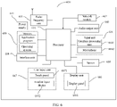
FIG. 6 is a schematic diagram of a hardware structure of an electronic device for implementing embodiments of the present invention. - The following clearly and completely describes the technical solutions in the embodiments of the present invention with reference to the accompanying drawings in the embodiments of the present invention. Apparently, the described embodiments are some rather than all of the embodiments of the present invention. All other embodiments obtained by a person of ordinary skill in the art based on the embodiments of the present invention without creative efforts shall fall within the protection scope of the present invention.
- As shown in
FIG. 1 , an embodiment of the present invention provides a digitalpre-distortion processing method 100. The method may be applied to an electronic device, and includes the following steps. - S 102: Detect a standing wave status of an antenna of the electronic device.
- The antenna in the embodiments of the present invention not only may be a Wi-Fi antenna, but also may be an antenna used in mobile network standards such as Long Term Evolution (Long Term Evolution, LTE) or New Radio (New Radio, NR). The Wi-Fi antenna is used as an example below.
- The detection of the standing wave status of the antenna of the electronic device in this step may specifically be: detection of an offset between a feedback power of a power amplifier (PA) and a feedback power of the antenna. A specific detection principle is shown in
FIG. 2 below. InFIG. 2 , an output end of a pre-distortion module is connected to an input end of the PA, and an output end of the PA is connected to the antenna. - The pre-distortion module can be configured to correct a DPD coefficient according to a power of an input sampling signal and a power of a feedback sampling signal (hereinafter abbreviated as a feedback power). The input sampling signal is a signal inputted to the pre-distortion module, and the feedback sampling signal is determined according to an output signal of the PA, for example, can be detected by a detection pin of a coupler. When the standing wave status of the antenna changes, the feedback power of the detection pin changes. Therefore, in this embodiment, the standing wave status of the antenna can be detected by detecting the feedback power of the detection pin.
- In a preferred embodiment, the coupler shown in
FIG. 2 is a coupler used in a DPD system, and a feedback power detected by the coupler can also be used to correct a DPD coefficient in subsequent steps. In this embodiment, no additional hardware costs are added to the electronic device. This helps to save resources and reduce the volume of the electronic device. - This embodiment of the present invention shows a specific implementation manner of step S102. Certainly, it should be understood that step S102 can also be implemented in other manners, for example, a distance/light/image sensor detects whether the antenna is held by a user, or detects whether a face approaches the antenna, to determine the standing wave status of the antenna. This is not limited in this embodiment of the present invention.
- S104: In a case that the standing wave status of the antenna satisfies a preset working condition, obtain a calibration result through digital pre-distortion calibration.
- In this step, if the standing wave status of the antenna satisfies the preset working condition, it indicates that the standing wave status of the antenna is normal. Specifically, a standing wave ratio of the antenna may be less than a threshold.
- Optionally, the detection of the standing wave status of the antenna of the electronic device in step S102 is: detection of the offset between the feedback power of the PA and the feedback power of the antenna. In this case, that the standing wave status of the antenna in this step satisfies the preset working conditions includes: the offset between the feedback powers is less than or equal to a preset threshold, that is, a difference (absolute value) between a detected feedback power and a preset feedback power is less than or equal to the preset threshold.
- In this embodiment, if the standing wave status of the antenna does not satisfy the preset working condition, for example, the offset between the feedback powers is greater than the preset threshold, that is, a standing wave difference of the antenna, the antenna may be close to a face or may be held by a user with a hand. In this embodiment, DPD calibration can be stopped, to avoid DPD calibration when antenna performance is poor and avoid low DPD calibration accuracy. Certainly, in this embodiment, when DPD calibration is stopped, a DPD function of the electronic device can also be stopped, that is, the pre-distortion module no longer performs DPD processing on an input signal.
- In this step, DPD calibration is performed, and the obtained calibration result may specifically be: the calibration succeeds or the calibration fails.
- Specifically, in this step, DPD calibration may be performed to obtain a DPD coefficient. If the distortion of the PA is within an acceptable range after the pre-distortion module uses the obtained DPD coefficient to enable the DPD function, it is determined that the DPD calibration succeeds. Otherwise, if the distortion of the PA is not within the acceptable range after the pre-distortion module uses the obtained DPD coefficient to enable the DPD function, it is determined that the DPD calibration fails, and the DPD calibration can be performed again later.
- The DPD coefficient can be calculated based on the following models and estimation algorithms: Models include, for example, a memory polynomial model, a Wiener model, a Hammerstein model, or a Volterra model. Estimation algorithms include, for example, the least square method, the least mean square algorithm, or the recursive least square method. The DPD coefficient is used to instruct the pre-distortion module to perform DPD processing on an input signal to obtain a required pre-distorted output signal and input the output signal to the PA, thereby optimizing the linearity of the PA.
- S106: Determine whether to enable a digital pre-distortion function according to the calibration result.
- As mentioned above, the calibration result includes: the calibration succeeds or the calibration fails. If the digital pre-distortion calibration succeeds, the digital pre-distortion function is enabled. If the digital pre-distortion calibration fails, step S104 of performing digital pre-distortion calibration is performed again.
- In the DPD processing method provided in the embodiments of the present invention, the electronic device can detect the standing wave status of the antenna at regular intervals. If the standing wave status meets the preset working condition, that is, when the standing wave of the antenna is normal, the DPD calibration is performed immediately.
- In the embodiments of the present invention, in the process of DPD calibration, a feedback signal fed back by the detection pin of the coupler is captured, the distortion of the PA is analyzed in digital domain, and then a signal inputted to the PA is adjusted (that is, pre-distorted), to reduce the physical distortion of the PA to an acceptable level. If the calibration succeeds (that is, the distortion is at an acceptable level), the digital pre-distortion function is enabled; otherwise, DPD calibration is performed again.
- In the DPD processing method provided in the embodiments of the present invention, the standing wave status of the antenna is detected, the calibration result is obtained through digital pre-distortion calibration when the standing wave status satisfies the preset working condition, and whether to enable the digital pre-distortion function is determined according to the calibration result.
- The embodiments of the present invention can avoid the problem of low DPD calibration accuracy caused because DPD calibration is performed when the standing wave of the antenna is poor, to improve the DPD calibration accuracy, reduce the distortion of the PA, improve the radio frequency performance, and facilitate the optimization of an error vector magnitude (Error Vector Magnitude, EVM) and an adjacent channel power ratio (Adjacent Channel Power Ratio, ACPR) of the PA.
- In addition, the embodiments of the present invention may be implemented at preset time intervals, that is, DPD calibration is performed at preset time intervals. Compared with DPD calibration performed only when the PA is started, DPD calibration accuracy can be further improved.
- The improvement of the DPD calibration accuracy in the embodiments of this specification may specifically be improvement of the accuracy of the obtained DPD coefficient.
- DPD calibration performed when the standing wave of the antenna is poor lead to deterioration of radio frequency performance. If DPD calibration is performed again at regular intervals through the foregoing
embodiment 100, the impact of DPD deterioration on radio frequency performance can be largely avoided. However, frequent DPD calibration degrades Wi-Fi performance. This is because a radio frequency link cannot perform normal communication during DPD calibration, and time resources occupied by DPD calibration reduce the throughput of Wi-Fi. Optionally, before digital pre-distortion calibration is performed in S104 of the foregoing embodiment, the following step may be further included: detecting a throughput of wireless-fidelity Wi-Fi of the electronic device. In this case, S104 of the foregoing embodiment may specifically be: obtaining the calibration result through digital pre-distortion calibration in a case that the standing wave status satisfies the preset working condition and the throughput of the Wi-Fi is less than a preset threshold. - In this embodiment, the throughput of the Wi-Fi is fully considered during DPD calibration, and DPD calibration is performed when the throughput of the Wi-Fi is less than the preset threshold, to minimize the impact of DPD calibration on Wi-Fi and improve Wi-Fi communication efficiency.
- In practical applications, the electronic device may support Wi-Fi connection in a plurality of bands, that is, a radio frequency module of the electronic device has a plurality of Wi-Fi operating bands, and the obtaining the calibration result through digital pre-distortion calibration in a case that the standing wave status satisfies the preset working condition and the throughput of the Wi-Fi is less than a preset threshold in the foregoing embodiment includes:
- in a case that the standing wave status satisfies the preset working condition and a throughput of a target band is less than the preset threshold,
- performing digital pre-distortion calibration on the target band to obtain the calibration result, and performing data transmission by using at least one Wi-Fi band other than the target band; where
- the target band is at least one band of the plurality of Wi-Fi operating bands.
- In this embodiment, the throughput of the Wi-Fi is fully considered during DPD calibration, and DPD calibration is performed when the throughput of the Wi-Fi is less than the preset threshold, to minimize the impact of DPD calibration on Wi-Fi and improve Wi-Fi communication efficiency.
- To describe in detail the digital pre-distortion processing method provided in the embodiments of the present invention, several specific embodiments are described below. As shown in
FIG. 3 , theembodiment 300 includes the following steps. - S302: Detect a standing wave status of an antenna of an electronic device.
- S304: Determine whether the standing wave status of the antenna is normal.
- If yes, execute S308.
- If not, execute S306.
- S306: Skip performing DPD calibration and disable a DPD function.
- S308: Perform DPD calibration.
- S310: Determine whether DPD calibration succeeds.
- If yes, execute S314.
- If not, execute S312.
- S312: Determine whether the number of DPD calibrations is less than the maximum number of calibrations.
- If yes, execute S308.
- If not, execute S306.
- S314: Store a DPD calibration result.
- The DPD calibration result includes a DPD coefficient. When a PA subsequently operates, a signal inputted to the PA can be pre-distorted according to the DPD coefficient, thereby ensuring the linearity of the PA and reducing the distortion of PA.
- The embodiments of the present invention can avoid the problem of low DPD calibration accuracy caused because DPD calibration is performed when an antenna standing wave is poor, to improve the DPD calibration accuracy and reduce the distortion of the PA, improve the radio frequency performance, and facilitate the optimization of an EVM and an ACPR of the PA.
-
FIG. 4 is a digital pre-distortion processing method provided in another embodiment of the present invention. As shown inFIG. 4 , thisembodiment 400 includes the following steps. - S402: Detect a DPD re-calibration time.
- S404: Determine whether a DPD re-calibration cycle is reached.
- If yes, execute S406.
- If not, continue to execute S402.
- S406: Detect a throughput of Wi-Fi of the electronic device.
- S408: Determine whether the throughput of Wi-Fi is less than a preset threshold.
- If yes, execute S410.
- If not, continue to execute S402.
- S410: Detect a standing wave status of an antenna of the electronic device.
- Subsequent steps in this embodiment may continue to be performed with reference to S304 to S314 in the foregoing embodiment. To avoid repetition, the description of the foregoing repeated steps are omitted herein.
- The embodiments of the present invention can avoid the problem of low DPD calibration accuracy caused because DPD calibration is performed when an antenna standing wave is poor, to improve the DPD calibration accuracy and reduce the distortion of the PA, improve the radio frequency performance, and facilitate the optimization of an EVM and an ACPR of the PA.
- In this embodiment, the throughput of the Wi-Fi is fully considered during DPD calibration, and DPD calibration is performed when the throughput of the Wi-Fi is less than the preset threshold, to minimize the impact of DPD calibration on Wi-Fi and improve Wi-Fi communication efficiency.
- Optionally, in this embodiment, when the radio frequency module of the electronic device has a plurality of Wi-Fi operating bands (for example, when the electronic device can use 2.4G and 5G Wi-Fi at the same time), traffic usage statuses of 2.4G and 5G bands can be monitored simultaneously in the background. DPD re-calibration is performed on a band that does not use Wi-Fi traffic.
- The digital pre-distortion processing method according to the embodiments of the present invention is described in detail above with reference to
FIG. 1 to FIG. 4 . The electronic device according to the embodiments of the present invention will be described in detail below with reference toFIG. 5. FIG. 5 is a schematic structural diagram of an electronic device according to an embodiment of the present invention. As shown inFIG. 5 , theelectronic device 500 includes: - a standing wave status detection module 502, configured to detect a standing wave status of an antenna of the electronic device; and
- a
pre-distortion module 504, configured to obtain a calibration result through digital pre-distortion calibration in a case that the standing wave status satisfies a preset working condition; where - the
pre-distortion module 504 may be further configured to determine whether to enable a digital pre-distortion function according to the calibration result. - In the embodiments of the present invention, the standing wave status of the antenna is detected, in the case that the standing wave status satisfies the preset working condition, the calibration result is obtained through digital pre-distortion calibration, and whether to enable the digital pre-distortion function is determined according to the calibration result. The embodiments of the present invention can avoid the problem of low DPD calibration accuracy caused because DPD calibration is performed when an antenna standing wave is poor, to improve the DPD calibration accuracy and reduce the distortion of the PA.
- Optionally, as an embodiment, the
electronic device 500 further includes: a throughput detection module, configured to detect a throughput of Wi-Fi of the electronic device; and
thepre-distortion module 504 is configured to: obtain the calibration result through digital pre-distortion calibration in a case that the standing wave status satisfies the preset working condition and the throughput of the Wi-Fi is less than a first threshold. - Optionally, as an embodiment, a radio frequency module of the terminal device has a plurality of Wi-Fi operating bands, and the
pre-distortion module 504 is configured to: - in a case that the standing wave status satisfies the preset working condition and a throughput of a target band is less than the first threshold,
- perform digital pre-distortion calibration on the target band to obtain the calibration result, and perform data transmission by using at least one Wi-Fi band other than the target band; where
- the target band is at least one band of the plurality of Wi-Fi operating bands.
- Optionally, as an embodiment, the
pre-distortion module 504 is configured to: - in a case that digital pre-distortion calibration succeeds, enable the digital pre-distortion function; and
- in a case that digital pre-distortion calibration fails, perform digital pre-distortion calibration again.
- Optionally, as an embodiment, the standing wave status detection module 502 is configured to: detect an offset between a feedback power of a power amplifier of the electronic device and a feedback power of the antenna; and
in a case that the offset is less than or equal to a second threshold, determine that the standing wave status satisfies the preset working condition. - For the electronic device according to this embodiment of the present invention, refer to the corresponding procedure of the digital pre-distortion processing method according to an embodiment of the present invention, and each unit/module in and the foregoing other operations and/or functions of the electronic device are used to implement the corresponding procedure of the digital pre-distortion processing method, and will no longer be described herein for the purpose of brevity.
-
FIG. 6 is a schematic structural diagram of hardware of an electronic device implementing the embodiments of the present invention. The electronic device 600 includes but is not limited to: aradio frequency unit 601, anetwork module 602, anaudio output unit 603, aninput unit 604, asensor 605, adisplay unit 606, auser input unit 607, aninterface unit 608, amemory 609, aprocessor 610, apower supply 611, and other components. A person skilled in the art may understand that the structure of the electronic device shown inFIG. 6 constitutes no limitation on the electronic device. The electronic device may include more or fewer components than those shown in the figure, or a combination of some components, or an arrangement of different components. In this embodiment of the present invention, the electronic device includes but is not limited to a mobile phone, a tablet computer, a notebook computer, a palmtop computer, an in-vehicle terminal, a wearable device, a pedometer, and the like. - The
processor 610 is configured to: detect a standing wave status of an antenna of the electronic device; obtain a calibration result through digital pre-distortion calibration in a case that the standing wave status satisfies a preset working condition; and determine whether to enable a digital pre-distortion function according to the calibration result. - In the embodiments of the present invention, the standing wave status of the antenna of the electronic device is detected, in the case that the standing wave status satisfies the preset working condition, the calibration result is obtained through digital pre-distortion calibration, and whether to enable the digital pre-distortion function is determined according to the calibration result. The embodiments of the present invention can avoid the problem of low DPD calibration accuracy caused because DPD calibration is performed when an antenna standing wave is poor, to improve the DPD calibration accuracy and reduce the distortion of the PA.
- It should be understood that in this embodiment of the present invention, the
radio frequency unit 601 may be configured to receive and transmit information, or receive and transmit signals during a call. Specifically, the radio frequency unit receives downlink data from a base station, and transmits the downlink data to theprocessor 610 for processing; and transmits uplink data to the base station. Generally, theradio frequency unit 601 includes, but is not limited to, an antenna, at least one amplifier, a transceiver, a coupler, a low noise amplifier, and a duplexer. In addition, theradio frequency unit 601 may also communicate with a network and other devices through a wireless communication system. - The electronic device provides users with wireless broadband Internet access through the
network module 602, for example, helps users receive and send e-mails, browse web pages, and access streaming media. - The
audio output unit 603 may convert audio data received by theradio frequency unit 601 or thenetwork module 602 or stored in thememory 609 into an audio signal and output the audio signal as a sound. Moreover, theaudio output unit 603 can further provide audio output related to a specific function performed the electronic device 600 (for example, call signal receiving sound and message receiving sound). Theaudio output unit 603 includes a speaker, a buzzer, a telephone receiver, and the like. - The
input unit 604 is configured to receive audio or radio frequency signals. Theinput unit 604 may include a graphics processing unit (Graphics Processing Unit, GPU) 6041 and amicrophone 6042, and thegraphics processing unit 6041 processes image data of a still picture or video obtained by an image capture device (such as a camera) in a video capture mode or an image capture mode. A processed image frame may be displayed on thedisplay unit 606. The image frame processed by thegraphics processing unit 6041 may be stored in the memory 609 (or another storage medium) or sent by using theradio frequency unit 601 or thenetwork module 602. Themicrophone 6042 may receive sound and can process such sound into audio data. The audio data obtained through processing may be converted, in a telephone call mode, into a format that may be sent to a mobile communication base station via theradio frequency unit 601 for output. - The electronic device 600 further includes at least one
sensor 605, for example, a light sensor, a motion sensor, and another sensor. Specifically, the light sensor includes an ambient light sensor and a proximity sensor. The ambient light sensor may adjust brightness of adisplay panel 6061 according to ambient light brightness. The proximity sensor may switch off thedisplay panel 6061 and/or backlight when the electronic device 600 moves close to an ear. As a motion sensor, an accelerometer sensor may detect magnitude of acceleration in various directions (usually three axes), may detect magnitude and the direction of gravity when stationary, may be configured to identify electronic device postures (such as switching between a landscape mode and a portrait mode, related games, and magnetometer posture calibration), may perform functions related to vibration identification (such as a pedometer and a knock), and the like. Thesensor 605 may further include a fingerprint sensor, a pressure sensor, an iris sensor, a molecular sensor, a gyroscope, a barometer, a hygrometer, a thermometer, an infrared sensor, or the like. Details are not described herein again. - The
display unit 606 is configured to display information entered by the user or information provided for the user. Thedisplay unit 606 may include adisplay panel 6061, and thedisplay panel 6061 may be configured in a form of a liquid crystal display (Liquid Crystal Display, LCD), an organic light-emitting diode (Organic Light-Emitting Diode, OLED), or the like. - The
user input unit 607 may be configured to receive entered number or character information, and generate key signal input related to user settings and function control of the electronic device. Specifically, theuser input unit 607 includes atouch panel 6071 and anotherinput device 6072. Thetouch panel 6071, also called a touch screen, can collect a touch operation of the user on or near the touch panel 6071 (for example, an operation performed by the user with any suitable object or accessory such as a finger or a stylus on or near the touch panel 6071). Thetouch panel 6071 may include two parts: a touch detection apparatus and a touch controller. The touch detection apparatus detects a touch position of the user, detects a signal brought by the touch operation, and transmits the signal to the touch controller. The touch controller receives touch information from the touch detection apparatus, converts the touch information into contact coordinates, and sends the contact coordinates to theprocessor 610, and can receive and execute a command sent by theprocessor 610. In addition, thetouch panel 6071 may be implemented by various types such as a resistive type, a capacitive type, an infrared ray type or a surface acoustic wave type. In addition to thetouch panel 6071, theuser input unit 607 may further include anotherinput device 6072. Specifically, the anotherinput device 6072 may include but is not limited to: a physical keyboard, a function key (such as a volume control key, a switch key), a trackball, a mouse, and a joystick, which is no longer repeated here. - Further, the
touch panel 6071 may cover thedisplay panel 6061. When detecting a touch operation on or near thetouch panel 6071, thetouch panel 6071 transmits the touch operation to theprocessor 610 to determine a type of a touch event. Then, theprocessor 610 provides corresponding visual output on thedisplay panel 6061 based on the type of the touch event. Although inFIG. 6 , thetouch panel 6071 and thedisplay panel 6061 are configured as two independent components to implement input and output functions of the electronic device, in some embodiments, thetouch panel 6071 and thedisplay panel 6061 can be integrated to implement the input and output functions of the electronic device. Details are not limited herein. - The
interface unit 608 is an interface for connecting an external apparatus and the electronic device 600. For example, the external apparatus may include a wired or wireless headset jack, an external power supply (or a battery charger) port, a wired or wireless data port, a storage card port, a port for connecting an apparatus having an identification module, an audio input/output (I/O) port, a video I/O port, a headset jack, or the like. Theinterface unit 608 can be configured to receive input from an external apparatus (for example, data information and power) and transmit the received input to one or more elements in the electronic device 600, or can be configured to transmit data between the electronic device 600 and the external apparatus. - The
memory 609 may be configured to store a software program and various data. Thememory 609 may mainly include a program storage area and a data storage area. The program storage area may store an operating system, an application required by at least one function (for example, a sound play function or an image display function), and the like. The data storage area may store data (for example, audio data or an address book) or the like created based on use of the mobile phone. In addition, thememory 609 may include a high-speed random access memory or a nonvolatile memory, for example, at least one disk storage device, a flash memory, or other volatile solid-state storage devices. - The
processor 610 is a control center of the electronic device and connects all parts of the electronic device using various interfaces and circuits. By running or executing software programs and/or modules stored in thememory 609 and by calling data stored in thememory 609, theprocessor 610 implements various functions of the electronic device and processes data, thus performing overall monitoring on the electronic device. Theprocessor 610 may include one or more processing units. Optionally, theprocessor 610 may integrate an application processor and a modem processor. The application processor mainly deals with an operating system, a user interface, an application, and the like. The modem processor mainly deals with wireless communication. It may be understood that the modem processor may not be integrated into theprocessor 610. - The electronic device 600 may further include the power supply 611 (such as a battery) supplying power to each component. Preferably, the
power supply 611 may be logically connected to theprocessor 610 by using a power management system, so as to implement functions such as charging management, discharging management and power consumption management by using the power management system. - In addition, the electronic device 600 includes some functional modules not shown. Details are not described herein again.
- Preferably, an embodiment of the present invention further provides an electronic device, including a
processor 610, amemory 609, and a computer program stored in thememory 609 and executable on theprocessor 610. When theprocessor 610 executes the computer program, the foregoing processes of themethod embodiments 100 to 400 are implemented and a same technical effect can be achieved. To avoid repetition, details are not described herein again. - An embodiment of the present invention further provides a computer readable storage medium. The computer readable storage medium stores a computer program. When the computer program is executed by a processor, the foregoing processes of the
method embodiments 100 to 400 are implemented, and a same technical effect can be achieved. To avoid repetition, details are not described herein again. The computer-readable storage medium may be a read-only memory (Read-Only Memory, ROM), a random access memory (Random Access Memory, RAM), a magnetic disk, a compact disc, or the like. - An embodiment of the present invention further provides a computer program product. The computer program product is stored in a nonvolatile storage medium. The program product is configured to be executed by at least one processor to implement the foregoing processes of the
method embodiments 100 to 400, and a same technical effect can be achieved. To avoid repetition, details are not described herein again. - An embodiment of the present invention further provides a chip, where the chip includes a processor and a communication interface, the communication interface is coupled to the processor, and the processor is configured to run a program or an instruction to implement the foregoing processes of the
method embodiments 100 to 400, and a same technical effect can be achieved. To avoid repetition, details are not described herein again. - An embodiment of the present invention further provides a digital pre-distortion processing apparatus. The digital pre-distortion processing apparatus is configured to implement the foregoing processes of the
method embodiments 100 to 400, and a same technical effect can be achieved. To avoid repetition, details are not described herein again. - It should be noted that in this specification, the term "include", "including", or any other variant is intended to cover non-exclusive inclusion, so that a process, method, article, or apparatus that includes a series of elements includes not only those elements but also other elements that are not explicitly listed, or includes elements inherent to such a process, method, article, or apparatus. Without more restrictions, an element defined by the statement "including a..." does not exclude another same element in this process, method, article, or apparatus that includes the element.
- Based on the foregoing descriptions of the embodiments, a person skilled in the art may clearly understand that the method in the foregoing embodiment may be implemented by software in addition to a necessary universal hardware platform or by hardware only. In most circumstances, the former is a preferred implementation manner. Based on such understanding, the technical solutions of the present invention essentially or the part contributing to the prior art may be implemented in a form of a software product. The computer software product is stored in a storage medium (such as a ROM/RAM, a hard disk, or an optical disc), and includes several instructions for instructing a terminal (which may be mobile phone, a computer, a server, an air conditioner, a network device, or the like) to perform the methods described in the embodiments of the present invention.
- The embodiments of the present invention are described above with reference to the accompanying drawings, but the present invention is not limited to the foregoing specific implementations, and the foregoing specific implementations are only illustrative and not restrictive. Under the enlightenment of the present invention, a person of ordinary skill in the art can make many forms without departing from the purpose of the present invention and the protection scope of the claims, and all of these fall within the protection of the present invention.
Claims (15)
- A digital pre-distortion processing method, applied to an electronic device, and characterized by comprising:detecting a standing wave status of an antenna of the electronic device;obtaining a calibration result through digital pre-distortion calibration in a case that the standing wave status satisfies a preset working condition; anddetermining whether to enable a digital pre-distortion function according to the calibration result.
- The method according to claim 1, characterized in that before the obtaining a calibration result through digital pre-distortion calibration in a case that the standing wave status satisfies a preset working condition, the method further comprises:detecting a throughput of wireless-fidelity Wi-Fi of the electronic device; andthe obtaining a calibration result through digital pre-distortion calibration in a case that the standing wave status satisfies a preset working condition comprises:
obtaining the calibration result through digital pre-distortion calibration in a case that the standing wave status satisfies the preset working condition and the throughput of the Wi-Fi is less than a first threshold. - The method according to claim 2, characterized in that a radio frequency module of the electronic device has a plurality of Wi-Fi operating bands, and the obtaining the calibration result through digital pre-distortion calibration in a case that the standing wave status satisfies the preset working condition and the throughput of the Wi-Fi is less than a first threshold comprises:in a case that the standing wave status satisfies the preset working condition and a throughput of a target band is less than the first threshold,performing digital pre-distortion calibration on the target band to obtain the calibration result, and performing data transmission by using at least one Wi-Fi band other than the target band; whereinthe target band is at least one band of the plurality of Wi-Fi operating bands.
- The method according to claim 1, characterized in that the determining whether to enable a digital pre-distortion function according to the calibration result comprises:in a case that digital pre-distortion calibration succeeds, enabling the digital pre-distortion function; andin a case that digital pre-distortion calibration fails, performing digital pre-distortion calibration again.
- The method according to claim 1, wherein the detecting a standing wave status of an antenna of the electronic device comprises:detecting an offset between a feedback power of a power amplifier of the electronic device and a feedback power of the antenna; andin a case that the offset is less than or equal to a second threshold, determining that the standing wave status satisfies the preset working condition.
- An electronic device, characterized by comprising:a standing wave status detection module, configured to detect a standing wave status of an antenna of the electronic device; anda pre-distortion module, configured to obtain a calibration result through digital pre-distortion calibration in a case that the standing wave status satisfies a preset working condition; whereinthe pre-distortion module is further configured to determine whether to enable a digital pre-distortion function according to the calibration result.
- The electronic device according to claim 6, characterized by further comprising:a throughput detection module, configured to detect a throughput of Wi-Fi of the electronic device; andthe pre-distortion module, configured to obtain the calibration result through digital pre-distortion calibration in a case that the standing wave status satisfies the preset working condition and the throughput of the Wi-Fi is less than a first threshold.
- The electronic device according to claim 7, characterized in that a radio frequency module of the electronic device has a plurality of Wi-Fi operating bands, and the pre-distortion module is configured to: in a case that the standing wave status satisfies the preset working condition and a throughput of a target band is less than the first threshold, perform digital pre-distortion calibration on the target band to obtain the calibration result, and perform data transmission by using at least one Wi-Fi band other than the target band; wherein
the target band is at least one band of the plurality of Wi-Fi operating bands. - The electronic device according to claim 6, characterized in that the pre-distortion module is configured to:in a case that digital pre-distortion calibration succeeds, enable the digital pre-distortion function; andin a case that digital pre-distortion calibration fails, perform digital pre-distortion calibration again.
- The electronic device according to claim 6, characterized in that the standing wave status detection module is configured to: detect an offset between a feedback power of a power amplifier of the electronic device and a feedback power of the antenna; and
in a case that the offset is less than or equal to a second threshold, determine that the standing wave status satisfies the preset working condition. - An electronic device, characterized by comprising a processor, a memory, and a computer program stored in the memory and executable on the processor, wherein when the computer program is executed by the processor, the method according to any one of claims 1 to 5 is implemented.
- A computer-readable storage medium, characterized in that the computer-readable storage medium stores a computer program, and when the computer program is executed by a processor, the method according to any one of claims 1 to 5 is implemented.
- A computer program product, wherein the computer program product is stored in a nonvolatile storage medium, and the program product is configured to be executed by at least one processor to implement the method according to any one of claims 1 to 5.
- A chip, including a processor and a communication interface, wherein the communication interface is coupled to the processor, and the processor is configured to run a program or an instruction to implement the method according to any one of claims 1 to 5.
- A digital pre-distortion processing apparatus, wherein the digital pre-distortion processing apparatus is configured to perform the method according to any one of claims 1 to 5.
Applications Claiming Priority (2)
| Application Number | Priority Date | Filing Date | Title |
|---|---|---|---|
| CN201911060466.XA CN110912624B (en) | 2019-11-01 | 2019-11-01 | Digital predistortion processing method and electronic device |
| PCT/CN2020/123777 WO2021083093A1 (en) | 2019-11-01 | 2020-10-26 | Digital pre-distortion processing method and electronic device |
Publications (3)
| Publication Number | Publication Date |
|---|---|
| EP4050819A1 true EP4050819A1 (en) | 2022-08-31 |
| EP4050819A4 EP4050819A4 (en) | 2022-12-21 |
| EP4050819B1 EP4050819B1 (en) | 2025-01-01 |
Family
ID=69815758
Family Applications (1)
| Application Number | Title | Priority Date | Filing Date |
|---|---|---|---|
| EP20881467.3A Active EP4050819B1 (en) | 2019-11-01 | 2020-10-26 | Digital pre-distortion processing method and electronic device |
Country Status (5)
| Country | Link |
|---|---|
| US (1) | US12021571B2 (en) |
| EP (1) | EP4050819B1 (en) |
| CN (1) | CN110912624B (en) |
| ES (1) | ES3006691T3 (en) |
| WO (1) | WO2021083093A1 (en) |
Families Citing this family (3)
| Publication number | Priority date | Publication date | Assignee | Title |
|---|---|---|---|---|
| CN114640560B (en) * | 2022-03-29 | 2024-03-08 | Oppo广东移动通信有限公司 | Signal processing method and device, baseband device and terminal equipment |
| CN117743647A (en) * | 2022-09-14 | 2024-03-22 | 北京小米移动软件有限公司 | Radio frequency file inspection method, device, electronic equipment and readable storage medium |
| US12136959B2 (en) * | 2023-03-28 | 2024-11-05 | Cisco Technology, Inc. | Real-time radio self-calibration |
Family Cites Families (10)
| Publication number | Priority date | Publication date | Assignee | Title |
|---|---|---|---|---|
| US6252456B1 (en) * | 1999-07-29 | 2001-06-26 | Motorola, Inc. | Power amplifier load controller and method for controlling a power amplifier load |
| US8085869B2 (en) * | 2008-02-14 | 2011-12-27 | Broadcom Corporation | Configurable load impedance for power amplifier predistortion calibration |
| CN101626355B (en) * | 2009-08-11 | 2012-11-14 | 北京天碁科技有限公司 | Calibration device and calibration method of multi-input multi-output (MIMO) terminal |
| CN101834677B (en) * | 2010-03-11 | 2013-12-04 | 京信通信系统(中国)有限公司 | Base band power statistic-based standing wave detecting system and method for radio frequency remote system |
| US8908751B2 (en) * | 2011-02-28 | 2014-12-09 | Intel Mobile Communications GmbH | Joint adaptive bias point adjustment and digital pre-distortion for power amplifier |
| JP5751324B2 (en) * | 2011-05-30 | 2015-07-22 | 日本電気株式会社 | VSWR measurement circuit, wireless communication apparatus, VSWR measurement method, and VSWR measurement program |
| CN104580043B (en) * | 2014-12-17 | 2018-01-02 | 华南理工大学 | A kind of digital pre-distortion system and its method |
| JP2016213603A (en) * | 2015-05-01 | 2016-12-15 | 富士通株式会社 | Wireless communication device |
| WO2019070573A1 (en) * | 2017-10-02 | 2019-04-11 | Nanosemi, Inc. | Digital predistortion adjustment based on determination of load condition characteristics |
| CN108738122B (en) * | 2018-04-03 | 2019-12-31 | 京信通信系统(中国)有限公司 | Digital predistortion power amplifier calibration method, system and digital predistortion device |
-
2019
- 2019-11-01 CN CN201911060466.XA patent/CN110912624B/en active Active
-
2020
- 2020-10-26 WO PCT/CN2020/123777 patent/WO2021083093A1/en not_active Ceased
- 2020-10-26 EP EP20881467.3A patent/EP4050819B1/en active Active
- 2020-10-26 ES ES20881467T patent/ES3006691T3/en active Active
-
2022
- 2022-04-29 US US17/733,995 patent/US12021571B2/en active Active
Also Published As
| Publication number | Publication date |
|---|---|
| CN110912624B (en) | 2021-08-31 |
| ES3006691T3 (en) | 2025-03-18 |
| EP4050819B1 (en) | 2025-01-01 |
| CN110912624A (en) | 2020-03-24 |
| US20220263589A1 (en) | 2022-08-18 |
| EP4050819A4 (en) | 2022-12-21 |
| WO2021083093A1 (en) | 2021-05-06 |
| US12021571B2 (en) | 2024-06-25 |
Similar Documents
| Publication | Publication Date | Title |
|---|---|---|
| EP3855709A1 (en) | Angle determination circuit and method, and folding screen terminal | |
| CN107889151B (en) | Measurement report reporting method, mobile terminal and computer readable storage medium | |
| CN109905812B (en) | Input power control method and device and terminal equipment | |
| US12021571B2 (en) | Digital pre-distortion processing method and electronic device | |
| CN109819450B (en) | Signal receiving method, device and terminal | |
| CN109379145B (en) | A signal processing circuit, terminal equipment and signal processing method | |
| CN110266323B (en) | A signal control circuit, terminal equipment and signal control method | |
| CN110099434B (en) | A power adjustment method, terminal device and computer-readable storage medium | |
| CN110399000B (en) | A kind of mobile terminal and its temperature control method | |
| CN110289885B (en) | A kind of antenna tuning method and terminal | |
| CN110365347B (en) | Power amplifier control method, device and computer readable storage medium | |
| CN110289883B (en) | Radio frequency circuit, terminal equipment and circuit control method | |
| CN108649991A (en) | A kind of processing method and mobile terminal of harmonic wave interference | |
| CN109739394B (en) | SAR value processing method and mobile terminal | |
| CN113556427A (en) | Mobile terminal radiation recording method and device, mobile terminal and storage medium | |
| CN109348504A (en) | Power detection method, mobile terminal and power detection circuit | |
| CN110636530B (en) | Method for processing adjacent channel interference and terminal equipment | |
| US12137381B2 (en) | Random access method and terminal | |
| CN110012529B (en) | A gain mode switching method and mobile terminal | |
| CN110995302B (en) | A gain stage adjustment method and electronic device | |
| CN110730013B (en) | Method for improving transmission stray and mobile terminal | |
| US20210092766A1 (en) | Random Access Resource Selection Method And Terminal Device | |
| CN108600129A (en) | Signal processing method and mobile terminal | |
| CN113099542A (en) | Parameter reporting method, uplink scheduling method, device and medium | |
| CN110086483A (en) | A kind of communication control method and terminal |
Legal Events
| Date | Code | Title | Description |
|---|---|---|---|
| STAA | Information on the status of an ep patent application or granted ep patent |
Free format text: STATUS: THE INTERNATIONAL PUBLICATION HAS BEEN MADE |
|
| PUAI | Public reference made under article 153(3) epc to a published international application that has entered the european phase |
Free format text: ORIGINAL CODE: 0009012 |
|
| STAA | Information on the status of an ep patent application or granted ep patent |
Free format text: STATUS: REQUEST FOR EXAMINATION WAS MADE |
|
| 17P | Request for examination filed |
Effective date: 20220524 |
|
| AK | Designated contracting states |
Kind code of ref document: A1 Designated state(s): AL AT BE BG CH CY CZ DE DK EE ES FI FR GB GR HR HU IE IS IT LI LT LU LV MC MK MT NL NO PL PT RO RS SE SI SK SM TR |
|
| A4 | Supplementary search report drawn up and despatched |
Effective date: 20221122 |
|
| RIC1 | Information provided on ipc code assigned before grant |
Ipc: H04B 17/13 20150101ALI20221116BHEP Ipc: H04B 17/21 20150101ALI20221116BHEP Ipc: H04B 17/11 20150101AFI20221116BHEP |
|
| DAV | Request for validation of the european patent (deleted) | ||
| DAX | Request for extension of the european patent (deleted) | ||
| STAA | Information on the status of an ep patent application or granted ep patent |
Free format text: STATUS: EXAMINATION IS IN PROGRESS |
|
| 17Q | First examination report despatched |
Effective date: 20230921 |
|
| GRAP | Despatch of communication of intention to grant a patent |
Free format text: ORIGINAL CODE: EPIDOSNIGR1 |
|
| STAA | Information on the status of an ep patent application or granted ep patent |
Free format text: STATUS: GRANT OF PATENT IS INTENDED |
|
| INTG | Intention to grant announced |
Effective date: 20241004 |
|
| GRAS | Grant fee paid |
Free format text: ORIGINAL CODE: EPIDOSNIGR3 |
|
| GRAA | (expected) grant |
Free format text: ORIGINAL CODE: 0009210 |
|
| STAA | Information on the status of an ep patent application or granted ep patent |
Free format text: STATUS: THE PATENT HAS BEEN GRANTED |
|
| AK | Designated contracting states |
Kind code of ref document: B1 Designated state(s): AL AT BE BG CH CY CZ DE DK EE ES FI FR GB GR HR HU IE IS IT LI LT LU LV MC MK MT NL NO PL PT RO RS SE SI SK SM TR |
|
| REG | Reference to a national code |
Ref country code: GB Ref legal event code: FG4D |
|
| REG | Reference to a national code |
Ref country code: DE Ref legal event code: R096 Ref document number: 602020044286 Country of ref document: DE |
|
| REG | Reference to a national code |
Ref country code: CH Ref legal event code: EP |
|
| REG | Reference to a national code |
Ref country code: IE Ref legal event code: FG4D |
|
| REG | Reference to a national code |
Ref country code: NL Ref legal event code: FP |
|
| REG | Reference to a national code |
Ref country code: ES Ref legal event code: FG2A Ref document number: 3006691 Country of ref document: ES Kind code of ref document: T3 Effective date: 20250318 |
|
| REG | Reference to a national code |
Ref country code: LT Ref legal event code: MG9D |
|
| REG | Reference to a national code |
Ref country code: AT Ref legal event code: MK05 Ref document number: 1757371 Country of ref document: AT Kind code of ref document: T Effective date: 20250101 |
|
| PG25 | Lapsed in a contracting state [announced via postgrant information from national office to epo] |
Ref country code: FI Free format text: LAPSE BECAUSE OF FAILURE TO SUBMIT A TRANSLATION OF THE DESCRIPTION OR TO PAY THE FEE WITHIN THE PRESCRIBED TIME-LIMIT Effective date: 20250101 |
|
| PG25 | Lapsed in a contracting state [announced via postgrant information from national office to epo] |
Ref country code: PL Free format text: LAPSE BECAUSE OF FAILURE TO SUBMIT A TRANSLATION OF THE DESCRIPTION OR TO PAY THE FEE WITHIN THE PRESCRIBED TIME-LIMIT Effective date: 20250101 |
|
| PG25 | Lapsed in a contracting state [announced via postgrant information from national office to epo] |
Ref country code: NO Free format text: LAPSE BECAUSE OF FAILURE TO SUBMIT A TRANSLATION OF THE DESCRIPTION OR TO PAY THE FEE WITHIN THE PRESCRIBED TIME-LIMIT Effective date: 20250401 Ref country code: IS Free format text: LAPSE BECAUSE OF FAILURE TO SUBMIT A TRANSLATION OF THE DESCRIPTION OR TO PAY THE FEE WITHIN THE PRESCRIBED TIME-LIMIT Effective date: 20250501 |
|
| PG25 | Lapsed in a contracting state [announced via postgrant information from national office to epo] |
Ref country code: HR Free format text: LAPSE BECAUSE OF FAILURE TO SUBMIT A TRANSLATION OF THE DESCRIPTION OR TO PAY THE FEE WITHIN THE PRESCRIBED TIME-LIMIT Effective date: 20250101 |
|
| PG25 | Lapsed in a contracting state [announced via postgrant information from national office to epo] |
Ref country code: LV Free format text: LAPSE BECAUSE OF FAILURE TO SUBMIT A TRANSLATION OF THE DESCRIPTION OR TO PAY THE FEE WITHIN THE PRESCRIBED TIME-LIMIT Effective date: 20250101 Ref country code: PT Free format text: LAPSE BECAUSE OF FAILURE TO SUBMIT A TRANSLATION OF THE DESCRIPTION OR TO PAY THE FEE WITHIN THE PRESCRIBED TIME-LIMIT Effective date: 20250502 |
|
| PG25 | Lapsed in a contracting state [announced via postgrant information from national office to epo] |
Ref country code: GR Free format text: LAPSE BECAUSE OF FAILURE TO SUBMIT A TRANSLATION OF THE DESCRIPTION OR TO PAY THE FEE WITHIN THE PRESCRIBED TIME-LIMIT Effective date: 20250402 Ref country code: BG Free format text: LAPSE BECAUSE OF FAILURE TO SUBMIT A TRANSLATION OF THE DESCRIPTION OR TO PAY THE FEE WITHIN THE PRESCRIBED TIME-LIMIT Effective date: 20250101 |
|
| PG25 | Lapsed in a contracting state [announced via postgrant information from national office to epo] |
Ref country code: AT Free format text: LAPSE BECAUSE OF FAILURE TO SUBMIT A TRANSLATION OF THE DESCRIPTION OR TO PAY THE FEE WITHIN THE PRESCRIBED TIME-LIMIT Effective date: 20250101 |
|
| PG25 | Lapsed in a contracting state [announced via postgrant information from national office to epo] |
Ref country code: CZ Free format text: LAPSE BECAUSE OF FAILURE TO SUBMIT A TRANSLATION OF THE DESCRIPTION OR TO PAY THE FEE WITHIN THE PRESCRIBED TIME-LIMIT Effective date: 20250101 |
|
| PG25 | Lapsed in a contracting state [announced via postgrant information from national office to epo] |
Ref country code: SE Free format text: LAPSE BECAUSE OF FAILURE TO SUBMIT A TRANSLATION OF THE DESCRIPTION OR TO PAY THE FEE WITHIN THE PRESCRIBED TIME-LIMIT Effective date: 20250101 |
|
| REG | Reference to a national code |
Ref country code: DE Ref legal event code: R097 Ref document number: 602020044286 Country of ref document: DE |
|
| PG25 | Lapsed in a contracting state [announced via postgrant information from national office to epo] |
Ref country code: SM Free format text: LAPSE BECAUSE OF FAILURE TO SUBMIT A TRANSLATION OF THE DESCRIPTION OR TO PAY THE FEE WITHIN THE PRESCRIBED TIME-LIMIT Effective date: 20250101 |
|
| PG25 | Lapsed in a contracting state [announced via postgrant information from national office to epo] |
Ref country code: DK Free format text: LAPSE BECAUSE OF FAILURE TO SUBMIT A TRANSLATION OF THE DESCRIPTION OR TO PAY THE FEE WITHIN THE PRESCRIBED TIME-LIMIT Effective date: 20250101 |
|
| PGFP | Annual fee paid to national office [announced via postgrant information from national office to epo] |
Ref country code: IT Payment date: 20250922 Year of fee payment: 6 Ref country code: NL Payment date: 20250912 Year of fee payment: 6 |
|
| PGFP | Annual fee paid to national office [announced via postgrant information from national office to epo] |
Ref country code: GB Payment date: 20250904 Year of fee payment: 6 |
|
| PGFP | Annual fee paid to national office [announced via postgrant information from national office to epo] |
Ref country code: FR Payment date: 20250908 Year of fee payment: 6 |
|
| PGFP | Annual fee paid to national office [announced via postgrant information from national office to epo] |
Ref country code: SE Payment date: 20250929 Year of fee payment: 6 |
|
| PG25 | Lapsed in a contracting state [announced via postgrant information from national office to epo] |
Ref country code: EE Free format text: LAPSE BECAUSE OF FAILURE TO SUBMIT A TRANSLATION OF THE DESCRIPTION OR TO PAY THE FEE WITHIN THE PRESCRIBED TIME-LIMIT Effective date: 20250101 |
|
| PG25 | Lapsed in a contracting state [announced via postgrant information from national office to epo] |
Ref country code: RO Free format text: LAPSE BECAUSE OF FAILURE TO SUBMIT A TRANSLATION OF THE DESCRIPTION OR TO PAY THE FEE WITHIN THE PRESCRIBED TIME-LIMIT Effective date: 20250101 |
|
| PG25 | Lapsed in a contracting state [announced via postgrant information from national office to epo] |
Ref country code: SK Free format text: LAPSE BECAUSE OF FAILURE TO SUBMIT A TRANSLATION OF THE DESCRIPTION OR TO PAY THE FEE WITHIN THE PRESCRIBED TIME-LIMIT Effective date: 20250101 |
|
| REG | Reference to a national code |
Ref country code: CH Ref legal event code: U11 Free format text: ST27 STATUS EVENT CODE: U-0-0-U10-U11 (AS PROVIDED BY THE NATIONAL OFFICE) Effective date: 20251101 |
|
| PLBE | No opposition filed within time limit |
Free format text: ORIGINAL CODE: 0009261 |
|
| STAA | Information on the status of an ep patent application or granted ep patent |
Free format text: STATUS: NO OPPOSITION FILED WITHIN TIME LIMIT |
|
| PGFP | Annual fee paid to national office [announced via postgrant information from national office to epo] |
Ref country code: LU Payment date: 20251016 Year of fee payment: 6 |
|
| 26N | No opposition filed |
Effective date: 20251002 |
|
| PGFP | Annual fee paid to national office [announced via postgrant information from national office to epo] |
Ref country code: DE Payment date: 20250902 Year of fee payment: 6 |
|
| PGFP | Annual fee paid to national office [announced via postgrant information from national office to epo] |
Ref country code: MC Payment date: 20251002 Year of fee payment: 6 |
|
| PGFP | Annual fee paid to national office [announced via postgrant information from national office to epo] |
Ref country code: BE Payment date: 20251006 Year of fee payment: 6 |
|
| PGFP | Annual fee paid to national office [announced via postgrant information from national office to epo] |
Ref country code: CH Payment date: 20251101 Year of fee payment: 6 |
|
| PGFP | Annual fee paid to national office [announced via postgrant information from national office to epo] |
Ref country code: IE Payment date: 20251001 Year of fee payment: 6 |
|
| PGFP | Annual fee paid to national office [announced via postgrant information from national office to epo] |
Ref country code: MT Payment date: 20251017 Year of fee payment: 6 |
|
| PGFP | Annual fee paid to national office [announced via postgrant information from national office to epo] |
Ref country code: ES Payment date: 20251107 Year of fee payment: 6 |
|
| REG | Reference to a national code |
Ref country code: GB Ref legal event code: 732E Free format text: REGISTERED BETWEEN 20260409 AND 20260415 |