EP4050791A2 - System and method for providing grid-forming control for a double-fed wind turbine generator - Google Patents
System and method for providing grid-forming control for a double-fed wind turbine generator Download PDFInfo
- Publication number
- EP4050791A2 EP4050791A2 EP22153452.2A EP22153452A EP4050791A2 EP 4050791 A2 EP4050791 A2 EP 4050791A2 EP 22153452 A EP22153452 A EP 22153452A EP 4050791 A2 EP4050791 A2 EP 4050791A2
- Authority
- EP
- European Patent Office
- Prior art keywords
- wind turbine
- double
- magnetizing
- turbine generator
- fed wind
- Prior art date
- Legal status (The legal status is an assumption and is not a legal conclusion. Google has not performed a legal analysis and makes no representation as to the accuracy of the status listed.)
- Granted
Links
Images







Classifications
-
- H—ELECTRICITY
- H02—GENERATION; CONVERSION OR DISTRIBUTION OF ELECTRIC POWER
- H02P—CONTROL OR REGULATION OF ELECTRIC MOTORS, ELECTRIC GENERATORS OR DYNAMO-ELECTRIC CONVERTERS; CONTROLLING TRANSFORMERS, REACTORS OR CHOKE COILS
- H02P9/00—Arrangements for controlling electric generators for the purpose of obtaining a desired output
- H02P9/10—Control effected upon generator excitation circuit to reduce harmful effects of overloads or transients, e.g. sudden application of load, sudden removal of load, sudden change of load
- H02P9/105—Control effected upon generator excitation circuit to reduce harmful effects of overloads or transients, e.g. sudden application of load, sudden removal of load, sudden change of load for increasing the stability
-
- H—ELECTRICITY
- H02—GENERATION; CONVERSION OR DISTRIBUTION OF ELECTRIC POWER
- H02J—ELECTRIC POWER NETWORKS; CIRCUIT ARRANGEMENTS OR SYSTEMS FOR SUPPLYING OR DISTRIBUTING ELECTRIC POWER; SYSTEMS FOR STORING ELECTRIC ENERGY
- H02J3/00—Circuit arrangements for AC mains or AC distribution networks
- H02J3/38—Arrangements for feeding a single network from two or more generators or sources in parallel; Arrangements for feeding already energised networks from additional generators or sources in parallel
- H02J3/381—Dispersed generators
-
- F—MECHANICAL ENGINEERING; LIGHTING; HEATING; WEAPONS; BLASTING
- F03—MACHINES OR ENGINES FOR LIQUIDS; WIND, SPRING, OR WEIGHT MOTORS; PRODUCING MECHANICAL POWER OR A REACTIVE PROPULSIVE THRUST, NOT OTHERWISE PROVIDED FOR
- F03D—WIND MOTORS
- F03D9/00—Adaptations of wind motors for special use; Combinations of wind motors with apparatus driven thereby; Wind motors specially adapted for installation in particular locations
- F03D9/20—Wind motors characterised by the driven apparatus
- F03D9/25—Wind motors characterised by the driven apparatus the apparatus being an electrical generator
- F03D9/255—Wind motors characterised by the driven apparatus the apparatus being an electrical generator connected to electrical distribution networks; Arrangements therefor
-
- H—ELECTRICITY
- H02—GENERATION; CONVERSION OR DISTRIBUTION OF ELECTRIC POWER
- H02J—ELECTRIC POWER NETWORKS; CIRCUIT ARRANGEMENTS OR SYSTEMS FOR SUPPLYING OR DISTRIBUTING ELECTRIC POWER; SYSTEMS FOR STORING ELECTRIC ENERGY
- H02J3/00—Circuit arrangements for AC mains or AC distribution networks
- H02J3/38—Arrangements for feeding a single network from two or more generators or sources in parallel; Arrangements for feeding already energised networks from additional generators or sources in parallel
- H02J3/46—Controlling the sharing of generated power between the generators, sources or networks
- H02J3/466—Scheduling or selectively controlling the operation of the generators or sources, e.g. connecting or disconnecting generators to meet a demand
-
- H—ELECTRICITY
- H02—GENERATION; CONVERSION OR DISTRIBUTION OF ELECTRIC POWER
- H02P—CONTROL OR REGULATION OF ELECTRIC MOTORS, ELECTRIC GENERATORS OR DYNAMO-ELECTRIC CONVERTERS; CONTROLLING TRANSFORMERS, REACTORS OR CHOKE COILS
- H02P9/00—Arrangements for controlling electric generators for the purpose of obtaining a desired output
- H02P9/007—Control circuits for doubly fed generators
-
- F—MECHANICAL ENGINEERING; LIGHTING; HEATING; WEAPONS; BLASTING
- F05—INDEXING SCHEMES RELATING TO ENGINES OR PUMPS IN VARIOUS SUBCLASSES OF CLASSES F01-F04
- F05B—INDEXING SCHEME RELATING TO WIND, SPRING, WEIGHT, INERTIA OR LIKE MOTORS, TO MACHINES OR ENGINES FOR LIQUIDS COVERED BY SUBCLASSES F03B, F03D AND F03G
- F05B2220/00—Application
- F05B2220/70—Application in combination with
- F05B2220/706—Application in combination with an electrical generator
-
- F—MECHANICAL ENGINEERING; LIGHTING; HEATING; WEAPONS; BLASTING
- F05—INDEXING SCHEMES RELATING TO ENGINES OR PUMPS IN VARIOUS SUBCLASSES OF CLASSES F01-F04
- F05B—INDEXING SCHEME RELATING TO WIND, SPRING, WEIGHT, INERTIA OR LIKE MOTORS, TO MACHINES OR ENGINES FOR LIQUIDS COVERED BY SUBCLASSES F03B, F03D AND F03G
- F05B2260/00—Function
- F05B2260/84—Modelling or simulation
-
- F—MECHANICAL ENGINEERING; LIGHTING; HEATING; WEAPONS; BLASTING
- F05—INDEXING SCHEMES RELATING TO ENGINES OR PUMPS IN VARIOUS SUBCLASSES OF CLASSES F01-F04
- F05B—INDEXING SCHEME RELATING TO WIND, SPRING, WEIGHT, INERTIA OR LIKE MOTORS, TO MACHINES OR ENGINES FOR LIQUIDS COVERED BY SUBCLASSES F03B, F03D AND F03G
- F05B2270/00—Control
- F05B2270/30—Control parameters, e.g. input parameters
- F05B2270/337—Electrical grid status parameters, e.g. voltage, frequency or power demand
-
- H—ELECTRICITY
- H02—GENERATION; CONVERSION OR DISTRIBUTION OF ELECTRIC POWER
- H02J—ELECTRIC POWER NETWORKS; CIRCUIT ARRANGEMENTS OR SYSTEMS FOR SUPPLYING OR DISTRIBUTING ELECTRIC POWER; SYSTEMS FOR STORING ELECTRIC ENERGY
- H02J2101/00—Supply or distribution of decentralised, dispersed or local electric power generation
- H02J2101/20—Dispersed power generation using renewable energy sources
- H02J2101/28—Wind energy
-
- H—ELECTRICITY
- H02—GENERATION; CONVERSION OR DISTRIBUTION OF ELECTRIC POWER
- H02J—ELECTRIC POWER NETWORKS; CIRCUIT ARRANGEMENTS OR SYSTEMS FOR SUPPLYING OR DISTRIBUTING ELECTRIC POWER; SYSTEMS FOR STORING ELECTRIC ENERGY
- H02J2103/00—Details of circuit arrangements for mains or AC distribution networks
- H02J2103/30—Simulating, planning, modelling, reliability check or computer assisted design [CAD] of electric power networks
-
- H—ELECTRICITY
- H02—GENERATION; CONVERSION OR DISTRIBUTION OF ELECTRIC POWER
- H02P—CONTROL OR REGULATION OF ELECTRIC MOTORS, ELECTRIC GENERATORS OR DYNAMO-ELECTRIC CONVERTERS; CONTROLLING TRANSFORMERS, REACTORS OR CHOKE COILS
- H02P2101/00—Special adaptation of control arrangements for generators
- H02P2101/15—Special adaptation of control arrangements for generators for wind-driven turbines
-
- Y—GENERAL TAGGING OF NEW TECHNOLOGICAL DEVELOPMENTS; GENERAL TAGGING OF CROSS-SECTIONAL TECHNOLOGIES SPANNING OVER SEVERAL SECTIONS OF THE IPC; TECHNICAL SUBJECTS COVERED BY FORMER USPC CROSS-REFERENCE ART COLLECTIONS [XRACs] AND DIGESTS
- Y02—TECHNOLOGIES OR APPLICATIONS FOR MITIGATION OR ADAPTATION AGAINST CLIMATE CHANGE
- Y02E—REDUCTION OF GREENHOUSE GAS [GHG] EMISSIONS, RELATED TO ENERGY GENERATION, TRANSMISSION OR DISTRIBUTION
- Y02E10/00—Energy generation through renewable energy sources
- Y02E10/70—Wind energy
- Y02E10/72—Wind turbines with rotation axis in wind direction
Definitions
- the present disclosure relates generally to double-fed wind turbine generators and, more particularly, to systems and methods for providing grid-forming control of a double-fed wind turbine generator.
- Wind power is considered one of the cleanest, most environmentally friendly energy sources presently available, and wind turbines have gained increased attention in this regard.
- a modern wind turbine typically includes a tower, generator, gearbox, nacelle, and one or more rotor blades.
- the rotor blades capture kinetic energy of wind using known airfoil principles.
- rotor blades typically have the cross-sectional profile of an airfoil such that, during operation, air flows over the blade producing a pressure difference between the sides. Consequently, a lift force, which is directed from a pressure side towards a suction side, acts on the blade.
- the lift force generates torque on the main rotor shaft, which is typically geared to a generator for producing electricity.
- Wind turbines can be distinguished in two types: fixed speed and variable speed turbines.
- variable speed wind turbines are controlled as current sources connected to a power grid.
- the variable speed wind turbines rely on a grid frequency detected by a phase locked loop (PLL) as a reference and inject a specified amount of current into the grid.
- PLL phase locked loop
- the conventional current source control of the wind turbines is based on the assumptions that the grid voltage waveforms are fundamental voltage waveforms with fixed frequency and magnitude and that the penetration of wind power into the grid is low enough so as to not cause disturbances to the grid voltage magnitude and frequency.
- the wind turbines simply inject the specified current into the grid based on the fundamental voltage waveforms.
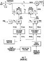
- FIG. 1 illustrates the basic elements of the main circuit and converter control structure for a grid-following double-fed wind turbine generator.
- the active power reference to the converter is developed by the energy source regulator, e.g., the turbine control portion of a wind turbine. This is conveyed as a torque reference, which represents the lesser of the maximum attainable power from the energy source at that instant, or a curtailment command from a higher-level grid controller.
- the converter control determines a current reference for the active component of current to achieve the desired torque.
- the double-fed wind turbine generator includes functions that manage the voltage and reactive power in a manner that results in a command for the reactive component of current.
- Wide-bandwidth current regulators then develop commands for voltage to be applied by the converters to the system, such that the actual currents closely track the commands.
- GMM grid-forming
- IBR inverter-based resources
- a grid-forming source must include the following basic functions: (1) support grid voltage and frequency for any current flow within the rating of the equipment, both real and reactive; (2) prevent operation beyond equipment voltage or current capability by allowing grid voltage or frequency to change rather than disconnecting equipment (disconnection is allowed only when voltage or frequency are outside of bounds established by the grid entity); (3) remain stable for any grid configuration or load characteristic, including serving an isolated load or connected with other grid-forming sources, and switching between such configurations; (4) share total load of the grid among other grid-forming sources connected to the grid; (5) ride through grid disturbances, both major and minor, and (6) meet requirements (1)-(5) without requiring fast communication with other control systems existing in the grid, or externally-created logic signals related to grid configuration changes.
- the grid-forming voltage-source is realized on the stator voltage for implementing grid forming control for a double-fed wind turbine generator using the stator voltage regulator.
- the stator voltage regulator 50 is configured to receive a higher level command (e.g., E I ) for magnitude of the stator voltage and a higher level command (e.g., ⁇ IT ) for angle of the stator voltage with respect to the phase-locked loop angle. Further, as shown, the stator voltage regulator 50 can then convert the voltage command(s) to a stator voltage command (e.g., VS_Cmd_xy) as shown at 52.
- a stator voltage command e.g., VS_Cmd_xy
- the stator voltage regulator 50 may then determine a magnetizing current feed forward signal (e.g., IM_FF_xy) as a function of the stator voltage command and a magnetizing admittance (e.g., jBmag 54), which may correspond to a magnetizing susceptance.
- a magnetizing current feed forward signal e.g., IM_FF_xy
- a magnetizing admittance e.g., jBmag 54
- the stator voltage regulator 50 may also receive a stator voltage feedback signal (e.g., VS_Fbk_xy) and, as shown at 62, determine a difference between the stator voltage feedback signal and the stator voltage command.
- a stator voltage feedback signal e.g., VS_Fbk_xy
- the stator voltage regulator 50 may also determine a magnetizing current correction signal (e.g., IM_Corr_xy) via a proportional-integral regulator 232.
- the stator voltage regulator 50 can then add the magnetizing current feed forward signal (e.g., IM_FF_xy) to the magnetizing current correction signal (IM_Corr_xy) from the power regulator to determine the magnetizing current command (e.g., IM_Cmd_xy).
- IM_FF_xy magnetizing current feed forward signal
- IM_Corr_xy magnetizing current correction signal
- the stator voltage regulator 50 may determine the rotor current command(s) (e.g., IR_Cmd_xy) as a function of the magnetizing current command (e.g., IM_Cmd_xy) and a stator current feedback signal (e.g., IS_Fbk_xy).
- the measured stator current signal may be fed into the rotor current command, as shown at 58, so as to substantially decouple a stator responsive stator voltage from one or more grid characteristics.
- the stator voltage regulator 50 may determine the rotor current command(s) by adding the magnetizing current command to the measured stator current feedback signal.
- a limiter 60 may place limits to the rotor current command as appropriate to respect equipment rating(s).
- non-linear magnetizing characteristics of the generator can be determined by electrical tests.
- Modern double-fed wind turbine generators have a wide range of ratings and generator types used for applications.
- identical generator designs practically exhibit different magnetizing characteristics due to nonuniformity in construction or materials. For these reasons, it is not practical to perform tests separately for each generator, nor is it practical to use the same characteristics for all generators.
- the present disclosure is directed to a method for controlling a wind turbine power system connected to an electrical grid.
- the wind turbine power system has a double-fed wind turbine generator coupled to a power converter having a line-side converter and a rotor-side converter coupled together via a DC link.
- the method includes determining, via a controller, at least one non-linear magnetizing parameter of the double-fed wind turbine generator.
- the method also includes developing, via the controller, a model of the at least one non-linear magnetizing parameter of the double-fed wind turbine generator.
- the method includes using, via the controller, the model in a stator voltage regulator of the double-fed wind turbine generator to provide grid-forming control of the double-fed wind turbine generator.
- the non-linear magnetizing parameter(s) is a magnetizing reactance.
- determining the non-linear magnetizing parameter(s) of the double-fed wind turbine generator may include (a) providing a plurality of data arrays comprising, at least, a data array of operating data points and a data array of non-linear magnetizing parameter data points, (b) enabling rotor control of the double-fed wind turbine generator with a stator switch open, (c) setting an operating set point of the double-fed wind turbine generator equal to a first operating data point in the data array of operating data points, (d) controlling the rotor-side converter to the operating set point and frequency for a time period, (e) collecting current and voltage feedbacks for the time period, and (f) calculating the at least one non-linear magnetizing parameter based on the current and voltage feedbacks for the time period.
- the method may also include (g) storing the operating set point and the at least one non-linear magnetizing parameter together in a data array, (h) setting the operating set point of the double-fed wind turbine generator equal to a remainder of the operating data points in the data array for subsequent time periods, and (i) repeating steps (d) through (g) for each of the operating data points in the data array for the subsequent time period.
- determining the non-linear magnetizing parameter(s) of the double-fed wind turbine generator may include averaging the collected current and voltage feedbacks for the time period to remove noise and calculating the non-linear magnetizing parameter(s) based on the averaged current and voltage feedbacks for the time period.
- the data array of operating data points may include, for example, flux data points or stator voltage data points.
- the data array of operating data points may include, at least, a range of expected operating data points that the double-fed wind turbine generator is expected to operate during normal operation.
- the data array of operating data points may include one or more additional data points to capture operating data points beyond the normal operation to estimate one or more characteristics of the double-fed wind turbine generator for at least one of abnormal conditions or temporary conditions.
- developing the model of the non-linear magnetizing parameter(s) of the double-fed wind turbine generator may include creating a saturation curve of the at least one non-linear magnetizing parameter versus the operating set point.
- the saturation curve may include a piecewise-linear curve fit.
- the method may include determining the non-linear magnetizing parameter(s) automatically using existing converter hardware and feedbacks.
- using the model in the stator voltage regulator of the double-fed wind turbine generator to provide grid-forming control of the double-fed wind turbine generator may include calculating an expected magnetizing reactance at a desired flux level using a stator flux command with slopes and y-intercepts of the saturation curve, calculating a magnetizing current feed forward signal based on the expected magnetizing reactance, calculating a magnetizing current command signal based on the magnetizing current feed forward signal and a magnetizing current correction signal, and calculating a rotor current command signals using the magnetizing current command signal and a stator current feedback signals.
- the present disclosure is directed to a system for controlling a wind turbine power system connected to an electrical grid.
- the wind turbine power system has a double-fed wind turbine generator coupled to a power converter having a line-side converter and a rotor-side converter coupled together via a DC link.
- the system includes a controller having at least one processor.
- the processor(s) is configured to perform a plurality of operations, including but not limited to determining at least one non-linear magnetizing reactance of the double-fed wind turbine generator, developing a model of the at least one non-linear magnetizing reactance of the double-fed wind turbine generator, and using the model in a stator voltage regulator of the double-fed wind turbine generator to provide grid-forming control of a double-fed wind turbine generator.
- grid-Forming control in double-fed wind-turbine generators can be achieved by controlling current through the magnetizing branch in the generator, thereby producing a voltage drop across the magnetizing impedance.
- a fixed control setting representing the magnetizing reactance can be used in the control, but this will result in errors in the voltage that is realized by the controller. The errors will change based on operating conditions due to the non-linear characteristics of the real magnetizing impedance.
- the desired voltage of the grid-forming system can be more accurately controlled if the non-linear magnetizing characteristic(s), such as the non-linear magnetizing reactance, is included as part of the control scheme.
- the non-linear magnetizing characteristic(s) can be estimated by controlling the rotor converter of the double-fed generator before the stator switch is closed to begin operation. By sweeping through a range of pre-defined operating points and taking measurements at each point, a model of the saturation curve can be constructed. This model can then be used for the grid-forming controls as further described herein.
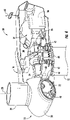
- FIG. 3 illustrates a perspective view of one embodiment of a wind turbine 10 according to the present disclosure.
- the wind turbine 10 generally includes a tower 12 extending from a support surface 14, a nacelle 16 mounted on the tower 12, and a rotor 18 coupled to the nacelle 16.
- the rotor 18 includes a rotatable hub 20 and at least one rotor blade 22 coupled to and extending outwardly from the hub 20.
- the rotor 18 includes three rotor blades 22.
- the rotor 18 may include more or less than three rotor blades 22.
- Each rotor blade 22 may be spaced about the hub 20 to facilitate rotating the rotor 18 to enable kinetic energy to be transferred from the wind into usable mechanical energy, and subsequently, electrical energy.
- the hub 20 may be rotatably coupled to an electric generator 24 ( FIG. 4 ) positioned within the nacelle 16 to permit electrical energy to be produced.
- the wind turbine 10 may also include a turbine controller 26 centralized within the nacelle 16. However, in other embodiments, the controller 26 may be located within any other component of the wind turbine 10 or at a location outside the wind turbine 10. Further, the controller 26 may be communicatively coupled to any number of the components of the wind turbine 10 in order to control the operation of such components and/or implement a corrective or control action. As such, the controller 26 may include a computer or other suitable processing unit. Thus, in several embodiments, the controller 26 may include suitable computer-readable instructions that, when implemented, configure the controller 26 to perform various different functions, such as receiving, transmitting and/or executing wind turbine control signals. Accordingly, the controller 26 may generally be configured to control the various operating modes (e.g., start-up or shut-down sequences), de-rating or up-rating the wind turbine, and/or individual components of the wind turbine 10.
- various operating modes e.g., start-up or shut-down sequences
- de-rating or up-rating the wind turbine and/or individual
- a generator 24 may be disposed within the nacelle 16 and supported atop a bedplate 46.
- the generator 24 may be coupled to the rotor 18 for producing electrical power from the rotational energy generated by the rotor 18.
- the rotor 18 may include a rotor shaft 34 coupled to the hub 20 for rotation therewith.
- the rotor shaft 34 may, in turn, be rotatably coupled to a generator shaft 36 of the generator 24 through a gearbox 38.
- the rotor shaft 34 may provide a low speed, high torque input to the gearbox 38 in response to rotation of the rotor blades 22 and the hub 20.
- the gearbox 38 may then be configured to convert the low speed, high torque input to a high speed, low torque output to drive the generator shaft 36 and, thus, the generator 24.
- the wind turbine 10 may also one or more pitch drive mechanisms 32 communicatively coupled to the turbine controller 26, with each pitch drive mechanisms(s) 32 being configured to rotate a pitch bearing 40 and thus the individual rotor blade(s) 22 about its respective pitch axis 28.
- the wind turbine 10 may include one or more yaw drive mechanisms 42 configured to change the angle of the nacelle 16 relative to the wind (e.g., by engaging a yaw bearing 44 of the wind turbine 10 that is arranged between the nacelle 16 and the tower 12 of the wind turbine 10).
- the wind turbine 10 may also include one or more sensors 66, 68 for monitoring various wind conditions of the wind turbine 10.
- the incoming wind direction 30, wind speed, or any other suitable wind condition near of the wind turbine 10 may be measured, such as through use of a suitable weather sensor 66.
- suitable weather sensors may include, for example, Light Detection and Ranging (“LIDAR”) devices, Sonic Detection and Ranging (“SODAR”) devices, anemometers, wind vanes, barometers, radar devices (such as Doppler radar devices) or any other sensing device which can provide wind directional information now known or later developed in the art.
- Still further sensors 68 may be utilized to measure additional operating parameters of the wind turbine 10, such as voltage, current, vibration, etc. as described herein.
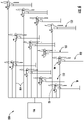
- FIGS. 5 and 6 schematic diagrams of certain embodiments of a wind turbine power system 100 is illustrated in accordance with aspects of the present disclosure.
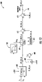
- FIG. 5 illustrates a schematic view of one embodiment of the wind turbine electrical power system 100 suitable for use with the wind turbine 10 shown in FIG. 3
- FIG. 6 illustrates a simplified equivalent circuit of the wind turbine electrical power system 100.
- the present disclosure will generally be described herein with reference to the wind turbine electrical power system 100 shown in FIGS. 5 and 6 , those of ordinary skill in the art, using the disclosures provided herein, should understand that aspects of the present disclosure may also be applicable in other power generation systems, and, as mentioned above, that the invention is not limited to wind turbine systems.
- the rotor 18 of the wind turbine 10 may, optionally, be coupled to the gearbox 38, which is, in turn, coupled to a generator 102, which may be a doubly fed induction generator (DFIG) as described herein.
- a generator 102 which may be a doubly fed induction generator (DFIG) as described herein.
- the DFIG 102 may be connected to a stator bus 104.
- a power converter 106 may be connected to the DFIG 102 via a rotor bus 108, and to the stator bus 104 via a line side bus 110.
- the stator bus 104 may provide an output multiphase power (e.g., three-phase power) from a stator of the DFIG 102
- the rotor bus 108 may provide an output multiphase power (e.g., three-phase power) from a rotor of the DFIG 102
- the power converter 106 may also include a rotor side converter (RSC) 112 and a line side converter (LSC) 114.
- the DFIG 102 is coupled via the rotor bus 108 to the RSC 112.
- the RSC 112 is coupled to the LSC 114 via a DC link 116 across which is a DC link capacitor 118.
- the LSC 114 is, in turn, coupled to the line side bus 110.
- the power converter 106 may also include a dynamic brake 105 as shown in FIG. 6 .
- the RSC 112 and the LSC 114 may be configured for normal operating mode in a three-phase, pulse width modulation (PWM) arrangement using one or more switching devices, such as insulated gate bipolar transistor (IGBT) switching elements.
- PWM pulse width modulation
- IGBT insulated gate bipolar transistor
- the power converter 106 may be coupled to a converter controller 120 in order to control the operation of the RSC 112 and/or the LSC 114 as described herein.
- the converter controller 120 may be configured as an interface between the power converter 106 and the turbine controller 26 and may include any number of control devices.
- various line contactors and circuit breakers including, for example, a grid breaker 122 may also be included for isolating the various components as necessary for normal operation of the DFIG 102 during connection to and disconnection from a load, such as the electrical grid 124.
- a system circuit breaker 126 may couple a system bus 128 to a transformer 130, which may be coupled to the electrical grid 124 via the grid breaker 122.
- fuses may replace some or all of the circuit breakers.
- alternating current power generated at the DFIG 102 by rotating the rotor 18 is provided to the electrical grid 124 via dual paths defined by the stator bus 104 and the rotor bus 108.
- sinusoidal multi-phase (e.g., three-phase) alternating current (AC) power is provided to the power converter 106.
- the RSC 112 converts the AC power provided from the rotor bus 108 into direct current (DC) power and provides the DC power to the DC link 116.
- switching elements e.g., IGBTs
- IGBTs switching elements used in the bridge circuits of the RSC 112 may be modulated to convert the AC power provided from the rotor bus 108 into DC power suitable for the DC link 116.
- the LSC 114 converts the DC power on the DC link 116 into AC output power suitable for the electrical grid 124.
- switching elements e.g., IGBTs
- IGBTs IGBTs
- the AC power from the power converter 106 can be combined with the power from the stator of DFIG 102 to provide multi-phase power (e.g., three-phase power) having a frequency maintained substantially at the frequency of the electrical grid 124 (e.g., 50 Hz or 60 Hz).
- various circuit breakers and switches such as grid breaker 122, system breaker 126, stator sync switch 132, converter breaker 134, and line contactor 136 may be included in the wind turbine power system 100 to connect or disconnect corresponding buses, for example, when current flow is excessive and may damage components of the wind turbine power system 100 or for other operational considerations. Additional protection components may also be included in the wind turbine power system 100.
- the power converter 106 may receive control signals from, for instance, the local control system 176 via the converter controller 120.
- the control signals may be based, among other things, on sensed states or operating characteristics of the wind turbine power system 100.
- the control signals provide for control of the operation of the power converter 106.
- feedback in the form of a sensed speed of the DFIG 102 may be used to control the conversion of the output power from the rotor bus 108 to maintain a proper and balanced multi-phase (e.g., three-phase) power supply.
- Other feedback from other sensors may also be used by the controller(s) 120, 26 to control the power converter 106, including, for example, stator and rotor bus voltages and current feedbacks.
- switching control signals e.g., gate timing commands for IGBTs
- stator synchronizing control signals e.g., stator synchronizing control signals
- circuit breaker signals may be generated.
- the power converter 106 also compensates or adjusts the frequency of the three-phase power from the rotor for changes, for example, in the wind speed at the hub 20 and the rotor blades 22. Therefore, mechanical and electrical rotor frequencies are decoupled and the electrical stator and rotor frequency matching is facilitated substantially independently of the mechanical rotor speed.
- the bi-directional characteristics of the power converter 106 facilitate feeding back at least some of the generated electrical power into generator rotor. More specifically, electrical power may be transmitted from the stator bus 104 to the line side bus 110 and subsequently through the line contactor 136 and into the power converter 106, specifically the LSC 114 which acts as a rectifier and rectifies the sinusoidal, three-phase AC power to DC power. The DC power is transmitted into the DC link 116.
- the DC link capacitor 118 facilitates mitigating DC link voltage amplitude variations by facilitating mitigation of a DC ripple sometimes associated with three-phase AC rectification.
- the DC power is subsequently transmitted to the RSC 112 that converts the DC electrical power to a three-phase, sinusoidal AC electrical power by adjusting voltages, currents, and frequencies. This conversion is monitored and controlled via the converter controller 120.
- the converted AC power is transmitted from the RSC 112 via the rotor bus 108 to the generator rotor. In this manner, generator reactive power control is facilitated by controlling rotor current and voltage.
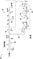
- the wind turbine power system 100 described herein may be part of a wind farm 150.
- the wind farm 150 may include a plurality of wind turbines 152, including the wind turbine 10 described above, and an overall farm-level controller 156.
- the wind farm 150 includes twelve wind turbines, including wind turbine 10.
- the wind farm 150 may include any other number of wind turbines, such as less than twelve wind turbines or greater than twelve wind turbines.
- the turbine controllers of the plurality of wind turbines 152 are communicatively coupled to the farm-level controller 156, e.g., through a wired connection, such as by connecting the turbine controller 26 through suitable communicative links 154 (e.g., a suitable cable).
- the turbine controllers may be communicatively coupled to the farm-level controller 156 through a wireless connection, such as by using any suitable wireless communications protocol known in the art.
- the farm-level controller 156 is configured to send and receive control signals to and from the various wind turbines 152, such as for example, distributing real and/or reactive power demands across the wind turbines 152 of the wind farm 150.
- the controller may include one or more processor(s) 158, computer, or other suitable processing unit and associated memory device(s) 160 that may include suitable computer-readable instructions that, when implemented, configure the controller to perform various different functions, such as receiving, transmitting and/or executing wind turbine control signals (e.g., performing the methods, steps, calculations and the like disclosed herein).
- processor(s) 158 computer, or other suitable processing unit and associated memory device(s) 160 that may include suitable computer-readable instructions that, when implemented, configure the controller to perform various different functions, such as receiving, transmitting and/or executing wind turbine control signals (e.g., performing the methods, steps, calculations and the like disclosed herein).
- the term "processor” refers not only to integrated circuits referred to in the art as being included in a computer, but also refers to a controller, a microcontroller, a microcomputer, a programmable logic controller (PLC), an application specific integrated circuit, and other programmable circuits.
- the memory device(s) 160 may generally comprise memory element(s) including, but not limited to, computer readable medium (e.g., random access memory (RAM)), computer readable non-volatile medium (e.g., a flash memory), a floppy disk, a compact disc-read only memory (CD-ROM), a magneto-optical disk (MOD), a digital versatile disc (DVD) and/or other suitable memory elements.
- RAM random access memory
- CD-ROM compact disc-read only memory
- MOD magneto-optical disk
- DVD digital versatile disc
- Such memory device(s) 160 may generally be configured to store suitable computer-readable instructions that, when implemented by the processor(s) 158, configure the controller to perform various functions as described herein. Additionally, the controller may also include a communications interface 162 to facilitate communications between the controller and the various components of the wind turbine 10. An interface can include one or more circuits, terminals, pins, contacts, conductors, or other components for sending and receiving control signals. Moreover, the controller may include a sensor interface 164 (e.g., one or more analog-to-digital converters) to permit signals transmitted from the sensors 66, 68 to be converted into signals that can be understood and processed by the processor(s) 58.
- a sensor interface 164 e.g., one or more analog-to-digital converters
- the power from the LSC 114 (P L ) can be approximated by assuming all the power from the rotor (P R ) of the DFIG 102 passes to the LSC 114, as given in Equation (2) below:
- P L ⁇ ⁇ P R ⁇ slip ⁇ Ps
- slip ⁇ elec ⁇ ⁇ rot / ⁇ elec
- ⁇ elec is the electrical frequency of the wind turbine power system 100
- ⁇ rot is the rotor speed of the rotor 18 of the wind turbine power system 100.
- the magnetizing reactance (Xm) of the DFIG 102 varies significantly with flux due to the non-linear permeability of the materials used in the construction of the generator iron core.
- Other factors that determine the magnetizing reactance are the stator and rotor winding turns, dimensions of stator and rotor, and material used in the construction. While these factors vary among different generator ratings and designs, the non-linear characteristic of the magnetizing reactance generally follows a characteristic curve as shown in FIG. 12 .
- FIG. 9 a schematic diagram of one embodiment of a system 200 for providing grid-forming control of a double-fed generator of a wind turbine according to the present disclosure is illustrated. More specifically, as shown, the system 200 may include many of the same features of FIG. 5 described herein, with components having the same reference characters representing like components. Further, as shown, the system 200 may include a control structure for controlling the line-side converter that is similar to the control structure shown in FIG. 5 .
- the LSC control structure may include a DC regulator 212 and a line current regulator 214.
- the DC regulator 212 is configured to generate line-side current commands for the line current regulator 214.
- the line current regulator 214 then generates line-side voltage commands for a modulator 218.
- the modulator 218 also receives an output (e.g., a phase-locked loop angle) from a phase-locked loop 216 to generate one or more gate pulses for the LSC 114.
- the phase-locked loop 216 typically generates its output using a voltage feedback signal.
- the system 200 may also include a control structure for controlling the RSC 112 using grid-forming characteristics.
- the system 200 may include a stator voltage regulator 206 for providing such grid-forming characteristics.
- the system 200 may include a grid voltage/VAR regulator 202, an inertial power regulator 204, a rotor current regulator 208, and a modulator 210.
- the grid voltage/VAR regulator 202 receives a voltage reference (e.g., VT_REF) from the farm-level controller 156 and generates a stator voltage magnitude command (e.g., VS_Mag_Cmd), whereas the inertial power regulator receives a power reference from the turbine controller 26 and generates a stator voltage angle command (e.g., VS_Angle_Cmd).
- VT_REF a voltage reference
- VS_Mag_Cmd stator voltage magnitude command
- VS_Angle_Cmd a stator voltage magnitude command
- the stator voltage regulator 206 determines one or more rotor current commands (e.g., IRCmdy and IRCmdx) as a function of the stator voltage magnitude command, the stator voltage angle command, and/or a stator current feedback signal 240 of the DFIG 102.
- the stator feedback current 240 is a strong indicator of the characteristics of the externally connected power system, i.e., the grid. Therefore, the stator feedback current 240 can be used as a feedback signal to decouple the response of stator voltage to variations to the nature of the grid.
- stator voltage regulator 206 Further details relating to the stator voltage regulator 206 are further explained and described in PCT/US2020/013787 entitled “System and Method for Providing Grid-Forming Control for a Doubly-Feb Wind Turbine Generator,” which is incorporated herein by reference in its entirety.
- FIGS. 10 through 13 generally describe methods 300, 400 and a system 600 for providing grid-forming control of a double-fed wind turbine generator, such as DFIG 102 according to the present disclosure.
- a flow diagram of one embodiment of a method 300 method for controlling a wind turbine power system connected to an electrical grid, such as wind turbine power system 100, according to the present disclosure is illustrated. It should be appreciated that the disclosed method 300 may be implemented with any suitable double-fed wind turbine generator having any suitable configuration.
- FIG. 10 depicts steps performed in a particular order for purposes of illustration and discussion, the methods discussed herein are not limited to any particular order or arrangement.
- One skilled in the art using the disclosures provided herein, will appreciate that various steps of the methods disclosed herein can be omitted, rearranged, combined, and/or adapted in various ways without deviating from the scope of the present disclosure.
- the method 300 includes determining, via a controller, at least one non-linear magnetizing parameter of the DFIG 102.
- the non-linear magnetizing parameter(s) may be a magnetizing reactance Xm.
- various tests can be performed on the DFIG 102 to measure the non-linear magnetizing characteristics.
- such tests may include a no-load test.
- this test may include running the DFIG 102 with zero slip and exciting the DFIG 102 through the stator winding. Measurements for a range of applied stator voltage levels while measuring stator current can be used to estimate the saturation curve.
- the magnetizing reactance can be estimated using voltage and current measurements using Equation (5) below:
- Xm Flux / Is where the rotor current is assumed to be zero at zero slip and the flux can be calculated from the stator voltage using Equation (6) below:
- Flux Vs / ⁇ elec where ⁇ elec is the frequency of the voltage and Equations (5) and (6) reflect per-unit quantities.
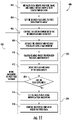
- the non-linear magnetizing characteristic(s) can be estimated by controlling the rotor converter of the DFIG 102 before the stator switch is closed to begin operation. All quantities are in per-unit. More particularly, as shown, the method 400 begins at 402 with (a) providing a plurality of data arrays including, for example, at least, a data array of operating data points and a data array of non-linear magnetizing parameter data points.
- the data array of operating data points may include, for example, flux data points or stator voltage data points.
- the data array of operating data points may include, at least, a range of expected operating data points that the DFIG 102 is expected to operate during normal operation.
- the data array of operating data points may include one or more additional data points to capture operating data points beyond the normal operation to estimate one or more characteristics of the DFIG 102 for at least one of abnormal conditions or temporary conditions.
- the method 400 may also include enabling rotor control of the DFIG 102 with the stator sync switch 132 open.
- the method 400 includes (c) setting an operating set point of the DFIG 102 equal to a first operating data point in the data array of operating data points.
- the method 400 includes (d) controlling the rotor-side converter to the operating set point and frequency for a time period (e.g., such as the desired flux and frequency).
- the method 400 may also include (e) collecting current and voltage feedbacks for the time period. More particularly, as shown at (408), the method 400 may include averaging the collected current and voltage feedbacks for the time period to remove noise and calculating the non-linear magnetizing parameter(s) based on the averaged current and voltage feedbacks for the time period. Thus, as shown at (410), the method 400 includes (f) calculating the non-linear magnetizing parameter(s) based on the current and voltage feedbacks for the time period.
- the averaged values can then be used to calculate the magnetizing reactance using Equation (8) below:
- FluxX _ Fbk _ Avg + jFluxY _ Fbk _ Avg Vsx _ Fbk _ Avg + j * Vsy _ Fbk _ Avg / j * ⁇ elec
- the method 400 may also include (g) storing the operating set point and the non-linear magnetizing parameter(s) together in a data array.
- the averaged values of flux and current may be stored together with a calculated value of Xm.
- the method 400 also includes (h) setting the operating set point of the DFIG 102 equal to a remainder of the operating data points in the data array for subsequent time periods.
- the method 400 includes determining whether the method 400 has gone through each of the operating data points in the data array. More specifically, the method 400 includes (i) repeating any of the method steps described herein for each of the operating data points in the data array for subsequent time periods. If not, the method 400 continues as shown via arrow 420 repeating the steps need to complete the data array. Once all of the operating data points have been tested, the method 400 proceeds to step (416).
- the data collected from the aforementioned test may be post-processed and analyzed separately after the testing is carried out to determine the generator magnetizing characteristics.
- Modern double-fed wind turbines have a wide range of ratings and generator types used for applications. Additionally, identical generator designs practically exhibit different magnetizing characteristics due to nonuniformity in construction or materials. For these reasons, it is not practical to perform these tests separately for each generator, nor is it practical to use the same curve for all generators. Therefore, the methods described herein for estimating the magnetizing reactance automatically use the existing converter hardware and feedbacks for use in grid-forming converter control systems in the DFIG 102.
- the method 300 also includes developing, via the controller, a model of the non-linear magnetizing parameter(s) of the DFIG 102.
- developing the model of the non-linear magnetizing parameter(s) of the DFIG 102 may include creating a saturation curve 500 of the non-linear magnetizing parameter(s) versus the operating set point.
- the saturation curve 500 may include a piecewise-linear curve fit.
- the method 400 may include collecting the measurements at a range of stator voltage levels allows for construction of the non-linear magnetizing parameter(s) (e.g., the magnetizing reactance Xm) versus flux curve similar to that shown in FIG. 12 .
- the method 400 may include fitting the operating data points to a curve fit, e.g., using an interpolation algorithm.
- a piecewise-linear curve fit can be obtained by connecting two consecutive points on the curve.
- Each linear segment can be approximated by a straight line with slope (Slp) and y-intercept (Icpt), using for example, Equations (11) and (12) below:
- Slp 1 Xm 2 ⁇ Xm 1 / F 2 ⁇ F 1
- Icpt 1 Xm 1 ⁇ Slp 1 * F 1
- this collection of slopes and y-intercepts calculated based on measured data can be used to model the magnetizing characteristic for the voltage regulator in the grid-forming control.
- the method 300 includes using, via the controller, the model in a stator voltage regulator of the double-fed wind turbine generator to provide grid-forming control of the DFIG 102. More particularly, in an embodiment, integration of the magnetizing characteristic model (e.g., the saturation curve 500) into a grid forming stator voltage regulator 600 is shown in FIG. 13 .
- the stator voltage regulator 600 is configured to receive a higher level command (e.g., E I ) for magnitude of the stator voltage and a higher level command (e.g., ⁇ IT ) for angle of the stator voltage with respect to the phase-locked loop angle.
- stator voltage commands are converted to flux commands using a signal indicating electrical frequency ⁇ elec .
- the signals drawn in bold represent two-dimensional complex phasors.
- the stator voltage regulator 600 is configured to convert the voltage command(s) to a stator flux command (e.g., ⁇ S_Cmd_xy) as shown at 602.
- the stator voltage regulator 600 may determine or otherwise calculate an expected magnetizing reactance Xmag at a desired flux level using the stator flux command with the slopes and the y-intercepts of the saturation curve 500.
- the stator voltage regulator 600 may then determine a magnetizing current feed forward signal (e.g., IM_FF_xy) as a function of the stator flux command and a function of the magnetizing reactance Xmag (e.g., 1/Xmag) from the saturation curve 500.
- IM_FF_xy magnetizing current feed forward signal
- Xmag magnetizing reactance
- the stator voltage regulator 600 may also receive a stator voltage feedback signal (e.g., VS_Fbk_xy) and convert the stator voltage feedback signal into a flux feedback signal as shown at 606 using the electrical frequency ⁇ elec . Thus, as shown at 608, the stator voltage regulator 600 may then determine a difference between the flux feedback signal and the stator flux command. Further, as shown, the stator voltage regulator 600 may also determine a magnetizing current correction signal (e.g., IM_Corr_xy) via a proportional-integral regulator 610.
- a stator voltage feedback signal e.g., VS_Fbk_xy
- the stator voltage regulator 600 can then add the magnetizing current feed forward signal (e.g., IM_FF_xy) to the magnetizing current correction signal (IM_Corr_xy) from the power regulator to determine the magnetizing current command (e.g., IM_Cmd_xy).
- IM_FF_xy magnetizing current feed forward signal
- IM_Corr_xy magnetizing current correction signal
- the stator voltage regulator 600 may determine the rotor current command(s) (e.g., IR_Cmd_xy) as a function of the magnetizing current command (e.g., IM_Cmd_xy) and a stator current feedback signal (e.g., IS_Fbk_xy). More specifically, in particular embodiments, as shown, the stator voltage regulator 600 may determine the rotor current command(s) by adding the magnetizing current command to the measured stator current feedback signal. In addition, as shown, a limiter 616 may place limits to the rotor current command as appropriate to respect equipment rating(s).
- a limiter 616 may place limits to the rotor current command as appropriate to respect equipment rating(s).
Landscapes
- Engineering & Computer Science (AREA)
- Power Engineering (AREA)
- Life Sciences & Earth Sciences (AREA)
- Sustainable Development (AREA)
- Sustainable Energy (AREA)
- Chemical & Material Sciences (AREA)
- Combustion & Propulsion (AREA)
- Mechanical Engineering (AREA)
- General Engineering & Computer Science (AREA)
- Control Of Eletrric Generators (AREA)
- Wind Motors (AREA)
Abstract
Description
- The present disclosure relates generally to double-fed wind turbine generators and, more particularly, to systems and methods for providing grid-forming control of a double-fed wind turbine generator.
- Wind power is considered one of the cleanest, most environmentally friendly energy sources presently available, and wind turbines have gained increased attention in this regard. A modern wind turbine typically includes a tower, generator, gearbox, nacelle, and one or more rotor blades. The rotor blades capture kinetic energy of wind using known airfoil principles. For example, rotor blades typically have the cross-sectional profile of an airfoil such that, during operation, air flows over the blade producing a pressure difference between the sides. Consequently, a lift force, which is directed from a pressure side towards a suction side, acts on the blade. The lift force generates torque on the main rotor shaft, which is typically geared to a generator for producing electricity.
- Wind turbines can be distinguished in two types: fixed speed and variable speed turbines. Conventionally, variable speed wind turbines are controlled as current sources connected to a power grid. In other words, the variable speed wind turbines rely on a grid frequency detected by a phase locked loop (PLL) as a reference and inject a specified amount of current into the grid. The conventional current source control of the wind turbines is based on the assumptions that the grid voltage waveforms are fundamental voltage waveforms with fixed frequency and magnitude and that the penetration of wind power into the grid is low enough so as to not cause disturbances to the grid voltage magnitude and frequency. Thus, the wind turbines simply inject the specified current into the grid based on the fundamental voltage waveforms. However, with the rapid growth of the wind power, wind power penetration into some grids has increased to the point where wind turbine generators have a significant impact on the grid voltage and frequency. When wind turbines are located in a weak grid, wind turbine power fluctuations may lead to an increase in magnitude and frequency variations in the grid voltage. These fluctuations may adversely affect the performance and stability of the PLL and wind turbine current control.
- Furthermore, many existing renewable generation converters, such as double-fed wind turbine generators, operate in a "grid-following" mode. Grid-following type devices utilize fast current-regulation loops to control active and reactive power exchanged with the grid. More specifically,
FIG. 1 illustrates the basic elements of the main circuit and converter control structure for a grid-following double-fed wind turbine generator. As shown, the active power reference to the converter is developed by the energy source regulator, e.g., the turbine control portion of a wind turbine. This is conveyed as a torque reference, which represents the lesser of the maximum attainable power from the energy source at that instant, or a curtailment command from a higher-level grid controller. The converter control then determines a current reference for the active component of current to achieve the desired torque. Accordingly, the double-fed wind turbine generator includes functions that manage the voltage and reactive power in a manner that results in a command for the reactive component of current. Wide-bandwidth current regulators then develop commands for voltage to be applied by the converters to the system, such that the actual currents closely track the commands. - Alternatively, grid-forming (GFM) inverter-based resources (IBR) act as a voltage source behind an impedance and provide a voltage-source characteristic, where the angle and magnitude of the voltage are controlled to achieve the regulation functions needed by the grid. In particular, with this structure, current will flow according to the demands of the grid, while the converter contributes to establishing a voltage and frequency for the grid. This characteristic is comparable to conventional generators based on a turbine driving a synchronous machine. Thus, a grid-forming source must include the following basic functions: (1) support grid voltage and frequency for any current flow within the rating of the equipment, both real and reactive; (2) prevent operation beyond equipment voltage or current capability by allowing grid voltage or frequency to change rather than disconnecting equipment (disconnection is allowed only when voltage or frequency are outside of bounds established by the grid entity); (3) remain stable for any grid configuration or load characteristic, including serving an isolated load or connected with other grid-forming sources, and switching between such configurations; (4) share total load of the grid among other grid-forming sources connected to the grid; (5) ride through grid disturbances, both major and minor, and (6) meet requirements (1)-(5) without requiring fast communication with other control systems existing in the grid, or externally-created logic signals related to grid configuration changes.
- The basic control structure to achieve the above grid-forming objectives was developed and field-proven for battery systems in the early 1990's (see e.g.,
United States Patent No.: 5,798,633 entitled "Battery Energy Storage Power Conditioning System"). Applications to full-converter wind generators and solar generators are disclosed inUnited States Patent No.: 7,804,184 entitled "System and Method for Control of a Grid Connected Power Generating System," andUnited States Patent No.: 9,270,194 PCT/US2020/013787 entitled "System and Method for Providing Grid-Forming Control for a Doubly-Feb Wind Turbine Generator." - In particular, as shown in
FIG. 2 , the grid-forming voltage-source is realized on the stator voltage for implementing grid forming control for a double-fed wind turbine generator using the stator voltage regulator. More specifically, as shown, thestator voltage regulator 50 is configured to receive a higher level command (e.g., EI) for magnitude of the stator voltage and a higher level command (e.g., δIT) for angle of the stator voltage with respect to the phase-locked loop angle. Further, as shown, thestator voltage regulator 50 can then convert the voltage command(s) to a stator voltage command (e.g., VS_Cmd_xy) as shown at 52. Thestator voltage regulator 50 may then determine a magnetizing current feed forward signal (e.g., IM_FF_xy) as a function of the stator voltage command and a magnetizing admittance (e.g., jBmag 54), which may correspond to a magnetizing susceptance. As such, the magnetizing current feed forward signal is configured to facilitate a rapid response of stator voltage to the stator voltage command. - In addition, as shown, the
stator voltage regulator 50 may also receive a stator voltage feedback signal (e.g., VS_Fbk_xy) and, as shown at 62, determine a difference between the stator voltage feedback signal and the stator voltage command. Thus, in an embodiment, as shown, thestator voltage regulator 50 may also determine a magnetizing current correction signal (e.g., IM_Corr_xy) via a proportional-integral regulator 232. Accordingly, as shown at 56, thestator voltage regulator 50 can then add the magnetizing current feed forward signal (e.g., IM_FF_xy) to the magnetizing current correction signal (IM_Corr_xy) from the power regulator to determine the magnetizing current command (e.g., IM_Cmd_xy). - Furthermore, as shown at 58, the
stator voltage regulator 50 may determine the rotor current command(s) (e.g., IR_Cmd_xy) as a function of the magnetizing current command (e.g., IM_Cmd_xy) and a stator current feedback signal (e.g., IS_Fbk_xy). Thus, in an embodiment, the measured stator current signal may be fed into the rotor current command, as shown at 58, so as to substantially decouple a stator responsive stator voltage from one or more grid characteristics. More specifically, in particular embodiments, as shown, thestator voltage regulator 50 may determine the rotor current command(s) by adding the magnetizing current command to the measured stator current feedback signal. In addition, as shown, alimiter 60 may place limits to the rotor current command as appropriate to respect equipment rating(s). - In such systems, non-linear magnetizing characteristics of the generator can be determined by electrical tests. Modern double-fed wind turbine generators have a wide range of ratings and generator types used for applications. Additionally, identical generator designs practically exhibit different magnetizing characteristics due to nonuniformity in construction or materials. For these reasons, it is not practical to perform tests separately for each generator, nor is it practical to use the same characteristics for all generators.
- Accordingly, systems and methods for estimating the magnetizing reactance automatically using the existing converter hardware and feedbacks would be beneficial for use in grid-forming converter control systems in double-fed wind-turbine generators.
- Aspects and advantages of the invention will be set forth in part in the following description, or may be obvious from the description, or may be learned through practice of the invention.
- In one aspect, the present disclosure is directed to a method for controlling a wind turbine power system connected to an electrical grid. The wind turbine power system has a double-fed wind turbine generator coupled to a power converter having a line-side converter and a rotor-side converter coupled together via a DC link. The method includes determining, via a controller, at least one non-linear magnetizing parameter of the double-fed wind turbine generator. The method also includes developing, via the controller, a model of the at least one non-linear magnetizing parameter of the double-fed wind turbine generator. Further, the method includes using, via the controller, the model in a stator voltage regulator of the double-fed wind turbine generator to provide grid-forming control of the double-fed wind turbine generator.
- In an embodiment, the non-linear magnetizing parameter(s) is a magnetizing reactance.
- In another embodiment, determining the non-linear magnetizing parameter(s) of the double-fed wind turbine generator may include (a) providing a plurality of data arrays comprising, at least, a data array of operating data points and a data array of non-linear magnetizing parameter data points, (b) enabling rotor control of the double-fed wind turbine generator with a stator switch open, (c) setting an operating set point of the double-fed wind turbine generator equal to a first operating data point in the data array of operating data points, (d) controlling the rotor-side converter to the operating set point and frequency for a time period, (e) collecting current and voltage feedbacks for the time period, and (f) calculating the at least one non-linear magnetizing parameter based on the current and voltage feedbacks for the time period.
- In further embodiments, the method may also include (g) storing the operating set point and the at least one non-linear magnetizing parameter together in a data array, (h) setting the operating set point of the double-fed wind turbine generator equal to a remainder of the operating data points in the data array for subsequent time periods, and (i) repeating steps (d) through (g) for each of the operating data points in the data array for the subsequent time period.
- In additional embodiments, determining the non-linear magnetizing parameter(s) of the double-fed wind turbine generator may include averaging the collected current and voltage feedbacks for the time period to remove noise and calculating the non-linear magnetizing parameter(s) based on the averaged current and voltage feedbacks for the time period.
- In several embodiments, the data array of operating data points may include, for example, flux data points or stator voltage data points.
- In particular embodiments, the data array of operating data points may include, at least, a range of expected operating data points that the double-fed wind turbine generator is expected to operate during normal operation. In another embodiment, the data array of operating data points may include one or more additional data points to capture operating data points beyond the normal operation to estimate one or more characteristics of the double-fed wind turbine generator for at least one of abnormal conditions or temporary conditions.
- In certain embodiments, developing the model of the non-linear magnetizing parameter(s) of the double-fed wind turbine generator may include creating a saturation curve of the at least one non-linear magnetizing parameter versus the operating set point. For example, in an embodiment, the saturation curve may include a piecewise-linear curve fit.
- In an embodiment, the method may include determining the non-linear magnetizing parameter(s) automatically using existing converter hardware and feedbacks.
- In further embodiments, using the model in the stator voltage regulator of the double-fed wind turbine generator to provide grid-forming control of the double-fed wind turbine generator may include calculating an expected magnetizing reactance at a desired flux level using a stator flux command with slopes and y-intercepts of the saturation curve, calculating a magnetizing current feed forward signal based on the expected magnetizing reactance, calculating a magnetizing current command signal based on the magnetizing current feed forward signal and a magnetizing current correction signal, and calculating a rotor current command signals using the magnetizing current command signal and a stator current feedback signals.
- In another aspect, the present disclosure is directed to a system for controlling a wind turbine power system connected to an electrical grid. The wind turbine power system has a double-fed wind turbine generator coupled to a power converter having a line-side converter and a rotor-side converter coupled together via a DC link. The system includes a controller having at least one processor. The processor(s) is configured to perform a plurality of operations, including but not limited to determining at least one non-linear magnetizing reactance of the double-fed wind turbine generator, developing a model of the at least one non-linear magnetizing reactance of the double-fed wind turbine generator, and using the model in a stator voltage regulator of the double-fed wind turbine generator to provide grid-forming control of a double-fed wind turbine generator.
- It should be understood that the system may further include any of the additional features described herein.
- These and other features, aspects and advantages of the present invention will become better understood with reference to the following description and appended claims. The accompanying drawings, which are incorporated in and constitute a part of this specification, illustrate embodiments of the invention and, together with the description, serve to explain the principles of the invention.
- A full and enabling disclosure of the present invention, including the best mode thereof, directed to one of ordinary skill in the art, is set forth in the specification, which makes reference to the appended figures, in which:
-
FIG. 1 illustrates a one-line diagram of a double-fed wind turbine generator with structure of converter controls for grid-following application according to conventional construction; -
FIG. 2 illustrates a schematic diagram of one embodiment of a grid forming stator voltage regulator of a double-fed wind turbine generator according to the present disclosure; -
FIG. 3 illustrates a perspective view of one embodiment of a wind turbine according to the present disclosure; -
FIG. 4 illustrates a simplified, internal view of one embodiment of a nacelle according to the present disclosure; -
FIG. 5 illustrates a schematic view of one embodiment of a wind turbine electrical power system suitable for use with the wind turbine shown inFIG. 3 ; -
FIG. 6 illustrates a schematic view of one embodiment of a wind farm having a plurality of wind turbines according to the present disclosure; -
FIG. 7 illustrates a block diagram of one embodiment of a controller according to the present disclosure; -
FIG. 8 illustrates a simplified equivalent circuit of a wind turbine electrical power system according to the present disclosure; -
FIG. 9 illustrates a one-line diagram of a double-fed wind turbine generator with converter controls for grid-forming application according to the present disclosure; -
FIG. 10 illustrates a flow diagram of one embodiment of method for controlling a wind turbine power system connected to an electrical grid according to the present disclosure; -
FIG. 11 illustrates a flow diagram of another embodiment of method for controlling a wind turbine power system connected to an electrical grid according to the present disclosure; -
FIG. 12 illustrates a graph of one embodiment of a typical saturation curve of magnetizing reactance (y-axis) versus flux (x-axis) according to the present disclosure; and -
FIG. 13 illustrates a schematic diagram of one embodiment of a grid-forming stator voltage regulator using a model of generator magnetizing saturation. - Reference now will be made in detail to embodiments of the invention, one or more examples of which are illustrated in the drawings. Each example is provided by way of explanation of the invention, not limitation of the invention. In fact, it will be apparent to those skilled in the art that various modifications and variations can be made in the present invention without departing from the scope or spirit of the invention. For instance, features illustrated or described as part of one embodiment can be used with another embodiment to yield a still further embodiment. Thus, it is intended that the present invention covers such modifications and variations as come within the scope of the appended claims and their equivalents.
- In general, the present disclosure is directed to systems and method for providing grid-forming control for a double-fed wind-turbine generator. More particularly, in certain embodiments, grid-Forming control in double-fed wind-turbine generators can be achieved by controlling current through the magnetizing branch in the generator, thereby producing a voltage drop across the magnetizing impedance. A fixed control setting representing the magnetizing reactance can be used in the control, but this will result in errors in the voltage that is realized by the controller. The errors will change based on operating conditions due to the non-linear characteristics of the real magnetizing impedance. Accordingly, the desired voltage of the grid-forming system can be more accurately controlled if the non-linear magnetizing characteristic(s), such as the non-linear magnetizing reactance, is included as part of the control scheme. For example, in an embodiment, the non-linear magnetizing characteristic(s) can be estimated by controlling the rotor converter of the double-fed generator before the stator switch is closed to begin operation. By sweeping through a range of pre-defined operating points and taking measurements at each point, a model of the saturation curve can be constructed. This model can then be used for the grid-forming controls as further described herein.
- Referring now to the drawings,
FIG. 3 illustrates a perspective view of one embodiment of awind turbine 10 according to the present disclosure. As shown, thewind turbine 10 generally includes atower 12 extending from asupport surface 14, anacelle 16 mounted on thetower 12, and arotor 18 coupled to thenacelle 16. Therotor 18 includes arotatable hub 20 and at least onerotor blade 22 coupled to and extending outwardly from thehub 20. For example, in the illustrated embodiment, therotor 18 includes threerotor blades 22. However, in an alternative embodiment, therotor 18 may include more or less than threerotor blades 22. Eachrotor blade 22 may be spaced about thehub 20 to facilitate rotating therotor 18 to enable kinetic energy to be transferred from the wind into usable mechanical energy, and subsequently, electrical energy. For instance, thehub 20 may be rotatably coupled to an electric generator 24 (FIG. 4 ) positioned within thenacelle 16 to permit electrical energy to be produced. - The
wind turbine 10 may also include aturbine controller 26 centralized within thenacelle 16. However, in other embodiments, thecontroller 26 may be located within any other component of thewind turbine 10 or at a location outside thewind turbine 10. Further, thecontroller 26 may be communicatively coupled to any number of the components of thewind turbine 10 in order to control the operation of such components and/or implement a corrective or control action. As such, thecontroller 26 may include a computer or other suitable processing unit. Thus, in several embodiments, thecontroller 26 may include suitable computer-readable instructions that, when implemented, configure thecontroller 26 to perform various different functions, such as receiving, transmitting and/or executing wind turbine control signals. Accordingly, thecontroller 26 may generally be configured to control the various operating modes (e.g., start-up or shut-down sequences), de-rating or up-rating the wind turbine, and/or individual components of thewind turbine 10. - Referring now to
FIG. 4 , a simplified, internal view of one embodiment of thenacelle 16 of thewind turbine 10 shown inFIG. 1 is illustrated. As shown, agenerator 24 may be disposed within thenacelle 16 and supported atop abedplate 46. In general, thegenerator 24 may be coupled to therotor 18 for producing electrical power from the rotational energy generated by therotor 18. For example, as shown in the illustrated embodiment, therotor 18 may include arotor shaft 34 coupled to thehub 20 for rotation therewith. Therotor shaft 34 may, in turn, be rotatably coupled to agenerator shaft 36 of thegenerator 24 through agearbox 38. As is generally understood, therotor shaft 34 may provide a low speed, high torque input to thegearbox 38 in response to rotation of therotor blades 22 and thehub 20. Thegearbox 38 may then be configured to convert the low speed, high torque input to a high speed, low torque output to drive thegenerator shaft 36 and, thus, thegenerator 24. - The
wind turbine 10 may also one or morepitch drive mechanisms 32 communicatively coupled to theturbine controller 26, with each pitch drive mechanisms(s) 32 being configured to rotate apitch bearing 40 and thus the individual rotor blade(s) 22 about itsrespective pitch axis 28. In addition, as shown, thewind turbine 10 may include one or moreyaw drive mechanisms 42 configured to change the angle of thenacelle 16 relative to the wind (e.g., by engaging a yaw bearing 44 of thewind turbine 10 that is arranged between thenacelle 16 and thetower 12 of the wind turbine 10). - In addition, the
wind turbine 10 may also include one ormore sensors wind turbine 10. For example, theincoming wind direction 30, wind speed, or any other suitable wind condition near of thewind turbine 10 may be measured, such as through use of asuitable weather sensor 66. Suitable weather sensors may include, for example, Light Detection and Ranging ("LIDAR") devices, Sonic Detection and Ranging ("SODAR") devices, anemometers, wind vanes, barometers, radar devices (such as Doppler radar devices) or any other sensing device which can provide wind directional information now known or later developed in the art. Stillfurther sensors 68 may be utilized to measure additional operating parameters of thewind turbine 10, such as voltage, current, vibration, etc. as described herein. - Referring now to
FIGS. 5 and6 , schematic diagrams of certain embodiments of a windturbine power system 100 is illustrated in accordance with aspects of the present disclosure. In particular,FIG. 5 illustrates a schematic view of one embodiment of the wind turbineelectrical power system 100 suitable for use with thewind turbine 10 shown inFIG. 3 , whereasFIG. 6 illustrates a simplified equivalent circuit of the wind turbineelectrical power system 100. Although the present disclosure will generally be described herein with reference to the wind turbineelectrical power system 100 shown inFIGS. 5 and6 , those of ordinary skill in the art, using the disclosures provided herein, should understand that aspects of the present disclosure may also be applicable in other power generation systems, and, as mentioned above, that the invention is not limited to wind turbine systems. - In the embodiment of
FIG. 5 and as mentioned, therotor 18 of the wind turbine 10 (FIG. 3 ) may, optionally, be coupled to thegearbox 38, which is, in turn, coupled to agenerator 102, which may be a doubly fed induction generator (DFIG) as described herein. As shown inFIGS. 5 and6 , theDFIG 102 may be connected to astator bus 104. Further, as shown inFIGS. 5 and6 , apower converter 106 may be connected to theDFIG 102 via arotor bus 108, and to thestator bus 104 via aline side bus 110. As such, thestator bus 104 may provide an output multiphase power (e.g., three-phase power) from a stator of theDFIG 102, and therotor bus 108 may provide an output multiphase power (e.g., three-phase power) from a rotor of theDFIG 102. Thepower converter 106 may also include a rotor side converter (RSC) 112 and a line side converter (LSC) 114. TheDFIG 102 is coupled via therotor bus 108 to theRSC 112. Additionally, theRSC 112 is coupled to theLSC 114 via aDC link 116 across which is aDC link capacitor 118. TheLSC 114 is, in turn, coupled to theline side bus 110. Thepower converter 106 may also include adynamic brake 105 as shown inFIG. 6 . - The
RSC 112 and theLSC 114 may be configured for normal operating mode in a three-phase, pulse width modulation (PWM) arrangement using one or more switching devices, such as insulated gate bipolar transistor (IGBT) switching elements. In addition, as shown inFIG. 5 , thepower converter 106 may be coupled to aconverter controller 120 in order to control the operation of theRSC 112 and/or theLSC 114 as described herein. It should be noted that theconverter controller 120 may be configured as an interface between thepower converter 106 and theturbine controller 26 and may include any number of control devices. - In typical configurations, various line contactors and circuit breakers including, for example, a
grid breaker 122 may also be included for isolating the various components as necessary for normal operation of theDFIG 102 during connection to and disconnection from a load, such as theelectrical grid 124. For example, asystem circuit breaker 126 may couple asystem bus 128 to atransformer 130, which may be coupled to theelectrical grid 124 via thegrid breaker 122. In alternative embodiments, fuses may replace some or all of the circuit breakers. - In operation, alternating current power generated at the
DFIG 102 by rotating therotor 18 is provided to theelectrical grid 124 via dual paths defined by thestator bus 104 and therotor bus 108. On the rotor-bus side, sinusoidal multi-phase (e.g., three-phase) alternating current (AC) power is provided to thepower converter 106. TheRSC 112 converts the AC power provided from therotor bus 108 into direct current (DC) power and provides the DC power to theDC link 116. As is generally understood, switching elements (e.g., IGBTs) used in the bridge circuits of theRSC 112 may be modulated to convert the AC power provided from therotor bus 108 into DC power suitable for theDC link 116. - In addition, the
LSC 114 converts the DC power on the DC link 116 into AC output power suitable for theelectrical grid 124. In particular, switching elements (e.g., IGBTs) used in bridge circuits of theLSC 114 can be modulated to convert the DC power on the DC link 116 into AC power on theline side bus 110. The AC power from thepower converter 106 can be combined with the power from the stator ofDFIG 102 to provide multi-phase power (e.g., three-phase power) having a frequency maintained substantially at the frequency of the electrical grid 124 (e.g., 50 Hz or 60 Hz). - Additionally, as shown in
FIG. 5 , various circuit breakers and switches, such asgrid breaker 122,system breaker 126,stator sync switch 132,converter breaker 134, andline contactor 136 may be included in the windturbine power system 100 to connect or disconnect corresponding buses, for example, when current flow is excessive and may damage components of the windturbine power system 100 or for other operational considerations. Additional protection components may also be included in the windturbine power system 100. - Moreover, the
power converter 106 may receive control signals from, for instance, the local control system 176 via theconverter controller 120. The control signals may be based, among other things, on sensed states or operating characteristics of the windturbine power system 100. Typically, the control signals provide for control of the operation of thepower converter 106. For example, feedback in the form of a sensed speed of theDFIG 102 may be used to control the conversion of the output power from therotor bus 108 to maintain a proper and balanced multi-phase (e.g., three-phase) power supply. Other feedback from other sensors may also be used by the controller(s) 120, 26 to control thepower converter 106, including, for example, stator and rotor bus voltages and current feedbacks. Using the various forms of feedback information, switching control signals (e.g., gate timing commands for IGBTs), stator synchronizing control signals, and circuit breaker signals may be generated. - The
power converter 106 also compensates or adjusts the frequency of the three-phase power from the rotor for changes, for example, in the wind speed at thehub 20 and therotor blades 22. Therefore, mechanical and electrical rotor frequencies are decoupled and the electrical stator and rotor frequency matching is facilitated substantially independently of the mechanical rotor speed. - Under some states, the bi-directional characteristics of the
power converter 106, and specifically, the bi-directional characteristics of theLSC 114 andRSC 112, facilitate feeding back at least some of the generated electrical power into generator rotor. More specifically, electrical power may be transmitted from thestator bus 104 to theline side bus 110 and subsequently through theline contactor 136 and into thepower converter 106, specifically theLSC 114 which acts as a rectifier and rectifies the sinusoidal, three-phase AC power to DC power. The DC power is transmitted into theDC link 116. TheDC link capacitor 118 facilitates mitigating DC link voltage amplitude variations by facilitating mitigation of a DC ripple sometimes associated with three-phase AC rectification. - The DC power is subsequently transmitted to the
RSC 112 that converts the DC electrical power to a three-phase, sinusoidal AC electrical power by adjusting voltages, currents, and frequencies. This conversion is monitored and controlled via theconverter controller 120. The converted AC power is transmitted from theRSC 112 via therotor bus 108 to the generator rotor. In this manner, generator reactive power control is facilitated by controlling rotor current and voltage. - Referring now to
FIG. 6 , the windturbine power system 100 described herein may be part of awind farm 150. As shown, thewind farm 150 may include a plurality ofwind turbines 152, including thewind turbine 10 described above, and an overall farm-level controller 156. For example, as shown in the illustrated embodiment, thewind farm 150 includes twelve wind turbines, includingwind turbine 10. However, in other embodiments, thewind farm 150 may include any other number of wind turbines, such as less than twelve wind turbines or greater than twelve wind turbines. In one embodiment, the turbine controllers of the plurality ofwind turbines 152 are communicatively coupled to the farm-level controller 156, e.g., through a wired connection, such as by connecting theturbine controller 26 through suitable communicative links 154 (e.g., a suitable cable). Alternatively, the turbine controllers may be communicatively coupled to the farm-level controller 156 through a wireless connection, such as by using any suitable wireless communications protocol known in the art. In further embodiments, the farm-level controller 156 is configured to send and receive control signals to and from thevarious wind turbines 152, such as for example, distributing real and/or reactive power demands across thewind turbines 152 of thewind farm 150. - Referring now to
FIG. 7 , a block diagram of one embodiment of suitable components that may be included within the controller (such as any one of theturbine controller 26, theconverter controller 120, and/or the farm-level controller 156 described herein) in accordance with example aspects of the present disclosure is illustrated. As shown, the controller may include one or more processor(s) 158, computer, or other suitable processing unit and associated memory device(s) 160 that may include suitable computer-readable instructions that, when implemented, configure the controller to perform various different functions, such as receiving, transmitting and/or executing wind turbine control signals (e.g., performing the methods, steps, calculations and the like disclosed herein). - As used herein, the term "processor" refers not only to integrated circuits referred to in the art as being included in a computer, but also refers to a controller, a microcontroller, a microcomputer, a programmable logic controller (PLC), an application specific integrated circuit, and other programmable circuits. Additionally, the memory device(s) 160 may generally comprise memory element(s) including, but not limited to, computer readable medium (e.g., random access memory (RAM)), computer readable non-volatile medium (e.g., a flash memory), a floppy disk, a compact disc-read only memory (CD-ROM), a magneto-optical disk (MOD), a digital versatile disc (DVD) and/or other suitable memory elements.
- Such memory device(s) 160 may generally be configured to store suitable computer-readable instructions that, when implemented by the processor(s) 158, configure the controller to perform various functions as described herein. Additionally, the controller may also include a
communications interface 162 to facilitate communications between the controller and the various components of thewind turbine 10. An interface can include one or more circuits, terminals, pins, contacts, conductors, or other components for sending and receiving control signals. Moreover, the controller may include a sensor interface 164 (e.g., one or more analog-to-digital converters) to permit signals transmitted from thesensors - Referring particularly to
FIG. 8 , as mentioned, a one-line circuit diagram of the windturbine power system 100 is illustrated. More particularly, as shown, the power (PT) generated by the windturbine power system 100 is the sum of the power from the generator stator (PS) and the LSC 114 (PL), given by Equation (1) below:
- Further, the power from the LSC 114 (PL) can be approximated by assuming all the power from the rotor (PR) of the
DFIG 102 passes to theLSC 114, as given in Equation (2) below:

turbine power system 100, and ωrot is the rotor speed of therotor 18 of the windturbine power system 100. - Thus, in an embodiment, by combining the aforementioned relationships, the ratio of the stator power (Ps) to the total power (PT) can be expressed using Equation (4) below:

- Still further relationships illustrated in
FIG. 8 , such as voltage (V), current (I), and impedance (X), etc., will be described in more detail herein. - Furthermore, as shown in
FIG. 8 , the magnetizing reactance (Xm) of theDFIG 102 varies significantly with flux due to the non-linear permeability of the materials used in the construction of the generator iron core. Other factors that determine the magnetizing reactance are the stator and rotor winding turns, dimensions of stator and rotor, and material used in the construction. While these factors vary among different generator ratings and designs, the non-linear characteristic of the magnetizing reactance generally follows a characteristic curve as shown inFIG. 12 . - Referring now to
FIG. 9 , a schematic diagram of one embodiment of asystem 200 for providing grid-forming control of a double-fed generator of a wind turbine according to the present disclosure is illustrated. More specifically, as shown, thesystem 200 may include many of the same features ofFIG. 5 described herein, with components having the same reference characters representing like components. Further, as shown, thesystem 200 may include a control structure for controlling the line-side converter that is similar to the control structure shown inFIG. 5 . - Moreover, as shown, the LSC control structure may include a
DC regulator 212 and a linecurrent regulator 214. TheDC regulator 212 is configured to generate line-side current commands for the linecurrent regulator 214. The linecurrent regulator 214 then generates line-side voltage commands for amodulator 218. Themodulator 218 also receives an output (e.g., a phase-locked loop angle) from a phase-lockedloop 216 to generate one or more gate pulses for theLSC 114. The phase-lockedloop 216 typically generates its output using a voltage feedback signal. - Furthermore, as shown, the
system 200 may also include a control structure for controlling theRSC 112 using grid-forming characteristics. In particular, as shown inFIG. 9 , thesystem 200 may include astator voltage regulator 206 for providing such grid-forming characteristics. In addition, as shown, thesystem 200 may include a grid voltage/VAR regulator 202, aninertial power regulator 204, a rotorcurrent regulator 208, and amodulator 210. - In an embodiment, the grid voltage/
VAR regulator 202 receives a voltage reference (e.g., VT_REF) from the farm-level controller 156 and generates a stator voltage magnitude command (e.g., VS_Mag_Cmd), whereas the inertial power regulator receives a power reference from theturbine controller 26 and generates a stator voltage angle command (e.g., VS_Angle_Cmd). More specifically, in an embodiment, as shown, thestator voltage regulator 206 determines one or more rotor current commands (e.g., IRCmdy and IRCmdx) as a function of the stator voltage magnitude command, the stator voltage angle command, and/or a statorcurrent feedback signal 240 of theDFIG 102. It should be understood that the stator feedback current 240 is a strong indicator of the characteristics of the externally connected power system, i.e., the grid. Therefore, the stator feedback current 240 can be used as a feedback signal to decouple the response of stator voltage to variations to the nature of the grid. Further details relating to thestator voltage regulator 206 are further explained and described inPCT/US2020/013787 entitled "System and Method for Providing Grid-Forming Control for a Doubly-Feb Wind Turbine Generator," which is incorporated herein by reference in its entirety. - As mentioned, with grid-forming control, current changes rapidly when there are grid disturbances. Further, the control action is gradual to restore the steady-state operating conditions commanded by higher-level controls. The amount of current change is inversely related to the total impedance of the circuit. However, if the current exceeds limits, then the control responds rapidly to force the current to be within limits. This drastic nonlinearity can cause chaotic behavior when applied to a grid consisting of many other similar systems. Alternatively, if the current change is too small, then the grid-forming system will not contribute as much as it could to support the grid.
- Thus,
FIGS. 10 through 13 generally describemethods system 600 for providing grid-forming control of a double-fed wind turbine generator, such asDFIG 102 according to the present disclosure. Referring particularly toFIG. 10 , a flow diagram of one embodiment of amethod 300 method for controlling a wind turbine power system connected to an electrical grid, such as windturbine power system 100, according to the present disclosure is illustrated. It should be appreciated that the disclosedmethod 300 may be implemented with any suitable double-fed wind turbine generator having any suitable configuration. In addition, althoughFIG. 10 depicts steps performed in a particular order for purposes of illustration and discussion, the methods discussed herein are not limited to any particular order or arrangement. One skilled in the art, using the disclosures provided herein, will appreciate that various steps of the methods disclosed herein can be omitted, rearranged, combined, and/or adapted in various ways without deviating from the scope of the present disclosure. - As shown at (302), the
method 300 includes determining, via a controller, at least one non-linear magnetizing parameter of theDFIG 102. In an embodiment, the non-linear magnetizing parameter(s) may be a magnetizing reactance Xm. For example, in an embodiment, various tests can be performed on theDFIG 102 to measure the non-linear magnetizing characteristics. In one embodiment, such tests may include a no-load test. In such embodiments, this test may include running theDFIG 102 with zero slip and exciting theDFIG 102 through the stator winding. Measurements for a range of applied stator voltage levels while measuring stator current can be used to estimate the saturation curve. Furthermore, in such embodiments, the magnetizing reactance can be estimated using voltage and current measurements using Equation (5) below:

- Referring particularly to
FIG. 11 , as an example, a flow diagram of one embodiment of amethod 400 for estimating the non-linear magnetizing characteristic(s) is illustrated. As shown, the non-linear magnetizing characteristic(s) can be estimated by controlling the rotor converter of theDFIG 102 before the stator switch is closed to begin operation. All quantities are in per-unit. More particularly, as shown, themethod 400 begins at 402 with (a) providing a plurality of data arrays including, for example, at least, a data array of operating data points and a data array of non-linear magnetizing parameter data points. In several embodiments, the data array of operating data points may include, for example, flux data points or stator voltage data points. For example, in one embodiment, themethod 400 may include programming the controller with pre-defined arrays of test points for flux, given by Equation (7) below:
- Moreover, in particular embodiments, the data array of operating data points may include, at least, a range of expected operating data points that the
DFIG 102 is expected to operate during normal operation. In another embodiment, the data array of operating data points may include one or more additional data points to capture operating data points beyond the normal operation to estimate one or more characteristics of theDFIG 102 for at least one of abnormal conditions or temporary conditions. - In addition, as shown at (402), the
method 400 may also include enabling rotor control of theDFIG 102 with thestator sync switch 132 open. As shown at (404), themethod 400 includes (c) setting an operating set point of theDFIG 102 equal to a first operating data point in the data array of operating data points. As shown at (406), themethod 400 includes (d) controlling the rotor-side converter to the operating set point and frequency for a time period (e.g., such as the desired flux and frequency). - The
method 400 may also include (e) collecting current and voltage feedbacks for the time period. More particularly, as shown at (408), themethod 400 may include averaging the collected current and voltage feedbacks for the time period to remove noise and calculating the non-linear magnetizing parameter(s) based on the averaged current and voltage feedbacks for the time period. Thus, as shown at (410), themethod 400 includes (f) calculating the non-linear magnetizing parameter(s) based on the current and voltage feedbacks for the time period. For example, in an embodiment, the averaged values can then be used to calculate the magnetizing reactance using Equation (8) below:

- In addition, as shown at (412), the
method 400 may also include (g) storing the operating set point and the non-linear magnetizing parameter(s) together in a data array. For example, in an embodiment, the averaged values of flux and current may be stored together with a calculated value of Xm. This calculated value for Xm may also be stored in an array as presented in Equation (10) below:
- The
method 400 also includes (h) setting the operating set point of theDFIG 102 equal to a remainder of the operating data points in the data array for subsequent time periods. Thus, as shown at (414), themethod 400 includes determining whether themethod 400 has gone through each of the operating data points in the data array. More specifically, themethod 400 includes (i) repeating any of the method steps described herein for each of the operating data points in the data array for subsequent time periods. If not, themethod 400 continues as shown viaarrow 420 repeating the steps need to complete the data array. Once all of the operating data points have been tested, themethod 400 proceeds to step (416). - In certain embodiments, the data collected from the aforementioned test may be post-processed and analyzed separately after the testing is carried out to determine the generator magnetizing characteristics. Modern double-fed wind turbines have a wide range of ratings and generator types used for applications. Additionally, identical generator designs practically exhibit different magnetizing characteristics due to nonuniformity in construction or materials. For these reasons, it is not practical to perform these tests separately for each generator, nor is it practical to use the same curve for all generators. Therefore, the methods described herein for estimating the magnetizing reactance automatically use the existing converter hardware and feedbacks for use in grid-forming converter control systems in the
DFIG 102. - Referring to
FIGS. 10 and11 , as shown at (304), themethod 300 also includes developing, via the controller, a model of the non-linear magnetizing parameter(s) of theDFIG 102. For example, in certain embodiments, developing the model of the non-linear magnetizing parameter(s) of theDFIG 102 may include creating asaturation curve 500 of the non-linear magnetizing parameter(s) versus the operating set point. For example, in an embodiment, thesaturation curve 500 may include a piecewise-linear curve fit. More particularly, in an embodiment, themethod 400 may include collecting the measurements at a range of stator voltage levels allows for construction of the non-linear magnetizing parameter(s) (e.g., the magnetizing reactance Xm) versus flux curve similar to that shown inFIG. 12 . Moreover, as shown at (416) ofFIG. 11 , themethod 400 may include fitting the operating data points to a curve fit, e.g., using an interpolation algorithm. - For example, in particular embodiments, a piecewise-linear curve fit can be obtained by connecting two consecutive points on the curve. Each linear segment can be approximated by a straight line with slope (Slp) and y-intercept (Icpt), using for example, Equations (11) and (12) below:


- In addition, in an embodiment, a linear segment can be calculated for the entire data set, giving arrays of the slopes and y-intercepts as represented by Equations (13) and (14) below:


- Referring back to
FIG. 10 , as shown at (306), themethod 300 includes using, via the controller, the model in a stator voltage regulator of the double-fed wind turbine generator to provide grid-forming control of theDFIG 102. More particularly, in an embodiment, integration of the magnetizing characteristic model (e.g., the saturation curve 500) into a grid formingstator voltage regulator 600 is shown inFIG. 13 . For example, as shown inFIG. 13 , thestator voltage regulator 600 is configured to receive a higher level command (e.g., EI) for magnitude of the stator voltage and a higher level command (e.g., δIT) for angle of the stator voltage with respect to the phase-locked loop angle. Further, as shown, the stator voltage commands are converted to flux commands using a signal indicating electrical frequency ωelec. Moreover, the signals drawn in bold represent two-dimensional complex phasors. Thus, as shown, thestator voltage regulator 600 is configured to convert the voltage command(s) to a stator flux command (e.g., ΦS_Cmd_xy) as shown at 602. Moreover, as shown, thestator voltage regulator 600 may determine or otherwise calculate an expected magnetizing reactance Xmag at a desired flux level using the stator flux command with the slopes and the y-intercepts of thesaturation curve 500. Thus, as shown at 604, thestator voltage regulator 600 may then determine a magnetizing current feed forward signal (e.g., IM_FF_xy) as a function of the stator flux command and a function of the magnetizing reactance Xmag (e.g., 1/Xmag) from thesaturation curve 500. This implementation assumes that the stator leakage flux is negligible compared to the magnetizing flux. More specifically, the process may utilize Equations (15) through (16) below:


- This process may be repeated at every execution step of the controller as needed. In addition, as shown, the
stator voltage regulator 600 may also receive a stator voltage feedback signal (e.g., VS_Fbk_xy) and convert the stator voltage feedback signal into a flux feedback signal as shown at 606 using the electrical frequency ωelec. Thus, as shown at 608, thestator voltage regulator 600 may then determine a difference between the flux feedback signal and the stator flux command. Further, as shown, thestator voltage regulator 600 may also determine a magnetizing current correction signal (e.g., IM_Corr_xy) via a proportional-integral regulator 610. Accordingly, as shown at 612, thestator voltage regulator 600 can then add the magnetizing current feed forward signal (e.g., IM_FF_xy) to the magnetizing current correction signal (IM_Corr_xy) from the power regulator to determine the magnetizing current command (e.g., IM_Cmd_xy). - Furthermore, as shown at 614, the
stator voltage regulator 600 may determine the rotor current command(s) (e.g., IR_Cmd_xy) as a function of the magnetizing current command (e.g., IM_Cmd_xy) and a stator current feedback signal (e.g., IS_Fbk_xy). More specifically, in particular embodiments, as shown, thestator voltage regulator 600 may determine the rotor current command(s) by adding the magnetizing current command to the measured stator current feedback signal. In addition, as shown, alimiter 616 may place limits to the rotor current command as appropriate to respect equipment rating(s). - Various aspects and embodiments of the present invention are defined by the following numbered clauses:
- Clause 1. A method for controlling a wind turbine power system connected to an electrical grid, the wind turbine power system having a double-fed wind turbine generator coupled to a power converter having a line-side converter and a rotor-side converter coupled together via a DC link, the method comprising: determining, via a controller, at least one non-linear magnetizing parameter of the double-fed wind turbine generator;
- developing, via the controller, a model of the at least one non-linear magnetizing parameter of the double-fed wind turbine generator; and,
- using, via the controller, the model in a stator voltage regulator of the double-fed wind turbine generator to provide grid-forming control of the double-fed wind turbine generator.
- Clause 2. The method of clause 1, wherein the at least one non-linear magnetizing parameter comprises magnetizing reactance.
- Clause 3. The method of clauses 1-2, wherein determining the at least one non-linear magnetizing parameter of the double-fed wind turbine generator further comprises:
- (a) providing a plurality of data arrays comprising, at least, a data array of operating data points and a data array of non-linear magnetizing parameter data points;
- (b) enabling rotor control of the double-fed wind turbine generator with a stator switch open;
- (c) setting an operating set point of the double-fed wind turbine generator equal to a first operating data point in the data array of operating data points;
- (d) controlling the rotor-side converter to the operating set point and frequency for a time period;
- (e) collecting current and voltage feedbacks for the time period; and
- (f) calculating the at least one non-linear magnetizing parameter based on the current and voltage feedbacks for the time period.
- Clause 4. The method of clause 3, further comprising:
- (g) storing the operating set point and the at least one non-linear magnetizing parameter together in a data array;
- (h) setting the operating set point of the double-fed wind turbine generator equal to a remainder of the operating data points in the data array for subsequent time periods; and,
- (i) repeating steps (d) through (g) for each of the operating data points in the data array for the subsequent time period.
- Clause 5. The method of any of clauses 3-4, wherein determining the at least one non-linear magnetizing parameter of the double-fed wind turbine generator further comprises:
- averaging the collected current and voltage feedbacks for the time period to remove noise; and,
- calculating the at least one non-linear magnetizing parameter based on the averaged current and voltage feedbacks for the time period.
- Clause 6. The method of any of clauses 3-5, wherein the data array of operating data points comprises at least one of flux data points or stator voltage data points.
- Clause 7. The method of any of clauses 3-6, wherein the data array of operating data points comprise, at least, a range of expected operating data points that the double-fed wind turbine generator is expected to operate during normal operation.
- Clause 8. The method of any of clauses 3-7, wherein the data array of operating data points further comprise one or more additional data points to capture operating data points beyond the normal operation to estimate one or more characteristics of the double-fed wind turbine generator for at least one of abnormal conditions or temporary conditions.
- Clause 9. The method of any of clauses 3-8, wherein developing the model of the at least one non-linear magnetizing parameter of the double-fed wind turbine generator further comprises:
creating a saturation curve of the at least one non-linear magnetizing parameter versus the operating set point. -
Clause 10. The method of clause 9, wherein the saturation curve comprises a piecewise-linear curve fit. - Clause 11. The method of any of clauses 3-10, further comprising determining the at least one non-linear magnetizing parameter automatically using existing converter hardware and feedbacks.
-
Clause 12. The method of clause 9, wherein using the model in the stator voltage regulator of the double-fed wind turbine generator to provide grid-forming control of the double-fed wind turbine generator further comprises:- calculating an expected magnetizing reactance at a desired flux level using a stator flux command with slopes and y-intercepts of the saturation curve;
- calculating a magnetizing current feed forward signal based on the expected magnetizing reactance;
- calculating a magnetizing current command signal based on the magnetizing current feed forward signal and a magnetizing current correction signal; and,
- calculating a rotor current command signals using the magnetizing current command signal and a stator current feedback signals.
- Clause 13. A system for controlling a wind turbine power system connected to an electrical grid, the wind turbine power system having a double-fed wind turbine generator coupled to a power converter having a line-side converter and a rotor-side converter coupled together via a DC link, the system comprising: a controller comprising at least one processor, the at least one processor configured to perform a plurality of operations, the plurality of operations comprising:
- determining at least one non-linear magnetizing reactance of the double-fed wind turbine generator;
- developing a model of the at least one non-linear magnetizing reactance of the double-fed wind turbine generator; and,
- using the model in a stator voltage regulator of the double-fed wind turbine generator to provide grid-forming control of a double-fed wind turbine generator.
-
Clause 14. The system of clause 13, wherein determining the at least one non-linear magnetizing reactance of the double-fed wind turbine generator further comprises:- (a) providing a plurality of data arrays comprising, at least, a data array of operating data points and a data array of non-linear magnetizing reactance data points;
- (b) enabling rotor control of the double-fed wind turbine generator with a stator switch open;
- (c) setting an operating set point of the double-fed wind turbine generator equal to a first operating data point in the data array of operating data points;
- (d) controlling the rotor-side converter to the operating set point and frequency for a time period;
- (e) collecting current and voltage feedbacks for the time period; and
- (f) calculating the at least one non-linear magnetizing reactance based on the current and voltage feedbacks for the time period.
- Clause 15. The system of
clause 14, further comprising:- (g) storing the operating set point and the at least one non-linear magnetizing reactance together in a data array;
- (h) setting the operating set point of the double-fed wind turbine generator equal to a remainder of the operating data points in the data array for subsequent time periods; and,
- (i) repeating steps (d) through (g) for each of the operating data points in the data array for the subsequent time period.
-
Clause 16. The system of any of clauses 14-15, wherein determining the at least one non-linear magnetizing reactance of the double-fed wind turbine generator further comprises:- averaging the collected current and voltage feedbacks for the time period to remove noise; and,
- calculating the at least one non-linear magnetizing reactance based on the averaged current and voltage feedbacks for the time period.
- Clause 17. The system of any of clauses 14-16, wherein the data array of operating data points comprises at least one of flux data points or stator voltage data points.
-
Clause 18. The system of any of clauses 14-17, wherein developing the model of the at least one non-linear magnetizing reactance of the double-fed wind turbine generator further comprises:
creating a saturation curve of the at least one non-linear magnetizing reactance versus the operating set point. - Clause 19. The system of any of clauses 14-18, further comprising determining the at least one non-linear magnetizing reactance automatically using existing converter hardware and feedbacks.
-
Clause 20. The system ofclause 18, wherein using the model in the stator voltage regulator of the double-fed wind turbine generator to provide grid-forming control of the double-fed wind turbine generator further comprises:- calculating an expected magnetizing reactance at a desired flux level using a stator flux command with slopes and y-intercepts of the saturation curve;
- calculating a magnetizing current feed forward signal based on the expected magnetizing reactance;
- calculating a magnetizing current command signal based on the magnetizing current feed forward signal and a magnetizing current correction signal; and
- calculating a rotor current command signals using the magnetizing current command signal and a stator current feedback signals.
- This written description uses examples to disclose the invention, including the best mode, and also to enable any person skilled in the art to practice the invention, including making and using any devices or systems and performing any incorporated methods. The patentable scope of the invention is defined by the claims, and may include other examples that occur to those skilled in the art. Such other examples are intended to be within the scope of the claims if they include structural elements that do not differ from the literal language of the claims, or if they include equivalent structural elements with insubstantial differences from the literal languages of the claims.
Claims (15)
- A method for controlling a wind turbine power system connected to an electrical grid, the wind turbine power system having a double-fed wind turbine generator coupled to a power converter having a line-side converter and a rotor-side converter coupled together via a DC link, the method comprising:determining, via a controller, at least one non-linear magnetizing parameter of the double-fed wind turbine generator;developing, via the controller, a model of the at least one non-linear magnetizing parameter of the double-fed wind turbine generator; and,using, via the controller, the model in a stator voltage regulator of the double-fed wind turbine generator to provide grid-forming control of the double-fed wind turbine generator.
- The method of claim 1, wherein the at least one non-linear magnetizing parameter comprises magnetizing reactance.
- The method of any of the preceding claims, wherein determining the at least one non-linear magnetizing parameter of the double-fed wind turbine generator further comprises:(a) providing a plurality of data arrays comprising, at least, a data array of operating data points and a data array of non-linear magnetizing parameter data points;(b) enabling rotor control of the double-fed wind turbine generator with a stator switch open;(c) setting an operating set point of the double-fed wind turbine generator equal to a first operating data point in the data array of operating data points;(d) controlling the rotor-side converter to the operating set point and frequency for a time period;(e) collecting current and voltage feedbacks for the time period; and(f) calculating the at least one non-linear magnetizing parameter based on the current and voltage feedbacks for the time period.
- The method of any of the preceding claims, further comprising:(g) storing the operating set point and the at least one non-linear magnetizing parameter together in a data array;(h) setting the operating set point of the double-fed wind turbine generator equal to a remainder of the operating data points in the data array for subsequent time periods; and,(i) repeating steps (d) through (g) for each of the operating data points in the data array for the subsequent time period.
- The method of any of the preceding claims, wherein determining the at least one non-linear magnetizing parameter of the double-fed wind turbine generator further comprises:averaging the collected current and voltage feedbacks for the time period to remove noise; and,calculating the at least one non-linear magnetizing parameter based on the averaged current and voltage feedbacks for the time period.
- The method of any of the preceding claims, wherein the data array of operating data points comprises at least one of flux data points or stator voltage data points.
- The method of any of the preceding claims, wherein the data array of operating data points comprise, at least, a range of expected operating data points that the double-fed wind turbine generator is expected to operate during normal operation.
- The method of any of the preceding claims, wherein the data array of operating data points further comprise one or more additional data points to capture operating data points beyond the normal operation to estimate one or more characteristics of the double-fed wind turbine generator for at least one of abnormal conditions or temporary conditions.
- The method of any of the preceding claims, wherein developing the model of the at least one non-linear magnetizing parameter of the double-fed wind turbine generator further comprises:
creating a saturation curve of the at least one non-linear magnetizing parameter versus the operating set point. - The method of any of the preceding claims, wherein the saturation curve comprises a piecewise-linear curve fit.
- The method of any of the preceding claims, further comprising determining the at least one non-linear magnetizing parameter automatically using existing converter hardware and feedbacks.
- The method of any of the preceding claims, wherein using the model in the stator voltage regulator of the double-fed wind turbine generator to provide grid-forming control of the double-fed wind turbine generator further comprises:calculating an expected magnetizing reactance at a desired flux level using a stator flux command with slopes and y-intercepts of the saturation curve;calculating a magnetizing current feed forward signal based on the expected magnetizing reactance;calculating a magnetizing current command signal based on the magnetizing current feed forward signal and a magnetizing current correction signal; and,calculating a rotor current command signals using the magnetizing current command signal and a stator current feedback signals.
- A system for controlling a wind turbine power system connected to an electrical grid, the wind turbine power system having a double-fed wind turbine generator coupled to a power converter having a line-side converter and a rotor-side converter coupled together via a DC link, the system comprising:
a controller comprising at least one processor, the at least one processor configured to perform a plurality of operations, the plurality of operations comprising:determining at least one non-linear magnetizing reactance of the double-fed wind turbine generator;developing a model of the at least one non-linear magnetizing reactance of the double-fed wind turbine generator; and,using the model in a stator voltage regulator of the double-fed wind turbine generator to provide grid-forming control of a double-fed wind turbine generator. - The system of claim 13, wherein determining the at least one non-linear magnetizing reactance of the double-fed wind turbine generator further comprises:(a) providing a plurality of data arrays comprising, at least, a data array of operating data points and a data array of non-linear magnetizing reactance data points;(b) enabling rotor control of the double-fed wind turbine generator with a stator switch open;(c) setting an operating set point of the double-fed wind turbine generator equal to a first operating data point in the data array of operating data points;(d) controlling the rotor-side converter to the operating set point and frequency for a time period;(e) collecting current and voltage feedbacks for the time period; and(f) calculating the at least one non-linear magnetizing reactance based on the current and voltage feedbacks for the time period.
- The system of any of claims 13-14, further comprising:(g) storing the operating set point and the at least one non-linear magnetizing reactance together in a data array;(h) setting the operating set point of the double-fed wind turbine generator equal to a remainder of the operating data points in the data array for subsequent time periods; and,(i) repeating steps (d) through (g) for each of the operating data points in the data array for the subsequent time period.
Applications Claiming Priority (1)
| Application Number | Priority Date | Filing Date | Title |
|---|---|---|---|
| US17/185,187 US11411520B1 (en) | 2021-02-25 | 2021-02-25 | System and method for providing grid-forming control for a double-fed wind turbine generator |
Publications (3)
| Publication Number | Publication Date |
|---|---|
| EP4050791A2 true EP4050791A2 (en) | 2022-08-31 |
| EP4050791A3 EP4050791A3 (en) | 2022-10-05 |
| EP4050791B1 EP4050791B1 (en) | 2025-07-23 |
Family
ID=80035002
Family Applications (1)
| Application Number | Title | Priority Date | Filing Date |
|---|---|---|---|
| EP22153452.2A Active EP4050791B1 (en) | 2021-02-25 | 2022-01-26 | System and method for providing grid-forming control for a double-fed wind turbine generator |
Country Status (5)
| Country | Link |
|---|---|
| US (1) | US11411520B1 (en) |
| EP (1) | EP4050791B1 (en) |
| CN (1) | CN114977268A (en) |
| DK (1) | DK4050791T3 (en) |
| ES (1) | ES3049302T3 (en) |
Families Citing this family (2)
| Publication number | Priority date | Publication date | Assignee | Title |
|---|---|---|---|---|
| EP4091245A1 (en) | 2020-01-16 | 2022-11-23 | General Electric Company | System and method for providing grid-forming control for a double-fed wind turbine generator |
| WO2026080070A1 (en) * | 2024-10-10 | 2026-04-16 | Ge Infrastructure Technology Llc | System and method for regulating flux on auxiliary circuits in an inverter-based resource |
Citations (3)
| Publication number | Priority date | Publication date | Assignee | Title |
|---|---|---|---|---|
| US5798633A (en) | 1996-07-26 | 1998-08-25 | General Electric Company | Battery energy storage power conditioning system |
| US7804184B2 (en) | 2009-01-23 | 2010-09-28 | General Electric Company | System and method for control of a grid connected power generating system |
| US9270194B2 (en) | 2013-04-16 | 2016-02-23 | Siemens Aktiengesellschaft | Controller for controlling a power converter |
Family Cites Families (11)
| Publication number | Priority date | Publication date | Assignee | Title |
|---|---|---|---|---|
| US7119452B2 (en) | 2003-09-03 | 2006-10-10 | General Electric Company | Voltage control for wind generators |
| CN101401294B (en) | 2006-03-17 | 2013-04-17 | 英捷电力技术有限公司 | Variable speed wind turbine having an exciter machine and a power converter not connected to the grid |
| US8044527B2 (en) * | 2007-09-26 | 2011-10-25 | General Electric Company | Electric power generation with magnetically geared machine |
| JP4845904B2 (en) | 2008-02-08 | 2011-12-28 | 株式会社日立製作所 | Wind power generation system |
| EP2523298B1 (en) | 2011-05-12 | 2018-01-10 | ABB Schweiz AG | Method and apparatus for controlling electric grid in islanding mode |
| EP3114745B1 (en) | 2014-03-07 | 2018-07-25 | ABB Schweiz AG | Control of a microgrid |
| DK3006949T3 (en) * | 2014-10-06 | 2017-05-22 | Abb Technology Oy | Method and apparatus for determining leakage inductances of dual-born induction generator |
| CN106471695B (en) | 2014-11-24 | 2019-05-14 | Abb瑞士股份有限公司 | Black-starting wind turbines, wind farms and methods for restoring wind farms and wind turbines, and wind turbines and wind farms using the same |
| US10396694B2 (en) * | 2016-03-17 | 2019-08-27 | General Electric Company | System and method for minimizing reactive current to limit rotor modulation index on a power converter |
| DE102017119743A1 (en) * | 2017-08-29 | 2019-02-28 | Wobben Properties Gmbh | Method for controlling a multiphase, externally excited synchronous generator of a wind energy plant |
| CN109494709A (en) | 2018-10-09 | 2019-03-19 | 湖南工业大学 | Low pressure microgrid droop control method based on " virtual complex impedance " |
-
2021
- 2021-02-25 US US17/185,187 patent/US11411520B1/en active Active
-
2022
- 2022-01-26 DK DK22153452.2T patent/DK4050791T3/en active
- 2022-01-26 EP EP22153452.2A patent/EP4050791B1/en active Active
- 2022-01-26 ES ES22153452T patent/ES3049302T3/en active Active
- 2022-02-25 CN CN202210177149.1A patent/CN114977268A/en active Pending
Patent Citations (3)
| Publication number | Priority date | Publication date | Assignee | Title |
|---|---|---|---|---|
| US5798633A (en) | 1996-07-26 | 1998-08-25 | General Electric Company | Battery energy storage power conditioning system |
| US7804184B2 (en) | 2009-01-23 | 2010-09-28 | General Electric Company | System and method for control of a grid connected power generating system |
| US9270194B2 (en) | 2013-04-16 | 2016-02-23 | Siemens Aktiengesellschaft | Controller for controlling a power converter |
Also Published As
| Publication number | Publication date |
|---|---|
| CN114977268A (en) | 2022-08-30 |
| US11411520B1 (en) | 2022-08-09 |
| EP4050791A3 (en) | 2022-10-05 |
| EP4050791B1 (en) | 2025-07-23 |
| DK4050791T3 (en) | 2025-10-27 |
| ES3049302T3 (en) | 2025-12-16 |
| US20220271695A1 (en) | 2022-08-25 |
Similar Documents
| Publication | Publication Date | Title |
|---|---|---|
| US11680558B2 (en) | Grid-forming control of inverter-based resource using virtual impedance | |
| US12212271B2 (en) | System and method for providing grid-forming control for a double-fed wind turbine generator | |
| US20230369865A1 (en) | Virtual impedance current limiting control for grid forming inverter-based resources | |
| US11626736B2 (en) | Method for controlling negative-sequence current for grid-forming controls of inverter-based resources | |
| EP3972070B1 (en) | System and method for providing grid-forming control of an inverter-based resource | |
| EP4283809A1 (en) | Transient control for a network of distributed grid forming inverter-based resources | |
| EP4009473A1 (en) | System and method for providing grid-forming control for a double-fed wind turbine generator using virtual impedance | |
| US11843252B2 (en) | System and method for damping sub-synchronous control interactions in a grid-forming inverter-based resource | |
| EP4050791B1 (en) | System and method for providing grid-forming control for a double-fed wind turbine generator | |
| EP4220883A1 (en) | System and method for providing grid-forming control of an inverter-based resource | |
| EP4024695B1 (en) | Method for operating doubly-fed wind turbine generator as a virtual synchronous machine to provide grid-forming control thereof and system | |
| WO2024112316A1 (en) | System and method for providing blackstart of grid-forming inverter-based resources | |
| EP4123861A2 (en) | Voltage control loop for mitigating flicker in a grid-forming inverter-based resource | |
| EP4609500A1 (en) | System and method for extending the operating speed threshold of a grid-forming inverter-based resource | |
| WO2024091246A1 (en) | System and method for providing speed dependent grid frequency support in grid-forming inverter-based resources | |
| US20260100586A1 (en) | System and method for protecting grid-forming inverter based resources from power deviations | |
| WO2025071547A1 (en) | System and method for providing grid-forming control of an inverter-based resource |
Legal Events
| Date | Code | Title | Description |
|---|---|---|---|
| PUAI | Public reference made under article 153(3) epc to a published international application that has entered the european phase |
Free format text: ORIGINAL CODE: 0009012 |
|
| STAA | Information on the status of an ep patent application or granted ep patent |
Free format text: STATUS: THE APPLICATION HAS BEEN PUBLISHED |
|
| AK | Designated contracting states |
Kind code of ref document: A2 Designated state(s): AL AT BE BG CH CY CZ DE DK EE ES FI FR GB GR HR HU IE IS IT LI LT LU LV MC MK MT NL NO PL PT RO RS SE SI SK SM TR |
|
| PUAL | Search report despatched |
Free format text: ORIGINAL CODE: 0009013 |
|
| AK | Designated contracting states |
Kind code of ref document: A3 Designated state(s): AL AT BE BG CH CY CZ DE DK EE ES FI FR GB GR HR HU IE IS IT LI LT LU LV MC MK MT NL NO PL PT RO RS SE SI SK SM TR |
|
| RIC1 | Information provided on ipc code assigned before grant |
Ipc: H02P 9/00 20060101AFI20220830BHEP |
|
| STAA | Information on the status of an ep patent application or granted ep patent |
Free format text: STATUS: REQUEST FOR EXAMINATION WAS MADE |
|
| 17P | Request for examination filed |
Effective date: 20230227 |
|
| RBV | Designated contracting states (corrected) |
Designated state(s): AL AT BE BG CH CY CZ DE DK EE ES FI FR GB GR HR HU IE IS IT LI LT LU LV MC MK MT NL NO PL PT RO RS SE SI SK SM TR |
|
| P01 | Opt-out of the competence of the unified patent court (upc) registered |
Effective date: 20230530 |
|
| RAP1 | Party data changed (applicant data changed or rights of an application transferred) |
Owner name: GENERAL ELECTRIC RENOVABLES ESPANA, S.L. |
|
| GRAP | Despatch of communication of intention to grant a patent |
Free format text: ORIGINAL CODE: EPIDOSNIGR1 |
|
| STAA | Information on the status of an ep patent application or granted ep patent |
Free format text: STATUS: GRANT OF PATENT IS INTENDED |
|
| INTG | Intention to grant announced |
Effective date: 20241122 |
|
| GRAJ | Information related to disapproval of communication of intention to grant by the applicant or resumption of examination proceedings by the epo deleted |
Free format text: ORIGINAL CODE: EPIDOSDIGR1 |
|
| STAA | Information on the status of an ep patent application or granted ep patent |
Free format text: STATUS: REQUEST FOR EXAMINATION WAS MADE |
|
| GRAP | Despatch of communication of intention to grant a patent |
Free format text: ORIGINAL CODE: EPIDOSNIGR1 |
|
| STAA | Information on the status of an ep patent application or granted ep patent |
Free format text: STATUS: GRANT OF PATENT IS INTENDED |
|
| INTC | Intention to grant announced (deleted) | ||
| INTG | Intention to grant announced |
Effective date: 20250314 |
|
| GRAS | Grant fee paid |
Free format text: ORIGINAL CODE: EPIDOSNIGR3 |
|
| GRAA | (expected) grant |
Free format text: ORIGINAL CODE: 0009210 |
|
| STAA | Information on the status of an ep patent application or granted ep patent |
Free format text: STATUS: THE PATENT HAS BEEN GRANTED |
|
| AK | Designated contracting states |
Kind code of ref document: B1 Designated state(s): AL AT BE BG CH CY CZ DE DK EE ES FI FR GB GR HR HU IE IS IT LI LT LU LV MC MK MT NL NO PL PT RO RS SE SI SK SM TR |
|
| REG | Reference to a national code |
Ref country code: GB Ref legal event code: FG4D |
|
| REG | Reference to a national code |
Ref country code: CH Ref legal event code: EP |
|
| REG | Reference to a national code |
Ref country code: IE Ref legal event code: FG4D |
|
| REG | Reference to a national code |
Ref country code: DE Ref legal event code: R096 Ref document number: 602022017867 Country of ref document: DE |
|
| REG | Reference to a national code |
Ref country code: DK Ref legal event code: T3 Effective date: 20251022 |
|
| REG | Reference to a national code |
Ref country code: NL Ref legal event code: MP Effective date: 20250723 |
|
| PG25 | Lapsed in a contracting state [announced via postgrant information from national office to epo] |
Ref country code: PT Free format text: LAPSE BECAUSE OF FAILURE TO SUBMIT A TRANSLATION OF THE DESCRIPTION OR TO PAY THE FEE WITHIN THE PRESCRIBED TIME-LIMIT Effective date: 20251124 |
|
| PG25 | Lapsed in a contracting state [announced via postgrant information from national office to epo] |
Ref country code: NL Free format text: LAPSE BECAUSE OF FAILURE TO SUBMIT A TRANSLATION OF THE DESCRIPTION OR TO PAY THE FEE WITHIN THE PRESCRIBED TIME-LIMIT Effective date: 20250723 |
|
| REG | Reference to a national code |
Ref country code: AT Ref legal event code: MK05 Ref document number: 1817490 Country of ref document: AT Kind code of ref document: T Effective date: 20250723 |
|
| REG | Reference to a national code |
Ref country code: ES Ref legal event code: FG2A Ref document number: 3049302 Country of ref document: ES Kind code of ref document: T3 Effective date: 20251216 |
|
| PG25 | Lapsed in a contracting state [announced via postgrant information from national office to epo] |
Ref country code: IS Free format text: LAPSE BECAUSE OF FAILURE TO SUBMIT A TRANSLATION OF THE DESCRIPTION OR TO PAY THE FEE WITHIN THE PRESCRIBED TIME-LIMIT Effective date: 20251123 |
|
| PG25 | Lapsed in a contracting state [announced via postgrant information from national office to epo] |
Ref country code: NO Free format text: LAPSE BECAUSE OF FAILURE TO SUBMIT A TRANSLATION OF THE DESCRIPTION OR TO PAY THE FEE WITHIN THE PRESCRIBED TIME-LIMIT Effective date: 20251023 |
|
| REG | Reference to a national code |
Ref country code: LT Ref legal event code: MG9D |
|
| PG25 | Lapsed in a contracting state [announced via postgrant information from national office to epo] |
Ref country code: AT Free format text: LAPSE BECAUSE OF FAILURE TO SUBMIT A TRANSLATION OF THE DESCRIPTION OR TO PAY THE FEE WITHIN THE PRESCRIBED TIME-LIMIT Effective date: 20250723 |
|
| PG25 | Lapsed in a contracting state [announced via postgrant information from national office to epo] |
Ref country code: FI Free format text: LAPSE BECAUSE OF FAILURE TO SUBMIT A TRANSLATION OF THE DESCRIPTION OR TO PAY THE FEE WITHIN THE PRESCRIBED TIME-LIMIT Effective date: 20250723 |
|
| PGFP | Annual fee paid to national office [announced via postgrant information from national office to epo] |
Ref country code: DK Payment date: 20251217 Year of fee payment: 5 |
|
| PG25 | Lapsed in a contracting state [announced via postgrant information from national office to epo] |
Ref country code: HR Free format text: LAPSE BECAUSE OF FAILURE TO SUBMIT A TRANSLATION OF THE DESCRIPTION OR TO PAY THE FEE WITHIN THE PRESCRIBED TIME-LIMIT Effective date: 20250723 |
|
| PG25 | Lapsed in a contracting state [announced via postgrant information from national office to epo] |
Ref country code: GR Free format text: LAPSE BECAUSE OF FAILURE TO SUBMIT A TRANSLATION OF THE DESCRIPTION OR TO PAY THE FEE WITHIN THE PRESCRIBED TIME-LIMIT Effective date: 20251024 |
|
| PG25 | Lapsed in a contracting state [announced via postgrant information from national office to epo] |
Ref country code: SE Free format text: LAPSE BECAUSE OF FAILURE TO SUBMIT A TRANSLATION OF THE DESCRIPTION OR TO PAY THE FEE WITHIN THE PRESCRIBED TIME-LIMIT Effective date: 20250723 |
|
| PG25 | Lapsed in a contracting state [announced via postgrant information from national office to epo] |
Ref country code: LV Free format text: LAPSE BECAUSE OF FAILURE TO SUBMIT A TRANSLATION OF THE DESCRIPTION OR TO PAY THE FEE WITHIN THE PRESCRIBED TIME-LIMIT Effective date: 20250723 |
|
| PG25 | Lapsed in a contracting state [announced via postgrant information from national office to epo] |
Ref country code: BG Free format text: LAPSE BECAUSE OF FAILURE TO SUBMIT A TRANSLATION OF THE DESCRIPTION OR TO PAY THE FEE WITHIN THE PRESCRIBED TIME-LIMIT Effective date: 20250723 Ref country code: PL Free format text: LAPSE BECAUSE OF FAILURE TO SUBMIT A TRANSLATION OF THE DESCRIPTION OR TO PAY THE FEE WITHIN THE PRESCRIBED TIME-LIMIT Effective date: 20250723 |
|
| PG25 | Lapsed in a contracting state [announced via postgrant information from national office to epo] |
Ref country code: RS Free format text: LAPSE BECAUSE OF FAILURE TO SUBMIT A TRANSLATION OF THE DESCRIPTION OR TO PAY THE FEE WITHIN THE PRESCRIBED TIME-LIMIT Effective date: 20251023 |
|
| PG25 | Lapsed in a contracting state [announced via postgrant information from national office to epo] |
Ref country code: SM Free format text: LAPSE BECAUSE OF FAILURE TO SUBMIT A TRANSLATION OF THE DESCRIPTION OR TO PAY THE FEE WITHIN THE PRESCRIBED TIME-LIMIT Effective date: 20250723 |
|
| PGFP | Annual fee paid to national office [announced via postgrant information from national office to epo] |
Ref country code: ES Payment date: 20260202 Year of fee payment: 5 |
|
| PGFP | Annual fee paid to national office [announced via postgrant information from national office to epo] |
Ref country code: DE Payment date: 20251217 Year of fee payment: 5 |
|
| PG25 | Lapsed in a contracting state [announced via postgrant information from national office to epo] |
Ref country code: IT Free format text: LAPSE BECAUSE OF FAILURE TO SUBMIT A TRANSLATION OF THE DESCRIPTION OR TO PAY THE FEE WITHIN THE PRESCRIBED TIME-LIMIT Effective date: 20250723 |
|
| PG25 | Lapsed in a contracting state [announced via postgrant information from national office to epo] |
Ref country code: CZ Free format text: LAPSE BECAUSE OF FAILURE TO SUBMIT A TRANSLATION OF THE DESCRIPTION OR TO PAY THE FEE WITHIN THE PRESCRIBED TIME-LIMIT Effective date: 20250723 |
|
| PG25 | Lapsed in a contracting state [announced via postgrant information from national office to epo] |
Ref country code: SK Free format text: LAPSE BECAUSE OF FAILURE TO SUBMIT A TRANSLATION OF THE DESCRIPTION OR TO PAY THE FEE WITHIN THE PRESCRIBED TIME-LIMIT Effective date: 20250723 Ref country code: EE Free format text: LAPSE BECAUSE OF FAILURE TO SUBMIT A TRANSLATION OF THE DESCRIPTION OR TO PAY THE FEE WITHIN THE PRESCRIBED TIME-LIMIT Effective date: 20250723 |