EP4050768A1 - Electric machine rotor sleeve - Google Patents
Electric machine rotor sleeve Download PDFInfo
- Publication number
- EP4050768A1 EP4050768A1 EP22157653.1A EP22157653A EP4050768A1 EP 4050768 A1 EP4050768 A1 EP 4050768A1 EP 22157653 A EP22157653 A EP 22157653A EP 4050768 A1 EP4050768 A1 EP 4050768A1
- Authority
- EP
- European Patent Office
- Prior art keywords
- rotor
- electric machine
- filaments
- sleeve
- layer
- Prior art date
- Legal status (The legal status is an assumption and is not a legal conclusion. Google has not performed a legal analysis and makes no representation as to the accuracy of the status listed.)
- Granted
Links
Images




Classifications
-
- H—ELECTRICITY
- H02—GENERATION; CONVERSION OR DISTRIBUTION OF ELECTRIC POWER
- H02K—DYNAMO-ELECTRIC MACHINES
- H02K1/00—Details of the magnetic circuit
- H02K1/06—Details of the magnetic circuit characterised by the shape, form or construction
- H02K1/22—Rotating parts of the magnetic circuit
- H02K1/27—Rotor cores with permanent magnets
- H02K1/2706—Inner rotors
- H02K1/272—Inner rotors the magnetisation axis of the magnets being perpendicular to the rotor axis
- H02K1/274—Inner rotors the magnetisation axis of the magnets being perpendicular to the rotor axis the rotor consisting of two or more circumferentially positioned magnets
- H02K1/2753—Inner rotors the magnetisation axis of the magnets being perpendicular to the rotor axis the rotor consisting of two or more circumferentially positioned magnets the rotor consisting of magnets or groups of magnets arranged with alternating polarity
- H02K1/278—Surface mounted magnets; Inset magnets
-
- H—ELECTRICITY
- H02—GENERATION; CONVERSION OR DISTRIBUTION OF ELECTRIC POWER
- H02K—DYNAMO-ELECTRIC MACHINES
- H02K1/00—Details of the magnetic circuit
- H02K1/06—Details of the magnetic circuit characterised by the shape, form or construction
- H02K1/22—Rotating parts of the magnetic circuit
- H02K1/27—Rotor cores with permanent magnets
- H02K1/2706—Inner rotors
-
- B—PERFORMING OPERATIONS; TRANSPORTING
- B64—AIRCRAFT; AVIATION; COSMONAUTICS
- B64D—EQUIPMENT FOR FITTING IN OR TO AIRCRAFT; FLIGHT SUITS; PARACHUTES; ARRANGEMENT OR MOUNTING OF POWER PLANTS OR PROPULSION TRANSMISSIONS IN AIRCRAFT
- B64D27/00—Arrangement or mounting of power plants in aircraft; Aircraft characterised by the type or position of power plants
- B64D27/02—Aircraft characterised by the type or position of power plants
- B64D27/026—Aircraft characterised by the type or position of power plants comprising different types of power plants, e.g. combination of a piston engine and a gas-turbine
-
- B—PERFORMING OPERATIONS; TRANSPORTING
- B64—AIRCRAFT; AVIATION; COSMONAUTICS
- B64D—EQUIPMENT FOR FITTING IN OR TO AIRCRAFT; FLIGHT SUITS; PARACHUTES; ARRANGEMENT OR MOUNTING OF POWER PLANTS OR PROPULSION TRANSMISSIONS IN AIRCRAFT
- B64D27/00—Arrangement or mounting of power plants in aircraft; Aircraft characterised by the type or position of power plants
- B64D27/02—Aircraft characterised by the type or position of power plants
- B64D27/24—Aircraft characterised by the type or position of power plants using steam or spring force
-
- H—ELECTRICITY
- H02—GENERATION; CONVERSION OR DISTRIBUTION OF ELECTRIC POWER
- H02K—DYNAMO-ELECTRIC MACHINES
- H02K1/00—Details of the magnetic circuit
- H02K1/06—Details of the magnetic circuit characterised by the shape, form or construction
- H02K1/22—Rotating parts of the magnetic circuit
- H02K1/27—Rotor cores with permanent magnets
- H02K1/2706—Inner rotors
- H02K1/272—Inner rotors the magnetisation axis of the magnets being perpendicular to the rotor axis
- H02K1/274—Inner rotors the magnetisation axis of the magnets being perpendicular to the rotor axis the rotor consisting of two or more circumferentially positioned magnets
-
- H—ELECTRICITY
- H02—GENERATION; CONVERSION OR DISTRIBUTION OF ELECTRIC POWER
- H02K—DYNAMO-ELECTRIC MACHINES
- H02K1/00—Details of the magnetic circuit
- H02K1/06—Details of the magnetic circuit characterised by the shape, form or construction
- H02K1/22—Rotating parts of the magnetic circuit
- H02K1/28—Means for mounting or fastening rotating magnetic parts on to, or to, the rotor structures
-
- H—ELECTRICITY
- H02—GENERATION; CONVERSION OR DISTRIBUTION OF ELECTRIC POWER
- H02K—DYNAMO-ELECTRIC MACHINES
- H02K15/00—Processes or apparatus specially adapted for manufacturing, assembling, maintaining or repairing of dynamo-electric machines
- H02K15/02—Processes or apparatus specially adapted for manufacturing, assembling, maintaining or repairing of dynamo-electric machines of stator or rotor bodies
- H02K15/03—Processes or apparatus specially adapted for manufacturing, assembling, maintaining or repairing of dynamo-electric machines of stator or rotor bodies having permanent magnets
-
- H—ELECTRICITY
- H02—GENERATION; CONVERSION OR DISTRIBUTION OF ELECTRIC POWER
- H02K—DYNAMO-ELECTRIC MACHINES
- H02K21/00—Synchronous motors having permanent magnets; Synchronous generators having permanent magnets
- H02K21/12—Synchronous motors having permanent magnets; Synchronous generators having permanent magnets with stationary armatures and rotating magnets
- H02K21/14—Synchronous motors having permanent magnets; Synchronous generators having permanent magnets with stationary armatures and rotating magnets with magnets rotating within the armatures
-
- B—PERFORMING OPERATIONS; TRANSPORTING
- B64—AIRCRAFT; AVIATION; COSMONAUTICS
- B64D—EQUIPMENT FOR FITTING IN OR TO AIRCRAFT; FLIGHT SUITS; PARACHUTES; ARRANGEMENT OR MOUNTING OF POWER PLANTS OR PROPULSION TRANSMISSIONS IN AIRCRAFT
- B64D27/00—Arrangement or mounting of power plants in aircraft; Aircraft characterised by the type or position of power plants
- B64D27/02—Aircraft characterised by the type or position of power plants
- B64D27/30—Aircraft characterised by electric power plants
- B64D27/33—Hybrid electric aircraft
-
- H—ELECTRICITY
- H02—GENERATION; CONVERSION OR DISTRIBUTION OF ELECTRIC POWER
- H02K—DYNAMO-ELECTRIC MACHINES
- H02K2213/00—Specific aspects, not otherwise provided for and not covered by codes H02K2201/00 - H02K2211/00
- H02K2213/03—Machines characterised by numerical values, ranges, mathematical expressions or similar information
Definitions
- the present disclosure concerns a rotor sleeve for an electric machine.
- the present disclosure also relates to a machine having the rotor sleeve, and a hybrid electric propulsion system and aircraft having the electric machine.
- Permanent magnet machines in which a rotor comprising one or more permanent magnet is provided to rotate relative to a stator comprising electric windings.
- the rotor comprises a radially inner rotor core / shaft to which the magnets are bonded. Securely affixing the permanent magnets to the inner core is difficult in view of the incompatible materials typically used, and the high centrifugal forces which act to drive the magnets radially outwards. Such centrifugal forces may be particularly high in the case of high-power electric machines in view of the large rotor diameters and higher rotational speeds encountered by such machines.
- Such machines comprise a rotor sleeve (also known as a rotor "banding") which surrounds the rotor to contain the permanent magnets.
- This banding must be located in the air-gap between the rotor and stator. Consequently, where such a banding is installed, the distance between the rotor and stator is increased, leading to reduced machine power density. Consequently, it is desirable to reduce the thickness of this rotor banding. Further problems with prior art banding systems may also be encountered, such as cost, difficulty of installation, weight and strength.
- a rotor sleeve for a rotor of an electric machine comprising:
- the inner and / or outer layer of wound filaments may comprise pre-stressed filaments.
- the outer layer of wound filaments may be pre-stressed to a stress of greater than 1000MPa, and may be stressed to a stress of between 500 and 1500 MPA.
- the inner and / or outer layer of wound filaments may be provided within a matrix material such as epoxy, cyanate ester or phenolic resin.
- the inner layer of wound filaments may comprise any of glass fibre (e.g. E-glass or S-glass), aramid, PBO, nylon, or Dyneema, or a mixture of one of more of these materials.
- the inner layer may comprise interwoven ply angles of between ⁇ 30° and ⁇ 60°, and preferably approximately ⁇ 45° relative to a rotational axis of the electric machine rotor when installed.
- the inner layer may have a radial thickness of between 0.1 and 1 mm, and may have a radial thickness of approximately 0.5mm.
- the outer layer may comprise carbon or ceramic fibre.
- the outer layer may comprise ply angles of approximately 90° relative to a rotational axis of the electric machine rotor when installed.
- a method of manufacturing a sleeved rotor of an electric machine comprising:
- the rotor may comprise one or more permanent magnets, and the sleeve may be slide over the outer diameter over the one or more permanent magnets.
- the method may comprise, in a first step, winding the inner and outer layers of filaments around a mandrel, followed by curing of the filaments to form a composite ring.
- the method may comprise, in a second step subsequent to the first step, urging the cured ring over a conical stressing device to increase an inner diameter of the ring and produce a pre-stress on the ring, and sliding the sleeve over the outer diameter of the rotor.
- an electric machine comprising a rotor fitted with a sleeve according to the first aspect.
- the electric machine may be configured to operate as one or both of a generator and a motor.
- the electric machine may comprise a permanent magnet electric machine comprising one or more surface permanent magnets provided at an outer diameter of the rotor.
- an aircraft propulsion system comprising an electric machine according to the third aspect.
- an aircraft 1 is shown.
- the aircraft is of conventional configuration, having a fuselage 2, wings 3, tail 4 and a pair of propulsion systems 5.
- One of the propulsion systems 5 is shown in figure detail in figure 2 .
- FIG. 2 shows the propulsion system 5 schematically.
- the propulsion system 5 includes an internal combustion engine in the form of a gas turbine engine 10.
- the gas turbine engine 10 comprises, in axial flow series, a propulsor in the form of a fan / propeller 12, a compressor 14, combustion equipment 16 and high and low-pressure turbines 18, 20.
- the gas turbine engine 10 works in the conventional manner so that air is accelerated by the fan 12 to produce two air flows: a first core air flow into the compressor 14 and a second air flow which bypasses the compressor 14 to provide propulsive thrust.
- the core air flows through the compressor 14 where it is compressed, before delivering that air to the combustion equipment 16, where it is mixed with fuel and the mixture combusted.
- the resultant hot combustion products then expand through, and thereby drive the turbines 18, 20 before being exhausted through a nozzle to provide additional propulsive thrust.
- the high 18 and low-pressure turbines 18, 20 drive respectively the compressor 14 and fan 12, each by suitable interconnecting shaft 22, 24.
- gas turbine engines to which the present disclosure may be applied may have alternative configurations.
- such engines may have an alternative number of interconnecting shafts (e.g. three) and/or an alternative number of compressors and/or turbines.
- the engine may comprise a gearbox provided in the drive train from a turbine to a compressor and/or fan.
- the propulsion system 5 further comprises one or more electrical machines.
- the system 5 comprises an electric motor 28.
- the motor 28 is of a conventional type, such as a permanent magnet electric machine, and is configured to drive a propulsor such as the fan 12.
- the motor 28 is coupled to the fan 12 via the low-pressure shaft 24.
- the electric motor 28 is of a "core shaft mounted" type, in which a rotor 29 of the motor 28 is mounted directly to a surface of the low-pressure shaft 24, and is surrounded by a stator 50, provided radially outwardly of the rotor 29.
- the stator comprises electrical windings (not shown), which can be energised to produce a rotating magnetic field. This rotating magnetic field interacts with a magnetic field of the rotor 29, to cause rotation when acting as a motor. Consequently, the fan 12 may be powered by either or both of the gas turbine engine 10 via the low-pressure turbine 20, and the motor 28.
- the electric motor 28 is coupled to an energy storage device 30 in the form of one or more of a chemical battery, fuel cell, and capacitor, which provides the electric motor 28 with electrical power during operation.
- an energy storage device 30 in the form of one or more of a chemical battery, fuel cell, and capacitor, which provides the electric motor 28 with electrical power during operation.
- multiple energy storage systems which may be of different types (chemical battery, fuel cell etc) may be provided for each propulsion system 5.
- a common energy storage device 30 may be provided for multiple propulsion systems.
- the propulsion system optionally comprises one or more further electric machines such as a generator 32, which is coupled to one or both of the motor 28 and the energy storage device 30, such that additional electrical energy can be provided in operation.
- the generator 32 is typically driven by the low-pressure shaft 24 of the gas turbine engine 10.
- the generator 32 may be coupled to the shaft 24 via a gearbox and / or clutch to allow for selectively connecting and disconnecting the generator 32 from the shaft 24.
- the motor 28 may act as a generator.
- the generator 32 is broadly similar to the motor 28.
- the motor 28 comprises a rotor 29 and a stator 50.
- the rotor 29 comprises a shaft 40 which defines a rotational axis X.
- the shaft 40 is typically constructed from a structural material such as steel, aluminium or titanium, and is configured to be rotated by the motor 28 in use, and is coupled to the propulsor 12.
- the steel laminations are typically thin, to minimise eddy currents, to thereby reduce losses and heat generation.
- the permanent magnets 44 are provided on a circumferential outer surface of the laminations 42, and so the rotor can be said to be of the "surface permanent magnet” type.
- the permanent magnets 44 are typically adhered to the steel laminations by an adhesive.
- the rotor further comprises a rotor sleeve 46 which is provided radially outward of and at least partly surrounding the permanent magnets 44.
- the rotor sleeve 46 is described in further detail below, and is shown in more detail in figures 4 and 5 .
- the stator 50 Radially outward of the sleeve 46 is an air gap 48, which allows for relative rotation between the rotor and stator 50.
- the stator 50 is provided radially outward of the air-gap 48 and comprises a plurality of stator coils (not shown), which, when energised, drive the rotor by interaction between the magnetic fields of the stator coils and the permanent magnets 44.
- the sleeve 46 comprises an inner layer 52 and outer layer 54 which comprise different materials.
- the inner layer 52 comprises a composite material comprising filaments 56 of a first material having a relatively low modulus of elasticity. That is to say, the first material is relatively elastic, and can deform to a relatively large degree when a tensile force is applied.
- the material of the first filaments must also be relatively flexible, to allow it to be wound into shape.
- suitable materials include glass fibres (e.g. E-glass or S-glass), aramid, Polybenzoxazole (PBO), nylon, or Dynema, or a mixture of one of more of these materials.
- the fibres have a stiffness modulus of approximately 90 Giga-Pascals GPa.
- the fibres 56 of the inner layer 52 are embedded within a matrix material such a resin such as phenolic, epoxy, cyanate ester resin or PEEK 58. Together, the fibres 56 and resin 58 form a composite material.
- the matrix material in which the fibres are situated have an elastic modulus of approximately 8 GPa. For a volume fraction of 50%, this gives an overall elastic modulus of the low elastic modulus filament layer of approximately 50 GPa.
- the outer layer 54 comprises a composite material comprising filaments 60 in a matrix material 62.
- the filaments 60 are of a second material having a relatively high modulus of elasticity, i.e. higher than the modulus of elasticity than the first material.
- the filaments 60 comprise carbon fibre, though other fibre materials may be suitable.
- the matrix material 62 may be the same as the matrix material 58 of the inner layer 52, or may be a different material to ensure compatibility with the different fibres materials.
- the filaments comprise a stiffness modulus of approximately 320 (GPa).
- the carbon fibre filaments are embedded within a matrix, with a volume fraction of approximately 65%.
- the matrix typically has an elastic modulus of approximately 8 GPa.
- the filaments of the outer layer have a modulus of elasticity approximately 3 to 4 times higher than the filaments of the inner layer.
- the filaments of the inner layer may a stiffness closer to that of the outer layer.
- the ratio of outer layer fibre stiffness to inner fibre layer stiffness may be in the range of 2:1 to 40:1.
- the thickness T 1 of the inner layer in the radial direction is approximately 0.5mm, and more generally is between 0.1 and 1mm.
- the thickness T 2 of the outer layer is generally between 3 and 15mm, depending on the required strength and stiffness of the sleeve 46.
- the filaments 56, 60 are arranged in plies, such that they are wound in predetermined directions.
- the plies of the first layer 52 are provided as a plurality of sublayers, with the plies of each sub-layer being angled relative to a neighbouring layer. This ensures interlocking of the sub-layers, and enhances the multi-directional strength of the inner layer 52.
- the filaments 56 of the inner layer 52 are arranged approximately ⁇ 45° relative to the rotational axis X of the rotor 29 (i.e. filaments 56 lie approximately +45° angles and -45° angles).
- the plies of the first layer 52 may be interwoven, with filaments provided at alternating ⁇ 45° angles. In some cases, the filaments may be provided at between ⁇ 30° and ⁇ 60°.
- the filaments 60 of the outer layer 54 are arranged 90° to the rotational axis X for reasons that will be explained below.
- the filaments 56, 60 of both the inner and outer layers 52, 54 are subject to a pre-stress during layup and, which is held in place once the composite structure is cured, or the pre-stress may be applied after curing.
- the pre-stress is between 500 and 1500 Mega Pascals (MPa), and in one embodiment tested by the inventors, is approximately 1,100 MPA.
- MPa Mega Pascals
- Such a high pre-stress ensures a radial compressive load on the rotor magnets in order to secure their contact with the rotor in response to centrifugal forces in operational use, and is higher than can typically be achieved in the prior art. This contributes to a reduction in overall thickness of the sleeve 46 compared to prior art composite or metallic sleeves.
- One method is to apply the filaments 56, 60 directly to the permanent magnets 44, while applying tension to the filaments.
- the filaments could be pre-impregnated with matrix material (e.g. resin), or applied as sheets. Once applied, the composite material is then cured. In either case, the filaments 56 of the first layer 52 will be applied first until the required thickness is built up, followed by the second layer 54.
- a second method is illustrating in figure 7 , which utilises an apparatus shown in figure 7 .
- the filaments 56, 60 are wrapped around a separate mandrel (not shown), and cured. This may be conducted using pre-impregnated fibres that are directly placed on the mandrel or dry fibres that are drawn through a resin bath and then placed on a mandrel in what is known as a wet filament winding process.
- the structure is cured on the mandrel. Since the mandrel does not need to maintain magnetisation, the curing process can take place at a higher temperature.
- the sleeve is optionally cut into smaller rings, and forced over a conical assembly tool 64, shown in figure 8 .
- the assembly tool 64 has an outside diameter which tapers outwardly from a smaller diameter to a larger diameter which matches or slightly exceeds the outer diameter of the permanent magnets 46 of the rotor 29.
- a fourth step the sleeve 46 is forced onto the permanent magnets 44, until the sleeve 46 is fully installed in the desired position. At this point, the sleeve 46 is fully installed on the rotor 29, with an interference fit.
- the disclosed sleeve and assembly method has been found by the inventors to provide a rotor sleeve having increased strength and reduced thickness relative to prior arrangements, in view of the increased pre-tension that can be applied.
- the radial thickness of the sleeve was reduced from 10.2mm to 8.4 mm. It will be appreciated that, as well as resulting in a direct reduction in weight, the reduced thickness also reduces the effective size of the airgap between the rotor 29 and stator 50. This in turn increases the transmission of torque between the rotor and stator, and so increases power density. In one electric machine to which the sleeve has been applied by the inventors, this has resulted in an overall weight reduction of 77kg for a 2.5 megawatt (MW) electric machine.
- MW 2.5 megawatt
- the electric machine may be used for other applications.
- the electric machine may be utilised as a starter/generator for a gas turbine engine.
- the electric machine may be used as either a generator or a motor in any other suitable application, such as an electric airliner that does not include a gas turbine engine.
Landscapes
- Engineering & Computer Science (AREA)
- Power Engineering (AREA)
- Aviation & Aerospace Engineering (AREA)
- Manufacturing & Machinery (AREA)
- Permanent Field Magnets Of Synchronous Machinery (AREA)
Abstract
Description
- The present disclosure concerns a rotor sleeve for an electric machine. The present disclosure also relates to a machine having the rotor sleeve, and a hybrid electric propulsion system and aircraft having the electric machine.
- Permanent magnet machines are known, in which a rotor comprising one or more permanent magnet is provided to rotate relative to a stator comprising electric windings.
- Typically, the rotor comprises a radially inner rotor core / shaft to which the magnets are bonded. Securely affixing the permanent magnets to the inner core is difficult in view of the incompatible materials typically used, and the high centrifugal forces which act to drive the magnets radially outwards. Such centrifugal forces may be particularly high in the case of high-power electric machines in view of the large rotor diameters and higher rotational speeds encountered by such machines.
- This problem is particularly acute for electric machines used on aircraft. Such machines must have a high power density, and so must rotate at high speeds. Additionally, the release of one or more permanent magnets may represent a serious safety issue due to the high velocity debris, in addition to the safety issues inherent in failure of the machine itself.
- Conventionally, such machines comprise a rotor sleeve (also known as a rotor "banding") which surrounds the rotor to contain the permanent magnets. This banding must be located in the air-gap between the rotor and stator. Consequently, where such a banding is installed, the distance between the rotor and stator is increased, leading to reduced machine power density. Consequently, it is desirable to reduce the thickness of this rotor banding. Further problems with prior art banding systems may also be encountered, such as cost, difficulty of installation, weight and strength.
- According to a first aspect there is provided a rotor sleeve for a rotor of an electric machine, the rotor sleeve comprising:
- an inner layer of wound filaments comprising a first material having a first modulus of elasticity; and
- an outer layer of wound filaments wound around the inner layer, the outer layer comprising a second material having a second modulus of elasticity higher than the first modulus.
- It has been found that, by providing an inner layer of wound filaments having a low modulus of elasticity, a strong rotor sleeve can be provided, which is resistant to centrifugal forces in use, thereby providing effective containment of the rotor.
- The inner and / or outer layer of wound filaments may comprise pre-stressed filaments.
- The outer layer of wound filaments may be pre-stressed to a stress of greater than 1000MPa, and may be stressed to a stress of between 500 and 1500 MPA.
- The inner and / or outer layer of wound filaments may be provided within a matrix material such as epoxy, cyanate ester or phenolic resin.
- The inner layer of wound filaments may comprise any of glass fibre (e.g. E-glass or S-glass), aramid, PBO, nylon, or Dyneema, or a mixture of one of more of these materials.
- The inner layer may comprise interwoven ply angles of between ±30° and ±60°, and preferably approximately ±45° relative to a rotational axis of the electric machine rotor when installed.
- The inner layer may have a radial thickness of between 0.1 and 1 mm, and may have a radial thickness of approximately 0.5mm.
- The outer layer may comprise carbon or ceramic fibre.
- The outer layer may comprise ply angles of approximately 90° relative to a rotational axis of the electric machine rotor when installed.
- According to a second aspect there is provided a method of manufacturing a sleeved rotor of an electric machine, the method comprising:
- providing a rotor;
- providing a sleeve comprising a first layer of wound filaments comprising a first material having a first modulus of elasticity, and a second layer of wound filaments wound around an outer diameter of the first layer and comprising a second material having a second modulus of elasticity higher than the first modulus; and
- sliding the sleeve over an outer diameter of the rotor.
- The rotor may comprise one or more permanent magnets, and the sleeve may be slide over the outer diameter over the one or more permanent magnets.
- The method may comprise, in a first step, winding the inner and outer layers of filaments around a mandrel, followed by curing of the filaments to form a composite ring.
- The method may comprise, in a second step subsequent to the first step, urging the cured ring over a conical stressing device to increase an inner diameter of the ring and produce a pre-stress on the ring, and sliding the sleeve over the outer diameter of the rotor.
- According to a third aspect there is provided an electric machine comprising a rotor fitted with a sleeve according to the first aspect.
- The electric machine may be configured to operate as one or both of a generator and a motor.
- The electric machine may comprise a permanent magnet electric machine comprising one or more surface permanent magnets provided at an outer diameter of the rotor.
- According to a fourth aspect there is provided an aircraft propulsion system comprising an electric machine according to the third aspect.
- The skilled person will appreciate that except where mutually exclusive, a feature described in relation to any one of the above aspects may be applied mutatis mutandis to any other aspect. Furthermore except where mutually exclusive any feature described herein may be applied to any aspect and/or combined with any other feature described herein.
- Embodiments will now be described by way of example only, with reference to the Figures, in which:
-
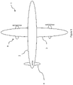
Figure 1 is a plan view of a first aircraft comprising a parallel hybrid propulsion system; -
Figure 2 is a schematic diagram of a parallel hybrid propulsion system for the aircraft offigure 1 ; -
Figure 3 is a schematic cross-sectional view of an electric machine suitable for the propulsion system offigure 2 ; -
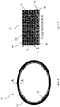
Figure 4 is a cross-sectional view of a rotor sleeve of the electric machine offigure 3 ; -
Figure 5 is a cross sectional along the line A-A offigure 4 ; -
Figure 6 is a diagram illustrating the ply directions of the rotor sleeve offigure 4 ; -
Figure 7 is a flow diagram illustrating a method of manufacturing the electric machine rotor offigure 3 ; and -
Figure 8 is a cross-sectional side view of an assembly apparatus for carrying out the method offigure 7 . - With reference to
Figure 1 , an aircraft 1 is shown. The aircraft is of conventional configuration, having afuselage 2,wings 3,tail 4 and a pair ofpropulsion systems 5. One of thepropulsion systems 5 is shown in figure detail infigure 2 . -
Figure 2 shows thepropulsion system 5 schematically. Thepropulsion system 5 includes an internal combustion engine in the form of agas turbine engine 10. Thegas turbine engine 10 comprises, in axial flow series, a propulsor in the form of a fan /propeller 12, acompressor 14,combustion equipment 16 and high and low-pressure turbines - The
gas turbine engine 10 works in the conventional manner so that air is accelerated by thefan 12 to produce two air flows: a first core air flow into thecompressor 14 and a second air flow which bypasses thecompressor 14 to provide propulsive thrust. The core air flows through thecompressor 14 where it is compressed, before delivering that air to thecombustion equipment 16, where it is mixed with fuel and the mixture combusted. The resultant hot combustion products then expand through, and thereby drive theturbines pressure turbines compressor 14 andfan 12, each by suitable interconnectingshaft - Other gas turbine engines to which the present disclosure may be applied may have alternative configurations. By way of example such engines may have an alternative number of interconnecting shafts (e.g. three) and/or an alternative number of compressors and/or turbines. Further, the engine may comprise a gearbox provided in the drive train from a turbine to a compressor and/or fan.
- The
propulsion system 5 further comprises one or more electrical machines. In particular, thesystem 5 comprises anelectric motor 28. Themotor 28 is of a conventional type, such as a permanent magnet electric machine, and is configured to drive a propulsor such as thefan 12. In the present embodiment, themotor 28 is coupled to thefan 12 via the low-pressure shaft 24. In this embodiment, theelectric motor 28 is of a "core shaft mounted" type, in which arotor 29 of themotor 28 is mounted directly to a surface of the low-pressure shaft 24, and is surrounded by astator 50, provided radially outwardly of therotor 29. The stator comprises electrical windings (not shown), which can be energised to produce a rotating magnetic field. This rotating magnetic field interacts with a magnetic field of therotor 29, to cause rotation when acting as a motor. Consequently, thefan 12 may be powered by either or both of thegas turbine engine 10 via the low-pressure turbine 20, and themotor 28. - The
electric motor 28 is coupled to anenergy storage device 30 in the form of one or more of a chemical battery, fuel cell, and capacitor, which provides theelectric motor 28 with electrical power during operation. In some cases, multiple energy storage systems, which may be of different types (chemical battery, fuel cell etc) may be provided for eachpropulsion system 5. In other cases, a commonenergy storage device 30 may be provided for multiple propulsion systems. - The propulsion system optionally comprises one or more further electric machines such as a
generator 32, which is coupled to one or both of themotor 28 and theenergy storage device 30, such that additional electrical energy can be provided in operation. Thegenerator 32 is typically driven by the low-pressure shaft 24 of thegas turbine engine 10. Thegenerator 32 may be coupled to theshaft 24 via a gearbox and / or clutch to allow for selectively connecting and disconnecting thegenerator 32 from theshaft 24. In some cases, themotor 28 may act as a generator. - Details of the
electric motor 28 are shown infigure 3 . As will be appreciated, thegenerator 32 is broadly similar to themotor 28. - The
motor 28 comprises arotor 29 and astator 50. - The
rotor 29 comprises ashaft 40 which defines a rotational axis X. Theshaft 40 is typically constructed from a structural material such as steel, aluminium or titanium, and is configured to be rotated by themotor 28 in use, and is coupled to thepropulsor 12. - Radially outward of the shaft is a plurality of
steel laminations 42. The steel laminations are typically thin, to minimise eddy currents, to thereby reduce losses and heat generation. - Radially outward of the
laminations 42 is a plurality ofpermanent magnets 44. Thepermanent magnets 44 are provided on a circumferential outer surface of thelaminations 42, and so the rotor can be said to be of the "surface permanent magnet" type. Thepermanent magnets 44 are typically adhered to the steel laminations by an adhesive. - In order to maintain the rotor in position in use, in opposition to centrifugal loads on the rotor, the rotor further comprises a
rotor sleeve 46 which is provided radially outward of and at least partly surrounding thepermanent magnets 44. Therotor sleeve 46 is described in further detail below, and is shown in more detail infigures 4 and 5 . - Radially outward of the
sleeve 46 is anair gap 48, which allows for relative rotation between the rotor andstator 50. Thestator 50 is provided radially outward of the air-gap 48 and comprises a plurality of stator coils (not shown), which, when energised, drive the rotor by interaction between the magnetic fields of the stator coils and thepermanent magnets 44. - Referring now to
figure 4 , therotor sleeve 46 is shown in more detail. The sleeve comprises aninner layer 52 andouter layer 54 which comprise different materials. - The
inner layer 52 comprises a compositematerial comprising filaments 56 of a first material having a relatively low modulus of elasticity. That is to say, the first material is relatively elastic, and can deform to a relatively large degree when a tensile force is applied. The material of the first filaments must also be relatively flexible, to allow it to be wound into shape. Examples of suitable materials include glass fibres (e.g. E-glass or S-glass), aramid, Polybenzoxazole (PBO), nylon, or Dynema, or a mixture of one of more of these materials. In one example, in the case of glass fibres, the fibres have a stiffness modulus of approximately 90 Giga-Pascals GPa. - The
fibres 56 of theinner layer 52 are embedded within a matrix material such a resin such as phenolic, epoxy, cyanate ester resin orPEEK 58. Together, thefibres 56 andresin 58 form a composite material. The matrix material in which the fibres are situated have an elastic modulus of approximately 8 GPa. For a volume fraction of 50%, this gives an overall elastic modulus of the low elastic modulus filament layer of approximately 50 GPa. - Similarly, the
outer layer 54 comprises a compositematerial comprising filaments 60 in amatrix material 62. However, thefilaments 60 are of a second material having a relatively high modulus of elasticity, i.e. higher than the modulus of elasticity than the first material. In this embodiment, thefilaments 60 comprise carbon fibre, though other fibre materials may be suitable. Thematrix material 62 may be the same as thematrix material 58 of theinner layer 52, or may be a different material to ensure compatibility with the different fibres materials. In one example, the filaments comprise a stiffness modulus of approximately 320 (GPa). The carbon fibre filaments are embedded within a matrix, with a volume fraction of approximately 65%. The matrix typically has an elastic modulus of approximately 8 GPa. This gives an overall elastic modulus for the carbon fibre composite layer of approximately 213 GPa. Consequently, the filaments of the outer layer have a modulus of elasticity approximately 3 to 4 times higher than the filaments of the inner layer. In other embodiments, the filaments of the inner layer may a stiffness closer to that of the outer layer. The ratio of outer layer fibre stiffness to inner fibre layer stiffness may be in the range of 2:1 to 40:1. - Though the drawings are not shown to scale, particular dimensions are illustrated in
figures 4 and 5 . The thickness T1 of the inner layer in the radial direction is approximately 0.5mm, and more generally is between 0.1 and 1mm. On the other hand, the thickness T2 of the outer layer is generally between 3 and 15mm, depending on the required strength and stiffness of thesleeve 46. - Typically, in order to optimise the properties of the inner and
outer layers filaments first layer 52 are provided as a plurality of sublayers, with the plies of each sub-layer being angled relative to a neighbouring layer. This ensures interlocking of the sub-layers, and enhances the multi-directional strength of theinner layer 52. Thefilaments 56 of theinner layer 52 are arranged approximately ±45° relative to the rotational axis X of the rotor 29 (i.e.filaments 56 lie approximately +45° angles and -45° angles). In some cases, rather than distinct sublayers, the plies of thefirst layer 52 may be interwoven, with filaments provided at alternating ±45° angles. In some cases, the filaments may be provided at between ±30° and ±60°. Thefilaments 60 of theouter layer 54 are arranged 90° to the rotational axis X for reasons that will be explained below. - The
filaments outer layers sleeve 46 compared to prior art composite or metallic sleeves. - Several methods may be used for construction of the sleeve. One method is to apply the
filaments permanent magnets 44, while applying tension to the filaments. The filaments could be pre-impregnated with matrix material (e.g. resin), or applied as sheets. Once applied, the composite material is then cured. In either case, thefilaments 56 of thefirst layer 52 will be applied first until the required thickness is built up, followed by thesecond layer 54. - However, a problem with this process is that the matrix material typically requires a high temperature to cure. On the other hand, if the curing process must be undertaken at a temperature below the Curie temperature of the
permanent magnets 44, otherwise magnetisation of the magnets will be lost. Consequently, the sleeve must be built up slowly and cured in multiple stages, resulting in a time consuming and slow process. This method also tends to lead to reduced pre-stress, since the pre-stress decreases during the curing step. The pre-stress using this installation method has been found to be limited to around 500-800 MPa in practice. - A second method is illustrating in
figure 7 , which utilises an apparatus shown infigure 7 . In a first step, thefilaments - In a second step, the structure is cured on the mandrel. Since the mandrel does not need to maintain magnetisation, the curing process can take place at a higher temperature.
- In a third step, the sleeve is optionally cut into smaller rings, and forced over a conical assembly tool 64, shown in
figure 8 . The assembly tool 64 has an outside diameter which tapers outwardly from a smaller diameter to a larger diameter which matches or slightly exceeds the outer diameter of thepermanent magnets 46 of therotor 29. By forcing thesleeve 46 over the mandrel, a pre-tension is applied, which increases the radially inward force applied by thesleeve 46 to thepermanent magnets 44 when installed. - In a fourth step, the
sleeve 46 is forced onto thepermanent magnets 44, until thesleeve 46 is fully installed in the desired position. At this point, thesleeve 46 is fully installed on therotor 29, with an interference fit. - This installation method with high level of pre-stress has previously been tried by the inventors with conventional composite sleeves, but has been unsuccessful. In those cases, the composite sleeve was damaged by the installation process, leading to breakage of the fibres. By providing an
inner layer 52 having a lower modulus of elasticity, the high modulus fibres are protected from mechanical damage during the press-fitting process, and so the sleeve can be more readily stretched over the assembly tool, without damaging the fibres of thesecond layer 54. - The disclosed sleeve and assembly method has been found by the inventors to provide a rotor sleeve having increased strength and reduced thickness relative to prior arrangements, in view of the increased pre-tension that can be applied. In one example, the radial thickness of the sleeve was reduced from 10.2mm to 8.4 mm. It will be appreciated that, as well as resulting in a direct reduction in weight, the reduced thickness also reduces the effective size of the airgap between the
rotor 29 andstator 50. This in turn increases the transmission of torque between the rotor and stator, and so increases power density. In one electric machine to which the sleeve has been applied by the inventors, this has resulted in an overall weight reduction of 77kg for a 2.5 megawatt (MW) electric machine. - It will be understood that the invention is not limited to the embodiments above-described and various modifications and improvements can be made without departing from the concepts described herein. Except where mutually exclusive, any of the features may be employed separately or in combination with any other features and the disclosure extends to and includes all combinations and subcombinations of one or more features described herein.
- The electric machine may be used for other applications. For example, the electric machine may be utilised as a starter/generator for a gas turbine engine.
- Alternatively, the electric machine may be used as either a generator or a motor in any other suitable application, such as an electric airliner that does not include a gas turbine engine.
Claims (17)
- A rotor sleeve (46) for a rotor (29) of an electric machine (28), the rotor sleeve (46) comprising:an inner layer (52) of wound filaments (56) comprising a first material having a first modulus of elasticity; andan outer layer (54) of wound filaments (60) wound around the inner layer (52), the outer layer (54) comprising a second material having a second modulus of elasticity higher than the first modulus.
- A rotor sleeve according to claim 1, wherein the inner and / or outer layer of wound filaments comprise pre-stressed filaments (56, 60).
- A rotor sleeve according to claim 1 or claim 2, wherein the outer layer of wound filaments (60) is pre-stressed to a stress of greater than 1000MPa, and may be stressed to a stress of between 500 and 1500 MPA.
- A rotor sleeve according to any of the preceding claims, wherein the inner and / or outer layer of wound filaments (56, 60) are provided within a matrix material (58, 62) such as epoxy, cyanate ester or phenolic resin.
- A rotor sleeve according to any of the preceding claims, wherein the inner layer of wound filaments (56) comprises any of glass fibre, aramid, PBO, E-glass, S-glass, nylon, or Dynema, or a mixture of one of more of these materials.
- A rotor sleeve according to any of the preceding claims, wherein the inner layer (52) comprises alternating ply angles of approximately +45° and - 45° relative to a rotational axis of the electric machine rotor (29) when installed.
- A rotor sleeve according to any of the preceding claims, wherein the inner layer (52) has a radial thickness of between 0.1 and 1 mm, and may have a radial thickness of approximately 0.5mm.
- A rotor sleeve according to any of the preceding claims, wherein the outer layer (54) comprises carbon or ceramic fibre.
- A rotor sleeve according to any of the preceding claims, wherein the outer layer (54) comprises ply angles of approximately 90° relative to a rotational axis of the electric machine rotor when installed.
- A method of manufacturing a sleeved rotor (29) of an electric machine (28), the method comprising:providing a rotor (29);providing a sleeve (46) comprising a first layer of wound filaments (56) comprising a first material having a first modulus of elasticity, and a second layer of wound filaments (60) wound around an outer diameter of the first layer and comprising a second material having a second modulus of elasticity higher than the first modulus; andsliding the sleeve (46) over an outer diameter of the rotor (29).
- A method according to claim 10, wherein the rotor (29) comprises one or more permanent magnets (44), and the sleeve (29) may be slide over the outer diameter over the one or more permanent magnets (44).
- A method according to claim 10 or claim 11, wherein the method comprises, in a first step, winding the inner and outer layers (52, 54) of filaments around a mandrel, followed by curing of the filaments (56, 60) to form a composite ring.
- A method according to any of claims 10 to 12, wherein the method comprises, in a second step subsequent to the first step, urging the cured ring over a conical stressing device to increase an inner diameter of the ring and produce a pre-stress on the ring, and sliding the sleeve over the outer diameter of the rotor.
- An electric machine comprising a rotor fitted with a sleeve according to any of claims 1 to 9.
- An electric machine according to claim 14, wherein the electric machine is configured to operate as one or both of a generator and a motor.
- An electric machine according to claim 14 or claim 15, wherein the electric machine comprises a permanent magnet electric machine comprising one or more surface permanent magnets provided at an outer diameter of the rotor.
- An aircraft propulsion system comprising an electric machine according to any of claims 14 to 16.
Applications Claiming Priority (1)
| Application Number | Priority Date | Filing Date | Title |
|---|---|---|---|
| GBGB2102581.2A GB202102581D0 (en) | 2021-02-24 | 2021-02-24 | Electric machine rotor sleeve |
Publications (2)
| Publication Number | Publication Date |
|---|---|
| EP4050768A1 true EP4050768A1 (en) | 2022-08-31 |
| EP4050768B1 EP4050768B1 (en) | 2024-08-21 |
Family
ID=75339117
Family Applications (1)
| Application Number | Title | Priority Date | Filing Date |
|---|---|---|---|
| EP22157653.1A Active EP4050768B1 (en) | 2021-02-24 | 2022-02-21 | Electric machine rotor sleeve |
Country Status (4)
| Country | Link |
|---|---|
| US (1) | US11863026B2 (en) |
| EP (1) | EP4050768B1 (en) |
| CN (1) | CN114977575A (en) |
| GB (1) | GB202102581D0 (en) |
Cited By (1)
| Publication number | Priority date | Publication date | Assignee | Title |
|---|---|---|---|---|
| EP4531245A1 (en) | 2023-09-27 | 2025-04-02 | Rolls-Royce plc | Rotor with protecting sleeve |
Families Citing this family (3)
| Publication number | Priority date | Publication date | Assignee | Title |
|---|---|---|---|---|
| US11787551B1 (en) | 2022-10-06 | 2023-10-17 | Archer Aviation, Inc. | Vertical takeoff and landing aircraft electric engine configuration |
| WO2024227808A1 (en) * | 2023-05-01 | 2024-11-07 | Novadrives Ip 1 Gmbh | Spoke magnet motor with pretensioned wrapping |
| US12500461B2 (en) | 2023-05-10 | 2025-12-16 | Rolls-Royce Corporation | Rotor with magnet retention band for use with electric machines |
Citations (3)
| Publication number | Priority date | Publication date | Assignee | Title |
|---|---|---|---|---|
| GB2250642A (en) * | 1990-10-25 | 1992-06-10 | Sundstrand Corp | Preventing leakage through dynamoelectric machine rotor anti-burst sleeve |
| US5485045A (en) * | 1991-12-20 | 1996-01-16 | Anton Piller Gmbh & Co. Kg | Rotor for permanent magnet-excited, high-speed electric machines and electric machine equipped with this rotor |
| US20150188369A1 (en) * | 2013-12-27 | 2015-07-02 | Fanuc Corporation | Rotor of electric motor with magnet holding structure and electric motor including the rotor |
Family Cites Families (13)
| Publication number | Priority date | Publication date | Assignee | Title |
|---|---|---|---|---|
| JP3509304B2 (en) | 1995-06-28 | 2004-03-22 | 株式会社明電舎 | Rotor permanent magnet |
| DE10224776A1 (en) | 2002-06-04 | 2004-03-11 | Magnet-Motor Gesellschaft Für Magnetmotorische Technik Mbh | Electrical machine |
| JP2012257413A (en) | 2011-06-10 | 2012-12-27 | Seiko Epson Corp | Electromechanical device, robot, movable body, and manufacturing method of electromechanical device |
| EP2842219B1 (en) | 2012-04-27 | 2017-08-23 | Atlas Copco Airpower N.V. | Method of composing a sleeve assembly for containment purposes in high centrifugal applications |
| EP2944565B1 (en) | 2014-05-13 | 2017-09-27 | Entrotech, Inc. | Erosion protective sleeve |
| CN204906030U (en) | 2014-12-01 | 2015-12-23 | 沈阳工业大学 | High -speed permanent -magnet machine rotor of compound protection of multilayer |
| JP2017163752A (en) | 2016-03-10 | 2017-09-14 | 株式会社明電舎 | Rotor of permanent magnet dynamo-electric machine |
| JP6464117B2 (en) * | 2016-06-24 | 2019-02-06 | ファナック株式会社 | Rotor member, rotor, and electric motor |
| JP6880668B2 (en) | 2016-11-16 | 2021-06-02 | トヨタ紡織株式会社 | Rotating machine rotor |
| US10763715B2 (en) * | 2017-12-27 | 2020-09-01 | Rolls Royce North American Technologies, Inc. | Nano-crystalline coating for magnet retention in a rotor assembly |
| GB2582345B (en) * | 2019-03-20 | 2023-06-28 | Safran Electrical & Power | Improved method for manufacturing a rotor |
| GB202102583D0 (en) | 2021-02-24 | 2021-04-07 | Rolls Royce Electrical Norway As | Electric machine rotor sleeve |
| GB202102582D0 (en) | 2021-02-24 | 2021-04-07 | Rolls Royce Electrical Norway As | Electric machine rotor sleeve |
-
2021
- 2021-02-24 GB GBGB2102581.2A patent/GB202102581D0/en not_active Ceased
-
2022
- 2022-02-14 US US17/670,857 patent/US11863026B2/en active Active
- 2022-02-21 EP EP22157653.1A patent/EP4050768B1/en active Active
- 2022-02-24 CN CN202210176832.3A patent/CN114977575A/en active Pending
Patent Citations (3)
| Publication number | Priority date | Publication date | Assignee | Title |
|---|---|---|---|---|
| GB2250642A (en) * | 1990-10-25 | 1992-06-10 | Sundstrand Corp | Preventing leakage through dynamoelectric machine rotor anti-burst sleeve |
| US5485045A (en) * | 1991-12-20 | 1996-01-16 | Anton Piller Gmbh & Co. Kg | Rotor for permanent magnet-excited, high-speed electric machines and electric machine equipped with this rotor |
| US20150188369A1 (en) * | 2013-12-27 | 2015-07-02 | Fanuc Corporation | Rotor of electric motor with magnet holding structure and electric motor including the rotor |
Cited By (1)
| Publication number | Priority date | Publication date | Assignee | Title |
|---|---|---|---|---|
| EP4531245A1 (en) | 2023-09-27 | 2025-04-02 | Rolls-Royce plc | Rotor with protecting sleeve |
Also Published As
| Publication number | Publication date |
|---|---|
| EP4050768B1 (en) | 2024-08-21 |
| CN114977575A (en) | 2022-08-30 |
| US20220271588A1 (en) | 2022-08-25 |
| GB202102581D0 (en) | 2021-04-07 |
| US11863026B2 (en) | 2024-01-02 |
Similar Documents
| Publication | Publication Date | Title |
|---|---|---|
| EP4050770B1 (en) | Electric machine rotor sleeve | |
| EP4050768B1 (en) | Electric machine rotor sleeve | |
| US12126238B2 (en) | Electric machine rotor sleeve | |
| US12355302B2 (en) | Method for manufacturing a rotor | |
| US5285699A (en) | Reinforced composite flywheels and shafts | |
| EP3633160B1 (en) | Gas turbine engine with integrated energy storage device | |
| CN108625986B (en) | Electric machine with separable magnet carrier | |
| US20100327588A1 (en) | Gas turbine with magnetic shaft forming part of a generator/motor assembly | |
| US20170310175A1 (en) | Holding member, rotor of a rotating electrical machine comprising the same, and a rotating electrical machine comprising the rotor | |
| US4996016A (en) | Methods for making reinforced composite flywheels and shafts | |
| EP1584797A2 (en) | A containment apparatus for a gas turbine engine | |
| EP1050947B1 (en) | Rotor for an electrical machine, and an electrical machine including such a rotor | |
| Binder et al. | Fixation of buried and surface mounted magnets in high-speed permanent magnet synchronous motors | |
| Ha et al. | Design and manufacture of a composite flywheel press-fit multi-rim rotor | |
| WO2012043940A1 (en) | Hub for flywheel and flywheel for energy storage having same | |
| Curtiss et al. | Advanced composite flywheel structural design for a pulsed disk alternator | |
| US11374447B2 (en) | Hybrid rotor for an axial flux electrical machine | |
| US20220302779A1 (en) | Rotor assembly | |
| JPWO2018167869A1 (en) | Rotating body, electric compressor and turbine generator | |
| WO2012043939A1 (en) | Preparation method of flywheel hub | |
| Herbst et al. | Status of the 9 MJ range gun system | |
| EP4531245A1 (en) | Rotor with protecting sleeve | |
| US20240120789A1 (en) | Composite structures for electric motors | |
| JP2000081091A (en) | Flywheel | |
| EP4181353A1 (en) | Composite magnet carrier |
Legal Events
| Date | Code | Title | Description |
|---|---|---|---|
| PUAI | Public reference made under article 153(3) epc to a published international application that has entered the european phase |
Free format text: ORIGINAL CODE: 0009012 |
|
| STAA | Information on the status of an ep patent application or granted ep patent |
Free format text: STATUS: THE APPLICATION HAS BEEN PUBLISHED |
|
| AK | Designated contracting states |
Kind code of ref document: A1 Designated state(s): AL AT BE BG CH CY CZ DE DK EE ES FI FR GB GR HR HU IE IS IT LI LT LU LV MC MK MT NL NO PL PT RO RS SE SI SK SM TR |
|
| STAA | Information on the status of an ep patent application or granted ep patent |
Free format text: STATUS: REQUEST FOR EXAMINATION WAS MADE |
|
| 17P | Request for examination filed |
Effective date: 20230222 |
|
| RBV | Designated contracting states (corrected) |
Designated state(s): AL AT BE BG CH CY CZ DE DK EE ES FI FR GB GR HR HU IE IS IT LI LT LU LV MC MK MT NL NO PL PT RO RS SE SI SK SM TR |
|
| GRAP | Despatch of communication of intention to grant a patent |
Free format text: ORIGINAL CODE: EPIDOSNIGR1 |
|
| STAA | Information on the status of an ep patent application or granted ep patent |
Free format text: STATUS: GRANT OF PATENT IS INTENDED |
|
| GRAS | Grant fee paid |
Free format text: ORIGINAL CODE: EPIDOSNIGR3 |
|
| INTG | Intention to grant announced |
Effective date: 20240621 |
|
| GRAA | (expected) grant |
Free format text: ORIGINAL CODE: 0009210 |
|
| STAA | Information on the status of an ep patent application or granted ep patent |
Free format text: STATUS: THE PATENT HAS BEEN GRANTED |
|
| AK | Designated contracting states |
Kind code of ref document: B1 Designated state(s): AL AT BE BG CH CY CZ DE DK EE ES FI FR GB GR HR HU IE IS IT LI LT LU LV MC MK MT NL NO PL PT RO RS SE SI SK SM TR |
|
| REG | Reference to a national code |
Ref country code: GB Ref legal event code: FG4D |
|
| REG | Reference to a national code |
Ref country code: CH Ref legal event code: EP |
|
| REG | Reference to a national code |
Ref country code: IE Ref legal event code: FG4D |
|
| REG | Reference to a national code |
Ref country code: DE Ref legal event code: R096 Ref document number: 602022005389 Country of ref document: DE |
|
| P01 | Opt-out of the competence of the unified patent court (upc) registered |
Free format text: CASE NUMBER: APP_50249/2024 Effective date: 20240904 |
|
| REG | Reference to a national code |
Ref country code: LT Ref legal event code: MG9D |
|
| REG | Reference to a national code |
Ref country code: NL Ref legal event code: MP Effective date: 20240821 |
|
| PG25 | Lapsed in a contracting state [announced via postgrant information from national office to epo] |
Ref country code: NO Free format text: LAPSE BECAUSE OF FAILURE TO SUBMIT A TRANSLATION OF THE DESCRIPTION OR TO PAY THE FEE WITHIN THE PRESCRIBED TIME-LIMIT Effective date: 20241121 |
|
| REG | Reference to a national code |
Ref country code: AT Ref legal event code: MK05 Ref document number: 1716496 Country of ref document: AT Kind code of ref document: T Effective date: 20240821 |
|
| PG25 | Lapsed in a contracting state [announced via postgrant information from national office to epo] |
Ref country code: FI Free format text: LAPSE BECAUSE OF FAILURE TO SUBMIT A TRANSLATION OF THE DESCRIPTION OR TO PAY THE FEE WITHIN THE PRESCRIBED TIME-LIMIT Effective date: 20240821 Ref country code: NL Free format text: LAPSE BECAUSE OF FAILURE TO SUBMIT A TRANSLATION OF THE DESCRIPTION OR TO PAY THE FEE WITHIN THE PRESCRIBED TIME-LIMIT Effective date: 20240821 Ref country code: PT Free format text: LAPSE BECAUSE OF FAILURE TO SUBMIT A TRANSLATION OF THE DESCRIPTION OR TO PAY THE FEE WITHIN THE PRESCRIBED TIME-LIMIT Effective date: 20241223 Ref country code: PL Free format text: LAPSE BECAUSE OF FAILURE TO SUBMIT A TRANSLATION OF THE DESCRIPTION OR TO PAY THE FEE WITHIN THE PRESCRIBED TIME-LIMIT Effective date: 20240821 Ref country code: GR Free format text: LAPSE BECAUSE OF FAILURE TO SUBMIT A TRANSLATION OF THE DESCRIPTION OR TO PAY THE FEE WITHIN THE PRESCRIBED TIME-LIMIT Effective date: 20241122 |
|
| PG25 | Lapsed in a contracting state [announced via postgrant information from national office to epo] |
Ref country code: BG Free format text: LAPSE BECAUSE OF FAILURE TO SUBMIT A TRANSLATION OF THE DESCRIPTION OR TO PAY THE FEE WITHIN THE PRESCRIBED TIME-LIMIT Effective date: 20240821 |
|
| PG25 | Lapsed in a contracting state [announced via postgrant information from national office to epo] |
Ref country code: LV Free format text: LAPSE BECAUSE OF FAILURE TO SUBMIT A TRANSLATION OF THE DESCRIPTION OR TO PAY THE FEE WITHIN THE PRESCRIBED TIME-LIMIT Effective date: 20240821 |
|
| PG25 | Lapsed in a contracting state [announced via postgrant information from national office to epo] |
Ref country code: AT Free format text: LAPSE BECAUSE OF FAILURE TO SUBMIT A TRANSLATION OF THE DESCRIPTION OR TO PAY THE FEE WITHIN THE PRESCRIBED TIME-LIMIT Effective date: 20240821 Ref country code: IS Free format text: LAPSE BECAUSE OF FAILURE TO SUBMIT A TRANSLATION OF THE DESCRIPTION OR TO PAY THE FEE WITHIN THE PRESCRIBED TIME-LIMIT Effective date: 20241221 |
|
| PG25 | Lapsed in a contracting state [announced via postgrant information from national office to epo] |
Ref country code: HR Free format text: LAPSE BECAUSE OF FAILURE TO SUBMIT A TRANSLATION OF THE DESCRIPTION OR TO PAY THE FEE WITHIN THE PRESCRIBED TIME-LIMIT Effective date: 20240821 |
|
| PG25 | Lapsed in a contracting state [announced via postgrant information from national office to epo] |
Ref country code: ES Free format text: LAPSE BECAUSE OF FAILURE TO SUBMIT A TRANSLATION OF THE DESCRIPTION OR TO PAY THE FEE WITHIN THE PRESCRIBED TIME-LIMIT Effective date: 20240821 Ref country code: RS Free format text: LAPSE BECAUSE OF FAILURE TO SUBMIT A TRANSLATION OF THE DESCRIPTION OR TO PAY THE FEE WITHIN THE PRESCRIBED TIME-LIMIT Effective date: 20241121 |
|
| PG25 | Lapsed in a contracting state [announced via postgrant information from national office to epo] |
Ref country code: RS Free format text: LAPSE BECAUSE OF FAILURE TO SUBMIT A TRANSLATION OF THE DESCRIPTION OR TO PAY THE FEE WITHIN THE PRESCRIBED TIME-LIMIT Effective date: 20241121 Ref country code: PT Free format text: LAPSE BECAUSE OF FAILURE TO SUBMIT A TRANSLATION OF THE DESCRIPTION OR TO PAY THE FEE WITHIN THE PRESCRIBED TIME-LIMIT Effective date: 20241223 Ref country code: PL Free format text: LAPSE BECAUSE OF FAILURE TO SUBMIT A TRANSLATION OF THE DESCRIPTION OR TO PAY THE FEE WITHIN THE PRESCRIBED TIME-LIMIT Effective date: 20240821 Ref country code: NO Free format text: LAPSE BECAUSE OF FAILURE TO SUBMIT A TRANSLATION OF THE DESCRIPTION OR TO PAY THE FEE WITHIN THE PRESCRIBED TIME-LIMIT Effective date: 20241121 Ref country code: NL Free format text: LAPSE BECAUSE OF FAILURE TO SUBMIT A TRANSLATION OF THE DESCRIPTION OR TO PAY THE FEE WITHIN THE PRESCRIBED TIME-LIMIT Effective date: 20240821 Ref country code: LV Free format text: LAPSE BECAUSE OF FAILURE TO SUBMIT A TRANSLATION OF THE DESCRIPTION OR TO PAY THE FEE WITHIN THE PRESCRIBED TIME-LIMIT Effective date: 20240821 Ref country code: IS Free format text: LAPSE BECAUSE OF FAILURE TO SUBMIT A TRANSLATION OF THE DESCRIPTION OR TO PAY THE FEE WITHIN THE PRESCRIBED TIME-LIMIT Effective date: 20241221 Ref country code: HR Free format text: LAPSE BECAUSE OF FAILURE TO SUBMIT A TRANSLATION OF THE DESCRIPTION OR TO PAY THE FEE WITHIN THE PRESCRIBED TIME-LIMIT Effective date: 20240821 Ref country code: GR Free format text: LAPSE BECAUSE OF FAILURE TO SUBMIT A TRANSLATION OF THE DESCRIPTION OR TO PAY THE FEE WITHIN THE PRESCRIBED TIME-LIMIT Effective date: 20241122 Ref country code: FI Free format text: LAPSE BECAUSE OF FAILURE TO SUBMIT A TRANSLATION OF THE DESCRIPTION OR TO PAY THE FEE WITHIN THE PRESCRIBED TIME-LIMIT Effective date: 20240821 Ref country code: ES Free format text: LAPSE BECAUSE OF FAILURE TO SUBMIT A TRANSLATION OF THE DESCRIPTION OR TO PAY THE FEE WITHIN THE PRESCRIBED TIME-LIMIT Effective date: 20240821 Ref country code: BG Free format text: LAPSE BECAUSE OF FAILURE TO SUBMIT A TRANSLATION OF THE DESCRIPTION OR TO PAY THE FEE WITHIN THE PRESCRIBED TIME-LIMIT Effective date: 20240821 Ref country code: AT Free format text: LAPSE BECAUSE OF FAILURE TO SUBMIT A TRANSLATION OF THE DESCRIPTION OR TO PAY THE FEE WITHIN THE PRESCRIBED TIME-LIMIT Effective date: 20240821 |
|
| PG25 | Lapsed in a contracting state [announced via postgrant information from national office to epo] |
Ref country code: DK Free format text: LAPSE BECAUSE OF FAILURE TO SUBMIT A TRANSLATION OF THE DESCRIPTION OR TO PAY THE FEE WITHIN THE PRESCRIBED TIME-LIMIT Effective date: 20240821 Ref country code: RO Free format text: LAPSE BECAUSE OF FAILURE TO SUBMIT A TRANSLATION OF THE DESCRIPTION OR TO PAY THE FEE WITHIN THE PRESCRIBED TIME-LIMIT Effective date: 20240821 Ref country code: SM Free format text: LAPSE BECAUSE OF FAILURE TO SUBMIT A TRANSLATION OF THE DESCRIPTION OR TO PAY THE FEE WITHIN THE PRESCRIBED TIME-LIMIT Effective date: 20240821 |
|
| PG25 | Lapsed in a contracting state [announced via postgrant information from national office to epo] |
Ref country code: EE Free format text: LAPSE BECAUSE OF FAILURE TO SUBMIT A TRANSLATION OF THE DESCRIPTION OR TO PAY THE FEE WITHIN THE PRESCRIBED TIME-LIMIT Effective date: 20240821 |
|
| PG25 | Lapsed in a contracting state [announced via postgrant information from national office to epo] |
Ref country code: CZ Free format text: LAPSE BECAUSE OF FAILURE TO SUBMIT A TRANSLATION OF THE DESCRIPTION OR TO PAY THE FEE WITHIN THE PRESCRIBED TIME-LIMIT Effective date: 20240821 |
|
| PG25 | Lapsed in a contracting state [announced via postgrant information from national office to epo] |
Ref country code: SK Free format text: LAPSE BECAUSE OF FAILURE TO SUBMIT A TRANSLATION OF THE DESCRIPTION OR TO PAY THE FEE WITHIN THE PRESCRIBED TIME-LIMIT Effective date: 20240821 Ref country code: IT Free format text: LAPSE BECAUSE OF FAILURE TO SUBMIT A TRANSLATION OF THE DESCRIPTION OR TO PAY THE FEE WITHIN THE PRESCRIBED TIME-LIMIT Effective date: 20240821 |
|
| REG | Reference to a national code |
Ref country code: DE Ref legal event code: R097 Ref document number: 602022005389 Country of ref document: DE |
|
| PLBE | No opposition filed within time limit |
Free format text: ORIGINAL CODE: 0009261 |
|
| STAA | Information on the status of an ep patent application or granted ep patent |
Free format text: STATUS: NO OPPOSITION FILED WITHIN TIME LIMIT |
|
| 26N | No opposition filed |
Effective date: 20250522 |
|
| PG25 | Lapsed in a contracting state [announced via postgrant information from national office to epo] |
Ref country code: SE Free format text: LAPSE BECAUSE OF FAILURE TO SUBMIT A TRANSLATION OF THE DESCRIPTION OR TO PAY THE FEE WITHIN THE PRESCRIBED TIME-LIMIT Effective date: 20240821 |
|
| PG25 | Lapsed in a contracting state [announced via postgrant information from national office to epo] |
Ref country code: MC Free format text: LAPSE BECAUSE OF FAILURE TO SUBMIT A TRANSLATION OF THE DESCRIPTION OR TO PAY THE FEE WITHIN THE PRESCRIBED TIME-LIMIT Effective date: 20240821 |
|
| REG | Reference to a national code |
Ref country code: CH Ref legal event code: PL |
|
| PG25 | Lapsed in a contracting state [announced via postgrant information from national office to epo] |
Ref country code: LU Free format text: LAPSE BECAUSE OF NON-PAYMENT OF DUE FEES Effective date: 20250221 |
|
| PG25 | Lapsed in a contracting state [announced via postgrant information from national office to epo] |
Ref country code: CH Free format text: LAPSE BECAUSE OF NON-PAYMENT OF DUE FEES Effective date: 20250228 |
|
| REG | Reference to a national code |
Ref country code: BE Ref legal event code: MM Effective date: 20250228 |
|
| PG25 | Lapsed in a contracting state [announced via postgrant information from national office to epo] |
Ref country code: BE Free format text: LAPSE BECAUSE OF NON-PAYMENT OF DUE FEES Effective date: 20250228 |
|
| PG25 | Lapsed in a contracting state [announced via postgrant information from national office to epo] |
Ref country code: IE Free format text: LAPSE BECAUSE OF NON-PAYMENT OF DUE FEES Effective date: 20250221 |
|
| PGFP | Annual fee paid to national office [announced via postgrant information from national office to epo] |
Ref country code: GB Payment date: 20260223 Year of fee payment: 5 |
|
| PGFP | Annual fee paid to national office [announced via postgrant information from national office to epo] |
Ref country code: DE Payment date: 20260220 Year of fee payment: 5 |
|
| PGFP | Annual fee paid to national office [announced via postgrant information from national office to epo] |
Ref country code: FR Payment date: 20260224 Year of fee payment: 5 |