EP4050767A1 - Rotor and ipm motor including the same - Google Patents
Rotor and ipm motor including the same Download PDFInfo
- Publication number
- EP4050767A1 EP4050767A1 EP22158613.4A EP22158613A EP4050767A1 EP 4050767 A1 EP4050767 A1 EP 4050767A1 EP 22158613 A EP22158613 A EP 22158613A EP 4050767 A1 EP4050767 A1 EP 4050767A1
- Authority
- EP
- European Patent Office
- Prior art keywords
- rotor
- magnet
- insertion hole
- positioning member
- core
- Prior art date
- Legal status (The legal status is an assumption and is not a legal conclusion. Google has not performed a legal analysis and makes no representation as to the accuracy of the status listed.)
- Granted
Links
Images


Classifications
-
- H—ELECTRICITY
- H02—GENERATION; CONVERSION OR DISTRIBUTION OF ELECTRIC POWER
- H02K—DYNAMO-ELECTRIC MACHINES
- H02K1/00—Details of the magnetic circuit
- H02K1/06—Details of the magnetic circuit characterised by the shape, form or construction
- H02K1/22—Rotating parts of the magnetic circuit
- H02K1/27—Rotor cores with permanent magnets
- H02K1/2706—Inner rotors
- H02K1/272—Inner rotors the magnetisation axis of the magnets being perpendicular to the rotor axis
- H02K1/274—Inner rotors the magnetisation axis of the magnets being perpendicular to the rotor axis the rotor consisting of two or more circumferentially positioned magnets
- H02K1/2753—Inner rotors the magnetisation axis of the magnets being perpendicular to the rotor axis the rotor consisting of two or more circumferentially positioned magnets the rotor consisting of magnets or groups of magnets arranged with alternating polarity
- H02K1/276—Magnets embedded in the magnetic core, e.g. interior permanent magnets [IPM]
-
- H—ELECTRICITY
- H02—GENERATION; CONVERSION OR DISTRIBUTION OF ELECTRIC POWER
- H02K—DYNAMO-ELECTRIC MACHINES
- H02K1/00—Details of the magnetic circuit
- H02K1/06—Details of the magnetic circuit characterised by the shape, form or construction
- H02K1/22—Rotating parts of the magnetic circuit
-
- H—ELECTRICITY
- H02—GENERATION; CONVERSION OR DISTRIBUTION OF ELECTRIC POWER
- H02K—DYNAMO-ELECTRIC MACHINES
- H02K1/00—Details of the magnetic circuit
- H02K1/06—Details of the magnetic circuit characterised by the shape, form or construction
- H02K1/22—Rotating parts of the magnetic circuit
- H02K1/28—Means for mounting or fastening rotating magnetic parts on to, or to, the rotor structures
-
- H—ELECTRICITY
- H02—GENERATION; CONVERSION OR DISTRIBUTION OF ELECTRIC POWER
- H02K—DYNAMO-ELECTRIC MACHINES
- H02K15/00—Processes or apparatus specially adapted for manufacturing, assembling, maintaining or repairing of dynamo-electric machines
- H02K15/02—Processes or apparatus specially adapted for manufacturing, assembling, maintaining or repairing of dynamo-electric machines of stator or rotor bodies
- H02K15/021—Magnetic cores
- H02K15/026—Wound cores
-
- Y—GENERAL TAGGING OF NEW TECHNOLOGICAL DEVELOPMENTS; GENERAL TAGGING OF CROSS-SECTIONAL TECHNOLOGIES SPANNING OVER SEVERAL SECTIONS OF THE IPC; TECHNICAL SUBJECTS COVERED BY FORMER USPC CROSS-REFERENCE ART COLLECTIONS [XRACs] AND DIGESTS
- Y02—TECHNOLOGIES OR APPLICATIONS FOR MITIGATION OR ADAPTATION AGAINST CLIMATE CHANGE
- Y02T—CLIMATE CHANGE MITIGATION TECHNOLOGIES RELATED TO TRANSPORTATION
- Y02T10/00—Road transport of goods or passengers
- Y02T10/60—Other road transportation technologies with climate change mitigation effect
- Y02T10/64—Electric machine technologies in electromobility
Definitions
- Patent Literature 1 discloses a rotor in which an adhesive sheet is interposed between a permanent magnet and a rotor core in a slit hole, and the adhesive sheet is expanded and cured to fix the permanent magnet in the slit hole.
- Patent Literature 1 JP 2006-311782 A
- An object of the present invention is to provide a rotor that allows a rotor magnet inserted in a magnet insertion hole of a rotor core to be easily and accurately positioned in the magnet insertion hole.
- the rotor 2 includes a rotor core 21, a rotor magnet 22, and a positioning member 23.
- the rotor 2 is located radially inward of the stator 3 and is rotatable with respect to the stator 3.
- the rotor core 21 has a columnar shape extending along the central axis P.
- the shaft 20 extending along the central axis P is fixed to and penetrates the rotor core 21 in the axial direction. As a result, the rotor core 21 rotates with the shaft 20.
- the rotor core 21 has the pair of protrusions 27 protruding into the magnet insertion hole 24 on the insertion hole inner surface 24a.
- the rotor core may have a pair of protrusions at other positions on the inner surface of the magnet insertion hole.
Landscapes
- Engineering & Computer Science (AREA)
- Power Engineering (AREA)
- Manufacturing & Machinery (AREA)
- Permanent Field Magnets Of Synchronous Machinery (AREA)
- Iron Core Of Rotating Electric Machines (AREA)
Abstract
Description
- The present invention relates to a rotor and an IPM motor including the rotor.
- A rotor for an IPM motor in which a rotor magnet is inserted in a magnet insertion hole extending in the axial direction of a rotor core is known. Additionally, a configuration for positioning the rotor magnet in the magnet insertion hole in the rotor is disclosed. For example, Patent Literature 1 discloses a rotor in which an adhesive sheet is interposed between a permanent magnet and a rotor core in a slit hole, and the adhesive sheet is expanded and cured to fix the permanent magnet in the slit hole.
- Patent Literature 1:
JP 2006-311782 A - In the rotor disclosed in Patent Literature 1, the adhesive sheet interposed between the permanent magnet and the rotor core has one adhesive layer that expands by heating and a base material layer that holds the adhesive layer. In the rotor of Patent Literature 1, the adhesive layer is adhered to the permanent magnet. In the rotor, the base material layer, which is not an expanding member, is in contact with an inner surface of the slit hole of the rotor core. Accordingly, in the rotor of Patent Literature 1, the degree of adhesion of the adhesive sheet to the inner surface of the slit hole is not sufficient, and the positioning accuracy of the permanent magnet with respect to the rotor core may not be sufficient.
- Hence, in a rotor in which a rotor magnet is inserted in a magnet insertion hole of a rotor core, there is a need for a configuration that allows the rotor magnet to be easily and accurately positioned in the magnet insertion hole.
- An object of the present invention is to provide a rotor that allows a rotor magnet inserted in a magnet insertion hole of a rotor core to be easily and accurately positioned in the magnet insertion hole.
- A rotor according to an embodiment of the present invention is a rotor including a columnar rotor core that has a magnet insertion hole penetrating the rotor core in the axial direction, a rotor magnet inserted into the magnet insertion hole, and a positioning member that positions the rotor magnet in the magnet insertion hole. The positioning member includes a first foam layer containing an adhesive that adheres to the rotor magnet, a second foam layer in contact with the inner surface of the magnet insertion hole of the rotor core, and a base material layer located between the first foam layer and the second foam layer. The first foam layer, the second foam layer, and the base material layer are laminated and located between the rotor magnet and the inner surface of the magnet insertion hole.
- An IPM motor according to an embodiment of the present invention includes the rotor and a stator having a stator coil and a stator core.
- According to the rotor of the embodiment of the present invention, the rotor magnet can be easily and accurately positioned in the magnet insertion hole of the rotor core. Brief Description of Drawings
-
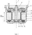
Fig. 1 is a cross-sectional view showing a schematic configuration of an IPM motor according to an embodiment. -
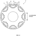
Fig. 2 is a plan view of a rotor. -
Fig. 3 is a partially enlarged view ofFig. 2 . -
Fig. 4 is a cross-sectional view taken along line IV-IV inFig. 3 . -
Fig. 5 is a diagram showing a schematic configuration of a positioning member before foaming. -
Fig. 6A is a diagram illustrating a method of manufacturing the rotor according to the embodiment. -
Fig. 6B is a diagram illustrating the method of manufacturing the rotor according to the embodiment. -
Fig. 6C is a diagram illustrating the method of manufacturing the rotor according to the embodiment. -
Fig. 7A is a diagram showing the position of a rotor magnet before heating. -
Fig. 7B is a diagram showing the position of the rotor magnet after heating. - Hereinafter, an exemplary embodiment of the present invention will be described in detail with reference to the drawings. Note that the same or corresponding parts in the drawings are denoted by the same reference numerals, and the description thereof will not be repeated. The dimensions of constituent members in each drawing do not faithfully represent the actual dimensions of the constituent members, the dimensional ratio of each constituent member, or the like.
- Note that in the following description of a motor 1, a direction parallel to a central axis P of a
rotor 2 is referred to as "axial direction", a direction perpendicular to the central axis P is referred to as "radial direction", and a direction along a circular arc centered on the central axis P is referred to as "circumferential direction". Note, however, that the definitions of directions are not intended to limit the direction of therotor 2 when in use. A "longitudinal direction" and "transverse direction" of arotor magnet 22 and amagnet insertion hole 24 refer to the longitudinal direction and the transverse direction of therotor magnet 22 and themagnet insertion hole 24 when therotor 2 is viewed in the axial direction. - In the following description, the expression "fix", "connect", "attach", or the like (hereinafter, fix or the like) is used not only when members are directly fixed or the like to each other, but also when members are fixed or the like to each other with another member interposed therebetween. That is, in the following description, the expression "fix or the like" includes the meaning of direct and indirect fixation or the like of members.
-
Fig. 1 shows a schematic configuration of a motor 1 which is an IPM motor having arotor 2 of an exemplary embodiment of the present invention. The motor 1 includes arotor 2, a stator 3, ahousing 4, and ashaft 20. Therotor 2 is a rotor for an IPM motor in which a magnet is embedded in the rotor. Therotor 2 rotates about a central axis P with respect to the stator 3. In the present embodiment, the motor 1 is a so-called inner rotor motor in which therotor 2 is located so as to be rotatable about the central axis P in the tubular stator 3. - The
rotor 2 includes arotor core 21, arotor magnet 22, and apositioning member 23. Therotor 2 is located radially inward of the stator 3 and is rotatable with respect to the stator 3. - The
rotor core 21 has a columnar shape extending along the central axis P. Theshaft 20 extending along the central axis P is fixed to and penetrates therotor core 21 in the axial direction. As a result, therotor core 21 rotates with theshaft 20. - The
rotor core 21 is formed by laminating multiple disk-shapedrotor core plates 25 in the thickness direction. Themultiple core plates 25 are made of electromagnetic steel plates. - The
rotor core 21 has amagnet insertion hole 24 that axially penetratesmultiple core plates 25 laminated in the thickness direction. Themagnet insertion hole 24 has a rectangular shape, for example, when therotor core 21 is viewed in the axial direction. Each of themultiple core plates 25 has a throughhole 26 forming themagnet insertion hole 24. - The
rotor magnet 22 has a rectangular parallelepiped shape extending in the axial direction. That is, therotor magnet 22 has a rectangular shape when therotor core 21 is viewed in the axial direction. The axial length of therotor magnet 22 is equal to or slightly shorter than the axial length of therotor core 21. Therotor magnet 22 is positioned at a predetermined position by the positioningmember 23 while being housed in themagnet insertion hole 24. - In the following, for the sake of explanation, when the
rotor magnet 22 is viewed in the axial direction, a surface forming the long side of therotor magnet 22 is referred to as a long side lateral face of therotor magnet 22, and a surface forming the short side of therotor magnet 22 is referred to as a short side lateral face of therotor magnet 22. A detailed description of the positioningmember 23 will be given later. - The stator 3 is housed in the
housing 4. In the present embodiment, the stator 3 has a tubular shape. Therotor 2 is located radially inward of the stator 3. That is, the stator 3 is located so as to face therotor 2 in the radial direction. Therotor 2 is located radially inward of the stator 3 so as to be rotatable about the central axis P. - The stator 3 includes a
stator core 31 and astator coil 36. Thestator core 31 has a cylindrical shape extending in the axial direction. Thestator coil 36 is wound around thestator core 31. The stator 3 has a configuration similar to that of a general stator. Hence, a detailed description of the stator 3 will be omitted. - Next, the
rotor 2 will be described in detail with reference toFigs. 2 to 4 . -
Fig. 2 is a diagram of therotor 2 as viewed in the axial direction. As shown inFig. 2 , in the present embodiment, therotor core 21 has 24 magnet insertion holes 24. Arotor magnet 22 is housed in each of the 24 magnet insertion holes 24. Note that while there are 24 magnet insertion holes 24 in the present embodiment, the number of magnet insertion holes 24 does not necessarily have to be 24. - The longitudinal direction of 16 magnet insertion holes 24 out of the 24 magnet insertion holes 24 is inclined with respect to a radial line extending in the radial direction of the
rotor 2. The longitudinal direction of eight magnet insertion holes 24 out of the 24 magnet insertion holes 24 is orthogonal to the radial line. As described above, in the present embodiment, none of the longitudinal directions of the magnet insertion holes 24 coincide with the radial line. Hence, in all the magnet insertion holes 24, a pair of surfaces forming the long sides when viewed in the axial direction, among surfaces forming the inner surface of themagnet insertion hole 24 has one surface located more inward than the other surface in the radial direction of therotor core 21. In the following description, of the pair of surfaces, the surface located radially inward is referred to as an insertion holeinner surface 24a, and the surface located radially outward is referred to as an insertion holeouter surface 24b. Note that the positions and longitudinal directions of the magnet insertion holes 24 do not necessarily have to be the positions and longitudinal directions shown inFig. 2 . -
Fig. 3 is an enlarged view of a part surrounded by a broken line inFig. 2 . As shown inFig. 3 , in therotor magnet 22 inserted in themagnet insertion hole 24, one of the pair of long side lateral faces is located more inward than the other, in the radial direction of therotor core 21. In the following description, of the pair of long side lateral faces, the surface located radially inward is referred to as a magnetinner surface 51, and the surface located radially outward is referred to as a magnetouter surface 52. When therotor magnet 22 is inserted in themagnet insertion hole 24, the magnetouter surface 52 faces the insertion holeouter surface 24b of themagnet insertion hole 24. The positioningmember 23, which will be described later, is located between the magnetinner surface 51 and the insertion holeinner surface 24a of themagnet insertion hole 24. - The
rotor core 21 has, on the insertion holeinner surface 24a, a pair ofprotrusions 27 protruding into themagnet insertion hole 24. When therotor magnet 22 is housed in themagnet insertion hole 24, one of the pair ofprotrusions 27 faces one short side of therotor magnet 22, and the other of theprotrusions 27 faces the other short side of therotor magnet 22. That is, the pair ofprotrusions 27 restrict therotor magnet 22 from moving in the longitudinal direction in themagnet insertion hole 24. - The positioning
member 23 is formed of a member that foams by heating. The positioningmember 23 is located between the magnetinner surface 51 of therotor magnet 22 and the insertion holeinner surface 24a of themagnet insertion hole 24. When the positioningmember 23 is expanded by foaming, the positioningmember 23 fills a gap between therotor magnet 22 and the inner surface of themagnet insertion hole 24 in themagnet insertion hole 24. -
Fig. 4 is a cross-sectional view taken along line IV-IV inFig. 3 . As shown inFigs. 3 and 4 , the positioningmember 23 is configured by laminating sheet-like members. In the positioningmember 23, a magnet-side foam layer 55, abase material layer 57, and a rotor core-side foam layer 56 are laminated in this order from the side in contact with therotor magnet 22. The magnet-side foam layer 55 corresponds to a first foam layer. The rotor core-side foam layer 56 corresponds to a second foam layer. - The magnet-
side foam layer 55 contains a thermosetting resin and a foaming agent foamed by heating. As the foaming agent, microcapsules containing a low melting point organic solvent such as alcohol are often used. The thermosetting resin is preferably composed of a thermosetting adhesive. Examples of the thermosetting adhesive include a phenol-based adhesive, a urethane-based adhesive, and an epoxy-based adhesive. Among the above adhesives, it is more preferable to use an epoxy-based adhesive having excellent adhesive strength, chemical resistance, and the like. Note that if an adhesive other than the epoxy-based adhesive is used as the thermosetting resin, curing failure may occur. - The magnet-
side foam layer 55 has anadhesive surface 55a on one surface. The magnet-side foam layer 55 is adhered to the magnetinner surface 51 of therotor magnet 22 by theadhesive surface 55a. The magnet-side foam layer 55 is located between therotor magnet 22 and thebase material layer 57 in a cured state after foaming. - The rotor core-
side foam layer 56 is composed of a member similar to that of the magnet-side foam layer 55. The rotor core-side foam layer 56 has no adhesive surface. The rotor core-side foam layer 56 is in contact with the inner surface of themagnet insertion hole 24. The rotor core-side foam layer 56 is located between the inner surface of themagnet insertion hole 24 and thebase material layer 57 in a cured state after foaming. - The
base material layer 57 is a member composed of resin. Examples of the resin include polyethylene terephthalate (PET), polyphenylene sulfide (PSS), polyethylene naphthalate (PEN), and polyimide (PI). - The
base material layer 57 is located between the magnet-side foam layer 55 and the rotor core-side foam layer 56 in the laminating direction of the positioningmember 23. Thebase material layer 57 holds the magnet-side foam layer 55 and the rotor core-side foam layer 56. When the positioningmember 23 is viewed in the axial direction, in the longitudinal direction of therotor magnet 22, one end of thebase material layer 57 is located more inward of therotor magnet 22 than one end of therotor magnet 22, and the other end of thebase material layer 57 is located more inward of therotor magnet 22 than the other end of therotor magnet 22. - The positioning
member 23 presses therotor magnet 22 outward in the radial direction of therotor core 21 in themagnet insertion hole 24 of therotor core 21. As a result, therotor magnet 22 is positioned at a predetermined position in the radial direction of therotor core 21 in themagnet insertion hole 24 of therotor core 21. - As described above, the pair of
protrusions 27 and the positioningmember 23 position therotor magnet 22 at a predetermined position in themagnet insertion hole 24. - In the present embodiment, the positioning
member 23 is located only radially inward of therotor magnet 22 in the radial direction of therotor 2. - When the
rotor 2 rotates, centrifugal force is generated in therotor magnet 22. At this time, if the positioningmember 23 is located outward of therotor magnet 22 in the radial direction of therotor 2, the positioningmember 23 is compressed by the centrifugal force generated in therotor magnet 22, so that the positioningmember 23 may deteriorate. On the other hand, in the present embodiment, the positioningmember 23 is located only inward of therotor magnet 22 in the radial direction of therotor 2. As a result, even if centrifugal force is generated in therotor magnet 22, the positioningmember 23 is not compressed by therotor magnet 22. Hence, it is possible to prevent thepositioning member 23 from deteriorating due to the centrifugal force generated in therotor magnet 22. Accordingly, it is possible to prevent lowering of the holding force of the positioningmember 23 holding therotor magnet 22. As a result, therotor magnet 22 can be accurately positioned at a predetermined position in themagnet insertion hole 24. - In the present embodiment, the
rotor magnet 22 has a rectangular shape when therotor magnet 22 is viewed in the axial direction, and therotor core 21 has the pair ofprotrusions 27 on the inner surface of themagnet insertion hole 24 when therotor core 21 is viewed in the axial direction. When therotor magnet 22 is inserted in themagnet insertion hole 24, one of the pair ofprotrusions 27 faces the short side of therotor magnet 22 located at one end in the longitudinal direction, and the other of theprotrusions 27 faces the short side of therotor magnet 22 located at the other end in the longitudinal direction. When the positioningmember 23 is viewed in the axial direction, the positioningmember 23 is located only between the long side of therotor magnet 22 and the inner surface of themagnet insertion hole 24. - As a result, the pair of
protrusions 27 located on the inner surface of themagnet insertion hole 24 of therotor core 21 can determine the position of therotor magnet 22 with respect to themagnet insertion hole 24 in the longitudinal direction. - Additionally, the positioning
member 23 can determine the position of therotor magnet 22 with respect to themagnet insertion hole 24 in the transverse direction. As a result, therotor magnet 22 can be easily positioned in themagnet insertion hole 24. - Additionally, the pair of
protrusions 27 are located on both sides of the positioningmember 23, and when the positioningmember 23 is viewed in the axial direction, in the longitudinal direction of therotor magnet 22, one end of thebase material layer 57 of the positioningmember 23 is located more inward of therotor magnet 22 than one end of therotor magnet 22, and the other end of thebase material layer 57 is located more inward of therotor magnet 22 than the other end of therotor magnet 22. - As described above, by making the
base material layer 57 of the positioningmember 23 shorter than the length of the long side of therotor magnet 22 in the longitudinal direction of therotor magnet 22, it is possible to prevent the foamed magnet-side foam layer 55 and rotor core-side foam layer 56 from interfering with the pair ofprotrusions 27 that determine the position of therotor magnet 22 in the longitudinal direction. As a result, therotor magnet 22 can be positioned more accurately in the longitudinal direction of therotor magnet 22 in themagnet insertion hole 24. - Next, a method of manufacturing the
rotor 2 having the above configuration will be described with reference toFigs. 5 to 7 . - A process of manufacturing the
rotor 2 includes an adhesion step S1 of adhering apositioning sheet 6 to therotor magnet 22, an insertion step S2 of inserting therotor magnet 22 to which thepositioning sheet 6 is adhered into themagnet insertion hole 24 of therotor core 21, and a heating step S3 of heating therotor core 21 with therotor magnet 22 inserted in themagnet insertion hole 24. -
Fig. 5 is a diagram showing a schematic configuration of thepositioning sheet 6. Thepositioning sheet 6 is a member that functions as the positioningmember 23 by foaming. As shown inFig. 5 , in thepositioning sheet 6, abase material sheet 61, a rotor core-side foam sheet 62, and a magnet-side foam sheet 63 having the same size are laminated in the thickness direction. The rotor core-side foam sheet 62 changes into the rotor core-side foam layer 56 by foaming. The magnet-side foam sheet 63 changes into the magnet-side foam layer 55 by foaming. Thebase material sheet 61 is thebase material layer 57 of the positioningmember 23. The rotor core-side foam sheet 62, thebase material sheet 61, and the magnet-side foam sheet 63 are laminated in this order. A surface of the magnet-side foam sheet 63 opposite to thebase material sheet 61 side is anadhesive surface 63a. Theadhesive surface 63a is covered with anadhesive surface cover 7. Note that thepositioning sheet 6 and theadhesive surface cover 7 may be cut to a predetermined size after laminating the rotor core-side foam sheet 62, thebase material sheet 61, the magnet-side foam sheet 63, and theadhesive surface cover 7. - The dimension of the
positioning sheet 6 is smaller than the dimension of the long side lateral face of therotor magnet 22. The thickness of thepositioning sheet 6 is smaller than the gap between the long side lateral face of therotor magnet 22 and the inner surface of themagnet insertion hole 24 when therotor magnet 22 is inserted in themagnet insertion hole 24. - In the adhesion step S1, the
positioning sheet 6 is adhered to therotor magnet 22. Specifically, as shown inFig. 6A , theadhesive surface cover 7 is removed from thepositioning sheet 6 to expose theadhesive surface 63a. Thereafter, as shown inFig. 6B , theadhesive surface 63a is adhered to the center of the magnetinner surface 51 of therotor magnet 22. That is, when thepositioning sheet 6 is adhered to the magnetinner surface 51, the magnetinner surface 51 has an outer peripheral part where thepositioning sheet 6 is not adhered. - In the insertion step S2, the
rotor magnet 22 to which thepositioning sheet 6 is adhered is inserted into themagnet insertion hole 24 of therotor core 21. Specifically, as shown inFig. 6C , therotor magnet 22 is inserted between the pair ofprotrusions 27 in themagnet insertion hole 24 of therotor core 21 in a state where the surface of therotor magnet 22 to which thepositioning sheet 6 is adhered faces inward in the radial direction of therotor core 21. When thepositioning sheet 6 is adhered, the thickness direction dimension of therotor magnet 22 is smaller than the dimension between the insertion holeinner surface 24a and the insertion holeouter surface 24b of themagnet insertion hole 24. Hence, therotor magnet 22 to which thepositioning sheet 6 is adhered can be easily inserted into themagnet insertion hole 24. -
Fig. 7A is an axial view of themagnet insertion hole 24 and therotor magnet 22 after inserting therotor magnet 22. As shown inFig. 7A , the pair ofprotrusions 27 determine the position of therotor magnet 22 in the longitudinal direction. That is, the position of therotor magnet 22 in the longitudinal direction is determined. On the other hand, a gap is formed between therotor magnet 22 andpositioning sheet 6 and the inner surface of themagnet insertion hole 24. - In the heating step S3, the
rotor core 21 is heated with therotor magnet 22 inserted in themagnet insertion hole 24.Fig. 7B is an axial view of themagnet insertion hole 24 and therotor magnet 22 after heating. By heating, thepositioning sheet 6 expands between the magnetinner surface 51 of therotor magnet 22 and the insertion holeinner surface 24a of themagnet insertion hole 24. That is, therotor magnet 22 is pushed radially outward in themagnet insertion hole 24 by the positioningmember 23 which is thepositioning sheet 6 after foaming. As a result, therotor magnet 22 is positioned at a predetermined position in the radial direction in themagnet insertion hole 24. - By manufacturing the
rotor 2 according to the above-mentioned method, it is possible to obtain therotor 2 in which therotor magnet 22 can be easily and accurately positioned at a predetermined position in themagnet insertion hole 24. - As described above, the
rotor 2 according to the present embodiment has thecolumnar rotor core 21 that has themagnet insertion hole 24 penetrating therotor core 21 in the axial direction, therotor magnet 22 inserted into themagnet insertion hole 24, and the positioningmember 23 that positions therotor magnet 22 in themagnet insertion hole 24. The positioningmember 23 includes the magnet-side foam layer 55 containing an adhesive that adheres to therotor magnet 22, the rotor core-side foam layer 56 that is in contact with the inner surface of themagnet insertion hole 24 of therotor core 21, and thebase material layer 57 that is located between the magnet-side foam layer 55 and the rotor core-side foam layer 56. The magnet-side foam layer 55, the rotor core-side foam layer 56, and thebase material layer 57 are laminated and located between therotor magnet 22 and the inner surface of themagnet insertion hole 24. - In the above configuration, the magnet-
side foam layer 55 and the rotor core-side foam layer 56 of the positioningmember 23 are both located between therotor magnet 22 and the inner surface of themagnet insertion hole 24 in a foamed state. That is, the magnet-side foam layer 55 and the rotor core-side foam layer 56 are located between therotor magnet 22 and the inner surface of themagnet insertion hole 24 in a state of being expanded in the thickness direction by foaming. - The magnet-
side foam layer 55 is adhered to therotor magnet 22. The rotor core-side foam layer 56 is in contact with the inner surface of themagnet insertion hole 24. As a result, the positioningmember 23 can be brought into close contact with the inner surface of themagnet insertion hole 24 while being adhered to therotor magnet 22. Accordingly, the positioningmember 23 can easily position therotor magnet 22 with respect to themagnet insertion hole 24 of therotor core 21 at a predetermined position in the radial direction. - Additionally, in the above configuration, since the positioning
member 23 has multiple foam layers, the volume to be foamed can be increased as compared with a configuration in which thepositioning member 23 has one foam layer. As a result, the positioningmember 23 can push therotor magnet 22 more strongly against the inner surface of themagnet insertion hole 24. Hence, the positioningmember 23 can more accurately position therotor magnet 22 with respect to themagnet insertion hole 24 of therotor core 21. - Additionally, the
rotor 2 is obtained by inserting therotor magnet 22 to which thepositioning sheet 6 having multiple foam layers is adhered into themagnet insertion hole 24 of therotor core 21, and foaming the foam layers of thepositioning sheet 6, for example. Specifically, thepositioning sheet 6 having multiple foam layers that function as the magnet-side foam layer 55 and the rotor core-side foam layer 56 by foaming is adhered to therotor magnet 22, therotor magnet 22 and thepositioning sheet 6 are inserted into themagnet insertion hole 24, and then the multiple foam layers of thepositioning sheet 6 are foamed. By foaming thepositioning sheet 6, it is possible to obtain thepositioning member 23 that is brought into close contact with the inner surface of themagnet insertion hole 24 while being adhered to therotor magnet 22. Accordingly, in therotor 2, therotor magnet 22 can be easily positioned in themagnet insertion hole 24. Hence, it is possible to provide therotor 2 in which therotor magnet 22 can be easily and accurately positioned in themagnet insertion hole 24 of therotor core 21. - In the present embodiment, the
rotor core 21 has themultiple core plates 25 that have the throughhole 26 and are laminated in the thickness direction, and themagnet insertion hole 24 that is formed by the throughholes 26 of themultiple core plates 25 in a state where themultiple core plates 25 are laminated. - When the
rotor core 21 hasmultiple core plates 25 laminated in the thickness direction, the inner surface of themagnet insertion hole 24 is formed of the inner edges of the throughholes 26 of themultiple core plates 25. Themultiple core plates 25 have tolerances. Accordingly, the inner surface of themagnet insertion hole 24 formed by laminating themultiple core plates 25 has irregularities due to the tolerance. Thebase material layer 57 of the positioningmember 23 does not expand along the irregularities of the inner surface of the magnet insertion hole. Hence, in a configuration in which the base material layer is in contact with the inner surface of the magnet insertion hole, the degree of adhesion of the positioning member to the inner surface of the magnet insertion hole is not sufficient. On the other hand, in the configuration in which the rotor core-side foam layer 56 is in contact with the inner surface of themagnet insertion hole 24 as described above, the rotor core-side foam layer 56 of the positioningmember 23 expands along the irregularities of the inner surface of themagnet insertion hole 24. Hence, the positioningmember 23 can more reliably hold therotor magnet 22 in themagnet insertion hole 24. - The motor 1 according to the present embodiment includes the
rotor 2 having the above-described configuration and the stator 3 having thestator coil 36 and thestator core 31. - The positioning
member 23 can provide the motor 1 having therotor 2 capable of easily and accurately positioning therotor magnet 22 in themagnet insertion hole 24. - While the embodiment of the present invention has been described above, the above embodiment is merely an example for implementing the present invention. Hence, the present invention is not limited to the embodiment described above, and the embodiment described above may be appropriately modified and implemented without departing from the scope of the present invention.
- In the embodiment, the
rotor core 21 has the pair ofprotrusions 27. However, the rotor core does not necessarily have to have a pair of protrusions. - In the above embodiment, the
rotor core 21 has the pair ofprotrusions 27 protruding into themagnet insertion hole 24 on the insertion holeinner surface 24a. However, the rotor core may have a pair of protrusions at other positions on the inner surface of the magnet insertion hole. - In the above embodiment, the positioning
member 23 is located between the magnetinner surface 51 of therotor magnet 22 and the insertion holeinner surface 24a of themagnet insertion hole 24. However, the positioning member may be located anywhere between the rotor magnet and the inner surface of the magnet insertion hole. The positioning member may be located between the magnet outer surface of the rotor magnet and the insertion hole outer surface. The positioning member may be located between the short side lateral face of the rotor magnet and the inner surface of the magnet insertion hole. - In the above embodiment, the dimension of the
base material layer 57 of the positioningmember 23 is smaller than the dimension of the long side lateral face of therotor magnet 22. However, the dimension of the base material layer of the positioning member may be the same as the dimension of the long side lateral face of the rotor magnet. - In the above embodiment, the dimension of the
positioning sheet 6 is smaller than the dimension of the long side lateral face of therotor magnet 22. However, the dimension of the positioning sheet may be the same as the dimension of the long side lateral face of the rotor magnet. - The present invention can be used for a rotor of an IPM motor.
-
- 1
- motor (IPM motor)
- 2
- rotor
- 3
- stator
- 4
- housing
- 6
- positioning sheet
- 7
- adhesive surface cover
- 20
- shaft
- 21
- rotor core
- 22
- rotor magnet
- 23
- positioning member
- 24
- magnet insertion hole
- 24a
- insertion hole inner surface
- 24b
- insertion hole outer surface
- 25
- core plate
- 26
- through hole
- 27
- pair of protrusions
- 31
- stator core
- 36
- stator coil
- 51
- magnet inner surface
- 52
- magnet outer surface
- 55
- magnet-side foam layer (first foam layer)
- 55a
- adhesive surface
- 56
- rotor core-side foam layer (second foam layer)
- 57
- base material layer
- 61
- base material sheet
- 62
- rotor core-side foam sheet
- 63
- magnet-side foam sheet
- 63a
- adhesive surface
- P
- central axis
Claims (6)
- A rotor (2) comprising:a columnar rotor core (21) that has a magnet insertion hole (24) penetrating the rotor core (21) in an axial direction;a rotor magnet (22) inserted into the magnet insertion hole (24); anda positioning member (23) that positions the rotor magnet (22) in the magnet insertion hole (24),characterized in that:the positioning member (23) includesa first foam layer (55) containing an adhesive (55a) that adheres to the rotor magnet (22),a second foam layer (56) in contact with an inner surface of the magnet insertion hole (24) of the rotor core (21), anda base material layer (57) located between the first foam layer (55) and the second foam layer (56); andthe first foam layer (55), the second foam layer (56), and the base material layer (57) are laminated and located between the rotor magnet (22) and the inner surface of the magnet insertion hole (24).
- The rotor (2) according to claim 1, characterized in that
the rotor core (21) includes a plurality of core plates (25) that have a through hole (26) and are laminated in a thickness direction, and a magnet insertion hole (24) that is formed by the through holes (26) of the plurality of core plates (25) in a state where the plurality of core plates (25) are laminated. - The rotor (2) according to any one of claims 1 and 2, characterized in that
the positioning member (23) is located only radially inward of the rotor magnet (22) in a radial direction of the rotor (2). - The rotor (2) according to any one of claims 1 to 3, characterized in that:the rotor magnet (22) has a rectangular shape when the rotor magnet (22) is viewed in the axial direction,the rotor core (21) has a pair of protrusions (27) on the inner surface of the magnet insertion hole (24) when the rotor core (21) is viewed in the axial direction,when the rotor magnet (22) is inserted in the magnet insertion hole (24), one of the pair of protrusions (27) faces a short side of the rotor magnet (22) located at one end in a longitudinal direction, and the other of the protrusions (27) faces a short side of the rotor magnet (22) located at the other end in the longitudinal direction, andthe positioning member (23) is located only between the long side of the rotor magnet (22) and the inner surface of the magnet insertion hole (24) when the positioning member (23) is viewed in the axial direction.
- The rotor (2) according to claim 4, characterized in that:the pair of protrusions (27) are located on both sides of the positioning member (23), andwhen the positioning member (23) is viewed in the axial direction, in the longitudinal direction of the rotor magnet (22), one end of the base material layer (57) of the positioning member (23) is located more inward of the rotor magnet (22) than one end of the rotor magnet (22), and the other end of the base material layer (57) of the positioning member (23) is located more inward of the rotor magnet (22) than the other end of the rotor magnet (22).
- An IPM motor (1) characterized by comprisingthe rotor (2) according to any one of claims 1 to 5; anda stator (3) having a stator coil (36) and a stator core (31).
Applications Claiming Priority (1)
| Application Number | Priority Date | Filing Date | Title |
|---|---|---|---|
| JP2021028242A JP7501403B2 (en) | 2021-02-25 | 2021-02-25 | Rotor and IPM motor equipped with same |
Publications (2)
| Publication Number | Publication Date |
|---|---|
| EP4050767A1 true EP4050767A1 (en) | 2022-08-31 |
| EP4050767B1 EP4050767B1 (en) | 2026-04-01 |
Family
ID=80461166
Family Applications (1)
| Application Number | Title | Priority Date | Filing Date |
|---|---|---|---|
| EP22158613.4A Active EP4050767B1 (en) | 2021-02-25 | 2022-02-24 | Rotor and ipm motor including the same |
Country Status (4)
| Country | Link |
|---|---|
| EP (1) | EP4050767B1 (en) |
| JP (1) | JP7501403B2 (en) |
| CN (1) | CN114977566B (en) |
| TW (1) | TWI798009B (en) |
Citations (3)
| Publication number | Priority date | Publication date | Assignee | Title |
|---|---|---|---|---|
| JP2006311782A (en) | 2005-03-30 | 2006-11-09 | Toyota Motor Corp | Rotor and method for manufacturing the same |
| US20200212737A1 (en) * | 2018-12-27 | 2020-07-02 | Honda Motor Co., Ltd. | Rotor of rotating electrical machine |
| US20200235619A1 (en) * | 2019-01-17 | 2020-07-23 | Honda Motor Co., Ltd. | Rotor |
Family Cites Families (10)
| Publication number | Priority date | Publication date | Assignee | Title |
|---|---|---|---|---|
| JP2007068318A (en) | 2005-08-31 | 2007-03-15 | Matsushita Electric Ind Co Ltd | Embedded magnet motor |
| JP5272713B2 (en) * | 2008-12-24 | 2013-08-28 | Jfeスチール株式会社 | Rotor core for IPM motor |
| JP2012244838A (en) | 2011-05-23 | 2012-12-10 | Toyota Motor Corp | Rotor for rotary electric machine, rotary electric machine and method of manufacturing rotor for rotary electric machine |
| JP6030288B2 (en) | 2011-07-20 | 2016-11-24 | スリーエム イノベイティブ プロパティズ カンパニー | Thermosetting thermally expandable adhesive sheet and method for producing the same |
| JP2015226337A (en) * | 2014-05-26 | 2015-12-14 | 日東電工株式会社 | Permanent magnet for rotating electrical machine, method for manufacturing permanent magnet for rotating electrical machine, rotating electrical machine, and method for manufacturing rotating electrical machine |
| DE112017000602T5 (en) * | 2016-03-31 | 2018-12-13 | Aisin Aw Co., Ltd. | ROTOR FOR A TURNING ELECTRIC MACHINE |
| GB2566837B (en) * | 2016-07-15 | 2022-02-16 | Mitsubishi Electric Corp | Consequent-pole type rotor, electric motor, air conditioner, and method for manufacturing consequent- pole type rotor |
| WO2018159537A1 (en) * | 2017-02-28 | 2018-09-07 | パナソニックIpマネジメント株式会社 | Molded motor |
| JP6855869B2 (en) * | 2017-03-23 | 2021-04-07 | 株式会社富士通ゼネラル | Permanent magnet motor |
| JP2020078192A (en) * | 2018-11-08 | 2020-05-21 | 株式会社三井ハイテック | Method for manufacturing rotor core and rotor core |
-
2021
- 2021-02-25 JP JP2021028242A patent/JP7501403B2/en active Active
-
2022
- 2022-02-24 EP EP22158613.4A patent/EP4050767B1/en active Active
- 2022-02-25 CN CN202210180586.9A patent/CN114977566B/en active Active
- 2022-02-25 TW TW111107167A patent/TWI798009B/en active
Patent Citations (3)
| Publication number | Priority date | Publication date | Assignee | Title |
|---|---|---|---|---|
| JP2006311782A (en) | 2005-03-30 | 2006-11-09 | Toyota Motor Corp | Rotor and method for manufacturing the same |
| US20200212737A1 (en) * | 2018-12-27 | 2020-07-02 | Honda Motor Co., Ltd. | Rotor of rotating electrical machine |
| US20200235619A1 (en) * | 2019-01-17 | 2020-07-23 | Honda Motor Co., Ltd. | Rotor |
Also Published As
| Publication number | Publication date |
|---|---|
| TW202234791A (en) | 2022-09-01 |
| CN114977566A (en) | 2022-08-30 |
| EP4050767B1 (en) | 2026-04-01 |
| TWI798009B (en) | 2023-04-01 |
| CN114977566B (en) | 2025-11-18 |
| JP7501403B2 (en) | 2024-06-18 |
| JP2022129536A (en) | 2022-09-06 |
Similar Documents
| Publication | Publication Date | Title |
|---|---|---|
| JP6095827B1 (en) | Manufacturing method of rotor for rotating electrical machine | |
| CN107408852B (en) | Rotor, rotating electrical machine, and method of manufacturing the rotor | |
| CN108886278B (en) | Rotor for rotating electrical machine | |
| US20120200185A1 (en) | Rotor for rotary electric machine and manufacturing method thereof | |
| CN113196618A (en) | Laminated iron core and rotating electrical machine | |
| US10411534B2 (en) | Rotor and rotating electric machine | |
| EP3890162A1 (en) | Rotor for ipm motor | |
| CN111446790A (en) | rotor | |
| US11652377B2 (en) | Rotor of rotary electric machine, permanent magnet assembly, and method for manufacturing rotor of rotary electric machine | |
| CN106575898A (en) | Insulator of stator, stator for rotating electric machine using the same, and method for manufacturing stator for rotating electric machine | |
| JP2016082624A (en) | Insulator | |
| CN114268197B (en) | A rotor disk of an axial flux motor and a forming method thereof | |
| JP2016127771A (en) | Rotating electrical machine rotor | |
| JP6670135B2 (en) | Manufacturing method of laminated core | |
| EP4050767B1 (en) | Rotor and ipm motor including the same | |
| US10432046B2 (en) | Rotor, method of manufacturing the same, and motor including the rotor | |
| CN109643923B (en) | Method for manufacturing rotor | |
| JP2020004609A (en) | Insulation sheet, stator for rotary electric machine, and method for manufacturing stator for rotary electric machine | |
| JP2003088061A (en) | Method of manufacturing rotor of permanent magnet type rotating electric machine and rotor of permanent magnet type rotating electric machine manufactured by the method | |
| JP2016208623A (en) | Rotating electrical machine rotor | |
| WO2023054187A1 (en) | Rotor and ipm motor provided therewith | |
| JP3368491B2 (en) | Manufacturing method of split stator | |
| US20250119010A1 (en) | Rotor | |
| WO2024034218A1 (en) | Rotor, motor equipped with same, and rotor manufacturing method | |
| CN119678345A (en) | Rotor, motor having the same, and method for manufacturing the rotor |
Legal Events
| Date | Code | Title | Description |
|---|---|---|---|
| PUAI | Public reference made under article 153(3) epc to a published international application that has entered the european phase |
Free format text: ORIGINAL CODE: 0009012 |
|
| STAA | Information on the status of an ep patent application or granted ep patent |
Free format text: STATUS: THE APPLICATION HAS BEEN PUBLISHED |
|
| AK | Designated contracting states |
Kind code of ref document: A1 Designated state(s): AL AT BE BG CH CY CZ DE DK EE ES FI FR GB GR HR HU IE IS IT LI LT LU LV MC MK MT NL NO PL PT RO RS SE SI SK SM TR |
|
| STAA | Information on the status of an ep patent application or granted ep patent |
Free format text: STATUS: REQUEST FOR EXAMINATION WAS MADE |
|
| 17P | Request for examination filed |
Effective date: 20230223 |
|
| RBV | Designated contracting states (corrected) |
Designated state(s): AL AT BE BG CH CY CZ DE DK EE ES FI FR GB GR HR HU IE IS IT LI LT LU LV MC MK MT NL NO PL PT RO RS SE SI SK SM TR |
|
| GRAP | Despatch of communication of intention to grant a patent |
Free format text: ORIGINAL CODE: EPIDOSNIGR1 |
|
| STAA | Information on the status of an ep patent application or granted ep patent |
Free format text: STATUS: GRANT OF PATENT IS INTENDED |
|
| INTG | Intention to grant announced |
Effective date: 20250916 |
|
| GRAS | Grant fee paid |
Free format text: ORIGINAL CODE: EPIDOSNIGR3 |
|
| GRAA | (expected) grant |
Free format text: ORIGINAL CODE: 0009210 |
|
| STAA | Information on the status of an ep patent application or granted ep patent |
Free format text: STATUS: THE PATENT HAS BEEN GRANTED |
|
| AK | Designated contracting states |
Kind code of ref document: B1 Designated state(s): AL AT BE BG CH CY CZ DE DK EE ES FI FR GB GR HR HU IE IS IT LI LT LU LV MC MK MT NL NO PL PT RO RS SE SI SK SM TR |
|
| REG | Reference to a national code |
Ref country code: CH Ref legal event code: F10 Free format text: ST27 STATUS EVENT CODE: U-0-0-F10-F00 (AS PROVIDED BY THE NATIONAL OFFICE) Effective date: 20260401 Ref country code: GB Ref legal event code: FG4D |
|
| REG | Reference to a national code |
Ref country code: IE Ref legal event code: FG4D |
|
| REG | Reference to a national code |
Ref country code: DE Ref legal event code: R096 Ref document number: 602022033284 Country of ref document: DE |