EP4050709A1 - Battery, battery module, battery pack and electric vehicle - Google Patents
Battery, battery module, battery pack and electric vehicle Download PDFInfo
- Publication number
- EP4050709A1 EP4050709A1 EP20890023.3A EP20890023A EP4050709A1 EP 4050709 A1 EP4050709 A1 EP 4050709A1 EP 20890023 A EP20890023 A EP 20890023A EP 4050709 A1 EP4050709 A1 EP 4050709A1
- Authority
- EP
- European Patent Office
- Prior art keywords
- electrolyte solution
- battery
- channel
- partition plate
- solution filling
- Prior art date
- Legal status (The legal status is an assumption and is not a legal conclusion. Google has not performed a legal analysis and makes no representation as to the accuracy of the status listed.)
- Pending
Links
Images










Classifications
-
- H—ELECTRICITY
- H01—ELECTRIC ELEMENTS
- H01M—PROCESSES OR MEANS, e.g. BATTERIES, FOR THE DIRECT CONVERSION OF CHEMICAL ENERGY INTO ELECTRICAL ENERGY
- H01M50/00—Constructional details or processes of manufacture of the non-active parts of electrochemical cells other than fuel cells, e.g. hybrid cells
- H01M50/60—Arrangements or processes for filling or topping-up with liquids; Arrangements or processes for draining liquids from casings
- H01M50/609—Arrangements or processes for filling with liquid, e.g. electrolytes
- H01M50/627—Filling ports
-
- B—PERFORMING OPERATIONS; TRANSPORTING
- B60—VEHICLES IN GENERAL
- B60L—PROPULSION OF ELECTRICALLY-PROPELLED VEHICLES; SUPPLYING ELECTRIC POWER FOR AUXILIARY EQUIPMENT OF ELECTRICALLY-PROPELLED VEHICLES; ELECTRODYNAMIC BRAKE SYSTEMS FOR VEHICLES IN GENERAL; MAGNETIC SUSPENSION OR LEVITATION FOR VEHICLES; MONITORING OPERATING VARIABLES OF ELECTRICALLY-PROPELLED VEHICLES; ELECTRIC SAFETY DEVICES FOR ELECTRICALLY-PROPELLED VEHICLES
- B60L53/00—Methods of charging batteries, specially adapted for electric vehicles; Charging stations or on-board charging equipment therefor; Exchange of energy storage elements in electric vehicles
- B60L53/50—Charging stations characterised by energy-storage or power-generation means
- B60L53/53—Batteries
-
- H—ELECTRICITY
- H01—ELECTRIC ELEMENTS
- H01M—PROCESSES OR MEANS, e.g. BATTERIES, FOR THE DIRECT CONVERSION OF CHEMICAL ENERGY INTO ELECTRICAL ENERGY
- H01M50/00—Constructional details or processes of manufacture of the non-active parts of electrochemical cells other than fuel cells, e.g. hybrid cells
- H01M50/60—Arrangements or processes for filling or topping-up with liquids; Arrangements or processes for draining liquids from casings
- H01M50/609—Arrangements or processes for filling with liquid, e.g. electrolytes
-
- H—ELECTRICITY
- H01—ELECTRIC ELEMENTS
- H01M—PROCESSES OR MEANS, e.g. BATTERIES, FOR THE DIRECT CONVERSION OF CHEMICAL ENERGY INTO ELECTRICAL ENERGY
- H01M50/00—Constructional details or processes of manufacture of the non-active parts of electrochemical cells other than fuel cells, e.g. hybrid cells
- H01M50/60—Arrangements or processes for filling or topping-up with liquids; Arrangements or processes for draining liquids from casings
- H01M50/609—Arrangements or processes for filling with liquid, e.g. electrolytes
- H01M50/627—Filling ports
- H01M50/636—Closing or sealing filling ports, e.g. using lids
- H01M50/645—Plugs
-
- B—PERFORMING OPERATIONS; TRANSPORTING
- B60—VEHICLES IN GENERAL
- B60L—PROPULSION OF ELECTRICALLY-PROPELLED VEHICLES; SUPPLYING ELECTRIC POWER FOR AUXILIARY EQUIPMENT OF ELECTRICALLY-PROPELLED VEHICLES; ELECTRODYNAMIC BRAKE SYSTEMS FOR VEHICLES IN GENERAL; MAGNETIC SUSPENSION OR LEVITATION FOR VEHICLES; MONITORING OPERATING VARIABLES OF ELECTRICALLY-PROPELLED VEHICLES; ELECTRIC SAFETY DEVICES FOR ELECTRICALLY-PROPELLED VEHICLES
- B60L50/00—Electric propulsion with power supplied within the vehicle
- B60L50/50—Electric propulsion with power supplied within the vehicle using propulsion power supplied by batteries or fuel cells
- B60L50/60—Electric propulsion with power supplied within the vehicle using propulsion power supplied by batteries or fuel cells using power supplied by batteries
- B60L50/64—Constructional details of batteries specially adapted for electric vehicles
-
- B—PERFORMING OPERATIONS; TRANSPORTING
- B60—VEHICLES IN GENERAL
- B60L—PROPULSION OF ELECTRICALLY-PROPELLED VEHICLES; SUPPLYING ELECTRIC POWER FOR AUXILIARY EQUIPMENT OF ELECTRICALLY-PROPELLED VEHICLES; ELECTRODYNAMIC BRAKE SYSTEMS FOR VEHICLES IN GENERAL; MAGNETIC SUSPENSION OR LEVITATION FOR VEHICLES; MONITORING OPERATING VARIABLES OF ELECTRICALLY-PROPELLED VEHICLES; ELECTRIC SAFETY DEVICES FOR ELECTRICALLY-PROPELLED VEHICLES
- B60L50/00—Electric propulsion with power supplied within the vehicle
- B60L50/50—Electric propulsion with power supplied within the vehicle using propulsion power supplied by batteries or fuel cells
- B60L50/60—Electric propulsion with power supplied within the vehicle using propulsion power supplied by batteries or fuel cells using power supplied by batteries
- B60L50/66—Arrangements of batteries
-
- H—ELECTRICITY
- H01—ELECTRIC ELEMENTS
- H01M—PROCESSES OR MEANS, e.g. BATTERIES, FOR THE DIRECT CONVERSION OF CHEMICAL ENERGY INTO ELECTRICAL ENERGY
- H01M50/00—Constructional details or processes of manufacture of the non-active parts of electrochemical cells other than fuel cells, e.g. hybrid cells
- H01M50/10—Primary casings; Jackets or wrappings
- H01M50/102—Primary casings; Jackets or wrappings characterised by their shape or physical structure
- H01M50/103—Primary casings; Jackets or wrappings characterised by their shape or physical structure prismatic or rectangular
-
- H—ELECTRICITY
- H01—ELECTRIC ELEMENTS
- H01M—PROCESSES OR MEANS, e.g. BATTERIES, FOR THE DIRECT CONVERSION OF CHEMICAL ENERGY INTO ELECTRICAL ENERGY
- H01M50/00—Constructional details or processes of manufacture of the non-active parts of electrochemical cells other than fuel cells, e.g. hybrid cells
- H01M50/10—Primary casings; Jackets or wrappings
- H01M50/102—Primary casings; Jackets or wrappings characterised by their shape or physical structure
- H01M50/112—Monobloc comprising multiple compartments
-
- H—ELECTRICITY
- H01—ELECTRIC ELEMENTS
- H01M—PROCESSES OR MEANS, e.g. BATTERIES, FOR THE DIRECT CONVERSION OF CHEMICAL ENERGY INTO ELECTRICAL ENERGY
- H01M50/00—Constructional details or processes of manufacture of the non-active parts of electrochemical cells other than fuel cells, e.g. hybrid cells
- H01M50/10—Primary casings; Jackets or wrappings
- H01M50/147—Lids or covers
- H01M50/148—Lids or covers characterised by their shape
- H01M50/15—Lids or covers characterised by their shape for prismatic or rectangular cells
-
- H—ELECTRICITY
- H01—ELECTRIC ELEMENTS
- H01M—PROCESSES OR MEANS, e.g. BATTERIES, FOR THE DIRECT CONVERSION OF CHEMICAL ENERGY INTO ELECTRICAL ENERGY
- H01M50/00—Constructional details or processes of manufacture of the non-active parts of electrochemical cells other than fuel cells, e.g. hybrid cells
- H01M50/10—Primary casings; Jackets or wrappings
- H01M50/183—Sealing members
- H01M50/184—Sealing members characterised by their shape or structure
-
- H—ELECTRICITY
- H01—ELECTRIC ELEMENTS
- H01M—PROCESSES OR MEANS, e.g. BATTERIES, FOR THE DIRECT CONVERSION OF CHEMICAL ENERGY INTO ELECTRICAL ENERGY
- H01M50/00—Constructional details or processes of manufacture of the non-active parts of electrochemical cells other than fuel cells, e.g. hybrid cells
- H01M50/20—Mountings; Secondary casings or frames; Racks, modules or packs; Suspension devices; Shock absorbers; Transport or carrying devices; Holders
- H01M50/249—Mountings; Secondary casings or frames; Racks, modules or packs; Suspension devices; Shock absorbers; Transport or carrying devices; Holders specially adapted for aircraft or vehicles, e.g. cars or trains
-
- H—ELECTRICITY
- H01—ELECTRIC ELEMENTS
- H01M—PROCESSES OR MEANS, e.g. BATTERIES, FOR THE DIRECT CONVERSION OF CHEMICAL ENERGY INTO ELECTRICAL ENERGY
- H01M50/00—Constructional details or processes of manufacture of the non-active parts of electrochemical cells other than fuel cells, e.g. hybrid cells
- H01M50/20—Mountings; Secondary casings or frames; Racks, modules or packs; Suspension devices; Shock absorbers; Transport or carrying devices; Holders
- H01M50/258—Modular batteries; Casings provided with means for assembling
-
- H—ELECTRICITY
- H01—ELECTRIC ELEMENTS
- H01M—PROCESSES OR MEANS, e.g. BATTERIES, FOR THE DIRECT CONVERSION OF CHEMICAL ENERGY INTO ELECTRICAL ENERGY
- H01M50/00—Constructional details or processes of manufacture of the non-active parts of electrochemical cells other than fuel cells, e.g. hybrid cells
- H01M50/40—Separators; Membranes; Diaphragms; Spacing elements inside cells
- H01M50/471—Spacing elements inside cells other than separators, membranes or diaphragms; Manufacturing processes thereof
- H01M50/474—Spacing elements inside cells other than separators, membranes or diaphragms; Manufacturing processes thereof characterised by their position inside the cells
-
- H—ELECTRICITY
- H01—ELECTRIC ELEMENTS
- H01M—PROCESSES OR MEANS, e.g. BATTERIES, FOR THE DIRECT CONVERSION OF CHEMICAL ENERGY INTO ELECTRICAL ENERGY
- H01M50/00—Constructional details or processes of manufacture of the non-active parts of electrochemical cells other than fuel cells, e.g. hybrid cells
- H01M50/40—Separators; Membranes; Diaphragms; Spacing elements inside cells
- H01M50/471—Spacing elements inside cells other than separators, membranes or diaphragms; Manufacturing processes thereof
- H01M50/477—Spacing elements inside cells other than separators, membranes or diaphragms; Manufacturing processes thereof characterised by their shape
-
- H—ELECTRICITY
- H01—ELECTRIC ELEMENTS
- H01M—PROCESSES OR MEANS, e.g. BATTERIES, FOR THE DIRECT CONVERSION OF CHEMICAL ENERGY INTO ELECTRICAL ENERGY
- H01M50/00—Constructional details or processes of manufacture of the non-active parts of electrochemical cells other than fuel cells, e.g. hybrid cells
- H01M50/50—Current conducting connections for cells or batteries
- H01M50/502—Interconnectors for connecting terminals of adjacent batteries; Interconnectors for connecting cells outside a battery casing
- H01M50/509—Interconnectors for connecting terminals of adjacent batteries; Interconnectors for connecting cells outside a battery casing characterised by the type of connection, e.g. mixed connections
- H01M50/51—Connection only in series
-
- H—ELECTRICITY
- H01—ELECTRIC ELEMENTS
- H01M—PROCESSES OR MEANS, e.g. BATTERIES, FOR THE DIRECT CONVERSION OF CHEMICAL ENERGY INTO ELECTRICAL ENERGY
- H01M50/00—Constructional details or processes of manufacture of the non-active parts of electrochemical cells other than fuel cells, e.g. hybrid cells
- H01M50/50—Current conducting connections for cells or batteries
- H01M50/528—Fixed electrical connections, i.e. not intended for disconnection
- H01M50/529—Intercell connections through partitions, e.g. in a battery casing
-
- H—ELECTRICITY
- H01—ELECTRIC ELEMENTS
- H01M—PROCESSES OR MEANS, e.g. BATTERIES, FOR THE DIRECT CONVERSION OF CHEMICAL ENERGY INTO ELECTRICAL ENERGY
- H01M50/00—Constructional details or processes of manufacture of the non-active parts of electrochemical cells other than fuel cells, e.g. hybrid cells
- H01M50/60—Arrangements or processes for filling or topping-up with liquids; Arrangements or processes for draining liquids from casings
- H01M50/609—Arrangements or processes for filling with liquid, e.g. electrolytes
- H01M50/627—Filling ports
- H01M50/636—Closing or sealing filling ports, e.g. using lids
-
- H—ELECTRICITY
- H01—ELECTRIC ELEMENTS
- H01M—PROCESSES OR MEANS, e.g. BATTERIES, FOR THE DIRECT CONVERSION OF CHEMICAL ENERGY INTO ELECTRICAL ENERGY
- H01M50/00—Constructional details or processes of manufacture of the non-active parts of electrochemical cells other than fuel cells, e.g. hybrid cells
- H01M50/60—Arrangements or processes for filling or topping-up with liquids; Arrangements or processes for draining liquids from casings
- H01M50/673—Containers for storing liquids; Delivery conduits therefor
- H01M50/682—Containers for storing liquids; Delivery conduits therefor accommodated in battery or cell casings
-
- H—ELECTRICITY
- H01—ELECTRIC ELEMENTS
- H01M—PROCESSES OR MEANS, e.g. BATTERIES, FOR THE DIRECT CONVERSION OF CHEMICAL ENERGY INTO ELECTRICAL ENERGY
- H01M2220/00—Batteries for particular applications
- H01M2220/20—Batteries in motive systems, e.g. vehicle, ship, plane
-
- Y—GENERAL TAGGING OF NEW TECHNOLOGICAL DEVELOPMENTS; GENERAL TAGGING OF CROSS-SECTIONAL TECHNOLOGIES SPANNING OVER SEVERAL SECTIONS OF THE IPC; TECHNICAL SUBJECTS COVERED BY FORMER USPC CROSS-REFERENCE ART COLLECTIONS [XRACs] AND DIGESTS
- Y02—TECHNOLOGIES OR APPLICATIONS FOR MITIGATION OR ADAPTATION AGAINST CLIMATE CHANGE
- Y02E—REDUCTION OF GREENHOUSE GAS [GHG] EMISSIONS, RELATED TO ENERGY GENERATION, TRANSMISSION OR DISTRIBUTION
- Y02E60/00—Enabling technologies; Technologies with a potential or indirect contribution to GHG emissions mitigation
- Y02E60/10—Energy storage using batteries
-
- Y—GENERAL TAGGING OF NEW TECHNOLOGICAL DEVELOPMENTS; GENERAL TAGGING OF CROSS-SECTIONAL TECHNOLOGIES SPANNING OVER SEVERAL SECTIONS OF THE IPC; TECHNICAL SUBJECTS COVERED BY FORMER USPC CROSS-REFERENCE ART COLLECTIONS [XRACs] AND DIGESTS
- Y02—TECHNOLOGIES OR APPLICATIONS FOR MITIGATION OR ADAPTATION AGAINST CLIMATE CHANGE
- Y02T—CLIMATE CHANGE MITIGATION TECHNOLOGIES RELATED TO TRANSPORTATION
- Y02T10/00—Road transport of goods or passengers
- Y02T10/60—Other road transportation technologies with climate change mitigation effect
- Y02T10/7072—Electromobility specific charging systems or methods for batteries, ultracapacitors, supercapacitors or double-layer capacitors
-
- Y—GENERAL TAGGING OF NEW TECHNOLOGICAL DEVELOPMENTS; GENERAL TAGGING OF CROSS-SECTIONAL TECHNOLOGIES SPANNING OVER SEVERAL SECTIONS OF THE IPC; TECHNICAL SUBJECTS COVERED BY FORMER USPC CROSS-REFERENCE ART COLLECTIONS [XRACs] AND DIGESTS
- Y02—TECHNOLOGIES OR APPLICATIONS FOR MITIGATION OR ADAPTATION AGAINST CLIMATE CHANGE
- Y02T—CLIMATE CHANGE MITIGATION TECHNOLOGIES RELATED TO TRANSPORTATION
- Y02T90/00—Enabling technologies or technologies with a potential or indirect contribution to GHG emissions mitigation
- Y02T90/10—Technologies relating to charging of electric vehicles
- Y02T90/12—Electric charging stations
Definitions
- the present disclosure relates to the field of batteries, and more specifically, to a battery, a battery module, a battery pack, and an electric vehicle.
- a housing of a battery is provided with only one bare battery core or a number of bare battery cores connected in parallel.
- the single bare battery core or the number of bare battery cores connected in parallel cannot increase the voltage of the entire battery.
- a voltage of a lithium titanate battery is 2.4 volts
- a voltage of a lithium iron phosphate battery is 3.2 volts
- a voltage of a ternary battery is 3.7 volts
- a voltage of a multipolymer battery is 4.3 volts. Therefore, when a high voltage (a high capacity) is required, a number of cells need to be connected in series to form a battery module, and then the battery module is assembled into a power battery pack.
- Existing new energy automobiles generally have a width greater than 1 meter and a length of a few meters.
- the power battery pack of the new energy automobile is generally arranged at the bottom of the new energy automobile.
- the power battery pack on the market generally has a width roughly the same as the width of the new energy automobile, which is greater than 1 meter.
- a length of the power battery pack is determined based on a reserved space at the bottom of the new energy automobile, which is generally greater than 2 meters. As a whole, both the length and the width of the power battery pack are greater than 1 meter.
- the length of the battery on the market is generally about 0.3 meters. Therefore, at least three cells or even more need to be connected in series in each battery module.
- an external power connector needs to be arranged for power connection between two adjacent cells, resulting in a relatively large number of structural members of the battery. In this way, costs are increased, and the overall weight of the power battery pack is increased. In addition, the structural members occupy a relatively large internal space of the battery pack, resulting in a decrease in an overall capacity of the power battery pack. Therefore, the larger number of cells result in more space wasting. Moreover, a number of external power connectors need to be arranged for power connection, so that internal consumption of the power battery pack in use is increased with the increased internal resistance.
- a number of electrode core assemblies connected in series are arranged inside a housing of the battery, and two adjacent electrode core assemblies are separated by using a partition plate. In this way, the housing and external structural members can be reduced. Therefore, the space utilization of the battery pack is increased, the internal consumption of the battery pack in use is reduced, and the overall capacity of the power battery pack is ensured.
- the partition plate in the above battery is arranged between the two adjacent electrode core assemblies, and the electrode core assemblies are separated in the respective cavities by the partition plates. Each cavity has individual electrolyte solution.
- a first aspect of the present disclosure provides a battery, including a housing, end covers, partition plates, and a number of electrode core assemblies.
- the end covers are arranged on two opposite ends of the housing for sealing an internal space of the housing.
- the partition plates are spaced apart from each other in the housing for separating the internal space of the housing into a number of accommodating cavities successively arranged along a first direction.
- Each electrode core assembly is arranged in each accommodating cavity.
- the number of electrode core assemblies are successively arranged along the first direction and connected in series.
- Each partition plate is provided with an electrolyte solution filling channel.
- the electrolyte solution filling channel is in communication with the accommodating cavity on at least one side of the partition plate, and is configured for electrolyte solution to be injected into the accommodating cavity from an outside of the battery.
- the electrolyte solution filling channel is in a closed state upon completion of the electrolyte solution filling, to prevent communication between the accommodating cavity and the outside of the battery.
- a through hole is provided at a position of the housing corresponding to the electrolyte solution filling channel on the partition plate, and is configured to communicate the electrolyte solution filling channel with the outside of the battery.
- a second aspect of the present disclosure provides a battery module, including the battery.
- a third aspect of the present disclosure provides a battery pack, including the battery or the battery module.
- a fourth aspect of the present disclosure provides an electric vehicle, including the battery pack, the battery module, or the battery.
- the partition plates are arranged inside the housing to separate the number of sealed accommodating cavities to accommodate the number of electrode core assemblies, and the number of electrode core assemblies are connected in series.
- the battery can have a higher battery capacity and voltage. Therefore, the overall capacity and voltage of the battery pack can be enhanced, and the endurance capacity of the electric vehicle can be improved.
- the electrolyte solution filling channel is provided on the partition plates, and the through holes are provided at the position of the housing corresponding to the electrolyte solution filling channel on the partition plate. In this way, the electrolyte solution may be injected into each individual accommodating cavity after the battery is assembled. Therefore, the problem of the electrolyte solution filling of the battery including the number of electrode core assemblies connected in series is effectively resolved.
- orientation or position relationships indicated by the terms such as “center”, “longitudinal”, “transverse”, “length”, “width”, “thickness”, “on”, “below”, “front”, “back”, “left”, “right”, “vertical”, “horizontal”, “top”, “bottom”, “inside”, “outside”, “axial direction”, “radial direction”, and “circumferential direction” are based on orientation or position relationships shown in the accompanying drawings, and are used only for ease and brevity of illustration and description, rather than indicating or implying that the mentioned apparatus or component must have a particular orientation or must be constructed and operated in a particular orientation. Therefore, such terms should not be construed as limiting of the present disclosure.
- connection may be a fixed connection, a detachable connection, or an integral connection; or the connection may be a mechanical connection or an electrical connection; a direct connection, an indirect connection through an intermediate, or internal communication between two elements or an interaction relationship between two elements.
- the present disclosure provides a battery 100.
- the battery 100 includes a housing 11, end covers 121, partition plates 122, and a number of electrode core assemblies 13.
- the end covers 121 are arranged on two opposite ends of the housing 11 for sealing an internal space of the housing 11.
- the partition plates 122 are spaced apart from each other in the housing 11 for separating the internal space of the housing 11 into a number of accommodating cavities 14 successively arranged along a first direction.
- the first direction is an X direction shown in FIG. 1 .
- the internal space of the housing 11 is separated into the number of accommodating cavities 14 are successively arranged along the first direction.
- the partition plates 122 may separate the housing 11 into a number of parts inside the housing 11, so as to form the number of accommodating cavities 14.
- the partition plates 122 are arranged in the housing 11, and separate one space arranged in the housing 11 into the number of accommodating cavities 14. Contents of this section are to be specifically described below.
- the battery 100 may be a lithium-ion battery.
- the first direction is a length direction of the battery 100.
- the housing 11 is configured to enhance strength of the battery 100 to guarantee safe use of the battery 100.
- the housing may be a plastic housing or a metal housing. When the housing is the metal housing, the housing has desirable heat dissipation performance and high strength, and may have a function of supporting itself.
- each electrode core assembly 13 is arranged in each accommodating cavity 14.
- the electrode core assembly 13 includes at least one electrode core.
- the number of electrode core assemblies 13 are successively arranged along the first direction and connected in series.
- one electrode core assembly 13 is arranged in each accommodating cavity 14.
- the electrode core assemblies 13 in two adjacent accommodating cavities 14 are connected in series. Therefore, the number of electrode core assemblies 13 are successively connected in series.
- the number of electrode core assemblies 13 may also be arranged side by side in the accommodating cavity 14, for example, two or more than two electrode core assemblies.
- the electrode core mentioned in the present disclosure is an electrode core commonly used in the field of power batteries.
- the electrode core and the electrode core assemblies 13 are internal components of the housing 11 of the battery 100, but cannot be understood as the battery 100 itself.
- the electrode core may be formed by winding or lamination.
- the electrode core includes at least a positive plate, a separator, a negative plate, and electrolyte solution.
- the electrode core is usually a module that is not completely sealed. Therefore, the battery 100 mentioned in the present disclosure is a single cell, which cannot be simply understood as a battery module because the battery includes a number of electrode cores.
- the electrode core assembly 13 may be composed of an independent electrode core, or may include at least two electrode cores. The electrode core assembly 13 is formed after the at least two electrode cores are connected in parallel.
- the number of electrode core assemblies 13 are connected in series, thereby achieving a high capacity and a high voltage of the battery 100, simplifying the manufacturing process, and reducing costs.
- a number of the series-connected electrode core assemblies included in the battery 100 may be determined according to an output voltage of each electrode core assembly 13, a width of the used battery pack, and an overall voltage requirement of the battery pack. For example, for a vehicle model, a battery system is required to output a voltage of 300 V, and a voltage of a conventional lithium-iron battery is 3.2 V. Therefore, in related arts, 100 batteries are required to be connected in series in the pack to meet the requirements. In the battery pack in the present disclosure, assuming that 2 electrode core assemblies 13 are connected in series in the battery, it is only necessary to arrange 50 batteries 100. By analogy, if 10 electrode core assemblies 13 are connected in series, it is only necessary to connect 10 batteries 100 in series. In this way, the design of the whole pack and the arrangement of cells are greatly simplified, which can effectively use the space and enhance space utilization.
- the partition plates 122 are spaced apart from each other in the housing 11 to separate the number of accommodating cavities 14 side by side inside the housing 11.
- the electrode core assembly 13 is arranged in each accommodating cavity 14.
- the electrode core assemblies 13 in the accommodating cavities 14 are connected in series. In this way, the capacity and the voltage of the battery 100 can be effectively increased.
- two adjacent accommodating cavities 14 are communicated by one partition plate 122 in a sealed manner. In this way, a structural member of the battery 100 may be simplified, a spacing between the two adjacent electrode core assemblies 13 may be decreased, and internal consumption of the power battery pack is reduced. Therefore, the battery pack may have larger internal space to accommodate cells, thereby increasing the overall capacity and the voltage of the battery pack, and improving the endurance capacity of an electric vehicle 1000 using the battery pack.
- lengths of the housing 11 and the electrode core assemblies 13 both extend along the first direction.
- the housing 11 is an integrated structure extending along the first direction.
- the battery 100 is generally a cuboid.
- the battery 100 has a length L, a width H, and a thickness D.
- the length L of the battery 100 is greater than the width H, and the width H of the battery 100 is greater than the thickness D.
- the length of the battery 100 may range from 400 mm to 2500 mm.
- the battery 100 being generally a cuboid may be understood that, the battery 100 may be in a shape of a cuboid or a cube, or partially special-shaped but substantially in the shape of the cuboid or the cube, or has a notch, a protrusion, a chamfer, a camber, or a crook in part, but is in the shape similar to the cuboid or the cube as a whole.
- a size of the battery is set to be in a range of 400 mm to 2500 mm. Since the battery is too long, the internal resistance of the battery is too high if only one electrode core is arranged. As a result, a potential difference between a positive electrode and a negative electrode is excessively large, resulting in the electrolyte solution unable to work properly. According to the technical solution of the present disclosure, the battery having the length ranging from 400 mm to 2500 mm can be manufactured conveniently, and the internal resistance and the connection between structural components can be reduced, thereby further reducing the costs.
- the partition plate 122 includes a side surface 125 facing the adjacent electrode core assemblies 13 and a circumferential surface 126 connected with the side surface 125.
- the circumferential surface 126 of the partition plate 122 is mated with the housing 11 to separate the internal space of the housing 11 into the number of accommodating cavities 14.
- a cavity wall of the accommodating cavity 14 among the number of accommodating cavities 14 on each of two ends of the battery 100 in the first direction includes the partition plate 122 and the end cover 121 that are arranged on the end portions of the accommodating cavity 14, and the housing 11 arranged between the partition plate 122 and the end cover 121.
- a cavity wall of the accommodating cavity 14 among the number of accommodating cavities 14 arranged in the middle of the battery 100 in the first direction includes two adjacent partition plates 122 arranged on end portions of the accommodating cavity 14 and the housing 11 arranged between the two adjacent partition plates 122. That is to say, the partition plates 122 separate the housing 11 into a number of parts in the housing 11, so as to form the number of accommodating cavities 14.
- the partition plate 122 may be made of an insulation material. That is to say, the partition plates 122 are insulating partition plates. Therefore, the partition plates 122 may be directly used to isolate the two adjacent electrode core assemblies 13 to maintain the insulation between the electrode core assemblies without performing other operations.
- the housing 11 may be a metal housing having an insulated inner surface.
- the battery 100 further includes a separator film 112 arranged in the housing 11.
- the partition plates 122 are spaced apart from each other in the separator film 112.
- the circumferential surfaces 126 of the partition plates 122 are mated with the separator film 112 to separate an internal space of the separator film 112 into a number of accommodating cavities 14. That is to say, the separator film 112 is an integrated film.
- the partition plates 122 are arranged in the separator film 112, and separate a receiving space of the separator film 112 into the number of accommodating cavities 14.
- the number of partition plates 122 are arranged in the housing 22 of the battery 100, to separate the space in the housing 22 into the number of accommodating cavities 14 spaced apart from each other along the first direction.
- the cavity wall of the accommodating cavity 14 among the number of accommodating cavities 14 on each of two ends of the battery 100 in the first direction includes the partition plate 122 and the end cover 121 arranged on the end portion of the accommodating cavity 14, and the separator film 112 arranged between the partition plate 122 and the end cover 121.
- the cavity wall of the accommodating cavity 14 among the number of accommodating cavities 14 arranged in the middle of the battery 100 in the first direction includes two adjacent partition plates 122 arranged on the end portions of the accommodating cavity 14 and the separator film 112 arranged between the two adjacent partition plates 122.
- the battery 100 further includes the separator film 112 arranged inside the housing 11.
- the separator film 112 includes a number of sub-separator films 1121 arranged along the first direction and in a one-to-one correspondence with the number of accommodating cavities 14. Two opposite ends of each sub-separator film 1121 are mated with the partition plates 122 on two ends of the corresponding accommodating cavity 14, or the partition plates 122 are mated with the end covers 121 to form the corresponding accommodating cavity 14. Two adjacent accommodating cavities 14 share one partition plate 122.
- the number of partition plates 122 are arranged in the housing 22 of the battery 100, to separate the space in the housing 22 into the number of accommodating cavities 14 spaced apart from each other along the first direction.
- the cavity wall of the accommodating cavity 14 among the number of accommodating cavities 14 arranged in the middle of the battery 100 in the first direction includes the corresponding sub-separator film 1121 and two partition plates 122 arranged on end portions of the corresponding sub-separator film 1121.
- the cavity wall of the accommodating cavity 14 among the number of accommodating cavities 14 arranged on each of the two ends of the battery 100 in the first direction includes the corresponding sub-separator films 1121 and the partition plate 122 and the end cover 121 that are arranged on the end portions of the corresponding sub-separator film 1121.
- the number of sub-separator films 1121 are a number of independent parts separated from each other. That is to say, the separator film 112 is a separated-type separator film.
- Each sub-separator film 1121 is a cylindrical structure having two open ends.
- the electrode core assemblies 13 are arranged inside the cylindrical sub-separator film 1121.
- the partition plates 122 or the end covers 121 are sealed to the open ends of the corresponding separator film 112.
- a manner in which the separator film 112 is sealed to the partition plates 122 or the end covers 121 and a specific structure are not specially limited.
- the separator film 112 may be sealed to the partition plates 122 or the end covers 121 by hot melting.
- the number of electrode core assemblies 13 are connected in series. Different voltages among different electrode core assemblies 13 may cause an excessively low local potential of the housing such as an aluminum housing. At this point, lithium ions may be easily embedded in an outside of the housing to form an aluminum-lithium alloy and corrode the aluminum housing.
- the separator film 112 is arranged between the housing 11 and the electrode core assembly 13, so as to effectively prevent contact between the electrolyte solution and the housing 11.
- the separator film 112 has certain insulating property and resistance to electrolyte solution corrosion.
- a material of the separator film 112 is not specially limited, as long as the material has the insulating property and does not react with the electrolyte solution.
- the material of the separator film 112 may include polypropylene (PP), polyethylene (PE), or a multilayer composite film.
- the multilayer composite film includes an inner layer, an outer layer, and a middle layer between the inner layer and the outer layer.
- the inner layer includes the plastic material.
- the inner layer may be made of a material that is less reactive with the electrolyte solution in the separator film 112 and has the insulating property, for example, PP or PE.
- the middle layer includes a metal material, so as to prevent permeation of water vapor outside the battery 100 and also prevent the leakage of the electrolyte solution inside the battery.
- a metal material so as to prevent permeation of water vapor outside the battery 100 and also prevent the leakage of the electrolyte solution inside the battery.
- Aluminum foil, stainless steel foil, copper foil, and the like are preferably used as the metal layer.
- the outer layer is a protective layer, which is usually made of polyester having a high melting point or a nylon material, and has a strong mechanical property. In this way, an external force is prevented from damaging the battery 100, thereby protecting the battery 100.
- the separator film 112 further has certain flexibility, which facilitates the molding and machining of the battery 100 and prevents the battery from being pierced.
- the partition plate 122 in order to inject the electrolyte solution into the accommodating cavities 14 where the electrode core assemblies 13 are arranged, as shown in FIG. 3 , the partition plate 122 is provided with an electrolyte solution filling channel 16.
- the electrolyte solution filling channel 16 is in communication with the accommodating cavity 14 on at least one side of the partition plate 122, and is configured for electrolyte solution to be injected into the accommodating cavity 14 from an outside of the battery 100.
- the electrolyte solution filling channel 16 is in a closed state upon completion of the electrolyte solution filling, to prevent communication between the accommodating cavity 14 and the outside of the battery 100. It may be understood that the electrolyte solution filling channel 16 in communication with the accommodating cavity 14 on one side of the end cover 121 may also be provided on the end cover according to actual conditions.
- Two ends of the electrolyte solution filling channel 16 are respectively formed as a liquid inlet 161 and a liquid outlet 162.
- the liquid inlet 161 is arranged on the circumferential surface 126 of the partition plate 122 where the liquid inlet is arranged.
- the liquid outlet 162 is arranged on the side surface 125 of the partition plate 122 where the liquid outlet is arranged.
- the electrolyte solution is injected into the electrolyte solution filling channel 16 through the liquid inlet 161, and injected into the accommodating cavity 14 through the liquid outlet 162.
- a shape of the electrolyte solution filling channel 16 may be flexibly configured.
- electrolyte solution filling channel may be an arcuate or curved cylindrical channel, or may be an L-shaped channel.
- a through hole 111 is provided at a position of the housing 11 corresponding to the electrolyte solution filling channel 16 on the partition plate 122.
- the through hole 111 is configured to communicate the electrolyte solution filling channel 16 with the outside of the battery 100.
- a through hole 1122 is also provided at a position of the separator film 112 corresponding to the electrolyte solution filling channel 16 on the partition plate 122.
- the through hole 1122 is configured to communicate the electrolyte solution filling channel 16 with the outside of the battery 100.
- the through holes are provided on the housing 11 of the battery 100 or at the positions of the housing 11 and the separator film 112 corresponding to the electrolyte solution filling channel 16 on the partition plate 122.
- the electrolyte solution may be injected into each individual accommodating cavity 14 after the battery 100 is assembled. Therefore, the problem such as the electrolyte solution filling of the battery including the number of electrode core assemblies connected in series is effectively resolved.
- the battery 100 further includes a blocking member 17.
- the blocking member 17 is configured to seal the electrolyte solution filling channel 16 upon completion of the electrolyte solution filling. At least part of the blocking member 17 may be arranged in the electrolyte solution filling channel 16.
- a protrusion may protrude outward from the partition plate 122 and is made of plastic.
- the liquid inlet 161 is arranged on the protrusion.
- the liquid inlet 161 is sealed by hot melting upon completion of the electrolyte solution filling.
- two adjacent housings 11 are sealed to each other by using the partition plate 122.
- the electrolyte solution filling channel 16 is provided on the partition plate 122. In this way, once the electrolyte solution in one of the accommodating cavities 14 leaks, other accommodating cavities 14 remain intact. Therefore, the safety problem caused by the leakage of the electrolyte solution will not occur.
- the electrolyte solution filling channel 16 on the partition plate 122 of the cavity wall of the accommodating cavity 14 is in a sealed state. Therefore, on the one hand, the electrolyte solution in the accommodating cavity 14 does not flow out from the accommodating cavity 14 to come into contact with the housing 11 to cause an internal short circuit. On the other hand, the electrolyte solution does not flow between adjacent accommodating cavities 14, which does not affect each other, and is not decomposed due to the excessively large potential difference, thereby ensuring the safety and the service life of the battery 100.
- the consistency of working conditions of cells is very important, which directly affects the performance of the entire battery pack.
- the consistency of working conditions of the electrode core assemblies in the battery will also affect the overall performance of each cell, and affect the performance of the entire battery pack.
- an amount of the electrolyte solution inside the battery will affect the performance of the battery, such as a capacity, activity, and the like.
- the electrolyte solution filling channel 16 is provided on the partition plate 122. In a case that it is ensured that the electrolyte solution can timely and effectively infiltrate the electrode core assemblies, the forming process of the battery 100 may be optimized.
- one electrolyte solution filling channel 16 may be communicated with the accommodating cavity 14.
- each accommodating cavity 14 accommodating the electrode core assembly 13 can have an individual channel for the electrolyte solution to be injected.
- a shortest electrolyte solution filling path may be achieved, and the electrolyte solution can timely flow to the corresponding accommodating cavity 14 through the electrolyte solution filling channel 16, thereby ensuring that the electrolyte solution can timely and effectively infiltrate the electrode core assembly 13.
- a content of the electrolyte solution in each accommodating cavity 14 may be accurately controlled by arranging a number of electrolyte solution filling channels 16, so as to ensure the consistency of the electrolyte solution in the number of accommodating cavities 14.
- the electrolyte solution filling channel 16 may be simultaneously communicated with the two adjacent accommodating cavities 14.
- the electrolyte solution filling channel 16 includes a first channel 163 and a second channel 164.
- the first channel 163 extends through the partition plate 122 where the first channel is arranged, and is configured to communicate the two adjacent accommodating cavities 14 on two sides of the partition plate 122.
- the second channel 164 is configured to communicate the first channel 163 with the outside of the battery 100. That is to say, the circumferential surface 126 of the partition plate 122 is provided with one liquid inlet 161.
- the liquid outlet 162 is provided on both side surfaces 125 of the partition plate 122.
- the battery 100 further includes a blocking member 17.
- the blocking member 17 is configured to seal the second channel 164 upon completion of the electrolyte solution filling, to block communication between the second channel 164 and the outside.
- the blocking member 17 is further configured to block at least partial area of the first channel 163, to block the communication between the two adjacent accommodating cavities 14 through the first channel 163.
- the accommodating cavities 14 on two sides of the partition plate 122 are simultaneously communicated through the electrolyte solution filling channel 16 on the partition plate 122, it is not necessary to provide the electrolyte solution filling channel 16 on each partition plate 122.
- the electrolyte solution filling channel 16 may be provided every other partition plate 122.
- the electrolyte solution may be simultaneously injected into the adjacent accommodating cavities 14 on the two sides of the partition plate 122 through the electrolyte solution filling channel 16 on the partition plate 122. Due to a relatively short infiltration path of the electrolyte solution, the electrolyte solution may still timely and effectively infiltrate the electrode core assemblies 13 on two sides.
- a number of the electrolyte solution filling channels 16 on each partition plate 122 may be 1 or more.
- the electrolyte solution filling channel 16 includes a third channel 165 and a fourth channel 166 independent of each other. That is to say, two electrolyte solution filling channels 16 are provided on the partition plate 122.
- the third channel 165 is in communication with the accommodating cavity 14 on one side of the partition plate 122 where the third channel is arranged.
- the fourth channel 166 is in communication with the accommodating cavity 14 on an other side of the partition plate 122 where the fourth channel is arranged.
- each partition plate 122 is provided with the electrolyte solution filling channel 16.
- each accommodating cavity 14 corresponds to one electrolyte solution filling channel 16. Therefore, the amount of the electrolyte solution injected into each accommodating cavity 14 can be accurately controlled, thereby ensuring the consistency of the electrolyte solution.
- At least one partition plate 122 is provided with an electrolyte solution guide hole 18.
- the electrolyte solution guide hole 18 is configured to communicate the two adjacent accommodating cavities 14 on the two sides of the partition plate 122 where the electrolyte solution guide hole is arranged.
- the electrolyte solution guide hole 18 extends through two opposite side surfaces 125 of the partition plate 122.
- the electrolyte solution filling channel 16 and the electrolyte solution guide hole 18 are provided on different partition plates 122.
- One of the two adjacent partition plates 122 is provided with the electrolyte solution filling channel 16, and an other of the partition plates 122 is provided with the electrolyte solution guide hole 18.
- the electrolyte solution filling channel 16 and the electrolyte solution guide hole 18 are provided on different partition plates 122.
- a part of the number of partition plates 122 is provided with the electrolyte solution filling channel 16.
- the electrolyte solution filling channel 16 is in communication with the two adjacent accommodating cavities 14 on the two sides of the partition plate 122 where the electrolyte solution filling channel is arranged.
- An other part of the partition plates 122 is provided with the electrolyte solution guide hole 18.
- a part of the number of partition plates 122 is provided with both the electrolyte solution filling channel 16 and the electrolyte solution guide hole 18 in communication with the electrolyte solution filling channel 16, and an other part of the partition plates 122 is provided with the electrolyte solution guide hole 18.
- the battery 100 further includes a sealing member 19.
- the sealing member 19 can block the electrolyte solution guide hole 18 upon completion of the electrolyte solution filling of the battery 100, to cause the electrolyte solution guide hole 18 to be in a closed state, so as to block the communication between the two adjacent accommodating cavities 14 through the electrolyte solution guide hole 18. That is to say, upon completion of the electrolyte solution filling, the sealing member 19 seals the electrolyte solution guide hole 18 to isolate the two adjacent accommodating cavities 14. In this way, the electrolyte solution does not flow between the adjacent accommodating cavities 14, so as not to affect each other, and the electrolyte solution is not decomposed due to the excessively large potential difference, thereby ensuring the safety and the service life of the battery 100.
- the circumferential surface 126 of the partition plate 122 is further provided with a sealing channel 20 communicated with the electrolyte solution guide hole 18 and extending through the electrolyte solution guide hole 18.
- the sealing member 19 can block the electrolyte solution guide hole 18 under the action of an external force.
- the sealing member 19 is a sealing plug, and a shape of the sealing channel 20 is mated with a shape of the sealing plug.
- the sealing member 19 is a cuboid structure.
- the sealing member 19 may also be a cylindrical structure or a cylindrical structure having an elliptical cross-section.
- the shape of the sealing channel 20 may be flexibly configured according to the shape of the sealing member 19.
- the sealing member 19 is a wedge-shaped block structure.
- an inner wall of the sealing channel 20 is provided with threads.
- the sealing member 19 is a cylinder or a screw having a threaded surface.
- the sealing member 19 is a columnar structure, and an elastic sealing ring 191 is sleeved on a position corresponding to the electrolyte solution guide hole 18 in a sealed state.
- the sealing member 19 is a sealing ball, and includes a metal ball 192 and a sealing sleeve 193 wrapped around an outer surface of the metal ball.
- the sealing ball is arranged in the sealing channel 20 by means of interference fit.
- the sealing member 19 before the electrolyte solution filling, during the electrolyte solution filling, or during formation of the battery 100 after the electrolyte solution filling, the sealing member 19 is in a first situation, and the electrolyte solution guide hole 18 is in an open state to communicate the two adjacent accommodating cavities 14 on two sides of the partition plate 122 where the electrolyte solution guide hole is arranged. After the electrolyte solution filling or during formation of the battery 100 after the electrolyte solution filling, the sealing member 19 is switched from the first situation to a second situation.
- the sealing member 19 blocks the electrolyte solution guide hole 18 to cause the electrolyte solution guide hole 18 to be in the closed state, so as to block the communication between the two adjacent accommodating cavities 14 through the electrolyte solution guide hole 18.
- the sealing member 19 is switchable between the first situation and the second situation.
- a first position and a second position are formed in the sealing channel 20.
- the sealing member 19 is movable between the first position and the second position under the action of the external force.
- the first situation is that the sealing member 19 is arranged at the first position.
- the second situation is that the sealing member 19 is arranged at the second position.
- the external force is selected from one or more of gravity, an electromagnetic force, an inertial force, or a thermal force.
- each electrode core assembly 13 includes a first electrode lead-out member 131 and a second electrode lead-out member 132 that are configured to lead out currents.
- the first electrode lead-out member 131 and the second electrode lead-out member 132 are respectively arranged on two opposite sides of the electrode core assembly 13 along the first direction.
- all of the housings 11 and all of the electrode core assemblies 13 are arranged along the first direction, and the first electrode lead-out member 131 and the second electrode lead-out member 132 of the electrode core assembly 13 are respectively arranged on the two opposite sides of the electrode core assembly 13 along the first direction. That is to say, a "head to head” arrangement mode is adopted between the electrode core assemblies 13.
- the arrangement mode can conveniently realize series connection between the two adjacent electrode core assemblies 13 in the battery 100, and the connection structure is simple.
- the battery 100 having a relatively large length may be conveniently manufactured by using the arrangement mode.
- each electrode core assembly 13 includes a first electrode lead-out member 131 and a second electrode lead-out member 132 that are configured to lead out currents. If the electrode core assembly 13 includes only one electrode core, the first electrode lead-out member 131 and the second electrode lead-out member 132 may be respectively a positive tab and a negative tab of the electrode core, or respectively the negative tab and the positive tab. If the electrode core assembly 13 includes a number of electrode cores, the first electrode lead-out member may be a lead-out member formed by combining and soldering the positive tabs. The second electrode lead-out member may be a lead-out member formed by combining and soldering the negative tabs.
- the first electrode lead-out member may be a lead-out member formed by combining and soldering the negative tabs.
- the second electrode lead-out member may be a lead-out member formed by combining and soldering the positive tabs.
- the series connection mode provided in this implementation may be series connection between the adjacent electrode core assemblies 13.
- a specific implementation may be that current lead-out members on the adjacent electrode core assemblies 13 are directly connected or may be electrically connected by using an extra conductive component. That is to say, the electrode core assemblies 13 in the two adjacent accommodating cavities 14 may be directly or indirectly electrically connected.
- the battery 100 further includes an electrode core connector 15.
- the electrode core connector 15 extends through the partition plate 122.
- a through connecting hole 123 is provided on the partition plate 122.
- the electrode core connector 15 extends through the through connecting hole 123. That is to say, the electrode core connector 15 penetrates from one side to an other side of the through connecting hole 123.
- the first electrode lead-out member 131 of one of the electrode core assemblies 13 in the two adjacent accommodating cavities 14 is electrically connected with the second electrode lead-out member 132 of an other of the electrode core assemblies 13 by using the electrode core connector 15. That is to say, the electrode core assemblies 13 in the two adjacent accommodating cavities 14 are indirectly connected.
- the two adjacent electrode core assemblies 13 are connected by the electrode core connector 15, so as to provide a larger design space for the electrode core connector 15, increase a flow area, and reduce the internal resistance of the battery 100.
- the electrode core connector 15 may be a sheet structure.
- the electrode core connector 15 may be a columnar structure.
- the first electrode lead-out member 131 and the second electrode lead-out member 132 may be directly soldered to the electrode core connector 15 in the corresponding partition plate 122. Compared with the series connection between the existing cells, soldering procedures and steps are simplified, the risk that may be caused by poor soldering is reduced, and the overall safety and reliability of the battery are enhanced.
- the electrode core connector 15 includes a copper connection piece 151 and an aluminum connection piece 152 that are electrically connected with each other. Since a difference exists between a potential of copper vs. lithium and a potential of aluminum vs. lithium, corrosion easily occurs if a junction of the copper connection piece 151 and the aluminum connection piece 152 comes into contact with the electrolyte solution. In an implementation, a position where the copper connection piece 151 is electrically connected with the aluminum connection piece 152 is arranged inside the partition plate 122.
- the battery 100 further includes a packaging structure 124 arranged in the through connecting hole 123.
- the packaging structure 124 is configured to package the electrode core connector 15 in the through connecting hole 123.
- the packaging structure 124 can seal the through connecting hole 123.
- the packaging structure 124 is only required to have the sealing performance and be resistant to electrolyte solution corrosion and insulated.
- the packaging structure may be a rubber stopper.
- a solution of integrally forming the electrode core connector 15 and the partition plate 122 by means of injection molding is provided.
- the electrode core connector 15 and the partition plate 122 are integrally formed by means of the injection molding. Specifically, the electrode core connector 15 is first manufactured, and then the partition plate 122 is formed outside the electrode core connector 15 by means of the injection molding.
- a position where plastic is in contact with metal is formed by using an EPI molding technology.
- a nano-plastic layer is sintered with a metal surface, such as PPE, PPS, and the like, and then integral injection molding is performed on a plastic member.
- the metal layer and the plastic layer can be bonded together more effectively, thereby improving the sealing performance of the entire structural component.
- the electrode core assembly 13 and the electrode core connector 15 are directly connected without needing to seal through holes, thereby reducing the risk while simplifying the process.
- the first electrode lead-out member 131 of one of the electrode core assemblies 13 in the two adjacent accommodating cavities 14 may be electrically connected with the second electrode lead-out member 132 of an other of the electrode core assemblies 13.
- the junction of the first electrode lead-out member 131 and the second electrode lead-out member is arranged in the partition plate 122 between the two electrode core assemblies 13. That is to say, the first electrode lead-out member 131 and the second electrode lead-out member 132 are directly electrically connected.
- the junction of the first electrode lead-out member 131 and the second electrode lead-out member 132 is a position where the first electrode lead-out member 131 and the second electrode lead-out member 132 are connected with each other.
- the through connecting hole is provided on the partition plate 122.
- the junction of the first electrode lead-out member 131 and the second electrode lead-out member 132 is arranged in the through connecting hole of the partition plate 122 between the two electrode core assemblies 13.
- the battery 100 further includes the packaging structure arranged in the through connecting hole.
- the packaging structure is configured to package the junction in the through connecting hole, and seals the through connecting hole. In this way, the first electrode lead-out member and the second electrode lead-out member are sealed to the partition plate 122, to prevent movement of the electrolyte solution in the two adjacent electrode core assemblies 13 on the two sides of the partition plate 122.
- the battery 100 may further include other structures, such as an explosion-proof valve, a current interrupt device, and the like.
- other structures such as an explosion-proof valve, a current interrupt device, and the like.
- the present disclosure further provides a battery module.
- the battery module includes the battery 100 according to any of the above embodiments.
- fewer assembling processes are required, and costs are relatively low.
- the present disclosure further provides a battery pack 300, including a pallet 50 and the battery 100 or the battery module 200 according to any of the above embodiments.
- the battery 100 or the battery module 200 is arranged inside the pallet 50.
- the present disclosure further provides an electric vehicle 1000 using the above battery pack as a power source, including the battery 100, the battery module 200, or the battery pack 300.
- the electric vehicle 1000 can have a high endurance capacity and relatively low costs by using the battery pack 300 provided in the present disclosure.
- connection may be a fixed connection, a detachable connection, or an integral connection; or the connection may be a mechanical connection or an electrical connection; or the connection may be a direct connection, an indirect connection through an intermediary, or internal communication between two components.
Landscapes
- Chemical & Material Sciences (AREA)
- Chemical Kinetics & Catalysis (AREA)
- Electrochemistry (AREA)
- General Chemical & Material Sciences (AREA)
- Engineering & Computer Science (AREA)
- Power Engineering (AREA)
- Transportation (AREA)
- Mechanical Engineering (AREA)
- Life Sciences & Earth Sciences (AREA)
- Sustainable Development (AREA)
- Sustainable Energy (AREA)
- Aviation & Aerospace Engineering (AREA)
- Sealing Battery Cases Or Jackets (AREA)
- Filling, Topping-Up Batteries (AREA)
- Battery Mounting, Suspending (AREA)
- Connection Of Batteries Or Terminals (AREA)
Abstract
Description
- The present disclosure claims priority to and benefits of
Chinese Patent Application No. "201911171817.4 - The present disclosure relates to the field of batteries, and more specifically, to a battery, a battery module, a battery pack, and an electric vehicle.
- With the continuous popularization of new energy automobiles, increasingly high use requirements are imposed on power batteries of the new energy automobiles. In particular, users have increasingly high requirements for mile range of the new energy automobiles. Therefore, power battery packs in the new energy automobiles need to have an increasing overall capacity. In addition, during the operation of a power battery pack, internal consumption caused by internal resistance is required to be minimized.
- Generally, a housing of a battery is provided with only one bare battery core or a number of bare battery cores connected in parallel. However, the single bare battery core or the number of bare battery cores connected in parallel cannot increase the voltage of the entire battery. For example, a voltage of a lithium titanate battery is 2.4 volts, a voltage of a lithium iron phosphate battery is 3.2 volts, a voltage of a ternary battery is 3.7 volts, and a voltage of a multipolymer battery is 4.3 volts. Therefore, when a high voltage (a high capacity) is required, a number of cells need to be connected in series to form a battery module, and then the battery module is assembled into a power battery pack.
- Existing new energy automobiles generally have a width greater than 1 meter and a length of a few meters. The power battery pack of the new energy automobile is generally arranged at the bottom of the new energy automobile. Currently, the power battery pack on the market generally has a width roughly the same as the width of the new energy automobile, which is greater than 1 meter. A length of the power battery pack is determined based on a reserved space at the bottom of the new energy automobile, which is generally greater than 2 meters. As a whole, both the length and the width of the power battery pack are greater than 1 meter. However, currently, the length of the battery on the market is generally about 0.3 meters. Therefore, at least three cells or even more need to be connected in series in each battery module. In addition, an external power connector needs to be arranged for power connection between two adjacent cells, resulting in a relatively large number of structural members of the battery. In this way, costs are increased, and the overall weight of the power battery pack is increased. In addition, the structural members occupy a relatively large internal space of the battery pack, resulting in a decrease in an overall capacity of the power battery pack. Therefore, the larger number of cells result in more space wasting. Moreover, a number of external power connectors need to be arranged for power connection, so that internal consumption of the power battery pack in use is increased with the increased internal resistance.
- In order to resolve the above technical problems, some cells are also provided in related arts. A number of electrode core assemblies connected in series are arranged inside a housing of the battery, and two adjacent electrode core assemblies are separated by using a partition plate. In this way, the housing and external structural members can be reduced. Therefore, the space utilization of the battery pack is increased, the internal consumption of the battery pack in use is reduced, and the overall capacity of the power battery pack is ensured.
- Since the number of electrode core assemblies are connected in series side by side, the potential difference inside the battery is relatively high. If the number of electrode core assemblies connected in series share electrolyte solution in a cavity, the electrolyte solution is highly likely to decompose due to the high potential difference, resulting in battery failure. In order to resolve the above problem, the partition plate in the above battery is arranged between the two adjacent electrode core assemblies, and the electrode core assemblies are separated in the respective cavities by the partition plates. Each cavity has individual electrolyte solution. However, since the inside of the housing is separated into a number of individual cavities by the partition plates, technical problems of how to safely and effectively inject the electrolyte solution into each individual cavity and how to implement the sealing during the electrolyte solution filling while ensuring separation between the two adjacent cavities are urgently required to be resolved by those skilled in the art.
- The content of the present disclosure is intended to resolve at least one of the technical problems existing in related arts. A first aspect of the present disclosure provides a battery, including a housing, end covers, partition plates, and a number of electrode core assemblies. The end covers are arranged on two opposite ends of the housing for sealing an internal space of the housing. The partition plates are spaced apart from each other in the housing for separating the internal space of the housing into a number of accommodating cavities successively arranged along a first direction. Each electrode core assembly is arranged in each accommodating cavity. The number of electrode core assemblies are successively arranged along the first direction and connected in series. Each partition plate is provided with an electrolyte solution filling channel. The electrolyte solution filling channel is in communication with the accommodating cavity on at least one side of the partition plate, and is configured for electrolyte solution to be injected into the accommodating cavity from an outside of the battery. The electrolyte solution filling channel is in a closed state upon completion of the electrolyte solution filling, to prevent communication between the accommodating cavity and the outside of the battery. A through hole is provided at a position of the housing corresponding to the electrolyte solution filling channel on the partition plate, and is configured to communicate the electrolyte solution filling channel with the outside of the battery.
- A second aspect of the present disclosure provides a battery module, including the battery.
- A third aspect of the present disclosure provides a battery pack, including the battery or the battery module.
- A fourth aspect of the present disclosure provides an electric vehicle, including the battery pack, the battery module, or the battery.
- According to the battery provided in the present disclosure, the partition plates are arranged inside the housing to separate the number of sealed accommodating cavities to accommodate the number of electrode core assemblies, and the number of electrode core assemblies are connected in series. In this way, the battery can have a higher battery capacity and voltage. Therefore, the overall capacity and voltage of the battery pack can be enhanced, and the endurance capacity of the electric vehicle can be improved. In addition, the electrolyte solution filling channel is provided on the partition plates, and the through holes are provided at the position of the housing corresponding to the electrolyte solution filling channel on the partition plate. In this way, the electrolyte solution may be injected into each individual accommodating cavity after the battery is assembled. Therefore, the problem of the electrolyte solution filling of the battery including the number of electrode core assemblies connected in series is effectively resolved.
- Additional aspects and advantages of the present disclosure will be given in the following description, some of which will become apparent from the following description or may be learned from practices of the present disclosure.
-
-
FIG. 1 is a schematic diagram of an overall structure of a battery according to an embodiment of the present disclosure. -
FIG. 2 is a cross-sectional view of the battery shown inFIG. 1 . -
FIG. 3 is a partial enlarged view of part A inFIG. 2 . -
FIG. 4 is a structural exploded view of a battery according to another embodiment of the present disclosure. -
FIG. 5 is a structural exploded view of a battery according to another embodiment of the present disclosure. -
FIG. 6 is a schematic structural diagram of a partition plate provided with an electrolyte solution filling channel according to another embodiment of the present disclosure. -
FIG. 7 is a schematic structural diagram of a partition plate provided with an electrolyte solution filling channel according to another embodiment of the present disclosure. -
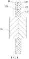
FIG. 8 is a schematic structural diagram of a partition plate provided with an electrolyte solution guide hole according to another embodiment of the present disclosure. -
FIG. 9 is a schematic structural diagram of sealed mating between a sealing member and a sealing channel according to an embodiment of the present disclosure. -
FIG. 10 is a cross-sectional view of the structure shown inFIG. 9 . -
FIG. 11 is a schematic structural diagram of sealed mating between a sealing member and a sealing channel according to another embodiment of the present disclosure. -
FIG. 12 is a front view of the structure shown inFIG. 11 . -
FIG. 13 is a cross-sectional view of the structure shown inFIG. 11 . -
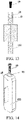
FIG. 14 is a schematic structural diagram of sealed mating between a sealing member and a sealing channel according to another embodiment of the present disclosure. -
FIG. 15 is a front view of the structure shown inFIG. 14 . -
FIG. 16 is a cross-sectional view of the structure shown inFIG. 14 . -
FIG. 17 is a schematic structural diagram of sealed mating between a sealing member and a sealing channel according to another embodiment of the present disclosure. -
FIG. 18 is a front view of the structure shown inFIG. 17 . -
FIG. 19 is a cross-sectional view of the structure shown inFIG. 17 . -
FIG. 20 is a schematic structural diagram of sealed mating between a sealing member and a sealing channel according to another embodiment of the present disclosure. -
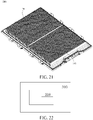
FIG. 21 is a schematic structural diagram of a battery pack according to an embodiment of the present disclosure. -
FIG. 22 is a schematic structural diagram of a battery pack according to another embodiment of the present disclosure. -
FIG. 23 is a schematic structural diagram of a battery module according to an embodiment of the present disclosure. -
FIG. 24 is a schematic structural diagram of an electric vehicle according to an embodiment of the present disclosure. -
FIG. 25 is a schematic structural diagram of an electric vehicle according to another embodiment of the present disclosure. -
FIG. 26 is a schematic structural diagram of an electric vehicle according to another embodiment of the present disclosure. - List of reference numerals:
-
Battery 100; -
Housing 11; Throughhole Separator film 112;Sub-separator film 1121;End cover 121;Partition plate 122; Through connectinghole 123;Packaging structure 124;Side surface 125;Circumferential surface 126;Electrode core assembly 13; First electrode lead-out member 131; Second electrode lead-out member 132; Accommodatingcavity 14;Electrode core connector 15;Copper connection piece 151;Aluminum connection piece 152; Electrolytesolution filling channel 16;Liquid inlet 161;Liquid outlet 162;First channel 163;Second channel 164;Third channel 165;Fourth channel 166; Blockingmember 17; Electrolytesolution guide hole 18; Sealingmember 19;Sealing ring 191;Metal ball 192;Sealing sleeve 193;Sealing channel 20;Pallet 50; -
Battery module 200;Battery pack 300; -
Electric vehicle 1000. - The following specific implementations are to be combined with the foregoing accompanying drawings to further describe the present disclosure.
- The following describes embodiments of the present disclosure in detail. Examples of the embodiments are shown in the accompanying drawings, and same or similar reference signs in all the accompanying drawings indicate same or similar components or components having same or similar functions. The embodiments described below with reference to the accompanying drawings are exemplary and used only for explaining the present disclosure, and should not be construed as a limitation on the present disclosure.
- In the description of the present disclosure, it should be understood that orientation or position relationships indicated by the terms such as "center", "longitudinal", "transverse", "length", "width", "thickness", "on", "below", "front", "back", "left", "right", "vertical", "horizontal", "top", "bottom", "inside", "outside", "axial direction", "radial direction", and "circumferential direction" are based on orientation or position relationships shown in the accompanying drawings, and are used only for ease and brevity of illustration and description, rather than indicating or implying that the mentioned apparatus or component must have a particular orientation or must be constructed and operated in a particular orientation. Therefore, such terms should not be construed as limiting of the present disclosure.
- In the present disclosure, unless otherwise explicitly specified or defined, the terms such as "install", "connect", "connection", and "fix" should be understood in a broad sense. For example, the connection may be a fixed connection, a detachable connection, or an integral connection; or the connection may be a mechanical connection or an electrical connection; a direct connection, an indirect connection through an intermediate, or internal communication between two elements or an interaction relationship between two elements. A person of ordinary skill in the art may understand the specific meanings of the foregoing terms in the present disclosure according to specific situations.
- As shown in
FIG. 1 and FIG. 2 , the present disclosure provides abattery 100. Thebattery 100 includes ahousing 11, end covers 121,partition plates 122, and a number ofelectrode core assemblies 13. The end covers 121 are arranged on two opposite ends of thehousing 11 for sealing an internal space of thehousing 11. Thepartition plates 122 are spaced apart from each other in thehousing 11 for separating the internal space of thehousing 11 into a number ofaccommodating cavities 14 successively arranged along a first direction. For example, the first direction is an X direction shown inFIG. 1 . - In the present disclosure, the internal space of the
housing 11 is separated into the number ofaccommodating cavities 14 are successively arranged along the first direction. Thepartition plates 122 may separate thehousing 11 into a number of parts inside thehousing 11, so as to form the number ofaccommodating cavities 14. Alternatively, thepartition plates 122 are arranged in thehousing 11, and separate one space arranged in thehousing 11 into the number ofaccommodating cavities 14. Contents of this section are to be specifically described below. - In this implementation, the
battery 100 may be a lithium-ion battery. The first direction is a length direction of thebattery 100. Thehousing 11 is configured to enhance strength of thebattery 100 to guarantee safe use of thebattery 100. The housing may be a plastic housing or a metal housing. When the housing is the metal housing, the housing has desirable heat dissipation performance and high strength, and may have a function of supporting itself. - In this implementation, each
electrode core assembly 13 is arranged in eachaccommodating cavity 14. Theelectrode core assembly 13 includes at least one electrode core. The number ofelectrode core assemblies 13 are successively arranged along the first direction and connected in series. - In this implementation, one
electrode core assembly 13 is arranged in eachaccommodating cavity 14. Theelectrode core assemblies 13 in two adjacent accommodatingcavities 14 are connected in series. Therefore, the number ofelectrode core assemblies 13 are successively connected in series. In other implementations, the number ofelectrode core assemblies 13 may also be arranged side by side in theaccommodating cavity 14, for example, two or more than two electrode core assemblies. - The electrode core mentioned in the present disclosure is an electrode core commonly used in the field of power batteries. The electrode core and the
electrode core assemblies 13 are internal components of thehousing 11 of thebattery 100, but cannot be understood as thebattery 100 itself. The electrode core may be formed by winding or lamination. Generally, the electrode core includes at least a positive plate, a separator, a negative plate, and electrolyte solution. The electrode core is usually a module that is not completely sealed. Therefore, thebattery 100 mentioned in the present disclosure is a single cell, which cannot be simply understood as a battery module because the battery includes a number of electrode cores. In the present disclosure, theelectrode core assembly 13 may be composed of an independent electrode core, or may include at least two electrode cores. Theelectrode core assembly 13 is formed after the at least two electrode cores are connected in parallel. - In the present disclosure, the number of
electrode core assemblies 13 are connected in series, thereby achieving a high capacity and a high voltage of thebattery 100, simplifying the manufacturing process, and reducing costs. - Generally, a number of the series-connected electrode core assemblies included in the
battery 100 may be determined according to an output voltage of eachelectrode core assembly 13, a width of the used battery pack, and an overall voltage requirement of the battery pack. For example, for a vehicle model, a battery system is required to output a voltage of 300 V, and a voltage of a conventional lithium-iron battery is 3.2 V. Therefore, in related arts, 100 batteries are required to be connected in series in the pack to meet the requirements. In the battery pack in the present disclosure, assuming that 2electrode core assemblies 13 are connected in series in the battery, it is only necessary to arrange 50batteries 100. By analogy, if 10electrode core assemblies 13 are connected in series, it is only necessary to connect 10batteries 100 in series. In this way, the design of the whole pack and the arrangement of cells are greatly simplified, which can effectively use the space and enhance space utilization. - In related arts, in order to realize the high capacity and high voltage of the battery, it is generally necessary to connect two or more than two cells in series. However, power connection between end covers of respective end portions and an external power connector is required at a junction between two adjacent cells connected in series, resulting in a relatively large number of structural members of the battery, which not only increases costs, but also increases the overall weight of the power battery pack. In addition, the structural members occupy relatively large internal space of the battery pack, resulting in a decrease in an overall capacity of the power battery pack. In addition, a number of external power connectors need to be arranged for power connection, so that internal consumption of the power battery pack in use is increased with the increased internal resistance.
- Compared with related arts, in the present disclosure, the
partition plates 122 are spaced apart from each other in thehousing 11 to separate the number ofaccommodating cavities 14 side by side inside thehousing 11. Theelectrode core assembly 13 is arranged in eachaccommodating cavity 14. Theelectrode core assemblies 13 in theaccommodating cavities 14 are connected in series. In this way, the capacity and the voltage of thebattery 100 can be effectively increased. In addition, two adjacent accommodatingcavities 14 are communicated by onepartition plate 122 in a sealed manner. In this way, a structural member of thebattery 100 may be simplified, a spacing between the two adjacentelectrode core assemblies 13 may be decreased, and internal consumption of the power battery pack is reduced. Therefore, the battery pack may have larger internal space to accommodate cells, thereby increasing the overall capacity and the voltage of the battery pack, and improving the endurance capacity of anelectric vehicle 1000 using the battery pack. - In this implementation, lengths of the
housing 11 and theelectrode core assemblies 13 both extend along the first direction. Thehousing 11 is an integrated structure extending along the first direction. - In the present disclosure, as shown in
FIG. 1 , thebattery 100 is generally a cuboid. Thebattery 100 has a length L, a width H, and a thickness D. The length L of thebattery 100 is greater than the width H, and the width H of thebattery 100 is greater than the thickness D. The length of thebattery 100 may range from 400 mm to 2500 mm. In the present disclosure, a ratio of the length L of thebattery 100 to the width H is L/H = 4-21. - It is to be noted that the
battery 100 being generally a cuboid may be understood that, thebattery 100 may be in a shape of a cuboid or a cube, or partially special-shaped but substantially in the shape of the cuboid or the cube, or has a notch, a protrusion, a chamfer, a camber, or a crook in part, but is in the shape similar to the cuboid or the cube as a whole. - In related arts, in order to increase the volume utilization of the battery pack, a size of the battery is set to be in a range of 400 mm to 2500 mm. Since the battery is too long, the internal resistance of the battery is too high if only one electrode core is arranged. As a result, a potential difference between a positive electrode and a negative electrode is excessively large, resulting in the electrolyte solution unable to work properly. According to the technical solution of the present disclosure, the battery having the length ranging from 400 mm to 2500 mm can be manufactured conveniently, and the internal resistance and the connection between structural components can be reduced, thereby further reducing the costs.
- As shown in
FIG. 3 , thepartition plate 122 includes aside surface 125 facing the adjacentelectrode core assemblies 13 and acircumferential surface 126 connected with theside surface 125. Thecircumferential surface 126 of thepartition plate 122 is mated with thehousing 11 to separate the internal space of thehousing 11 into the number ofaccommodating cavities 14. - In an implementation, referring to
FIG. 2 again, a cavity wall of theaccommodating cavity 14 among the number ofaccommodating cavities 14 on each of two ends of thebattery 100 in the first direction includes thepartition plate 122 and theend cover 121 that are arranged on the end portions of theaccommodating cavity 14, and thehousing 11 arranged between thepartition plate 122 and theend cover 121. A cavity wall of theaccommodating cavity 14 among the number ofaccommodating cavities 14 arranged in the middle of thebattery 100 in the first direction includes twoadjacent partition plates 122 arranged on end portions of theaccommodating cavity 14 and thehousing 11 arranged between the twoadjacent partition plates 122. That is to say, thepartition plates 122 separate thehousing 11 into a number of parts in thehousing 11, so as to form the number ofaccommodating cavities 14. - In the present disclosure, when the number of
electrode core assemblies 13 are connected in series, an internal short circuit occurs in a case that the electrolyte solution in differentelectrode core assemblies 13 are communicated with each other, and a relatively high potential difference (by using a lithium iron phosphate battery as an example, a potential difference ranges from 4.0 V to 7.6 V) exists among differentelectrode core assemblies 13. In this way, the electrolyte solution in the electrode core assemblies may be decomposed due to the large potential difference, which affects the performance of the battery. In order to better achieve the function of insulation, thepartition plate 122 may be made of an insulation material. That is to say, thepartition plates 122 are insulating partition plates. Therefore, thepartition plates 122 may be directly used to isolate the two adjacentelectrode core assemblies 13 to maintain the insulation between the electrode core assemblies without performing other operations. Thehousing 11 may be a metal housing having an insulated inner surface. - In another implementation, as shown in
FIG. 4 , thebattery 100 further includes aseparator film 112 arranged in thehousing 11. Thepartition plates 122 are spaced apart from each other in theseparator film 112. Thecircumferential surfaces 126 of thepartition plates 122 are mated with theseparator film 112 to separate an internal space of theseparator film 112 into a number ofaccommodating cavities 14. That is to say, theseparator film 112 is an integrated film. Thepartition plates 122 are arranged in theseparator film 112, and separate a receiving space of theseparator film 112 into the number ofaccommodating cavities 14. - In this implementation, the number of
partition plates 122 are arranged in the housing 22 of thebattery 100, to separate the space in the housing 22 into the number ofaccommodating cavities 14 spaced apart from each other along the first direction. The cavity wall of theaccommodating cavity 14 among the number ofaccommodating cavities 14 on each of two ends of thebattery 100 in the first direction includes thepartition plate 122 and theend cover 121 arranged on the end portion of theaccommodating cavity 14, and theseparator film 112 arranged between thepartition plate 122 and theend cover 121. In addition, the cavity wall of theaccommodating cavity 14 among the number ofaccommodating cavities 14 arranged in the middle of thebattery 100 in the first direction includes twoadjacent partition plates 122 arranged on the end portions of theaccommodating cavity 14 and theseparator film 112 arranged between the twoadjacent partition plates 122. - In another implementation, as shown in
FIG. 5 , thebattery 100 further includes theseparator film 112 arranged inside thehousing 11. Theseparator film 112 includes a number ofsub-separator films 1121 arranged along the first direction and in a one-to-one correspondence with the number ofaccommodating cavities 14. Two opposite ends of eachsub-separator film 1121 are mated with thepartition plates 122 on two ends of the correspondingaccommodating cavity 14, or thepartition plates 122 are mated with the end covers 121 to form the correspondingaccommodating cavity 14. Two adjacent accommodatingcavities 14 share onepartition plate 122. - In this implementation, the number of
partition plates 122 are arranged in the housing 22 of thebattery 100, to separate the space in the housing 22 into the number ofaccommodating cavities 14 spaced apart from each other along the first direction. The cavity wall of theaccommodating cavity 14 among the number ofaccommodating cavities 14 arranged in the middle of thebattery 100 in the first direction includes thecorresponding sub-separator film 1121 and twopartition plates 122 arranged on end portions of thecorresponding sub-separator film 1121. The cavity wall of theaccommodating cavity 14 among the number ofaccommodating cavities 14 arranged on each of the two ends of thebattery 100 in the first direction includes the correspondingsub-separator films 1121 and thepartition plate 122 and theend cover 121 that are arranged on the end portions of thecorresponding sub-separator film 1121. - The number of
sub-separator films 1121 are a number of independent parts separated from each other. That is to say, theseparator film 112 is a separated-type separator film. Eachsub-separator film 1121 is a cylindrical structure having two open ends. Theelectrode core assemblies 13 are arranged inside thecylindrical sub-separator film 1121. Thepartition plates 122 or the end covers 121 are sealed to the open ends of thecorresponding separator film 112. - In the present disclosure, a manner in which the
separator film 112 is sealed to thepartition plates 122 or the end covers 121 and a specific structure are not specially limited. For example, when thepartition plate 122 or theend cover 121 is made of a plastic material, and theseparator film 112 is made of plastic, theseparator film 112 may be sealed to thepartition plates 122 or the end covers 121 by hot melting. - In the present disclosure, the number of
electrode core assemblies 13 are connected in series. Different voltages among differentelectrode core assemblies 13 may cause an excessively low local potential of the housing such as an aluminum housing. At this point, lithium ions may be easily embedded in an outside of the housing to form an aluminum-lithium alloy and corrode the aluminum housing. In the present disclosure, theseparator film 112 is arranged between thehousing 11 and theelectrode core assembly 13, so as to effectively prevent contact between the electrolyte solution and thehousing 11. - The
separator film 112 has certain insulating property and resistance to electrolyte solution corrosion. A material of theseparator film 112 is not specially limited, as long as the material has the insulating property and does not react with the electrolyte solution. In some embodiments, the material of theseparator film 112 may include polypropylene (PP), polyethylene (PE), or a multilayer composite film. For example, in some embodiments, the multilayer composite film includes an inner layer, an outer layer, and a middle layer between the inner layer and the outer layer. The inner layer includes the plastic material. For example, the inner layer may be made of a material that is less reactive with the electrolyte solution in theseparator film 112 and has the insulating property, for example, PP or PE. The middle layer includes a metal material, so as to prevent permeation of water vapor outside thebattery 100 and also prevent the leakage of the electrolyte solution inside the battery. Aluminum foil, stainless steel foil, copper foil, and the like are preferably used as the metal layer. The outer layer is a protective layer, which is usually made of polyester having a high melting point or a nylon material, and has a strong mechanical property. In this way, an external force is prevented from damaging thebattery 100, thereby protecting thebattery 100. In some implementations, theseparator film 112 further has certain flexibility, which facilitates the molding and machining of thebattery 100 and prevents the battery from being pierced. - In the present disclosure, in order to inject the electrolyte solution into the
accommodating cavities 14 where theelectrode core assemblies 13 are arranged, as shown inFIG. 3 , thepartition plate 122 is provided with an electrolytesolution filling channel 16. The electrolytesolution filling channel 16 is in communication with theaccommodating cavity 14 on at least one side of thepartition plate 122, and is configured for electrolyte solution to be injected into theaccommodating cavity 14 from an outside of thebattery 100. The electrolytesolution filling channel 16 is in a closed state upon completion of the electrolyte solution filling, to prevent communication between theaccommodating cavity 14 and the outside of thebattery 100. It may be understood that the electrolytesolution filling channel 16 in communication with theaccommodating cavity 14 on one side of theend cover 121 may also be provided on the end cover according to actual conditions. - Two ends of the electrolyte
solution filling channel 16 are respectively formed as aliquid inlet 161 and aliquid outlet 162. Theliquid inlet 161 is arranged on thecircumferential surface 126 of thepartition plate 122 where the liquid inlet is arranged. Theliquid outlet 162 is arranged on theside surface 125 of thepartition plate 122 where the liquid outlet is arranged. The electrolyte solution is injected into the electrolytesolution filling channel 16 through theliquid inlet 161, and injected into theaccommodating cavity 14 through theliquid outlet 162. - In the present disclosure, a shape of the electrolyte
solution filling channel 16 may be flexibly configured. For example, electrolyte solution filling channel may be an arcuate or curved cylindrical channel, or may be an L-shaped channel. - Referring to
FIG. 1 andFIG. 3 again, in this implementation, a throughhole 111 is provided at a position of thehousing 11 corresponding to the electrolytesolution filling channel 16 on thepartition plate 122. The throughhole 111 is configured to communicate the electrolytesolution filling channel 16 with the outside of thebattery 100. - It may be understood that, when the
integrated separator film 112 is arranged in thehousing 11, as shown inFIG. 4 , a throughhole 1122 is also provided at a position of theseparator film 112 corresponding to the electrolytesolution filling channel 16 on thepartition plate 122. The throughhole 1122 is configured to communicate the electrolytesolution filling channel 16 with the outside of thebattery 100. - In the present disclosure, the through holes are provided on the
housing 11 of thebattery 100 or at the positions of thehousing 11 and theseparator film 112 corresponding to the electrolytesolution filling channel 16 on thepartition plate 122. In this way, the electrolyte solution may be injected into each individual accommodatingcavity 14 after thebattery 100 is assembled. Therefore, the problem such as the electrolyte solution filling of the battery including the number of electrode core assemblies connected in series is effectively resolved. - It may be understood that, after the electrolyte solution is injected into the
accommodating cavity 14, the electrolytesolution filling channel 16 is required to be sealed. In an implementation, as shown inFIG. 3 , thebattery 100 further includes a blockingmember 17. The blockingmember 17 is configured to seal the electrolytesolution filling channel 16 upon completion of the electrolyte solution filling. At least part of the blockingmember 17 may be arranged in the electrolytesolution filling channel 16. - In another implementation, a protrusion may protrude outward from the
partition plate 122 and is made of plastic. Theliquid inlet 161 is arranged on the protrusion. Theliquid inlet 161 is sealed by hot melting upon completion of the electrolyte solution filling. - In the present disclosure, two
adjacent housings 11 are sealed to each other by using thepartition plate 122. The electrolytesolution filling channel 16 is provided on thepartition plate 122. In this way, once the electrolyte solution in one of theaccommodating cavities 14 leaks, other accommodatingcavities 14 remain intact. Therefore, the safety problem caused by the leakage of the electrolyte solution will not occur. Upon completion of the electrolyte solution filling, the electrolytesolution filling channel 16 on thepartition plate 122 of the cavity wall of theaccommodating cavity 14 is in a sealed state. Therefore, on the one hand, the electrolyte solution in theaccommodating cavity 14 does not flow out from theaccommodating cavity 14 to come into contact with thehousing 11 to cause an internal short circuit. On the other hand, the electrolyte solution does not flow between adjacentaccommodating cavities 14, which does not affect each other, and is not decomposed due to the excessively large potential difference, thereby ensuring the safety and the service life of thebattery 100. - In the field of power batteries, the consistency of working conditions of cells is very important, which directly affects the performance of the entire battery pack. Similarly, the consistency of working conditions of the electrode core assemblies in the battery will also affect the overall performance of each cell, and affect the performance of the entire battery pack. However, an amount of the electrolyte solution inside the battery will affect the performance of the battery, such as a capacity, activity, and the like. In the present disclosure, the electrolyte
solution filling channel 16 is provided on thepartition plate 122. In a case that it is ensured that the electrolyte solution can timely and effectively infiltrate the electrode core assemblies, the forming process of thebattery 100 may be optimized. - With regard to a manner in which the electrolyte
solution filling channel 16 is arranged, in an implementation, as shown inFIG. 3 , one electrolytesolution filling channel 16 may be communicated with theaccommodating cavity 14. - It is to be noted that, when the electrolyte
solution filling channel 16 is only communicated with one accommodatingcavity 14, the electrolytesolution filling channel 16 is required to be provided on eachpartition plate 122. By forming a number of openings and performing electrolyte solution filling a number of times, eachaccommodating cavity 14 accommodating theelectrode core assembly 13 can have an individual channel for the electrolyte solution to be injected. In this way, a shortest electrolyte solution filling path may be achieved, and the electrolyte solution can timely flow to the correspondingaccommodating cavity 14 through the electrolytesolution filling channel 16, thereby ensuring that the electrolyte solution can timely and effectively infiltrate theelectrode core assembly 13. In addition, a content of the electrolyte solution in eachaccommodating cavity 14 may be accurately controlled by arranging a number of electrolytesolution filling channels 16, so as to ensure the consistency of the electrolyte solution in the number ofaccommodating cavities 14. - Optionally, in another implementation, as shown in
FIG. 6 , the electrolytesolution filling channel 16 may be simultaneously communicated with the two adjacent accommodatingcavities 14. - Speci fically, the electrolyte
solution filling channel 16 includes afirst channel 163 and asecond channel 164. Thefirst channel 163 extends through thepartition plate 122 where the first channel is arranged, and is configured to communicate the two adjacent accommodatingcavities 14 on two sides of thepartition plate 122. Thesecond channel 164 is configured to communicate thefirst channel 163 with the outside of thebattery 100. That is to say, thecircumferential surface 126 of thepartition plate 122 is provided with oneliquid inlet 161. Theliquid outlet 162 is provided on both side surfaces 125 of thepartition plate 122. - The
battery 100 further includes a blockingmember 17. The blockingmember 17 is configured to seal thesecond channel 164 upon completion of the electrolyte solution filling, to block communication between thesecond channel 164 and the outside. The blockingmember 17 is further configured to block at least partial area of thefirst channel 163, to block the communication between the two adjacent accommodatingcavities 14 through thefirst channel 163. - It is to be noted that, when the
accommodating cavities 14 on two sides of thepartition plate 122 are simultaneously communicated through the electrolytesolution filling channel 16 on thepartition plate 122, it is not necessary to provide the electrolytesolution filling channel 16 on eachpartition plate 122. The electrolytesolution filling channel 16 may be provided everyother partition plate 122. - In this implementation, since the
accommodating cavities 14 on the two sides of thepartition plate 122 are at a relatively small distance from each other, the electrolyte solution may be simultaneously injected into the adjacent accommodatingcavities 14 on the two sides of thepartition plate 122 through the electrolytesolution filling channel 16 on thepartition plate 122. Due to a relatively short infiltration path of the electrolyte solution, the electrolyte solution may still timely and effectively infiltrate theelectrode core assemblies 13 on two sides. - Optionally, in another implementation, a number of the electrolyte
solution filling channels 16 on eachpartition plate 122 may be 1 or more. - For example, as shown in
FIG. 7 , the electrolytesolution filling channel 16 includes athird channel 165 and afourth channel 166 independent of each other. That is to say, two electrolytesolution filling channels 16 are provided on thepartition plate 122. Thethird channel 165 is in communication with theaccommodating cavity 14 on one side of thepartition plate 122 where the third channel is arranged. Thefourth channel 166 is in communication with theaccommodating cavity 14 on an other side of thepartition plate 122 where the fourth channel is arranged. - Optionally, in another implementation, each
partition plate 122 is provided with the electrolytesolution filling channel 16. In this way, eachaccommodating cavity 14 corresponds to one electrolytesolution filling channel 16. Therefore, the amount of the electrolyte solution injected into eachaccommodating cavity 14 can be accurately controlled, thereby ensuring the consistency of the electrolyte solution. - In an implementation, as shown in
FIG. 8 , at least onepartition plate 122 is provided with an electrolytesolution guide hole 18. The electrolytesolution guide hole 18 is configured to communicate the two adjacent accommodatingcavities 14 on the two sides of thepartition plate 122 where the electrolyte solution guide hole is arranged. The electrolytesolution guide hole 18 extends through two opposite side surfaces 125 of thepartition plate 122. - Specifically, in some implementations, the electrolyte
solution filling channel 16 and the electrolytesolution guide hole 18 are provided ondifferent partition plates 122. One of the twoadjacent partition plates 122 is provided with the electrolytesolution filling channel 16, and an other of thepartition plates 122 is provided with the electrolytesolution guide hole 18. - Optionally, in some implementations, the electrolyte
solution filling channel 16 and the electrolytesolution guide hole 18 are provided ondifferent partition plates 122. A part of the number ofpartition plates 122 is provided with the electrolytesolution filling channel 16. The electrolytesolution filling channel 16 is in communication with the two adjacent accommodatingcavities 14 on the two sides of thepartition plate 122 where the electrolyte solution filling channel is arranged. An other part of thepartition plates 122 is provided with the electrolytesolution guide hole 18. - Optionally, in some implementations, a part of the number of
partition plates 122 is provided with both the electrolytesolution filling channel 16 and the electrolytesolution guide hole 18 in communication with the electrolytesolution filling channel 16, and an other part of thepartition plates 122 is provided with the electrolytesolution guide hole 18. - In an implementation, as shown in
FIG. 9 , thebattery 100 further includes a sealingmember 19. The sealingmember 19 can block the electrolytesolution guide hole 18 upon completion of the electrolyte solution filling of thebattery 100, to cause the electrolytesolution guide hole 18 to be in a closed state, so as to block the communication between the two adjacent accommodatingcavities 14 through the electrolytesolution guide hole 18. That is to say, upon completion of the electrolyte solution filling, the sealingmember 19 seals the electrolytesolution guide hole 18 to isolate the two adjacent accommodatingcavities 14. In this way, the electrolyte solution does not flow between the adjacent accommodatingcavities 14, so as not to affect each other, and the electrolyte solution is not decomposed due to the excessively large potential difference, thereby ensuring the safety and the service life of thebattery 100. - In an implementation, as shown in
FIG. 9 andFIG. 10 , thecircumferential surface 126 of thepartition plate 122 is further provided with a sealingchannel 20 communicated with the electrolytesolution guide hole 18 and extending through the electrolytesolution guide hole 18. The sealingmember 19 can block the electrolytesolution guide hole 18 under the action of an external force. - In some implementations, the sealing
member 19 is a sealing plug, and a shape of the sealingchannel 20 is mated with a shape of the sealing plug. - As shown in
FIG. 9 andFIG. 10 , the sealingmember 19 is a cuboid structure. Optionally, the sealingmember 19 may also be a cylindrical structure or a cylindrical structure having an elliptical cross-section. The shape of the sealingchannel 20 may be flexibly configured according to the shape of the sealingmember 19. - Optionally, as shown in
FIG. 11, FIG. 12 , andFIG. 13 , the sealingmember 19 is a wedge-shaped block structure. - Optionally, as shown in
FIG. 14 ,FIG. 15, and FIG. 16 , an inner wall of the sealingchannel 20 is provided with threads. The sealingmember 19 is a cylinder or a screw having a threaded surface. - Optionally, as shown in
FIG. 17, FIG. 18 , andFIG. 19 , the sealingmember 19 is a columnar structure, and anelastic sealing ring 191 is sleeved on a position corresponding to the electrolytesolution guide hole 18 in a sealed state. - In some implementations, as shown in
FIG. 20 , the sealingmember 19 is a sealing ball, and includes ametal ball 192 and a sealingsleeve 193 wrapped around an outer surface of the metal ball. The sealing ball is arranged in the sealingchannel 20 by means of interference fit. - In some implementations, before the electrolyte solution filling, during the electrolyte solution filling, or during formation of the
battery 100 after the electrolyte solution filling, the sealingmember 19 is in a first situation, and the electrolytesolution guide hole 18 is in an open state to communicate the two adjacent accommodatingcavities 14 on two sides of thepartition plate 122 where the electrolyte solution guide hole is arranged. After the electrolyte solution filling or during formation of thebattery 100 after the electrolyte solution filling, the sealingmember 19 is switched from the first situation to a second situation. The sealingmember 19 blocks the electrolytesolution guide hole 18 to cause the electrolytesolution guide hole 18 to be in the closed state, so as to block the communication between the two adjacent accommodatingcavities 14 through the electrolytesolution guide hole 18. The sealingmember 19 is switchable between the first situation and the second situation. - Specifically, a first position and a second position are formed in the sealing
channel 20. The sealingmember 19 is movable between the first position and the second position under the action of the external force. The first situation is that the sealingmember 19 is arranged at the first position. The second situation is that the sealingmember 19 is arranged at the second position. The external force is selected from one or more of gravity, an electromagnetic force, an inertial force, or a thermal force. - Referring to
FIG. 2 andFIG. 3 again, in the present disclosure, eachelectrode core assembly 13 includes a first electrode lead-out member 131 and a second electrode lead-out member 132 that are configured to lead out currents. In this implementation, the first electrode lead-out member 131 and the second electrode lead-out member 132 are respectively arranged on two opposite sides of theelectrode core assembly 13 along the first direction. - According to the present disclosure, all of the
housings 11 and all of theelectrode core assemblies 13 are arranged along the first direction, and the first electrode lead-out member 131 and the second electrode lead-out member 132 of theelectrode core assembly 13 are respectively arranged on the two opposite sides of theelectrode core assembly 13 along the first direction. That is to say, a "head to head" arrangement mode is adopted between theelectrode core assemblies 13. The arrangement mode can conveniently realize series connection between the two adjacentelectrode core assemblies 13 in thebattery 100, and the connection structure is simple. In addition, thebattery 100 having a relatively large length may be conveniently manufactured by using the arrangement mode. - Generally, each
electrode core assembly 13 includes a first electrode lead-out member 131 and a second electrode lead-out member 132 that are configured to lead out currents. If theelectrode core assembly 13 includes only one electrode core, the first electrode lead-out member 131 and the second electrode lead-out member 132 may be respectively a positive tab and a negative tab of the electrode core, or respectively the negative tab and the positive tab. If theelectrode core assembly 13 includes a number of electrode cores, the first electrode lead-out member may be a lead-out member formed by combining and soldering the positive tabs. The second electrode lead-out member may be a lead-out member formed by combining and soldering the negative tabs. Alternatively, the first electrode lead-out member may be a lead-out member formed by combining and soldering the negative tabs. The second electrode lead-out member may be a lead-out member formed by combining and soldering the positive tabs. "First" and "second" in the first electrode lead-out member 131 and the second electrode lead-out member 132 are merely used for name distinction, and not for limiting numbers. For example, there may be one or more first electrode lead-out members. - The series connection mode provided in this implementation may be series connection between the adjacent
electrode core assemblies 13. A specific implementation may be that current lead-out members on the adjacentelectrode core assemblies 13 are directly connected or may be electrically connected by using an extra conductive component. That is to say, theelectrode core assemblies 13 in the two adjacent accommodatingcavities 14 may be directly or indirectly electrically connected. - Specifically, in an implementation, the
battery 100 further includes anelectrode core connector 15. Theelectrode core connector 15 extends through thepartition plate 122. For example, a through connectinghole 123 is provided on thepartition plate 122. Theelectrode core connector 15 extends through the through connectinghole 123. That is to say, theelectrode core connector 15 penetrates from one side to an other side of the through connectinghole 123. - In an implementation, the first electrode lead-
out member 131 of one of theelectrode core assemblies 13 in the two adjacent accommodatingcavities 14 is electrically connected with the second electrode lead-out member 132 of an other of theelectrode core assemblies 13 by using theelectrode core connector 15. That is to say, theelectrode core assemblies 13 in the two adjacent accommodatingcavities 14 are indirectly connected. - In an implementation, the two adjacent
electrode core assemblies 13 are connected by theelectrode core connector 15, so as to provide a larger design space for theelectrode core connector 15, increase a flow area, and reduce the internal resistance of thebattery 100. - In some implementations, the
electrode core connector 15 may be a sheet structure. Optionally, in some implementations, theelectrode core connector 15 may be a columnar structure. - The first electrode lead-
out member 131 and the second electrode lead-out member 132 may be directly soldered to theelectrode core connector 15 in thecorresponding partition plate 122. Compared with the series connection between the existing cells, soldering procedures and steps are simplified, the risk that may be caused by poor soldering is reduced, and the overall safety and reliability of the battery are enhanced. - As shown in
FIG. 3 , theelectrode core connector 15 includes acopper connection piece 151 and analuminum connection piece 152 that are electrically connected with each other. Since a difference exists between a potential of copper vs. lithium and a potential of aluminum vs. lithium, corrosion easily occurs if a junction of thecopper connection piece 151 and thealuminum connection piece 152 comes into contact with the electrolyte solution. In an implementation, a position where thecopper connection piece 151 is electrically connected with thealuminum connection piece 152 is arranged inside thepartition plate 122. - In order to prevent, from being corroded by the electrolyte solution, the position where the
copper connection piece 151 is electrically connected with thealuminum connection piece 152, and in order to isolate theaccommodating cavities 14 on two sides of thepartition plate 122 to block interpenetration of the electrolyte solution in theaccommodating cavities 14 on the two sides of thepartition plate 122, in some embodiments, as shown inFIG. 7 , thebattery 100 further includes apackaging structure 124 arranged in the through connectinghole 123. Thepackaging structure 124 is configured to package theelectrode core connector 15 in the through connectinghole 123. In addition, thepackaging structure 124 can seal the through connectinghole 123. In this way, a position where thecopper connection piece 151 is in contact with thealuminum connection piece 152 is sealed inside thepartition plate 122, to prevent the position from being exposed to an internal space of thebattery 100, especially prevent the position from being in contact with the electrolyte solution, so as to prevent, from being corroded, the position where the copper connection piece is connected with the aluminum connection piece. - In the present disclosure, the
packaging structure 124 is only required to have the sealing performance and be resistant to electrolyte solution corrosion and insulated. For example, the packaging structure may be a rubber stopper. - In the mounting solution by using the
electrode core connector 15 provided in the above embodiments, secondary packaging is required to be performed on the through connectinghole 123, which is not convenient to operate. In addition, during the secondary packaging, selected materials used for thepackaging structure 124 are complex, and may affect the electrolyte solution inside thebattery 100. In view of this, in another embodiment, as shown inFIG. 3 andFIG. 6 , a solution of integrally forming theelectrode core connector 15 and thepartition plate 122 by means of injection molding is provided. In the solution, theelectrode core connector 15 and thepartition plate 122 are integrally formed by means of the injection molding. Specifically, theelectrode core connector 15 is first manufactured, and then thepartition plate 122 is formed outside theelectrode core connector 15 by means of the injection molding. In order to better achieve a sealing effect of thepartition plate 122, during the integral injection molding, a position where plastic is in contact with metal is formed by using an EPI molding technology. For example, a nano-plastic layer is sintered with a metal surface, such as PPE, PPS, and the like, and then integral injection molding is performed on a plastic member. By using the method, the metal layer and the plastic layer can be bonded together more effectively, thereby improving the sealing performance of the entire structural component. During the assembly, theelectrode core assembly 13 and theelectrode core connector 15 are directly connected without needing to seal through holes, thereby reducing the risk while simplifying the process. - In yet another implementation, the first electrode lead-
out member 131 of one of theelectrode core assemblies 13 in the two adjacent accommodatingcavities 14 may be electrically connected with the second electrode lead-out member 132 of an other of theelectrode core assemblies 13. The junction of the first electrode lead-out member 131 and the second electrode lead-out member is arranged in thepartition plate 122 between the twoelectrode core assemblies 13. That is to say, the first electrode lead-out member 131 and the second electrode lead-out member 132 are directly electrically connected. The junction of the first electrode lead-out member 131 and the second electrode lead-out member 132 is a position where the first electrode lead-out member 131 and the second electrode lead-out member 132 are connected with each other. - Similar to the foregoing implementation, in order to facilitate the electrical connection between the first electrode lead-
out member 131 and the second electrode lead-out member 132, the through connecting hole is provided on thepartition plate 122. The junction of the first electrode lead-out member 131 and the second electrode lead-out member 132 is arranged in the through connecting hole of thepartition plate 122 between the twoelectrode core assemblies 13. - In order to block interpenetration of the electrolyte solution in the
accommodating cavities 14 of theelectrode core assemblies 13 on the two sides of thepartition plate 122, thebattery 100 further includes the packaging structure arranged in the through connecting hole. The packaging structure is configured to package the junction in the through connecting hole, and seals the through connecting hole. In this way, the first electrode lead-out member and the second electrode lead-out member are sealed to thepartition plate 122, to prevent movement of the electrolyte solution in the two adjacentelectrode core assemblies 13 on the two sides of thepartition plate 122. - In this implementation, since the two
adjacent housings 11 share onepartition plate 122, a spacing between the twoelectrode core assemblies 13 is greatly reduced. Compared with the connection between twobatteries 100 and an external power connector by using the first electrode lead-out member 131 and the second electrode lead-out member 132 in related arts, the subsequent assembling process of the battery pack is simplified. In addition, the used materials are reduced, and a weight is reduced. - In the present disclosure, the
battery 100 may further include other structures, such as an explosion-proof valve, a current interrupt device, and the like. For the other structures, reference may be made to general settings in related arts, and the details are not described herein again. - As shown in
FIG. 23 , the present disclosure further provides a battery module. The battery module includes thebattery 100 according to any of the above embodiments. By using the battery module provided in the present disclosure, fewer assembling processes are required, and costs are relatively low. - As shown in
FIG. 21 and FIG. 22 , the present disclosure further provides abattery pack 300, including apallet 50 and thebattery 100 or thebattery module 200 according to any of the above embodiments. Thebattery 100 or thebattery module 200 is arranged inside thepallet 50. By using the battery pack provided in the present disclosure, fewer assembling processes are required, costs are relatively low, and energy density is high. As shown inFIG. 24 andFIG. 26 , the present disclosure further provides anelectric vehicle 1000 using the above battery pack as a power source, including thebattery 100, thebattery module 200, or thebattery pack 300. Theelectric vehicle 1000 can have a high endurance capacity and relatively low costs by using thebattery pack 300 provided in the present disclosure. - In the description of the present disclosure, it should be noted that unless otherwise explicitly specified or defined, the terms such as "mount", "install", "connect", and "connection" should be understood in a broad sense. For example, the connection may be a fixed connection, a detachable connection, or an integral connection; or the connection may be a mechanical connection or an electrical connection; or the connection may be a direct connection, an indirect connection through an intermediary, or internal communication between two components. A person of ordinary skill in the art may understand the specific meanings of the foregoing terms in the present disclosure according to specific situations.
- In description of this specification, description of reference terms such as "an embodiment", "specific embodiments", or "an example", means including specific features, structures, materials, or features described in the embodiment or example in at least one embodiment or example of the present disclosure. In this specification, schematic descriptions of the foregoing terms do not necessarily point at a same embodiment or example. In addition, the described specific features, structures, materials, or characteristics may be combined in a proper manner in any one or more of the embodiments or examples.
- Although the embodiments of the present disclosure have been shown and described, persons of ordinary skill in the art should understand that various changes, modifications, replacements and variations may be made to the embodiments without departing from the principles and spirit of the present disclosure, and the scope of the present disclosure is as defined by the appended claims and their equivalents.
Claims (24)
- A battery, comprising a housing, end covers, partition plates, and a plurality of electrode core assemblies; whereinthe end covers are arranged on two opposite ends of the housing for sealing an internal space of the housing;the partition plates are spaced apart from each other in the housing for separating the internal space of the housing into a plurality of accommodating cavities successively arranged along a first direction;each electrode core assembly is arranged in each of the accommodating cavities; the plurality of electrode core assemblies are successively arranged along the first direction and connected in series;each partition plate is provided with an electrolyte solution filling channel; the electrolyte solution filling channel is in communication with the accommodating cavity on at least one side of the partition plate, and is configured for electrolyte solution to be injected into the accommodating cavity from an outside of the battery; the electrolyte solution filling channel is in a closed state upon completion of the electrolyte solution filling, to prevent communication between the accommodating cavity and the outside of the battery;a through hole is provided at a position of the housing corresponding to the electrolyte solution filling channel on the partition plate; and the through hole of the housing is configured to communicate the electrolyte solution filling channel with the outside of the battery.
- The battery according to claim 1, wherein the housing is an integrated structure extending along the first direction; the partition plate comprises side surfaces facing adjacent electrode core assemblies and a circumferential surface connected with the side surfaces; the circumferential surface of the partition plate is mated with the housing to separate the internal space of the housing into the plurality of accommodating cavities;
a cavity wall of the accommodating cavity among the plurality of accommodating cavities arranged in the middle of the battery in the first direction comprises two adjacent partition plates arranged on end portions of the accommodating cavity and the housing arranged between the two adjacent partition plates; and a cavity wall of the accommodating cavity among the plurality of accommodating cavities arranged on each of two ends of the battery in the first direction comprises the partition plate and the end cover that are arranged on the end portions of the accommodating cavity and the housing arranged between the partition plate and the end cover. - The battery according to claim 1 or 2, wherein the housing is an integrated structure extending along the first direction; the partition plate comprises the side surfaces facing the adjacent electrode core assemblies and the circumferential surface connected with the side surface;the battery further comprises a separator film arranged in the housing; the partition plates are spaced apart from each other in the separator film; the circumferential surfaces of the partition plates are mated with the separator film to separate an internal space of the separator film into a plurality of accommodating cavities;the cavity wall of the accommodating cavity among the plurality of accommodating cavities arranged in the middle of the battery in the first direction comprises two adjacent partition plates arranged on end portions of the accommodating cavity and the separator film arranged between the two adjacent partition plates; a cavity wall of the accommodating cavity among the plurality of accommodating cavities arranged on each of two ends of the battery in the first direction comprises the partition plate and the end cover that are arranged on the end portions of the accommodating cavity and the separator film arranged between the partition plate and the end cover;a through hole is provided at a position of the separator film corresponding to the electrolyte solution filling channel on the partition plate; and the through hole of the separator film is configured to communicate the electrolyte solution filling channel with the outside of the battery.
- The battery according to any of claims 1 to 3, wherein the housing is an integrated structure extending along the first direction; the battery further comprises the separator film arranged inside the housing; the separator film comprises a plurality of sub-separator films arranged along the first direction and in a one-to-one correspondence with the plurality of accommodating cavities; two opposite ends of each of the sub-separator films are mated with the partition plates on two ends of the corresponding accommodating cavity, or the partition plates are mated with the end covers to form the corresponding accommodating cavity; two adjacent accommodating cavities share one partition plate;
the cavity wall of the accommodating cavity among the plurality of accommodating cavities arranged in the middle of the battery in the first direction comprises the corresponding sub-separator film and the two partition plates arranged on end portions of the corresponding sub-separator film; and the cavity wall of the accommodating cavity among the plurality of accommodating cavities arranged on each of the two ends of the battery in the first direction comprises the corresponding sub-separator film and the partition plate and the end cover that are arranged on the end portions of the corresponding sub-separator film. - The battery according to any of claims 1 to 4, wherein the electrolyte solution filling channel comprises a first channel and a second channel; the first channel extends through the partition plate where the first channel is arranged, and is configured to communicate two adjacent accommodating cavities on two sides of the partition plate; and the second channel is configured to communicate the first channel with the outside of the battery.
- The battery according to claim 5, further comprising a blocking member, wherein the blocking member is configured to seal the second channel upon completion of the electrolyte solution filling, to block communication between the second channel and the outside of the battery.
- The battery according to claim 5, further comprising a blocking member, wherein the blocking member is configured to block at least part of the first channel, to block the communication between the two adjacent accommodating cavities through the first channel.
- The battery according to any of claims 1 to 7, wherein the electrolyte solution filling channel comprises a third channel and a fourth channel that are independent of each other; the third channel is in communication with the accommodating cavity on one side of the partition plate where the third channel is arranged; and the fourth channel is in communication with the accommodating cavity on an other side of the partition plate where the fourth channel is arranged.
- The battery according to any of claims 1 to 8, wherein each partition plate is provided with the electrolyte solution filling channel.
- The battery according to any of claims 1 to 9, wherein at least one partition plate is provided with an electrolyte solution guide hole; and the electrolyte solution guide hole is configured to communicate the two adjacent accommodating cavities on two sides of the partition plate where the electrolyte solution guide hole is arranged.
- The battery according to claim 10, wherein the electrolyte solution filling channel and the electrolyte solution guide hole are provided on different partition plates; one of the two adjacent partition plates is provided with the electrolyte solution filling channel; and an other of the partition plates is provided with the electrolyte solution guide hole; orthe electrolyte solution filling channel and the electrolyte solution guide hole are provided on different partition plates; a part of the plurality of partition plates is provided with the electrolyte solution filling channel; the electrolyte solution filling channel is in communication with the two adjacent accommodating cavities on the two sides of the partition plate where the electrolyte solution filling channel is arranged; and an other part of the partition plates is provided with the electrolyte solution guide hole; orthe electrolyte solution filling channel and the electrolyte solution guide hole are provided on different partition plates; a part of the plurality of partition plates is provided with the electrolyte solution filling channel and the electrolyte solution guide hole in communication with the electrolyte solution filling channel; and an other part of the partition plates is provided with the electrolyte solution guide hole.
- The battery according to any of claims 1 to 4, further comprising a blocking member, wherein the blocking member is configured to seal the electrolyte solution filling channel upon completion of the electrolyte solution filling.
- The battery according to any of claims 1 to 12, wherein two ends of the electrolyte solution filling channel are formed as a liquid inlet and a liquid outlet; the electrolyte solution is injected into the electrolyte solution filling channel through the liquid inlet, and injected into the accommodating cavity through the liquid outlet;
a protrusion protrudes outward from the partition plate and is made of plastic; and the liquid inlet is arranged on the protrusion, and is sealed by hot melting upon completion of the electrolyte solution filling. - The battery according to any of claims 10 to 13, further comprising a sealing member, wherein the sealing member is configured to cause the electrolyte solution guide hole to be in a closed state upon completion of the electrolyte solution filling, to block the communication between the two adjacent accommodating cavities through the electrolyte solution guide hole.
- The battery according to claim 14, wherein the partition plate comprises the side surfaces facing the adjacent electrode core assemblies and the circumferential surface connected with the side surfaces;the electrolyte solution guide hole extends through the two opposite side surfaces of the partition plate;the circumferential surface of the partition plate is further provided with a sealing channel communicated with the electrolyte solution guide hole and extending through the electrolyte solution guide hole; and the sealing member is configured to enter the electrolyte solution guide hole through the sealing channel under an action of an external force, to block the electrolyte solution guide hole.
- The battery according to claim 15, wherein the sealing member is a sealing plug; and a shape of the sealing channel matches a shape of the sealing plug.
- The battery according to claim 16, wherein the sealing member is a cuboid structure, a cylindrical structure, a cylindrical structure having an elliptical cross-section, or a wedge-shaped block structure; oran inner wall of the sealing channel is provided with threads; and the sealing plug is a cylinder or a screw having a threaded surface; orthe sealing member is a columnar structure; and an elastic sealing ring is sleeved on a position of the sealing member corresponding to the electrolyte solution guide hole.
- The battery according to claim 15, wherein the sealing member is a sealing ball, and comprises a metal ball and a sealing sleeve wrapped around an outer surface of the metal ball.
- The battery according to any of claims 14 to 18, wherein before the electrolyte solution filling, during the electrolyte solution filling, or during formation of the battery after the electrolyte solution filling, the sealing member is in a first situation; the electrolyte solution guide hole is in an open state to communicate the two adjacent accommodating cavities on two sides of the partition plate where the electrolyte solution guide hole is arranged; after the electrolyte solution filling or during formation of the battery after the electrolyte solution filling, the sealing member is switched from the first situation to a second situation; the sealing member blocks the electrolyte solution guide hole to cause the electrolyte solution guide hole to be in the closed state, so as to block the communication between the two adjacent accommodating cavities through the electrolyte solution guide hole; and the sealing member is switchable between the first situation and the second situation.
- The battery according to claim 19, wherein a first position and a second position are formed in the sealing channel; the sealing member is movable between the first position and the second position under the action of the external force;
the first situation is that the sealing member is at the first position; and the second situation is that the sealing member is at the second position. - The battery according to claim 20, wherein the external force is selected from one or more of gravity, an electromagnetic force, an inertial force, or a thermal force.
- A battery module, comprising the battery according to any of claims 1 to 21.
- A battery pack, comprising the battery according to any of claims 1 to 21 or the battery module according to claim 22.
- An electric vehicle, comprising the battery pack according to claim 23, or the battery module according to claim 22, or the battery according to any of claims 1 to 21.
Applications Claiming Priority (2)
| Application Number | Priority Date | Filing Date | Title |
|---|---|---|---|
| CN201911171817.4A CN112838325B (en) | 2019-11-22 | 2019-11-22 | A battery, battery module, battery pack and electric vehicle |
| PCT/CN2020/129852 WO2021098739A1 (en) | 2019-11-22 | 2020-11-18 | Battery, battery module, battery pack and electric vehicle |
Publications (2)
| Publication Number | Publication Date |
|---|---|
| EP4050709A1 true EP4050709A1 (en) | 2022-08-31 |
| EP4050709A4 EP4050709A4 (en) | 2023-10-18 |
Family
ID=75922344
Family Applications (1)
| Application Number | Title | Priority Date | Filing Date |
|---|---|---|---|
| EP20890023.3A Pending EP4050709A4 (en) | 2019-11-22 | 2020-11-18 | BATTERY, BATTERY MODULE, BATTERY PACK AND ELECTRIC VEHICLE |
Country Status (6)
| Country | Link |
|---|---|
| US (1) | US12388161B2 (en) |
| EP (1) | EP4050709A4 (en) |
| JP (1) | JP7492583B2 (en) |
| KR (1) | KR102734561B1 (en) |
| CN (1) | CN112838325B (en) |
| WO (1) | WO2021098739A1 (en) |
Cited By (2)
| Publication number | Priority date | Publication date | Assignee | Title |
|---|---|---|---|---|
| EP4510375A4 (en) * | 2022-10-26 | 2025-08-20 | Contemporary Amperex Technology Co Ltd | BATTERY CELL, BATTERY AND ELECTRICAL DEVICE |
| EP4492548A4 (en) * | 2022-03-18 | 2025-10-22 | Contemporary Amperex Technology Co Ltd | BATTERY CELL, BATTERY, ELECTRICAL DEVICE AND METHOD AND DEVICE FOR PRODUCING THE BATTERY CELL |
Families Citing this family (15)
| Publication number | Priority date | Publication date | Assignee | Title |
|---|---|---|---|---|
| CN113594535A (en) * | 2021-08-16 | 2021-11-02 | 傲普(上海)新能源有限公司 | Lithium ion battery and method for improving electrolyte infiltration and prolonging service life of lithium ion battery |
| EP4391191A4 (en) * | 2021-12-27 | 2025-02-12 | LG Energy Solution, Ltd. | CELL UNIT AND BATTERY PACK COMPRISING IT |
| CN114865172A (en) * | 2022-04-29 | 2022-08-05 | 陕西奥林波斯电力能源有限责任公司 | Battery cell shell, battery cell, high-capacity battery and method for sharing electrolyte by battery |
| CN114914644A (en) * | 2022-05-24 | 2022-08-16 | 厦门海辰新能源科技有限公司 | Battery, electrolyte injection method and electrolyte injection equipment |
| DE102022113187A1 (en) | 2022-05-25 | 2023-11-30 | Bayerische Motoren Werke Aktiengesellschaft | Means of transport, electrical energy storage and process for its production |
| CN117175089A (en) * | 2022-05-25 | 2023-12-05 | 蔚来汽车科技(安徽)有限公司 | Battery core and battery |
| CN115051121A (en) * | 2022-06-28 | 2022-09-13 | 中创新航科技股份有限公司 | Battery with a battery cell |
| CN118044044A (en) * | 2022-07-29 | 2024-05-14 | 宁德时代新能源科技股份有限公司 | End cap assembly, battery assembly, battery and electrical equipment |
| WO2024031660A1 (en) * | 2022-08-12 | 2024-02-15 | 宁德时代新能源科技股份有限公司 | End cap assembly, battery cell, battery and electric device |
| WO2024055304A1 (en) * | 2022-09-16 | 2024-03-21 | 宁德时代新能源科技股份有限公司 | Battery and electrical device |
| CN116315006A (en) * | 2023-02-07 | 2023-06-23 | 天津市捷威动力工业有限公司 | Battery module |
| CN116111201B (en) * | 2023-04-11 | 2023-09-08 | 陕西奥林波斯电力能源有限责任公司 | High-capacity battery and manufacturing method thereof |
| CN221885220U (en) * | 2023-09-08 | 2024-10-22 | 宁德时代新能源科技股份有限公司 | Battery pack and electric equipment |
| CN119965428A (en) * | 2023-11-09 | 2025-05-09 | 宁德时代新能源科技股份有限公司 | Battery cells, batteries and electrical devices |
| CN121484397B (en) * | 2026-01-06 | 2026-04-10 | 蜂巢能源科技股份有限公司 | Battery, battery pack and electricity utilization device |
Family Cites Families (18)
| Publication number | Priority date | Publication date | Assignee | Title |
|---|---|---|---|---|
| JP4224186B2 (en) * | 1999-06-10 | 2009-02-12 | パナソニック株式会社 | Collective secondary battery |
| JP4830302B2 (en) * | 2005-01-25 | 2011-12-07 | トヨタ自動車株式会社 | Secondary battery |
| CN2852411Y (en) | 2005-04-26 | 2006-12-27 | 天津和平海湾电源集团有限公司 | High power plastic casing conjuncted battery |
| JP2010080081A (en) * | 2008-09-24 | 2010-04-08 | Panasonic Corp | Secondary battery |
| JP2010153179A (en) * | 2008-12-25 | 2010-07-08 | Panasonic Ev Energy Co Ltd | Battery module |
| JP5368964B2 (en) * | 2009-12-17 | 2013-12-18 | Udトラックス株式会社 | Power storage module |
| CN102104167A (en) * | 2010-12-13 | 2011-06-22 | 湖南科力远新能源股份有限公司 | Battery pack with internal serial structure and manufacture method thereof |
| CN102403479A (en) * | 2011-07-29 | 2012-04-04 | 湖南科霸汽车动力电池有限责任公司 | Connection method of internal battery cells of square storage battery pack and square storage battery pack |
| CN102683755A (en) | 2012-06-19 | 2012-09-19 | 天津力神电池股份有限公司 | Novel high-voltage lithium-ion power battery |
| KR20170002138A (en) * | 2015-06-29 | 2017-01-06 | 삼성에스디아이 주식회사 | Battery pack |
| KR102383192B1 (en) * | 2015-08-07 | 2022-04-06 | 삼성에스디아이 주식회사 | Battery pack |
| CN106025392A (en) * | 2016-07-14 | 2016-10-12 | 卞超英 | Square nickel hydride battery |
| CN106505169B (en) * | 2016-12-27 | 2024-09-24 | 宁德时代新能源科技股份有限公司 | Battery module housing structure and battery module |
| CN107230801A (en) | 2017-07-13 | 2017-10-03 | 庄新国 | A kind of secure mass lithium ion battery |
| CN110518174B (en) | 2019-10-23 | 2020-03-20 | 比亚迪股份有限公司 | Battery, battery module, battery pack and electric vehicle |
| CN112787048B (en) * | 2019-10-23 | 2022-08-09 | 比亚迪股份有限公司 | Lithium ion battery, battery module, battery pack and automobile |
| CN211743281U (en) | 2019-11-22 | 2020-10-23 | 比亚迪股份有限公司 | A battery, battery module, battery pack and electric vehicle |
| CN211743203U (en) * | 2019-11-22 | 2020-10-23 | 比亚迪股份有限公司 | A battery, battery module, battery pack and electric vehicle |
-
2019
- 2019-11-22 CN CN201911171817.4A patent/CN112838325B/en active Active
-
2020
- 2020-11-18 EP EP20890023.3A patent/EP4050709A4/en active Pending
- 2020-11-18 KR KR1020227016954A patent/KR102734561B1/en active Active
- 2020-11-18 WO PCT/CN2020/129852 patent/WO2021098739A1/en not_active Ceased
- 2020-11-18 JP JP2022529504A patent/JP7492583B2/en active Active
- 2020-11-18 US US17/778,731 patent/US12388161B2/en active Active
Cited By (2)
| Publication number | Priority date | Publication date | Assignee | Title |
|---|---|---|---|---|
| EP4492548A4 (en) * | 2022-03-18 | 2025-10-22 | Contemporary Amperex Technology Co Ltd | BATTERY CELL, BATTERY, ELECTRICAL DEVICE AND METHOD AND DEVICE FOR PRODUCING THE BATTERY CELL |
| EP4510375A4 (en) * | 2022-10-26 | 2025-08-20 | Contemporary Amperex Technology Co Ltd | BATTERY CELL, BATTERY AND ELECTRICAL DEVICE |
Also Published As
| Publication number | Publication date |
|---|---|
| JP7492583B2 (en) | 2024-05-29 |
| KR102734561B1 (en) | 2024-11-27 |
| EP4050709A4 (en) | 2023-10-18 |
| KR20220088453A (en) | 2022-06-27 |
| US20230017407A1 (en) | 2023-01-19 |
| WO2021098739A1 (en) | 2021-05-27 |
| CN112838325A (en) | 2021-05-25 |
| CN112838325B (en) | 2021-11-12 |
| JP2023502457A (en) | 2023-01-24 |
| US12388161B2 (en) | 2025-08-12 |
Similar Documents
| Publication | Publication Date | Title |
|---|---|---|
| US12388161B2 (en) | Battery, battery module, battery pack and electric vehicle | |
| CN112701412B (en) | Battery, battery module, battery pack and electric vehicle | |
| KR102823224B1 (en) | Lithium ion batteries, battery modules, battery packs, and automobiles | |
| CN112952244B (en) | Battery, battery module, battery pack and electric vehicle | |
| CN219123438U (en) | Battery monomer, battery and power consumption device | |
| CN211743203U (en) | A battery, battery module, battery pack and electric vehicle | |
| CN112838303B (en) | Battery, battery module, battery pack and electric vehicle | |
| KR102834091B1 (en) | Batteries and electrical devices | |
| KR102840824B1 (en) | Batteries, battery modules, battery packs, and electric vehicles | |
| KR20220101701A (en) | Batteries, battery modules, battery packs and vehicles | |
| EP4395056A1 (en) | End cover assembly, battery cell, battery and electric device | |
| US20240006695A1 (en) | End cap assembly, battery cell, battery, and power consuming device | |
| CN218602574U (en) | End cover assembly, battery monomer, battery and power consumption device | |
| CN112993473B (en) | A battery, a battery module, a battery pack and an electric vehicle | |
| EP4618259A1 (en) | Battery cell, battery, electric device, and method for preparing battery cell | |
| CN223638578U (en) | Battery cells, battery packs and electrical devices | |
| KR102964202B1 (en) | Battery cell, battery, device, method of manufacturing battery cell and manufacturing equipment | |
| CN223079328U (en) | Cell components, batteries, energy storage systems and equipment | |
| CN114725483B (en) | A new type of high voltage battery |
Legal Events
| Date | Code | Title | Description |
|---|---|---|---|
| STAA | Information on the status of an ep patent application or granted ep patent |
Free format text: STATUS: THE INTERNATIONAL PUBLICATION HAS BEEN MADE |
|
| PUAI | Public reference made under article 153(3) epc to a published international application that has entered the european phase |
Free format text: ORIGINAL CODE: 0009012 |
|
| STAA | Information on the status of an ep patent application or granted ep patent |
Free format text: STATUS: REQUEST FOR EXAMINATION WAS MADE |
|
| 17P | Request for examination filed |
Effective date: 20220524 |
|
| AK | Designated contracting states |
Kind code of ref document: A1 Designated state(s): AL AT BE BG CH CY CZ DE DK EE ES FI FR GB GR HR HU IE IS IT LI LT LU LV MC MK MT NL NO PL PT RO RS SE SI SK SM TR |
|
| DAV | Request for validation of the european patent (deleted) | ||
| DAX | Request for extension of the european patent (deleted) | ||
| A4 | Supplementary search report drawn up and despatched |
Effective date: 20230914 |
|
| RIC1 | Information provided on ipc code assigned before grant |
Ipc: H01M 50/682 20210101ALI20230908BHEP Ipc: H01M 50/645 20210101ALI20230908BHEP Ipc: H01M 50/627 20210101ALI20230908BHEP Ipc: H01M 50/529 20210101ALI20230908BHEP Ipc: H01M 50/477 20210101ALI20230908BHEP Ipc: H01M 50/474 20210101ALI20230908BHEP Ipc: H01M 50/15 20210101ALI20230908BHEP Ipc: H01M 50/103 20210101ALI20230908BHEP Ipc: B60L 50/60 20190101ALI20230908BHEP Ipc: B60L 50/64 20190101ALI20230908BHEP Ipc: H01M 50/112 20210101AFI20230908BHEP |