EP4050589A1 - Display device - Google Patents
Display device Download PDFInfo
- Publication number
- EP4050589A1 EP4050589A1 EP19949567.2A EP19949567A EP4050589A1 EP 4050589 A1 EP4050589 A1 EP 4050589A1 EP 19949567 A EP19949567 A EP 19949567A EP 4050589 A1 EP4050589 A1 EP 4050589A1
- Authority
- EP
- European Patent Office
- Prior art keywords
- gear
- link
- shaft
- lever
- motor
- Prior art date
- Legal status (The legal status is an assumption and is not a legal conclusion. Google has not performed a legal analysis and makes no representation as to the accuracy of the status listed.)
- Granted
Links
Images













Classifications
-
- G—PHYSICS
- G06—COMPUTING OR CALCULATING; COUNTING
- G06F—ELECTRIC DIGITAL DATA PROCESSING
- G06F1/00—Details not covered by groups G06F3/00 - G06F13/00 and G06F21/00
- G06F1/16—Constructional details or arrangements
- G06F1/1613—Constructional details or arrangements for portable computers
- G06F1/1633—Constructional details or arrangements of portable computers not specific to the type of enclosures covered by groups G06F1/1615 - G06F1/1626
- G06F1/1637—Details related to the display arrangement, including those related to the mounting of the display in the housing
- G06F1/1652—Details related to the display arrangement, including those related to the mounting of the display in the housing the display being flexible, e.g. mimicking a sheet of paper, or rollable
-
- G—PHYSICS
- G06—COMPUTING OR CALCULATING; COUNTING
- G06F—ELECTRIC DIGITAL DATA PROCESSING
- G06F1/00—Details not covered by groups G06F3/00 - G06F13/00 and G06F21/00
- G06F1/16—Constructional details or arrangements
- G06F1/1601—Constructional details related to the housing of computer displays, e.g. of CRT monitors, of flat displays
Definitions
- the present disclosure relates to a display device.
- LCD liquid crystal display
- PDP plasma display panel
- ELD electroluminescent display
- VFD vacuum fluorescent display
- a display device using an organic light emitting diode has excellent luminance and viewing angle characteristics in comparison with a liquid crystal display device and does not require a backlight unit, thereby being implemented in an ultrathin type.
- a flexible display panel can be bent or wound around a roller.
- the flexible display panel may be used to implement a display device that unfolds on a roller or winds around the roller.
- a display device including a housing extending long, a roller installed in the housing, a display unit configured to be wound around or unwound from the roller, a foldable link having one side pivotably connected to the housing and the other side pivotably connected to the upper part of the display unit, a motor installed in the housing, the motor being configured to pivot the foldable link, a fulcrum installed in the housing in the state of being adjacent to the one side of the foldable link, a lever extending in the longitudinal direction of the housing, the lever being pivotably mounted on the fulcrum, the foldable link coming into contact with one side of the lever in the longitudinal direction thereof as folded in the housing, and an elastic member configured to connect the other side of the lever in the longitudinal direction thereof and the fulcrum to each other.
- the foldable link may include a lower link having one side pivotably connected to the housing and an upper link having one side pivotably connected to the lower link and the other side pivotably connected to the upper part of the display unit, and the lever may come into contact with the lower link as the foldable link is folded.
- the fulcrum may include a lever base fixed to the housing, a first support formed at the upper side of the lever base, a first shaft being inserted into the first support, and a second support formed at the upper side of the lever base so as to be spaced apart from the first support, a second shaft being inserted into the second support, the second shaft being parallel to the first shaft, the lever may be pivotably mounted at the first shaft of the first support, and the elastic member may connect the second shaft of the second support and the other side of the lever to each other.
- the lever may include a center coupled to the first shaft of the first support, a first bar extending from the center toward one side of the lower link, a second bar extending from the center so as to be opposite the first bar, a first fork formed at the distal end of the first bar, a second fork formed at the distal end of the second bar, a roller shaft extending through blades of the first fork, and a roller fitted on the roller shaft so as to be rotatable on the roller shaft.
- the roller may include a urethane material.
- the second bar may be bent relative to the first bar in the upward direction, and the elastic member may be an extension spring.
- the elastic member may be lengthened when the foldable link is folded and may be shortened when the foldable link is unfolded.
- the distance between the blades of the first fork may be greater than the distance between blades of the second fork.
- the motor may include a rotary encoder configured to sense angular displacement of a driving shaft of the motor
- the display device may further include a controller configured to acquire information about the angular displacement of the driving shaft from the rotary encoder and to control the motor.
- the display device may further include a first gear fixed to the driving shaft of the motor and a second gear fixed to the lower link, the second gear having a rotary shaft aligned with a pivot shaft of the lower link, the second gear being engaged with the first gear.
- the display device according to the present disclosure has the following effects.
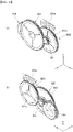
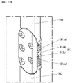
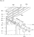
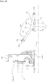
- FIGS. 1 to 34 are diagrams illustrating examples of a display device according to embodiments of the present disclosure.
- suffixes such as “module” and “unit” may be used to refer to elements or components. Use of such suffixes herein is merely intended to facilitate description of the specification, and the suffixes do not have any special meaning or function.
- a display device 100 may include a display unit 20 and a housing 30.
- the housing 30 may have an internal space formed therein. At least a portion of the display unit 20 may be located inside the housing 30. At least a portion of the display unit 20 may be located outside the housing 30.
- the display unit 20 may display an image on the front surface thereof.
- the direction parallel to the longitudinal direction of the housing 30 may be referred to as a first direction DR1.
- the first direction DR1 may be parallel to a +x axis direction or a -x axis direction.
- the +x axis direction may be referred to as a rightward direction.
- the -x axis direction may be referred to as a leftward direction.
- the direction in which the display unit 20 displays an image may be referred to as a +z axis, a forward direction, or the front.
- the direction opposite the direction in which the display unit 20 displays an image may be referred to as a -z axis, a rearward direction, or the rear.
- a third direction DR3 may be parallel to the +z axis direction or the -z axis direction.
- the direction parallel to the height direction of the display device 100 may be referred to as a second direction DR2.
- the second direction DR2 may be parallel to a +y axis direction or a -y axis direction.
- the y axis direction may be referred to as an upward direction.
- the -y axis direction may be referred to as a downward direction.
- the third direction DR3 may be a direction perpendicular to the first direction DR1 and/or the second direction DR2.
- the first direction DR1 and the second direction DR2 may be collectively referred to as a horizontal direction.
- the third direction DR3 may be referred to as a vertical direction.
- a leftward-rightward direction LR may be parallel to the first direction DR1, and an upward-downward direction UD may be parallel to the second direction DR2.
- the display unit 20 may be entirely located inside the housing 30. At least a portion of the display unit 20 may be located outside the housing 30. The degree to which the display unit 20 is exposed to the outside of the housing 30 may be adjusted as necessary.
- a display panel 10 may be flexible.
- the display panel 10 may be an organic light emitting display (OLED).
- OLED organic light emitting display
- the display panel 10 may have a front surface for displaying an image.
- the display panel 10 may have a rear surface facing the front surface.
- the front surface of the display panel 10 may be covered with a light transmissive material.
- the light transmissive material may be glass, resin, or plastic.
- a plate 11 may be coupled to the rear surface of the display panel 10.
- the plate 11 may be coupled, fastened or attached to the rear surface of the display panel 10.
- the plate 11 may include a metal material.
- the plate 11 may be referred to as a module cover 11, a cover 11, a display panel cover 11, or a panel cover 11.
- a resin layer 14 may be coupled to the rear surface of the plate 11.
- the resin layer 14 may cover the plate 11.
- the plate 11 may not be exposed outside due to the resin layer 14.
- the plate 11 may include a plurality of holes 12.
- the plate may include a region in which the holes 12 are formed and regions 11f, 11g, and 11h in which the holes 12 are not formed.
- the regions 11f, 11g, and 11h in which the holes 12 are not formed may surround the region in which the holes 12 are formed.
- the regions 11f, 11g, and 11h in which the holes 12 are not formed may protect the edge of the display panel 10.
- the holes 12 may also be referred to as openings 12.
- the first region 11g in which the holes 12 are not formed, the region in which the holes 12 are formed, and the second region 11g in which the holes 12 are not formed may be sequentially located in the leftward-rightward direction LR of the plate 11.
- the width of the first region 11g in the leftward-rightward direction LR may be a2.
- the width of the region in which the holes 12 are formed in the leftward-rightward direction LR may be a1.
- the width of the second region 11h in the leftward-rightward direction LR may be a3.
- the third region 11f in which the holes 12 are not formed and the region in which the holes 12 are formed may be sequentially located in the upward-downward direction UD
- the height of the third region 11f in the upward-downward direction UD may be b2.
- the height of the region in which the holes 12 are formed in the upward-downward direction UD may be b1.
- the third region 11f in which the holes 12 are not formed may be coupled to a mechanical part.
- the mechanical part may be an upper bar.
- the upper bar may be coupled to a link.
- the holes 12 may be formed by punching the plate 11.
- the holes 12 may be slits 12a and 12b.
- the slits 12a and 12b may extend in the leftward-rightward direction LR of the plate 11.
- the holes 12 may include relatively long slits 12a and relatively short slits 12b.
- Each of the relatively long slits 12a may have a length d8 and a width d9.
- Each of the relatively short slits 12b may have a length d10 and a width d9.
- the slits 12a and 12b may be spaced apart from each other in the leftward-rightward direction LR of the plate 11. Neighboring slits 12a and 12b may be located so as to be spaced apart from each other by a predetermined distance d2.
- the slits 12a and 12b may be spaced apart from each other in the upward-downward direction UD of the plate 11. Neighboring slits 12a and 12b may be located so as to be spaced apart from each other by a predetermined distance d1.
- the plate 11 may be easily wound or unwound. In the case in which the distances d1 and d2 between the slits 12a and 12b are increased, elasticity of the plate 11 may be increased.
- the display panel 10 may have a very small thickness.
- the display panel 10 may easily wrinkle due to the small thickness thereof.
- the display panel 10 may be easily broken by external impact due to the small thickness thereof.
- the plate 11 may be fixed to the display panel 10 to increase rigidity of the display panel 10.
- the plate 11 may support the display panel 10, thereby preventing the display panel 10 from wrinkling.
- the plate 11 may be made of a metal material that exhibits high rigidity.
- the plate 11 is preferably made of a material that exhibits high elastic strength. Since the plate 11 has the slits 12a and 12b, the plate 11 may be wound around or unwound from a roller 143. Since the plate 11 has the slits 12a and 12b, permanent deformation of the plate 11 may be prevented even when the plate is wound around or unwound from the roller 143.
- An adhesive layer 13 may be formed at the rear surface of the display panel 10.
- the adhesive layer 13 may fix the display panel 10 to the plate 11.
- the display panel 10, the adhesive layer 13, and the plate 12 may be coupled integrally to each other so as to form a display unit, and may be wound around or unwound from the roller 143.
- the slits 12a and 12b may be disposed in rows and columns. Odd rows r1, r3, r5, r7, r9, r11, r13, r15, r17, r19, r21, r23, and r25 may be constituted by the relatively long slits 12a.
- the slits 12a in the odd rows r1, r3, r5, r7, r9, r11, r13, r15, r17, r19, r21, r23, and r25 may constitute columns t1, t2, t3, t4, t5, t6, t7, and t8.
- Even rows r2, r4, r6, r8, r10, r12, r14, r16, r18, r20, r22, and r24 may be constituted by the relatively short slits 12b and the relatively long slits 12a.
- the slits 12a and 12b in the even rows may constitute columns.
- the slits 12a and 12b in the even rows r2, r4, r6, r8, r10, r12, r14, r16, r18, r20, r22, and r24 may constitute columns s1, s2, s3, s4, s5, s6, s7, s8, and s9.
- the relatively short slits 12b and the relatively long slits 12a may be alternately disposed in the upward-downward direction UD
- the relatively short slits 12b may be disposed at opposite sides of the even rows r2, r4, r6, r8, r10, r12, r14, r16, r18, r20, r22, and r24 in the leftward-rightward direction LR.
- a straight line 11 that links the center c221 of a first slit 12b221 in a 22nd row r22 and the center c222 of a second slit 12b222 in the 22nd row r22 may pass through the centers of the other slits in the 22nd row r22.
- a straight line 12 that links the center c231 of a first slit 12b231 in a 23rd row r23 and the center c232 of a second slit 12b232 in the 23rd row r23 may pass through the centers of the other slits in the 23rd row r23.
- a straight line 13 that links the center c241 of a first slit 12b241 in a 24th row r24 and the center c242 of a second slit 12b242 in the 24th row r24 may pass through the centers of the other slits in the 24th row r24.
- a straight line 14 that links the center c251 of a first slit 12b251 in a 25th row r25 and the center c252 of a second slit 12b252 in the 25th row r25 may pass through the centers of the other slits in the 25th row r25.
- a straight line 15 that links the center c221 of an 11th slit 12b221 in a first column s1 of the even rows r2, r4, r6, r8, r10, r12, r14, r16, r18, r20, r22, and r24 and the center c241 of a 12th slit 12b241 in the first column s1 may pass through the centers of the other slits in the first column s1.
- a straight line 16 that links the center c231 of a 12th slit 12b231 in a first column t1 of the odd rows r1, r3, r5, r7, r9, r11, r13, r15, r17, r19, r21, r23, and r25 and the center c251 of a 13rd slit 12b251 in the first column t1 may pass through the centers of the other slits in the first column t1.
- a straight line 17 that links the center c222 of an 11th slit 12b222 in a second column s2 of the even rows r2, r4, r6, r8, r10, r12, r14, r16, r18, r20, r22, and r24 and the center c242 of a 12th slit 12b242 in the second column s2 may pass through the centers of the other slits in the second column s2.
- a straight line 18 that links the center c232 of a 12th slit 12b232 in a second column t2 of the odd rows r1, r3, r5, r7, r9, r11, r13, r15, r17, r19, r21, r23, and r25 and the center c252 of a 13rd slit 12b252 in the second column t2 may pass through the centers of the other slits in the second column t2.
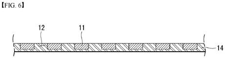
- the first resin layer 14 and the plate 11 may be coupled to each other through a lamination process.
- the plate 11 may be placed on the first resin layer 14.
- the plate 11 and the first resin layer 14 may be heated by a heater.
- a portion of the first resin layer 14 may melt.
- the melted portion of the first resin layer 14 may be adhered to the plate 11.
- a hole 12 in the plate 11 may be filled with the melted portion of the first resin layer 14.
- the plate 11 may be received in the first resin layer 14.
- the plate 11 and the first resin layer 14 may be integrated.
- the front surface of the assembly of the plate 11 and the first resin layer 14 may be flat.
- the adhesive layer 13 may be formed at the rear surface of the display panel 10.
- the adhesive layer 13 may fix the display panel 10 to the plate 11. Since the front surface of the assembly of the plate 11 and the first resin layer 14 is flat, the adhesive layer 13 may fix the display panel 10 to the first resin layer 14.
- the first resin layer 14 may be a material that exhibits high softness.
- the first resin layer 14 may be urethane or rubber.
- the display panel 10, the adhesive layer 13, the plate 11, and the first resin layer 14 may be coupled integrally to each other so as to form a display unit, and may be wound around or unwound from the roller 143.
- the lower end of the display panel 10 may be connected to the roller 143.
- the display panel 10 may be wound around or unwound from the roller 143.
- the front surface of the display panel 10 may be coupled to a plurality of source PCBs 120.
- the plurality of source PCBs 120 may be spaced apart from each other.
- a source chip on film (COF) 123 may connect the display panel 10 and the source PCBs 120.
- the source COF 123 may be located at the front surface of the display panel 10.
- the roller 143 may include a first part 331 and a second part 337.
- the first part 331 and the second part 337 may be fastened by a screw.
- a timing controller board 105 may be mounted in the roller 143.
- the source PCBs 120 may be electrically connected to the timing controller board 105.
- the timing controller board 105 may send digital video data and timing control signals to the source PCBs 120.
- a cable 117 may electrically connect the source PCBs 120 and the timing controller board 105.
- the cable 117 may be a flexible flat cable (FFC).
- the cable 117 may extend through a hole 331a.
- the hole 331a may be formed in a seating portion 379 or the first part 331.
- the cable 117 may be located between the display panel 10 and the second part 337.
- the seating portion 379 may be formed in an outer circumference of the first part 331.
- the seating portion 379 may be formed by stepping a portion of the outer circumference of the first part 331.
- the seating portion 379 may form a space B.
- the cable 117 may electrically connect the timing controller board 105 and the source PCBs 120.
- a base 32 may be flat.
- the base 32 may extend long in the x axis direction.
- a fastening portion 921 may be installed at the upper surface of the base 32.
- the fastening portion 921 may be flat.
- the fastening portion 921 may be fixed to the upper surface of the base 32.
- the fastening portion 921 may be fastened to the base 32 via a fastening member SC.
- a link mount 924 may be formed at the upper surface of the fastening portion 921.
- the link mount 924 may be formed integrally with the fastening portion 921.
- the link mount 924 may include a hole 924a.
- the hole 924a may be formed through the link mount 924 in the z axis direction.
- the link mount 924 may include a wall 924c1 protruding in the +z axis direction.
- the wall 924c1 may form a receiving space 924b1.
- the wall 924c1 may be formed along the circumference of the hole 924a.
- a gear mount 923 may be formed at the upper surface of the fastening portion 921.
- the gear mount 923 may be formed integrally with the fastening portion 921.
- the gear mount 923 may be located at the right side of the link mount 924.
- the gear mount 923 may be formed integrally with the link mount 924.
- the gear mount 923 may include holes 923a1 and 923a2.
- the holes 923a1 and 923a2 may be formed through the gear mount 923 in the z axis direction.
- the first hole 923a1 may be located at the right side of the second hole 923a2.
- the gear mount 923 may include walls 923cl and 923c2 protruding in the +z axis direction.
- the first wall 923cl may form a first receiving space 923b1.
- the first wall 923c1 may be formed along the circumference of the first hole 923a1.
- the second wall 923c2 may form a second receiving space 923b2.
- the second wall 923c2 may be formed along the circumference of the second hole 923a2.
- the first receiving space 923b1 may be located at the right side of the second receiving space 923b2.
- a motor mount 922 may be formed at the upper surface of the fastening portion 921.
- the motor mount 922 may be formed integrally with the fastening portion 921.
- the motor mount 922 may be located at the right side of the gear mount 923.
- the motor mount 922 may be formed integrally with the gear mount 923.
- the motor mount 922 may include a hole 922a.
- the hole 922a may be formed through the motor mount 922 in the z axis direction.
- the motor mount 922 may include a wall 922c1 protruding in the +z axis direction.
- the wall 922c1 may form a receiving space 922.
- the wall 922c1 may be formed along the circumference of the hole 922a.
- the walls 922c1, 923c1, 923c2, and 924c1 may be connected to each other.
- the receiving spaces 922b, 923b1, 923b2, and 924b1 may communicate with each other.
- a hole 921a may be formed in the upper surface of the fastening portion 921.
- the hole 921a may be formed through the fastening portion 921 in the y axis direction.
- the hole 921a may be located at the left side of the link mount 924.
- the hole 921a, the link mount 924, the gear mount 923, and the motor mount 922 may be sequentially located in the x axis direction.
- the motor mount may include a wall protruding in the -z axis direction.
- the wall may be formed along the circumference of the hole.
- the link mount 924 may include a wall 924c2 protruding in the -z axis direction.
- the wall 924c2 may form a receiving space 924b2.
- the wall 924c2 may be formed along the circumference of the hole 924a.
- a motor 800 may be fastened to the rear surface of the motor mount 922.
- the motor 800 may be fixed to the motor mount 922.
- a driving shaft 800d of the motor 800 may be inserted into the hole 922a.
- the driving shaft 800d may be referred to as a rotary shaft 800d.
- the driving shaft 800d of the motor 800 may be coupled to a gear 810.
- the gear 810 may be rotated with the driving shaft 800d when the driving shaft 800d is rotated.
- the gear 810 may be located in the receiving space 922b.
- the wall 922c1 may surround the gear 810.
- a guide plate 925a1 may be fastened to the front surface of the link mount 924 via a fastening member SC.
- the guide plate 925a1 may be fixed to the receiving space 924b1.
- the guide plate 925a1 may include a plurality of guides 925a2.
- the guide plate 925a1 may include a guide recess 925a3 formed between neighboring guides 925a2. Lubricating oil may be applied to the guide plate 925a1.
- a brake 800e may be installed in the motor 800, at the front of the motor 800, or at the rear of the motor 800.
- the driving shaft 800d may extend through the motor 800, and the motor 800 may be installed at the driving shaft 800d.
- the brake 800e may include a disc 800e1 and a caliper 800e2.
- the disc 800e1 may be coupled to the driving shaft 800d.
- the disc 800e1 may be formed integrally with the driving shaft 800d.
- the caliper 800e2 may hold the disc 800e1 to brake the rotation of the disc 800e1.
- the caliper 800e2 may include a pad configured to come into contact with or be separated from the disc 800e1. The pad generates frictional force to brake the rotation of the disc 800e1 when contacting the disc 800e1.
- the motor 800 may be fastened to a wall 922c2 via a fastening member SC.
- a guide plate 925b 1 may be fastened to the rear surface of the link mount 924 via a fastening member SC.
- the guide plate 925b1 may be fixed to the receiving space 924b2.
- the guide plate 925b1 may include a plurality of guides 925b2.
- the guide plate 925b1 may include a guide recess 925b3 formed between neighboring guides 925b2.
- gears 810, 820, 830, and 865 may be spur gears.
- the gear 820 may be installed at the gear mount 923.
- the gear 820 may be received in the receiving space 923b1.
- the wall 923c1 may surround the gear 820.
- a rotary shaft 823 may be inserted into the hole 923a1.
- the rotary shaft 823 may be rotated relative to the gear mount 923.
- the rotary shaft 823 may be fixed to the gear mount 923.
- the gear 820 may be coupled to the rotary shaft 823.
- the gear 820 may be rotated relative to the rotary shaft 823.
- the gear 820 may be fixed to the rotary shaft 823.
- the gear 820 may be formed integrally with the rotary shaft 823.
- the gear 820 may be a double gear.
- the gear 820 may include a primary gear 821 and a secondary gear 822.
- the rotary shaft 823 of the primary gear 821 and the rotary shaft 823 of the secondary gear 822 may be the same.
- the primary gear 821 and the secondary gear 822 may be integrally formed.
- the diameter of the secondary gear 822 may be greater than the diameter of the primary gear 821.
- the number of teeth of the secondary gear 822 may be greater than the number of teeth of the primary gear 821.
- the secondary gear 822 may be engaged with the gear 810.
- the secondary gear 822 may be received in the receiving space 923b1.
- the wall 923c1 may surround the secondary gear 822.
- the gear 830 may be installed at the gear mount 923.
- the gear 830 may be received in the receiving space 923b2.
- the wall 923c2 may surround the gear 830.
- a rotary shaft 833 may be inserted into the hole 923a2.
- the rotary shaft 833 may be rotated relative to the gear mount 923.
- the rotary shaft 833 may be fixed to the gear mount 923.
- the gear 830 may be coupled to the rotary shaft 833.
- the gear 830 may be rotated relative to the rotary shaft 833.
- the gear 830 may be fixed to the rotary shaft 833.
- the gear 830 may be formed integrally with the rotary shaft 833.
- the gear 830 may be a double gear.
- the gear 830 may include a primary gear 831 (see FIG. 15 ) and a secondary gear 832.
- the rotary shaft 833 of the primary gear 831 and the rotary shaft 833 of the secondary gear 832 may be the same.
- the primary gear 831 and the secondary gear 832 may be integrally formed.
- the diameter of the secondary gear 832 may be greater than the diameter of the primary gear 831.
- the number of teeth of the secondary gear 832 may be greater than the number of teeth of the primary gear 831.
- the secondary gear 832 may be engaged with the gear 820.
- the secondary gear 832 may be engaged with the primary gear 821.
- the primary gear 831 may be received in the receiving space 923b2.
- the wall 923c2 may surround the primary gear 831.
- torque output from the motor 800 may be transmitted to the fourth gear 965 via the first gear 810, the second gear 820, and the third gear 830.
- a link 860 fastened to the fourth gear 965 may be rotated or pivoted.
- the first gear 810 may be engaged with the secondary gear 822 of the second gear 820.
- the number of teeth of the secondary gear 822 may be greater than the number of teeth of the first gear 810.
- the number of teeth of the first gear 810 may be 14, and the number of teeth of the secondary gear 822 may be 60.
- the gear reduction ratio (the gear ratio or the reduction ratio) of the secondary gear 822 to the first gear 810 may be 4.29.
- the gear reduction ratio (the gear ratio or the reduction ratio) of the secondary gear 822 to the first gear 810 may be 3 to 6.
- the primary gear 821 of the second gear 820 may be engaged with the secondary gear 832 to the third gear 830.
- the number of teeth of the secondary gear 832 may be greater than the number of teeth of the primary gear 821.
- the number of teeth of the primary gear 821 may be 15, and the number of teeth of the secondary gear 832 may be 70.
- the gear reduction ratio of the secondary gear 832 to the primary gear 821 may be 4.67.
- the gear reduction ratio of the secondary gear 832 to the primary gear 821 may be 3 to 6.
- the primary gear 831 of the third gear 830 may be engaged with the fourth gear 865.
- the number of teeth of the fourth gear 865 may be greater than the number of teeth of the primary gear 831.
- the number of teeth of the fourth gear 865 may be 26, and the number of teeth of the primary gear 831 may be 12.
- the gear reduction ratio of the fourth gear 865 to the primary gear 831 may be 2.17.
- the gear reduction ratio of the fourth gear 865 to the primary gear 831 may be 1.5 to 3.
- the gear reduction ratio of the fourth gear 865 to the first gear 810 may be the product of the gear reduction ratio of the second gear 820 to the first gear 810, the gear reduction ratio of the third gear 830 to the second gear 820, and the gear reduction ratio of the fourth gear 865 to the third gear 830.
- the first gear 810 to the fourth gear 865 may amplify torque of the motor 800, thereby rotating or pivoting the link 860.
- the diameter of the first gear 810 may be 11.5 mm
- the diameter of the primary gear 821 of the second gear 820 may be 11.5 mm
- the diameter of the secondary gear 822 of the second gear 820 may be 57.5 mm
- the diameter of the primary gear 831 of the third gear 830 may be 14.25 mm
- the diameter of the secondary gear 832 of the third gear 830 may be 67.5 mm
- the diameter of the fourth gear 865 may be 39 mm.
- the diameter of the first gear 810 may be 14 mm
- the diameter of the primary gear 821 of the second gear 820 may be 14 mm
- the diameter of the secondary gear 822 of the second gear 820 may be 60 mm
- the diameter of the primary gear 831 of the third gear 830 may be 18 mm
- the diameter of the secondary gear 832 of the third gear 830 may be 70 mm
- the diameter of the fourth gear 865 may be 42 mm.
- the diameter of the first gear 810 may be 16 mm
- the diameter of the primary gear 821 of the second gear 820 may be 16 mm
- the diameter of the secondary gear 822 of the second gear 820 may be 62 mm
- the diameter of the primary gear 831 of the third gear 830 may be 21 mm
- the diameter of the secondary gear 832 of the third gear 830 may be 72 mm
- the diameter of the fourth gear 865 may be 45 mm.
- a first gear 810a may be a worm gear.
- a secondary gear 822a of a second gear 820a may be a worm wheel gear.
- the gear reduction ratio of to the secondary gear 822a to the first gear 810a may be greatly increased.
- the gear reduction ratio may mean the number of revolutions of the first gear 810a while the secondary gear 822a makes one revolution.
- the motor 800 may be installed in a direction parallel to the x axis.
- a first gear 810b and a secondary gear 822b of a second gear 820b may be bevel gears.
- the motor 800 may be installed in a direction parallel to the x axis.
- a lower link 912 may be fastened to the front surface of the link 860 via a fastening member SC2.
- the lower link 912 may be fixed to the front surface of the link 860.
- the lower link 912 and the link 860 may be integrally formed.
- a cover 926 may be fastened to the front surface of a mount 920 via a fastening member SC.
- the cover 926 may cover the gears 810, 820, 830, and 885.
- a right assembly RA may include a mount 920, a cover 926, a motor 800, gears 810, 820, 830, and 885, or a link 912RL.
- the link 912RL may include a lower link 912, an upper link 911, or a joint 913.
- the link 912RL may be referred to as a foldable link 912RL, a lift 912RL, a lift assembly 912RL, a foldable lift 912RL, or a foldable lift assembly 912RL.
- a left assembly LA may include the same components as the right assembly RA
- the left assembly LA and the right assembly RA may be symmetrical.
- the left assembly LA may include a mount 920L, a cover 926L, a motor 800L, gears, or a link 912LL.
- the link 912LL may include a lower link 912L, an upper link 911L, or a joint 913L.
- the link 912LL may be referred to as a foldable link 912LL, a lift 912LL, a lift assembly 912LL, a foldable lift 912LL, or a foldable lift assembly 912LL.
- the links 912RL and 912LL may be folded or unfolded.
- a first base 31 may be flat.
- the first base 31 may face a second base 32.
- the first base 31 may be located under the second base 32.
- a support 35 may be located between the first base 31 and the second base 32.
- the support 35 may be fastened to the first base 31 via a fastening member.
- the support 35 may be fastened to the second base 32 via a fastening member.
- the roller 143 may be installed at the first base 31.
- the roller 143 may be located between the first base 31 and the second base 32.
- a portion of the display unit 20 may be wound around the roller 143, and a portion of the display unit 20 may be unwound from the roller 143.
- the portion of the display unit 20 unwound from the roller 143 may extend upwards.
- a gear 912a may be formed at the upper end of the lower link 912.
- the gear 912a may be coupled to the upper end of the lower link 912.
- the gear 912a may be fixed to the upper end of the lower link 912.
- the gear 912a may be formed integrally with the lower link 912.
- a gear 911a may be formed at the lower end of the upper link 911.
- the gear 911a may be coupled to the lower end of the upper link 911.
- the gear 911a may be fixed to the lower end of the upper link 911.
- the gear 911a may be formed integrally with the upper link 911.
- the gears 912a and 911a may be engaged with each other.
- the gears 911a and 912a may be rotated relative to a first part 913a.
- the lower link 912 may be referred to as an arm 912.
- a second part 913b may be fastened to the first part 913a via a fastening member SC.
- the second part 913b may be fixed to the first part 913a.
- the gears 911a and 912a may be rotated relative to the first part 913a or the second part 913b.
- the upper part of the display unit 20 may be bent rearwards.
- the upper part of the display unit 20 may be the portion of the plate 11 that is not coupled to the display panel 10.
- the upper part of the plate 11 bent rearwards may be referred to as a bending portion 11a or a first part 11a.
- a portion connected to the bending portion 11a may be referred to as a second part 11i .
- a top case 950 may be located at the upper side of the bending portion 11a.
- a gasket 954 may be located between the top case 950 and the bending portion 11a.
- a lower bar 953 may be located at the lower side of the bending portion 11a.
- the lower bar 953 may be referred to as a bar 953.
- the lower bar 953 may include a horizontal portion 953a and a vertical portion 953b.
- the gasket 954 may include a hole 954a.
- the bending portion 11a may include a hole 11b.
- the horizontal portion 953a may include a hole 953e.
- the hole 954a of the gasket 954, the hole 11b of the bending portion 11a, and the hole 953e of the horizontal portion 953a may face each other.
- a fastening member SC may be fastened to the top case 950 through the hole 953e of the horizontal portion 953a, the hole 11b of the bending portion 11a, and the hole 954a of the gasket 954.
- the vertical portion 953b may be located so as to be perpendicular to the horizontal portion 953a.
- the vertical portion 953b may support the plate 11.
- the vertical portion 953b may face a link bracket 951.
- the vertical portion 953b may include a first coupling portion 953c and a second coupling portion 953d protruding rearwards.
- the second coupling portion 953d may be inserted into a bearing 955.
- the bearing 955 may be referred to as a ring bearing 955.
- the bearing 955 may be inserted into a hole 911a of a first arm 911.
- the link bracket 951 may include a first hole 951a and a second hole 951b.
- a fastening member SC may extend through the first hole 951a, and may be fastened to the first coupling portion 953c.
- a fastening member SC may extend through the second hole 951b, and may be fastened to the second coupling portion 953d.
- the link bracket 951 may be fixed to the lower bar 953 via the first hole 951a, the first coupling portion 953c, and the fastening member SC.
- the first arm 911 may be pivotably connected to the lower bar 953 via the second coupling portion 953d, the bearing 955, the second hole 951b, and the fastening member SC. In this structure, wrinkles W or rumples W of the display unit 20 may be reduced.
- the upper link 911 may be rotated or pivoted relative to the second coupling portion 953d or the link bracket 951.
- a rear wall 950d may extend to the lower side of a first part 950a.
- the rear wall 950d may be referred to as a second part 950d.
- the rear wall 950d may cover the bending portion 11a, the gasket 954, or the horizontal portion 953a.
- a first front wall 950b may extend to the lower side of the first part 950a.
- the first front wall 950b may be referred to as a third part 950b.
- the first front wall 950b may cover the upper part of the plate 11 or the second part 11i.
- a second front wall 950c may extend to the lower side of the first front wall 950b.
- the second front wall 950c may be referred to as a fourth part 950c.
- the second front wall 950c may cover the upper part of the display panel 10.
- the second front wall 950c may cover wrinkles W or rumples W that may be generated at the upper part of the display panel 10.
- the thickness W5 of the first front wall 950b may be greater than the thickness W6 of the second front wall 950c.
- the thickness W5 of the first front wall 950b may be substantially equal to the sum of the thickness W6 of the second front wall 950c and the thickness of the display panel 10.
- the first arm 911 may include a first part 911b that faces the vertical portion 953b and a second part 911c that faces the plate 11.
- the thickness W9 of the second part 911c may be substantially equal to the sum of the thickness W7 of the vertical portion 953b and the thickness W8 of the first part 911b.
- the second part 911c is in contact with or adjacent to the display unit 20, whereby the display unit 20 may be stably supported.
- the roller 143 may be installed at a mount 36.
- the mount 36 may be installed at the base 31.
- the mount 36 may be installed at one end and the other end of the roller 143 in the longitudinal direction (x axis direction).
- the roller 143 may be installed between mounts 36.
- the roller 143 may be rotated relative to the mount 36.
- a hub 278 may be installed at the mount 36.
- the mount 36 may be located between the roller 143 and the hub 278.
- the hub 278 may be coupled or fixed to one end of the roller 143.
- the hub 278 may be formed integrally with the roller 143. As the roller 143 is rotated, the hub 278 may be rotated.
- the rotational speed of the roller 143 may be equal to the rotational speed of the hub 278.
- a rotary shaft 315 may be installed at the mount 36.
- the rotary shaft 315 may be rotated relative to the mount 36.
- a spring 314 may be wound around the rotary shaft 315.
- the spring 314 may be a constant force spring.
- the spring 314 may be wound around the rotary shaft 315 a plurality of times.
- One end of the spring 314 may be fixed to the rotary shaft 315.
- the other end of the spring 314 may be fixed to the hub 278.
- the spring 314 may extend towards the hub 278, and may be wound around or unwound from the circumference of the hub 278.
- the spring 314 may be wound around or unwound from the rotary shaft 315, and may provide restoring force to the hub 278.
- the restoring force may be formed by which the spring 314 is wound around the rotary shaft 315.
- a guide 316 may guide winding or unwinding of the spring 314 around or from the rotary shaft 315.
- the rotary shaft 315 may be located lower than the hub 278 by a distance CSD in the y axis direction. In the case in which the rotary shaft 315 is located lower than the hub 278, greater force may be transmitted to the hub 278 than in the case in which the rotary shaft 315 is located level with or higher than the hub 278. Due to restoring force that the spring 314 provides to the hub 278, the display unit 20 may be wound around the roller 143.
- torque applied thereto may be increased as the number of revolutions is increased, as shown by a dotted line.
- torque applied thereto may be uniform when the number of revolutions exceeds a predetermined value, as shown by a solid line. Variation in torque necessary to wind the display unit 20 around the roller 143 may not be great, compared to the number of times that the display unit 20 is wound around the roller 143. In the case in which the constant force spring is applied to acquire uniform torque, therefore, it is possible to stably drive the roller 143.
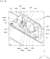
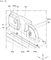
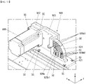
- a fulcrum 710 may include a lever base 711, a first support 712, and a second support 713.
- the lever base 711 may be mounted on the base 32 (see FIG. 12 ).
- the lever base 711 may have a first support mount 710a and a second support mount 710b.
- the first support mount 710a may protrude toward the upper side of the lever base 711, and may have an axial hole.
- the second support mount 710b may protrude toward the upper side of the lever base 711, and may have an axial hole spaced apart from the first support mount 710a in the state of being parallel thereto.
- the first support 712 may be inserted into the first support mount 710a.
- the first support 712 may be referred to as a first support shaft 712.
- the second support 713 may be inserted into the second support mount 710b.
- the second support 713 may be referred to as a second support shaft 713.
- the height of the first support mount 710a may be greater than the height of the second support mount 710b. That is, this means that the position of the first support 712 may be higher than the position of the second support 713 with respect to the lever base 711.
- a lever 720 may include a center 721, a first bar 722, a second bar 725, a first fork 723 and 724, and a second fork 726 and 727.
- the lever 720 may be generally bent in the form of V.
- the center 721 may be pivotably coupled to the first support 712.
- the first bar 722 may extend long from one side of the center 721, and the second bar 725 may extend long from the other side of the center 721.
- the first bar 722 may be opposite the second bar 725 with respect to the center 721.
- the length of the first bar 722 may be greater than the length of the second bar 725.
- the first fork 723 and 724 may be formed so as to extend long from the first bar 722 in a direction far away from the center 721.
- the first fork 723 and 724 may have two blades 723 and 724.
- the second fork 726 and 727 may be formed so as to extend long from the second bar 725 in a direction far away from the center 721.
- the second fork 726 and 727 may have two blades 726 and 727.
- the length of the blades 726 and 727 of the second fork may be greater than the length of the blades 723 and 724 of the first fork.
- the distance between the blades 726 and 727 of the second fork may be less than the distance between the blades 723 and 724 of the first fork.
- a roller shaft 730 may be inserted into the distal ends of the blades 723 and 724 of the first fork.
- a roller 760 may be fitted on the roller shaft 730.
- the roller 760 may include a urethane material.
- a holder shaft 740 may be inserted into the distal ends of the blades 726 and 727 of the second fork.
- One end of a spring 750 may be caught by the second support 713, and the other end of the spring 750 may be caught by the holder shaft 740.
- the spring 750 may be an extension spring.
- the height of the top case 950 in the y axis direction may be the maximum.
- the angle E formed by the lower links 912 and 912L and the upper links 911 and 911L may be the maximum.
- the angle E may be 180 degrees.
- the display unit 20 may be in the state of being maximally unwound from the roller 143.
- the roller 760 of the lever 700 may not contact the links 860 and 860L.
- the motors 800 and 800L may rotate or pivot the lower links 912 and 912L.
- the angle D formed by the lower links 912 and 912L and the upper links 911 and 911L may increase.
- the angle formed by the lower links 912 and 912L and the base 32L may increase.
- the top case 950 may move in the +y axis direction.
- the display unit may be unwound from the roller.
- the angle D formed by the lower links 912 and 912L and the upper links 911 and 911L may decrease.
- the angle D formed by the lower links 912 and 912L and the base 32L may increase.
- the top case 950 may move in the -y axis direction.
- the display unit may be wound around the roller.
- the distance between the joints 913 and 913L may increase.
- the distance between the joints 913 and 913L may decrease.
- the height of the top case 950 in the y axis direction may be the minimum.
- the angle G formed by the lower links 912 and 912L and the upper links 911 and 911L may be the minimum.
- the display unit 20 may be in the state of being maximally wound around the roller 143.
- the roller 760 of the lever 700 may contact the links 860 and 860L.
- the links 860 and 860L may push the roller 760 of the lever 700, the lever 700 may be pivoted about the first support 712.
- the height of the roller 760 of the lever 700 may decrease, and the height of the holder shaft 740 of the lever 720 may increase.
- a change may be made from the state in which the height of the roller 760 of the lever 700 is greater than the height of the holder shaft 740 of the lever 720 to the state in which the height of the roller 760 of the lever 700 is less than the height of the holder shaft 740 of the lever 720.
- the length of the spring 750 may increase, and the lever 720 may provide the links 860 and 860L with force by which the height of the roller 760 of the lever 700 is restored to the state in which the height of the roller 760 of the lever 700 is greater than the height of the holder shaft 740 of the lever 720.
- the lever 720 may provide erecting force to the links 860 and 860L at the time of initial driving (erecting operation) of the links 860 and 860L, and may provide damping force to the links 860 and 860L at the time of final driving (folding operation) of the links 860 and 860L.
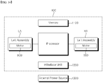
- the display device 100 may include an interface unit 1200 connected to an external device.
- the interface unit 1200 may be connected to an external power source 1300, and may receive power from the external power source 1300.
- a processor 1000 may distribute power to respective components.
- the processor 1000 may be referred to as a control unit 1000 or a controller 1000.
- a memory 1100 may store various data necessary to operate the display device 100, such as programs for processing or control of the processor 1000.
- the memory 1100 may store various application programs or applications driven in the display device 100.
- the processor 1000 may control the operation of the left assembly LA and the right assembly RA Driving of the left assembly LA and the driving of the right assembly RA must be performed in a symmetrical fashion such that the display unit 20 is smoothly wound around or unwound from the roller 143.
- the processor 1000 may simultaneously control the motors 800 and 800L.
- the processor 1000 may control the rotational amounts, rotational speeds, or rotational directions of the driving shafts 800d and 800Ld of the motors 800 and 800L.
- the processor 1000 may perform control such that the rotational directions of the driving shafts 800d and 800Ld of the motors 800 and 800L are opposite each other.
- the processor 1000 may perform control such that the rotational speeds of the driving shafts 800d and 800Ld of the motors 800 and 800L are the same.
- the processor 1000 may perform control such that the rotational amounts of the driving shafts 800d and 800Ld of the motors 800 and 800L are the same.
- the rotational amounts or pivoting amounts of the links 911 and 911L may be the same.
- the links 911 and 911L may be operated in a symmetrical fashion.
- the top case 950 may move upwards and downwards in the y axis direction while remaining horizontal.
- the processor 1000 may sense the rotational amount, rotational speed, or rotational direction of the motor 800L of the left assembly LA through a position sensor 800Lb.
- the position sensor 800Lb may include at least one of a PCB 870 or a sensor 890.
- the rotational amount may mean angular displacement.
- the rotational speed may mean angular velocity.
- the processor 1000 may sense the rotational amount, rotational speed, or rotational direction of the motor 800 of the right assembly RA through a position sensor 800b.
- the position sensor 800b may include at least one of a PCB 870 or a sensor 890.
- the motors 800 and 800L may have brakes 800e and 800Le for braking the driving shafts 800d and 800Ld.
- the processor 1000 may control operation of the brakes 800e and 800Le in order to reduce the rotational speeds of the motors 800 and 800L or to stop driving of the motors 800 and 800L.
- the processor 1000 may decrease the rotational speed of the motor having the larger rotational amount, or may stop driving of the motor having the larger rotational amount. Alternatively, in the case in which the rotational amount of one of the motors 800 and 800L is larger, the processor 1000 may increase the rotational speed of the motor having the smaller rotational amount.
- the processor 1000 may decrease the rotational speed of the motor having the higher rotational speed, or may stop driving of the motor having the higher rotational speed. Alternatively, in the case in which the rotational speed of one of the motors 800 and 800L is higher, the processor 1000 may increase the rotational speed of the motor having the lower rotational speed.
- the motors 800 and 800L may have encoders 800La and 800a for sensing rotational amounts, rotational speeds, or rotational directions of the driving shafts 800d and 800Ld.
- the processor 100 may receive information about the rotational amounts, rotational speeds, or rotational directions of the driving shafts 800d and 800Ld of the motors 800 and 800L through the encoders 800La and 800a.
- the motors 800 and 800L may have brakes 800e and 800Le for braking rotation of the driving shafts 800d and 800Ld.
- the processor may control operation of the brakes 800e and 800Le in order to reduce the rotational speeds of the motors 800 and 800L or to stop driving of the motors 800 and 800L.
- the processor 1000 may decrease the rotational speed of the motor having the larger rotational amount, or may stop driving of the motor having the larger rotational amount. Alternatively, in the case in which the rotational amount of one of the motors 800 and 800L is larger, the processor 1000 may increase the rotational speed of the motor having the smaller rotational amount.
- the processor 1000 may decrease the rotational speed of the motor having the higher rotational speed, or may stop driving of the motor having the higher rotational speed. Alternatively, in the case in which the rotational speed of one of the motors 800 and 800L is higher, the processor 1000 may increase the rotational speed of the motor having the lower rotational speed.
- each of the motors 800 and 800L may be a step motor, a stepper motor, or a stepping motor.
- the processor 1000 may simultaneously control the motors 800 and 800L.
- the processor 1000 may control the rotational amounts, rotational speeds, or rotational directions of the driving shafts 800d and 800Ld of the motors 800 and 800L.
- the rotational amounts of the driving shafts 800d and 800Ld of the motors 800 and 800L may mean the number of steps that the driving shafts 800d and 800Ld are rotated.
- the rotational speeds of the driving shafts 800d and 800Ld of the motors 800 and 800L may mean the number of steps that the driving shafts 800d and 800Ld are rotated per unit time.
- the motors 800 and 800L may have brakes 800e and 800Le for braking rotation of the driving shafts 800d and 800Ld.
- the processor 1000 may control operation of the brakes 800e and 800Le in order to reduce the rotational speeds of the motors 800 and 800L or to stop driving of the motors 800 and 800L.
- the processor 100 may receive information about the rotational amounts, rotational speeds, or rotational directions of the driving shafts 800d and 800Ld of the motors 800 and 800L from the motors 800 and 800L.
- the processor 1000 may decrease the rotational speed of the motor having the larger rotational amount, or may stop driving of the motor having the larger rotational amount. Alternatively, in the case in which the rotational amount of one of the motors 800 and 800L is larger, the processor 1000 may increase the rotational speed of the motor having the smaller rotational amount.
- the processor 1000 may decrease the rotational speed of the motor having the higher rotational speed, or may stop driving of the motor having the higher rotational speed. Alternatively, in the case in which the rotational speed of one of the motors 800 and 800L is higher, the processor 1000 may increase the rotational speed of the motor having the lower rotational speed.
- a configuration "A” described in one embodiment of the disclosure and the drawings and a configuration "B” described in another embodiment of the disclosure and the drawings may be combined with each other. Namely, although the combination between the configurations is not directly described, the combination is possible except in the case where it is described that the combination is impossible.
Landscapes
- Engineering & Computer Science (AREA)
- Theoretical Computer Science (AREA)
- Computer Hardware Design (AREA)
- General Engineering & Computer Science (AREA)
- Human Computer Interaction (AREA)
- Physics & Mathematics (AREA)
- General Physics & Mathematics (AREA)
- Devices For Indicating Variable Information By Combining Individual Elements (AREA)
Abstract
Description
- The present disclosure relates to a display device.
- As the information society has developed, the demand for display devices is increasing in various forms, and accordingly, in recent years, various display devices such as a liquid crystal display (LCD), plasma display panel (PDP), electroluminescent display (ELD), vacuum fluorescent display (VFD), and the like have been studied and used.
- Thereamong, a display device using an organic light emitting diode (OLED) has excellent luminance and viewing angle characteristics in comparison with a liquid crystal display device and does not require a backlight unit, thereby being implemented in an ultrathin type.
- In addition, a flexible display panel can be bent or wound around a roller. The flexible display panel may be used to implement a display device that unfolds on a roller or winds around the roller. There is a necessity for many studies on a structure for winding a flexible display panel around a roller or unwinding the flexible display panel from the roller.
- It is an object of the present disclosure to solve the above and other problems.
- It is another object of the present disclosure to provide a display device capable of reducing load at the time of initial driving for unwinding a display panel from a roller.
- It is another object of the present disclosure to provide a display device capable of reducing initial driving force at the time of erecting a link.
- It is a further object of the present disclosure to provide a display device capable of reducing impact at the time of seating the link.
- In accordance with an aspect of the present disclosure, the above and other objects can be accomplished by the provision of a display device including a housing extending long, a roller installed in the housing, a display unit configured to be wound around or unwound from the roller, a foldable link having one side pivotably connected to the housing and the other side pivotably connected to the upper part of the display unit, a motor installed in the housing, the motor being configured to pivot the foldable link, a fulcrum installed in the housing in the state of being adjacent to the one side of the foldable link, a lever extending in the longitudinal direction of the housing, the lever being pivotably mounted on the fulcrum, the foldable link coming into contact with one side of the lever in the longitudinal direction thereof as folded in the housing, and an elastic member configured to connect the other side of the lever in the longitudinal direction thereof and the fulcrum to each other.
- In accordance with another aspect of the present disclosure, the foldable link may include a lower link having one side pivotably connected to the housing and an upper link having one side pivotably connected to the lower link and the other side pivotably connected to the upper part of the display unit, and the lever may come into contact with the lower link as the foldable link is folded.
- In accordance with another aspect of the present disclosure, the fulcrum may include a lever base fixed to the housing, a first support formed at the upper side of the lever base, a first shaft being inserted into the first support, and a second support formed at the upper side of the lever base so as to be spaced apart from the first support, a second shaft being inserted into the second support, the second shaft being parallel to the first shaft, the lever may be pivotably mounted at the first shaft of the first support, and the elastic member may connect the second shaft of the second support and the other side of the lever to each other.
- In accordance with another aspect of the present disclosure, the lever may include a center coupled to the first shaft of the first support, a first bar extending from the center toward one side of the lower link, a second bar extending from the center so as to be opposite the first bar, a first fork formed at the distal end of the first bar, a second fork formed at the distal end of the second bar, a roller shaft extending through blades of the first fork, and a roller fitted on the roller shaft so as to be rotatable on the roller shaft.
- In accordance with another aspect of the present disclosure, the roller may include a urethane material.
- In accordance with another aspect of the present disclosure, the second bar may be bent relative to the first bar in the upward direction, and the elastic member may be an extension spring.
- In accordance with another aspect of the present disclosure, the elastic member may be lengthened when the foldable link is folded and may be shortened when the foldable link is unfolded.
- In accordance with another aspect of the present disclosure, the distance between the blades of the first fork may be greater than the distance between blades of the second fork.
- In accordance with another aspect of the present disclosure, the motor may include a rotary encoder configured to sense angular displacement of a driving shaft of the motor, and the display device may further include a controller configured to acquire information about the angular displacement of the driving shaft from the rotary encoder and to control the motor.
- In accordance with a further aspect of the present disclosure, the display device may further include a first gear fixed to the driving shaft of the motor and a second gear fixed to the lower link, the second gear having a rotary shaft aligned with a pivot shaft of the lower link, the second gear being engaged with the first gear.
- The display device according to the present disclosure has the following effects.
- According to at least one of the embodiments of the present disclosure, it is possible to reduce load at the time of initial driving for unwinding a display panel from a roller.
- In addition, according to at least one of the embodiments of the present disclosure, it is possible to reduce initial driving force at the time of erecting a link.
- In addition, according to at least one of the embodiments of the present disclosure, it is possible to reduce impact at the time of seating the link.
- Further scope of applicability of the present disclosure will become apparent from the detailed description given hereinafter. However, it should be understood that the detailed description and specific examples, while indicating preferred embodiments of the present disclosure, are given by illustration only, since various changes and modifications within the spirit and scope of the present disclosure will become apparent to those skilled in the art from this detailed description.
-
FIGS. 1 to 34 are diagrams illustrating examples of a display device according to embodiments of the present disclosure. - Description will now be given in detail according to exemplary embodiments disclosed herein, with reference to the accompanying drawings. For the sake of brief description with reference to the drawings, the same or equivalent components may be denoted by the same reference numbers, and description thereof will not be repeated.
- In general, suffixes such as "module" and "unit" may be used to refer to elements or components. Use of such suffixes herein is merely intended to facilitate description of the specification, and the suffixes do not have any special meaning or function.
- In the present disclosure, that which is well known to one of ordinary skill in the relevant art has generally been omitted for the sake of brevity. The accompanying drawings are used to assist in easy understanding of various technical features and it should be understood that the embodiments presented herein are not limited by the accompanying drawings. As such, the present disclosure should be construed to extend to any alterations, equivalents and substitutes in addition to those which are particularly set out in the accompanying drawings.
- It will be understood that although the terms first, second, etc. may be used herein to describe various elements, these elements should not be limited by these terms. These terms are only used to distinguish one element from another.
- It will be understood that when an element is referred to as being "connected with" another element, there may be intervening elements present. In contrast, it will be understood that when an element is referred to as being "directly connected with" another element, there are no intervening elements present.
- A singular representation may include a plural representation unless context clearly indicates otherwise.
- Referring to
FIG. 1 , adisplay device 100 may include adisplay unit 20 and ahousing 30. Thehousing 30 may have an internal space formed therein. At least a portion of thedisplay unit 20 may be located inside thehousing 30. At least a portion of thedisplay unit 20 may be located outside thehousing 30. Thedisplay unit 20 may display an image on the front surface thereof. - The direction parallel to the longitudinal direction of the
housing 30 may be referred to as a first direction DR1. The first direction DR1 may be parallel to a +x axis direction or a -x axis direction. The +x axis direction may be referred to as a rightward direction. The -x axis direction may be referred to as a leftward direction. The direction in which thedisplay unit 20 displays an image may be referred to as a +z axis, a forward direction, or the front. The direction opposite the direction in which thedisplay unit 20 displays an image may be referred to as a -z axis, a rearward direction, or the rear. A third direction DR3 may be parallel to the +z axis direction or the -z axis direction. The direction parallel to the height direction of thedisplay device 100 may be referred to as a second direction DR2. The second direction DR2 may be parallel to a +y axis direction or a -y axis direction. The y axis direction may be referred to as an upward direction. The -y axis direction may be referred to as a downward direction. The third direction DR3 may be a direction perpendicular to the first direction DR1 and/or the second direction DR2. - The first direction DR1 and the second direction DR2 may be collectively referred to as a horizontal direction. In addition, the third direction DR3 may be referred to as a vertical direction.
- A leftward-rightward direction LR may be parallel to the first direction DR1, and an upward-downward direction UD may be parallel to the second direction DR2.
- Referring to
FIG. 2 , thedisplay unit 20 may be entirely located inside thehousing 30. At least a portion of thedisplay unit 20 may be located outside thehousing 30. The degree to which thedisplay unit 20 is exposed to the outside of thehousing 30 may be adjusted as necessary. - Referring to
FIG. 3 , adisplay panel 10 may be flexible. For example, thedisplay panel 10 may be an organic light emitting display (OLED). - The
display panel 10 may have a front surface for displaying an image. Thedisplay panel 10 may have a rear surface facing the front surface. The front surface of thedisplay panel 10 may be covered with a light transmissive material. For example, the light transmissive material may be glass, resin, or plastic. - A
plate 11 may be coupled to the rear surface of thedisplay panel 10. Theplate 11 may be coupled, fastened or attached to the rear surface of thedisplay panel 10. Theplate 11 may include a metal material. Theplate 11 may be referred to as amodule cover 11, acover 11, adisplay panel cover 11, or apanel cover 11. - A
resin layer 14 may be coupled to the rear surface of theplate 11. Theresin layer 14 may cover theplate 11. Theplate 11 may not be exposed outside due to theresin layer 14. - Referring to
FIG. 4 , theplate 11 may include a plurality ofholes 12. The plate may include a region in which theholes 12 are formed andregions holes 12 are not formed. Theregions holes 12 are not formed may surround the region in which theholes 12 are formed. Theregions holes 12 are not formed may protect the edge of thedisplay panel 10. Theholes 12 may also be referred to asopenings 12. - The
first region 11g in which theholes 12 are not formed, the region in which theholes 12 are formed, and thesecond region 11g in which theholes 12 are not formed may be sequentially located in the leftward-rightward direction LR of theplate 11. The width of thefirst region 11g in the leftward-rightward direction LR may be a2. The width of the region in which theholes 12 are formed in the leftward-rightward direction LR may be a1. The width of thesecond region 11h in the leftward-rightward direction LR may be a3. - The third region 11f in which the
holes 12 are not formed and the region in which theholes 12 are formed may be sequentially located in the upward-downward direction UD The height of the third region 11f in the upward-downward direction UD may be b2. The height of the region in which theholes 12 are formed in the upward-downward direction UD may be b1. - The third region 11f in which the
holes 12 are not formed may be coupled to a mechanical part. For example, the mechanical part may be an upper bar. The upper bar may be coupled to a link. - The
holes 12 formed through theplate 11. Theholes 12 may be formed by punching theplate 11. Theholes 12 may beslits 12a and 12b. Theslits 12a and 12b may extend in the leftward-rightward direction LR of theplate 11. Theholes 12 may include relatively long slits 12a and relativelyshort slits 12b. - Each of the relatively long slits 12a may have a length d8 and a width d9. Each of the relatively
short slits 12b may have a length d10 and a width d9. - The
slits 12a and 12b may be spaced apart from each other in the leftward-rightward direction LR of theplate 11. Neighboringslits 12a and 12b may be located so as to be spaced apart from each other by a predetermined distance d2. - The
slits 12a and 12b may be spaced apart from each other in the upward-downward direction UD of theplate 11. Neighboringslits 12a and 12b may be located so as to be spaced apart from each other by a predetermined distance d1. - In the case in which the distances d1 and d2 between the
slits 12a and 12b are decreased, theplate 11 may be easily wound or unwound. In the case in which the distances d1 and d2 between theslits 12a and 12b are increased, elasticity of theplate 11 may be increased. - The
display panel 10 may have a very small thickness. Thedisplay panel 10 may easily wrinkle due to the small thickness thereof. Thedisplay panel 10 may be easily broken by external impact due to the small thickness thereof. - The
plate 11 may be fixed to thedisplay panel 10 to increase rigidity of thedisplay panel 10. Theplate 11 may support thedisplay panel 10, thereby preventing thedisplay panel 10 from wrinkling. - The
plate 11 may be made of a metal material that exhibits high rigidity. Theplate 11 is preferably made of a material that exhibits high elastic strength. Since theplate 11 has theslits 12a and 12b, theplate 11 may be wound around or unwound from aroller 143. Since theplate 11 has theslits 12a and 12b, permanent deformation of theplate 11 may be prevented even when the plate is wound around or unwound from theroller 143. - An
adhesive layer 13 may be formed at the rear surface of thedisplay panel 10. Theadhesive layer 13 may fix thedisplay panel 10 to theplate 11. Thedisplay panel 10, theadhesive layer 13, and theplate 12 may be coupled integrally to each other so as to form a display unit, and may be wound around or unwound from theroller 143. - The
slits 12a and 12b may be disposed in rows and columns. Odd rows r1, r3, r5, r7, r9, r11, r13, r15, r17, r19, r21, r23, and r25 may be constituted by the relatively long slits 12a. The slits 12a in the odd rows r1, r3, r5, r7, r9, r11, r13, r15, r17, r19, r21, r23, and r25 may constitute columns t1, t2, t3, t4, t5, t6, t7, and t8. - Even rows r2, r4, r6, r8, r10, r12, r14, r16, r18, r20, r22, and r24 may be constituted by the relatively
short slits 12b and the relatively long slits 12a. Theslits 12a and 12b in the even rows may constitute columns. Theslits 12a and 12b in the even rows r2, r4, r6, r8, r10, r12, r14, r16, r18, r20, r22, and r24 may constitute columns s1, s2, s3, s4, s5, s6, s7, s8, and s9. - The relatively
short slits 12b and the relatively long slits 12a may be alternately disposed in the upward-downward direction UD The relativelyshort slits 12b may be disposed at opposite sides of the even rows r2, r4, r6, r8, r10, r12, r14, r16, r18, r20, r22, and r24 in the leftward-rightward direction LR. - A
straight line 11 that links the center c221 of a first slit 12b221 in a 22nd row r22 and the center c222 of a second slit 12b222 in the 22nd row r22 may pass through the centers of the other slits in the 22nd row r22. - A
straight line 12 that links the center c231 of a first slit 12b231 in a 23rd row r23 and the center c232 of a second slit 12b232 in the 23rd row r23 may pass through the centers of the other slits in the 23rd row r23. - A
straight line 13 that links the center c241 of a first slit 12b241 in a 24th row r24 and the center c242 of a second slit 12b242 in the 24th row r24 may pass through the centers of the other slits in the 24th row r24. - A
straight line 14 that links the center c251 of a first slit 12b251 in a 25th row r25 and the center c252 of a second slit 12b252 in the 25th row r25 may pass through the centers of the other slits in the 25th row r25. - A
straight line 15 that links the center c221 of an 11th slit 12b221 in a first column s1 of the even rows r2, r4, r6, r8, r10, r12, r14, r16, r18, r20, r22, and r24 and the center c241 of a 12th slit 12b241 in the first column s1 may pass through the centers of the other slits in the first column s1. - A
straight line 16 that links the center c231 of a 12th slit 12b231 in a first column t1 of the odd rows r1, r3, r5, r7, r9, r11, r13, r15, r17, r19, r21, r23, and r25 and the center c251 of a 13rd slit 12b251 in the first column t1 may pass through the centers of the other slits in the first column t1. - A
straight line 17 that links the center c222 of an 11th slit 12b222 in a second column s2 of the even rows r2, r4, r6, r8, r10, r12, r14, r16, r18, r20, r22, and r24 and the center c242 of a 12th slit 12b242 in the second column s2 may pass through the centers of the other slits in the second column s2. - A
straight line 18 that links the center c232 of a 12th slit 12b232 in a second column t2 of the odd rows r1, r3, r5, r7, r9, r11, r13, r15, r17, r19, r21, r23, and r25 and the center c252 of a 13rd slit 12b252 in the second column t2 may pass through the centers of the other slits in the second column t2. - Referring to
FIGS. 5 and6 , thefirst resin layer 14 and theplate 11 may be coupled to each other through a lamination process. Theplate 11 may be placed on thefirst resin layer 14. Theplate 11 and thefirst resin layer 14 may be heated by a heater. A portion of thefirst resin layer 14 may melt. The melted portion of thefirst resin layer 14 may be adhered to theplate 11. Ahole 12 in theplate 11 may be filled with the melted portion of thefirst resin layer 14. Theplate 11 may be received in thefirst resin layer 14. - When the
heated plate 11 andfirst resin layer 14 are cooled, theplate 11 and thefirst resin layer 14 may be integrated. The front surface of the assembly of theplate 11 and thefirst resin layer 14 may be flat. - Referring to
FIGS. 7 and8 , theadhesive layer 13 may be formed at the rear surface of thedisplay panel 10. Theadhesive layer 13 may fix thedisplay panel 10 to theplate 11. Since the front surface of the assembly of theplate 11 and thefirst resin layer 14 is flat, theadhesive layer 13 may fix thedisplay panel 10 to thefirst resin layer 14. - The
first resin layer 14 may be a material that exhibits high softness. For example, thefirst resin layer 14 may be urethane or rubber. - The
display panel 10, theadhesive layer 13, theplate 11, and thefirst resin layer 14 may be coupled integrally to each other so as to form a display unit, and may be wound around or unwound from theroller 143. - Referring to
FIG. 9 , the lower end of thedisplay panel 10 may be connected to theroller 143. Thedisplay panel 10 may be wound around or unwound from theroller 143. - The front surface of the
display panel 10 may be coupled to a plurality ofsource PCBs 120. The plurality ofsource PCBs 120 may be spaced apart from each other. - A source chip on film (COF) 123 may connect the
display panel 10 and thesource PCBs 120. Thesource COF 123 may be located at the front surface of thedisplay panel 10. - The
roller 143 may include afirst part 331 and asecond part 337. Thefirst part 331 and thesecond part 337 may be fastened by a screw. Atiming controller board 105 may be mounted in theroller 143. - The
source PCBs 120 may be electrically connected to thetiming controller board 105. Thetiming controller board 105 may send digital video data and timing control signals to thesource PCBs 120. - A
cable 117 may electrically connect thesource PCBs 120 and thetiming controller board 105. For example, thecable 117 may be a flexible flat cable (FFC). Thecable 117 may extend through ahole 331a. Thehole 331a may be formed in aseating portion 379 or thefirst part 331. Thecable 117 may be located between thedisplay panel 10 and thesecond part 337. - The
seating portion 379 may be formed in an outer circumference of thefirst part 331. Theseating portion 379 may be formed by stepping a portion of the outer circumference of thefirst part 331. Theseating portion 379 may form a space B. When thedisplay unit 20 is wound around theroller 143, thesource PCBs 120 may be accommodated in theseating portion 379. Since thesource PCBs 120 are accommodated in theseating portion 379, thesource PCBs 120 may not be twisted or bent, and durability may be improved. - The
cable 117 may electrically connect thetiming controller board 105 and thesource PCBs 120. - Referring to
FIG. 10 , abase 32 may be flat. The base 32 may extend long in the x axis direction. - A
fastening portion 921 may be installed at the upper surface of thebase 32. Thefastening portion 921 may be flat. Thefastening portion 921 may be fixed to the upper surface of thebase 32. Thefastening portion 921 may be fastened to thebase 32 via a fastening member SC. - A
link mount 924 may be formed at the upper surface of thefastening portion 921. Thelink mount 924 may be formed integrally with thefastening portion 921. Thelink mount 924 may include ahole 924a. Thehole 924a may be formed through thelink mount 924 in the z axis direction. Thelink mount 924 may include a wall 924c1 protruding in the +z axis direction. The wall 924c1 may form a receiving space 924b1. The wall 924c1 may be formed along the circumference of thehole 924a. - A
gear mount 923 may be formed at the upper surface of thefastening portion 921. Thegear mount 923 may be formed integrally with thefastening portion 921. Thegear mount 923 may be located at the right side of thelink mount 924. Thegear mount 923 may be formed integrally with thelink mount 924. Thegear mount 923 may include holes 923a1 and 923a2. The holes 923a1 and 923a2 may be formed through thegear mount 923 in the z axis direction. The first hole 923a1 may be located at the right side of the second hole 923a2. Thegear mount 923 may include walls 923cl and 923c2 protruding in the +z axis direction. The first wall 923cl may form a first receiving space 923b1. The first wall 923c1 may be formed along the circumference of the first hole 923a1. The second wall 923c2 may form a second receiving space 923b2. The second wall 923c2 may be formed along the circumference of the second hole 923a2. The first receiving space 923b1 may be located at the right side of the second receiving space 923b2. - A
motor mount 922 may be formed at the upper surface of thefastening portion 921. Themotor mount 922 may be formed integrally with thefastening portion 921. Themotor mount 922 may be located at the right side of thegear mount 923. Themotor mount 922 may be formed integrally with thegear mount 923. Themotor mount 922 may include ahole 922a. Thehole 922a may be formed through themotor mount 922 in the z axis direction. Themotor mount 922 may include a wall 922c1 protruding in the +z axis direction. The wall 922c1 may form a receivingspace 922. The wall 922c1 may be formed along the circumference of thehole 922a. - The walls 922c1, 923c1, 923c2, and 924c1 may be connected to each other. The receiving
spaces 922b, 923b1, 923b2, and 924b1 may communicate with each other. Ahole 921a may be formed in the upper surface of thefastening portion 921. Thehole 921a may be formed through thefastening portion 921 in the y axis direction. Thehole 921a may be located at the left side of thelink mount 924. Thehole 921a, thelink mount 924, thegear mount 923, and themotor mount 922 may be sequentially located in the x axis direction. - Referring to
FIG. 11 , the motor mount may include a wall protruding in the -z axis direction. The wall may be formed along the circumference of the hole. - The
link mount 924 may include a wall 924c2 protruding in the -z axis direction. The wall 924c2 may form a receiving space 924b2. The wall 924c2 may be formed along the circumference of thehole 924a. - Referring to
FIG. 12 , amotor 800 may be fastened to the rear surface of themotor mount 922. Themotor 800 may be fixed to themotor mount 922. A drivingshaft 800d of themotor 800 may be inserted into thehole 922a. The drivingshaft 800d may be referred to as arotary shaft 800d. The drivingshaft 800d of themotor 800 may be coupled to agear 810. Thegear 810 may be rotated with the drivingshaft 800d when the drivingshaft 800d is rotated. Thegear 810 may be located in the receivingspace 922b. The wall 922c1 may surround thegear 810. - A guide plate 925a1 may be fastened to the front surface of the
link mount 924 via a fastening member SC. The guide plate 925a1 may be fixed to the receiving space 924b1. The guide plate 925a1 may include a plurality of guides 925a2. The guide plate 925a1 may include a guide recess 925a3 formed between neighboring guides 925a2. Lubricating oil may be applied to the guide plate 925a1. - A
brake 800e may be installed in themotor 800, at the front of themotor 800, or at the rear of themotor 800. In the case in which thebrake 800e is installed at the rear of themotor 800, the drivingshaft 800d may extend through themotor 800, and themotor 800 may be installed at the drivingshaft 800d. Thebrake 800e may include a disc 800e1 and a caliper 800e2. The disc 800e1 may be coupled to the drivingshaft 800d. Alternatively, the disc 800e1 may be formed integrally with the drivingshaft 800d. The caliper 800e2 may hold the disc 800e1 to brake the rotation of the disc 800e1. The caliper 800e2 may include a pad configured to come into contact with or be separated from the disc 800e1. The pad generates frictional force to brake the rotation of the disc 800e1 when contacting the disc 800e1. - Referring to
FIG. 13 , themotor 800 may be fastened to a wall 922c2 via a fastening member SC. Aguide plate 925b 1 may be fastened to the rear surface of thelink mount 924 via a fastening member SC. The guide plate 925b1 may be fixed to the receiving space 924b2. The guide plate 925b1 may include a plurality of guides 925b2. The guide plate 925b1 may include a guide recess 925b3 formed between neighboring guides 925b2. - Referring to
FIG. 14 , gears 810, 820, 830, and 865 may be spur gears. Thegear 820 may be installed at thegear mount 923. Thegear 820 may be received in the receiving space 923b1. The wall 923c1 may surround thegear 820. Arotary shaft 823 may be inserted into the hole 923a1. Therotary shaft 823 may be rotated relative to thegear mount 923. Alternatively, therotary shaft 823 may be fixed to thegear mount 923. Thegear 820 may be coupled to therotary shaft 823. Thegear 820 may be rotated relative to therotary shaft 823. Alternatively, thegear 820 may be fixed to therotary shaft 823. Alternatively, thegear 820 may be formed integrally with therotary shaft 823. Thegear 820 may be a double gear. Thegear 820 may include aprimary gear 821 and asecondary gear 822. Therotary shaft 823 of theprimary gear 821 and therotary shaft 823 of thesecondary gear 822 may be the same. Theprimary gear 821 and thesecondary gear 822 may be integrally formed. The diameter of thesecondary gear 822 may be greater than the diameter of theprimary gear 821. The number of teeth of thesecondary gear 822 may be greater than the number of teeth of theprimary gear 821. Thesecondary gear 822 may be engaged with thegear 810. Thesecondary gear 822 may be received in the receiving space 923b1. The wall 923c1 may surround thesecondary gear 822. - The
gear 830 may be installed at thegear mount 923. Thegear 830 may be received in the receiving space 923b2. The wall 923c2 may surround thegear 830. Arotary shaft 833 may be inserted into the hole 923a2. Therotary shaft 833 may be rotated relative to thegear mount 923. Alternatively, therotary shaft 833 may be fixed to thegear mount 923. Thegear 830 may be coupled to therotary shaft 833. Thegear 830 may be rotated relative to therotary shaft 833. Alternatively, thegear 830 may be fixed to therotary shaft 833. Alternatively, thegear 830 may be formed integrally with therotary shaft 833. Thegear 830 may be a double gear. Thegear 830 may include a primary gear 831 (seeFIG. 15 ) and asecondary gear 832. Therotary shaft 833 of theprimary gear 831 and therotary shaft 833 of thesecondary gear 832 may be the same. Theprimary gear 831 and thesecondary gear 832 may be integrally formed. The diameter of thesecondary gear 832 may be greater than the diameter of theprimary gear 831. The number of teeth of thesecondary gear 832 may be greater than the number of teeth of theprimary gear 831. Thesecondary gear 832 may be engaged with thegear 820. Thesecondary gear 832 may be engaged with theprimary gear 821. Theprimary gear 831 may be received in the receiving space 923b2. The wall 923c2 may surround theprimary gear 831. - Referring to
FIG. 15 , torque output from themotor 800 may be transmitted to the fourth gear 965 via thefirst gear 810, thesecond gear 820, and thethird gear 830. As the torque is transmitted to the fourth gear 965, alink 860 fastened to the fourth gear 965 may be rotated or pivoted. - The
first gear 810 may be engaged with thesecondary gear 822 of thesecond gear 820. The number of teeth of thesecondary gear 822 may be greater than the number of teeth of thefirst gear 810. For example, the number of teeth of thefirst gear 810 may be 14, and the number of teeth of thesecondary gear 822 may be 60. The gear reduction ratio (the gear ratio or the reduction ratio) of thesecondary gear 822 to thefirst gear 810 may be 4.29. Alternatively, the gear reduction ratio (the gear ratio or the reduction ratio) of thesecondary gear 822 to thefirst gear 810 may be 3 to 6. - The
primary gear 821 of thesecond gear 820 may be engaged with thesecondary gear 832 to thethird gear 830. The number of teeth of thesecondary gear 832 may be greater than the number of teeth of theprimary gear 821. For example, the number of teeth of theprimary gear 821 may be 15, and the number of teeth of thesecondary gear 832 may be 70. The gear reduction ratio of thesecondary gear 832 to theprimary gear 821 may be 4.67. Alternatively, the gear reduction ratio of thesecondary gear 832 to theprimary gear 821 may be 3 to 6. - The
primary gear 831 of thethird gear 830 may be engaged with thefourth gear 865. The number of teeth of thefourth gear 865 may be greater than the number of teeth of theprimary gear 831. For example, the number of teeth of thefourth gear 865 may be 26, and the number of teeth of theprimary gear 831 may be 12. The gear reduction ratio of thefourth gear 865 to theprimary gear 831 may be 2.17. Alternatively, the gear reduction ratio of thefourth gear 865 to theprimary gear 831 may be 1.5 to 3. - The gear reduction ratio of the
fourth gear 865 to thefirst gear 810 may be the product of the gear reduction ratio of thesecond gear 820 to thefirst gear 810, the gear reduction ratio of thethird gear 830 to thesecond gear 820, and the gear reduction ratio of thefourth gear 865 to thethird gear 830. For example, The gear reduction ratio of thefourth gear 865 to thefirst gear 810 may be 4.29 X 4.67 X 2.17 = 43.33. Thefirst gear 810 to thefourth gear 865 may amplify torque of themotor 800, thereby rotating or pivoting thelink 860. - For example, the diameter of the
first gear 810 may be 11.5 mm, the diameter of theprimary gear 821 of thesecond gear 820 may be 11.5 mm, the diameter of thesecondary gear 822 of thesecond gear 820 may be 57.5 mm, the diameter of theprimary gear 831 of thethird gear 830 may be 14.25 mm, the diameter of thesecondary gear 832 of thethird gear 830 may be 67.5 mm, and the diameter of thefourth gear 865 may be 39 mm. - For example, the diameter of the
first gear 810 may be 14 mm, the diameter of theprimary gear 821 of thesecond gear 820 may be 14 mm, the diameter of thesecondary gear 822 of thesecond gear 820 may be 60 mm, the diameter of theprimary gear 831 of thethird gear 830 may be 18 mm, the diameter of thesecondary gear 832 of thethird gear 830 may be 70 mm, and the diameter of thefourth gear 865 may be 42 mm. - For example, the diameter of the
first gear 810 may be 16 mm, the diameter of theprimary gear 821 of thesecond gear 820 may be 16 mm, the diameter of thesecondary gear 822 of thesecond gear 820 may be 62 mm, the diameter of theprimary gear 831 of thethird gear 830 may be 21 mm, the diameter of thesecondary gear 832 of thethird gear 830 may be 72 mm, and the diameter of thefourth gear 865 may be 45 mm. - Referring to
FIG. 16 , afirst gear 810a may be a worm gear. Asecondary gear 822a of asecond gear 820a may be a worm wheel gear. As the worm gear and the worm wheel gear are applied, the gear reduction ratio of to thesecondary gear 822a to thefirst gear 810a may be greatly increased. At this time, the gear reduction ratio may mean the number of revolutions of thefirst gear 810a while thesecondary gear 822a makes one revolution. In the case in which a bevel gear is applied, themotor 800 may be installed in a direction parallel to the x axis. - Referring to
FIG. 17 , afirst gear 810b and asecondary gear 822b of asecond gear 820b may be bevel gears. In the case in which a worm gear and a worm wheel gear are applied, themotor 800 may be installed in a direction parallel to the x axis. - Referring to
FIG. 18 , alower link 912 may be fastened to the front surface of thelink 860 via a fastening member SC2. Thelower link 912 may be fixed to the front surface of thelink 860. Alternatively, thelower link 912 and thelink 860 may be integrally formed. Acover 926 may be fastened to the front surface of amount 920 via a fastening member SC. Thecover 926 may cover thegears - Referring to
FIG. 19 , a right assembly RA may include amount 920, acover 926, amotor 800, gears 810, 820, 830, and 885, or a link 912RL. The link 912RL may include alower link 912, anupper link 911, or a joint 913. The link 912RL may be referred to as a foldable link 912RL, a lift 912RL, a lift assembly 912RL, a foldable lift 912RL, or a foldable lift assembly 912RL. - A left assembly LA may include the same components as the right assembly RA The left assembly LA and the right assembly RA may be symmetrical. The left assembly LA may include a
mount 920L, a cover 926L, amotor 800L, gears, or a link 912LL. The link 912LL may include alower link 912L, anupper link 911L, or a joint 913L. The link 912LL may be referred to as a foldable link 912LL, a lift 912LL, a lift assembly 912LL, a foldable lift 912LL, or a foldable lift assembly 912LL. The links 912RL and 912LL may be folded or unfolded. - A
first base 31 may be flat. Thefirst base 31 may face asecond base 32. Thefirst base 31 may be located under thesecond base 32. Asupport 35 may be located between thefirst base 31 and thesecond base 32. Thesupport 35 may be fastened to thefirst base 31 via a fastening member. Thesupport 35 may be fastened to thesecond base 32 via a fastening member. Theroller 143 may be installed at thefirst base 31. Theroller 143 may be located between thefirst base 31 and thesecond base 32. A portion of thedisplay unit 20 may be wound around theroller 143, and a portion of thedisplay unit 20 may be unwound from theroller 143. The portion of thedisplay unit 20 unwound from theroller 143 may extend upwards. - Referring to
FIG. 20 , agear 912a may be formed at the upper end of thelower link 912. Alternatively, thegear 912a may be coupled to the upper end of thelower link 912. Alternatively, thegear 912a may be fixed to the upper end of thelower link 912. Alternatively, thegear 912a may be formed integrally with thelower link 912. Agear 911a may be formed at the lower end of theupper link 911. Alternatively, thegear 911a may be coupled to the lower end of theupper link 911. Alternatively, thegear 911a may be fixed to the lower end of theupper link 911. Alternatively, thegear 911a may be formed integrally with theupper link 911. Thegears gears first part 913a. Thelower link 912 may be referred to as anarm 912. - Referring to
FIG. 21 , asecond part 913b may be fastened to thefirst part 913a via a fastening member SC. Thesecond part 913b may be fixed to thefirst part 913a. Thegears first part 913a or thesecond part 913b. - Referring to
FIG. 22 , the upper part of thedisplay unit 20 may be bent rearwards. The upper part of thedisplay unit 20 may be the portion of theplate 11 that is not coupled to thedisplay panel 10. The upper part of theplate 11 bent rearwards may be referred to as a bendingportion 11a or afirst part 11a. A portion connected to the bendingportion 11a may be referred to as a second part 11i . Atop case 950 may be located at the upper side of the bendingportion 11a. Agasket 954 may be located between thetop case 950 and the bendingportion 11a. Alower bar 953 may be located at the lower side of the bendingportion 11a. Thelower bar 953 may be referred to as abar 953. Thelower bar 953 may include ahorizontal portion 953a and avertical portion 953b. Thegasket 954 may include ahole 954a. The bendingportion 11a may include ahole 11b. Thehorizontal portion 953a may include ahole 953e. Thehole 954a of thegasket 954, thehole 11b of the bendingportion 11a, and thehole 953e of thehorizontal portion 953a may face each other. A fastening member SC may be fastened to thetop case 950 through thehole 953e of thehorizontal portion 953a, thehole 11b of the bendingportion 11a, and thehole 954a of thegasket 954. Thevertical portion 953b may be located so as to be perpendicular to thehorizontal portion 953a. Thevertical portion 953b may support theplate 11. Thevertical portion 953b may face alink bracket 951. Thevertical portion 953b may include afirst coupling portion 953c and asecond coupling portion 953d protruding rearwards. Thesecond coupling portion 953d may be inserted into abearing 955. Thebearing 955 may be referred to as aring bearing 955. Thebearing 955 may be inserted into ahole 911a of afirst arm 911. Thelink bracket 951 may include a first hole 951a and asecond hole 951b. A fastening member SC may extend through the first hole 951a, and may be fastened to thefirst coupling portion 953c. A fastening member SC may extend through thesecond hole 951b, and may be fastened to thesecond coupling portion 953d. Thelink bracket 951 may be fixed to thelower bar 953 via the first hole 951a, thefirst coupling portion 953c, and the fastening member SC. Thefirst arm 911 may be pivotably connected to thelower bar 953 via thesecond coupling portion 953d, thebearing 955, thesecond hole 951b, and the fastening member SC. In this structure, wrinkles W or rumples W of thedisplay unit 20 may be reduced. Theupper link 911 may be rotated or pivoted relative to thesecond coupling portion 953d or thelink bracket 951. - Referring to
FIG. 23 , arear wall 950d may extend to the lower side of afirst part 950a. Therear wall 950d may be referred to as asecond part 950d. Therear wall 950d may cover the bendingportion 11a, thegasket 954, or thehorizontal portion 953a. A firstfront wall 950b may extend to the lower side of thefirst part 950a. The firstfront wall 950b may be referred to as athird part 950b. The firstfront wall 950b may cover the upper part of theplate 11 or the second part 11i. A secondfront wall 950c may extend to the lower side of the firstfront wall 950b. The secondfront wall 950c may be referred to as afourth part 950c. The secondfront wall 950c may cover the upper part of thedisplay panel 10. The secondfront wall 950c may cover wrinkles W or rumples W that may be generated at the upper part of thedisplay panel 10. The thickness W5 of the firstfront wall 950b may be greater than the thickness W6 of the secondfront wall 950c. The thickness W5 of the firstfront wall 950b may be substantially equal to the sum of the thickness W6 of the secondfront wall 950c and the thickness of thedisplay panel 10. - The
first arm 911 may include afirst part 911b that faces thevertical portion 953b and asecond part 911c that faces theplate 11. The thickness W9 of thesecond part 911c may be substantially equal to the sum of the thickness W7 of thevertical portion 953b and the thickness W8 of thefirst part 911b. Thesecond part 911c is in contact with or adjacent to thedisplay unit 20, whereby thedisplay unit 20 may be stably supported. - Referring to
FIG. 24 , theroller 143 may be installed at a mount 36. The mount 36 may be installed at thebase 31. The mount 36 may be installed at one end and the other end of theroller 143 in the longitudinal direction (x axis direction). Theroller 143 may be installed between mounts 36. Theroller 143 may be rotated relative to the mount 36. Ahub 278 may be installed at the mount 36. The mount 36 may be located between theroller 143 and thehub 278. Thehub 278 may be coupled or fixed to one end of theroller 143. Thehub 278 may be formed integrally with theroller 143. As theroller 143 is rotated, thehub 278 may be rotated. The rotational speed of theroller 143 may be equal to the rotational speed of thehub 278. - A rotary shaft 315 may be installed at the mount 36. The rotary shaft 315 may be rotated relative to the mount 36. A
spring 314 may be wound around the rotary shaft 315. Thespring 314 may be a constant force spring. Thespring 314 may be wound around the rotary shaft 315 a plurality of times. One end of thespring 314 may be fixed to the rotary shaft 315. The other end of thespring 314 may be fixed to thehub 278. Thespring 314 may extend towards thehub 278, and may be wound around or unwound from the circumference of thehub 278. Thespring 314 may be wound around or unwound from the rotary shaft 315, and may provide restoring force to thehub 278. The restoring force may be formed by which thespring 314 is wound around the rotary shaft 315. Aguide 316 may guide winding or unwinding of thespring 314 around or from the rotary shaft 315. When thespring 314 is wound around or unwound from the rotary shaft 315, the rotational direction of the rotary shaft 315 and the rotational direction of thehub 278 may be the same. - The rotary shaft 315 may be located lower than the
hub 278 by a distance CSD in the y axis direction. In the case in which the rotary shaft 315 is located lower than thehub 278, greater force may be transmitted to thehub 278 than in the case in which the rotary shaft 315 is located level with or higher than thehub 278. Due to restoring force that thespring 314 provides to thehub 278, thedisplay unit 20 may be wound around theroller 143. - Referring to
FIG. 25 , in the case of a conventional torsion spring, torque applied thereto may be increased as the number of revolutions is increased, as shown by a dotted line. In the case of thespring 314, torque applied thereto may be uniform when the number of revolutions exceeds a predetermined value, as shown by a solid line. Variation in torque necessary to wind thedisplay unit 20 around theroller 143 may not be great, compared to the number of times that thedisplay unit 20 is wound around theroller 143. In the case in which the constant force spring is applied to acquire uniform torque, therefore, it is possible to stably drive theroller 143. - Referring to
FIG. 26 , afulcrum 710 may include alever base 711, afirst support 712, and asecond support 713. Thelever base 711 may be mounted on the base 32 (seeFIG. 12 ). Thelever base 711 may have afirst support mount 710a and asecond support mount 710b. Thefirst support mount 710a may protrude toward the upper side of thelever base 711, and may have an axial hole. Thesecond support mount 710b may protrude toward the upper side of thelever base 711, and may have an axial hole spaced apart from thefirst support mount 710a in the state of being parallel thereto. - The
first support 712 may be inserted into thefirst support mount 710a. Thefirst support 712 may be referred to as afirst support shaft 712. Thesecond support 713 may be inserted into thesecond support mount 710b. Thesecond support 713 may be referred to as asecond support shaft 713. The height of thefirst support mount 710a may be greater than the height of thesecond support mount 710b. That is, this means that the position of thefirst support 712 may be higher than the position of thesecond support 713 with respect to thelever base 711. - A
lever 720 may include acenter 721, afirst bar 722, asecond bar 725, afirst fork second fork lever 720 may be generally bent in the form of V. Thecenter 721 may be pivotably coupled to thefirst support 712. Thefirst bar 722 may extend long from one side of thecenter 721, and thesecond bar 725 may extend long from the other side of thecenter 721. Thefirst bar 722 may be opposite thesecond bar 725 with respect to thecenter 721. The length of thefirst bar 722 may be greater than the length of thesecond bar 725. - The
first fork first bar 722 in a direction far away from thecenter 721. For example, thefirst fork blades second fork second bar 725 in a direction far away from thecenter 721. For example, thesecond fork blades blades blades blades blades - A
roller shaft 730 may be inserted into the distal ends of theblades roller 760 may be fitted on theroller shaft 730. For example, theroller 760 may include a urethane material. Aholder shaft 740 may be inserted into the distal ends of theblades spring 750 may be caught by thesecond support 713, and the other end of thespring 750 may be caught by theholder shaft 740. For example, thespring 750 may be an extension spring. - Referring to
FIGS. 27 and28 , the height of thetop case 950 in the y axis direction may be the maximum. In the case in which the height of thetop case 950 in the y axis direction is the maximum, the angle E formed by thelower links upper links top case 950 in the y axis direction is the maximum, thedisplay unit 20 may be in the state of being maximally unwound from theroller 143. In the case in which the height of thetop case 950 in the y axis direction is the maximum, theroller 760 of thelever 700 may not contact thelinks 860 and 860L. - Referring to
FIG. 29 , themotors lower links - As the
motors lower links base 32, the angle D formed by thelower links upper links motors lower links base 32, the angle formed by thelower links motors lower links base 32, thetop case 950 may move in the +y axis direction. As themotors lower links base 32, the display unit may be unwound from the roller. - As the
motors lower links base 32, the angle D formed by thelower links upper links motors lower links base 32, the angle D formed by thelower links motors lower links base 32, thetop case 950 may move in the -y axis direction. As themotors lower links base 32, the display unit may be wound around the roller. - As the
lower links joints lower links joints - Referring to
FIGS. 30 and31 , the height of thetop case 950 in the y axis direction may be the minimum. In the case in which the height of thetop case 950 in the y axis direction is the minimum, the angle G formed by thelower links upper links top case 950 in the y axis direction is the minimum, thedisplay unit 20 may be in the state of being maximally wound around theroller 143. In the case in which the height of thetop case 950 in the y axis direction is the minimum, theroller 760 of thelever 700 may contact thelinks 860 and 860L. As the height of thetop case 950 in the y axis direction decreases, thelinks 860 and 860L may push theroller 760 of thelever 700, thelever 700 may be pivoted about thefirst support 712. As thelever 720 is rotated or pivoted about thefirst support 712, the height of theroller 760 of thelever 700 may decrease, and the height of theholder shaft 740 of thelever 720 may increase. - For example, a change may be made from the state in which the height of the
roller 760 of thelever 700 is greater than the height of theholder shaft 740 of thelever 720 to the state in which the height of theroller 760 of thelever 700 is less than the height of theholder shaft 740 of thelever 720. As a result, the length of thespring 750 may increase, and thelever 720 may provide thelinks 860 and 860L with force by which the height of theroller 760 of thelever 700 is restored to the state in which the height of theroller 760 of thelever 700 is greater than the height of theholder shaft 740 of thelever 720. - Consequently, the
lever 720 may provide erecting force to thelinks 860 and 860L at the time of initial driving (erecting operation) of thelinks 860 and 860L, and may provide damping force to thelinks 860 and 860L at the time of final driving (folding operation) of thelinks 860 and 860L. - Referring to
FIG. 32 , thedisplay device 100 may include aninterface unit 1200 connected to an external device. Theinterface unit 1200 may be connected to anexternal power source 1300, and may receive power from theexternal power source 1300. A processor 1000 may distribute power to respective components. The processor 1000 may be referred to as a control unit 1000 or a controller 1000. - A
memory 1100 may store various data necessary to operate thedisplay device 100, such as programs for processing or control of the processor 1000. Thememory 1100 may store various application programs or applications driven in thedisplay device 100. - The processor 1000 may control the operation of the left assembly LA and the right assembly RA Driving of the left assembly LA and the driving of the right assembly RA must be performed in a symmetrical fashion such that the
display unit 20 is smoothly wound around or unwound from theroller 143. - The processor 1000 may simultaneously control the
motors shafts 800d and 800Ld of themotors shafts 800d and 800Ld of themotors shafts 800d and 800Ld of themotors shafts 800d and 800Ld of themotors shafts 800d and 800Ld of themotors links shafts 800d and 800Ld of themotors links shafts 800d and 800Ld of themotors top case 950 may move upwards and downwards in the y axis direction while remaining horizontal. - The processor 1000 may sense the rotational amount, rotational speed, or rotational direction of the
motor 800L of the left assembly LA through a position sensor 800Lb. The position sensor 800Lb may include at least one of a PCB 870 or a sensor 890. The rotational amount may mean angular displacement. The rotational speed may mean angular velocity. The processor 1000 may sense the rotational amount, rotational speed, or rotational direction of themotor 800 of the right assembly RA through aposition sensor 800b. Theposition sensor 800b may include at least one of a PCB 870 or a sensor 890. Themotors brakes 800e and 800Le for braking thedriving shafts 800d and 800Ld. The processor 1000 may control operation of thebrakes 800e and 800Le in order to reduce the rotational speeds of themotors motors - In the case in which the rotational amount of one of the
motors motors - In the case in which the rotational speed of one of the
motors motors - Referring to
FIG. 33 , themotors shafts 800d and 800Ld. Theprocessor 100 may receive information about the rotational amounts, rotational speeds, or rotational directions of the drivingshafts 800d and 800Ld of themotors motors brakes 800e and 800Le for braking rotation of the drivingshafts 800d and 800Ld. The processor may control operation of thebrakes 800e and 800Le in order to reduce the rotational speeds of themotors motors - In the case in which the rotational amount of one of the
motors motors - In the case in which the rotational speed of one of the
motors motors - Referring to
FIG. 34 , each of themotors motors shafts 800d and 800Ld of themotors shafts 800d and 800Ld of themotors shafts 800d and 800Ld are rotated. The rotational speeds of the drivingshafts 800d and 800Ld of themotors shafts 800d and 800Ld are rotated per unit time. Themotors brakes 800e and 800Le for braking rotation of the drivingshafts 800d and 800Ld. The processor 1000 may control operation of thebrakes 800e and 800Le in order to reduce the rotational speeds of themotors motors processor 100 may receive information about the rotational amounts, rotational speeds, or rotational directions of the drivingshafts 800d and 800Ld of themotors motors - In the case in which the rotational amount of one of the
motors motors - In the case in which the rotational speed of one of the
motors motors - Certain embodiments or other embodiments of the disclosure described above are not mutually exclusive or distinct from each other. Any or all elements of the embodiments of the disclosure described above may be combined or combined with each other in configuration or function.
- For example, a configuration "A" described in one embodiment of the disclosure and the drawings and a configuration "B" described in another embodiment of the disclosure and the drawings may be combined with each other. Namely, although the combination between the configurations is not directly described, the combination is possible except in the case where it is described that the combination is impossible.
- Although embodiments have been described with reference to a number of illustrative embodiments thereof, it should be understood that numerous other modifications and embodiments can be devised by those skilled in the art that will fall within the scope of the principles of this disclosure. More particularly, various variations and modifications are possible in the component parts and/or arrangements of the subject combination arrangement within the scope of the disclosure, the drawings and the appended claims. In addition to variations and modifications in the component parts and/or arrangements, alternative uses will also be apparent to those skilled in the art.
Claims (10)
- A display device comprising:a housing extending long;a roller installed in the housing;a display unit configured to be wound around or unwound from the roller;a foldable link having one side pivotably connected to the housing and the other side pivotably connected to an upper part of the display unit;a motor installed in the housing, the motor being configured to pivot the foldable link;a fulcrum installed in the housing in a state of being adjacent to the one side of the foldable link;a lever extending in a longitudinal direction of the housing, the lever being pivotably mounted on the fulcrum, the foldable link coming into contact with one side of the lever in a longitudinal direction thereof as folded in the housing; andan elastic member configured to connect the other side of the lever in the longitudinal direction thereof and the fulcrum to each other.
- The display device according to claim 1, wherein
the foldable link comprises:a lower link having one side pivotably connected to the housing; andan upper link having one side pivotably connected to the lower link and the other side pivotably connected to the upper part of the display unit, andthe lever comes into contact with the lower link as the foldable link is folded. - The display device according to claim 1, wherein
the fulcrum comprises:a lever base fixed to the housing;a first support formed at an upper side of the lever base, a first shaft being inserted into the first support; anda second support formed at the upper side of the lever base so as to be spaced apart from the first support, a second shaft being inserted into the second support, the second shaft being parallel to the first shaft,the lever is pivotably mounted at the first shaft of the first support, andthe elastic member connects the second shaft of the second support and the other side of the lever to each other. - The display device according to claim 3, wherein the lever comprises:a center coupled to the first shaft of the first support;a first bar extending from the center toward one side of the lower link;a second bar extending from the center so as to be opposite the first bar;a first fork formed at a distal end of the first bar;a second fork formed at a distal end of the second bar;a roller shaft extending through blades of the first fork; anda roller fitted on the roller shaft so as to be rotatable on the roller shaft.
- The display device according to claim 4, wherein the roller comprises a urethane material.
- The display device according to claim 4, whereinthe second bar is bent relative to the first bar in an upward direction, andthe elastic member is an extension spring.
- The display device according to claim 6, wherein the elastic member is lengthened when the foldable link is folded and is shortened when the foldable link is unfolded.
- The display device according to claim 4, wherein a distance between the blades of the first fork is greater than a distance between blades of the second fork.
- The display device according to claim 1, whereinthe motor comprises a rotary encoder configured to sense angular displacement of a driving shaft of the motor, andthe display device further comprises a controller configured to acquire information about the angular displacement of the driving shaft from the rotary encoder and to control the motor.
- The display device according to claim 2, further comprising:a first gear fixed to a driving shaft of the motor; anda second gear fixed to the lower link, the second gear having a rotary shaft aligned with a pivot shaft of the lower link, the second gear being engaged with the first gear.
Applications Claiming Priority (1)
| Application Number | Priority Date | Filing Date | Title |
|---|---|---|---|
| PCT/KR2019/014138 WO2021080049A1 (en) | 2019-10-25 | 2019-10-25 | Display device |
Publications (3)
| Publication Number | Publication Date |
|---|---|
| EP4050589A1 true EP4050589A1 (en) | 2022-08-31 |
| EP4050589A4 EP4050589A4 (en) | 2023-11-01 |
| EP4050589B1 EP4050589B1 (en) | 2025-02-26 |
Family
ID=75585941
Family Applications (1)
| Application Number | Title | Priority Date | Filing Date |
|---|---|---|---|
| EP19949567.2A Active EP4050589B1 (en) | 2019-10-25 | 2019-10-25 | Display device |
Country Status (3)
| Country | Link |
|---|---|
| US (2) | US11262803B2 (en) |
| EP (1) | EP4050589B1 (en) |
| WO (1) | WO2021080049A1 (en) |
Cited By (1)
| Publication number | Priority date | Publication date | Assignee | Title |
|---|---|---|---|---|
| EP4053827A4 (en) * | 2019-11-01 | 2023-11-29 | LG Electronics Inc. | DISPLAY DEVICE |
Families Citing this family (11)
| Publication number | Priority date | Publication date | Assignee | Title |
|---|---|---|---|---|
| WO2021080049A1 (en) * | 2019-10-25 | 2021-04-29 | 엘지전자 주식회사 | Display device |
| CN110782798B (en) * | 2019-11-19 | 2022-07-01 | 武汉天马微电子有限公司 | Flexible display device |
| EP4083978B1 (en) * | 2019-12-27 | 2025-09-03 | Lg Electronics Inc. | Display device |
| KR20220077715A (en) * | 2020-12-02 | 2022-06-09 | 엘지디스플레이 주식회사 | Display device |
| CN113419568B (en) * | 2021-05-16 | 2024-08-06 | 上海天马微电子有限公司 | Display device |
| KR20230043303A (en) * | 2021-09-23 | 2023-03-31 | 삼성디스플레이 주식회사 | Display device |
| WO2023085452A1 (en) * | 2021-11-10 | 2023-05-19 | 엘지전자 주식회사 | Display device and control method thereof |
| KR102702157B1 (en) * | 2022-05-03 | 2024-09-04 | 현대모비스 주식회사 | Flexible display deivce for a vehicle |
| KR20240018301A (en) * | 2022-08-02 | 2024-02-13 | 현대모비스 주식회사 | Flexible display deivce for a vehicle |
| KR102835851B1 (en) | 2022-08-19 | 2025-07-18 | 현대모비스 주식회사 | Flexible display deivce and control method thereof |
| JP7623458B1 (en) * | 2023-11-15 | 2025-01-28 | レノボ・シンガポール・プライベート・リミテッド | Display device |
Family Cites Families (28)
| Publication number | Priority date | Publication date | Assignee | Title |
|---|---|---|---|---|
| KR100608080B1 (en) * | 2004-11-23 | 2006-08-08 | 엘지전자 주식회사 | A Display Device For A Vehicle |
| KR20080061722A (en) * | 2006-12-28 | 2008-07-03 | 엘지디스플레이 주식회사 | Loading device for manufacturing liquid crystal display |
| KR20080063685A (en) * | 2007-01-02 | 2008-07-07 | 엘지전자 주식회사 | Elasticity control device for position adjustment of display device and display device |
| US20150029229A1 (en) * | 2013-07-27 | 2015-01-29 | Sharp Laboratories Of America, Inc. | Adjustable Size Scrollable Display |
| US9940892B2 (en) * | 2014-05-20 | 2018-04-10 | Lg Display Co., Ltd. | Flexible display device |
| KR20160022434A (en) * | 2014-08-19 | 2016-03-02 | 삼성디스플레이 주식회사 | Display device |
| KR101570869B1 (en) * | 2014-12-31 | 2015-11-23 | 엘지디스플레이 주식회사 | Rollable display apparatus |
| KR102352544B1 (en) * | 2015-01-12 | 2022-01-19 | 삼성디스플레이 주식회사 | Display device |
| KR102355328B1 (en) * | 2015-01-15 | 2022-01-26 | 삼성디스플레이 주식회사 | Flexible display apparatus |
| KR102398162B1 (en) * | 2015-02-10 | 2022-05-17 | 삼성디스플레이 주식회사 | Rollable display device |
| US10937393B2 (en) * | 2015-04-15 | 2021-03-02 | Samsung Electronics Co., Ltd. | Electronic device including flexible display and content display method thereof |
| US10347160B2 (en) * | 2015-04-30 | 2019-07-09 | Samsung Electronics Co., Ltd. | Electronic apparatus having rollable display device |
| KR102375085B1 (en) * | 2015-04-30 | 2022-03-17 | 삼성디스플레이 주식회사 | Display device |
| US9703320B2 (en) * | 2015-09-17 | 2017-07-11 | Civiq Smartscapes, Llc | Techniques and apparatus for mounting a housing on a personal communication structure (PCS) |
| EP3627279B1 (en) * | 2015-11-27 | 2023-05-10 | LG Electronics Inc. | Display device |
| WO2017119543A1 (en) * | 2016-01-04 | 2017-07-13 | 엘지전자(주) | Electronic device |
| KR102482330B1 (en) * | 2016-04-26 | 2022-12-29 | 삼성디스플레이 주식회사 | Flexible display device and method for compensating image of flexible display device |
| KR102436558B1 (en) * | 2016-04-28 | 2022-08-26 | 엘지디스플레이 주식회사 | Rollable flexible display device |
| KR102527214B1 (en) * | 2016-05-04 | 2023-04-28 | 삼성디스플레이 주식회사 | Rollable display device |
| KR102484505B1 (en) * | 2016-06-20 | 2023-01-05 | 엘지디스플레이 주식회사 | Rollable display device |
| KR102536791B1 (en) * | 2016-07-29 | 2023-05-26 | 엘지디스플레이 주식회사 | Rollable flexible display device |
| KR102019509B1 (en) * | 2016-09-05 | 2019-09-09 | 엘지전자 주식회사 | Display device |
| KR102605289B1 (en) * | 2016-09-05 | 2023-11-24 | 엘지전자 주식회사 | Display apparatus |
| KR102581776B1 (en) * | 2016-10-26 | 2023-09-22 | 엘지디스플레이 주식회사 | Rollable display device |
| TWI623831B (en) * | 2017-02-08 | 2018-05-11 | 研能科技股份有限公司 | Flexible display device |
| KR102328176B1 (en) * | 2017-08-14 | 2021-11-19 | 삼성디스플레이 주식회사 | Display device and method for driving the same |
| KR102431319B1 (en) * | 2017-11-13 | 2022-08-11 | 엘지전자 주식회사 | Display device |
| WO2021080049A1 (en) * | 2019-10-25 | 2021-04-29 | 엘지전자 주식회사 | Display device |
-
2019
- 2019-10-25 WO PCT/KR2019/014138 patent/WO2021080049A1/en not_active Ceased
- 2019-10-25 EP EP19949567.2A patent/EP4050589B1/en active Active
-
2020
- 2020-10-23 US US17/079,172 patent/US11262803B2/en active Active
-
2022
- 2022-01-28 US US17/587,587 patent/US11687120B2/en active Active
Cited By (2)
| Publication number | Priority date | Publication date | Assignee | Title |
|---|---|---|---|---|
| EP4053827A4 (en) * | 2019-11-01 | 2023-11-29 | LG Electronics Inc. | DISPLAY DEVICE |
| US12101897B2 (en) | 2019-11-01 | 2024-09-24 | Lg Electronics Inc. | Display device |
Also Published As
| Publication number | Publication date |
|---|---|
| US11262803B2 (en) | 2022-03-01 |
| US11687120B2 (en) | 2023-06-27 |
| US20220164004A1 (en) | 2022-05-26 |
| WO2021080049A1 (en) | 2021-04-29 |
| US20210124400A1 (en) | 2021-04-29 |
| EP4050589B1 (en) | 2025-02-26 |
| EP4050589A4 (en) | 2023-11-01 |
Similar Documents
| Publication | Publication Date | Title |
|---|---|---|
| EP4050589B1 (en) | Display device | |
| EP3690868B1 (en) | Display device | |
| EP3711041B1 (en) | Display device | |
| US11825619B2 (en) | Display device | |
| KR102431319B1 (en) | Display device | |
| JP7473625B2 (en) | Display device | |
| EP4086880B1 (en) | Display device | |
| EP4083975B1 (en) | Display device | |
| US20220386480A9 (en) | Display device | |
| KR102267354B1 (en) | Display device | |
| US11532248B2 (en) | Display device | |
| EP4148488A1 (en) | Display device | |
| KR102431318B1 (en) | Display device | |
| US12535858B2 (en) | Display device | |
| EP4575712B1 (en) | DISPLAY DEVICE | |
| US20230337378A1 (en) | Display device | |
| US12363840B2 (en) | Display device | |
| EP4138065A1 (en) | Display device | |
| KR20230100186A (en) | Display apparatus |
Legal Events
| Date | Code | Title | Description |
|---|---|---|---|
| STAA | Information on the status of an ep patent application or granted ep patent |
Free format text: STATUS: THE INTERNATIONAL PUBLICATION HAS BEEN MADE |
|
| PUAI | Public reference made under article 153(3) epc to a published international application that has entered the european phase |
Free format text: ORIGINAL CODE: 0009012 |
|
| STAA | Information on the status of an ep patent application or granted ep patent |
Free format text: STATUS: REQUEST FOR EXAMINATION WAS MADE |
|
| 17P | Request for examination filed |
Effective date: 20220523 |
|
| AK | Designated contracting states |
Kind code of ref document: A1 Designated state(s): AL AT BE BG CH CY CZ DE DK EE ES FI FR GB GR HR HU IE IS IT LI LT LU LV MC MK MT NL NO PL PT RO RS SE SI SK SM TR |
|
| DAV | Request for validation of the european patent (deleted) | ||
| DAX | Request for extension of the european patent (deleted) | ||
| RIC1 | Information provided on ipc code assigned before grant |
Ipc: G06F 1/16 20060101ALI20230623BHEP Ipc: G09F 9/30 20060101AFI20230623BHEP |
|
| A4 | Supplementary search report drawn up and despatched |
Effective date: 20231004 |
|
| RIC1 | Information provided on ipc code assigned before grant |
Ipc: G06F 1/16 20060101ALI20230927BHEP Ipc: G09F 9/30 20060101AFI20230927BHEP |
|
| GRAP | Despatch of communication of intention to grant a patent |
Free format text: ORIGINAL CODE: EPIDOSNIGR1 |
|
| STAA | Information on the status of an ep patent application or granted ep patent |
Free format text: STATUS: GRANT OF PATENT IS INTENDED |
|
| INTG | Intention to grant announced |
Effective date: 20241011 |
|
| GRAS | Grant fee paid |
Free format text: ORIGINAL CODE: EPIDOSNIGR3 |
|
| GRAA | (expected) grant |
Free format text: ORIGINAL CODE: 0009210 |
|
| STAA | Information on the status of an ep patent application or granted ep patent |
Free format text: STATUS: THE PATENT HAS BEEN GRANTED |
|
| AK | Designated contracting states |
Kind code of ref document: B1 Designated state(s): AL AT BE BG CH CY CZ DE DK EE ES FI FR GB GR HR HU IE IS IT LI LT LU LV MC MK MT NL NO PL PT RO RS SE SI SK SM TR |
|
| REG | Reference to a national code |
Ref country code: GB Ref legal event code: FG4D |
|
| REG | Reference to a national code |
Ref country code: CH Ref legal event code: EP |
|
| REG | Reference to a national code |
Ref country code: DE Ref legal event code: R096 Ref document number: 602019066701 Country of ref document: DE |
|
| REG | Reference to a national code |
Ref country code: IE Ref legal event code: FG4D |
|
| REG | Reference to a national code |
Ref country code: NL Ref legal event code: MP Effective date: 20250226 |
|
| PG25 | Lapsed in a contracting state [announced via postgrant information from national office to epo] |
Ref country code: RS Free format text: LAPSE BECAUSE OF FAILURE TO SUBMIT A TRANSLATION OF THE DESCRIPTION OR TO PAY THE FEE WITHIN THE PRESCRIBED TIME-LIMIT Effective date: 20250526 |
|
| PG25 | Lapsed in a contracting state [announced via postgrant information from national office to epo] |
Ref country code: FI Free format text: LAPSE BECAUSE OF FAILURE TO SUBMIT A TRANSLATION OF THE DESCRIPTION OR TO PAY THE FEE WITHIN THE PRESCRIBED TIME-LIMIT Effective date: 20250226 |
|
| PG25 | Lapsed in a contracting state [announced via postgrant information from national office to epo] |
Ref country code: PL Free format text: LAPSE BECAUSE OF FAILURE TO SUBMIT A TRANSLATION OF THE DESCRIPTION OR TO PAY THE FEE WITHIN THE PRESCRIBED TIME-LIMIT Effective date: 20250226 |
|
| PG25 | Lapsed in a contracting state [announced via postgrant information from national office to epo] |
Ref country code: ES Free format text: LAPSE BECAUSE OF FAILURE TO SUBMIT A TRANSLATION OF THE DESCRIPTION OR TO PAY THE FEE WITHIN THE PRESCRIBED TIME-LIMIT Effective date: 20250226 |
|
| REG | Reference to a national code |
Ref country code: LT Ref legal event code: MG9D |
|
| PG25 | Lapsed in a contracting state [announced via postgrant information from national office to epo] |
Ref country code: NO Free format text: LAPSE BECAUSE OF FAILURE TO SUBMIT A TRANSLATION OF THE DESCRIPTION OR TO PAY THE FEE WITHIN THE PRESCRIBED TIME-LIMIT Effective date: 20250526 Ref country code: IS Free format text: LAPSE BECAUSE OF FAILURE TO SUBMIT A TRANSLATION OF THE DESCRIPTION OR TO PAY THE FEE WITHIN THE PRESCRIBED TIME-LIMIT Effective date: 20250626 |
|
| PG25 | Lapsed in a contracting state [announced via postgrant information from national office to epo] |
Ref country code: NL Free format text: LAPSE BECAUSE OF FAILURE TO SUBMIT A TRANSLATION OF THE DESCRIPTION OR TO PAY THE FEE WITHIN THE PRESCRIBED TIME-LIMIT Effective date: 20250226 |
|
| PG25 | Lapsed in a contracting state [announced via postgrant information from national office to epo] |
Ref country code: HR Free format text: LAPSE BECAUSE OF FAILURE TO SUBMIT A TRANSLATION OF THE DESCRIPTION OR TO PAY THE FEE WITHIN THE PRESCRIBED TIME-LIMIT Effective date: 20250226 |
|
| PG25 | Lapsed in a contracting state [announced via postgrant information from national office to epo] |
Ref country code: LV Free format text: LAPSE BECAUSE OF FAILURE TO SUBMIT A TRANSLATION OF THE DESCRIPTION OR TO PAY THE FEE WITHIN THE PRESCRIBED TIME-LIMIT Effective date: 20250226 Ref country code: PT Free format text: LAPSE BECAUSE OF FAILURE TO SUBMIT A TRANSLATION OF THE DESCRIPTION OR TO PAY THE FEE WITHIN THE PRESCRIBED TIME-LIMIT Effective date: 20250626 |
|
| PG25 | Lapsed in a contracting state [announced via postgrant information from national office to epo] |
Ref country code: BG Free format text: LAPSE BECAUSE OF FAILURE TO SUBMIT A TRANSLATION OF THE DESCRIPTION OR TO PAY THE FEE WITHIN THE PRESCRIBED TIME-LIMIT Effective date: 20250226 Ref country code: GR Free format text: LAPSE BECAUSE OF FAILURE TO SUBMIT A TRANSLATION OF THE DESCRIPTION OR TO PAY THE FEE WITHIN THE PRESCRIBED TIME-LIMIT Effective date: 20250527 |
|
| REG | Reference to a national code |
Ref country code: AT Ref legal event code: MK05 Ref document number: 1771480 Country of ref document: AT Kind code of ref document: T Effective date: 20250226 |
|
| PG25 | Lapsed in a contracting state [announced via postgrant information from national office to epo] |
Ref country code: SE Free format text: LAPSE BECAUSE OF FAILURE TO SUBMIT A TRANSLATION OF THE DESCRIPTION OR TO PAY THE FEE WITHIN THE PRESCRIBED TIME-LIMIT Effective date: 20250226 |
|
| PG25 | Lapsed in a contracting state [announced via postgrant information from national office to epo] |
Ref country code: SM Free format text: LAPSE BECAUSE OF FAILURE TO SUBMIT A TRANSLATION OF THE DESCRIPTION OR TO PAY THE FEE WITHIN THE PRESCRIBED TIME-LIMIT Effective date: 20250226 |
|
| PG25 | Lapsed in a contracting state [announced via postgrant information from national office to epo] |
Ref country code: DK Free format text: LAPSE BECAUSE OF FAILURE TO SUBMIT A TRANSLATION OF THE DESCRIPTION OR TO PAY THE FEE WITHIN THE PRESCRIBED TIME-LIMIT Effective date: 20250226 |
|
| PG25 | Lapsed in a contracting state [announced via postgrant information from national office to epo] |
Ref country code: IT Free format text: LAPSE BECAUSE OF FAILURE TO SUBMIT A TRANSLATION OF THE DESCRIPTION OR TO PAY THE FEE WITHIN THE PRESCRIBED TIME-LIMIT Effective date: 20250226 |
|
| PG25 | Lapsed in a contracting state [announced via postgrant information from national office to epo] |
Ref country code: AT Free format text: LAPSE BECAUSE OF FAILURE TO SUBMIT A TRANSLATION OF THE DESCRIPTION OR TO PAY THE FEE WITHIN THE PRESCRIBED TIME-LIMIT Effective date: 20250226 |
|
| PGFP | Annual fee paid to national office [announced via postgrant information from national office to epo] |
Ref country code: FR Payment date: 20250909 Year of fee payment: 7 |
|
| PG25 | Lapsed in a contracting state [announced via postgrant information from national office to epo] |
Ref country code: CZ Free format text: LAPSE BECAUSE OF FAILURE TO SUBMIT A TRANSLATION OF THE DESCRIPTION OR TO PAY THE FEE WITHIN THE PRESCRIBED TIME-LIMIT Effective date: 20250226 Ref country code: EE Free format text: LAPSE BECAUSE OF FAILURE TO SUBMIT A TRANSLATION OF THE DESCRIPTION OR TO PAY THE FEE WITHIN THE PRESCRIBED TIME-LIMIT Effective date: 20250226 |
|
| PG25 | Lapsed in a contracting state [announced via postgrant information from national office to epo] |
Ref country code: RO Free format text: LAPSE BECAUSE OF FAILURE TO SUBMIT A TRANSLATION OF THE DESCRIPTION OR TO PAY THE FEE WITHIN THE PRESCRIBED TIME-LIMIT Effective date: 20250226 |
|
| PG25 | Lapsed in a contracting state [announced via postgrant information from national office to epo] |
Ref country code: SK Free format text: LAPSE BECAUSE OF FAILURE TO SUBMIT A TRANSLATION OF THE DESCRIPTION OR TO PAY THE FEE WITHIN THE PRESCRIBED TIME-LIMIT Effective date: 20250226 |
|
| REG | Reference to a national code |
Ref country code: DE Ref legal event code: R097 Ref document number: 602019066701 Country of ref document: DE |
|
| PLBE | No opposition filed within time limit |
Free format text: ORIGINAL CODE: 0009261 |
|
| STAA | Information on the status of an ep patent application or granted ep patent |
Free format text: STATUS: NO OPPOSITION FILED WITHIN TIME LIMIT |
|
| PGFP | Annual fee paid to national office [announced via postgrant information from national office to epo] |
Ref country code: DE Payment date: 20250908 Year of fee payment: 7 |
|
| 26N | No opposition filed |
Effective date: 20251127 |