EP4050568A1 - A method for simulating the illumination of an indoor scene observed by a camera illuminated by outdoor light - Google Patents
A method for simulating the illumination of an indoor scene observed by a camera illuminated by outdoor light Download PDFInfo
- Publication number
- EP4050568A1 EP4050568A1 EP21159737.2A EP21159737A EP4050568A1 EP 4050568 A1 EP4050568 A1 EP 4050568A1 EP 21159737 A EP21159737 A EP 21159737A EP 4050568 A1 EP4050568 A1 EP 4050568A1
- Authority
- EP
- European Patent Office
- Prior art keywords
- scene
- sun
- contribution
- normalized
- sky
- Prior art date
- Legal status (The legal status is an assumption and is not a legal conclusion. Google has not performed a legal analysis and makes no representation as to the accuracy of the status listed.)
- Granted
Links
Images



Classifications
-
- G—PHYSICS
- G06—COMPUTING OR CALCULATING; COUNTING
- G06T—IMAGE DATA PROCESSING OR GENERATION, IN GENERAL
- G06T15/00—Three-dimensional [3D] image rendering
- G06T15/50—Lighting effects
- G06T15/55—Radiosity
-
- H—ELECTRICITY
- H04—ELECTRIC COMMUNICATION TECHNIQUE
- H04N—PICTORIAL COMMUNICATION, e.g. TELEVISION
- H04N13/00—Stereoscopic video systems; Multi-view video systems; Details thereof
- H04N13/20—Image signal generators
- H04N13/204—Image signal generators using stereoscopic image cameras
- H04N13/254—Image signal generators using stereoscopic image cameras in combination with electromagnetic radiation sources for illuminating objects
-
- F—MECHANICAL ENGINEERING; LIGHTING; HEATING; WEAPONS; BLASTING
- F21—LIGHTING
- F21V—FUNCTIONAL FEATURES OR DETAILS OF LIGHTING DEVICES OR SYSTEMS THEREOF; STRUCTURAL COMBINATIONS OF LIGHTING DEVICES WITH OTHER ARTICLES, NOT OTHERWISE PROVIDED FOR
- F21V33/00—Structural combinations of lighting devices with other articles, not otherwise provided for
- F21V33/0004—Personal or domestic articles
- F21V33/0052—Audio or video equipment, e.g. televisions, telephones, cameras or computers; Remote control devices therefor
-
- G—PHYSICS
- G06—COMPUTING OR CALCULATING; COUNTING
- G06T—IMAGE DATA PROCESSING OR GENERATION, IN GENERAL
- G06T15/00—Three-dimensional [3D] image rendering
- G06T15/06—Ray-tracing
-
- H—ELECTRICITY
- H04—ELECTRIC COMMUNICATION TECHNIQUE
- H04N—PICTORIAL COMMUNICATION, e.g. TELEVISION
- H04N13/00—Stereoscopic video systems; Multi-view video systems; Details thereof
- H04N13/20—Image signal generators
- H04N13/275—Image signal generators from three-dimensional [3D] object models, e.g. computer-generated stereoscopic image signals
-
- F—MECHANICAL ENGINEERING; LIGHTING; HEATING; WEAPONS; BLASTING
- F21—LIGHTING
- F21S—NON-PORTABLE LIGHTING DEVICES; SYSTEMS THEREOF; VEHICLE LIGHTING DEVICES SPECIALLY ADAPTED FOR VEHICLE EXTERIORS
- F21S10/00—Lighting devices or systems producing a varying lighting effect
-
- F—MECHANICAL ENGINEERING; LIGHTING; HEATING; WEAPONS; BLASTING
- F21—LIGHTING
- F21W—INDEXING SCHEME ASSOCIATED WITH SUBCLASSES F21K, F21L, F21S and F21V, RELATING TO USES OR APPLICATIONS OF LIGHTING DEVICES OR SYSTEMS
- F21W2121/00—Use or application of lighting devices or systems for decorative purposes, not provided for in codes F21W2102/00 – F21W2107/00
- F21W2121/008—Use or application of lighting devices or systems for decorative purposes, not provided for in codes F21W2102/00 – F21W2107/00 for simulation of a starry sky or firmament
-
- G—PHYSICS
- G06—COMPUTING OR CALCULATING; COUNTING
- G06T—IMAGE DATA PROCESSING OR GENERATION, IN GENERAL
- G06T2215/00—Indexing scheme for image rendering
- G06T2215/16—Using real world measurements to influence rendering
Definitions
- the present disclosure is related to the field of image processing, in particular to a method and system for simulating the illumination of an indoor scene observed by a camera.
- Visual camera tracking, or egomotion estimation has been an important research field in robotics and computer vision. These methods provide the pose of a camera observing a scene.
- Direct methods to estimate a pose which are based on measurements made from all the pixels to estimate the pose, have been observed to be more precise and robust than feature-based methods which only rely on a limited number of pixels.
- Outdoor illumination has been studied in different fields and more precisely in the field of augmented reality. Typically, outdoor illumination is taken into account to render a virtual object into a real scene. These solutions do not aim at obtaining a simulation of the illumination of the scene which matches the actual scene.
- Daylight modeling has also been used in architectural design and document " Daylight coefficients" ( P. R. Tregenza and I. Waters, Lighting Research & Technology, vol. 15, no. 2, pp. 65-71, 1983 ) discloses an illumination one such illumination model.
- Documents " Standard daylight coefficient model for dynamic daylighting simulations” (D. Bourgeois, C. F. Reinhart, and G. Ward, Building Research & Information, vol. 36, no. 1, pp. 68-82, 2008 ) and " A radiosity-based methodology considering urban environments for assessing daylighting," (G. Besuievsky, E. Fern'andez, J. P. Aguerre, and B. Beckers in Journal of Physics: Conference Series, vol. 1343, no. 1. IOP Publishing, 2019, p. 012156 ) disclose improvements to this model. These solutions cannot handle rapid changes of lights.
- the present disclosure overcomes one or more deficiencies of the prior art by proposing a method for simulating, at an instant, the illumination of an indoor scene observed by a camera and being illuminated by outdoor light, the method comprising:
- the above method applies to indoor scenes which have an opening on the outside (windows, doors, etcs) though which outdoor illumination can propagate.
- the normalized radiosity maps and the corresponding brightness scale parameters form the simulation of the illumination of the indoor scene at the instant.
- the invention is however not limited to rendering images and applies to other applications in which radiosity maps and brightness scale parameters are used to obtain a (non-normalized) radiosity map of the illumination of the scene, and this radiosity map can be considered to be a simulation of the illumination.
- the method proposes to leverage the lighting intensity obtained from the image acquired in the third phase to reflect the actual brightness in the scene, whereas many methods of the prior art propose to use an analytical model to obtain the brightness of various components.
- the preliminary phase can be performed once for an indoor scene.
- the second phase can be performed regularly, typically every 5 minutes (the first duration can be of the order of several minutes), as the sun moves slowly during the day.
- the third phase allows performing nearly real time computation and the second duration can be of less than a second, for example to reflect the framerate of the camera.
- the reflectance is defined as the ratio between the incoming light and the reflected light (the radiosity) and can be defined for each vertex of the 3D geometry model.
- Document " Building dense reflectance maps of indoor environments using an rgb-d camera” (M. Krawez, T. Caselitz, D. Büscher, M. Van Loock, and W. Burgard, in 2018 IEEE/RSJ International Conference on Intelligent Robots and Systems (IROS). IEEE, 2018, pp. 3210-3217 ) discloses how to obtain reflectance maps and radiosity maps.
- the present method is based on the "radiosity transport” methods.
- normalized radiosity maps are first obtained before radiosity maps.
- the wording "normalized” indicates that a scale parameter can multiply the normalized radiosity to obtain an actual radiosity map.
- a normalized radiosity map indicates the spatial light distribution in the scene induced by a light source (here light sources associated with the sky, the ground, and the sun, in other words outdoor light sources), with values being scalable so as to reach the actual light source brightness.
- Elaborating a normalized radiosity map includes affecting a normalized radiosity value to light sources corresponding to either the ground, the sky, or the sun.
- These light sources can be virtual (i.e. only existing in the calculations of the present method) and located (or considered to be located as they are virtual) where the sun/ground/sky are expected to be.
- the inventors of the present invention have observed that a good simulation is obtained by separating the light from the sky, the ground, and the sun (direct illumination) so that the third phase mainly comprises a determination of three brightness scale parameters: the computational complexity of the third phase is limited and the simulation is satisfactory.
- obtaining the reflectance map comprises considering a plurality of light sources arranged on a sphere centered on the scene.
- the light sources which are considered for the radiosity transport method are simulated light sources placed along a sphere.
- the number of light sources (points in space) to be considered can be chosen in accordance with an accuracy parameter depending on the application.
- the outside environment is thus simplified and does not take into account the exact geometry of, for example, buildings outside the indoor scene.
- radiosity light impinging on each surface
- the radiosity is considered to originate from one of these points (the above mentioned virtual light sources).
- the expression "considered” indicates that each point will be taken into account for the calculation of the reflectance. Indeed, measured radiosity values can be obtained to recover the reflectance values in a manner known in itself in the art (for example known for indoor light sources).
- elaborating a normalized radiosity map for the contribution of the sky to the outdoor illumination based on the reflectance map comprises only considering the light sources in the upper half of the sphere, and elaborating a normalized radiosity map for the contribution of the ground to the outdoor illumination based on the reflectance map comprises only considering the light sources in the lower half of the sphere.
- the above mentioned sphere is cut in half horizontally to obtain two hemispheres, one used in the calculation of the radiosity map for illumination coming from the sky, one for the illumination coming from the ground.
- the preliminary phase comprises a ray-tracing step to determine the visibility of each vertex of the 3D geometric model, the method further comprising using the visibilities to obtain the normalized radiosity maps for the contribution of the sky, of the ground, and of the sun.
- This ray-tracing step can use predetermined pose information for the camera.
- the visibility can be used in the step of obtaining a reflectance map.
- obtaining the reflectance map comprises using image information of the scene acquired when there is no direct sunlight entering the scene.
- This particular embodiment is adapted for indoor scenes that do not receive direct sunlight because of their orientation (and more precisely the direction in which their openings are facing).
- obtaining the reflectance map comprises using image information of the scene acquired when there is direct sunlight entering the scene at different instants associated with different positons of the sun.
- the method comprises (in the third phase) rendering a normalized image of the scene for the contribution of the sky to the outdoor illumination of the scene based on the normalized radiosity map for the contribution of the sky to the outdoor illumination, rendering a normalized image of the scene for the contribution of the ground to the outdoor illumination of the scene based on the normalized radiosity map for the contribution of the sky to the outdoor illumination, and rendering a normalized image of the scene for the contribution of the sun to the outdoor illumination of the scene based on the normalized radiosity map for the contribution of the sky to the outdoor illumination.
- determining from the image a brightness scale parameter for the contribution of the ground, a brightness scale parameter for the contribution of the sky, and a brightness scale parameter for the contribution of the sun comprises minimizing a difference between the image and a linear combination of the products of each brightness scale parameter with the corresponding normalized image.
- the third phase comprises acquiring a plurality of images of the scenes at different instants and determining the brightness scale parameters uses the plurality of images.
- a sliding window may be used to collect continuously images of the scene and these images may also be used in the above mentioned minimization to obtain the brightness scale parameters.
- the method comprises elaborating an image of the scene from the normalized images of the scene and the brightness scale parameters.
- the invention also proposes a method for tracking the position of a camera observing a scene (also called visual odometry or egomotion) over a plurality of instants, using the simulated illumination of the indoor scene by the method for simulating the illumination of an indoor scene as defined above at every instant of the plurality of instants.
- the invention proposes to leverage information from the simulation results to perform the tracking, as this has been observed to be more robust than by using only images from the camera.
- the invention is therefore perfectly applicable in contexts where the pose of the camera changes.
- the method for simulating the illumination of an indoor scene is the method as defined above wherein normalized images rendered in accordance with the particular embodiment defined above, and wherein tracking is performed on the image elaborated from the normalized images of the scene and the brightness scale parameters.
- the invention also provides a system comprising a camera (RGB or RBGD) and a control unit configured to perform any embodiment of the method for simulating or the method for tracking as defined above.
- a camera RGB or RBGD
- control unit configured to perform any embodiment of the method for simulating or the method for tracking as defined above.
- this system can be a computer system.
- the invention also provides a vehicle including this system.
- the steps of the method are determined by computer program instructions.
- the invention is also directed to a computer program for executing the steps of a method as described above when this program is executed by a computer.
- This program can use any programming language and take the form of source code, object code or a code intermediate between source code and object code, such as a partially compiled form, or any other desirable form.
- the invention is also directed to a computer-readable information medium containing instructions of a computer program as described above.
- the information medium can be any entity or device capable of storing the program.
- the medium can include storage means such as a ROM, for example a CD ROM or a microelectronic circuit ROM, or magnetic storage means, for example a diskette (floppy disk) or a hard disk.
- the information medium can be an integrated circuit in which the program is incorporated, the circuit being adapted to execute the method in question or to be used in its execution.
- This method aims at simulating the illumination of an indoor scene at a given instant, typically in near real time. Also, in the present description, the simulation is aimed at performing a tracking of the position of the camera observing the scene.
- the invention is however not limited to tracking this position and can also be applied to other applications in which it is required to use a simulation of the illumination.
- the method is advantageous as it limits the computational load to be performed in near real-time. This results from the fact that a portion of the computations is performed once, another portion is performed for example every five minutes, and the final portion is done in real time.
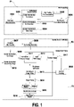
- Figure 1 shows the steps of a method according to an example.
- the method comprises a step S001 of reconstructing the 3D geometry of the scene. This can be done on the basis of an image of the scene (an RGB image or preferably an RGBD image, and eventually a plurality of images), and preferably the pose of the camera (at this stage, this pose can be provided).
- the output of this step is the 3D geometric model of the scene in the form of a 3D mesh.
- the 3D geometric model of the scene can be obtained by means of Truncated Signed Distance Field (TSDF) integration, which requires a depth image stream scanning the scene and the corresponding camera poses.
- TSDF Truncated Signed Distance Field
- the invention is not limited to the use of images to reconstruct the 3D geometry of the scene and can also use 3D geometry models prepared by an operator.
- This step uses as input the 3D geometry model of the scene, images of the scene and preferably camera poses.
- the method can include a step of obtaining image information of the scene.
- the radiosity can be measured (from image information) and used together with the scene geometry, to compute the irradiance, as will be shown hereinafter.
- Outdoor illumination complicates this procedure in two ways, first, it is not possible to reconstruct the outdoor geometry with current RGBD sensors, and the sky does not have a proper geometry in its common sense. Further, the sun radiosity is typically too high to be captured directly by consumer-grade RGBD cameras. The following described method overcomes this difficulty.
- steps S002, S003, and S004 are three alternative steps that can be used to obtain reflectance maps from image information (one or more images).
- Step S002 is an alternative which is only represented for the sake of completeness as it represents a case where there is no outdoor illumination.
- This step implements the method of document "Camera tracking in lighting adaptable maps of indoor environments” further discloses how to obtain radiosity maps/reflectance maps and of European Patent Application 20 154 742.9 filed on January 30, 2020 .
- Radiosity values B ( v i ) are recovered from scanning the scene with an RGB camera while varying the camera's exposure time.
- Step S003 actually part of the present invention, is a first alternative step of obtaining a reflectance map of the scene for the contribution of outdoor illumination to the scene based on the 3D geometry model of the scene.
- This alternative is particularly suitable for scenes which receive outdoor light but not direct sunlight.
- the brightness of the sky is low enough to be directly measured on image information with a consumer grade RGB(D) camera (i.e. the image information can be obtained by acquiring at least one image of the scene with this outside illumination).
- the radiosity can be measured as in the above described step S002, while the geometry outside this window is still missing (there are no vertices onto which the radiosity can be projected).
- the outdoor geometry is modeled as a sphere or a sky sphere.
- This sphere is formed by a set of sample points (i.e. light sources) placed on the sphere.
- Each point l ⁇ L is associated with a direction n ( l ) and a radiosity B ( l ) .
- This radiosity is recovered by projecting parts of the input image (or images if a plurality of images of the scene is used), which do not fall onto the scene geometry, onto the sky sphere instead.
- Step S004 is another alternative for recovering the reflectance map. This alternative is particularly suitable for applications where the scene will receive direct sunlight.
- the sun is considered to be directly visible from the inside, in the scene. Theoretically, this could be handled analogously to step S003, however, the minimal exposure time of most RGBD cameras is not short enough to capture the sun's radiosity. In other words, orienting a camera directly towards the sun does not allow measuring B ( l ) for a point placed on the sphere where the sun is l ⁇ L sun , with being a set of points placed where the sun is, better described hereinafter in reference to figure 2 .
- a meaningful scene reflectance can be estimated, in particular by using at least two images of the scene (from the image information) where the scene receives outdoor illumination and direct sunlight, taken at different instants associated with different positions of the sun.
- L t 1 sun be a set of points arranged on the above-mentioned sphere within the sun circle (the circle appearing where the sun is located), or in other words_the sky area covered by the sun at time t 1 (an instant at which a first image has been captured). Further, let V t 1 sun be the set of vertices lit by direct sun light, i.e. v ⁇ V t 1 sun if and only if F ( v,l ) G ( v,l ) > 0 for a given l ⁇ L t 1 sun .
- B t 1 ( l ) is the same for all l ⁇ L t 1 sun , and this leads to only having one unknown, the sun radiosity denoted B t 1 sun . It should be noted that for all other vertices not in V t 1 sun , it is possible to recover the reflectance as they only depend on the scene or sky radiosities, which can be measured.
- V t 2 sun be defined similarly to V t 1 sun and V t 1 ⁇ t 2 sun the set of vertices in V t 1 sun but not in V t 2 sun , i.e. lit by direct sunlight at t 1 but not at t 2 .
- E s ti v and E l ti v being respectively the irradiance from the scene and from the sky at instant ti .
- E l t 1 v E sky t 1 v + B t 1 sun ⁇ l ⁇ L t 1 sun F l v G l v
- Step S005 can then be carried out (this step is carried out before steps S003 and steps S004 as its output can be used in these steps) in which a ray tracing step is performed to determine the visibility of each vertex of the 3D geometric model.
- This step uses the 3D geometric model as input and the sky sphere separated into points/light sources, as defined above. This allows obtaining the visibility G in equations 4 and 5, for example through a pre-computation so that these equations can be solved later. This eliminates the main bulk of computation during illumination estimation.
- Step S006 can then be carried out in which a normalized radiosity map ( B ⁇ sky ) for the contribution of the sky to the outdoor illumination based on the reflectance map (obtained using either S003 or S004) is elaborated, and in which a normalized radiosity map ( B ⁇ gr ) for the contribution of the ground to the outdoor illumination based on the reflectance map is elaborated.
- a normalized radiosity map B ⁇ sky
- B ⁇ gr a normalized radiosity map for the contribution of the ground to the outdoor illumination based on the reflectance map
- obtaining a normalized radiosity map is performed using the algorithm known to the person skilled in the art as the radiosity algorithm ( Cindy M. Goral, Kenneth E. Torrance, Donald P. Greenberg, and Bennett Battaile. 1984. "Modeling the interaction of light between diffuse surfaces”. SIGGRAPH Comput. Graph. 18, 3 (July 1984), 213-222 ).
- the radiosity algorithm Go M. Goral, Kenneth E. Torrance, Donald P. Greenberg, and Bennett Battaile. 1984. "Modeling the interaction of light between diffuse surfaces”. SIGGRAPH Comput. Graph. 18, 3 (July 1984), 213-222 ).
- an iterative version of the radiosity algorithm is used.
- each vertex v ⁇ V has a reflectance p(v)
- the radiosity B(v) here is the amount of light reflected by the surface patch at v
- B x ( v ) is the radiosity from light source
- B 0 l v i ⁇ v i S l F l v i G l v i
- a simplified model consisting of sun, sky, and ground light components.
- the sky and ground components are computed by first splitting the sky sphere into two disjoints sets and , and adding the set of bins describing the sun area. Then, equation 3 can be used to compute the radiosity contributions of each of the three light sources.
- the sun, sky, and ground bins l have the same radiosities (or brightness scales) S sun , S sky , and S gr respectively, such that the term B ( l ) in equation 5 can be replaced by the proper brightness scale parameter S x , with x ⁇ sun, sky, gr ⁇ (with gr for ground).
- B ⁇ x is called a normalized radiosity.
- a second phase P2 can be carried out.
- this second phase can be carried out every 5 minutes, or any duration of the order of 5 minutes, as the sun moves slowly throughout the day.
- step S007 of the second phase the position of the sun is computed using the scene geolocation (i.e. latitude and longitude), the orientation of the scene, the time (i.e. yyyy.mm.dd.hh.mm.ss).
- the position of the sun can be expressed as a direction vector to reflect the sun direction relative to the scene.
- This step uses the sun position (for example expressed as a direction), it is possible to obtain the normalized radiosity map ( B ⁇ sun ) for the contribution of the sun to the outdoor illumination.
- This step also uses the reflectance map, the visibility terms G, and the 3D geometric model of the scene.
- B ⁇ sun should therefore be computed for every new sun position. Given that the sun area is much smaller than that of sky or ground, B ⁇ sun is obtained within a couple of minutes using GPU acceleration. Even though this update is not real-time, the sun position varies only very little in the course of minutes, and performing the steps of the second phase can be performed every couple minutes, typically every five minutes.
- the final and third phase P3 can be carried out in near real-time, that is to say within a duration which is less than the frame rate from the instant (t) at which it is desired to simulate the illumination.
- This phase comprises step S009 in which a normalized image I ⁇ t sun of the scene for the contribution of the sun to the outdoor illumination of the scene is rendered on the basis of B ⁇ sun .
- This step can use an initial pose estimate T t ⁇ .
- This pose is obtained because a frame-to-frame tracking method is used here.
- the change of camera pose is computed by matching an input image at instant t to the image of instant t-1.
- This tracking process is described in more detail in document " Camera Tracking in Lighting Adaptable Maps of Indoor Environments” (T. Caselitz, M. Krawez, J. Sundram, M. Van Loock and W. Burgard, 2020 IEEE International Conference on Robotics and Automation (ICRA), Paris, France, 2020, pp. 3334-3340 ).
- the tracking may be done using the method described in the previously mentioned European Patent Application.
- Step S010 comprises analogous steps for B ⁇ sky and B ⁇ gr in which normalized images are rendered (respectively I ⁇ t sky and I ⁇ t gr ).
- the normalized images can be combined in step S011.
- an image I C of the scene is acquired with the camera in step S012.
- step S013 a subset of pixels ⁇ of the pixels of the image I C are selected so as to represent the image areas with the most information about illumination and containing the least amount of noise/errors.
- a weight W spl can be used to represent the reliability of ⁇ for brightness scale estimation. This weight can either be set to 1, or be computed to reflect whether the sampled points are representative for the light distribution in the scene, and how much noise can be expected in these samples.
- the brightness scale estimation is carried out in step S014.
- I B ( u ) ⁇ x ⁇ sun,sky,gr ⁇ S x Î x (u), CRF () being the camera response function, and et the exposure time of I C .
- the brightness scale parameters are obtained by minimizing Err over S x . This minimization can be performed by means of a least squares solver.
- step S015 can be performed in which several frames are used.
- the simulated image I C ref in step S017 can be rendered using the rendered normalized images and the brightness scale parameters S sun , S sky , and S grd .
- Tracking of the camera position can then be performed in step S018 by comparing I C ref and I C . As explained above, tracking is performed using methods known to the person skilled in the art.
- Figure 2 is a 2D representation of a cross section of the above-mentioned sphere centered on the scene.
- the points considered to be light sources are aligned on the sphere. More precisely, the points of are aligned in the upper hemisphere while the points are aligned in the lower hemisphere. These points are spaced regularly around the sphere.
- a radiosity value is affected by projecting a portion of the image to the point li, as explained above.
- FIG. 3 shows a system 200 configured to perform the method described in reference to figure 1 .
- This system is equipped with a camera 201 (for example an RGBD camera), and has a computer structure.
- the system comprises a processor 202, and a nonvolatile memory 203.
- this nonvolatile memory 203 a set of computer program instructions is stored. When these instructions are executed by processor 202, the steps of the above defined method are performed.
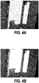
- Figure 4A is an image rendered by the present method, while Figure 4B is the actual image acquired by the camera. It can be scene that the illumination simulation provides a good simulation of the actual scene.
- Figure 5A is an image of a sphere of bins centered around the scene and determined in the above steps.
- Figure 5B shows how this sphere is seen from the camera: this is an approximation of the outside which does not take into account the exact geometry of the outside but provides a good estimation of the illumination.
Landscapes
- Engineering & Computer Science (AREA)
- Multimedia (AREA)
- Physics & Mathematics (AREA)
- Signal Processing (AREA)
- Computer Graphics (AREA)
- General Physics & Mathematics (AREA)
- Theoretical Computer Science (AREA)
- General Engineering & Computer Science (AREA)
- Electromagnetism (AREA)
- Image Processing (AREA)
- Image Generation (AREA)
Abstract
a first preliminary phase (P1) including:
obtaining (S003, S004) a reflectance map of the scene
elaborating normalized radiosity maps for the contribution of the sky and the ground,
a second phase (P2) carried out within a first given duration from the instant including:
obtaining (S007) the position of the sun,
obtaining (S008) a normalized radiosity map for the contribution of the sun,
a third phase (P3), including:
acquiring an image of the scene,
determining (S014, S015) brightness scale parameters for the ground, the sky, and the sun.
Description
- The present disclosure is related to the field of image processing, in particular to a method and system for simulating the illumination of an indoor scene observed by a camera.
- Visual camera tracking, or egomotion estimation, has been an important research field in robotics and computer vision. These methods provide the pose of a camera observing a scene.
- Direct methods to estimate a pose, which are based on measurements made from all the pixels to estimate the pose, have been observed to be more precise and robust than feature-based methods which only rely on a limited number of pixels.
- The performance of direct methods is known to be sensitive to illumination conditions. Document "Camera tracking in lighting adaptable maps of indoor environments" (T. Caselitz, M. Krawez, J. Sundram, M. Van Loock, and W. Burgard, in IEEE International Conference on Robotics and Automation (ICRA)) addressed this problem by adjusting a map to a current scene illumination. This map was represented by a 3D mesh with surface reflectance and radiosity information. The solution of this document consisted in detecting and segmenting artificial light sources (i.e. lamps), and to use the method known as "radiosity transport" from document "Modeling the interaction of light between diffuse surfaces" (C. M. Goral, K. E. Torrance, D. P. Greenberg, and B. Battaile, in ACM SIGGRAPH Computer Graphics, vol. 18, no. 3, 1984) to pre-compute the illumination components for each artificial light source. Tracking was described in this document as comprising the detection of the set of lamps currently switched on and combining the corresponding illumination components to predict the scene appearance in real time. Tracking against the adjusted map has been observed to be more stable than without illumination adaptation.
- This solution is limited to indoor scenes which are not affected by outdoor light. During daytime, indoor environment are typically illuminated by outdoor light coming through windows. Outdoor illumination depends on several parameters which change dynamically, and most importantly the position of the sun which changes through the course of the day. Weather conditions also contribute to rapid lighting changes, e.g. clouds moving in front of the sun. Because direct sun light usually alters the scene appearance more dramatically than artificial light sources, it is desirable to incorporate outdoor illumination into a predictive environment model.
- Consequently, it appears that the method of document "Camera tracking in lighting adaptable maps of indoor environments" cannot be used in situations where outdoor lighting affects the illumination.
- Outdoor illumination has been studied in different fields and more precisely in the field of augmented reality. Typically, outdoor illumination is taken into account to render a virtual object into a real scene. These solutions do not aim at obtaining a simulation of the illumination of the scene which matches the actual scene.
- The documents discussed below present the known prior art.
- Daylight modeling has also been used in architectural design and document "Daylight coefficients" ( P. R. Tregenza and I. Waters, Lighting Research & Technology, vol. 15, no. 2, pp. 65-71, 1983) discloses an illumination one such illumination model. Documents "Standard daylight coefficient model for dynamic daylighting simulations" (D. Bourgeois, C. F. Reinhart, and G. Ward, Building Research & Information, vol. 36, no. 1, pp. 68-82, 2008) and "A radiosity-based methodology considering urban environments for assessing daylighting," (G. Besuievsky, E. Fern'andez, J. P. Aguerre, and B. Beckers in Journal of Physics: Conference Series, vol. 1343, no. 1. IOP Publishing, 2019, p. 012156) disclose improvements to this model. These solutions cannot handle rapid changes of lights.
- Document "Revitage: Realistic virtual heritage taking shadows and sky illumination into account" (H. Kolivand, A. El Rhalibi, M. S. Sunar, and T. Saba, Journal of Cultural Heritage, vol. 32, pp. 166-175, 2018) discloses blending a virtual building model into a real outdoor scene. An atmosphere model is used in this document.
- Document "Real-time image based lighting for outdoor augmented reality under dynamically changing illumination conditions" (T. Jensen, M. S. Andersen, and C. B. Madsen, GRAPP, vol. 6, pp. 364-371, 2006), discloses a solution to illuminate an object with a static camera pose and is not applicable to the illumination of a scene.
- Document "Find your way by observing the sun and other semantic cues" (W.-C. Ma, S. Wang, M. A. Brubaker, S. Fidler, and R. Urtasun, in 2017 IEEE International Conference on Robotics and Automation (ICRA), IEEE, 2017, pp. 6292-6299) discloses a method to use sun direction to improve global outdoor localization in the context of autonomous driving. This document proposes to estimate the sun position relative to a carby using a Convolution Neural Network to obtain the car orientation by comparing it to the true sun direction computed in real time.
- Document "Improving the accuracy of stereo visual odometry using visual illumination estimation" (L. Clement, V. Peretroukhin, and J. Kelly, In International Symposium on Experimental Robotics. Springer, 2016) teaches to deploy the sun location to reduce angular drift in a visual odometry method.
Document "Simulation based camera localization under a variable lighting environment" (T. Mashita, A. Plopski, A. Kudo, T. H˙˙ollerer, K. Kiyokawa, and H. Takemura, in ICAT-EGVE, 2016, pp. 69-76) discloses a method for outdoor illumination prediction to improve feature-based localization. In this document, point features are detected on a 3D model of a building and then the feature appearance is predicted by rendering the model for different outdoor lighting conditions. The appearance variation of each feature point is stored as a distribution over the descriptor vectors and the document describes how those can be used for image matching. Document "Online tracking of outdoor lighting variations for augmented reality with moving cameras" (Y. Liu and X. Granier, IEEE Transactions on visualization and computer graphics, vol. 18, no. 4, pp. 573-580, 2012) proposes to estimate the dynamic sun and sky brightness in a video of an outdoor scene, captured by a moving camera. This document teaches to derive the sun position from geolocation and time, and also to assume that a coarse scene geometry is provided. In this document a simple shadow model is used. - The present disclosure overcomes one or more deficiencies of the prior art by proposing a method for simulating, at an instant, the illumination of an indoor scene observed by a camera and being illuminated by outdoor light, the method comprising:
- a first preliminary phase including:
- obtaining a 3D geometric model of the scene (i.e. a 3D mesh of the scene, either predetermined or computed from an image of the scene),
- obtaining image information of the scene (for example, image information can be acquired by an RGB or an RGBD sensor and can comprise one or more images, of a stream of images forming a video, for example with the camera being static or alternatively the camera moving),
- obtaining a reflectance map (i.e. a map which indicates a reflectance at each vertex in the 3D geometric model) of the scene for the contribution of outdoor illumination to the scene based on the 3D geometric model of the scene and the image information,
- elaborating a normalized radiosity map for the contribution of the sky to the outdoor illumination based on the reflectance map,
- elaborating a normalized radiosity map for the contribution of the ground to the outdoor illumination based on the reflectance map,
- a second phase carried out within a first given duration from the instant including:
- obtaining the position of the sun using the geolocation, the time, and the orientation of the scene (either provided or calculated from an acquired image),
- obtaining a normalized radiosity map for the contribution of the sun to the outdoor illumination based on the position of the sun and the reflectance map,
- a third phase carried out within a second given duration from the instant, shorter than the first given duration, including:
- acquiring at least one image of the scene (using the camera),
- determining from the at least one image a brightness scale parameter for the contribution of the ground, a brightness scale parameter for the contribution of the sky, and a brightness scale parameter for the contribution of the sun.
- The above method applies to indoor scenes which have an opening on the outside (windows, doors, etcs) though which outdoor illumination can propagate.
- The normalized radiosity maps and the corresponding brightness scale parameters form the simulation of the illumination of the indoor scene at the instant. By way of example, it is possible to render a simulated image of the scene from the radiosity maps and the brightness scale parameters, the rendered image being considered to be a simulation of the illumination in the present application. The invention is however not limited to rendering images and applies to other applications in which radiosity maps and brightness scale parameters are used to obtain a (non-normalized) radiosity map of the illumination of the scene, and this radiosity map can be considered to be a simulation of the illumination.
- Thus, the method proposes to leverage the lighting intensity obtained from the image acquired in the third phase to reflect the actual brightness in the scene, whereas many methods of the prior art propose to use an analytical model to obtain the brightness of various components.
- The preliminary phase can be performed once for an indoor scene. The second phase can be performed regularly, typically every 5 minutes (the first duration can be of the order of several minutes), as the sun moves slowly during the day. The third phase allows performing nearly real time computation and the second duration can be of less than a second, for example to reflect the framerate of the camera. Thus, using these three phases results in a simulation which better reflects the actual illumination, and which limits the computational complexity as a portion of the calculation is done once (first phase), at a low frequency (second phase), and in near real time (third phase).
- The reflectance is defined as the ratio between the incoming light and the reflected light (the radiosity) and can be defined for each vertex of the 3D geometry model. Document "Building dense reflectance maps of indoor environments using an rgb-d camera" (M. Krawez, T. Caselitz, D. Büscher, M. Van Loock, and W. Burgard, in 2018 IEEE/RSJ International Conference on Intelligent Robots and Systems (IROS). IEEE, 2018, pp. 3210-3217) discloses how to obtain reflectance maps and radiosity maps.
- The above cited document "Camera tracking in lighting adaptable maps of indoor environments" further discloses how to obtain radiosity maps/reflectance maps. Also, European Patent Application
20 154 742.9 filed on January 30, 2020 - In fact, the present method is based on the "radiosity transport" methods.
- It should be noted that in the present method, normalized radiosity maps are first obtained before radiosity maps. The wording "normalized" indicates that a scale parameter can multiply the normalized radiosity to obtain an actual radiosity map. In fact, a normalized radiosity map indicates the spatial light distribution in the scene induced by a light source (here light sources associated with the sky, the ground, and the sun, in other words outdoor light sources), with values being scalable so as to reach the actual light source brightness.
- Elaborating a normalized radiosity map includes affecting a normalized radiosity value to light sources corresponding to either the ground, the sky, or the sun. These light sources can be virtual (i.e. only existing in the calculations of the present method) and located (or considered to be located as they are virtual) where the sun/ground/sky are expected to be.
- It should be noted that the inventors of the present invention have observed that a good simulation is obtained by separating the light from the sky, the ground, and the sun (direct illumination) so that the third phase mainly comprises a determination of three brightness scale parameters: the computational complexity of the third phase is limited and the simulation is satisfactory.
- According to a particular embodiment, obtaining the reflectance map comprises considering a plurality of light sources arranged on a sphere centered on the scene.
- Thus, the light sources which are considered for the radiosity transport method, for example, are simulated light sources placed along a sphere. The number of light sources (points in space) to be considered can be chosen in accordance with an accuracy parameter depending on the application. The outside environment is thus simplified and does not take into account the exact geometry of, for example, buildings outside the indoor scene.
- By considered, what is meant is that in the reflectance calculation, light impinging on each surface (i.e. the radiosity) is considered to originate from one of these points (the above mentioned virtual light sources). Also, the expression "considered" indicates that each point will be taken into account for the calculation of the reflectance. Indeed, measured radiosity values can be obtained to recover the reflectance values in a manner known in itself in the art (for example known for indoor light sources).
- According to a particular embodiment, elaborating a normalized radiosity map for the contribution of the sky to the outdoor illumination based on the reflectance map comprises only considering the light sources in the upper half of the sphere, and elaborating a normalized radiosity map for the contribution of the ground to the outdoor illumination based on the reflectance map comprises only considering the light sources in the lower half of the sphere.
- The above mentioned sphere is cut in half horizontally to obtain two hemispheres, one used in the calculation of the radiosity map for illumination coming from the sky, one for the illumination coming from the ground.
- In this step, light sources/points in each hemisphere/half-sphere are each affected with a radiosity value.
- According to a particular embodiment, the preliminary phase comprises a ray-tracing step to determine the visibility of each vertex of the 3D geometric model, the method further comprising using the visibilities to obtain the normalized radiosity maps for the contribution of the sky, of the ground, and of the sun.
- This ray-tracing step can use predetermined pose information for the camera.
- Also, the visibility can be used in the step of obtaining a reflectance map.
- According to a particular embodiment, obtaining the reflectance map comprises using image information of the scene acquired when there is no direct sunlight entering the scene.
- This particular embodiment is adapted for indoor scenes that do not receive direct sunlight because of their orientation (and more precisely the direction in which their openings are facing).
- In a particular embodiment, which is an alternative to the previously defined particular embodiment, obtaining the reflectance map comprises using image information of the scene acquired when there is direct sunlight entering the scene at different instants associated with different positons of the sun.
- It has been observed that when there is direct sunlight entering a room, the minimal exposure time of most RGB-D cameras is not short enough to capture the sun's radiosity needed to recover the reflectance (i.e looking directly at the sun could not allow obtaining a radiosity value for a light source placed at the sun's position). However, by using image information acquired at different instants each associated with different sun positions, it has been observed that it is possible to obtain a reflectance map.
- According to a particular embodiment, the method comprises (in the third phase) rendering a normalized image of the scene for the contribution of the sky to the outdoor illumination of the scene based on the normalized radiosity map for the contribution of the sky to the outdoor illumination,
rendering a normalized image of the scene for the contribution of the ground to the outdoor illumination of the scene based on the normalized radiosity map for the contribution of the sky to the outdoor illumination, and
rendering a normalized image of the scene for the contribution of the sun to the outdoor illumination of the scene based on the normalized radiosity map for the contribution of the sky to the outdoor illumination. - Rendering these three images facilitates obtaining the brightness scale parameters.
- According to a particular embodiment, determining from the image a brightness scale parameter for the contribution of the ground, a brightness scale parameter for the contribution of the sky, and a brightness scale parameter for the contribution of the sun, comprises minimizing a difference between the image and a linear combination of the products of each brightness scale parameter with the corresponding normalized image.
- According to a particular embodiment, the third phase comprises acquiring a plurality of images of the scenes at different instants and determining the brightness scale parameters uses the plurality of images.
- By way of example, a sliding window may be used to collect continuously images of the scene and these images may also be used in the above mentioned minimization to obtain the brightness scale parameters.
- According to a particular embodiment, the method comprises elaborating an image of the scene from the normalized images of the scene and the brightness scale parameters.
- The invention also proposes a method for tracking the position of a camera observing a scene (also called visual odometry or egomotion) over a plurality of instants, using the simulated illumination of the indoor scene by the method for simulating the illumination of an indoor scene as defined above at every instant of the plurality of instants.
- The invention proposes to leverage information from the simulation results to perform the tracking, as this has been observed to be more robust than by using only images from the camera.
- The invention is therefore perfectly applicable in contexts where the pose of the camera changes.
- According to a particular embodiment, the method for simulating the illumination of an indoor scene is the method as defined above wherein normalized images rendered in accordance with the particular embodiment defined above, and wherein tracking is performed on the image elaborated from the normalized images of the scene and the brightness scale parameters.
- The invention also provides a system comprising a camera (RGB or RBGD) and a control unit configured to perform any embodiment of the method for simulating or the method for tracking as defined above.
- By way of example, this system can be a computer system.
- The invention also provides a vehicle including this system.
- In one particular embodiment, the steps of the method are determined by computer program instructions.
- Consequently, the invention is also directed to a computer program for executing the steps of a method as described above when this program is executed by a computer.
- This program can use any programming language and take the form of source code, object code or a code intermediate between source code and object code, such as a partially compiled form, or any other desirable form.
- The invention is also directed to a computer-readable information medium containing instructions of a computer program as described above.
- The information medium can be any entity or device capable of storing the program. For example, the medium can include storage means such as a ROM, for example a CD ROM or a microelectronic circuit ROM, or magnetic storage means, for example a diskette (floppy disk) or a hard disk.
- Alternatively, the information medium can be an integrated circuit in which the program is incorporated, the circuit being adapted to execute the method in question or to be used in its execution.
- How the present disclosure may be put into effect will now be described by way of example with reference to the appended drawings, in which:
-
figure 1 is a graphical representation of a pipeline to implement the steps of the method according to an example, -
figure 2 is a schematical representation of a sphere associated with outside illumination, -
figure 3 is a representation of a system according to an example, -
figure 4A is an image of an indoor scene andfigure 4B is the corresponding rendered image, -
figure 5A represents a sphere representing outdoor illumination andfigure 5B is a representation of how this sphere is observed from the inside. - An exemplary method for simulating the illumination of an indoor scene will now be described. This method aims at simulating the illumination of an indoor scene at a given instant, typically in near real time. Also, in the present description, the simulation is aimed at performing a tracking of the position of the camera observing the scene. The invention is however not limited to tracking this position and can also be applied to other applications in which it is required to use a simulation of the illumination.
- The method is advantageous as it limits the computational load to be performed in near real-time. This results from the fact that a portion of the computations is performed once, another portion is performed for example every five minutes, and the final portion is done in real time.
-
Figure 1 shows the steps of a method according to an example. In a first phase P1 (which needs be performed only once for a given scene), the method comprises a step S001 of reconstructing the 3D geometry of the scene. This can be done on the basis of an image of the scene (an RGB image or preferably an RGBD image, and eventually a plurality of images), and preferably the pose of the camera (at this stage, this pose can be provided). The output of this step is the 3D geometric model of the scene in the form of a 3D mesh. The 3D geometric model of the scene can be obtained by means of Truncated Signed Distance Field (TSDF) integration, which requires a depth image stream scanning the scene and the corresponding camera poses. It should be noted that if this method is used, the RGBD images should be acquired when there is no direct sun light visible in the scene as most RGBD cameras operate using a near-infrared sensor which fails in bright sun light. - The invention is not limited to the use of images to reconstruct the 3D geometry of the scene and can also use 3D geometry models prepared by an operator.
- Subsequently, a step in which reflectance maps (i.e. reflectance values at each vertex) will be acquired is performed. This step uses as input the 3D geometry model of the scene, images of the scene and preferably camera poses.
- While not represented, the method can include a step of obtaining image information of the scene.
- It should be noted that the reflectance ρ of a vertex vi is defined as the ratio between the incoming light E(vi) (also called the irradiance) and the reflected light B(vi) (also called the radiosity) at vertex vi:

- The radiosity can be measured (from image information) and used together with the scene geometry, to compute the irradiance, as will be shown hereinafter. Outdoor illumination complicates this procedure in two ways, first, it is not possible to reconstruct the outdoor geometry with current RGBD sensors, and the sky does not have a proper geometry in its common sense. Further, the sun radiosity is typically too high to be captured directly by consumer-grade RGBD cameras. The following described method overcomes this difficulty.
- More precisely, the subsequently described steps S002, S003, and S004 are three alternative steps that can be used to obtain reflectance maps from image information (one or more images).
- Step S002 is an alternative which is only represented for the sake of completeness as it represents a case where there is no outdoor illumination. This step implements the method of document "Camera tracking in lighting adaptable maps of indoor environments" further discloses how to obtain radiosity maps/reflectance maps and of European Patent Application
20 154 742.9 filed on January 30, 2020 - If the scene is lit by artificial light sources only, which are all inside the scene, it is possible to use the method known to the person skilled in the art as the "radiosity transport" method, which solves the equation system given by

- Radiosity values B(vi ) are recovered from scanning the scene with an RGB camera while varying the camera's exposure time.
- Step S003, actually part of the present invention, is a first alternative step of obtaining a reflectance map of the scene for the contribution of outdoor illumination to the scene based on the 3D geometry model of the scene. This alternative is particularly suitable for scenes which receive outdoor light but not direct sunlight. In this case, the the brightness of the sky is low enough to be directly measured on image information with a consumer grade RGB(D) camera (i.e. the image information can be obtained by acquiring at least one image of the scene with this outside illumination). In this step, it is considered that light is passing for example through a window but no direct sunlight is visible in the scene itself. Thus, the radiosity can be measured as in the above described step S002, while the geometry outside this window is still missing (there are no vertices onto which the radiosity can be projected).
- To overcome this difficulty, the outdoor geometry is modeled as a sphere or a sky sphere. This sphere is formed by a setof sample points (i.e. light sources) placed on the sphere. Each point


equation 2 can be used for reflectance recovery:
- Wherein Es is the irradiance from the scene and El is the irradiance from l, with:


- The above defined sphere will be better described in reference to
figure 2 . - Step S004 is another alternative for recovering the reflectance map. This alternative is particularly suitable for applications where the scene will receive direct sunlight.
- In this alternative, the sun is considered to be directly visible from the inside, in the scene. Theoretically, this could be handled analogously to step S003, however, the minimal exposure time of most RGBD cameras is not short enough to capture the sun's radiosity. In other words, orienting a camera directly towards the sun does not allow measuring B(l) for a point placed on the sphere where the sun is
 being a set of points placed where the sun is, better described hereinafter in reference to
figure 2 . - Thus, since the sun, if present/visible, is the dominant light source in the scene, we cannot reliably recover the reflectance using radiosity transport directly.
- Nevertheless, under certain assumptions and as will be described hereinafter, a meaningful scene reflectance can be estimated, in particular by using at least two images of the scene (from the image information) where the scene receives outdoor illumination and direct sunlight, taken at different instants associated with different positions of the sun.
-
Let 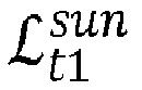


Let 


radiosity 


- With


- In equation 6, all quantities except


- With

equation 5 using sky radiosities at t1. Using this expression in equation 6 and solving it for

- It should be noted that all the values on the right side are known, thus, it is possible to compute

- Step S005 can then be carried out (this step is carried out before steps S003 and steps S004 as its output can be used in these steps) in which a ray tracing step is performed to determine the visibility of each vertex of the 3D geometric model. This step uses the 3D geometric model as input and the sky sphere separated into points/light sources, as defined above. This allows obtaining the visibility G in
equations - Step S006 can then be carried out in which a normalized radiosity map (B̂sky ) for the contribution of the sky to the outdoor illumination based on the reflectance map (obtained using either S003 or S004) is elaborated, and in which a normalized radiosity map (B̂gr ) for the contribution of the ground to the outdoor illumination based on the reflectance map is elaborated.
- In the present application, obtaining a normalized radiosity map is performed using the algorithm known to the person skilled in the art as the radiosity algorithm (Cindy M. Goral, Kenneth E. Torrance, Donald P. Greenberg, and Bennett Battaile. 1984. "Modeling the interaction of light between diffuse surfaces". SIGGRAPH Comput. Graph. 18, 3 (July 1984), 213-222). Preferably, an iterative version of the radiosity algorithm is used.
- At this stage, the reflectance of each vertex of the scene is known,
- It is possible to obtain the normalized radiosities from the light sources and their brightness, G, F, and the reflectance map. For example, each vertex v ∈ V has a reflectance p(v), the radiosity B(v) here is the amount of light reflected by the surface patch at v, and Bx (v) is the radiosity from light sourceIn order to estimate Bx (v), it is possible to first compute the radiosity Bl (v) induced by a single directional light source


- being the light reaching the scene directly from l, and
-


- To adapt the 3D geometric model to the current outdoor illumination in real time, a simplified model is used consisting of sun, sky, and ground light components. The radiosity of each vertex v is given by B(v)= Bsun (v) + Bsky (v) + Bgr (v). The sky and ground components are computed by first splitting the sky sphere into two disjoints setsand
 , and adding the set of bins
 describing the sun area. Then, equation 3 can be used to compute the radiosity contributions of each of the three light sources.
- Here, it is assumed that the sun, sky, and ground bins l have the same radiosities (or brightness scales) Ssun, Ssky, and Sgr respectively, such that the term B(l) in
equation 5 can be replaced by the proper brightness scale parameter Sx, with x ∈{sun, sky, gr} (with gr for ground). In this case, the linearity of the radiosity transport equations allows pulling out Sx from the computation and to scale the vertex radiosities subsequently, i.e. Bx (v) = B̂x (v)Sx. B̂x is called a normalized radiosity. - For the sky and the ground, it is possible to pre-compute the normalized radiosities to speed up the scene re-lighting. Given B̂sky and B̂sun for each vertex, these normalized radiosities will then be multiplied by the corresponding brightness scale parameters in near real time, around the instant at which it is desired to simulate the illumination.
- A second phase P2 can be carried out. By way of example this second phase can be carried out every 5 minutes, or any duration of the order of 5 minutes, as the sun moves slowly throughout the day.
- In step S007 of the second phase, the position of the sun is computed using the scene geolocation (i.e. latitude and longitude), the orientation of the scene, the time (i.e. yyyy.mm.dd.hh.mm.ss). The position of the sun can be expressed as a direction vector to reflect the sun direction relative to the scene.
- In order to simulate the sun illumination correctly, it is required to known the sun position relative to the scene at any given time. This can be calculated analytically by an astronomical model.
- Using the sun position (for example expressed as a direction), it is possible to obtain the normalized radiosity map (B̂sun ) for the contribution of the sun to the outdoor illumination. This step also uses the reflectance map, the visibility terms G, and the 3D geometric model of the scene.
- Unlike the sky and ground contributions, the sun changes its relative position to the scene depending on time, therefore a radiosity pre-computation carried out in the first phase is not possible. B̂sun should therefore be computed for every new sun position. Given that the sun area is much smaller than that of sky or ground, B̂sun is obtained within a couple of minutes using GPU acceleration. Even though this update is not real-time, the sun position varies only very little in the course of minutes, and performing the steps of the second phase can be performed every couple minutes, typically every five minutes.
- The final and third phase P3 can be carried out in near real-time, that is to say within a duration which is less than the frame rate from the instant (t) at which it is desired to simulate the illumination.
- This phase comprises step S009 in which a normalized image


- Step S010 comprises analogous steps for B̂sky and B̂gr in which normalized images are rendered (respectively


- The normalized images can be combined in step S011.
- Also, in the third phase, an image IC of the scene is acquired with the camera in step S012.
- The subsequent steps will describe how the brightness scale parameters) Ssun, Ssky, and Sgr are estimated from the normalized images and the acquired image.
- This will be done by adjusting brightness scale parameter values to fit the acquired image.
- In step S013, a subset of pixels Ω of the pixels of the image IC are selected so as to represent the image areas with the most information about illumination and containing the least amount of noise/errors.
- In fact, it has been observed that because


- Also, a weight Wspl can be used to represent the reliability of Ω for brightness scale estimation. This weight can either be set to 1, or be computed to reflect whether the sampled points are representative for the light distribution in the scene, and how much noise can be expected in these samples.
- The brightness scale estimation is carried out in step S014. For a single frame IC and the samples u ∈ Ω the following error Err is minimized for the three brightness scale parameters Ssun, Ssky, and Sgr :

- With IB (u) = Σ x∈{sun,sky,gr }SxÎx (u), CRF() being the camera response function, and et the exposure time of IC. The brightness scale parameters are obtained by minimizing Err over Sx. This minimization can be performed by means of a least squares solver.
- As an alternative to step S014, step S015 can be performed in which several frames are used.
- It has been observed that a single frame can still be error-prone, and that it is preferable to average Ssun, Ssky, and Sgr over multiple frames using Wspl and Err as weights. In order to cope with dynamic illumination (i.e. clouds passing in front of the sun), it is proposed to use a sliding window approach, where frames behind a time horizon are discarded. It is further proposed to filter out outliers which deviate too much from previous frames.
- Consequently, the simulated image

- Tracking of the camera position can then be performed in step S018 by comparing

-
Figure 2 is a 2D representation of a cross section of the above-mentioned sphere centered on the scene. As can be seen on the figure, the points considered to be light sources are aligned on the sphere. More precisely, the points ofare aligned in the upper hemisphere while the points are aligned in the lower hemisphere. These points are spaced regularly around the sphere.
- Also, on this figure, for each point lif, the direction n(li ) is represented by an arrow.
- It should be noted that for the sun, a limited number of points are used where the sun appears to be when seen from the scene (points). The points of
 are more densely spaced than the points of
 and
and .
.
- In order to recover the reflectance in either step S003 or step S004, a radiosity value is affected by projecting a portion of the image to the point li, as explained above.
-
Figure 3 shows asystem 200 configured to perform the method described in reference tofigure 1 . This system is equipped with a camera 201 (for example an RGBD camera), and has a computer structure. The system comprises aprocessor 202, and anonvolatile memory 203. In thisnonvolatile memory 203, a set of computer program instructions is stored. When these instructions are executed byprocessor 202, the steps of the above defined method are performed. -
Figure 4A is an image rendered by the present method, whileFigure 4B is the actual image acquired by the camera. It can be scene that the illumination simulation provides a good simulation of the actual scene. -
Figure 5A is an image of a sphere of bins centered around the scene and determined in the above steps. -
Figure 5B shows how this sphere is seen from the camera: this is an approximation of the outside which does not take into account the exact geometry of the outside but provides a good estimation of the illumination. - Throughout the description, including the claims, the term "comprising a" should be understood as being synonymous with "comprising at least one" unless otherwise stated. In addition, any range set forth in the description, including the claims should be understood as including its end value(s) unless otherwise stated. Specific values for described elements should be understood to be within accepted manufacturing or industry tolerances known to one of skill in the art, and any use of the terms "substantially" and/or "approximately" and/or "generally" should be understood to mean falling within such accepted tolerances.
- Although the present disclosure herein has been described with reference to particular embodiments, it is to be understood that these embodiments are merely illustrative of the principles and applications of the present disclosure.
- It is intended that the specification and examples be considered as exemplary only, with a true scope of the disclosure being indicated by the following claims.
Claims (15)
- A method for simulating, at an instant, the illumination of an indoor scene observed by a camera and being illuminated by outdoor light, the method comprising:a first preliminary phase (P1) including:obtaining (S001)a 3D geometric model of the scene,obtaining image information of the scene,obtaining (S003, S004) a reflectance map of the scene for the contribution of outdoor illumination to the scene based on the 3D geometric model of the scene and the image information of the scene,elaborating (S006) a normalized radiosity map (B̂sky) for the contribution of the sky to the outdoor illumination based on the reflectance map,elaborating (S006) a normalized radiosity map (B̂gr ) for the contribution of the ground to the outdoor illumination based on the reflectance map,a second phase (P2) carried out within a first given duration from the instant including:obtaining (S007) the position of the sun using the geolocation, the time, and the orientation of the scene,obtaining (S008) a normalized radiosity map for the contribution of the sun (B̂sun ) to the outdoor illumination based on the position of the sun and the reflectance map,a third phase (P3) carried out within a second given duration from the instant (t), shorter than the first given duration, including:acquiring at least one image (IC ) of the scene,determining (S014, S015) from the at least one image a brightness scale parameter for the contribution of the ground (Sgr ), a brightness scale parameter for the contribution of the sky (Ssky ), and a brightness scale parameter for the contribution of the sun (Ssun ).
- The method of claim 1, wherein obtaining the reflectance map comprises considering a plurality of light sources () arranged on a sphere centered on the scene.

- The method of claim 2, wherein elaborating a normalized radiosity map for the contribution of the sky to the outdoor illumination based on the reflectance map comprises only considering the light sources in the upper half of the sphere, and elaborating a normalized radiosity map for the contribution of the ground to the outdoor illumination based on the reflectance map comprises only considering the light sources in the lower half of the sphere.
- The method of any one of claims 1 to 3, wherein the preliminary phase comprises a ray-tracing step (S005) to determine the visibility of each vertex of the 3D geometric model, the method further comprising using the visibilities to obtain the normalized radiosity maps for the contribution of the sky, of the ground, and of the sun.
- The method of any one of claims 1 to 4, wherein obtaining (S003) the reflectance map comprises using image information of the scene acquired when there is no direct sunlight entering the scene.
- The method of any one of claims 1 to 4, wherein obtaining (S004) the reflectance map comprises using image information of the scene acquired when there is direct sunlight entering the scene at different instants associated with different positions of the sun.
- The method of any one of claims 1 to 6, comprising rendering (S010) a normalized image of the scene for the contribution of the sky to the outdoor illumination of the scene

rendering (S010) a normalized image of the scene for the contribution of the ground to the outdoor illumination of the scene
rendering (S009) a normalized image of the scene for the contribution of the sun to the outdoor illumination of the scene
- The method of claim 7, wherein determining from the image a brightness scale parameter for the contribution of the ground, a brightness scale parameter for the contribution of the sky, and a brightness scale parameter for the contribution of the sun, comprises minimizing a difference (Err) between the image and a linear combination of the products of each brightness scale parameter with the corresponding normalized image.
- The method of any one of claims 1 to 8, wherein the third phase comprises acquiring a plurality of images of the scenes at different instants and determining the brightness scale parameters uses the plurality of images.
- The method of any one of claims 7 to 9 when in combination with at least claim 7, comprising elaborating (S017) an image of the scene from the normalized images of the scene and the brightness scale parameters.
- A method for tracking the position of a camera observing a scene over a plurality of instants, using the simulated illumination of the indoor scene by the method for simulating the illumination of an indoor scene in accordance with any one of claims 1 to 10 at every instant of the plurality of instants.
- The method of claim 10, wherein the method for simulating the illumination of an indoor scene is the method in accordance with claim 10, and wherein tracking is performed on the image elaborated from the normalized images of the scene and the brightness scale parameters.
- A system comprising a camera and a control unit configured to perform the method according to any one of claims 1 to 12.
- A computer program including instructions for executing the steps of a method according to any one of claims 1 to 12 when said program is executed by a computer.
- A recording medium readable by a computer and having recorded thereon a computer program including instructions for executing the steps of a method according to any one of claims 1 to 12.
Priority Applications (2)
| Application Number | Priority Date | Filing Date | Title |
|---|---|---|---|
| EP21159737.2A EP4050568B1 (en) | 2021-02-26 | 2021-02-26 | A method for simulating the illumination of an indoor scene observed by a camera illuminated by outdoor light |
| US17/679,597 US12160557B2 (en) | 2021-02-26 | 2022-02-24 | Method for simulating the illumination of an indoor scene observed by a camera illuminated by outdoor light and system |
Applications Claiming Priority (1)
| Application Number | Priority Date | Filing Date | Title |
|---|---|---|---|
| EP21159737.2A EP4050568B1 (en) | 2021-02-26 | 2021-02-26 | A method for simulating the illumination of an indoor scene observed by a camera illuminated by outdoor light |
Publications (2)
| Publication Number | Publication Date |
|---|---|
| EP4050568A1 true EP4050568A1 (en) | 2022-08-31 |
| EP4050568B1 EP4050568B1 (en) | 2025-06-25 |
Family
ID=74844703
Family Applications (1)
| Application Number | Title | Priority Date | Filing Date |
|---|---|---|---|
| EP21159737.2A Active EP4050568B1 (en) | 2021-02-26 | 2021-02-26 | A method for simulating the illumination of an indoor scene observed by a camera illuminated by outdoor light |
Country Status (2)
| Country | Link |
|---|---|
| US (1) | US12160557B2 (en) |
| EP (1) | EP4050568B1 (en) |
Families Citing this family (3)
| Publication number | Priority date | Publication date | Assignee | Title |
|---|---|---|---|---|
| US12579729B2 (en) * | 2021-04-07 | 2026-03-17 | Interdigital Ce Patent Holdings, Sas | Volumetric video supporting light effects |
| US11962880B2 (en) * | 2021-10-29 | 2024-04-16 | Comcast Cable Communications, Llc | Systems and methods for enhanced performance of camera devices |
| CN117689596A (en) * | 2022-09-01 | 2024-03-12 | 完美世界(北京)软件科技发展有限公司 | Illumination information calculation method and device, storage medium, computer equipment |
Citations (1)
| Publication number | Priority date | Publication date | Assignee | Title |
|---|---|---|---|---|
| US20170345208A1 (en) * | 2011-04-14 | 2017-11-30 | Suntracker Technologies Ltd. | System and method for real time dynamic lighting simulation |
Family Cites Families (2)
| Publication number | Priority date | Publication date | Assignee | Title |
|---|---|---|---|---|
| US10289094B2 (en) * | 2011-04-14 | 2019-05-14 | Suntracker Technologies Ltd. | System and method for the optimization of radiance modelling and controls in predictive daylight harvesting |
| EP3859684A1 (en) | 2020-01-30 | 2021-08-04 | Toyota Jidosha Kabushiki Kaisha | Method and system for building a lighting adaptable map of an indoor scene and using it for estimating an unknown light setting |
-
2021
- 2021-02-26 EP EP21159737.2A patent/EP4050568B1/en active Active
-
2022
- 2022-02-24 US US17/679,597 patent/US12160557B2/en active Active
Patent Citations (1)
| Publication number | Priority date | Publication date | Assignee | Title |
|---|---|---|---|---|
| US20170345208A1 (en) * | 2011-04-14 | 2017-11-30 | Suntracker Technologies Ltd. | System and method for real time dynamic lighting simulation |
Non-Patent Citations (20)
| Title |
|---|
| AYOUB MOHAMMED ED - HO YUN JAE ET AL: "A review on light transport algorithms and simulation tools to model daylighting inside buildings", SOLAR ENERGY, ELSEVIER LTD, vol. 198, 13 February 2020 (2020-02-13), pages 623 - 642, XP086046170, ISSN: 0038-092X, DOI: 10.1016/J.SOLENER.2020.02.018 * |
| C. M. GORALK. E. TORRANCED. P. GREENBERGB. BATTAILE: "Modeling the interaction of light between diffuse surfaces", ACM SIGGRAPH COMPUTER GRAPHICS, vol. 18, no. 3, 1984 |
| CASELITZ TIM ET AL: "Camera Tracking in Lighting Adaptable Maps of Indoor Environments", 2020 IEEE INTERNATIONAL CONFERENCE ON ROBOTICS AND AUTOMATION (ICRA), IEEE, 31 May 2020 (2020-05-31), pages 3334 - 3340, XP033826802, DOI: 10.1109/ICRA40945.2020.9197471 * |
| CINDY M. GORALKENNETH E. TORRANCEDONALD P. GREENBERGBENNETT BATTAILE: "Modeling the interaction of light between diffuse surfaces", SIGGRAPH COMPUT. GRAPH., vol. 18, no. 3, July 1984 (1984-07-01), pages 213 - 222 |
| D. BOURGEOISC. F. REINHARTG. WARD: "Standard daylight coefficient model for dynamic daylighting simulations", BUILDING RESEARCH & INFORMATION, vol. 36, no. 1, 2008, pages 68 - 82 |
| G. BESUIEVSKYE. FERN'ANDEZJ. P. AGUERREB. BECKERS: "Journal of Physics: Conference Series", vol. 1343, 2019, IOP PUBLISHING, article "A radiosity-based methodology considering urban environments for assessing daylighting", pages: 012156 |
| H. KOLIVANDA. EL RHALIBIM. S. SUNART. SABA: "Revitage: Realistic virtual heritage taking shadows and sky illumination into account", JOURNAL OF CULTURAL HERITAGE, vol. 32, 2018, pages 166 - 175 |
| KRAWEZ MICHAEL ET AL: "Building Dense Reflectance Maps of Indoor Environments Using an RGB-D Camera", 2018 IEEE/RSJ INTERNATIONAL CONFERENCE ON INTELLIGENT ROBOTS AND SYSTEMS (IROS), IEEE, 1 October 2018 (2018-10-01), pages 3210 - 3217, XP033491392, DOI: 10.1109/IROS.2018.8594107 * |
| KRAWEZ MICHAEL ET AL: "Real-Time Outdoor Illumination Estimation for Camera Tracking in Indoor Environments", IEEE ROBOTICS AND AUTOMATION LETTERS, IEEE, vol. 6, no. 3, 18 June 2021 (2021-06-18), pages 6084 - 6091, XP011864675, DOI: 10.1109/LRA.2021.3090455 * |
| L. CLEMENTV. PERETROUKHINJ. KELLY: "In International Symposium on Experimental Robotics", 2016, SPRINGER, article "Improving the accuracy of stereo visual odometry using visual illumination estimation" |
| M. KRAWEZT. CASELITZD. BUSCHERM. VAN LOOCKW. BURGARD: "2018 IEEE/RSJ International Conference on Intelligent Robots and Systems (IROS", 2018, IEEE, article "Building dense reflectance maps of indoor environments using an rgb-d camera", pages: 3210 - 3217 |
| MASAKI INABA ET AL: "Achieving robust alignment for outdoor mixed reality using 3D range data", VIRTUAL REALITY SOFTWARE AND TECHNOLOGY, ACM, 2 PENN PLAZA, SUITE 701 NEW YORK NY 10121-0701 USA, 10 December 2012 (2012-12-10), pages 61 - 68, XP058010143, ISBN: 978-1-4503-1469-5, DOI: 10.1145/2407336.2407348 * |
| P. R. TREGENZAI. WATERS: "Daylight coefficients", LIGHTING RESEARCH & TECHNOLOGY, vol. 15, no. 2, 1983, pages 65 - 71 |
| T. CASELITZM. KRAWEZJ. SUNDRAMM. VAN LOOCKW. BURGARD: "Camera Tracking in Lighting Adaptable Maps of Indoor Environments", 2020 IEEE INTERNATIONAL CONFERENCE ON ROBOTICS AND AUTOMATION (ICRA, 2020, pages 3334 - 3340, XP033826802, DOI: 10.1109/ICRA40945.2020.9197471 |
| T. CASELITZM. KRAWEZJ. SUNDRAMM. VAN LOOCKW. BURGARD: "Camera tracking in lighting adaptable maps of indoor environments", IEEE INTERNATIONAL CONFERENCE ON ROBOTICS AND AUTOMATION (ICRA |
| T. JENSENM. S. ANDERSENC. B. MADSEN: "Real-time image based lighting for outdoor augmented reality under dynamically changing illumination conditions", GRAPP, vol. 6, 2006, pages 364 - 371, XP055300591 |
| T. MASHITAA. PLOPSKIA. KUDOT. H'' OLLERERK. KIYOKAWAH. TAKEMURA: "Simulation based camera localization under a variable lighting environment", ICAT-EGVE, 2016, pages 69 - 76 |
| THORSTEN GROSCH ET AL: "Consistent interactive augmentation of live camera images with correct near-field illumination", VRST '07: PROCEEDINGS OF THE 2007 ACM SYMPOSIUM ON VIRTUAL REALITY SOFTWARE AND TECHNOLOGY, NEW YORK, NY : ACM PRESS, US, 5 November 2007 (2007-11-05), pages 125 - 132, XP058326106, ISBN: 978-1-59593-863-3, DOI: 10.1145/1315184.1315207 * |
| W.-C. MAS. WANGM. A. BRUBAKERS. FIDLERR. URTASUN: "2017 IEEE International Conference on Robotics and Automation (ICRA", 2017, IEEE, article "Find your way by observing the sun and other semantic cues", pages: 6292 - 6299 |
| Y. LIUX. GRANIER: "Online tracking of outdoor lighting variations for augmented reality with moving cameras", IEEE TRANSACTIONS ON VISUALIZATION AND COMPUTER GRAPHICS, vol. 18, no. 4, 2012, pages 573 - 580 |
Also Published As
| Publication number | Publication date |
|---|---|
| EP4050568B1 (en) | 2025-06-25 |
| US20220279156A1 (en) | 2022-09-01 |
| US12160557B2 (en) | 2024-12-03 |
Similar Documents
| Publication | Publication Date | Title |
|---|---|---|
| US12160557B2 (en) | Method for simulating the illumination of an indoor scene observed by a camera illuminated by outdoor light and system | |
| Ikeuchi et al. | Determining reflectance properties of an object using range and brightness images | |
| US9940725B2 (en) | Method for estimating the speed of movement of a camera | |
| KR20210119417A (en) | Depth estimation | |
| CN111462207A (en) | RGB-D simultaneous positioning and map creation method integrating direct method and feature method | |
| US20050212794A1 (en) | Method and apparatus for removing of shadows and shadings from texture images | |
| WO2014202258A1 (en) | A method for mapping an environment | |
| US11082633B2 (en) | Method of estimating the speed of displacement of a camera | |
| CA2573318C (en) | Geospatial image change detecting system with environmental enhancement and associated methods | |
| CA2573291C (en) | Environmental condition detecting system using geospatial images and associated methods | |
| US20240386656A1 (en) | Deferred neural lighting in augmented image generation | |
| CN113269861A (en) | Method and system for constructing illumination adaptive map of indoor scene and estimating unknown light setting by using illumination adaptive map | |
| Sequeira et al. | 3D reconstruction of indoor environments | |
| CN120252680A (en) | A SLAM positioning method and system based on multi-sensor fusion | |
| CN116940969A (en) | Visual inertial SLAM system | |
| WO2024043263A1 (en) | Information processing device, information processing system, information processing method, and computer program | |
| US12541916B2 (en) | Method for assessing the physically based simulation quality of a glazed object | |
| Piccolo et al. | Resource-Constrained Vision-Based Relative Navigation About Small Bodies | |
| Ayadi et al. | A skyline-based approach for mobile augmented reality | |
| WO2024043119A1 (en) | Information processing device, information processing system, information processing method, and computer program | |
| Bradley et al. | Georeferenced mosaics for tracking fires using unmanned miniature air vehicles | |
| Lee et al. | Road following in an unstructured desert environment based on the EM (expectation-maximization) algorithm | |
| Ling et al. | An iterated extended Kalman filter for 3D mapping via Kinect camera | |
| Lee et al. | Online Image Pre-processing Using Bayesian Optimization for Visual-inertial Odometry | |
| Masuda et al. | Sunlight illumination simulation for archaeological investigation-case study of the fugoppe cave |
Legal Events
| Date | Code | Title | Description |
|---|---|---|---|
| PUAI | Public reference made under article 153(3) epc to a published international application that has entered the european phase |
Free format text: ORIGINAL CODE: 0009012 |
|
| STAA | Information on the status of an ep patent application or granted ep patent |
Free format text: STATUS: REQUEST FOR EXAMINATION WAS MADE |
|
| 17P | Request for examination filed |
Effective date: 20210226 |
|
| AK | Designated contracting states |
Kind code of ref document: A1 Designated state(s): AL AT BE BG CH CY CZ DE DK EE ES FI FR GB GR HR HU IE IS IT LI LT LU LV MC MK MT NL NO PL PT RO RS SE SI SK SM TR |
|
| GRAP | Despatch of communication of intention to grant a patent |
Free format text: ORIGINAL CODE: EPIDOSNIGR1 |
|
| STAA | Information on the status of an ep patent application or granted ep patent |
Free format text: STATUS: GRANT OF PATENT IS INTENDED |
|
| INTG | Intention to grant announced |
Effective date: 20250212 |
|
| GRAS | Grant fee paid |
Free format text: ORIGINAL CODE: EPIDOSNIGR3 |
|
| GRAA | (expected) grant |
Free format text: ORIGINAL CODE: 0009210 |
|
| STAA | Information on the status of an ep patent application or granted ep patent |
Free format text: STATUS: THE PATENT HAS BEEN GRANTED |
|
| AK | Designated contracting states |
Kind code of ref document: B1 Designated state(s): AL AT BE BG CH CY CZ DE DK EE ES FI FR GB GR HR HU IE IS IT LI LT LU LV MC MK MT NL NO PL PT RO RS SE SI SK SM TR |
|
| REG | Reference to a national code |
Ref country code: GB Ref legal event code: FG4D |
|
| REG | Reference to a national code |
Ref country code: CH Ref legal event code: EP |
|
| REG | Reference to a national code |
Ref country code: CH Ref legal event code: EP |
|
| REG | Reference to a national code |
Ref country code: IE Ref legal event code: FG4D |
|
| REG | Reference to a national code |
Ref country code: DE Ref legal event code: R096 Ref document number: 602021032672 Country of ref document: DE |
|
| REG | Reference to a national code |
Ref country code: DE Ref legal event code: R081 Ref document number: 602021032672 Country of ref document: DE Owner name: ALBERT-LUDWIGS-UNIVERSITAET FREIBURG, KOERPERS, DE Free format text: FORMER OWNER: ANMELDERANGABEN UNKLAR / UNVOLLSTAENDIG, 80297 MUENCHEN, DE Ref country code: DE Ref legal event code: R081 Ref document number: 602021032672 Country of ref document: DE Owner name: TOYOTA JIDOSHA KABUSHIKI KAISHA, TOYOTA-SHI, JP Free format text: FORMER OWNER: ANMELDERANGABEN UNKLAR / UNVOLLSTAENDIG, 80297 MUENCHEN, DE |
|
| PG25 | Lapsed in a contracting state [announced via postgrant information from national office to epo] |
Ref country code: FI Free format text: LAPSE BECAUSE OF FAILURE TO SUBMIT A TRANSLATION OF THE DESCRIPTION OR TO PAY THE FEE WITHIN THE PRESCRIBED TIME-LIMIT Effective date: 20250625 |
|
| REG | Reference to a national code |
Ref country code: LT Ref legal event code: MG9D |
|
| PG25 | Lapsed in a contracting state [announced via postgrant information from national office to epo] |
Ref country code: NO Free format text: LAPSE BECAUSE OF FAILURE TO SUBMIT A TRANSLATION OF THE DESCRIPTION OR TO PAY THE FEE WITHIN THE PRESCRIBED TIME-LIMIT Effective date: 20250925 Ref country code: GR Free format text: LAPSE BECAUSE OF FAILURE TO SUBMIT A TRANSLATION OF THE DESCRIPTION OR TO PAY THE FEE WITHIN THE PRESCRIBED TIME-LIMIT Effective date: 20250926 |
|
| PG25 | Lapsed in a contracting state [announced via postgrant information from national office to epo] |
Ref country code: BG Free format text: LAPSE BECAUSE OF FAILURE TO SUBMIT A TRANSLATION OF THE DESCRIPTION OR TO PAY THE FEE WITHIN THE PRESCRIBED TIME-LIMIT Effective date: 20250625 |
|
| PG25 | Lapsed in a contracting state [announced via postgrant information from national office to epo] |
Ref country code: HR Free format text: LAPSE BECAUSE OF FAILURE TO SUBMIT A TRANSLATION OF THE DESCRIPTION OR TO PAY THE FEE WITHIN THE PRESCRIBED TIME-LIMIT Effective date: 20250625 |
|
| PG25 | Lapsed in a contracting state [announced via postgrant information from national office to epo] |
Ref country code: RS Free format text: LAPSE BECAUSE OF FAILURE TO SUBMIT A TRANSLATION OF THE DESCRIPTION OR TO PAY THE FEE WITHIN THE PRESCRIBED TIME-LIMIT Effective date: 20250925 |
|
| PG25 | Lapsed in a contracting state [announced via postgrant information from national office to epo] |
Ref country code: LV Free format text: LAPSE BECAUSE OF FAILURE TO SUBMIT A TRANSLATION OF THE DESCRIPTION OR TO PAY THE FEE WITHIN THE PRESCRIBED TIME-LIMIT Effective date: 20250625 |
|
| REG | Reference to a national code |
Ref country code: NL Ref legal event code: MP Effective date: 20250625 |
|
| PG25 | Lapsed in a contracting state [announced via postgrant information from national office to epo] |
Ref country code: NL Free format text: LAPSE BECAUSE OF FAILURE TO SUBMIT A TRANSLATION OF THE DESCRIPTION OR TO PAY THE FEE WITHIN THE PRESCRIBED TIME-LIMIT Effective date: 20250625 |
|
| PG25 | Lapsed in a contracting state [announced via postgrant information from national office to epo] |
Ref country code: PT Free format text: LAPSE BECAUSE OF FAILURE TO SUBMIT A TRANSLATION OF THE DESCRIPTION OR TO PAY THE FEE WITHIN THE PRESCRIBED TIME-LIMIT Effective date: 20251027 |
|
| REG | Reference to a national code |
Ref country code: AT Ref legal event code: MK05 Ref document number: 1807330 Country of ref document: AT Kind code of ref document: T Effective date: 20250625 |
|
| PG25 | Lapsed in a contracting state [announced via postgrant information from national office to epo] |
Ref country code: IS Free format text: LAPSE BECAUSE OF FAILURE TO SUBMIT A TRANSLATION OF THE DESCRIPTION OR TO PAY THE FEE WITHIN THE PRESCRIBED TIME-LIMIT Effective date: 20251025 |
|
| PG25 | Lapsed in a contracting state [announced via postgrant information from national office to epo] |
Ref country code: AT Free format text: LAPSE BECAUSE OF FAILURE TO SUBMIT A TRANSLATION OF THE DESCRIPTION OR TO PAY THE FEE WITHIN THE PRESCRIBED TIME-LIMIT Effective date: 20250625 Ref country code: SM Free format text: LAPSE BECAUSE OF FAILURE TO SUBMIT A TRANSLATION OF THE DESCRIPTION OR TO PAY THE FEE WITHIN THE PRESCRIBED TIME-LIMIT Effective date: 20250625 |
|
| PG25 | Lapsed in a contracting state [announced via postgrant information from national office to epo] |
Ref country code: CZ Free format text: LAPSE BECAUSE OF FAILURE TO SUBMIT A TRANSLATION OF THE DESCRIPTION OR TO PAY THE FEE WITHIN THE PRESCRIBED TIME-LIMIT Effective date: 20250625 |
|
| PG25 | Lapsed in a contracting state [announced via postgrant information from national office to epo] |
Ref country code: PL Free format text: LAPSE BECAUSE OF FAILURE TO SUBMIT A TRANSLATION OF THE DESCRIPTION OR TO PAY THE FEE WITHIN THE PRESCRIBED TIME-LIMIT Effective date: 20250625 |
|
| PG25 | Lapsed in a contracting state [announced via postgrant information from national office to epo] |
Ref country code: EE Free format text: LAPSE BECAUSE OF FAILURE TO SUBMIT A TRANSLATION OF THE DESCRIPTION OR TO PAY THE FEE WITHIN THE PRESCRIBED TIME-LIMIT Effective date: 20250625 |
|
| PG25 | Lapsed in a contracting state [announced via postgrant information from national office to epo] |
Ref country code: SK Free format text: LAPSE BECAUSE OF FAILURE TO SUBMIT A TRANSLATION OF THE DESCRIPTION OR TO PAY THE FEE WITHIN THE PRESCRIBED TIME-LIMIT Effective date: 20250625 |
|
| PG25 | Lapsed in a contracting state [announced via postgrant information from national office to epo] |
Ref country code: ES Free format text: LAPSE BECAUSE OF FAILURE TO SUBMIT A TRANSLATION OF THE DESCRIPTION OR TO PAY THE FEE WITHIN THE PRESCRIBED TIME-LIMIT Effective date: 20250625 |
|
| PG25 | Lapsed in a contracting state [announced via postgrant information from national office to epo] |
Ref country code: DK Free format text: LAPSE BECAUSE OF FAILURE TO SUBMIT A TRANSLATION OF THE DESCRIPTION OR TO PAY THE FEE WITHIN THE PRESCRIBED TIME-LIMIT Effective date: 20250625 |
|
| PGFP | Annual fee paid to national office [announced via postgrant information from national office to epo] |
Ref country code: DE Payment date: 20260102 Year of fee payment: 6 |
|
| PG25 | Lapsed in a contracting state [announced via postgrant information from national office to epo] |
Ref country code: IT Free format text: LAPSE BECAUSE OF FAILURE TO SUBMIT A TRANSLATION OF THE DESCRIPTION OR TO PAY THE FEE WITHIN THE PRESCRIBED TIME-LIMIT Effective date: 20250625 |
|
| PLBE | No opposition filed within time limit |
Free format text: ORIGINAL CODE: 0009261 |
|
| STAA | Information on the status of an ep patent application or granted ep patent |
Free format text: STATUS: NO OPPOSITION FILED WITHIN TIME LIMIT |
|
| REG | Reference to a national code |
Ref country code: CH Ref legal event code: L10 Free format text: ST27 STATUS EVENT CODE: U-0-0-L10-L00 (AS PROVIDED BY THE NATIONAL OFFICE) Effective date: 20260507 |