EP4050378A1 - Obstacle identification method and apparatus, self-moving device and storage medium - Google Patents
Obstacle identification method and apparatus, self-moving device and storage medium Download PDFInfo
- Publication number
- EP4050378A1 EP4050378A1 EP21793582.4A EP21793582A EP4050378A1 EP 4050378 A1 EP4050378 A1 EP 4050378A1 EP 21793582 A EP21793582 A EP 21793582A EP 4050378 A1 EP4050378 A1 EP 4050378A1
- Authority
- EP
- European Patent Office
- Prior art keywords
- line laser
- obstacle
- contour
- determining
- vertical distance
- Prior art date
- Legal status (The legal status is an assumption and is not a legal conclusion. Google has not performed a legal analysis and makes no representation as to the accuracy of the status listed.)
- Withdrawn
Links
Images



Classifications
-
- G—PHYSICS
- G01—MEASURING; TESTING
- G01S—RADIO DIRECTION-FINDING; RADIO NAVIGATION; DETERMINING DISTANCE OR VELOCITY BY USE OF RADIO WAVES; LOCATING OR PRESENCE-DETECTING BY USE OF THE REFLECTION OR RERADIATION OF RADIO WAVES; ANALOGOUS ARRANGEMENTS USING OTHER WAVES
- G01S17/00—Systems using the reflection or reradiation of electromagnetic waves other than radio waves, e.g. lidar systems
- G01S17/88—Lidar systems specially adapted for specific applications
- G01S17/93—Lidar systems specially adapted for specific applications for anti-collision purposes
- G01S17/931—Lidar systems specially adapted for specific applications for anti-collision purposes of land vehicles
-
- A—HUMAN NECESSITIES
- A47—FURNITURE; DOMESTIC ARTICLES OR APPLIANCES; COFFEE MILLS; SPICE MILLS; SUCTION CLEANERS IN GENERAL
- A47L—DOMESTIC WASHING OR CLEANING; SUCTION CLEANERS IN GENERAL
- A47L11/00—Machines for cleaning floors, carpets, furniture, walls, or wall coverings
- A47L11/40—Parts or details of machines not provided for in groups A47L11/02 - A47L11/38, or not restricted to one of these groups, e.g. handles, arrangements of switches, skirts, buffers, levers
- A47L11/4011—Regulation of the cleaning machine by electric means; Control systems and remote control systems therefor
-
- B—PERFORMING OPERATIONS; TRANSPORTING
- B60—VEHICLES IN GENERAL
- B60W—CONJOINT CONTROL OF VEHICLE SUB-UNITS OF DIFFERENT TYPE OR DIFFERENT FUNCTION; CONTROL SYSTEMS SPECIALLY ADAPTED FOR HYBRID VEHICLES; ROAD VEHICLE DRIVE CONTROL SYSTEMS FOR PURPOSES NOT RELATED TO THE CONTROL OF A PARTICULAR SUB-UNIT
- B60W40/00—Estimation or calculation of non-directly measurable driving parameters for road vehicle drive control systems not related to the control of a particular sub unit, e.g. by using mathematical models
- B60W40/02—Estimation or calculation of non-directly measurable driving parameters for road vehicle drive control systems not related to the control of a particular sub unit, e.g. by using mathematical models related to ambient conditions
-
- G—PHYSICS
- G01—MEASURING; TESTING
- G01S—RADIO DIRECTION-FINDING; RADIO NAVIGATION; DETERMINING DISTANCE OR VELOCITY BY USE OF RADIO WAVES; LOCATING OR PRESENCE-DETECTING BY USE OF THE REFLECTION OR RERADIATION OF RADIO WAVES; ANALOGOUS ARRANGEMENTS USING OTHER WAVES
- G01S17/00—Systems using the reflection or reradiation of electromagnetic waves other than radio waves, e.g. lidar systems
- G01S17/02—Systems using the reflection of electromagnetic waves other than radio waves
- G01S17/06—Systems determining position data of a target
- G01S17/08—Systems determining position data of a target for measuring distance only
-
- G—PHYSICS
- G01—MEASURING; TESTING
- G01S—RADIO DIRECTION-FINDING; RADIO NAVIGATION; DETERMINING DISTANCE OR VELOCITY BY USE OF RADIO WAVES; LOCATING OR PRESENCE-DETECTING BY USE OF THE REFLECTION OR RERADIATION OF RADIO WAVES; ANALOGOUS ARRANGEMENTS USING OTHER WAVES
- G01S17/00—Systems using the reflection or reradiation of electromagnetic waves other than radio waves, e.g. lidar systems
- G01S17/02—Systems using the reflection of electromagnetic waves other than radio waves
- G01S17/06—Systems determining position data of a target
- G01S17/42—Simultaneous measurement of distance and other co-ordinates
-
- G—PHYSICS
- G01—MEASURING; TESTING
- G01S—RADIO DIRECTION-FINDING; RADIO NAVIGATION; DETERMINING DISTANCE OR VELOCITY BY USE OF RADIO WAVES; LOCATING OR PRESENCE-DETECTING BY USE OF THE REFLECTION OR RERADIATION OF RADIO WAVES; ANALOGOUS ARRANGEMENTS USING OTHER WAVES
- G01S17/00—Systems using the reflection or reradiation of electromagnetic waves other than radio waves, e.g. lidar systems
- G01S17/88—Lidar systems specially adapted for specific applications
-
- G—PHYSICS
- G01—MEASURING; TESTING
- G01S—RADIO DIRECTION-FINDING; RADIO NAVIGATION; DETERMINING DISTANCE OR VELOCITY BY USE OF RADIO WAVES; LOCATING OR PRESENCE-DETECTING BY USE OF THE REFLECTION OR RERADIATION OF RADIO WAVES; ANALOGOUS ARRANGEMENTS USING OTHER WAVES
- G01S17/00—Systems using the reflection or reradiation of electromagnetic waves other than radio waves, e.g. lidar systems
- G01S17/88—Lidar systems specially adapted for specific applications
- G01S17/89—Lidar systems specially adapted for specific applications for mapping or imaging
-
- G—PHYSICS
- G01—MEASURING; TESTING
- G01S—RADIO DIRECTION-FINDING; RADIO NAVIGATION; DETERMINING DISTANCE OR VELOCITY BY USE OF RADIO WAVES; LOCATING OR PRESENCE-DETECTING BY USE OF THE REFLECTION OR RERADIATION OF RADIO WAVES; ANALOGOUS ARRANGEMENTS USING OTHER WAVES
- G01S7/00—Details of systems according to groups G01S13/00, G01S15/00, G01S17/00
- G01S7/48—Details of systems according to groups G01S13/00, G01S15/00, G01S17/00 of systems according to group G01S17/00
- G01S7/4802—Details of systems according to groups G01S13/00, G01S15/00, G01S17/00 of systems according to group G01S17/00 using analysis of echo signal for target characterisation; Target signature; Target cross-section
-
- G—PHYSICS
- G01—MEASURING; TESTING
- G01S—RADIO DIRECTION-FINDING; RADIO NAVIGATION; DETERMINING DISTANCE OR VELOCITY BY USE OF RADIO WAVES; LOCATING OR PRESENCE-DETECTING BY USE OF THE REFLECTION OR RERADIATION OF RADIO WAVES; ANALOGOUS ARRANGEMENTS USING OTHER WAVES
- G01S7/00—Details of systems according to groups G01S13/00, G01S15/00, G01S17/00
- G01S7/48—Details of systems according to groups G01S13/00, G01S15/00, G01S17/00 of systems according to group G01S17/00
- G01S7/4808—Evaluating distance, position or velocity data
-
- G—PHYSICS
- G01—MEASURING; TESTING
- G01S—RADIO DIRECTION-FINDING; RADIO NAVIGATION; DETERMINING DISTANCE OR VELOCITY BY USE OF RADIO WAVES; LOCATING OR PRESENCE-DETECTING BY USE OF THE REFLECTION OR RERADIATION OF RADIO WAVES; ANALOGOUS ARRANGEMENTS USING OTHER WAVES
- G01S7/00—Details of systems according to groups G01S13/00, G01S15/00, G01S17/00
- G01S7/48—Details of systems according to groups G01S13/00, G01S15/00, G01S17/00 of systems according to group G01S17/00
- G01S7/481—Constructional features, e.g. arrangements of optical elements
- G01S7/4814—Constructional features, e.g. arrangements of optical elements of transmitters alone
- G01S7/4815—Constructional features, e.g. arrangements of optical elements of transmitters alone using multiple transmitters
-
- G—PHYSICS
- G05—CONTROLLING; REGULATING
- G05D—SYSTEMS FOR CONTROLLING OR REGULATING NON-ELECTRIC VARIABLES
- G05D1/00—Control of position, course, altitude or attitude of land, water, air or space vehicles, e.g. using automatic pilots
- G05D1/02—Control of position or course in two dimensions
- G05D1/021—Control of position or course in two dimensions specially adapted to land vehicles
- G05D1/0212—Control of position or course in two dimensions specially adapted to land vehicles with means for defining a desired trajectory
- G05D1/0214—Control of position or course in two dimensions specially adapted to land vehicles with means for defining a desired trajectory in accordance with safety or protection criteria, e.g. avoiding hazardous areas
-
- G—PHYSICS
- G05—CONTROLLING; REGULATING
- G05D—SYSTEMS FOR CONTROLLING OR REGULATING NON-ELECTRIC VARIABLES
- G05D1/00—Control of position, course, altitude or attitude of land, water, air or space vehicles, e.g. using automatic pilots
- G05D1/02—Control of position or course in two dimensions
- G05D1/021—Control of position or course in two dimensions specially adapted to land vehicles
- G05D1/0212—Control of position or course in two dimensions specially adapted to land vehicles with means for defining a desired trajectory
- G05D1/0223—Control of position or course in two dimensions specially adapted to land vehicles with means for defining a desired trajectory involving speed control of the vehicle
-
- G—PHYSICS
- G05—CONTROLLING; REGULATING
- G05D—SYSTEMS FOR CONTROLLING OR REGULATING NON-ELECTRIC VARIABLES
- G05D1/00—Control of position, course, altitude or attitude of land, water, air or space vehicles, e.g. using automatic pilots
- G05D1/02—Control of position or course in two dimensions
- G05D1/021—Control of position or course in two dimensions specially adapted to land vehicles
- G05D1/0231—Control of position or course in two dimensions specially adapted to land vehicles using optical position detecting means
- G05D1/0238—Control of position or course in two dimensions specially adapted to land vehicles using optical position detecting means using obstacle or wall sensors
- G05D1/024—Control of position or course in two dimensions specially adapted to land vehicles using optical position detecting means using obstacle or wall sensors in combination with a laser
-
- G—PHYSICS
- G05—CONTROLLING; REGULATING
- G05D—SYSTEMS FOR CONTROLLING OR REGULATING NON-ELECTRIC VARIABLES
- G05D1/00—Control of position, course, altitude or attitude of land, water, air or space vehicles, e.g. using automatic pilots
- G05D1/20—Control system inputs
- G05D1/24—Arrangements for determining position or orientation
- G05D1/242—Means based on the reflection of waves generated by the vehicle
-
- G—PHYSICS
- G05—CONTROLLING; REGULATING
- G05D—SYSTEMS FOR CONTROLLING OR REGULATING NON-ELECTRIC VARIABLES
- G05D1/00—Control of position, course, altitude or attitude of land, water, air or space vehicles, e.g. using automatic pilots
- G05D1/40—Control within particular dimensions
- G05D1/43—Control of position or course in two dimensions [2D]
-
- G—PHYSICS
- G05—CONTROLLING; REGULATING
- G05D—SYSTEMS FOR CONTROLLING OR REGULATING NON-ELECTRIC VARIABLES
- G05D1/00—Control of position, course, altitude or attitude of land, water, air or space vehicles, e.g. using automatic pilots
- G05D1/60—Intended control result
- G05D1/617—Safety or protection, e.g. defining protection zones around obstacles or avoiding hazards
- G05D1/622—Obstacle avoidance
-
- G—PHYSICS
- G05—CONTROLLING; REGULATING
- G05D—SYSTEMS FOR CONTROLLING OR REGULATING NON-ELECTRIC VARIABLES
- G05D1/00—Control of position, course, altitude or attitude of land, water, air or space vehicles, e.g. using automatic pilots
- G05D1/60—Intended control result
- G05D1/648—Performing a task within a working area or space, e.g. cleaning
- G05D1/6484—Performing a task within a working area or space, e.g. cleaning by taking into account parameters or characteristics of the working area or space, e.g. size or shape
- G05D1/6485—Performing a task within a working area or space, e.g. cleaning by taking into account parameters or characteristics of the working area or space, e.g. size or shape by taking into account surface type, e.g. carpeting
-
- G—PHYSICS
- G06—COMPUTING OR CALCULATING; COUNTING
- G06V—IMAGE OR VIDEO RECOGNITION OR UNDERSTANDING
- G06V10/00—Arrangements for image or video recognition or understanding
- G06V10/40—Extraction of image or video features
- G06V10/60—Extraction of image or video features relating to illumination properties, e.g. using a reflectance or lighting model
-
- G—PHYSICS
- G06—COMPUTING OR CALCULATING; COUNTING
- G06V—IMAGE OR VIDEO RECOGNITION OR UNDERSTANDING
- G06V20/00—Scenes; Scene-specific elements
- G06V20/10—Terrestrial scenes
-
- G—PHYSICS
- G06—COMPUTING OR CALCULATING; COUNTING
- G06V—IMAGE OR VIDEO RECOGNITION OR UNDERSTANDING
- G06V20/00—Scenes; Scene-specific elements
- G06V20/50—Context or environment of the image
- G06V20/56—Context or environment of the image exterior to a vehicle by using sensors mounted on the vehicle
- G06V20/58—Recognition of moving objects or obstacles, e.g. vehicles or pedestrians; Recognition of traffic objects, e.g. traffic signs, traffic lights or roads
-
- A—HUMAN NECESSITIES
- A47—FURNITURE; DOMESTIC ARTICLES OR APPLIANCES; COFFEE MILLS; SPICE MILLS; SUCTION CLEANERS IN GENERAL
- A47L—DOMESTIC WASHING OR CLEANING; SUCTION CLEANERS IN GENERAL
- A47L2201/00—Robotic cleaning machines, i.e. with automatic control of the travelling movement or the cleaning operation
- A47L2201/04—Automatic control of the travelling movement; Automatic obstacle detection
-
- B—PERFORMING OPERATIONS; TRANSPORTING
- B60—VEHICLES IN GENERAL
- B60W—CONJOINT CONTROL OF VEHICLE SUB-UNITS OF DIFFERENT TYPE OR DIFFERENT FUNCTION; CONTROL SYSTEMS SPECIALLY ADAPTED FOR HYBRID VEHICLES; ROAD VEHICLE DRIVE CONTROL SYSTEMS FOR PURPOSES NOT RELATED TO THE CONTROL OF A PARTICULAR SUB-UNIT
- B60W2420/00—Indexing codes relating to the type of sensors based on the principle of their operation
- B60W2420/40—Photo, light or radio wave sensitive means, e.g. infrared sensors
- B60W2420/408—Radar; Laser, e.g. lidar
-
- B—PERFORMING OPERATIONS; TRANSPORTING
- B60—VEHICLES IN GENERAL
- B60W—CONJOINT CONTROL OF VEHICLE SUB-UNITS OF DIFFERENT TYPE OR DIFFERENT FUNCTION; CONTROL SYSTEMS SPECIALLY ADAPTED FOR HYBRID VEHICLES; ROAD VEHICLE DRIVE CONTROL SYSTEMS FOR PURPOSES NOT RELATED TO THE CONTROL OF A PARTICULAR SUB-UNIT
- B60W2554/00—Input parameters relating to objects
- B60W2554/20—Static objects
-
- B—PERFORMING OPERATIONS; TRANSPORTING
- B60—VEHICLES IN GENERAL
- B60W—CONJOINT CONTROL OF VEHICLE SUB-UNITS OF DIFFERENT TYPE OR DIFFERENT FUNCTION; CONTROL SYSTEMS SPECIALLY ADAPTED FOR HYBRID VEHICLES; ROAD VEHICLE DRIVE CONTROL SYSTEMS FOR PURPOSES NOT RELATED TO THE CONTROL OF A PARTICULAR SUB-UNIT
- B60W2554/00—Input parameters relating to objects
- B60W2554/40—Dynamic objects, e.g. animals, windblown objects
-
- G—PHYSICS
- G05—CONTROLLING; REGULATING
- G05D—SYSTEMS FOR CONTROLLING OR REGULATING NON-ELECTRIC VARIABLES
- G05D2105/00—Specific applications of the controlled vehicles
- G05D2105/10—Specific applications of the controlled vehicles for cleaning, vacuuming or polishing
-
- G—PHYSICS
- G05—CONTROLLING; REGULATING
- G05D—SYSTEMS FOR CONTROLLING OR REGULATING NON-ELECTRIC VARIABLES
- G05D2109/00—Types of controlled vehicles
- G05D2109/10—Land vehicles
-
- G—PHYSICS
- G05—CONTROLLING; REGULATING
- G05D—SYSTEMS FOR CONTROLLING OR REGULATING NON-ELECTRIC VARIABLES
- G05D2111/00—Details of signals used for control of position, course, altitude or attitude of land, water, air or space vehicles
- G05D2111/10—Optical signals
- G05D2111/17—Coherent light, e.g. laser signals
-
- G—PHYSICS
- G06—COMPUTING OR CALCULATING; COUNTING
- G06T—IMAGE DATA PROCESSING OR GENERATION, IN GENERAL
- G06T2207/00—Indexing scheme for image analysis or image enhancement
- G06T2207/10—Image acquisition modality
- G06T2207/10028—Range image; Depth image; 3D point clouds
-
- G—PHYSICS
- G06—COMPUTING OR CALCULATING; COUNTING
- G06T—IMAGE DATA PROCESSING OR GENERATION, IN GENERAL
- G06T2207/00—Indexing scheme for image analysis or image enhancement
- G06T2207/30—Subject of image; Context of image processing
- G06T2207/30248—Vehicle exterior or interior
- G06T2207/30252—Vehicle exterior; Vicinity of vehicle
- G06T2207/30261—Obstacle
Definitions
- the present application relates to an obstacle identification method, an apparatus, a self-moving device and a storage medium, which belongs to a field of computer technology.
- self-moving devices i.e., sweeping robots, smart lawn mowers, etc.
- sweeping robots i.e., sweeping robots, smart lawn mowers, etc.
- Obstacle identification methods in the related art include identifying obstacles in images through image identification algorithms.
- the present application provides an obstacle identification method, an apparatus, a self-moving device and a storage medium, which can improve the obstacle identification result.
- an obstacle identification method of an embodiment of the present application is provided, the obstacle identification method is used in a self-moving device on which a first line laser emitter and an image acquisition component are installed; the first line laser emitter is adapted to emit line laser obliquely and downwardly along a moving direction; the image acquisition component is adapted to collect an environmental image including reflected light obtained by the line laser reflected by an object; the method comprises:
- the method further comprises: determining a vertical distance of the obstacle relative to the ground according to the contour information.
- determining the vertical distance of the obstacle relative to the ground according to the contour information comprises:
- acquiring the first vertical distance between the ground and the first line laser emitter comprises: for historical environmental images collected in history and the vertical distance of the object acted on by the line laser with respect to the ground is less than or equal to a preset distance threshold, based on the principle of laser ranging and the pixel coordinates of the reflected light in the historical environment images, determining a vertical distance between the object and the first line laser emitter so as to obtain the first vertical distance.
- a second line laser emitter is further provided on the self-moving device, the second line laser emitter is used to emit other line laser, an emission direction of the other line laser is different from an emission direction of the line laser, and the environmental image also includes reflected light obtained by reflecting the other line laser by the object.
- the method further comprises: determining a working strategy of the self-moving device based on a type of the obstacle, and the working strategy is used to avoid or surpass the obstacle.
- determining the working strategy of the self-moving device based on the type of the obstacle comprises:
- the contour information of the object acted on by the line laser after using pixel coordinates of the reflected light in the environment image to determine the contour information of the object acted on by the line laser, it further includes: determining the number of protrusions of a contour shape in the contour information; when the number of the protrusions is greater than a number threshold, and when the contour indicated by the contour information is determined as an obstacle contour by using a non-image identification algorithm, it is determined that the object acted by the line laser is an obstacle; and when the number of the protrusions is less than or equal to the number threshold, it is determined that the contour indicated by the contour information is not an obstacle contour.
- a ground information extracted from the environmental image captured by the image acquisition component is flat and smooth; and when the obstacle is a carpet and the line laser hits the carpet, a ground information extracted from the environmental image captured by the image acquisition component is irregular data with noise.
- an obstacle identification apparatus of an embodiment of the present application is provided, the obstacle identification apparatus is used in a self-moving device on which a first line laser emitter and an image acquisition component are installed; the first line laser emitter is adapted to emit line laser obliquely and downwardly along a moving direction; the image acquisition component is adapted to collect an environmental image including reflected light obtained by the line laser reflected by an object; the apparatus comprises:
- an obstacle identification apparatus of an embodiment of the present application, wherein the apparatus comprises a processor and a memory; a program is stored in the memory, and the program is loaded and executed by the processor to realize an obstacle identification method according to the first aspect.
- a computer-readable storage medium of an embodiment of the present application wherein a program is stored in the storage medium; and wherein when the program is executed by the processor, it is used to implement an obstacle identification method according to the first aspect.
- an embodiment of the present application provides a self-moving device.
- the self-moving device includes a shell, a first line laser emitter, an image acquisition component and a control component.
- the first line laser emitter is disposed on the shell, and is adapted to emit line laser obliquely and downwardly along a moving direction.
- the image acquisition component is adapted to collect an environmental image including reflected light obtained by the line laser reflected by an object.
- the first line laser emitter and the image acquisition component are respectively connected in communication with the control component.
- the control component is adapted to:
- the self-moving device further includes a second line laser emitter.
- the second line laser emitter is adapted to emit another line laser.
- An emission direction of the another line laser is different from an emission direction of the line laser.
- the environmental image also includes reflected light obtained by the another line laser reflected by the object.
- Beneficial effects of the present application include: by installing the first line laser emitter and the image acquisition component on the self-moving device; by using the first line laser emitter to emit a line laser obliquely and downwardly along the moving direction; by using the image acquisition component to acquire the environmental image including reflected light obtained by the line laser reflected by the object; by acquiring the environmental image sent by the image acquisition component; by using the pixel coordinates of the reflected light in the environment image to determine the contour information of the object acted on by the line laser; by determining that the object acted on by the line laser is an obstacle when the contour indicated by the contour information is an obstacle contour; the present application can solve the problem that the existing obstacle identification method is susceptible to the influence of ambient light, resulting in inaccurate identification results.
- the image collection component can still collect the image of the reflected light of the line laser even when the ambient light is dark. Therefore, it can be ensured that obstacles can still be identified even when the ambient light is dark.
- FIG. 1 is a schematic structural view of a self-moving device in accordance with an embodiment of the present application.
- the self-moving device refers to a device which is movable without human exertion.
- the self-moving device includes but not limited to a sweeping robot, a smart lawn mower etc., which is not limited by the present application.
- the self-moving device at least includes a first line laser emitter 110, an image acquisition component 120 and a control component 130.
- the first line laser emitter 110 is disposed on a shell of the self-moving device, and is used to emit line laser obliquely and downwardly along a moving direction.
- the number of the first line laser emitter 110 may be one or more, which is not limited by the embodiments of the present application.
- An angle extending obliquely and downwardly along the moving direction with respect to a horizontal direction may be 15°, 30°, 45°, etc.
- the value of the angle in the present embodiments is not limited to the values mentioned above.
- the image acquisition component 120 is adapted to acquire an environment image including reflected light obtained by the line laser reflected by an object.
- the image acquisition component 120 is a camera, a video camera, etc., which is not limited by the embodiments of the present application.
- the first line laser emitter 110 and the image acquisition component 120 are respectively communicated with the control component 130.
- the control component 130 controls the working sequence of the first line laser emitter 110 and the image acquisition component 120.
- the control component 130 controls the first line laser emitter 110 to start working before the image acquisition component 120.
- control component 130 is also adapted to: acquire the environment image sent by the image acquisition component 120; use the pixel coordinates of the reflected light in the environment image to determine the contour information of the object acted on by the line laser; and determining that the object acted on by the line laser is an obstacle when the contour indicated by the contour information is an obstacle contour.
- the contour information includes the shape and position of the contour.
- a second line laser emitter 140 is also provided on the self-moving device.
- the second line laser emitter 140 is adapted to emit other line laser.
- An emission direction of the other line laser is different from an emission direction of the line laser emitted by the first line laser emitter 110.
- the environmental image also includes the reflected light of the other line laser reflected by the object. At this time, the reflected light of other line laser can assist the self-moving device to determine whether there is an obstacle.
- the image collection component can still collect the image of the reflected light of the line laser even when the ambient light is dark. Therefore, the self-moving device of the present application can be ensured that obstacles can still be identified even when the ambient light is dark.
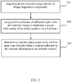
- FIG. 2 is a flowchart of an obstacle identification method in accordance with an embodiment of the present application.
- the method is applied to the self-moving device shown in FIG. 1 and the execution subject of each step is the control component 130 in the self-moving device as an example for description.
- the method includes at least the following steps: step 201: acquiring the environment image sent by the image acquisition component;
- the environment image includes the reflected light obtained by reflecting the line laser emitted by the first line laser emitter by the object.
- a second line laser emitter is also provided on the self-moving device.
- the second line laser emitter is adapted to emit other line laser.
- An emission direction of other line laser is different from an emission direction of line laser.
- the environmental image also includes the reflected light from other line laser reflected by the object. At this time, the environmental image also includes the reflected light from other line laser reflected by the object. step 202: using the pixel coordinates of the reflected light in the environment image to determine the contour information of the object acted on by the line laser;
- the contour information includes but is not limited to the shape and position of the contour.
- the contour information of the object should be flat and smooth; and if there is an obstacle in the moving direction, the contour information of the object is usually uneven. Based on this, the self-moving device is capable of determining whether there is an obstacle in the moving direction through the contour information.
- the self-moving device connects the pixel coordinates of the reflected light so as to obtain the contour information of the object.
- step 203 determining that the object acted on by the line laser is an obstacle, when the contour indicated by the contour information is the contour of an obstacle.
- the self-moving device compares the contour shape in the contour information with the template shape. If the contour shape matches the template shape, the contour indicated by the contour information is an obstacle contour. If the contour shape does not match the template shape, the contour indicated by the contour information is not an obstacle contour.
- the template shape includes contour shapes of each obstacle, such as a contour shape of a carpet; or a contour shape of a step; or a contour shape of a wardrobe etc.
- the number of protrusions in the contour shape is determined by the self-moving device.
- the number of protrusions is greater than a number threshold, it is determined that the contour indicated by the contour information is an obstacle contour.
- the number of protrusions is less than or equal to the number threshold, it is determined that the contour indicated by the contour information is not an obstacle contour.
- the self-moving device may also use other methods to determine whether the contour indicated by the contour information is an obstacle contour, which is not listed here in the present embodiments.
- the self-moving device may also determine a vertical distance of the obstacle relative to the ground according to the contour information.
- determining the vertical distance of the obstacle relative to the ground according to the contour information includes: acquiring a first vertical distance between the ground and the first line laser emitter; determining a second vertical distance between the object acted on by the line laser and the first line laser emitter based on the principle of laser ranging and the pixel coordinates of the contour information; and determining the difference between the second vertical distance and the first vertical distance as the vertical distance.
- the control component is based on the laser ranging principle and the pixel coordinates of the reflected light, a distance between the first line laser emitter and the object can be measured, and the emission angle of the line laser is pre-stored in the self-moving device. Based on the distance between the first line laser emitter and the object, and the emission angle, the second vertical distance between the object and the first line laser emitter can be determined.
- Acquiring the first vertical distance between the ground and the first line laser emitter includes: for historical environmental images collected in history and the vertical distance of the object acted on by the line laser with respect to the ground is less than or equal to a preset distance threshold, based on the principle of laser ranging and the pixel coordinates of the reflected light in the historical environment images, determining a vertical distance between the object and the first line laser emitter so as to obtain the first vertical distance. Since the vertical distance of the object acted on by the line laser relative to the ground is less than or equal to the preset distance threshold, it indicates that the object acted on by the line laser in the historical environment images is not an obstacle. At this time, the object is the earth by default.
- determining the second vertical distance between the object acted on by the line laser and the first line laser emitter includes: determining the vertical distance and the minimum vertical distance between the object acted on by the line laser and the first line laser emitter, based on the principle of laser ranging and the pixel coordinates of the reflected light in the environmental image; and determining the average value between the vertical distance and the minimum vertical distance as the second vertical distance.
- the second vertical distance may also be the vertical distance, and the present embodiment does not limit the arrangement of the second vertical distance.
- the ground information extracted is flat and smooth.
- the first vertical distance H1 of the ground relative to the first line laser emitter can be estimated.
- the second vertical distance H2 of the carpet relative to the first line laser emitter can be estimated.
- the vertical distance of the carpet (H2-H1) can be estimated according to the first vertical distance H1 detected in the moving direction of the self-moving device.
- the self-moving device also includes the second-line laser emitter
- the second-line laser emitter when other line laser emitted by the second line laser emitter hits the carpet, due to the edge characteristics of the carpet, the extracted ground information is irregular with noise data. At this time, the reflected light from other line laser emitted by the carpet assists in determining the vertical distance of the carpet from the self-moving device.
- the obstacle identification method provide by the present application can solve the problem that the existing obstacle identification method is susceptible to the influence of ambient light, resulting in inaccurate identification results.
- the image collection component can still collect the image of the reflected light of the line laser even when the ambient light is dark. Therefore, it can be ensured that obstacles can still be identified even when the ambient light is dark.
- the self-moving device may also determine the work strategy of the self-moving device based on the types of the obstacles. The work strategy is used to avoid or surpass the obstacles.
- determining that the working strategy of the self-moving device is to speed up driving so as to get over the obstacle; when the obstacle is the carpet, and the vertical distance of the carpet with respect to the ground is greater than or equal to the second threshold, determining that the working strategy of the self-moving device is to change the moving direction so as to avoid the obstacle; when the obstacle is a step, the step is below the ground and a maximum vertical distance to the ground is greater than a third threshold and less than a fourth threshold, determining that the working strategy of the self-moving device is to drive at a reduced speed so as to lower to a height corresponding to the step; and when the obstacle is the step, the step is below the ground and the maximum vertical distance to the ground is greater than or equal to the fourth threshold, determining that the working strategy of the self-moving device is to change the moving direction so as to avoid the obstacle.
- the second threshold is greater than the first threshold, and the present embodiment does not limit the value of the first threshold and the value of the second threshold.
- the fourth threshold is greater than the third threshold, and the present embodiment does not limit the value of the third threshold and the value of the fourth threshold.
- FIG. 4 is a block diagram of an obstacle identification apparatus in accordance with an embodiment of the present application.
- the apparatus is applied to the self-moving device shown in FIG. 1 as an example for description.
- the apparatus includes at least the following modules: an image acquisition module 410, a contour determination module 420, and an object identification module 430.
- the image acquisition module 410 is adapted to acquire the environment image sent by the image acquisition component.
- the contour determination module 420 is adapted to use the pixel coordinates of the reflected light in the environment images to determine the contour information of the object acted on by the line laser.
- the object identification module 430 is adapted to determine that the object acted on by the line laser is an obstacle when the contour indicated by the contour information is an obstacle contour.
- the obstacle identification apparatus provided in the foregoing embodiment performs obstacle identification
- only the division of the foregoing functional modules is used for illustration.
- the above-mentioned functions can be allocated by different functional modules as required. That is, the internal structure of the obstacle identification apparatus is divided into different functional modules in order to complete all or part of the functions described above.
- the embodiment of the obstacle identification apparatus and the embodiment of the obstacle identification method belong to the same concept, and the specific implementation processes have been described in detail in the method embodiment, which will not be repeated here.
- FIG. 5 is a block diagram of an obstacle identification apparatus in accordance with an embodiment of the present application.
- the apparatus may be a self-moving device as shown in FIG. 1 .
- the apparatus at least includes a processor 501 and a memory 502.
- the processor 501 may include one or more processing cores, such as a 4-core processor, an 8-core processor etc.
- the processor 501 may be implemented in at least one hardware form among DSP (Digital Signal Processing), FPGA (Field-Programmable Gate Array), and PLA (Programmable Logic Array).
- the processor 501 may also include a main processor and a coprocessor.
- the main processor is a processor used to process data in the awake state, which is also called a CPU (Central Processing Unit).
- the coprocessor is a low-power processor used to process data in the standby state.
- the processor 501 may be integrated with a GPU (Graphics Processing Unit).
- the GPU is used to render and draw the content that needs to be displayed on the display screen.
- the processor 501 may further include an AI (Artificial Intelligence) processor.
- the AI processor is used to process computing operations related to machine learning.
- the memory 502 may include one or more computer-readable storage media.
- the computer-readable storage medium may be non-transitory.
- the memory 502 may also include a high-speed random access memory and a non-volatile memory, such as one or more magnetic disk storage devices and flash memory storage devices.
- the non-transitory computer-readable storage medium in the memory 502 is used to store at least one instruction.
- the at least one instruction is used to be executed by the processor 501 to implement the obstacle identification method provided in the method embodiment of the present application.
- the obstacle identification apparatus may alternatively further include: a peripheral device interface and at least one peripheral device.
- the processor 501, the memory 502 and the peripheral device interface may be communicated by a BUS or a signal line.
- Each peripheral device can be communicated with the peripheral device interface through the BUS, the signal line or a circuit board.
- the peripheral device includes but not limited to: a radio frequency circuit, an image capture component, a line laser emitter, an audio circuit, and a power supply etc.
- the obstacle identification apparatus may also include fewer or more components, which is not limited in the present embodiments.
- the present application also provides a computer-readable storage medium.
- the computer-readable storage medium stores a program.
- the program is loaded and executed by the processor to implement the obstacle identification method of the foregoing method embodiment.
- the present application also provides a computer product.
- the computer product includes a computer-readable storage medium.
- the computer-readable storage medium stores a program.
- the program is loaded and executed by the processor to implement the obstacle identification method of the foregoing method embodiment.
Landscapes
- Engineering & Computer Science (AREA)
- Physics & Mathematics (AREA)
- General Physics & Mathematics (AREA)
- Radar, Positioning & Navigation (AREA)
- Remote Sensing (AREA)
- Computer Networks & Wireless Communication (AREA)
- Electromagnetism (AREA)
- Automation & Control Theory (AREA)
- Aviation & Aerospace Engineering (AREA)
- Multimedia (AREA)
- Theoretical Computer Science (AREA)
- Software Systems (AREA)
- Optics & Photonics (AREA)
- Mathematical Physics (AREA)
- Transportation (AREA)
- Mechanical Engineering (AREA)
- Control Of Position, Course, Altitude, Or Attitude Of Moving Bodies (AREA)
- Length Measuring Devices By Optical Means (AREA)
- Image Analysis (AREA)
- Traffic Control Systems (AREA)
Abstract
Description
- The present application relates to an obstacle identification method, an apparatus, a self-moving device and a storage medium, which belongs to a field of computer technology.
- With continuous development of intelligence, self-moving devices (i.e., sweeping robots, smart lawn mowers, etc.) are capable of automatically identifying whether there is any obstacle in front of them so as to adopt obstacle avoidance strategies.
- Obstacle identification methods in the related art include identifying obstacles in images through image identification algorithms.
- However, when identifying the obstacle through the image identification algorithms, if ambient light is weak, the result of the image identification will be affected, which may cause problems where the obstacle cannot be identified.
- The present application provides an obstacle identification method, an apparatus, a self-moving device and a storage medium, which can improve the obstacle identification result.
- In a first aspect, an obstacle identification method of an embodiment of the present application is provided, the obstacle identification method is used in a self-moving device on which a first line laser emitter and an image acquisition component are installed; the first line laser emitter is adapted to emit line laser obliquely and downwardly along a moving direction; the image acquisition component is adapted to collect an environmental image including reflected light obtained by the line laser reflected by an object; the method comprises:
- acquiring the environment image sent by the image acquisition component;
- using pixel coordinates of the reflected light in the environment image to determine contour information of the object acted on by the line laser; and
- determining that the object acted on by the line laser is an obstacle when a contour indicated by the contour information is an obstacle contour.
- In a possible embodiment, after determining that the object acted on by the line laser is the obstacle, the method further comprises:
determining a vertical distance of the obstacle relative to the ground according to the contour information. - In a possible embodiment, determining the vertical distance of the obstacle relative to the ground according to the contour information comprises:
- acquiring a first vertical distance between the ground and the first line laser emitter;
- determining a second vertical distance between the object acted on by the line laser and the first line laser emitter based on a principle of laser ranging and the pixel coordinates of the contour information; and
- determining a difference between the second vertical distance and the first vertical distance as the vertical distance.
- In a possible embodiment, acquiring the first vertical distance between the ground and the first line laser emitter comprises:
for historical environmental images collected in history and the vertical distance of the object acted on by the line laser with respect to the ground is less than or equal to a preset distance threshold, based on the principle of laser ranging and the pixel coordinates of the reflected light in the historical environment images, determining a vertical distance between the object and the first line laser emitter so as to obtain the first vertical distance. - In a possible embodiment, a second line laser emitter is further provided on the self-moving device, the second line laser emitter is used to emit other line laser, an emission direction of the other line laser is different from an emission direction of the line laser, and the environmental image also includes reflected light obtained by reflecting the other line laser by the object.
- In a possible embodiment, after determining that the object acted on by the line laser is the obstacle, the method further comprises:
determining a working strategy of the self-moving device based on a type of the obstacle, and the working strategy is used to avoid or surpass the obstacle. - In a possible embodiment, determining the working strategy of the self-moving device based on the type of the obstacle comprises:
- when the obstacle is a carpet, and a vertical distance of the carpet with respect to the ground is greater than a first threshold and less than a second threshold, determining that the working strategy of the self-moving device is to speed up driving so as to surpass the obstacle;
- when the obstacle is the carpet, and the vertical distance of the carpet with respect to the ground is greater than or equal to the second threshold, determining that the working strategy of the self-moving device is to change the moving direction so as to avoid the obstacle;
- when the obstacle is a step, the step is below the ground and a maximum vertical distance to the ground is greater than a third threshold and less than a fourth threshold, determining that the working strategy of the self-moving device is to drive at a reduced speed so as to lower to a height corresponding to the step; and
- when the obstacle is the step, the step is below the ground and the maximum vertical distance to the ground is greater than or equal to the fourth threshold, determining that the working strategy of the self-moving device is to change the moving direction so as to avoid the obstacle.
- In a possible embodiment, after using pixel coordinates of the reflected light in the environment image to determine the contour information of the object acted on by the line laser, it further includes: determining the number of protrusions of a contour shape in the contour information;
when the number of the protrusions is greater than a number threshold, and when the contour indicated by the contour information is determined as an obstacle contour by using a non-image identification algorithm, it is determined that the object acted by the line laser is an obstacle; and when the number of the protrusions is less than or equal to the number threshold, it is determined that the contour indicated by the contour information is not an obstacle contour. - In a possible embodiment, when the line laser hits a flat ground, a ground information extracted from the environmental image captured by the image acquisition component is flat and smooth; and when the obstacle is a carpet and the line laser hits the carpet, a ground information extracted from the environmental image captured by the image acquisition component is irregular data with noise.
- In a second aspect, an obstacle identification apparatus of an embodiment of the present application is provided, the obstacle identification apparatus is used in a self-moving device on which a first line laser emitter and an image acquisition component are installed; the first line laser emitter is adapted to emit line laser obliquely and downwardly along a moving direction; the image acquisition component is adapted to collect an environmental image including reflected light obtained by the line laser reflected by an object; the apparatus comprises:
- an image acquisition module adapted to acquire the environment image sent by the image acquisition component;
- a contour determination module adapted to use pixel coordinates of the reflected light in the environmental image to determine contour information of the object acted on by the line laser; and
- an object identification module adapted to determine that the object acted on by the line laser is an obstacle when a contour indicated by the contour information is an obstacle contour.
- In a third aspect, an obstacle identification apparatus of an embodiment of the present application is provided, wherein the apparatus comprises a processor and a memory; a program is stored in the memory, and the program is loaded and executed by the processor to realize an obstacle identification method according to the first aspect.
- In a fourth aspect, a computer-readable storage medium of an embodiment of the present application is provided, wherein a program is stored in the storage medium; and wherein when the program is executed by the processor, it is used to implement an obstacle identification method according to the first aspect.
- In a fifth aspect, an embodiment of the present application provides a self-moving device. The self-moving device includes a shell, a first line laser emitter, an image acquisition component and a control component. The first line laser emitter is disposed on the shell, and is adapted to emit line laser obliquely and downwardly along a moving direction. The image acquisition component is adapted to collect an environmental image including reflected light obtained by the line laser reflected by an object. The first line laser emitter and the image acquisition component are respectively connected in communication with the control component. The control component is adapted to:
- acquire the environment image sent by the image acquisition component;
- use pixel coordinates of the reflected light in the environment image to determine contour information of the object acted on by the line laser; and
- determine that the object acted on by the line laser is an obstacle when a contour indicated by the contour information is an obstacle contour.
- In a possible embodiment, the self-moving device further includes a second line laser emitter. The second line laser emitter is adapted to emit another line laser. An emission direction of the another line laser is different from an emission direction of the line laser. The environmental image also includes reflected light obtained by the another line laser reflected by the object.
- Beneficial effects of the present application include: by installing the first line laser emitter and the image acquisition component on the self-moving device; by using the first line laser emitter to emit a line laser obliquely and downwardly along the moving direction; by using the image acquisition component to acquire the environmental image including reflected light obtained by the line laser reflected by the object; by acquiring the environmental image sent by the image acquisition component; by using the pixel coordinates of the reflected light in the environment image to determine the contour information of the object acted on by the line laser; by determining that the object acted on by the line laser is an obstacle when the contour indicated by the contour information is an obstacle contour; the present application can solve the problem that the existing obstacle identification method is susceptible to the influence of ambient light, resulting in inaccurate identification results. Since the first line laser emitter and the image acquisition component are used to jointly realize the collection of the environmental image, the image collection component can still collect the image of the reflected light of the line laser even when the ambient light is dark. Therefore, it can be ensured that obstacles can still be identified even when the ambient light is dark. In addition, by extracting object contour information based on the pixel coordinates of the reflected light of the line laser, and identifying obstacles based on the contour information, instead of using image identification algorithms to identify obstacles, equipment resources consumed when identifying obstacles can be saved.
- The above description is only an overview of the technical solutions of the present application. In order to be able to understand the technical solutions of the present application more clearly and implement them in accordance with the content of the specification, the preferred embodiments of the present application are described in detail below in conjunction with the accompanying drawings.
-
-
FIG. 1 is a schematic structural view of a self-moving device in accordance with an embodiment of the present application; -
FIG. 2 is a flowchart of an obstacle identification method in accordance with an embodiment of the present application; -
FIG. 3 is a schematic view of a scene of identifying obstacles in accordance with an embodiment of the present application; -
FIG. 4 is a block diagram of an obstacle identification apparatus in accordance with an embodiment of the present application; and -
FIG. 5 is a block diagram of an obstacle identification apparatus in accordance with an embodiment of the present application. - Specific embodiments of the present application will be described in further detail below in conjunction with the accompanying drawings and implementations. The following embodiments are used to illustrate the present application, but are not used to limit the scope of the present application.
-
FIG. 1 is a schematic structural view of a self-moving device in accordance with an embodiment of the present application. The self-moving device refers to a device which is movable without human exertion. The self-moving device includes but not limited to a sweeping robot, a smart lawn mower etc., which is not limited by the present application. As shown inFIG. 1 , the self-moving device at least includes a firstline laser emitter 110, animage acquisition component 120 and acontrol component 130. - The first
line laser emitter 110 is disposed on a shell of the self-moving device, and is used to emit line laser obliquely and downwardly along a moving direction. The number of the firstline laser emitter 110 may be one or more, which is not limited by the embodiments of the present application. - An angle extending obliquely and downwardly along the moving direction with respect to a horizontal direction may be 15°, 30°, 45°, etc. The value of the angle in the present embodiments is not limited to the values mentioned above.
- The
image acquisition component 120 is adapted to acquire an environment image including reflected light obtained by the line laser reflected by an object. In a possible embodiment, theimage acquisition component 120 is a camera, a video camera, etc., which is not limited by the embodiments of the present application. - The first
line laser emitter 110 and theimage acquisition component 120 are respectively communicated with thecontrol component 130. Thecontrol component 130 controls the working sequence of the firstline laser emitter 110 and theimage acquisition component 120. In a possible embodiment, thecontrol component 130 controls the firstline laser emitter 110 to start working before theimage acquisition component 120. - In the present application, the
control component 130 is also adapted to: acquire the environment image sent by theimage acquisition component 120; use the pixel coordinates of the reflected light in the environment image to determine the contour information of the object acted on by the line laser; and determining that the object acted on by the line laser is an obstacle when the contour indicated by the contour information is an obstacle contour. - In a possible embodiment, the contour information includes the shape and position of the contour.
- In a possible embodiment, a second
line laser emitter 140 is also provided on the self-moving device. The secondline laser emitter 140 is adapted to emit other line laser. An emission direction of the other line laser is different from an emission direction of the line laser emitted by the firstline laser emitter 110. The environmental image also includes the reflected light of the other line laser reflected by the object. At this time, the reflected light of other line laser can assist the self-moving device to determine whether there is an obstacle. - Since the first line laser emitter and the image acquisition component are used to jointly realize the collection of the environmental image, the image collection component can still collect the image of the reflected light of the line laser even when the ambient light is dark. Therefore, the self-moving device of the present application can be ensured that obstacles can still be identified even when the ambient light is dark.
- In addition, by extracting object contour information based on the pixel coordinates of the reflected light of the line laser, and identifying obstacles based on the contour information, instead of using image identification algorithms to identify obstacles, equipment resources consumed when identifying obstacles can be saved.
-
FIG. 2 is a flowchart of an obstacle identification method in accordance with an embodiment of the present application. In this embodiment, the method is applied to the self-moving device shown inFIG. 1 and the execution subject of each step is thecontrol component 130 in the self-moving device as an example for description. The method includes at least the following steps:
step 201: acquiring the environment image sent by the image acquisition component; - The environment image includes the reflected light obtained by reflecting the line laser emitted by the first line laser emitter by the object.
- In a possible embodiment, a second line laser emitter is also provided on the self-moving device. The second line laser emitter is adapted to emit other line laser. An emission direction of other line laser is different from an emission direction of line laser. The environmental image also includes the reflected light from other line laser reflected by the object. At this time, the environmental image also includes the reflected light from other line laser reflected by the object.
step 202: using the pixel coordinates of the reflected light in the environment image to determine the contour information of the object acted on by the line laser; - The contour information includes but is not limited to the shape and position of the contour.
- If there is no obstacle in the moving direction of the self-moving device, the contour information of the object should be flat and smooth; and if there is an obstacle in the moving direction, the contour information of the object is usually uneven. Based on this, the self-moving device is capable of determining whether there is an obstacle in the moving direction through the contour information.
- In a possible embodiment, the self-moving device connects the pixel coordinates of the reflected light so as to obtain the contour information of the object.
step 203: determining that the object acted on by the line laser is an obstacle, when the contour indicated by the contour information is the contour of an obstacle. - In a possible embodiment, the self-moving device compares the contour shape in the contour information with the template shape. If the contour shape matches the template shape, the contour indicated by the contour information is an obstacle contour. If the contour shape does not match the template shape, the contour indicated by the contour information is not an obstacle contour.
- Among them, the template shape includes contour shapes of each obstacle, such as a contour shape of a carpet; or a contour shape of a step; or a contour shape of a wardrobe etc.
- And/or, the number of protrusions in the contour shape is determined by the self-moving device. When the number of protrusions is greater than a number threshold, it is determined that the contour indicated by the contour information is an obstacle contour. When the number of protrusions is less than or equal to the number threshold, it is determined that the contour indicated by the contour information is not an obstacle contour.
- Of course, the self-moving device may also use other methods to determine whether the contour indicated by the contour information is an obstacle contour, which is not listed here in the present embodiments.
- In a possible embodiment, after determining that the object acted on by the line laser is an obstacle, the self-moving device may also determine a vertical distance of the obstacle relative to the ground according to the contour information.
- In an illustrated embodiment, determining the vertical distance of the obstacle relative to the ground according to the contour information includes: acquiring a first vertical distance between the ground and the first line laser emitter; determining a second vertical distance between the object acted on by the line laser and the first line laser emitter based on the principle of laser ranging and the pixel coordinates of the contour information; and determining the difference between the second vertical distance and the first vertical distance as the vertical distance.
- Since the control component is based on the laser ranging principle and the pixel coordinates of the reflected light, a distance between the first line laser emitter and the object can be measured, and the emission angle of the line laser is pre-stored in the self-moving device. Based on the distance between the first line laser emitter and the object, and the emission angle, the second vertical distance between the object and the first line laser emitter can be determined.
- Acquiring the first vertical distance between the ground and the first line laser emitter includes: for historical environmental images collected in history and the vertical distance of the object acted on by the line laser with respect to the ground is less than or equal to a preset distance threshold, based on the principle of laser ranging and the pixel coordinates of the reflected light in the historical environment images, determining a vertical distance between the object and the first line laser emitter so as to obtain the first vertical distance. Since the vertical distance of the object acted on by the line laser relative to the ground is less than or equal to the preset distance threshold, it indicates that the object acted on by the line laser in the historical environment images is not an obstacle. At this time, the object is the earth by default.
- In a possible embodiment, determining the second vertical distance between the object acted on by the line laser and the first line laser emitter includes: determining the vertical distance and the minimum vertical distance between the object acted on by the line laser and the first line laser emitter, based on the principle of laser ranging and the pixel coordinates of the reflected light in the environmental image; and determining the average value between the vertical distance and the minimum vertical distance as the second vertical distance. Of course, the second vertical distance may also be the vertical distance, and the present embodiment does not limit the arrangement of the second vertical distance.
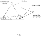
- When the line laser hits a flat ground, in the image captured by the image acquisition component, the ground information extracted is flat and smooth. At this time, the first vertical distance H1 of the ground relative to the first line laser emitter can be estimated.
- Referring to
FIG. 3 , when the line laser hits a carpet, due to the edge characteristics of the carpet, the extracted ground information is irregular data with noise. At this time, the second vertical distance H2 of the carpet relative to the first line laser emitter can be estimated. When the carpet is detected, the vertical distance of the carpet (H2-H1) can be estimated according to the first vertical distance H1 detected in the moving direction of the self-moving device. - When the self-moving device also includes the second-line laser emitter, referring to
FIG. 3 , when other line laser emitted by the second line laser emitter hits the carpet, due to the edge characteristics of the carpet, the extracted ground information is irregular with noise data. At this time, the reflected light from other line laser emitted by the carpet assists in determining the vertical distance of the carpet from the self-moving device. - In summary, by installing the first line laser emitter and the image acquisition component on the self-moving device; by using the first line laser emitter to emit a line laser obliquely and downwardly along the moving direction; by using the image acquisition component to acquire the environmental image including reflected light obtained by the line laser reflected by the object; by acquiring the environmental image sent by the image acquisition component; by using the pixel coordinates of the reflected light in the environment image to determine the contour information of the object acted on by the line laser; by determining that the object acted on by the line laser is an obstacle when the contour indicated by the contour information is an obstacle contour; the obstacle identification method provide by the present application can solve the problem that the existing obstacle identification method is susceptible to the influence of ambient light, resulting in inaccurate identification results. Since the first line laser emitter and the image acquisition component are used to jointly realize the collection of the environmental image, the image collection component can still collect the image of the reflected light of the line laser even when the ambient light is dark. Therefore, it can be ensured that obstacles can still be identified even when the ambient light is dark. In addition, by extracting object contour information based on the pixel coordinates of the reflected light of the line laser, and identifying obstacles based on the contour information, instead of using image identification algorithms to identify obstacles, equipment resources consumed when identifying obstacles can be saved.
- In a possible embodiment, after the
step 203, the self-moving device may also determine the work strategy of the self-moving device based on the types of the obstacles. The work strategy is used to avoid or surpass the obstacles. - In an embodiment, when the obstacle is a carpet, and a vertical distance of the carpet with respect to the ground is greater than a first threshold and less than a second threshold, determining that the working strategy of the self-moving device is to speed up driving so as to get over the obstacle; when the obstacle is the carpet, and the vertical distance of the carpet with respect to the ground is greater than or equal to the second threshold, determining that the working strategy of the self-moving device is to change the moving direction so as to avoid the obstacle; when the obstacle is a step, the step is below the ground and a maximum vertical distance to the ground is greater than a third threshold and less than a fourth threshold, determining that the working strategy of the self-moving device is to drive at a reduced speed so as to lower to a height corresponding to the step; and when the obstacle is the step, the step is below the ground and the maximum vertical distance to the ground is greater than or equal to the fourth threshold, determining that the working strategy of the self-moving device is to change the moving direction so as to avoid the obstacle.
- The second threshold is greater than the first threshold, and the present embodiment does not limit the value of the first threshold and the value of the second threshold.
- The fourth threshold is greater than the third threshold, and the present embodiment does not limit the value of the third threshold and the value of the fourth threshold.
- In this embodiment, by adopting different working strategies based on the different vertical distances of the obstacle relative to the ground, it can be ensured that the self-moving device will not get stuck on the obstacle or fall from a height, thereby affecting the service life of the self-moving device.
-
FIG. 4 is a block diagram of an obstacle identification apparatus in accordance with an embodiment of the present application. In this embodiment, the apparatus is applied to the self-moving device shown inFIG. 1 as an example for description. The apparatus includes at least the following modules: animage acquisition module 410, acontour determination module 420, and anobject identification module 430. - The
image acquisition module 410 is adapted to acquire the environment image sent by the image acquisition component. - The
contour determination module 420 is adapted to use the pixel coordinates of the reflected light in the environment images to determine the contour information of the object acted on by the line laser. - The
object identification module 430 is adapted to determine that the object acted on by the line laser is an obstacle when the contour indicated by the contour information is an obstacle contour. - For related details, refer to the above method embodiment.
- It should be noted that when the obstacle identification apparatus provided in the foregoing embodiment performs obstacle identification, only the division of the foregoing functional modules is used for illustration. In practical applications, the above-mentioned functions can be allocated by different functional modules as required. That is, the internal structure of the obstacle identification apparatus is divided into different functional modules in order to complete all or part of the functions described above. In addition, the embodiment of the obstacle identification apparatus and the embodiment of the obstacle identification method belong to the same concept, and the specific implementation processes have been described in detail in the method embodiment, which will not be repeated here.
-
FIG. 5 is a block diagram of an obstacle identification apparatus in accordance with an embodiment of the present application. The apparatus may be a self-moving device as shown inFIG. 1 . The apparatus at least includes aprocessor 501 and amemory 502. - The
processor 501 may include one or more processing cores, such as a 4-core processor, an 8-core processor etc. Theprocessor 501 may be implemented in at least one hardware form among DSP (Digital Signal Processing), FPGA (Field-Programmable Gate Array), and PLA (Programmable Logic Array). Theprocessor 501 may also include a main processor and a coprocessor. The main processor is a processor used to process data in the awake state, which is also called a CPU (Central Processing Unit). The coprocessor is a low-power processor used to process data in the standby state. In some embodiments, theprocessor 501 may be integrated with a GPU (Graphics Processing Unit). The GPU is used to render and draw the content that needs to be displayed on the display screen. In some embodiments, theprocessor 501 may further include an AI (Artificial Intelligence) processor. The AI processor is used to process computing operations related to machine learning. - The
memory 502 may include one or more computer-readable storage media. The computer-readable storage medium may be non-transitory. Thememory 502 may also include a high-speed random access memory and a non-volatile memory, such as one or more magnetic disk storage devices and flash memory storage devices. In some embodiments, the non-transitory computer-readable storage medium in thememory 502 is used to store at least one instruction. The at least one instruction is used to be executed by theprocessor 501 to implement the obstacle identification method provided in the method embodiment of the present application. - In some embodiments, the obstacle identification apparatus may alternatively further include: a peripheral device interface and at least one peripheral device. The
processor 501, thememory 502 and the peripheral device interface may be communicated by a BUS or a signal line. Each peripheral device can be communicated with the peripheral device interface through the BUS, the signal line or a circuit board. Illustratively, the peripheral device includes but not limited to: a radio frequency circuit, an image capture component, a line laser emitter, an audio circuit, and a power supply etc. - Of course, the obstacle identification apparatus may also include fewer or more components, which is not limited in the present embodiments.
- In a possible embodiment, the present application also provides a computer-readable storage medium. The computer-readable storage medium stores a program. The program is loaded and executed by the processor to implement the obstacle identification method of the foregoing method embodiment.
- In a possible embodiment, the present application also provides a computer product. The computer product includes a computer-readable storage medium. The computer-readable storage medium stores a program. The program is loaded and executed by the processor to implement the obstacle identification method of the foregoing method embodiment.
- The technical features of the above-mentioned embodiments can be combined arbitrarily. In order to make the description concise, not all possible combinations of the various technical features in the foregoing embodiments have been described. However, as long as there is no conflict in combination of these technical features, it should be regarded as the scope described in this specification.
- The above-mentioned embodiments only express several embodiments of the present application, and the description is relatively specific and detailed, but it should not be understood as a limitation on the scope of the present application. It should be pointed out that for those of ordinary skill in the art, without departing from the concept of the present application, several modifications and improvements can be made, and these all fall within the protection scope of the present application. Therefore, the protection scope of the disclosed patent should be subject to the appended claims.
Claims (14)
- An obstacle identification method, the obstacle identification method being used in a self-moving device on which a first line laser emitter and an image acquisition component are installed; the first line laser emitter being adapted to emit line laser obliquely and downwardly along a moving direction; the image acquisition component being adapted to collect an environmental image including reflected light obtained by the line laser reflected by an object; the method comprising:acquiring the environment image sent by the image acquisition component;using pixel coordinates of the reflected light in the environment image to determine contour information of the object acted on by the line laser; anddetermining that the object acted on by the line laser is an obstacle when a contour indicated by the contour information is an obstacle contour.
- The method according to claim 1, wherein after determining that the object acted on by the line laser is the obstacle, the method further comprises:
determining a vertical distance of the obstacle relative to the ground according to the contour information. - The method according to claim 2, wherein determining the vertical distance of the obstacle relative to the ground according to the contour information comprises:acquiring a first vertical distance between the ground and the first line laser emitter;determining a second vertical distance between the object acted on by the line laser and the first line laser emitter based on a principle of laser ranging and the pixel coordinates of the contour information; anddetermining a difference between the second vertical distance and the first vertical distance as the vertical distance.
- The method according to claim 3, wherein acquiring the first vertical distance between the ground and the first line laser emitter comprises:
for historical environmental images collected in history and the vertical distance of the object acted on by the line laser with respect to the ground is less than or equal to a preset distance threshold, based on the principle of laser ranging and the pixel coordinates of the reflected light in the historical environment images, determining a vertical distance between the object and the first line laser emitter so as to obtain the first vertical distance. - The method according to claim 1, wherein a second line laser emitter is further provided on the self-moving device, the second line laser emitter is used to emit other line laser, an emission direction of the other line laser is different from an emission direction of the line laser, and the environmental image also includes reflected light obtained by reflecting the other line laser by the object.
- The method according to any one of claims 1 to 5, wherein after determining that the object acted on by the line laser is the obstacle, the method further comprises:
determining a working strategy of the self-moving device based on a type of the obstacle, and the working strategy is used to avoid or surpass the obstacle. - The method according to claim 6, wherein determining the working strategy of the self-moving device based on the type of the obstacle comprises:when the obstacle is a carpet, and a vertical distance of the carpet with respect to the ground is greater than a first threshold and less than a second threshold, determining that the working strategy of the self-moving device is to speed up driving so as to surpass the obstacle;when the obstacle is the carpet, and the vertical distance of the carpet with respect to the ground is greater than or equal to the second threshold, determining that the working strategy of the self-moving device is to change the moving direction so as to avoid the obstacle;when the obstacle is a step, the step is below the ground and a maximum vertical distance to the ground is greater than a third threshold and less than a fourth threshold, determining that the working strategy of the self-moving device is to drive at a reduced speed so as to lower to a height corresponding to the step; andwhen the obstacle is the step, the step is below the ground and the maximum vertical distance to the ground is greater than or equal to the fourth threshold, determining that the working strategy of the self-moving device is to change the moving direction so as to avoid the obstacle.
- The method according to claim 1, wherein after using pixel coordinates of the reflected light in the environment image to determine the contour information of the object acted on by the line laser, the method further comprises: determining the number of protrusions of a contour shape in the contour information;
when the number of the protrusions is greater than a number threshold, and when the contour indicated by the contour information is determined as an obstacle contour by using a non-image identification algorithm, the method determines that the object acted by the line laser is an obstacle; and when the number of the protrusions is less than or equal to the number threshold, the method determines that the contour indicated by the contour information is not an obstacle contour. - The method according to claim 1, wherein when the line laser hits a flat ground, a ground information extracted from the environmental image captured by the image acquisition component is flat and smooth; and when the obstacle is a carpet and the line laser hits the carpet, a ground information extracted from the environmental image captured by the image acquisition component is irregular data with noise.
- An obstacle identification apparatus, the obstacle identification apparatus being used in a self-moving device on which a first line laser emitter and an image acquisition component are installed; the first line laser emitter being adapted to emit line laser obliquely and downwardly along a moving direction; the image acquisition component being adapted to collect an environmental image including reflected light obtained by the line laser reflected by an object; the apparatus comprising:an image acquisition module adapted to acquire the environment image sent by the image acquisition component;a contour determination module adapted to use pixel coordinates of the reflected light in the environmental image to determine contour information of the object acted on by the line laser; andan object identification module adapted to determine that the object acted on by the line laser is an obstacle when a contour indicated by the contour information is an obstacle contour.
- An obstacle identification apparatus, wherein the obstacle identification apparatus comprises a processor and a memory; a program is stored in the memory, and the program is loaded and executed by the processor to realize an obstacle identification method according to any one of claims 1 to 9.
- A computer-readable storage medium, wherein a program is stored in the storage medium; and wherein when the program is executed by a processor, it is used to implement an obstacle identification method according to any one of claims 1 to 9.
- A self-moving device, comprising: a shell, a first line laser emitter, an image acquisition component and a control component; the first line laser emitter being disposed on the shell, and being adapted to emit line laser obliquely and downwardly along a moving direction; the image acquisition component being adapted to collect an environmental image comprising reflected light obtained by the line laser reflected by an object; the first line laser emitter and the image acquisition component being respectively connected in communication with the control component, the control component being adapted to:acquire the environment image sent by the image acquisition component;use pixel coordinates of the reflected light in the environment image to determine contour information of the object acted on by the line laser; anddetermine that the object acted on by the line laser is an obstacle when a contour indicated by the contour information is an obstacle contour.
- The self-moving device according to claim 13, further comprising a second line laser emitter, the second line laser emitter being adapted to emit another line laser, an emission direction of the another line laser being different from an emission direction of the line laser; the environmental image also comprising reflected light obtained by the another line laser reflected by the object.
Applications Claiming Priority (2)
| Application Number | Priority Date | Filing Date | Title |
|---|---|---|---|
| CN202010322554.9A CN111538034B (en) | 2020-04-22 | 2020-04-22 | Obstacle identification method, device and storage medium |
| PCT/CN2021/076964 WO2021212986A1 (en) | 2020-04-22 | 2021-02-20 | Obstacle identification method and apparatus, self-moving device and storage medium |
Publications (2)
| Publication Number | Publication Date |
|---|---|
| EP4050378A1 true EP4050378A1 (en) | 2022-08-31 |
| EP4050378A4 EP4050378A4 (en) | 2023-05-24 |
Family
ID=71973097
Family Applications (1)
| Application Number | Title | Priority Date | Filing Date |
|---|---|---|---|
| EP21793582.4A Withdrawn EP4050378A4 (en) | 2020-04-22 | 2021-02-20 | OBSTACLE IDENTIFICATION METHOD AND APPARATUS, SELF-PROPELLED DEVICE AND RECORDING MEDIA |
Country Status (6)
| Country | Link |
|---|---|
| US (1) | US20220273152A1 (en) |
| EP (1) | EP4050378A4 (en) |
| JP (1) | JP7383828B2 (en) |
| KR (1) | KR20220086682A (en) |
| CN (3) | CN113189614B (en) |
| WO (1) | WO2021212986A1 (en) |
Families Citing this family (17)
| Publication number | Priority date | Publication date | Assignee | Title |
|---|---|---|---|---|
| CN113189614B (en) * | 2020-04-22 | 2023-08-11 | 追觅创新科技(苏州)有限公司 | Obstacle recognition method, device and storage medium |
| CN111743464A (en) * | 2020-07-06 | 2020-10-09 | 追创科技(苏州)有限公司 | A method and device for obstacle avoidance based on line laser |
| CN112417944B (en) * | 2020-08-31 | 2024-04-16 | 深圳银星智能集团股份有限公司 | Robot control method and electronic device |
| CN114445440B (en) * | 2020-11-03 | 2025-05-13 | 苏州科瓴精密机械科技有限公司 | Obstacle recognition method for self-propelled equipment and self-propelled equipment |
| CN114617476A (en) * | 2021-06-02 | 2022-06-14 | 北京石头创新科技有限公司 | Self-moving equipment |
| CN115877831B (en) * | 2021-09-29 | 2026-04-07 | 上海富伸光电有限公司 | Motion control method for a self-propelled device and the self-propelled device |
| CN113848943B (en) * | 2021-10-18 | 2023-08-08 | 追觅创新科技(苏州)有限公司 | Grid map correction method and device, storage medium and electronic device |
| CN116069004A (en) * | 2021-10-29 | 2023-05-05 | 追觅创新科技(苏州)有限公司 | Self-moving device, method and medium for determining obstacle edge of self-moving device |
| CN116087986B (en) * | 2021-11-08 | 2025-11-14 | 追觅创新科技(苏州)有限公司 | Self-moving devices, obstacle detection methods for self-moving devices, and storage media |
| CN113989650B (en) * | 2021-11-25 | 2025-03-18 | 深圳市优象计算技术有限公司 | A carpet recognition method based on laser reflection characteristics |
| CN114815821B (en) * | 2022-04-19 | 2022-12-09 | 山东亚历山大智能科技有限公司 | Indoor self-adaptive panoramic obstacle avoidance method and system based on multi-line laser radar |
| CN117630957A (en) * | 2022-08-16 | 2024-03-01 | 追觅创新科技(苏州)有限公司 | Object distance detection method and device, storage medium and electronic device |
| CN118151641A (en) * | 2022-12-02 | 2024-06-07 | 北京石头世纪科技股份有限公司 | Obstacle avoidance module, robot, control method, obstacle avoidance method and related device |
| CN118259659A (en) * | 2022-12-23 | 2024-06-28 | 速感科技(北京)有限公司 | Autonomous mobile device, obstacle detection method thereof, and computer readable medium |
| CN117008594A (en) * | 2022-12-30 | 2023-11-07 | 北京石头创新科技有限公司 | Obstacle avoidance method and device, equipment and medium for self-propelled equipment based on line laser |
| CN117048596B (en) * | 2023-08-04 | 2024-05-10 | 广州汽车集团股份有限公司 | Obstacle avoidance method, device, vehicle and storage medium |
| CN118235999A (en) * | 2024-04-18 | 2024-06-25 | 追觅创新科技(苏州)有限公司 | Travel control method of cleaning robot, cleaning robot and storage medium |
Family Cites Families (33)
| Publication number | Priority date | Publication date | Assignee | Title |
|---|---|---|---|---|
| GB9203448D0 (en) * | 1992-02-18 | 1992-04-01 | British Steel Plc | Shape detection |
| US7079943B2 (en) * | 2003-10-07 | 2006-07-18 | Deere & Company | Point-to-point path planning |
| JP2006146778A (en) | 2004-11-24 | 2006-06-08 | Konica Minolta Photo Imaging Inc | Head mount display device |
| JP4241651B2 (en) * | 2005-03-16 | 2009-03-18 | パナソニック電工株式会社 | Mobile device |
| CN101227539B (en) * | 2007-01-18 | 2010-09-29 | 联想移动通信科技有限公司 | Blind-guiding mobile phone and blind-guiding method |
| JP2011060113A (en) * | 2009-09-11 | 2011-03-24 | Mitsubishi Fuso Truck & Bus Corp | Collision avoidance support device for vehicle |
| JP5372680B2 (en) | 2009-09-24 | 2013-12-18 | 日立オートモティブシステムズ株式会社 | Obstacle detection device |
| CN102495672A (en) * | 2011-10-20 | 2012-06-13 | 广州市迪拓信息科技有限公司 | Position judging method in touch control |
| JP6132659B2 (en) * | 2013-02-27 | 2017-05-24 | シャープ株式会社 | Ambient environment recognition device, autonomous mobile system using the same, and ambient environment recognition method |
| JP5862623B2 (en) * | 2013-08-08 | 2016-02-16 | カシオ計算機株式会社 | Image processing apparatus, image processing method, and program |
| US11176655B2 (en) * | 2014-01-27 | 2021-11-16 | Cognex Corporation | System and method for determining 3D surface features and irregularities on an object |
| JP2017535279A (en) * | 2014-09-23 | 2017-11-30 | 宝時得科技(中国)有限公司Positec Technology (China) Co.,Ltd. | Automatic mobile robot |
| JP2016211852A (en) * | 2015-04-28 | 2016-12-15 | 一般財団法人電力中央研究所 | Method for measuring surface unevenness and measurement apparatus |
| KR101762504B1 (en) * | 2015-08-31 | 2017-07-28 | 고려대학교 산학협력단 | Method for detecting floor obstacle using laser range finder |
| JP6677516B2 (en) * | 2016-01-21 | 2020-04-08 | シャープ株式会社 | Autonomous traveling device |
| CN108008411A (en) * | 2016-10-31 | 2018-05-08 | 张舒怡 | A kind of sensor for automatic Pilot |
| KR20220025250A (en) | 2017-06-02 | 2022-03-03 | 에이비 엘렉트로룩스 | Method of detecting a difference in level of a surface in front of a robotic cleaning device |
| CN107632308B (en) * | 2017-08-24 | 2021-02-05 | 吉林大学 | Method for detecting contour of obstacle in front of vehicle based on recursive superposition algorithm |
| CN107589625B (en) * | 2017-09-30 | 2020-05-29 | 歌尔科技有限公司 | Automatic zooming method of projector and projector |
| CN109753982B (en) * | 2017-11-07 | 2021-09-03 | 北京京东乾石科技有限公司 | Obstacle point detection method, obstacle point detection device, and computer-readable storage medium |
| CN108444390B (en) * | 2018-02-08 | 2021-01-26 | 天津大学 | Unmanned automobile obstacle identification method and device |
| CN109166125B (en) * | 2018-07-06 | 2021-03-12 | 长安大学 | Three-dimensional depth image segmentation algorithm based on multi-edge fusion mechanism |
| CN113961005A (en) * | 2018-10-22 | 2022-01-21 | 科沃斯机器人股份有限公司 | Travel control method, surface cleaning robot, and storage medium |
| CN209803009U (en) * | 2018-10-30 | 2019-12-17 | 四川晴测科技有限公司 | Pavement crack detection device |
| CN109357091B (en) * | 2018-12-18 | 2024-04-26 | 广东福斯特流体技术有限公司 | A pipeline component connection structure and connection method |
| CN109350018B (en) * | 2019-01-08 | 2019-04-26 | 湖南超能机器人技术有限公司 | The palm detection method based on image applied to palm bleb detection system |
| CN109782807B (en) * | 2019-03-08 | 2021-10-01 | 哈尔滨工程大学 | An AUV Obstacle Avoidance Method in the Environment of Revolving Obstacles |
| CN110298853B (en) * | 2019-07-04 | 2021-05-25 | 易思维(杭州)科技有限公司 | Visual inspection method for surface difference |
| CN110353583A (en) * | 2019-08-21 | 2019-10-22 | 追创科技(苏州)有限公司 | Sweeping robot and automatic control method thereof |
| CN110928301B (en) * | 2019-11-19 | 2023-06-30 | 北京小米智能科技有限公司 | Method, device and medium for detecting tiny obstacle |
| CN110928315A (en) * | 2019-12-20 | 2020-03-27 | 深圳市杉川机器人有限公司 | Autonomous robot and its control method |
| CN110989631B (en) * | 2019-12-30 | 2022-07-12 | 科沃斯机器人股份有限公司 | Self-moving robot control method, device, self-moving robot and storage medium |
| CN113189614B (en) * | 2020-04-22 | 2023-08-11 | 追觅创新科技(苏州)有限公司 | Obstacle recognition method, device and storage medium |
-
2020
- 2020-04-22 CN CN202110398861.XA patent/CN113189614B/en active Active
- 2020-04-22 CN CN202110390797.0A patent/CN113296117B/en active Active
- 2020-04-22 CN CN202010322554.9A patent/CN111538034B/en active Active
-
2021
- 2021-02-20 JP JP2022541668A patent/JP7383828B2/en active Active
- 2021-02-20 WO PCT/CN2021/076964 patent/WO2021212986A1/en not_active Ceased
- 2021-02-20 KR KR1020227018029A patent/KR20220086682A/en not_active Withdrawn
- 2021-02-20 EP EP21793582.4A patent/EP4050378A4/en not_active Withdrawn
-
2022
- 2022-05-18 US US17/747,957 patent/US20220273152A1/en not_active Abandoned
Also Published As
| Publication number | Publication date |
|---|---|
| WO2021212986A1 (en) | 2021-10-28 |
| EP4050378A4 (en) | 2023-05-24 |
| US20220273152A1 (en) | 2022-09-01 |
| JP2023500994A (en) | 2023-01-17 |
| JP7383828B2 (en) | 2023-11-20 |
| CN113189614B (en) | 2023-08-11 |
| CN111538034B (en) | 2021-05-28 |
| KR20220086682A (en) | 2022-06-23 |
| CN113296117B (en) | 2023-08-08 |
| CN113189614A (en) | 2021-07-30 |
| CN111538034A (en) | 2020-08-14 |
| CN113296117A (en) | 2021-08-24 |
Similar Documents
| Publication | Publication Date | Title |
|---|---|---|
| US20220273152A1 (en) | Obstacle identification method, apparatus, self-moving device and storage medium | |
| US12197223B2 (en) | Intelligent obstacle avoidance method and apparatus based on binocular vision, and non-transitory computer-readable storage medium | |
| CN111932943B (en) | Dynamic target detection method and device, storage medium and roadbed monitoring equipment | |
| CN114387585B (en) | Obstacle detection method, detection device, and travel device | |
| EP3974778B1 (en) | Method and apparatus for updating working map of mobile robot, and storage medium | |
| CN112171675B (en) | Obstacle avoidance method and device for mobile robot, robot and storage medium | |
| EP4184278A1 (en) | Automatic recharging method and apparatus, storage medium, charging base, and system | |
| CN109840454B (en) | Target positioning method, device, storage medium and equipment | |
| CN117746318A (en) | Intelligent bird repelling method and system for offshore wind farm | |
| WO2023045749A1 (en) | Charging device, self-moving device, charging method and system, and storage medium | |
| CA3221167A1 (en) | Self-moving device | |
| CN120496027A (en) | Obstacle recognition method and related equipment | |
| CN112200130A (en) | Three-dimensional target detection method and device and terminal equipment | |
| CN116580300A (en) | A method for identifying obstacles, a mobile device and a storage medium | |
| US20240057492A1 (en) | Obstacle Recognition Method, Apparatus, Device, Medium and Weeding Robot | |
| CN116486130A (en) | Obstacle recognition method, device, mobile device and storage medium | |
| US20220284707A1 (en) | Target detection and control method, system, apparatus and storage medium | |
| CN119826836B (en) | Robot with body, obstacle avoidance control method, device and program product thereof | |
| JP2020052772A (en) | Image processing device, image processing program, and image processing system | |
| US20240296674A1 (en) | Obstacle Recognition Method and Apparatus, Device, Medium and Weeding Robot | |
| CN121259720A (en) | Obstacle detection method, obstacle detection device, robot, and computer-readable storage medium | |
| CN116310835A (en) | Target area identification method and device, electronic equipment, storage medium | |
| CN116385395A (en) | Self-mobile device recharge control method, device and storage medium | |
| CN120198880A (en) | Lane line information determination method, lane line information determination device, lane line information determination medium, lane line information determination program product and vehicle | |
| CN121921754A (en) | Near-field obstacle recognition method, near-field image recognition and transmission method |
Legal Events
| Date | Code | Title | Description |
|---|---|---|---|
| STAA | Information on the status of an ep patent application or granted ep patent |
Free format text: STATUS: THE INTERNATIONAL PUBLICATION HAS BEEN MADE |
|
| PUAI | Public reference made under article 153(3) epc to a published international application that has entered the european phase |
Free format text: ORIGINAL CODE: 0009012 |
|
| STAA | Information on the status of an ep patent application or granted ep patent |
Free format text: STATUS: REQUEST FOR EXAMINATION WAS MADE |
|
| 17P | Request for examination filed |
Effective date: 20220525 |
|
| AK | Designated contracting states |
Kind code of ref document: A1 Designated state(s): AL AT BE BG CH CY CZ DE DK EE ES FI FR GB GR HR HU IE IS IT LI LT LU LV MC MK MT NL NO PL PT RO RS SE SI SK SM TR |
|
| A4 | Supplementary search report drawn up and despatched |
Effective date: 20230424 |
|
| RIC1 | Information provided on ipc code assigned before grant |
Ipc: G01S 7/481 20060101ALI20230418BHEP Ipc: G06V 20/10 20220101ALI20230418BHEP Ipc: G06V 10/60 20220101ALI20230418BHEP Ipc: G06V 20/58 20220101ALI20230418BHEP Ipc: G01S 17/42 20060101ALI20230418BHEP Ipc: G01S 7/48 20060101ALI20230418BHEP Ipc: G01S 17/88 20060101ALI20230418BHEP Ipc: G01S 17/931 20200101AFI20230418BHEP |
|
| DAV | Request for validation of the european patent (deleted) | ||
| DAX | Request for extension of the european patent (deleted) | ||
| STAA | Information on the status of an ep patent application or granted ep patent |
Free format text: STATUS: THE APPLICATION IS DEEMED TO BE WITHDRAWN |
|
| 18D | Application deemed to be withdrawn |
Effective date: 20231123 |