EP4050203B1 - Pitch control method and apparatus based on clearance of wind turbine - Google Patents
Pitch control method and apparatus based on clearance of wind turbine Download PDFInfo
- Publication number
- EP4050203B1 EP4050203B1 EP20878613.7A EP20878613A EP4050203B1 EP 4050203 B1 EP4050203 B1 EP 4050203B1 EP 20878613 A EP20878613 A EP 20878613A EP 4050203 B1 EP4050203 B1 EP 4050203B1
- Authority
- EP
- European Patent Office
- Prior art keywords
- clearance
- pitch angle
- wind turbine
- additional
- interval
- Prior art date
- Legal status (The legal status is an assumption and is not a legal conclusion. Google has not performed a legal analysis and makes no representation as to the accuracy of the status listed.)
- Active
Links
Images




Classifications
-
- F—MECHANICAL ENGINEERING; LIGHTING; HEATING; WEAPONS; BLASTING
- F03—MACHINES OR ENGINES FOR LIQUIDS; WIND, SPRING, OR WEIGHT MOTORS; PRODUCING MECHANICAL POWER OR A REACTIVE PROPULSIVE THRUST, NOT OTHERWISE PROVIDED FOR
- F03D—WIND MOTORS
- F03D7/00—Controlling wind motors
- F03D7/02—Controlling wind motors the wind motors having rotation axis substantially parallel to the air flow entering the rotor
- F03D7/022—Adjusting aerodynamic properties of the blades
- F03D7/0224—Adjusting blade pitch
-
- F—MECHANICAL ENGINEERING; LIGHTING; HEATING; WEAPONS; BLASTING
- F03—MACHINES OR ENGINES FOR LIQUIDS; WIND, SPRING, OR WEIGHT MOTORS; PRODUCING MECHANICAL POWER OR A REACTIVE PROPULSIVE THRUST, NOT OTHERWISE PROVIDED FOR
- F03D—WIND MOTORS
- F03D17/00—Monitoring or testing of wind motors, e.g. diagnostics
-
- F—MECHANICAL ENGINEERING; LIGHTING; HEATING; WEAPONS; BLASTING
- F03—MACHINES OR ENGINES FOR LIQUIDS; WIND, SPRING, OR WEIGHT MOTORS; PRODUCING MECHANICAL POWER OR A REACTIVE PROPULSIVE THRUST, NOT OTHERWISE PROVIDED FOR
- F03D—WIND MOTORS
- F03D7/00—Controlling wind motors
- F03D7/02—Controlling wind motors the wind motors having rotation axis substantially parallel to the air flow entering the rotor
- F03D7/022—Adjusting aerodynamic properties of the blades
- F03D7/024—Adjusting aerodynamic properties of the blades of individual blades
-
- F—MECHANICAL ENGINEERING; LIGHTING; HEATING; WEAPONS; BLASTING
- F05—INDEXING SCHEMES RELATING TO ENGINES OR PUMPS IN VARIOUS SUBCLASSES OF CLASSES F01-F04
- F05B—INDEXING SCHEME RELATING TO WIND, SPRING, WEIGHT, INERTIA OR LIKE MOTORS, TO MACHINES OR ENGINES FOR LIQUIDS COVERED BY SUBCLASSES F03B, F03D AND F03G
- F05B2270/00—Control
- F05B2270/10—Purpose of the control system
- F05B2270/17—Purpose of the control system to avoid excessive deflection of the blades
-
- F—MECHANICAL ENGINEERING; LIGHTING; HEATING; WEAPONS; BLASTING
- F05—INDEXING SCHEMES RELATING TO ENGINES OR PUMPS IN VARIOUS SUBCLASSES OF CLASSES F01-F04
- F05B—INDEXING SCHEME RELATING TO WIND, SPRING, WEIGHT, INERTIA OR LIKE MOTORS, TO MACHINES OR ENGINES FOR LIQUIDS COVERED BY SUBCLASSES F03B, F03D AND F03G
- F05B2270/00—Control
- F05B2270/30—Control parameters, e.g. input parameters
- F05B2270/328—Blade pitch angle
-
- F—MECHANICAL ENGINEERING; LIGHTING; HEATING; WEAPONS; BLASTING
- F05—INDEXING SCHEMES RELATING TO ENGINES OR PUMPS IN VARIOUS SUBCLASSES OF CLASSES F01-F04
- F05B—INDEXING SCHEME RELATING TO WIND, SPRING, WEIGHT, INERTIA OR LIKE MOTORS, TO MACHINES OR ENGINES FOR LIQUIDS COVERED BY SUBCLASSES F03B, F03D AND F03G
- F05B2270/00—Control
- F05B2270/30—Control parameters, e.g. input parameters
- F05B2270/329—Azimuth or yaw angle
-
- F—MECHANICAL ENGINEERING; LIGHTING; HEATING; WEAPONS; BLASTING
- F05—INDEXING SCHEMES RELATING TO ENGINES OR PUMPS IN VARIOUS SUBCLASSES OF CLASSES F01-F04
- F05B—INDEXING SCHEME RELATING TO WIND, SPRING, WEIGHT, INERTIA OR LIKE MOTORS, TO MACHINES OR ENGINES FOR LIQUIDS COVERED BY SUBCLASSES F03B, F03D AND F03G
- F05B2270/00—Control
- F05B2270/30—Control parameters, e.g. input parameters
- F05B2270/33—Proximity of blade to tower
-
- Y—GENERAL TAGGING OF NEW TECHNOLOGICAL DEVELOPMENTS; GENERAL TAGGING OF CROSS-SECTIONAL TECHNOLOGIES SPANNING OVER SEVERAL SECTIONS OF THE IPC; TECHNICAL SUBJECTS COVERED BY FORMER USPC CROSS-REFERENCE ART COLLECTIONS [XRACs] AND DIGESTS
- Y02—TECHNOLOGIES OR APPLICATIONS FOR MITIGATION OR ADAPTATION AGAINST CLIMATE CHANGE
- Y02E—REDUCTION OF GREENHOUSE GAS [GHG] EMISSIONS, RELATED TO ENERGY GENERATION, TRANSMISSION OR DISTRIBUTION
- Y02E10/00—Energy generation through renewable energy sources
- Y02E10/70—Wind energy
- Y02E10/72—Wind turbines with rotation axis in wind direction
Definitions
- the present disclosure generally relates to the technical field of wind power generation, and more particularly, to a pitch control method and device based on a clearance of a wind turbine.
- Clearance is a key design indicator in the development of a wind turbine, especially with the development of large rotors and lightweight glass fiber blades, blades become quite soft, and the clearance is facing quite a severe challenge.
- an intelligent sensing technology has been applied in the clearance monitoring.
- the clearance is improved to a certain extent and the safety of a unit is improved.
- An existing protection scheme based on measurement of the clearance is to protect a next blade through pitch control on a single blade according to the clearance measurement of a current blade, so as to prevent the next blade from "sweeping the tower".
- the pitch control scheme for a single blade has the risk of rotor imbalance, and the existing pitch control scheme for a single blade is open-loop, which does not form a closed-loop feedback protection based on the clearance.
- US 2014/ 0 294 584 A1 discloses a method of operating a wind turbine.
- the instantaneous representative wind speed and the distance between the tower and one of the blades are determined.
- a tower distance pitch adjustment is determined based on the determined distance, and the one or more pitch systems applies the determined tower distance pitch adjustment to at least a next blade to be in the shadow of the tower.
- EP 2 726 735 B1 discloses a method for controlling a wind turbine, in particular a method for controlling pitch of one or more blades of a wind turbine and related system.
- the method comprises collecting first data indicative of a dynamic condition of the first wind turbine blade and the rotor, the first data comprising rotor data and first deflection data, the rotor data being indicative of the azimuth position and rotational velocity of the rotor in a rotor plane perpendicular to the rotor axis, and the first deflection data being indicative of the position, speed and acceleration of one or more parts of the first wind turbine blade.
- the method comprises calculating an expected tower clearance distance at a later time of tower passage for the first wind turbine blade based on the first data including acceleration of one or more parts of the first wind turbine blade, and performing measures to prevent tower collision, if the expected tower clearance distance fulfills a collision risk criterion.
- An object of an embodiment of the present disclosure is to provide a pitch control method and device based on a clearance of a wind turbine, so as to overcome at least one of the above disadvantages.
- the invention is set out in the appended set of claims.
- FIG. 1 is a flowchart of a pitch control method based on a clearance of a wind turbine according to an embodiment of the present disclosure.
- a clearance of the wind turbine is obtained in real time.
- the wind turbine includes at least two blades. In some embodiments, the wind turbine may include three blades.
- the clearance refers to a distance from a blade tip to a tower surface during rotation of a rotor, and constraints for clearance are defined in the IEC standard: L S ⁇ P CT ⁇ ⁇ M ⁇ ⁇ ⁇ ⁇ L S
- L S is a static clearance
- ⁇ M is a material safety factor
- ⁇ f is a load safety factor
- P CT is a required value of a dynamic clearance
- various existing detection devices may be used to detect the clearance of the wind turbine in real time, such that the clearance of the wind turbine can be obtained from the detection device in real time.
- various detection devices may include a senor for measuring the clearance.
- the pitch control method based on the clearance of the wind turbine may further include: performing failure detection on the sensor. For example, it may be determined whether the sensor fails by detecting an available state of the sensor.
- the available state of the sensor may be determined based on a heartbeat signal of the sensor and an algorithm accuracy flag of the sensor.
- the sensor is considered to be not failed if it is determined that the sensor is in the available state currently, and the clearance of the wind turbine may be obtained from the sensor at this time.
- the sensor is considered to be failed if it is determined that the sensor is in an unavailable state currently, and at this time, data detected by the sensor is unusable, and a signal indicating the sensor fails is reported for timely maintenance.
- a pitch control function based on the clearance before performing failure detection on the sensor, it may be further determined whether a pitch control function based on the clearance is enabled.
- the failure detection is performed on the sensor if the pitch control function is in an enabled state. If the pitch control function is not in the enabled state, it is continuously determined whether the pitch control function based on the clearance is enabled. As an example, it may be determined whether the pitch control function is enabled by detecting an enable flag for indicating the pitch control function based on the clearance.
- the pitch control method based on the clearance of the wind turbine may further include: determining a current rotor azimuth.
- the step S 10 is performed to obtain the clearance of the wind turbine if the rotor azimuth indicates that the blade is located within an effective azimuth range for measuring the clearance.
- a method for detecting the clearance of the wind turbine is described with reference to FIG. 2 . It should be understood that the method for detecting the clearance shown in FIG. 2 is merely an example. The present disclosure is not limited thereto, and other methods may also be used to detect the clearance.
- FIG. 2 is a schematic view of a clearance monitoring system according to an embodiment of the present disclosure.
- FIG. 2 is a schematic view showing an installation of the clearance monitoring system for detecting the clearance of the wind turbine.
- 101 is a collection apparatus of the clearance monitoring system.
- the collection apparatus may be arranged at a bottom of a nacelle of the wind turbine, and the collection apparatus detects and calculates the clearance in real time when the blade rotates to the lowest point.
- 102 is an azimuth sensor for detecting the rotor azimuth.
- 103 is a control system of the wind turbine.
- the control system 103 obtains the clearance from the collection apparatus 101 in real time, and obtains the rotor azimuth from the azimuth sensor in real time, so as to perform pitch control.
- a device with light weight, high precision (preferably, within 0.1m), high reliability, strong environmental adaptability, and high sampling frequency may be selected as the collection apparatus of the clearance monitoring system of the tower.
- the collection apparatus may obtain an image including the blades and the tower, and analyze the image to determine the clearance of the tower.
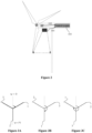
- FIGS. 3A to 3C are schematic views of measuring the rotor azimuth according to an embodiment of the present disclosure.
- the rotor azimuth ⁇ (rotor azimuth) records a position of the rotor.
- effective azimuth ranges for measuring the clearance may be defined as PI 3 ⁇ ⁇ , PI 3 + ⁇ , [ PI- ⁇ , PI + ⁇ ], and 5 ⁇ PI 3 ⁇ ⁇ , 5 ⁇ PI 3 + ⁇ , respectively.
- PI 180deg
- ⁇ is an angle range for outputting effective measured clearance.
- Different clearance detection methods may have different effective azimuth ranges for measuring the clearance.
- step S20 an additional pitch angle value of each blade is dynamically adjusted according to the clearance obtained in real time.
- a correspondence between multiple clearance intervals and multiple adjustments of the additional pitch angle may be established in advance.
- a clearance interval corresponding to the clearance obtained in real time may be determined, and the additional pitch angle value of each blade may be dynamically adjusted based on the adjustment of the additional pitch angle corresponding to the clearance interval corresponding to the clearance.
- Steps of dynamically adjusting the additional pitch angle value of each blade will be described with reference to FIG. 4 hereinafter.
- FIG. 4 is a flowchart of steps of dynamically adjusting the additional pitch angle value of each blade according to an embodiment of the present disclosure. It should be understood that the method of dynamically adjusting the additional pitch angle value of each blade shown in FIG. 4 is merely an example. The present disclosure is not limited thereto, and other methods may also be used to dynamically adjust the additional pitch angle value of each blade based on the clearance.
- step S201 a clearance interval corresponding to the clearance obtained in real time is determined.
- the clearance of the wind turbine After the clearance of the wind turbine is obtained, it may be determined, based on preset clearance intervals, the obtained clearance belongs to which clearance interval of the preset clearance intervals.
- step S202 the additional pitch angle value of each blade is dynamically adjusted according to the determined clearance interval. If the determined clearance interval is a first clearance interval (that is, the clearance is less than a clearance safety threshold), a shutdown protection function for clearance over-limit is triggered and the wind turbine is controlled to shut down. If the determined clearance interval is a second clearance interval (that is, the clearance is greater than or equal to the clearance safety threshold), an additional pitch angle protection function is triggered and the additional pitch angle value of each blade is dynamically adjusted.
- a first clearance interval that is, the clearance is less than a clearance safety threshold
- a shutdown protection function for clearance over-limit is triggered and the wind turbine is controlled to shut down.
- the determined clearance interval is a second clearance interval (that is, the clearance is greater than or equal to the clearance safety threshold)
- an additional pitch angle protection function is triggered and the additional pitch angle value of each blade is dynamically adjusted.
- the clearance interval corresponding to the clearance obtained in real time is the first clearance interval, it indicates that the wind turbine currently has a large risk of "sweeping the tower" and the wind turbine may be controlled to shut down at this time. For example, the wind turbine may be controlled to quickly shut down.
- the clearance protection is realized by controlling the wind turbine to shut down in a case that the clearance obtained in real time is within the first clearance interval, and the clearance protection is realized by adjusting the additional pitch angle value in a case that the clearance obtained in real time is within the second clearance interval.
- the additional pitch angle value is adjusted on a basis of an original pitch angle given value, to reduce an ability of the wind turbine in absorbing wind energy, such that the clearance increases.
- the clearance is monitored in real time, and the additional pitch angle value is further dynamically adjusted based on the change of the clearance obtained in real time, to ensure that the clearance is within a safe range, thereby forming a closed-loop pitch control strategy based on the clearance.
- the additional pitch angle value is gradually increased within a first preset time, to reach a preset additional angle value.
- the process of gradually increasing the additional pitch angle value may refer to increasing the additional pitch angle value in each calculation period to reach the preset additional angle value.
- the above method of gradually increasing the additional pitch angle value can increase the additional pitch angle to the preset additional angle value within a short time.
- the preset additional angle value may refer to an additional pitch angle value that can keep the blade being within a safe clearance range, and the preset additional angle value may be determined based on the boost demand for the clearance and the responsiveness of a pitch actuator determined based on a current wind condition.
- the additional pitch angle value may be increased at a uniform speed in each calculation period. For example, taking the preset additional angle value of 2 degrees as an example, the additional pitch angle value may be increased by 2 degrees at a uniform speed within 1 second.
- maintaining the current additional pitch angle value invariant refers to maintaining an additional pitch angle value of a previous calculation period invariant. Namely, when the clearance interval corresponding to the clearance changes from the second clearance interval to the third clearance interval, the additional pitch angle value at this time is maintained invariant.
- the change of the clearance mainly depends on the change of a current wind speed. If the wind speed gradually decreases, the clearance may further increase. If the clearance interval corresponding to the clearance obtained in real time changes from the third clearance interval to a fourth clearance interval, it indicates that the clearance is excessively large, which may cause unnecessary loss of power generation. Therefore, the additional pitch angle value needs to be reduced to gradually decrease the clearance, and moreover, the ability of the wind turbine in absorbing the wind energy needs to be increased. Specifically, the current additional pitch angle value may be gradually decreased within a second preset time.
- a time length of the second preset time may be set to be greater than a time length of the first preset time, so that the additional pitch angle value is gradually decreased.
- the process of gradually decreasing the additional pitch angle value may refer to decreasing the additional pitch angle value in each calculation period.
- the additional pitch angle value may be decreased at a uniform speed in each calculation period. If the clearance interval corresponding to the clearance obtained in real time changes from the fourth clearance interval to the third clearance interval, the additional pitch angle value is continuously decreased until the second preset time expires. If the clearance interval corresponding to the clearance obtained in real time changes from the third clearance interval to the second clearance interval before the second preset time expires, the additional pitch angle value restarts to be increased gradually within the first preset time to reach the preset additional angle value.
- the additional pitch angle protection function is triggered in a case that the clearance obtained in real time is within the second clearance interval. If the clearance obtained in real time is determined to be within the third clearance interval or the fourth clearance interval before the additional pitch angle protection function is triggered, no additional intervention is required since there is no additional pitch angle value, and the wind turbine may be controlled to execute a conventional control strategy at this time.
- three thresholds for clearance protection are set, and the three thresholds include a first threshold, a second threshold and a third threshold.
- a clearance safety threshold for triggering shutdown of the wind turbine is determined as the first threshold
- a clearance threshold for triggering the additional pitch angle protection is determined as the second threshold
- a clearance threshold for triggering a reset of the additional pitch angle protection is determined as the third threshold.
- the third threshold is greater than the second threshold
- the second threshold is greater than the first threshold.
- clearance intervals i.e., the first clearance interval, the second clearance interval, the third clearance interval and the fourth clearance interval, may be obtained based on the three thresholds set above.
- a zero value serves as a lower limit of the first clearance interval
- the first threshold serves as an upper limit of the first clearance interval
- the first clearance interval is a half-closed and half-open interval.
- the first threshold serves as a lower limit of the second clearance interval
- the second threshold serves as an upper limit of the second clearance interval
- the second clearance interval is a half-closed and half-open interval.
- the second threshold serves as a lower limit of the third clearance interval
- the third threshold serves as an upper limit of the third clearance interval
- the third clearance interval is a half-closed and half-open interval.
- the third threshold serves as a lower limit of the fourth clearance interval
- the fourth clearance interval is a half-closed and half-open interval.
- An upper limit of the fourth clearance interval may refer to a theoretical maximum value of clearance determined according to the actual working condition of the wind turbine.
- a pitch angle control value of each blade is determined according to an existing pitch angle given value and the additional pitch angle value of each blade.
- the pitch angle control value of each blade is the sum of the existing pitch angle given value and the additional pitch angle value of the blade in the calculation period.
- the pitch angle given value may refer to an existing pitch angle given value under the conventional pitch strategy. That is, the additional pitch angle protection function according to the embodiment of the present disclosure is to add a pitch angle value on a basis of the conventional pitch strategy, so as to adjust the clearance.
- the additional pitch angle value may be gradually increased from zero to the preset additional angle value.
- the additional pitch angle value may be gradually decreased to zero.
- step S40 each blade is controlled to perform a pitch action based on the determined pitch angle control value, to adjust the clearance of the wind turbine.
- the determined pitch angle control value is applied to the corresponding blade, to control all blades to perform a pitch action simultaneously, which can effectively avoid the risk of rotor imbalance in the existing pitch control scheme for single blade.
- the pitch control method based on the clearance of the wind turbine may further include the following operations. If it is determined that a complete additional pitch angle protection has been completed once, the additional pitch angle protection function is stopped to avoid frequent triggering of this function, and timing is started. During the timing, the shutdown protection function for clearance over-limit is kept to be enabled, to ensure the safe operation of the wind turbine.
- the additional pitch angle protection function is re-enabled. As an example, it may be determined that the complete additional pitch angle protection has been completed once when the following condition is met: the additional pitch angle value increases from zero, and decreases to zero within the second preset time.
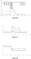
- FIGS. 5A to 5D are schematic views showing control effects of the above pitch control method under an extreme wind shear working condition according to an embodiment of the present disclosure.
- FIGS. 5A to 5D show simulation results under DLC1.5 working condition based on IEC standard.
- FIG. 5A shows the change of the wind speed at a rotor surface when the extreme vertical wind shear occurs, with time on abscissa and wind speed value on the ordinate. A difference in wind speed between the top of the rotor surface and the bottom of the rotor surface leads to a rapid reduction of the clearance.
- the dashed line indicates the wind speed at the top of the rotor surface
- the solid line indicates the wind speed at the bottom of the rotor surface.
- the abscissa is time
- the solid line represents the clearance interval where the clearance obtained in time is located
- the dashed line indicates the real-time change of the additional pitch angel value
- the dotted line indicates the change of the enable flag of the additional pitch angle protection function. It indicates that the additional pitch angle protection function is in an enabled state in a case that the enable flag is 1, and it indicates that the additional pitch angle protection function is not in the enabled state in a case that the enable flag is 0.
- the additional pitch angle value is controlled to gradually increase, so as to gradually increase the clearance; when the clearance is increased to be within the fourth clearance interval, the additional pitch angle value is controlled to gradually decrease.
- the additional pitch angle value needs to be gradually increased again, until the bad wind condition is over and the clearance is in a safe state. After the complete clearance protection control cycle has been completed once, the enable flag is changed to a low level, and the additional pitch angle protection function is not allowed to be triggered again within the preset time.
- the abscissa is time and the ordinate is the pitch angle value.
- the dashed line indicates the pitch angle value of the blade when the additional pitch angle protection function is turned on, and the solid line indicates the pitch angle value of the blade when the additional pitch angle protection function is not turned on. It can be seen from FIG. 5C that the pitch angle value of the blade when the additional pitch angle protection function is turned on is increased relative to the pitch angle value of the blade when the additional pitch angle protection function is not turned on.
- the abscissa is time and the ordinate is the minimum clearance value.
- the dashed line indicates the minimum clearance value when the additional pitch angle protection function is turned on, and the solid line indicates the minimum clearance value when the additional pitch angle protection function is not turned on. It can be seen from FIG. 5D that the minimum clearance value when the additional pitch angle protection function is turned on is significantly boosted relative to the minimum clearance when the additional pitch angle protection function is not turned on.
- FIGS. 6A to 6E are schematic views showing control effects of the above pitch control method under a normal power generation working condition according to an embodiment of the present disclosure.
- FIGS. 6A to 6E show simulation results under DLC1.2 working condition based on IEC standard.
- a trigger mechanism under the normal power generation working condition is the same with that under the above extreme wind shear working condition, and the pitch control method based on the embodiment of the present disclosure can boost the clearance to a certain extent.
- FIG. 6A is a wind speed variation curve of normal turbulence, with time on the abscissa and wind speed value on the ordinate.
- the abscissa is time
- the solid line represents the clearance interval where the clearance obtained in real time is located
- the dashed line represents the real-time change of the additional pitch angle value
- the dotted line represents the change of the enable flag of the additional pitch angle protection function.
- the abscissa is time and the ordinate is the pitch angle value.
- the dashed line indicates the pitch angle value of the blade when the additional pitch angle protection function is turned on, and the solid line indicates the pitch angle value of the blade when the additional pitch angle protection function is not turned on. It can be seen from FIG. 6C that the pitch angle value of the blade when the additional pitch angle protection function is turned on is increased relative to the pitch angle value of the blade when the additional pitch angle protection function is not turned on.
- the abscissa is time and the ordinate is the minimum clearance value.
- the dashed line indicates the minimum clearance value when the additional pitch angle protection function is turned on, and the solid line indicates the minimum clearance value when the additional pitch angle protection function is not turned on. It can be seen from FIG. 6D that the minimum clearance value when the additional pitch angle protection function is turned on is boosted relative to the minimum clearance value when the additional pitch angle protection function is not turned on.
- the abscissa is time and the ordinate is the on-grid power. It can be seen from FIG. 6E that triggering the additional pitch angle protection function under the normal power generation working condition may lead to small loss of power generation.
- FIG. 7 is a block diagram of a pitch control device based on a clearance of a wind turbine according to an embodiment of the present disclosure.
- the pitch control device 100 based on the clearance of the wind turbine according to the embodiment of the present disclosure includes: a clearance acquisition module 101, an additional pitch angle adjustment module 102, a pitch angle control value determination module 103 and a pitch control module 104.
- the wind turbine includes at least two blades. In some embodiments, the wind turbine may include three blades.
- the clearance acquisition module 101 is configured to obtain the clearance of the wind turbine in real time.
- the pitch control device based on the clearance of the wind turbine may further include: an azimuth determination module (not shown in the figure).
- the azimuth determination module is configured to determine a current rotor azimuth. When the rotor azimuth indicates that the blade is located within an effective azimuth range for measuring the clearance, the clearance acquisition module obtains the clearance of the wind turbine.
- various existing detection devices may be used to detect the clearance of the wind turbine in real time, and the clearance acquisition module 101 obtains the clearance of the wind turbine from the detection device in real time.
- the various detection devices may include a sensor for measuring the clearance.
- the pitch control device based on the clearance of the wind turbine according to the embodiment of the present disclosure may further include: a failure detection module (not shown in the figure).
- the failure detection module is configured to perform failure detection on the sensor.
- the failure detection module may determine whether the sensor fails by detecting an available state of the sensor.
- the available state of the sensor may be determined based on a heartbeat signal of the sensor and an algorithm accuracy flag of the sensor.
- the sensor is considered to not fail when the failure detection module determines that the sensor is currently in the available state, and the clearance acquisition module 101 may obtain the clearance of the wind turbine from the sensor at this time.
- the sensor is considered to fail when the failure detection module determines that the sensor is currently in an unavailable state, and data detected by the sensor is unusable at this time.
- the pitch control module immediately controls the wind turbine to switch to other clearance protection strategy. A signal indicating the sensor fails is reported for timely maintenance of the failed sensor.
- the failure detection module may further determine whether the pitch control function based on the clearance according to the embodiment of the present disclosure is enabled.
- the failure detection module performs failure detection on the senor when the pitch control function is in an enabled state.
- the failure detection module continuously determines whether the pitch control function based on the clearance is enabled.
- the failure detection module may determine whether the pitch control function is enabled by detecting an enable flag for indicating the pitch control function based on the clearance.
- the additional pitch angle adjustment module 102 is configured to dynamically adjust an additional pitch angle value of each blade based on the clearance obtained in real time.
- the additional pitch angle adjustment module 102 may determine a clearance interval corresponding to the clearance obtained in real time, and dynamically adjust the additional pitch angle value of each blade based on an adjustment of the additional pitch angle corresponding to the clearance interval corresponding to the clearance.
- FIG. 8 is a block diagram of a controller of a wind turbine according to an embodiment of the present disclosure.
- the controller 200 of the wind turbine includes: a processor 201, an input/output interface 202, and a memory 203.
- the memory 203 is configured to store a computer program.
- the computer program when executed by the processor 201 implements the pitch control method based on the clearance of the wind turbine described above.
- the input/output interface 202 is configured to connect various input/output devices.
- the controller 200 of the wind turbine may be a main controller arranged in the wind turbine or a sub controller interacting with the main controller.
- modules shown in FIG. 7 may be implemented by a general-purpose hardware processor such as a digital signal processor or a field programmable gate array, or by a dedicated hardware processor such as a dedicated chip, or by software entirely through a computer program.
- modules shown in FIG. 7 may be implemented as modules in the processor 201 shown in FIG. 8 .
- FIG. 9 is a block diagram of a control system of a wind turbine according to an embodiment of the present disclosure.
- control system 300 of the wind turbine includes: a sensor 301 and a controller 302.
- the sensor 301 is configured to detect a clearance of the wind turbine in real time.
- the sensor 301 herein may be any existing device that is able to detect the clearance of the wind turbine.
- the sensor 301 may include, but is not limited to, a range sensor (such as a multi-layer laser range finder).
- the controller 302 is configured to obtain the clearance of the wind turbine from the sensor 301 in real time, to perform the pitch control method based on the clearance of the wind turbine described above.
- the pitch control method based on the clearance of the wind turbine shown in FIG. 1 is performed in the controller 302, which will not be repeated herein.
- a computer-readable storage medium storing a computer program is further provided according to an embodiment of the present disclosure.
- the computer-readable storage medium stores the computer program, which when executed by a processor causes the processor to perform the above pitch control method based on the clearance of the wind turbine.
- the computer-readable storage medium may be any data storage device that can store data read by a computer system. Examples of the computer-readable storage medium include: read only memory, random access memory, CD-ROM, magnetic tape, floppy disk, optical data storage device, and carrier wave (such as data transmissions through the Internet via a wired or wireless transmission path).
- the pitch control method and device based on the clearance of the wind turbine can realize the closed-loop feedback control based on the clearance measured in real time, and improve the clearance with more safety and effectiveness.
- the pitch control method and device based on the clearance of the wind turbine according to the embodiments of the present disclosure further can reduce the loss of power generation while ensuring the clearance safety.
- the pitch control method and device based on the clearance of the wind turbine according to the embodiments of the present disclosure have a short algorithm development cycle and a low calculation cost.
- the clearance problem of the soft blade can be solved and the cost of the blade can be effectively reduced by using the pitch control method and device based on the clearance of the wind turbine according to the embodiments of the present disclosure.
Landscapes
- Engineering & Computer Science (AREA)
- Life Sciences & Earth Sciences (AREA)
- Sustainable Development (AREA)
- Sustainable Energy (AREA)
- Chemical & Material Sciences (AREA)
- Combustion & Propulsion (AREA)
- Mechanical Engineering (AREA)
- General Engineering & Computer Science (AREA)
- Physics & Mathematics (AREA)
- Fluid Mechanics (AREA)
- Wind Motors (AREA)
- Turbine Rotor Nozzle Sealing (AREA)
Description
- The present disclosure generally relates to the technical field of wind power generation, and more particularly, to a pitch control method and device based on a clearance of a wind turbine.
- Clearance is a key design indicator in the development of a wind turbine, especially with the development of large rotors and lightweight glass fiber blades, blades become quite soft, and the clearance is facing quite a severe challenge.
- At present, an intelligent sensing technology has been applied in the clearance monitoring. By detecting the clearance in real time and timely activating a protection measure in case of risk, the clearance is improved to a certain extent and the safety of a unit is improved. An existing protection scheme based on measurement of the clearance is to protect a next blade through pitch control on a single blade according to the clearance measurement of a current blade, so as to prevent the next blade from "sweeping the tower". However, the pitch control scheme for a single blade has the risk of rotor imbalance, and the existing pitch control scheme for a single blade is open-loop, which does not form a closed-loop feedback protection based on the clearance.
-
US 2014/ 0 294 584 A1 discloses a method of operating a wind turbine. In the method, the instantaneous representative wind speed and the distance between the tower and one of the blades are determined. A tower distance pitch adjustment is determined based on the determined distance, and the one or more pitch systems applies the determined tower distance pitch adjustment to at least a next blade to be in the shadow of the tower. -
EP 2 726 735 B1 - An object of an embodiment of the present disclosure is to provide a pitch control method and device based on a clearance of a wind turbine, so as to overcome at least one of the above disadvantages. The invention is set out in the appended set of claims.
-
-
FIG. 1 is a flowchart of a pitch control method based on a clearance of a wind turbine according to an embodiment of the present disclosure; -
FIG. 2 is a schematic view of a clearance monitoring system according to an embodiment of the present disclosure; -
FIGS. 3A to 3C are schematic views of measuring a rotor azimuth according to an embodiment of the present disclosure; -
FIG. 4 is a flowchart of steps of dynamically adjusting an additional pitch angle value of each blade according to an embodiment of the present disclosure; -
FIGS. 5A to 5D are schematic views showing control effects of the above pitch control method under an extreme wind shear working condition according to an embodiment of the present disclosure; -
FIGS. 6A to 6E are schematic views showing control effects of the above pitch control method under a normal power generation working condition according to an embodiment of the present disclosure; -
FIG. 7 is a block diagram of a pitch control device based on a clearance of a wind turbine according to an embodiment of the present disclosure; -
FIG. 8 is a block diagram of a controller of a wind turbine according to an embodiment of the present disclosure; and -
FIG. 9 is a block diagram of a control system of a wind turbine according to an embodiment of the present disclosure. - Different exemplary embodiments will be described fully with reference to the drawings. Some embodiments are shown in the drawings.
-
FIG. 1 is a flowchart of a pitch control method based on a clearance of a wind turbine according to an embodiment of the present disclosure. - Referring to
FIG. 1 , in step S10, a clearance of the wind turbine is obtained in real time. The wind turbine includes at least two blades. In some embodiments, the wind turbine may include three blades. - According to an embodiment of the present disclosure, the clearance refers to a distance from a blade tip to a tower surface during rotation of a rotor, and constraints for clearance are defined in the IEC standard:

- In formula (1), LS is a static clearance, γM is a material safety factor, γf is a load safety factor, and PCT is a required value of a dynamic clearance.
- Various existing detection devices may be used to detect the clearance of the wind turbine in real time, such that the clearance of the wind turbine can be obtained from the detection device in real time. For example, various detection devices may include a senor for measuring the clearance.
- In some embodiments, before performing
step S 10, the pitch control method based on the clearance of the wind turbine may further include: performing failure detection on the sensor. For example, it may be determined whether the sensor fails by detecting an available state of the sensor. The available state of the sensor may be determined based on a heartbeat signal of the sensor and an algorithm accuracy flag of the sensor. The sensor is considered to be not failed if it is determined that the sensor is in the available state currently, and the clearance of the wind turbine may be obtained from the sensor at this time. The sensor is considered to be failed if it is determined that the sensor is in an unavailable state currently, and at this time, data detected by the sensor is unusable, and a signal indicating the sensor fails is reported for timely maintenance. - In some embodiments, before performing failure detection on the sensor, it may be further determined whether a pitch control function based on the clearance is enabled. The failure detection is performed on the sensor if the pitch control function is in an enabled state. If the pitch control function is not in the enabled state, it is continuously determined whether the pitch control function based on the clearance is enabled. As an example, it may be determined whether the pitch control function is enabled by detecting an enable flag for indicating the pitch control function based on the clearance.
- In some embodiments, before performing the
step S 10, the pitch control method based on the clearance of the wind turbine may further include: determining a current rotor azimuth. Thestep S 10 is performed to obtain the clearance of the wind turbine if the rotor azimuth indicates that the blade is located within an effective azimuth range for measuring the clearance. - A method for detecting the clearance of the wind turbine is described with reference to
FIG. 2 . It should be understood that the method for detecting the clearance shown inFIG. 2 is merely an example. The present disclosure is not limited thereto, and other methods may also be used to detect the clearance. -
FIG. 2 is a schematic view of a clearance monitoring system according to an embodiment of the present disclosure. -
FIG. 2 is a schematic view showing an installation of the clearance monitoring system for detecting the clearance of the wind turbine. As shown inFIG. 2 , 101 is a collection apparatus of the clearance monitoring system. The collection apparatus may be arranged at a bottom of a nacelle of the wind turbine, and the collection apparatus detects and calculates the clearance in real time when the blade rotates to the lowest point. 102 is an azimuth sensor for detecting the rotor azimuth. 103 is a control system of the wind turbine. Thecontrol system 103 obtains the clearance from thecollection apparatus 101 in real time, and obtains the rotor azimuth from the azimuth sensor in real time, so as to perform pitch control. - As an example, a device with light weight, high precision (preferably, within 0.1m), high reliability, strong environmental adaptability, and high sampling frequency may be selected as the collection apparatus of the clearance monitoring system of the tower. The collection apparatus may obtain an image including the blades and the tower, and analyze the image to determine the clearance of the tower.
-
FIGS. 3A to 3C are schematic views of measuring the rotor azimuth according to an embodiment of the present disclosure. - As shown in
FIGS. 3A to 3C , taking the wind turbine with three blades as an example, a first blade, a second blade and a third blade of the wind turbine are supposed to rotate in a clockwise direction. The rotor azimuth ψ (rotor azimuth) records a position of the rotor. The rotor azimuth is 0 degree (ψ=0deg) when the first blade is vertically upward, and ψ=180deg when the first blade is at the lowest position. - As an example, in an embodiment of the present disclosure, effective azimuth ranges for measuring the clearance may be defined as


- Returning to
FIG. 1 , in step S20, an additional pitch angle value of each blade is dynamically adjusted according to the clearance obtained in real time. - In some embodiments, a correspondence between multiple clearance intervals and multiple adjustments of the additional pitch angle may be established in advance. In this case, a clearance interval corresponding to the clearance obtained in real time may be determined, and the additional pitch angle value of each blade may be dynamically adjusted based on the adjustment of the additional pitch angle corresponding to the clearance interval corresponding to the clearance.
- Steps of dynamically adjusting the additional pitch angle value of each blade will be described with reference to
FIG. 4 hereinafter. -
FIG. 4 is a flowchart of steps of dynamically adjusting the additional pitch angle value of each blade according to an embodiment of the present disclosure. It should be understood that the method of dynamically adjusting the additional pitch angle value of each blade shown inFIG. 4 is merely an example. The present disclosure is not limited thereto, and other methods may also be used to dynamically adjust the additional pitch angle value of each blade based on the clearance. - Referring to
FIG. 4 , in step S201, a clearance interval corresponding to the clearance obtained in real time is determined. - After the clearance of the wind turbine is obtained, it may be determined, based on preset clearance intervals, the obtained clearance belongs to which clearance interval of the preset clearance intervals.
- In step S202, the additional pitch angle value of each blade is dynamically adjusted according to the determined clearance interval. If the determined clearance interval is a first clearance interval (that is, the clearance is less than a clearance safety threshold), a shutdown protection function for clearance over-limit is triggered and the wind turbine is controlled to shut down. If the determined clearance interval is a second clearance interval (that is, the clearance is greater than or equal to the clearance safety threshold), an additional pitch angle protection function is triggered and the additional pitch angle value of each blade is dynamically adjusted.
- When the clearance interval corresponding to the clearance obtained in real time is the first clearance interval, it indicates that the wind turbine currently has a large risk of "sweeping the tower" and the wind turbine may be controlled to shut down at this time. For example, the wind turbine may be controlled to quickly shut down.
- In other words, the clearance protection is realized by controlling the wind turbine to shut down in a case that the clearance obtained in real time is within the first clearance interval, and the clearance protection is realized by adjusting the additional pitch angle value in a case that the clearance obtained in real time is within the second clearance interval.
- In some embodiments, after the additional pitch angle protection function is triggered, the additional pitch angle value is adjusted on a basis of an original pitch angle given value, to reduce an ability of the wind turbine in absorbing wind energy, such that the clearance increases. At the same time, the clearance is monitored in real time, and the additional pitch angle value is further dynamically adjusted based on the change of the clearance obtained in real time, to ensure that the clearance is within a safe range, thereby forming a closed-loop pitch control strategy based on the clearance.
- The specific process of dynamically adjusting the additional pitch angle value of each blade after the additional pitch angle protection function is triggered will be described below.
- When the clearance interval corresponding to the clearance obtained in real time is the second clearance interval, it indicates that the clearance of the wind turbine is smaller and needs to be intervened through pitch control. Therefore, the additional pitch angle value is gradually increased within a first preset time, to reach a preset additional angle value.
- As an example, the process of gradually increasing the additional pitch angle value may refer to increasing the additional pitch angle value in each calculation period to reach the preset additional angle value. The above method of gradually increasing the additional pitch angle value can increase the additional pitch angle to the preset additional angle value within a short time. Herein, the preset additional angle value may refer to an additional pitch angle value that can keep the blade being within a safe clearance range, and the preset additional angle value may be determined based on the boost demand for the clearance and the responsiveness of a pitch actuator determined based on a current wind condition.
- In some embodiments, the additional pitch angle value may be increased at a uniform speed in each calculation period. For example, taking the preset additional angle value of 2 degrees as an example, the additional pitch angle value may be increased by 2 degrees at a uniform speed within 1 second.
- In the process of gradually increasing the additional pitch angle value or after the additional pitch angle value reaches the preset additional angle value, if the clearance interval corresponding to the clearance obtained in real time changes from the second clearance interval to a third clearance interval, a current additional pitch angle value is maintained invariant. At this time, it indicates that the clearance has been already in a safe clearance range by the above adjustment of the additional pitch angle.
- Herein, maintaining the current additional pitch angle value invariant refers to maintaining an additional pitch angle value of a previous calculation period invariant. Namely, when the clearance interval corresponding to the clearance changes from the second clearance interval to the third clearance interval, the additional pitch angle value at this time is maintained invariant.
- In a case that the additional pitch angle is invariant, the change of the clearance mainly depends on the change of a current wind speed. If the wind speed gradually decreases, the clearance may further increase. If the clearance interval corresponding to the clearance obtained in real time changes from the third clearance interval to a fourth clearance interval, it indicates that the clearance is excessively large, which may cause unnecessary loss of power generation. Therefore, the additional pitch angle value needs to be reduced to gradually decrease the clearance, and moreover, the ability of the wind turbine in absorbing the wind energy needs to be increased. Specifically, the current additional pitch angle value may be gradually decreased within a second preset time. As an example, in order to prevent the load caused by the wind energy absorption by the wind turbine from being increased too quickly in the process of reducing the pitch angle, a time length of the second preset time may be set to be greater than a time length of the first preset time, so that the additional pitch angle value is gradually decreased.
- As an example, the process of gradually decreasing the additional pitch angle value may refer to decreasing the additional pitch angle value in each calculation period. In some embodiments, the additional pitch angle value may be decreased at a uniform speed in each calculation period. If the clearance interval corresponding to the clearance obtained in real time changes from the fourth clearance interval to the third clearance interval, the additional pitch angle value is continuously decreased until the second preset time expires. If the clearance interval corresponding to the clearance obtained in real time changes from the third clearance interval to the second clearance interval before the second preset time expires, the additional pitch angle value restarts to be increased gradually within the first preset time to reach the preset additional angle value.
- It should be understood that in an embodiment of the present disclosure, the additional pitch angle protection function is triggered in a case that the clearance obtained in real time is within the second clearance interval. If the clearance obtained in real time is determined to be within the third clearance interval or the fourth clearance interval before the additional pitch angle protection function is triggered, no additional intervention is required since there is no additional pitch angle value, and the wind turbine may be controlled to execute a conventional control strategy at this time.
- In an embodiment of the present disclosure, three thresholds for clearance protection are set, and the three thresholds include a first threshold, a second threshold and a third threshold. A clearance safety threshold for triggering shutdown of the wind turbine is determined as the first threshold, a clearance threshold for triggering the additional pitch angle protection is determined as the second threshold, and a clearance threshold for triggering a reset of the additional pitch angle protection is determined as the third threshold. The third threshold is greater than the second threshold, and the second threshold is greater than the first threshold.
- Four clearance intervals, i.e., the first clearance interval, the second clearance interval, the third clearance interval and the fourth clearance interval, may be obtained based on the three thresholds set above.
- Firstly, a zero value serves as a lower limit of the first clearance interval, the first threshold serves as an upper limit of the first clearance interval, and the first clearance interval is a half-closed and half-open interval. The first threshold serves as a lower limit of the second clearance interval, the second threshold serves as an upper limit of the second clearance interval, and the second clearance interval is a half-closed and half-open interval. The second threshold serves as a lower limit of the third clearance interval, the third threshold serves as an upper limit of the third clearance interval, and the third clearance interval is a half-closed and half-open interval. The third threshold serves as a lower limit of the fourth clearance interval, and the fourth clearance interval is a half-closed and half-open interval. An upper limit of the fourth clearance interval may refer to a theoretical maximum value of clearance determined according to the actual working condition of the wind turbine.
- Returning to
FIG. 1 , in step S30, a pitch angle control value of each blade is determined according to an existing pitch angle given value and the additional pitch angle value of each blade. - Within each calculation period, the pitch angle control value of each blade is the sum of the existing pitch angle given value and the additional pitch angle value of the blade in the calculation period. The pitch angle given value may refer to an existing pitch angle given value under the conventional pitch strategy. That is, the additional pitch angle protection function according to the embodiment of the present disclosure is to add a pitch angle value on a basis of the conventional pitch strategy, so as to adjust the clearance.
- In the case of gradually increasing the additional pitch angle value, the additional pitch angle value may be gradually increased from zero to the preset additional angle value. In the case of gradually decreasing the additional pitch angle value, the additional pitch angle value may be gradually decreased to zero.
- In step S40, each blade is controlled to perform a pitch action based on the determined pitch angle control value, to adjust the clearance of the wind turbine.
- In some embodiments, simultaneously for each blade of the wind turbine, the determined pitch angle control value is applied to the corresponding blade, to control all blades to perform a pitch action simultaneously, which can effectively avoid the risk of rotor imbalance in the existing pitch control scheme for single blade.
- In some embodiments of the present disclosure, it may also be included a protection function for avoiding frequent triggering of the additional pitch angle protection function.
- In order to avoid the increase of pitch fatigue caused by frequently switching between the increase and the decrease of the additional pitch angle value due to frequent triggering of the pitch control function based on the clearance, the additional pitch angle protection function will no longer be triggered within a preset time after a complete additional pitch angle protection has been completed once. Therefore, the pitch control method based on the clearance of the wind turbine according to the embodiment of the present disclosure may further include the following operations. If it is determined that a complete additional pitch angle protection has been completed once, the additional pitch angle protection function is stopped to avoid frequent triggering of this function, and timing is started. During the timing, the shutdown protection function for clearance over-limit is kept to be enabled, to ensure the safe operation of the wind turbine. When the timing has reached a preset time, the additional pitch angle protection function is re-enabled. As an example, it may be determined that the complete additional pitch angle protection has been completed once when the following condition is met: the additional pitch angle value increases from zero, and decreases to zero within the second preset time.
-
FIGS. 5A to 5D are schematic views showing control effects of the above pitch control method under an extreme wind shear working condition according to an embodiment of the present disclosure. -
FIGS. 5A to 5D show simulation results under DLC1.5 working condition based on IEC standard.FIG. 5A shows the change of the wind speed at a rotor surface when the extreme vertical wind shear occurs, with time on abscissa and wind speed value on the ordinate. A difference in wind speed between the top of the rotor surface and the bottom of the rotor surface leads to a rapid reduction of the clearance. InFIG. 5A , the dashed line indicates the wind speed at the top of the rotor surface, and the solid line indicates the wind speed at the bottom of the rotor surface. - As shown in
FIG. 5B , the abscissa is time, the solid line represents the clearance interval where the clearance obtained in time is located, the dashed line indicates the real-time change of the additional pitch angel value, and the dotted line indicates the change of the enable flag of the additional pitch angle protection function. It indicates that the additional pitch angle protection function is in an enabled state in a case that the enable flag is 1, and it indicates that the additional pitch angle protection function is not in the enabled state in a case that the enable flag is 0. - Taking
FIG. 5B as an example, when the extreme vertical wind shear comes, if the clearance is decreased to be within the second clearance interval, the additional pitch angle value is controlled to gradually increase, so as to gradually increase the clearance; when the clearance is increased to be within the fourth clearance interval, the additional pitch angle value is controlled to gradually decrease. In the process of gradually decreasing the additional pitch angle value, if the clearance is decreased to be within the second clearance interval again, it indicates that the bad wind condition has not been over yet, the additional pitch angle value needs to be gradually increased again, until the bad wind condition is over and the clearance is in a safe state. After the complete clearance protection control cycle has been completed once, the enable flag is changed to a low level, and the additional pitch angle protection function is not allowed to be triggered again within the preset time. - As shown in
FIG. 5C , the abscissa is time and the ordinate is the pitch angle value. The dashed line indicates the pitch angle value of the blade when the additional pitch angle protection function is turned on, and the solid line indicates the pitch angle value of the blade when the additional pitch angle protection function is not turned on. It can be seen fromFIG. 5C that the pitch angle value of the blade when the additional pitch angle protection function is turned on is increased relative to the pitch angle value of the blade when the additional pitch angle protection function is not turned on. - As shown in
FIG. 5D , the abscissa is time and the ordinate is the minimum clearance value. The dashed line indicates the minimum clearance value when the additional pitch angle protection function is turned on, and the solid line indicates the minimum clearance value when the additional pitch angle protection function is not turned on. It can be seen fromFIG. 5D that the minimum clearance value when the additional pitch angle protection function is turned on is significantly boosted relative to the minimum clearance when the additional pitch angle protection function is not turned on. -
FIGS. 6A to 6E are schematic views showing control effects of the above pitch control method under a normal power generation working condition according to an embodiment of the present disclosure. -
FIGS. 6A to 6E show simulation results under DLC1.2 working condition based on IEC standard. A trigger mechanism under the normal power generation working condition is the same with that under the above extreme wind shear working condition, and the pitch control method based on the embodiment of the present disclosure can boost the clearance to a certain extent. -
FIG. 6A is a wind speed variation curve of normal turbulence, with time on the abscissa and wind speed value on the ordinate. As shown inFIG. 6B , the abscissa is time, the solid line represents the clearance interval where the clearance obtained in real time is located, the dashed line represents the real-time change of the additional pitch angle value, and the dotted line represents the change of the enable flag of the additional pitch angle protection function. - As shown in
FIG. 6C , the abscissa is time and the ordinate is the pitch angle value. The dashed line indicates the pitch angle value of the blade when the additional pitch angle protection function is turned on, and the solid line indicates the pitch angle value of the blade when the additional pitch angle protection function is not turned on. It can be seen fromFIG. 6C that the pitch angle value of the blade when the additional pitch angle protection function is turned on is increased relative to the pitch angle value of the blade when the additional pitch angle protection function is not turned on. - As shown in
FIG. 6D , the abscissa is time and the ordinate is the minimum clearance value. The dashed line indicates the minimum clearance value when the additional pitch angle protection function is turned on, and the solid line indicates the minimum clearance value when the additional pitch angle protection function is not turned on. It can be seen fromFIG. 6D that the minimum clearance value when the additional pitch angle protection function is turned on is boosted relative to the minimum clearance value when the additional pitch angle protection function is not turned on. - As shown in
FIG. 6E , the abscissa is time and the ordinate is the on-grid power. It can be seen fromFIG. 6E that triggering the additional pitch angle protection function under the normal power generation working condition may lead to small loss of power generation. -
FIG. 7 is a block diagram of a pitch control device based on a clearance of a wind turbine according to an embodiment of the present disclosure. - As shown in
FIG. 7 , thepitch control device 100 based on the clearance of the wind turbine according to the embodiment of the present disclosure includes: aclearance acquisition module 101, an additional pitchangle adjustment module 102, a pitch angle controlvalue determination module 103 and apitch control module 104. The wind turbine includes at least two blades. In some embodiments, the wind turbine may include three blades. - The
clearance acquisition module 101 is configured to obtain the clearance of the wind turbine in real time. - In some embodiments, the pitch control device based on the clearance of the wind turbine according to the embodiment of the present disclosure may further include: an azimuth determination module (not shown in the figure). The azimuth determination module is configured to determine a current rotor azimuth. When the rotor azimuth indicates that the blade is located within an effective azimuth range for measuring the clearance, the clearance acquisition module obtains the clearance of the wind turbine.
- In some embodiments, various existing detection devices may be used to detect the clearance of the wind turbine in real time, and the
clearance acquisition module 101 obtains the clearance of the wind turbine from the detection device in real time. The various detection devices may include a sensor for measuring the clearance. The pitch control device based on the clearance of the wind turbine according to the embodiment of the present disclosure may further include: a failure detection module (not shown in the figure). The failure detection module is configured to perform failure detection on the sensor. The failure detection module may determine whether the sensor fails by detecting an available state of the sensor. The available state of the sensor may be determined based on a heartbeat signal of the sensor and an algorithm accuracy flag of the sensor. - The sensor is considered to not fail when the failure detection module determines that the sensor is currently in the available state, and the
clearance acquisition module 101 may obtain the clearance of the wind turbine from the sensor at this time. - The sensor is considered to fail when the failure detection module determines that the sensor is currently in an unavailable state, and data detected by the sensor is unusable at this time. The pitch control module immediately controls the wind turbine to switch to other clearance protection strategy. A signal indicating the sensor fails is reported for timely maintenance of the failed sensor.
- In some embodiments, the failure detection module may further determine whether the pitch control function based on the clearance according to the embodiment of the present disclosure is enabled. The failure detection module performs failure detection on the senor when the pitch control function is in an enabled state. When the pitch control function is not in the enabled state, the failure detection module continuously determines whether the pitch control function based on the clearance is enabled. As an example, the failure detection module may determine whether the pitch control function is enabled by detecting an enable flag for indicating the pitch control function based on the clearance.
- The additional pitch
angle adjustment module 102 is configured to dynamically adjust an additional pitch angle value of each blade based on the clearance obtained in real time. - In some embodiments, the additional pitch
angle adjustment module 102 may determine a clearance interval corresponding to the clearance obtained in real time, and dynamically adjust the additional pitch angle value of each blade based on an adjustment of the additional pitch angle corresponding to the clearance interval corresponding to the clearance. -
FIG. 8 is a block diagram of a controller of a wind turbine according to an embodiment of the present disclosure. - As shown in
FIG. 8 , thecontroller 200 of the wind turbine according to the embodiment of the present disclosure includes: aprocessor 201, an input/output interface 202, and amemory 203. - Specifically, the
memory 203 is configured to store a computer program. The computer program when executed by theprocessor 201 implements the pitch control method based on the clearance of the wind turbine described above. The input/output interface 202 is configured to connect various input/output devices. - As an example, the
controller 200 of the wind turbine may be a main controller arranged in the wind turbine or a sub controller interacting with the main controller. - Herein, the pitch control method based on the clearance of the wind turbine shown in
FIG. 1 may be performed in theprocessor 201 shown inFIG. 8 . That is, modules shown inFIG. 7 may be implemented by a general-purpose hardware processor such as a digital signal processor or a field programmable gate array, or by a dedicated hardware processor such as a dedicated chip, or by software entirely through a computer program. For example, modules shown inFIG. 7 may be implemented as modules in theprocessor 201 shown inFIG. 8 . -
FIG. 9 is a block diagram of a control system of a wind turbine according to an embodiment of the present disclosure. - As shown in
FIG. 9 , thecontrol system 300 of the wind turbine according to the embodiment of the present disclosure includes: asensor 301 and acontroller 302. - The
sensor 301 is configured to detect a clearance of the wind turbine in real time. Thesensor 301 herein may be any existing device that is able to detect the clearance of the wind turbine. For example, thesensor 301 may include, but is not limited to, a range sensor (such as a multi-layer laser range finder). - The
controller 302 is configured to obtain the clearance of the wind turbine from thesensor 301 in real time, to perform the pitch control method based on the clearance of the wind turbine described above. - That is, the pitch control method based on the clearance of the wind turbine shown in
FIG. 1 is performed in thecontroller 302, which will not be repeated herein. - A computer-readable storage medium storing a computer program is further provided according to an embodiment of the present disclosure. The computer-readable storage medium stores the computer program, which when executed by a processor causes the processor to perform the above pitch control method based on the clearance of the wind turbine. The computer-readable storage medium may be any data storage device that can store data read by a computer system. Examples of the computer-readable storage medium include: read only memory, random access memory, CD-ROM, magnetic tape, floppy disk, optical data storage device, and carrier wave (such as data transmissions through the Internet via a wired or wireless transmission path).
- Through the pitch control method and device based on the clearance of the wind turbine according to the embodiments of the present disclosure, all blades of the wind turbine can be applied with corresponding pitch angles simultaneously, thereby reducing the risk of rotor imbalance.
- In addition, the pitch control method and device based on the clearance of the wind turbine according to the embodiments of the present disclosure can realize the closed-loop feedback control based on the clearance measured in real time, and improve the clearance with more safety and effectiveness.
- In addition, the pitch control method and device based on the clearance of the wind turbine according to the embodiments of the present disclosure further can reduce the loss of power generation while ensuring the clearance safety.
- In addition, the pitch control method and device based on the clearance of the wind turbine according to the embodiments of the present disclosure have a short algorithm development cycle and a low calculation cost.
- In summary, the clearance problem of the soft blade can be solved and the cost of the blade can be effectively reduced by using the pitch control method and device based on the clearance of the wind turbine according to the embodiments of the present disclosure.
Claims (12)
- A pitch control method based on a clearance of a wind turbine, wherein the wind turbine comprises at least two blades, and the pitch control method comprises:obtaining (S10) a clearance of the wind turbine in real time;dynamically adjusting (S20) an additional pitch angle value of each blade according to the clearance obtained in real time;determining (S30), for each blade, a pitch angle control value of the blade according to an existing pitch angle given value of the blade and the additional pitch angle value of the blade; andapplying (S40), simultaneously for each blade, the determined pitch angle control value to the corresponding blade of the wind turbine to control all blades to perform a pitch action simultaneously, so as to adjust the clearance of the wind turbine;characterized in that the step of dynamically adjusting (S20) the additional pitch angle value of each blade according to the clearance obtained in real time comprises:determining a clearance interval corresponding to the clearance obtained in real time;triggering an additional pitch angle protection function and gradually increasing the additional pitch angle value within a first preset time, to reach a preset additional angle value, if the determined clearance interval is a second clearance interval; andin the process of gradually increasing the additional pitch angle value or after the additional pitch angle value reaches the preset additional angle value, maintaining a current additional pitch angle value invariant if the clearance interval corresponding to the clearance obtained in real time changes from the second clearance interval to a third clearance interval, and gradually decreasing the current additional pitch angle value within a second preset time, if the clearance interval corresponding to the clearance obtained in real time changes from the third clearance interval to a fourth clearance interval, wherein a time length of the second preset time is greater than a time length of the first preset time.
- The pitch control method according to claim 1, wherein the step of dynamically adjusting the additional pitch angle value of each blade according to the determined clearance interval comprises:
triggering a shutdown protection function for clearance over-limit and controlling the wind turbine to shut down, if the determined clearance interval is a first clearance interval. - The pitch control method according to claim 1, wherein the step of dynamically adjusting the additional pitch angle value of each blade comprises:continuously decreasing the additional pitch angle value until the second preset time expires, if the clearance interval corresponding to the clearance obtained in real time changes from the fourth clearance interval to the third clearance interval; andrestarting to gradually increase the additional pitch angle value within the first preset time to reach the preset additional angle value, if the clearance interval corresponding to the clearance obtained in real time changes from the third clearance interval to the second clearance interval before the second preset time expires.
- The pitch control method according to claim 1, wherein the first clearance interval, the second clearance interval, the third clearance interval and the fourth clearance interval are determined in the following ways:a clearance safety threshold for triggering shutdown of the wind turbine is determined as a first threshold,a clearance threshold for triggering an additional pitch angle protection is determined as a second threshold, anda clearance threshold for triggering a reset of the additional pitch angle protection is determined as a third threshold,wherein, a zero value serves as a lower limit of the first clearance interval, and the first threshold serves as an upper limit of the first clearance interval,the first threshold serves as a lower limit of the second clearance interval, and the second threshold serves as an upper limit of the second clearance interval,the second threshold serves as a lower limit of the third clearance interval, and the third threshold serves as an upper limit of the third clearance interval, andthe third threshold serves as a lower limit of the fourth clearance interval, and an upper limit of the fourth clearance interval is a theoretical maximum value of clearance.
- The pitch control method according to claim 1, further comprising:stopping the additional pitch angle protection function and starting timing, if it is determined that a complete additional pitch angle protection has been completed once,keeping enabling the shutdown protection function for clearance over-limit during the timing, and re-enabling the additional pitch angle protection function when the timing reaches a third preset time,wherein it is determined that the complete additional pitch angle protection has been completed once if the following condition is met:
the additional pitch angle value increases from zero, and decreases to zero within the second preset time. - The pitch control method according to claim 1, wherein
in each calculation period, the pitch angle control value of each blade is a sum of the existing pitch angle given value and the additional pitch angle value in the calculation period. - The pitch control method according to claim 1, wherein the step of obtaining a clearance of the wind turbine in real time comprises:performing failure detection on a sensor for detecting the clearance of the wind turbine, wherein it is determined whether the sensor fails by detecting a heartbeat signal and an algorithm accuracy flag of the sensor;obtaining the clearance of the wind turbine from the sensor in real time, if it is determined that the sensor does not fail; andcontrolling the wind turbine to switch to an existing conventional clearance protection strategy, if it is determined that the sensor fails.
- The pitch control method according to claim 1, further comprising:determining a current rotor azimuth,wherein the clearance of the wind turbine is obtained in a case that the rotor azimuth indicates that the blade is located within an effective azimuth range for measuring the clearance.
- A pitch control device based on a clearance of a wind turbine, wherein the wind turbine comprises at least two blades, and the pitch control device comprises:a clearance acquisition module (101), configured to obtain a clearance of the wind turbine in real time;an additional pitch angle adjustment module (102), configured to dynamically adjust an additional pitch angle value of each blade according to the clearance obtained in real time;a pitch angle control value determination module (103), configured to determine, for each blade, a pitch angle control value of the blade according to an existing pitch angle given value of the blade and the additional pitch angle value of the blade; anda pitch control module (104), configured to apply, simultaneously for each blade, the determined pitch angle control value to the corresponding blade of the wind turbine to control all blades to perform a pitch action simultaneously, so as to adjust the clearance of the wind turbine, characterized in that the additional pitch angle adjustment module is further configured to:determine a clearance interval corresponding to the clearance obtained in real time;trigger an additional pitch angle protection function and gradually increase the additional pitch angle value within a first preset time, to reach a preset additional angle value, if the determined clearance interval is a second clearance interval; andin the process of gradually increasing the additional pitch angle value or after the additional pitch angle value reaches the preset additional angle value, maintain a current additional pitch angle value invariant if the clearance interval corresponding to the clearance obtained in real time changes from the second clearance interval to a third clearance interval, and gradually decrease the current additional pitch angle value within a second preset time, if the clearance interval corresponding to the clearance obtained in real time changes from the third clearance interval to a fourth clearance interval, wherein a time length of the second preset time is greater than a time length of the first preset time.
- A computer-readable storage medium storing a computer program, wherein the computer program when executed by a processor implements the pitch control method based on the clearance of the wind turbine according to any one of claims 1 to 8.
- A controller of a wind turbine, comprising:a processor;an input/output interface; anda memory for storing a computer program, wherein the computer program when executed by the processor implements the pitch control method based on the clearance of the wind turbine according to any one of claims 1 to 8.
- A control system of a wind turbine, comprising:a sensor, configured to detect a clearance of the wind turbine in real time; anda controller, configured to obtain the clearance of the wind turbine from the sensor in real time, to implement the pitch control method based on the clearance of the wind turbine according to any one of claims 1 to 8.
Applications Claiming Priority (2)
| Application Number | Priority Date | Filing Date | Title |
|---|---|---|---|
| CN201911023169.8A CN112709669B (en) | 2019-10-25 | 2019-10-25 | Pitch control method and device based on tower clearance of wind generating set |
| PCT/CN2020/092333 WO2021077734A1 (en) | 2019-10-25 | 2020-05-26 | Pitch control method and apparatus based on clearance of wind turbine |
Publications (4)
| Publication Number | Publication Date |
|---|---|
| EP4050203A1 EP4050203A1 (en) | 2022-08-31 |
| EP4050203A4 EP4050203A4 (en) | 2023-01-04 |
| EP4050203C0 EP4050203C0 (en) | 2024-01-03 |
| EP4050203B1 true EP4050203B1 (en) | 2024-01-03 |
Family
ID=75541258
Family Applications (1)
| Application Number | Title | Priority Date | Filing Date |
|---|---|---|---|
| EP20878613.7A Active EP4050203B1 (en) | 2019-10-25 | 2020-05-26 | Pitch control method and apparatus based on clearance of wind turbine |
Country Status (5)
| Country | Link |
|---|---|
| EP (1) | EP4050203B1 (en) |
| CN (1) | CN112709669B (en) |
| AU (1) | AU2020372284B2 (en) |
| ES (1) | ES2974184T3 (en) |
| WO (1) | WO2021077734A1 (en) |
Families Citing this family (13)
| Publication number | Priority date | Publication date | Assignee | Title |
|---|---|---|---|---|
| CN113266522B (en) * | 2021-05-07 | 2022-10-25 | 中车株洲电力机车研究所有限公司 | Wind turbine generator blade clearance dynamic control method and system |
| CN113446159B (en) * | 2021-06-24 | 2022-06-10 | 浙江运达风电股份有限公司 | Wind turbine clearance control method based on airborne laser wind finding radar |
| CN113700607B (en) * | 2021-08-23 | 2023-03-24 | 哈电风能有限公司 | Control method, controller and system of wind generating set |
| CN113738579B (en) * | 2021-09-27 | 2023-10-20 | 国电联合动力技术有限公司 | Wind generating set control method and device and electronic equipment |
| CN114607569A (en) * | 2021-11-19 | 2022-06-10 | 浙江运达风电股份有限公司 | Signal-based blade space positioning measurement method and device |
| CN114776531B (en) * | 2022-04-02 | 2025-06-03 | 明阳智慧能源集团股份公司 | Tower-based millimeter-wave wind turbine clearance monitoring method and system based on yaw following |
| CN114718811B (en) * | 2022-06-09 | 2022-09-16 | 东方电气风电股份有限公司 | Self-adaptive control method for monitoring fan blade state based on GPS |
| CN117662394A (en) * | 2022-08-31 | 2024-03-08 | 北京金风科创风电设备有限公司 | Tower clearance monitoring method and device for wind turbines |
| CN115788772B (en) * | 2022-12-09 | 2024-11-15 | 盛东如东海上风力发电有限责任公司 | Method, device, equipment and storage medium for controlling wind power blade |
| CN118309599A (en) * | 2022-12-31 | 2024-07-09 | 金风科技股份有限公司 | Wind turbine clearance control method and system |
| CN117365873A (en) * | 2023-11-29 | 2024-01-09 | 湖南联智监测科技有限公司 | A fan impeller imbalance monitoring method and monitoring system |
| CN117869180A (en) * | 2024-01-24 | 2024-04-12 | 华能威宁风力发电有限公司 | A method and system for preventing blade sweep tower of wind turbine |
| CN117989058B (en) * | 2024-02-29 | 2026-01-09 | 明阳智慧能源集团股份公司 | Methods and systems for controlling the safe clearance limit of wind turbines under vertical wind shear conditions |
Family Cites Families (10)
| Publication number | Priority date | Publication date | Assignee | Title |
|---|---|---|---|---|
| DK2726735T3 (en) * | 2011-06-27 | 2017-01-02 | Lm Wp Patent Holding As | Method for controlling a wind power plant |
| US20130045098A1 (en) * | 2011-08-18 | 2013-02-21 | Clipper Windpower, Llc | Cyclic Pitch Control System for Wind Turbine Blades |
| US20140030090A1 (en) * | 2012-07-26 | 2014-01-30 | General Electric Company | Systems and methods for controlling tower clearance in a wind turbine |
| EP2706231B1 (en) * | 2012-09-07 | 2015-04-08 | ALSTOM Renewable Technologies | Method of operating a wind turbine |
| US9303626B2 (en) * | 2012-12-18 | 2016-04-05 | General Electric Company | Control system and method for mitigating loads during yaw error on a wind turbine |
| EP2784304B1 (en) * | 2013-03-27 | 2016-08-31 | Alstom Renovables España, S.L. | Method of operating a wind turbine |
| US9909563B2 (en) * | 2014-11-21 | 2018-03-06 | General Electric Company | System and method for monitoring and controlling wind turbine blade deflection |
| CN104632524B (en) * | 2015-02-03 | 2017-07-21 | 北京金风科创风电设备有限公司 | Control device and method of wind generating set |
| CN106704104B (en) * | 2017-01-20 | 2019-08-23 | 锐电科技有限公司 | A method and system for improving the headroom of a wind power generating set under strong wind deviation |
| CN110005581A (en) * | 2019-05-14 | 2019-07-12 | 天津中德应用技术大学 | A monitoring and control method for wind turbine blade and tower clearance |
-
2019
- 2019-10-25 CN CN201911023169.8A patent/CN112709669B/en active Active
-
2020
- 2020-05-26 AU AU2020372284A patent/AU2020372284B2/en active Active
- 2020-05-26 ES ES20878613T patent/ES2974184T3/en active Active
- 2020-05-26 EP EP20878613.7A patent/EP4050203B1/en active Active
- 2020-05-26 WO PCT/CN2020/092333 patent/WO2021077734A1/en not_active Ceased
Also Published As
| Publication number | Publication date |
|---|---|
| ES2974184T3 (en) | 2024-06-26 |
| CN112709669B (en) | 2022-09-06 |
| EP4050203C0 (en) | 2024-01-03 |
| EP4050203A4 (en) | 2023-01-04 |
| AU2020372284B2 (en) | 2023-11-02 |
| WO2021077734A1 (en) | 2021-04-29 |
| CA3155609A1 (en) | 2021-04-29 |
| EP4050203A1 (en) | 2022-08-31 |
| AU2020372284A1 (en) | 2022-05-26 |
| CN112709669A (en) | 2021-04-27 |
Similar Documents
| Publication | Publication Date | Title |
|---|---|---|
| EP4050203A1 (en) | Pitch control method and apparatus based on clearance of wind turbine | |
| US9841006B2 (en) | Method and apparatus for protecting wind turbines from extreme events | |
| US12234805B2 (en) | Wind turbine generator system, and control method, controller and control system therefor | |
| EP2655875B1 (en) | Control method for a wind turbine | |
| US7964979B2 (en) | Control method for a wind turbine | |
| EP2056210B1 (en) | Wind energy system and method of controlling a wind energy system | |
| US9822763B2 (en) | Method and apparatus for protecting wind turbines from extreme events | |
| US11391263B2 (en) | Wind turbine yaw control system with improved wind direction tracking | |
| EP2798325B1 (en) | Estimating and controlling loading experienced in a structure | |
| EP3054152B1 (en) | Wind power generation apparatus | |
| CN113847211A (en) | Clearance monitoring system, method and controller for wind turbine | |
| WO2012136277A1 (en) | Proactive control of the operation of a wind turbine | |
| CN114776531B (en) | Tower-based millimeter-wave wind turbine clearance monitoring method and system based on yaw following | |
| US11549486B2 (en) | Blade pitch control monitoring system for a wind turbine | |
| CA3155609C (en) | Pitch control method and apparatus based on clearance of wind turbine | |
| EP3643916B1 (en) | System and method for monitoring rotor blade condition of wind turbines | |
| US20240175423A1 (en) | Method for controlling a wind power installation | |
| US11555736B2 (en) | Method for calibrating one or more load sensors in a rotor blade of a wind turbine | |
| CN112628073B (en) | Yaw control method and device of wind generating set | |
| WO2026061733A1 (en) | Rotor azimuth estimator | |
| CN120592796A (en) | Method and system for determining rapid shutdown of wind turbine generator sets | |
| CN119467199A (en) | A method and device for preventing overspeed of wind turbine generator set in extreme gusts |
Legal Events
| Date | Code | Title | Description |
|---|---|---|---|
| STAA | Information on the status of an ep patent application or granted ep patent |
Free format text: STATUS: THE INTERNATIONAL PUBLICATION HAS BEEN MADE |
|
| PUAI | Public reference made under article 153(3) epc to a published international application that has entered the european phase |
Free format text: ORIGINAL CODE: 0009012 |
|
| STAA | Information on the status of an ep patent application or granted ep patent |
Free format text: STATUS: REQUEST FOR EXAMINATION WAS MADE |
|
| 17P | Request for examination filed |
Effective date: 20220427 |
|
| AK | Designated contracting states |
Kind code of ref document: A1 Designated state(s): AL AT BE BG CH CY CZ DE DK EE ES FI FR GB GR HR HU IE IS IT LI LT LU LV MC MK MT NL NO PL PT RO RS SE SI SK SM TR |
|
| A4 | Supplementary search report drawn up and despatched |
Effective date: 20221205 |
|
| RIC1 | Information provided on ipc code assigned before grant |
Ipc: F03D 7/04 20060101ALI20221129BHEP Ipc: F03D 7/02 20060101ALI20221129BHEP Ipc: F03D 7/00 20060101AFI20221129BHEP |
|
| DAV | Request for validation of the european patent (deleted) | ||
| DAX | Request for extension of the european patent (deleted) | ||
| GRAP | Despatch of communication of intention to grant a patent |
Free format text: ORIGINAL CODE: EPIDOSNIGR1 |
|
| STAA | Information on the status of an ep patent application or granted ep patent |
Free format text: STATUS: GRANT OF PATENT IS INTENDED |
|
| INTG | Intention to grant announced |
Effective date: 20230724 |
|
| GRAS | Grant fee paid |
Free format text: ORIGINAL CODE: EPIDOSNIGR3 |
|
| GRAA | (expected) grant |
Free format text: ORIGINAL CODE: 0009210 |
|
| STAA | Information on the status of an ep patent application or granted ep patent |
Free format text: STATUS: THE PATENT HAS BEEN GRANTED |
|
| AK | Designated contracting states |
Kind code of ref document: B1 Designated state(s): AL AT BE BG CH CY CZ DE DK EE ES FI FR GB GR HR HU IE IS IT LI LT LU LV MC MK MT NL NO PL PT RO RS SE SI SK SM TR |
|
| REG | Reference to a national code |
Ref country code: GB Ref legal event code: FG4D |
|
| REG | Reference to a national code |
Ref country code: DE Ref legal event code: R096 Ref document number: 602020024040 Country of ref document: DE |
|
| REG | Reference to a national code |
Ref country code: CH Ref legal event code: EP |
|
| REG | Reference to a national code |
Ref country code: IE Ref legal event code: FG4D |
|
| U01 | Request for unitary effect filed |
Effective date: 20240118 |
|
| U07 | Unitary effect registered |
Designated state(s): AT BE BG DE DK EE FI FR IT LT LU LV MT NL PT SE SI Effective date: 20240126 |
|
| U20 | Renewal fee for the european patent with unitary effect paid |
Year of fee payment: 5 Effective date: 20240510 |
|
| REG | Reference to a national code |
Ref country code: ES Ref legal event code: FG2A Ref document number: 2974184 Country of ref document: ES Kind code of ref document: T3 Effective date: 20240626 |
|
| PG25 | Lapsed in a contracting state [announced via postgrant information from national office to epo] |
Ref country code: IS Free format text: LAPSE BECAUSE OF FAILURE TO SUBMIT A TRANSLATION OF THE DESCRIPTION OR TO PAY THE FEE WITHIN THE PRESCRIBED TIME-LIMIT Effective date: 20240503 |
|
| PG25 | Lapsed in a contracting state [announced via postgrant information from national office to epo] |
Ref country code: GR Free format text: LAPSE BECAUSE OF FAILURE TO SUBMIT A TRANSLATION OF THE DESCRIPTION OR TO PAY THE FEE WITHIN THE PRESCRIBED TIME-LIMIT Effective date: 20240404 |
|
| PG25 | Lapsed in a contracting state [announced via postgrant information from national office to epo] |
Ref country code: RS Free format text: LAPSE BECAUSE OF FAILURE TO SUBMIT A TRANSLATION OF THE DESCRIPTION OR TO PAY THE FEE WITHIN THE PRESCRIBED TIME-LIMIT Effective date: 20240403 Ref country code: HR Free format text: LAPSE BECAUSE OF FAILURE TO SUBMIT A TRANSLATION OF THE DESCRIPTION OR TO PAY THE FEE WITHIN THE PRESCRIBED TIME-LIMIT Effective date: 20240103 |
|
| PG25 | Lapsed in a contracting state [announced via postgrant information from national office to epo] |
Ref country code: CZ Free format text: LAPSE BECAUSE OF FAILURE TO SUBMIT A TRANSLATION OF THE DESCRIPTION OR TO PAY THE FEE WITHIN THE PRESCRIBED TIME-LIMIT Effective date: 20240103 |
|
| PG25 | Lapsed in a contracting state [announced via postgrant information from national office to epo] |
Ref country code: RS Free format text: LAPSE BECAUSE OF FAILURE TO SUBMIT A TRANSLATION OF THE DESCRIPTION OR TO PAY THE FEE WITHIN THE PRESCRIBED TIME-LIMIT Effective date: 20240403 Ref country code: NO Free format text: LAPSE BECAUSE OF FAILURE TO SUBMIT A TRANSLATION OF THE DESCRIPTION OR TO PAY THE FEE WITHIN THE PRESCRIBED TIME-LIMIT Effective date: 20240403 Ref country code: IS Free format text: LAPSE BECAUSE OF FAILURE TO SUBMIT A TRANSLATION OF THE DESCRIPTION OR TO PAY THE FEE WITHIN THE PRESCRIBED TIME-LIMIT Effective date: 20240503 Ref country code: HR Free format text: LAPSE BECAUSE OF FAILURE TO SUBMIT A TRANSLATION OF THE DESCRIPTION OR TO PAY THE FEE WITHIN THE PRESCRIBED TIME-LIMIT Effective date: 20240103 Ref country code: GR Free format text: LAPSE BECAUSE OF FAILURE TO SUBMIT A TRANSLATION OF THE DESCRIPTION OR TO PAY THE FEE WITHIN THE PRESCRIBED TIME-LIMIT Effective date: 20240404 Ref country code: CZ Free format text: LAPSE BECAUSE OF FAILURE TO SUBMIT A TRANSLATION OF THE DESCRIPTION OR TO PAY THE FEE WITHIN THE PRESCRIBED TIME-LIMIT Effective date: 20240103 |
|
| PG25 | Lapsed in a contracting state [announced via postgrant information from national office to epo] |
Ref country code: PL Free format text: LAPSE BECAUSE OF FAILURE TO SUBMIT A TRANSLATION OF THE DESCRIPTION OR TO PAY THE FEE WITHIN THE PRESCRIBED TIME-LIMIT Effective date: 20240103 |
|
| PG25 | Lapsed in a contracting state [announced via postgrant information from national office to epo] |
Ref country code: PL Free format text: LAPSE BECAUSE OF FAILURE TO SUBMIT A TRANSLATION OF THE DESCRIPTION OR TO PAY THE FEE WITHIN THE PRESCRIBED TIME-LIMIT Effective date: 20240103 |
|
| REG | Reference to a national code |
Ref country code: DE Ref legal event code: R097 Ref document number: 602020024040 Country of ref document: DE |
|
| PG25 | Lapsed in a contracting state [announced via postgrant information from national office to epo] |
Ref country code: SM Free format text: LAPSE BECAUSE OF FAILURE TO SUBMIT A TRANSLATION OF THE DESCRIPTION OR TO PAY THE FEE WITHIN THE PRESCRIBED TIME-LIMIT Effective date: 20240103 |
|
| PG25 | Lapsed in a contracting state [announced via postgrant information from national office to epo] |
Ref country code: SK Free format text: LAPSE BECAUSE OF FAILURE TO SUBMIT A TRANSLATION OF THE DESCRIPTION OR TO PAY THE FEE WITHIN THE PRESCRIBED TIME-LIMIT Effective date: 20240103 |
|
| PG25 | Lapsed in a contracting state [announced via postgrant information from national office to epo] |
Ref country code: SM Free format text: LAPSE BECAUSE OF FAILURE TO SUBMIT A TRANSLATION OF THE DESCRIPTION OR TO PAY THE FEE WITHIN THE PRESCRIBED TIME-LIMIT Effective date: 20240103 Ref country code: SK Free format text: LAPSE BECAUSE OF FAILURE TO SUBMIT A TRANSLATION OF THE DESCRIPTION OR TO PAY THE FEE WITHIN THE PRESCRIBED TIME-LIMIT Effective date: 20240103 |
|
| PLBE | No opposition filed within time limit |
Free format text: ORIGINAL CODE: 0009261 |
|
| STAA | Information on the status of an ep patent application or granted ep patent |
Free format text: STATUS: NO OPPOSITION FILED WITHIN TIME LIMIT |
|
| 26N | No opposition filed |
Effective date: 20241007 |
|
| REG | Reference to a national code |
Ref country code: CH Ref legal event code: PL |
|
| PG25 | Lapsed in a contracting state [announced via postgrant information from national office to epo] |
Ref country code: MC Free format text: LAPSE BECAUSE OF FAILURE TO SUBMIT A TRANSLATION OF THE DESCRIPTION OR TO PAY THE FEE WITHIN THE PRESCRIBED TIME-LIMIT Effective date: 20240103 |
|
| GBPC | Gb: european patent ceased through non-payment of renewal fee |
Effective date: 20240526 |
|
| PG25 | Lapsed in a contracting state [announced via postgrant information from national office to epo] |
Ref country code: MC Free format text: LAPSE BECAUSE OF FAILURE TO SUBMIT A TRANSLATION OF THE DESCRIPTION OR TO PAY THE FEE WITHIN THE PRESCRIBED TIME-LIMIT Effective date: 20240103 Ref country code: CH Free format text: LAPSE BECAUSE OF NON-PAYMENT OF DUE FEES Effective date: 20240531 |
|
| PG25 | Lapsed in a contracting state [announced via postgrant information from national office to epo] |
Ref country code: IE Free format text: LAPSE BECAUSE OF NON-PAYMENT OF DUE FEES Effective date: 20240526 |
|
| PG25 | Lapsed in a contracting state [announced via postgrant information from national office to epo] |
Ref country code: GB Free format text: LAPSE BECAUSE OF NON-PAYMENT OF DUE FEES Effective date: 20240526 |
|
| U20 | Renewal fee for the european patent with unitary effect paid |
Year of fee payment: 6 Effective date: 20250407 |
|
| PGFP | Annual fee paid to national office [announced via postgrant information from national office to epo] |
Ref country code: ES Payment date: 20250605 Year of fee payment: 6 |
|
| PGFP | Annual fee paid to national office [announced via postgrant information from national office to epo] |
Ref country code: RO Payment date: 20250422 Year of fee payment: 6 |
|
| PGFP | Annual fee paid to national office [announced via postgrant information from national office to epo] |
Ref country code: TR Payment date: 20250515 Year of fee payment: 6 |
|
| PG25 | Lapsed in a contracting state [announced via postgrant information from national office to epo] |
Ref country code: HU Free format text: LAPSE BECAUSE OF FAILURE TO SUBMIT A TRANSLATION OF THE DESCRIPTION OR TO PAY THE FEE WITHIN THE PRESCRIBED TIME-LIMIT; INVALID AB INITIO Effective date: 20200526 |
|
| PG25 | Lapsed in a contracting state [announced via postgrant information from national office to epo] |
Ref country code: CY Free format text: LAPSE BECAUSE OF FAILURE TO SUBMIT A TRANSLATION OF THE DESCRIPTION OR TO PAY THE FEE WITHIN THE PRESCRIBED TIME-LIMIT; INVALID AB INITIO Effective date: 20200526 |