EP4049957A1 - Hose storage unit for storing hose - Google Patents
Hose storage unit for storing hose Download PDFInfo
- Publication number
- EP4049957A1 EP4049957A1 EP21158863.7A EP21158863A EP4049957A1 EP 4049957 A1 EP4049957 A1 EP 4049957A1 EP 21158863 A EP21158863 A EP 21158863A EP 4049957 A1 EP4049957 A1 EP 4049957A1
- Authority
- EP
- European Patent Office
- Prior art keywords
- hose
- adaptor
- tap
- storage
- storage unit
- Prior art date
- Legal status (The legal status is an assumption and is not a legal conclusion. Google has not performed a legal analysis and makes no representation as to the accuracy of the status listed.)
- Withdrawn
Links
Images


Classifications
-
- B—PERFORMING OPERATIONS; TRANSPORTING
- B65—CONVEYING; PACKING; STORING; HANDLING THIN OR FILAMENTARY MATERIAL
- B65H—HANDLING THIN OR FILAMENTARY MATERIAL, e.g. SHEETS, WEBS, CABLES
- B65H75/00—Storing webs, tapes, or filamentary material, e.g. on reels
- B65H75/02—Cores, formers, supports, or holders for coiled, wound, or folded material, e.g. reels, spindles, bobbins, cop tubes, cans, mandrels or chucks
- B65H75/34—Cores, formers, supports, or holders for coiled, wound, or folded material, e.g. reels, spindles, bobbins, cop tubes, cans, mandrels or chucks specially adapted or mounted for storing and repeatedly paying-out and re-storing lengths of material provided for particular purposes, e.g. anchored hoses, power cables
- B65H75/36—Cores, formers, supports, or holders for coiled, wound, or folded material, e.g. reels, spindles, bobbins, cop tubes, cans, mandrels or chucks specially adapted or mounted for storing and repeatedly paying-out and re-storing lengths of material provided for particular purposes, e.g. anchored hoses, power cables without essentially involving the use of a core or former internal to a stored package of material, e.g. with stored material housed within casing or container, or intermittently engaging a plurality of supports as in sinuous or serpentine fashion
- B65H75/366—Cores, formers, supports, or holders for coiled, wound, or folded material, e.g. reels, spindles, bobbins, cop tubes, cans, mandrels or chucks specially adapted or mounted for storing and repeatedly paying-out and re-storing lengths of material provided for particular purposes, e.g. anchored hoses, power cables without essentially involving the use of a core or former internal to a stored package of material, e.g. with stored material housed within casing or container, or intermittently engaging a plurality of supports as in sinuous or serpentine fashion with stored package of material loosely hanging on a support, e.g. a hose hanger
-
- B—PERFORMING OPERATIONS; TRANSPORTING
- B65—CONVEYING; PACKING; STORING; HANDLING THIN OR FILAMENTARY MATERIAL
- B65H—HANDLING THIN OR FILAMENTARY MATERIAL, e.g. SHEETS, WEBS, CABLES
- B65H2701/00—Handled material; Storage means
- B65H2701/30—Handled filamentary material
- B65H2701/33—Hollow or hose-like material
Definitions
- the present disclosure relates to a hose storage unit for storing a hose.
- a hose storage device for storing a hose, specifically a water hose, is well-known.
- hose storage devices are generally mounted on a wall, a cabinet, and the like, which may increase components associated with the hose storage devices. This additional mounting of such components of the hose storage device may be challenging in some situations.
- the hose storage device typically includes a hose trolley or a hose box.
- the hose trolleys or the hose boxes require increased space on a floor or may have to be firmly mounted to the wall. Typically, such arrangements are not useful for short hoses. Further, the hose trolleys or the hose boxes are expensive which increase an overall cost associated with the hose storage device.
- hose storage devices have been developed for storing the water hose around a water tap.
- Such hose storage devices generally include a hose holder or hanger which is coupled to the water tap.
- hose storage device also face constraints due to involvement of a large number of components, connection joints, attachments, and the like.
- the hose holder or hanger may also put pressure on connection of the hose storage device with the tap.
- there is a need for an improved design of the hose storage device which provides a simple and cost-effective means for hose storage and can be used for different (say short) hoses.
- hose holder for storing a hose at a water tap.
- the hose holder includes a connection portion for connecting a holding device with the water tap and a holding portion for receiving the hose.
- the connection portion includes a tap connection portion for mechanically and fluidly coupling the hose holder with the water tap.
- the holding portion includes a hose receiving area for supporting the coiled hose in a hanging position such that the windings of the coiled hose are arranged in a vertical plane.
- hoses having a longer length are generally heavier which may damage the tap connection portion leading to leakage or complete break-off.
- the objective is at least partially achieved by a new design of a hose storage unit for storing a hose at a tap.
- the hose storage includes a storage hook to receive the hose.
- the hose storage also includes a tap connector to fluidly connect the hose and the tap.
- the hose storage unit is characterized in that an adaptor is removably coupled with the tap and engaged with the tap connector. The adaptor fluidly couples the tap with the tap connector. Further, the storage hook is associated with the adaptor.
- the present disclosure provides an improved design of the hose storage unit which allows quick and easy installation of the hose at the tap.
- the new design of the hose storage unit can be installed in a compact space and is readily compatible.
- the hose storage unit does not require an external structure such as a wall for mounting the hose storage units or components thereof.
- the hose storage unit includes fewer parts thus making the assembly simple and cost effective.
- the storage hook is directly connected to the adaptor which acts as a screw element. Therefore, a liquid can be fed directly into the hose through the adaptor, and the tap connector.
- a circular arrangement of the hose storage unit allows the storage hook to rotate around a central axis of the adaptor which makes the hose storage unit user friendly and provides improved ergonomics.
- the tap connector includes a sealing element that provides tightness of the hose storage unit with an existing tap.
- the hose is stored on the storage hook which is associated (or coupled) to the adaptor hence a weight of the hose is supported by the adaptor which prevents damage and breakdown at the hose connection.
- the storage hook is associated with the adaptor by coupling the storage hook (106) around the adaptor (130). This may allow implementation benefits along with ease of assembly or disassembly of the storage hook with the adaptor.
- the storage hook is associated with the adaptor by fixing the storage hook with the adaptor.
- the fixing of the storage hook with the adaptor may include application of one or more of a glue, fasteners, and the like.
- the storage hook is associated with the adaptor by having the storage hook to be integral with the adaptor. This may lead to manufacturing and service benefits, for application of the storage hook and the adaptor.
- the coupling between the adaptor and the tap connector is a thread coupling.
- the coupling may be any type of coupling such as the thread coupling which provides ease in assembly and rigidity to a connection between the adaptor and the tap connector.
- the adaptor is threadably coupled with the tap.
- the thread coupling provides ease in assembly and rigidity to a connection between the adaptor and the tap, though the coupling may be any coupling such as snap-fit, press-fit or any other as used or known in the art.
- the storage hook is removably coupled around the adaptor and the tap connector.
- a removable coupling provides flexibility to use the hose storage unit for different taps thereby providing a versatile and modular hose storage unit. Further, the hose storage unit may be quickly dissembled when not in use.
- the storage hook includes a hose receiving portion to receive the hose.
- the hose receiving portion allows the user to store (say winding or looping) the hose on the storage hook.
- the hose receiving portion of the storage hook is substantially horizontal.
- the substantially horizontal hose receiving portion provides a larger and stable area for holding of the hose in a horizontal configuration.
- the hose receiving portion of the storage hook is inclined with respect to the central axis of the adaptor.
- Such an inclined hose receiving portion allows the hose to be stored in an inclined configuration which provides easy and secure storage of the hose.
- the storage hook has a "U” shape.
- the storage hook may have any shape (say “V”, “L” and like shapes), size, type as per application requirements. This arrangement (i.e., the "U" shape of the present disclosure) of the storage hook may provide easy, stable, and secure storage of the hose.
- the storage hook includes a hole to receive the adaptor. This arrangement provides easy assembly of the storage hook around the adaptor and thereby with the tap.
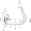
- FIG. 1 illustrates a hose storage unit 100 for storing a hose 102 (as shown in FIG. 5 ) at a tap 104 (as shown in FIG. 5 ).
- the hose storage unit 100 may be used to store hoses 102 having different lengths and types. The length and the type of the hose 102 may vary depending upon application requirements.
- the hose 102 may be used for a number of indoor and outdoor applications.
- the tap 104 may supply any type of liquid, without limiting the scope of the present invention. In the illustrated embodiment, the tap 104 supplies water. In application, water from the tap 104 may flow through the hose 102.
- the tap 104 may include any type of tap such as a wall mounted tap, a pillar tap, a mixer tap, and the like.
- the hose storage unit 100 includes a storage hook 106 to receive the hose 102.
- the storage hook 106 has a substantially C-shaped, or U-shaped structure.
- the storage hook 106 includes a first end 108, a second end 110, and a vertical portion 112.
- the vertical portion 112 extends between the first and second ends 108, 110.
- the storage hook 106 also includes a first surface 114 and a second surface 116.
- the first surface 114 and second surface 116 include a generally curved shaped profile.
- the first end 108 defines a first thickness "T1" .
- the storage hook 106 defines a through hole 118 (as shown in FIG. 3 ) proximate the first end 108 to receive a screw lock 120 (as shown in FIG. 3 ).
- the screw lock 120 may allow selective locking i.e., rotational locking of the storage hook 106.
- the screw lock 120 may allow selective locking of the storage hook 106 at any angular position or orientation with respect to a central axis " A1" of an adaptor 130.
- the screw lock 120 may be movable within the through hole 118 to allow locking of the storage hook 106 with one or more of the adaptor 130, and the tap 104.
- the second end 110 defines a second thickness "T2". Further, in some embodiments, the second thickness "T2" is greater than the first thickness "T1" . Alternatively, the second thickness "T2" may be equal to the first thickness "T1".
- the storage hook 106 may be manufactured using a material such as a synthetic plastic, a metal alloy, and the like. It should be noted that the material of the storage hook 106 does not limit the scope of the present invention.
- the storage hook 106 further includes a hose receiving portion 122 to receive the hose 102.
- the hose receiving portion 122 is disposed proximate the second end 110 of the storage hook 106.
- the hose receiving portion 122 may include a rough surface (or elements or features such as knurling) to promote gripping and/or inadvertent movement of the stored hose 102. Further, the hose receiving portion 122 receives the hose 102 in a coiled or wound form.
- the hose 102 may be folded into a number of coils to store the coiled hose 102 on the hose receiving portion 122.
- the hose receiving portion 122 of the storage hook 106 is inclined with respect to the central axis " A1" of an adaptor 130 (as shown in FIG. 2 ). Further, the inclination of the hose receiving portion 122 with respect to the central axis " A1” may vary between 0 degree to 90 degrees. In some embodiments, the inclination of the hose receiving portion 122 with respect to the central axis " A1" may lie between 35 degrees and 70 degrees. In some embodiments, the hose receiving portion 122 of the storage hook 106 is substantially horizontal. In such an example, the hose receiving portion 122 may be substantially perpendicular to the vertical portion 112. In yet other embodiments, the storage hook 106 has a "U" shape. In such an example, the second end 110 may be disposed substantially parallel to the vertical portion 112.
- the storage hook 106 includes a hole 132 to receive the adaptor 130.
- the hole 132 may be embodied as a through-hole.
- the hole 132 may define an internal threading (not shown).
- the hole 132 may include a counterbore hole, a countersink hole, and the like.
- the hole 132 is disposed proximate the first end 108 of the storage hook 106.
- the hole 132 defines a hole diameter "D1".
- a shape and a size of the hole 132 is designed based on the shape and size of the adaptor 130.
- the hose storage unit 100 also includes a tap connector 134 to fluidly connect the hose 102 (see FIG. 5 ) and the tap 104 (see FIG. 5 ).
- the tap connector 134 includes a first coupling portion 138 to couple the tap connector 134 with the adaptor 130 and a second coupling portion 140 forming a liquid outlet.
- the second coupling portion 140 receives a hose connector 142 (as shown in FIG. 5 ).
- a washer 136 may be provided within the first coupling portion 138 to provide a liquid-tight connection between the tap connector 134 and the adaptor 130.
- the hose storage unit 100 further includes the adaptor 130.
- the adaptor 130 fluidly couples the tap 104 with the tap connector 134.
- the adaptor 130 is removably coupled with the tap 104 and engaged with the tap connector 134.
- the adaptor 130 is threadably coupled with the tap 104.
- the adaptor 130 receives an outlet portion 144 (as shown in FIGS. 4A and 4B ) of the tap 104.
- the coupling between the adaptor 130 and the tap connector 134 is a thread coupling, or any other coupling such as a press-fit, a snap-fit and like coupling as used or known in the art.
- the adaptor 130 includes a first portion 146 defining a diameter "D2 and a thickness "T3".
- the first portion 146 may define a blind hole to receive the screw lock 120 (see FIG. 3 ).
- the first portion 146 may also define a number of internal threads (not shown).
- the adaptor 130 also includes a second portion 148 defining a diameter "D3" and a thickness "T4". Further, the diameter "D2" of the first portion 146 is greater than the diameter "D3" of the second portion 148.
- the second portion 148 defines a number of external threads 152.
- the tap connector 134 receives the second portion 148 of the adaptor 130.
- the adaptor 130 further includes a sealing element 154 disposed between the first portion 146 thereof and the outlet portion 144 of the tap 104 for a leak-proof coupling between the adaptor 130 and the tap 104.
- the sealing element 154 may include one or more washers, seals and the like and provides water as well as connection tightness at a connection between the adapter 130 and the tap 104.
- the storage hook 106 may be secured to the adaptor 130 using the screw lock 120. Further, the storage hook 106 is associated with (say coupled around) the adaptor 130. in the illustrated embodiment, the storage hook 106 is removably coupled around the adaptor 130 and the tap connector 134. More particularly, the storage hook 106 is coupled around the adaptor 130 proximate the first end 108 of the storage hook 106. The adaptor 130 is received by the hole 132 of the storage hook 106 since the diameter "D2" of the first portion 146 of the adaptor 130 is approximately equal to the hole diameter "D1" of the hole 132.
- the hole 132 may partially receive the adaptor 130 since the thickness "T3" of the first portion 146 of the adaptor 130 is greater than the thickness "T1" of the first end 108 of the storage hook 106. Further, the counterbore or countersink profile of the hole 132 may receive the second portion 148 of the adaptor 130. A combined thickness "T2", "T3" of the adapter 130 is greater than the first thickness "T1" of the first end 108 of the storage hook 106.
- a portion of the adapter 130 at the first portion 146 extends out partially in an upward direction from the storage hook 106 to couple with the outlet portion 144 of the tap 104 and a portion of the adapter 130 at the second portion 148 extends out partially in a downward direction from the storage hook 106 to receive the tap connector 134 (see FIG. 5 ). Furthermore, the thickness "T4" of the second portion 148 of the adaptor 130 is greater than the thickness "T1" of the first end 108 of the storage hook 106.
- the storage hook 106 may be coupled around the adaptor 130. This may allow implementation benefits along with ease of assembly or disassembly of the storage hook 106 with the adaptor 130.
- the storage hook 106 may be fixed with the adaptor 130. The fixing of the storage hook 106 with the adaptor 130 may allow selective locking or rotation of the storage hook 106 with respect to the adaptor 130. Further, the fixing of the storage hook 106 with the adaptor 130 may include application of one or more of a glue, fasteners, and the like, or any fastening means as used or known in the art.
- the storage hook 106 may be integral with the adaptor 130. This may lead to manufacturing and service benefits, for application of the storage hook 106 and the adaptor 130. The present disclosure allows any association, arrangement, coupling, fixing, and the like between the storage hook 106 and the adaptor 130, and all such variations are well within the scope of the present disclosure.
- FIGS. 4A, 4B , 4C, and 4D show the assembly of the hose storage unit 100 with the tap 104 (see FIG. 5 ).
- the adaptor 130, the storage hook 106, the tap connector 134, and the tap 104 are shown in an unassembled configuration.
- the adaptor 130 is threadably coupled to the outlet portion 144 of the tap 104.
- the outlet portion 144 of the tap 104 may define external threads (not shown) for threadable coupling of the adaptor 130.
- FIG. 4C in a third position, the storage hook 106 is coupled around the adaptor 130.
- the tap connector 134 is threadably coupled to the second portion 148 of the adaptor 130 to fluidly connect the tap connector 134 (and thereby the hose 102, see FIG. 5 ) and the tap 104.
- the hose connector 142 is coupled to the second coupling portion 140 of the tap connector 134.
- the hose connector 142 may include a body portion (not shown) having an arrangement such as threads that allow engagement of the hose 102 with the hose connector 142.
- the present invention provides an improved and simplified design of the hose storage unit 100 which allows easy installation.
- the new design of the hose storage unit 100 can be accommodated in compact spaces.
- the hose storage unit 100 does not require an external structure such as a wall for mounting the hose storage unit 100 or components thereof and can be directly stored proximate the tap 104.
- the hose storage unit 100 includes fewer parts thus making the assembly simple in design and cost effective.
- the storage hook 106 is directly connected to the adaptor 130 as a screw element. Therefore, a liquid can be fed directly into the hose 102 through the adaptor 130.
- the storage hook 106 can be rotated relative to the tap 104 around the central axis " A1" of the adaptor 130, thereby allowing storage of the hose 102 at various positions relative to the tap 104.
- the hose storage unit 100 user friendly and improves ergonomics.
- the hose 102 can be quickly assembled and disassembled from the tap 104 using the hose storage unit 100 described herein.
- the adaptor 130 includes the sealing element 154 that provides tightness between the hose storage unit 100 and the tap 104.
- the hose 102 is stored on the storage hook 106 which is coupled to the adaptor 130 hence the weight of the hose 102 is supported by the adaptor 130 thereby preventing damage and breakdown at the hose connection.
Landscapes
- Supports For Pipes And Cables (AREA)
- Quick-Acting Or Multi-Walled Pipe Joints (AREA)
- Domestic Plumbing Installations (AREA)
Abstract
A hose storage unit (100) for storing a hose (102) at a tap (104). The hose storage unit (100) includes a storage hook (106) to receive the hose (102). The hose storage also includes a tap connector (134) to fluidly connect the hose (102) and the tap (104). The hose storage unit (100) is characterized in that an adaptor (130) is removably coupled with the tap (104) and engaged with the tap connector (134). The adaptor (130) fluidly couples the tap (104) with the tap connector (134). Further, the storage hook (106) is associated with the adaptor (130).
Description
- The present disclosure relates to a hose storage unit for storing a hose.
- A hose storage device for storing a hose, specifically a water hose, is well-known. Such hose storage devices are generally mounted on a wall, a cabinet, and the like, which may increase components associated with the hose storage devices. This additional mounting of such components of the hose storage device may be challenging in some situations. The hose storage device typically includes a hose trolley or a hose box. The hose trolleys or the hose boxes require increased space on a floor or may have to be firmly mounted to the wall. Typically, such arrangements are not useful for short hoses. Further, the hose trolleys or the hose boxes are expensive which increase an overall cost associated with the hose storage device.
- Additionally, different hose storage devices have been developed for storing the water hose around a water tap. Such hose storage devices generally include a hose holder or hanger which is coupled to the water tap. However, such hose storage device also face constraints due to involvement of a large number of components, connection joints, attachments, and the like. The hose holder or hanger may also put pressure on connection of the hose storage device with the tap. Thus, there is a need for an improved design of the hose storage device which provides a simple and cost-effective means for hose storage and can be used for different (say short) hoses.
- An example of a hose holder is provided in
WO Patent Application 2017/148,522 (hereinafter referred to as '522 reference). The '522 reference discloses the hose holder for storing a hose at a water tap. The hose holder includes a connection portion for connecting a holding device with the water tap and a holding portion for receiving the hose. The connection portion includes a tap connection portion for mechanically and fluidly coupling the hose holder with the water tap. The holding portion includes a hose receiving area for supporting the coiled hose in a hanging position such that the windings of the coiled hose are arranged in a vertical plane. However, in this type of the hose holder a weight of the hose is directly supported by the tap connection portion, which may lead to unintended disassembly or accidents. Moreover, hoses having a longer length are generally heavier which may damage the tap connection portion leading to leakage or complete break-off. - In view of the above, it is an objective of the present disclosure to solve or at least reduce the drawbacks discussed above. The objective is at least partially achieved by a new design of a hose storage unit for storing a hose at a tap. The hose storage includes a storage hook to receive the hose. The hose storage also includes a tap connector to fluidly connect the hose and the tap. The hose storage unit is characterized in that an adaptor is removably coupled with the tap and engaged with the tap connector. The adaptor fluidly couples the tap with the tap connector. Further, the storage hook is associated with the adaptor.
- The present disclosure provides an improved design of the hose storage unit which allows quick and easy installation of the hose at the tap. The new design of the hose storage unit can be installed in a compact space and is readily compatible. Further, the hose storage unit does not require an external structure such as a wall for mounting the hose storage units or components thereof. The hose storage unit includes fewer parts thus making the assembly simple and cost effective. Further, the storage hook is directly connected to the adaptor which acts as a screw element. Therefore, a liquid can be fed directly into the hose through the adaptor, and the tap connector. A circular arrangement of the hose storage unit allows the storage hook to rotate around a central axis of the adaptor which makes the hose storage unit user friendly and provides improved ergonomics. Further, the tap connector includes a sealing element that provides tightness of the hose storage unit with an existing tap. Moreover, the hose is stored on the storage hook which is associated (or coupled) to the adaptor hence a weight of the hose is supported by the adaptor which prevents damage and breakdown at the hose connection.
- According to an embodiment of the present disclosure, the storage hook is associated with the adaptor by coupling the storage hook (106) around the adaptor (130). This may allow implementation benefits along with ease of assembly or disassembly of the storage hook with the adaptor.
- According to an embodiment of the present disclosure, the storage hook is associated with the adaptor by fixing the storage hook with the adaptor. The fixing of the storage hook with the adaptor may include application of one or more of a glue, fasteners, and the like.
- According to an embodiment of the present disclosure, the storage hook is associated with the adaptor by having the storage hook to be integral with the adaptor. This may lead to manufacturing and service benefits, for application of the storage hook and the adaptor.
- According to an embodiment of the present disclosure, the coupling between the adaptor and the tap connector is a thread coupling. The coupling may be any type of coupling such as the thread coupling which provides ease in assembly and rigidity to a connection between the adaptor and the tap connector.
- According to an embodiment of the present disclosure, the adaptor is threadably coupled with the tap. The thread coupling provides ease in assembly and rigidity to a connection between the adaptor and the tap, though the coupling may be any coupling such as snap-fit, press-fit or any other as used or known in the art.
- According to an embodiment of the present disclosure, the storage hook is removably coupled around the adaptor and the tap connector. Such a removable coupling provides flexibility to use the hose storage unit for different taps thereby providing a versatile and modular hose storage unit. Further, the hose storage unit may be quickly dissembled when not in use.
- According to an embodiment of the present disclosure, the storage hook includes a hose receiving portion to receive the hose. The hose receiving portion allows the user to store (say winding or looping) the hose on the storage hook.
- According to an embodiment of the present disclosure, the hose receiving portion of the storage hook is substantially horizontal. The substantially horizontal hose receiving portion provides a larger and stable area for holding of the hose in a horizontal configuration.
- According to an embodiment of the present disclosure, the hose receiving portion of the storage hook is inclined with respect to the central axis of the adaptor. Such an inclined hose receiving portion allows the hose to be stored in an inclined configuration which provides easy and secure storage of the hose.
- According to an embodiment of the present disclosure, the storage hook has a "U" shape. The storage hook may have any shape (say "V", "L" and like shapes), size, type as per application requirements. This arrangement (i.e., the "U" shape of the present disclosure) of the storage hook may provide easy, stable, and secure storage of the hose.
- According to an embodiment of the present disclosure, the storage hook includes a hole to receive the adaptor. This arrangement provides easy assembly of the storage hook around the adaptor and thereby with the tap.
- Other features and aspects of this disclosure will be apparent from the following description and the accompanying drawings.
- The disclosure will be described in more detail with reference to the enclosed drawings, wherein:
-
FIG. 1 illustrates a side view of a hose storage unit, according to an embodiment of the present disclosure; -
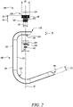
FIG. 2 illustrates an exploded view of the hose storage unit, according to an embodiment of the present disclosure; -
FIG. 3 illustrates a top view of the hose storage unit, according to an embodiment of the present disclosure; -
FIG. 4A illustrates a perspective view of the hose storage unit and a tap in a first position, according to an embodiment of the present disclosure; -
FIG. 4B illustrates a perspective view of the hose storage unit and the tap in a second position, according to an embodiment of the present disclosure; -
FIG. 4C illustrates a perspective view of the hose storage unit and the tap in a third position, according to an embodiment of the present disclosure; -
FIG. 4D illustrates a perspective view of the hose storage unit and the tap in a fourth position, according to an embodiment of the present disclosure; and - FIG. 5 illustrates a perspective view of the hose storage unit and a hose, according to an embodiment of the present disclosure.
- The present disclosure will be described more fully hereinafter with reference to the accompanying drawings, in which example embodiments of the disclosure incorporating one or more aspects of the present disclosure are shown. This disclosure may, however, be embodied in many different forms and should not be construed as limited to the embodiments set forth herein; rather, these embodiments are provided so that this disclosure will be thorough and complete, and will fully convey the scope of the disclosure to those skilled in the art. For example, one or more aspects of the present disclosure may be utilized in other embodiments and even other types of structures and/or methods. In the drawings, like numbers refer to like elements.
- Certain terminology is used herein for convenience only and is not to be taken as a limitation on the disclosure. For example, "upper", "lower", "front", "rear", "side", "longitudinal", "lateral", "transverse", "upwards", "downwards", "forward", "backward", "sideward", "left," "right," "horizontal," "vertical," "upward", "inner", "outer", "inward", "outward", "top", "bottom", "higher", "above", "below", "central", "middle", "intermediate", "between", "end", "adjacent", "proximate", "near", "distal", "remote", "radial", "circumferential", or the like, merely describe the configuration shown in the Figures. Indeed, the components may be oriented in any direction and the terminology, therefore, should be understood as encompassing such variations unless specified otherwise.
-
FIG. 1 illustrates ahose storage unit 100 for storing a hose 102 (as shown in FIG. 5) at a tap 104 (as shown in FIG. 5). Thehose storage unit 100 may be used to storehoses 102 having different lengths and types. The length and the type of thehose 102 may vary depending upon application requirements. Thehose 102 may be used for a number of indoor and outdoor applications. Further, thetap 104 may supply any type of liquid, without limiting the scope of the present invention. In the illustrated embodiment, thetap 104 supplies water. In application, water from thetap 104 may flow through thehose 102. Thetap 104 may include any type of tap such as a wall mounted tap, a pillar tap, a mixer tap, and the like. - The
hose storage unit 100 includes astorage hook 106 to receive thehose 102. Thestorage hook 106 has a substantially C-shaped, or U-shaped structure. Thestorage hook 106 includes afirst end 108, asecond end 110, and avertical portion 112. Thevertical portion 112 extends between the first and second ends 108, 110. Thestorage hook 106 also includes afirst surface 114 and asecond surface 116. Thefirst surface 114 andsecond surface 116 include a generally curved shaped profile. Thefirst end 108 defines a first thickness "T1". Thestorage hook 106 defines a through hole 118 (as shown inFIG. 3 ) proximate thefirst end 108 to receive a screw lock 120 (as shown inFIG. 3 ). In some embodiments, thescrew lock 120 may allow selective locking i.e., rotational locking of thestorage hook 106. Thescrew lock 120 may allow selective locking of thestorage hook 106 at any angular position or orientation with respect to a central axis "A1" of anadaptor 130. In some embodiments, thescrew lock 120 may be movable within the throughhole 118 to allow locking of thestorage hook 106 with one or more of theadaptor 130, and thetap 104. - The
second end 110 defines a second thickness "T2". Further, in some embodiments, the second thickness "T2" is greater than the first thickness "T1". Alternatively, the second thickness "T2" may be equal to the first thickness "T1". Thestorage hook 106 may be manufactured using a material such as a synthetic plastic, a metal alloy, and the like. It should be noted that the material of thestorage hook 106 does not limit the scope of the present invention. - The
storage hook 106 further includes ahose receiving portion 122 to receive thehose 102. Thehose receiving portion 122 is disposed proximate thesecond end 110 of thestorage hook 106. Thehose receiving portion 122 may include a rough surface (or elements or features such as knurling) to promote gripping and/or inadvertent movement of the storedhose 102. Further, thehose receiving portion 122 receives thehose 102 in a coiled or wound form. Thehose 102 may be folded into a number of coils to store the coiledhose 102 on thehose receiving portion 122. In the illustrated embodiment, thehose receiving portion 122 of thestorage hook 106 is inclined with respect to the central axis "A1" of an adaptor 130 (as shown inFIG. 2 ). Further, the inclination of thehose receiving portion 122 with respect to the central axis "A1" may vary between 0 degree to 90 degrees. In some embodiments, the inclination of thehose receiving portion 122 with respect to the central axis "A1" may lie between 35 degrees and 70 degrees. In some embodiments, thehose receiving portion 122 of thestorage hook 106 is substantially horizontal. In such an example, thehose receiving portion 122 may be substantially perpendicular to thevertical portion 112. In yet other embodiments, thestorage hook 106 has a "U" shape. In such an example, thesecond end 110 may be disposed substantially parallel to thevertical portion 112. - Referring to
FIG. 2 , thestorage hook 106 includes ahole 132 to receive theadaptor 130. Thehole 132 may be embodied as a through-hole. Thehole 132 may define an internal threading (not shown). Thehole 132 may include a counterbore hole, a countersink hole, and the like. Thehole 132 is disposed proximate thefirst end 108 of thestorage hook 106. Thehole 132 defines a hole diameter "D1". A shape and a size of thehole 132 is designed based on the shape and size of theadaptor 130. - The
hose storage unit 100 also includes atap connector 134 to fluidly connect the hose 102 (see FIG. 5) and the tap 104 (see FIG. 5). Thetap connector 134 includes afirst coupling portion 138 to couple thetap connector 134 with theadaptor 130 and asecond coupling portion 140 forming a liquid outlet. Thesecond coupling portion 140 receives a hose connector 142 (as shown in FIG. 5). Further, awasher 136 may be provided within thefirst coupling portion 138 to provide a liquid-tight connection between thetap connector 134 and theadaptor 130. - The
hose storage unit 100 further includes theadaptor 130. Theadaptor 130 fluidly couples thetap 104 with thetap connector 134. Theadaptor 130 is removably coupled with thetap 104 and engaged with thetap connector 134. In particular, theadaptor 130 is threadably coupled with thetap 104. Theadaptor 130 receives an outlet portion 144 (as shown inFIGS. 4A and 4B ) of thetap 104. Furthermore, the coupling between theadaptor 130 and thetap connector 134 is a thread coupling, or any other coupling such as a press-fit, a snap-fit and like coupling as used or known in the art. - The
adaptor 130 includes afirst portion 146 defining a diameter "D2 and a thickness "T3". Thefirst portion 146 may define a blind hole to receive the screw lock 120 (seeFIG. 3 ). Thefirst portion 146 may also define a number of internal threads (not shown). Theadaptor 130 also includes asecond portion 148 defining a diameter "D3" and a thickness "T4". Further, the diameter "D2" of thefirst portion 146 is greater than the diameter "D3" of thesecond portion 148. Moreover, thesecond portion 148 defines a number ofexternal threads 152. In the illustrated embodiment, thetap connector 134 receives thesecond portion 148 of theadaptor 130. Theadaptor 130 further includes a sealingelement 154 disposed between thefirst portion 146 thereof and theoutlet portion 144 of thetap 104 for a leak-proof coupling between theadaptor 130 and thetap 104. The sealingelement 154 may include one or more washers, seals and the like and provides water as well as connection tightness at a connection between theadapter 130 and thetap 104. - As shown in
FIGS. 1 and3 , thestorage hook 106 may be secured to theadaptor 130 using thescrew lock 120. Further, thestorage hook 106 is associated with (say coupled around) theadaptor 130. in the illustrated embodiment, thestorage hook 106 is removably coupled around theadaptor 130 and thetap connector 134. More particularly, thestorage hook 106 is coupled around theadaptor 130 proximate thefirst end 108 of thestorage hook 106. Theadaptor 130 is received by thehole 132 of thestorage hook 106 since the diameter "D2" of thefirst portion 146 of theadaptor 130 is approximately equal to the hole diameter "D1"of thehole 132. Thehole 132 may partially receive theadaptor 130 since the thickness "T3" of thefirst portion 146 of theadaptor 130 is greater than the thickness "T1" of thefirst end 108 of thestorage hook 106. Further, the counterbore or countersink profile of thehole 132 may receive thesecond portion 148 of theadaptor 130. A combined thickness "T2", "T3" of theadapter 130 is greater than the first thickness "T1" of thefirst end 108 of thestorage hook 106. Further, a portion of theadapter 130 at thefirst portion 146 extends out partially in an upward direction from thestorage hook 106 to couple with theoutlet portion 144 of thetap 104 and a portion of theadapter 130 at thesecond portion 148 extends out partially in a downward direction from thestorage hook 106 to receive the tap connector 134 (see FIG. 5). Furthermore, the thickness "T4" of thesecond portion 148 of theadaptor 130 is greater than the thickness "T1" of thefirst end 108 of thestorage hook 106. - In some embodiments, the
storage hook 106 may be coupled around theadaptor 130. This may allow implementation benefits along with ease of assembly or disassembly of thestorage hook 106 with theadaptor 130. In some embodiments, thestorage hook 106 may be fixed with theadaptor 130. The fixing of thestorage hook 106 with theadaptor 130 may allow selective locking or rotation of thestorage hook 106 with respect to theadaptor 130. Further, the fixing of thestorage hook 106 with theadaptor 130 may include application of one or more of a glue, fasteners, and the like, or any fastening means as used or known in the art. In some embodiments, thestorage hook 106 may be integral with theadaptor 130. This may lead to manufacturing and service benefits, for application of thestorage hook 106 and theadaptor 130. The present disclosure allows any association, arrangement, coupling, fixing, and the like between thestorage hook 106 and theadaptor 130, and all such variations are well within the scope of the present disclosure. -
FIGS. 4A, 4B ,4C, and 4D show the assembly of thehose storage unit 100 with the tap 104 (see FIG. 5). Referring toFIG. 4A , in a first position, theadaptor 130, thestorage hook 106, thetap connector 134, and thetap 104 are shown in an unassembled configuration. Referring toFIG. 4B , in a second position, theadaptor 130 is threadably coupled to theoutlet portion 144 of thetap 104. Theoutlet portion 144 of thetap 104 may define external threads (not shown) for threadable coupling of theadaptor 130. Referring toFIG. 4C , in a third position, thestorage hook 106 is coupled around theadaptor 130. This removable coupling of thestorage hook 106 allows thestorage hook 106 to be rotated at 360 degrees about the central axis "A1" of theadaptor 130. Referring toFIG. 4D , in a fourth position, thetap connector 134 is threadably coupled to thesecond portion 148 of theadaptor 130 to fluidly connect the tap connector 134 (and thereby thehose 102, see FIG. 5) and thetap 104. As shown in FIG. 5, thehose connector 142 is coupled to thesecond coupling portion 140 of thetap connector 134. Thehose connector 142 may include a body portion (not shown) having an arrangement such as threads that allow engagement of thehose 102 with thehose connector 142. - The present invention provides an improved and simplified design of the
hose storage unit 100 which allows easy installation. The new design of thehose storage unit 100 can be accommodated in compact spaces. Further, thehose storage unit 100 does not require an external structure such as a wall for mounting thehose storage unit 100 or components thereof and can be directly stored proximate thetap 104. Thehose storage unit 100 includes fewer parts thus making the assembly simple in design and cost effective. Further, thestorage hook 106 is directly connected to theadaptor 130 as a screw element. Therefore, a liquid can be fed directly into thehose 102 through theadaptor 130. - Moreover, the
storage hook 106 can be rotated relative to thetap 104 around the central axis "A1" of theadaptor 130, thereby allowing storage of thehose 102 at various positions relative to thetap 104. Such a design makes thehose storage unit 100 user friendly and improves ergonomics. Additionally, thehose 102 can be quickly assembled and disassembled from thetap 104 using thehose storage unit 100 described herein. Further, theadaptor 130 includes the sealingelement 154 that provides tightness between thehose storage unit 100 and thetap 104. Moreover, thehose 102 is stored on thestorage hook 106 which is coupled to theadaptor 130 hence the weight of thehose 102 is supported by theadaptor 130 thereby preventing damage and breakdown at the hose connection. - In the drawings and specification, there have been disclosed preferred embodiments and examples of the disclosure and, although specific terms are employed, they are used in a generic and descriptive sense only and not for the purpose of limitation of the scope of the disclosure being set forth in the following claims.
-
- 100
- Hose Storage Unit
- 102
- Hose
- 104
- Tap
- 106
- Storage Hook
- 108
- First End
- 110
- Second End
- 112
- Vertical Portion
- 114
- First Surface
- 116
- Second Surface
- 118
- Through Hole
- 120
- Screw Lock
- 122
- Hose Receiving Portion
- 130
- Adaptor
- 132
- Hole
- 134
- Tap Connector
- 136
- Washer
- 138
- First Coupling Portion
- 140
- Second Coupling Portion
- 142
- Hose Connector
- 144
- Outlet Portion
- 146
- First Portion
- 148
- Second Portion
- 152
- External Threads
- 154
- Sealing Element
- A1
- Central Axis
- D1
- Hole Diameter
- D2
- Diameter of First Portion
- D3
- Diameter of Second Portion
- T1
- Thickness of First End
- T2
- Thickness of Second End
- T3
- Thickness of First Portion
- T4
- Thickness of Second Portion
Claims (12)
- A hose storage unit (100) for storing a hose (102) at a tap (104), comprising:a storage hook (106) adapted to receive the hose (102); anda tap connector (134) adapted to fluidly connect the hose (102) and the tap (104);characterized in that:
an adaptor (130) removably coupled with the tap (104) and engaged with the tap connector (134), wherein the adaptor (130) fluidly couples the tap (104) with the tap connector (134), and wherein the storage hook (106) is associated with the adaptor (130). - The hose storage unit (100) of claim 1, wherein the storage hook (106) is associated with the adaptor (130) by coupling the storage hook (106) around the adaptor (130).
- The hose storage unit (100) of claim 2, wherein the storage hook (106) is removably coupled around the adaptor (130) and the tap connector (134).
- The hose storage unit (100) of claim 1, wherein the storage hook (106) is associated with the adaptor (130) by fixing the storage hook (106) with the adaptor (130).
- The hose storage unit (100) of claim 1, wherein the storage hook (106) is associated with the adaptor (130) by having the storage hook (106) to be integral with the adaptor (130).
- The hose storage unit (100) of any of the preceding claims, wherein the coupling between the adaptor (130) and the tap connector (134) is a thread coupling.
- The hose storage unit (100) of any of the preceding claims, wherein the adaptor (130) is threadably coupled with the tap (104).
- The hose storage unit (100) of any of the preceding claims, wherein the storage hook (106) includes a hose receiving portion (122) to receive the hose (102).
- The hose storage unit (100) of claim 8, wherein the hose receiving portion (122) of the storage hook (106) is substantially horizontal.
- The hose storage unit (100) of claim 8, wherein the hose receiving portion (122) of the storage hook (106) is inclined with respect to a central axis ("A1") of the adaptor (130).
- The hose storage unit (100) of any of the preceding claims, wherein the storage hook (106) has a "U" shape.
- The hose storage unit (100) of any of the preceding claims, wherein the storage hook (106) includes a hole (132) to receive the adaptor (130).
Priority Applications (4)
| Application Number | Priority Date | Filing Date | Title |
|---|---|---|---|
| EP21158863.7A EP4049957A1 (en) | 2021-02-24 | 2021-02-24 | Hose storage unit for storing hose |
| CN202180094521.6A CN116897133B (en) | 2021-02-24 | 2021-11-30 | Hose storage unit for storing hoses |
| EP21824320.2A EP4240682B1 (en) | 2021-02-24 | 2021-11-30 | Hose storage unit for storing hose |
| PCT/EP2021/083640 WO2022179730A1 (en) | 2021-02-24 | 2021-11-30 | Hose storage unit for storing hose |
Applications Claiming Priority (1)
| Application Number | Priority Date | Filing Date | Title |
|---|---|---|---|
| EP21158863.7A EP4049957A1 (en) | 2021-02-24 | 2021-02-24 | Hose storage unit for storing hose |
Publications (1)
| Publication Number | Publication Date |
|---|---|
| EP4049957A1 true EP4049957A1 (en) | 2022-08-31 |
Family
ID=74732700
Family Applications (2)
| Application Number | Title | Priority Date | Filing Date |
|---|---|---|---|
| EP21158863.7A Withdrawn EP4049957A1 (en) | 2021-02-24 | 2021-02-24 | Hose storage unit for storing hose |
| EP21824320.2A Active EP4240682B1 (en) | 2021-02-24 | 2021-11-30 | Hose storage unit for storing hose |
Family Applications After (1)
| Application Number | Title | Priority Date | Filing Date |
|---|---|---|---|
| EP21824320.2A Active EP4240682B1 (en) | 2021-02-24 | 2021-11-30 | Hose storage unit for storing hose |
Country Status (3)
| Country | Link |
|---|---|
| EP (2) | EP4049957A1 (en) |
| CN (1) | CN116897133B (en) |
| WO (1) | WO2022179730A1 (en) |
Families Citing this family (1)
| Publication number | Priority date | Publication date | Assignee | Title |
|---|---|---|---|---|
| DE102024122475A1 (en) * | 2024-08-07 | 2026-02-12 | Timm Greschner | Hose holder |
Citations (5)
| Publication number | Priority date | Publication date | Assignee | Title |
|---|---|---|---|---|
| US2111811A (en) * | 1937-03-05 | 1938-03-22 | John N Schichtel | Fire hose rack |
| US2569857A (en) * | 1946-03-06 | 1951-10-02 | Klingerit Inc | Combined mixing unit and hose rack |
| US20090272857A1 (en) * | 2008-05-01 | 2009-11-05 | Presidential Partners,L.L.C. | Faucet-supported hose retaining apparatus |
| KR20110024876A (en) * | 2009-09-03 | 2011-03-09 | 이정신 | Fire Hose Hanger |
| WO2017148522A1 (en) | 2016-03-03 | 2017-09-08 | Husqvarna Ab | Hose holder |
Family Cites Families (6)
| Publication number | Priority date | Publication date | Assignee | Title |
|---|---|---|---|---|
| US5005790A (en) * | 1988-10-31 | 1991-04-09 | Harris Iii John H | Hose holding fixture |
| JP3141067B2 (en) * | 1999-04-16 | 2001-03-05 | 株式会社フジアウテック | Watering hose storage hanger |
| EP2709938B1 (en) * | 2011-05-16 | 2015-07-01 | Alfred Kärcher GmbH & Co. KG | Hose retaining device |
| RU2015145506A (en) * | 2013-03-26 | 2017-05-18 | Хускварна Аб | PACKAGING PACKAGING FOR HOSE COIL |
| CN108290702B (en) * | 2015-10-01 | 2019-11-05 | As 美国股份有限公司 | Pulling out leading hose retraction system and method |
| US9748755B1 (en) * | 2016-09-21 | 2017-08-29 | Siemens Industry, Inc. | Clip-based non-metallic fittings for attachment of flexible metallic conduit |
-
2021
- 2021-02-24 EP EP21158863.7A patent/EP4049957A1/en not_active Withdrawn
- 2021-11-30 CN CN202180094521.6A patent/CN116897133B/en active Active
- 2021-11-30 EP EP21824320.2A patent/EP4240682B1/en active Active
- 2021-11-30 WO PCT/EP2021/083640 patent/WO2022179730A1/en not_active Ceased
Patent Citations (5)
| Publication number | Priority date | Publication date | Assignee | Title |
|---|---|---|---|---|
| US2111811A (en) * | 1937-03-05 | 1938-03-22 | John N Schichtel | Fire hose rack |
| US2569857A (en) * | 1946-03-06 | 1951-10-02 | Klingerit Inc | Combined mixing unit and hose rack |
| US20090272857A1 (en) * | 2008-05-01 | 2009-11-05 | Presidential Partners,L.L.C. | Faucet-supported hose retaining apparatus |
| KR20110024876A (en) * | 2009-09-03 | 2011-03-09 | 이정신 | Fire Hose Hanger |
| WO2017148522A1 (en) | 2016-03-03 | 2017-09-08 | Husqvarna Ab | Hose holder |
Also Published As
| Publication number | Publication date |
|---|---|
| WO2022179730A1 (en) | 2022-09-01 |
| EP4240682B1 (en) | 2024-06-05 |
| CN116897133A (en) | 2023-10-17 |
| EP4240682A1 (en) | 2023-09-13 |
| CN116897133B (en) | 2026-04-10 |
Similar Documents
| Publication | Publication Date | Title |
|---|---|---|
| US5246254A (en) | Anti-kinking device for garden hoses | |
| US12448993B2 (en) | Rod connector system and methods of use | |
| US5005790A (en) | Hose holding fixture | |
| US6014985A (en) | Drop-in faucet valve | |
| US11535484B2 (en) | Hose reel | |
| EP4240682B1 (en) | Hose storage unit for storing hose | |
| US7874041B2 (en) | Suction tube for a vacuum cleaner | |
| EP4257897A1 (en) | Waterway integrated device and refrigerator having same | |
| US20080099091A1 (en) | Combination spout stop/bottom bushing | |
| JP5271584B2 (en) | Cosmetic cover | |
| US7614664B1 (en) | Fast-connecting joint for corrugated pipes | |
| JP5466500B2 (en) | Water pipe fitting | |
| EP3423388B1 (en) | Hose holder | |
| JP6456167B2 (en) | Water discharge device | |
| JP2009275892A (en) | Support for arranged object | |
| CN210890272U (en) | Water tap | |
| CN210216593U (en) | Tap fixing base, tap and counter basin | |
| CN214064054U (en) | Locking nut and pull-out faucet | |
| CN209733913U (en) | Water adding assembly for dish washing machine and dish washing machine with water adding assembly | |
| EP4257898A1 (en) | Water path integrated structure and refrigerator having same | |
| CN223549576U (en) | Pipe fitting connection structure and support | |
| CN223498909U (en) | Gravity ball assembly for pull tap | |
| CN212307761U (en) | Dish washing machine | |
| CN219374462U (en) | Handle and cooking container | |
| CN216964977U (en) | Watering can with multistage formula nozzle |
Legal Events
| Date | Code | Title | Description |
|---|---|---|---|
| PUAI | Public reference made under article 153(3) epc to a published international application that has entered the european phase |
Free format text: ORIGINAL CODE: 0009012 |
|
| STAA | Information on the status of an ep patent application or granted ep patent |
Free format text: STATUS: THE APPLICATION HAS BEEN PUBLISHED |
|
| STAA | Information on the status of an ep patent application or granted ep patent |
Free format text: STATUS: THE APPLICATION HAS BEEN WITHDRAWN |
|
| AK | Designated contracting states |
Kind code of ref document: A1 Designated state(s): AL AT BE BG CH CY CZ DE DK EE ES FI FR GB GR HR HU IE IS IT LI LT LU LV MC MK MT NL NO PL PT RO RS SE SI SK SM TR |
|
| 18W | Application withdrawn |
Effective date: 20220811 |