EP4049899A1 - Electrical equipment - Google Patents
Electrical equipment Download PDFInfo
- Publication number
- EP4049899A1 EP4049899A1 EP22155470.2A EP22155470A EP4049899A1 EP 4049899 A1 EP4049899 A1 EP 4049899A1 EP 22155470 A EP22155470 A EP 22155470A EP 4049899 A1 EP4049899 A1 EP 4049899A1
- Authority
- EP
- European Patent Office
- Prior art keywords
- wire harness
- floor panel
- vehicle
- cross member
- battery
- Prior art date
- Legal status (The legal status is an assumption and is not a legal conclusion. Google has not performed a legal analysis and makes no representation as to the accuracy of the status listed.)
- Granted
Links
Images




Classifications
-
- B—PERFORMING OPERATIONS; TRANSPORTING
- B60—VEHICLES IN GENERAL
- B60R—VEHICLES, VEHICLE FITTINGS, OR VEHICLE PARTS, NOT OTHERWISE PROVIDED FOR
- B60R16/00—Electric or fluid circuits specially adapted for vehicles and not otherwise provided for; Arrangement of elements of electric or fluid circuits specially adapted for vehicles and not otherwise provided for
- B60R16/02—Electric or fluid circuits specially adapted for vehicles and not otherwise provided for; Arrangement of elements of electric or fluid circuits specially adapted for vehicles and not otherwise provided for electric constitutive elements
- B60R16/0207—Wire harnesses
-
- B—PERFORMING OPERATIONS; TRANSPORTING
- B60—VEHICLES IN GENERAL
- B60K—ARRANGEMENT OR MOUNTING OF PROPULSION UNITS OR OF TRANSMISSIONS IN VEHICLES; ARRANGEMENT OR MOUNTING OF PLURAL DIVERSE PRIME-MOVERS IN VEHICLES; AUXILIARY DRIVES FOR VEHICLES; INSTRUMENTATION OR DASHBOARDS FOR VEHICLES; ARRANGEMENTS IN CONNECTION WITH COOLING, AIR INTAKE, GAS EXHAUST OR FUEL SUPPLY OF PROPULSION UNITS IN VEHICLES
- B60K1/00—Arrangement or mounting of electrical propulsion units
-
- B—PERFORMING OPERATIONS; TRANSPORTING
- B60—VEHICLES IN GENERAL
- B60R—VEHICLES, VEHICLE FITTINGS, OR VEHICLE PARTS, NOT OTHERWISE PROVIDED FOR
- B60R16/00—Electric or fluid circuits specially adapted for vehicles and not otherwise provided for; Arrangement of elements of electric or fluid circuits specially adapted for vehicles and not otherwise provided for
- B60R16/02—Electric or fluid circuits specially adapted for vehicles and not otherwise provided for; Arrangement of elements of electric or fluid circuits specially adapted for vehicles and not otherwise provided for electric constitutive elements
- B60R16/0207—Wire harnesses
- B60R16/0215—Protecting, fastening and routing means therefor
-
- B—PERFORMING OPERATIONS; TRANSPORTING
- B62—LAND VEHICLES FOR TRAVELLING OTHERWISE THAN ON RAILS
- B62D—MOTOR VEHICLES; TRAILERS
- B62D25/00—Superstructure or monocoque structure sub-units; Parts or details thereof not otherwise provided for
- B62D25/20—Floors or bottom sub-units
-
- B—PERFORMING OPERATIONS; TRANSPORTING
- B60—VEHICLES IN GENERAL
- B60K—ARRANGEMENT OR MOUNTING OF PROPULSION UNITS OR OF TRANSMISSIONS IN VEHICLES; ARRANGEMENT OR MOUNTING OF PLURAL DIVERSE PRIME-MOVERS IN VEHICLES; AUXILIARY DRIVES FOR VEHICLES; INSTRUMENTATION OR DASHBOARDS FOR VEHICLES; ARRANGEMENTS IN CONNECTION WITH COOLING, AIR INTAKE, GAS EXHAUST OR FUEL SUPPLY OF PROPULSION UNITS IN VEHICLES
- B60K1/00—Arrangement or mounting of electrical propulsion units
- B60K1/04—Arrangement or mounting of electrical propulsion units of the electric storage means for propulsion
- B60K2001/0405—Arrangement or mounting of electrical propulsion units of the electric storage means for propulsion characterised by their position
- B60K2001/0422—Arrangement under the front seats
-
- B—PERFORMING OPERATIONS; TRANSPORTING
- B60—VEHICLES IN GENERAL
- B60Y—INDEXING SCHEME RELATING TO ASPECTS CROSS-CUTTING VEHICLE TECHNOLOGY
- B60Y2306/00—Other features of vehicle sub-units
- B60Y2306/01—Reducing damages in case of crash, e.g. by improving battery protection
-
- B—PERFORMING OPERATIONS; TRANSPORTING
- B60—VEHICLES IN GENERAL
- B60Y—INDEXING SCHEME RELATING TO ASPECTS CROSS-CUTTING VEHICLE TECHNOLOGY
- B60Y2410/00—Constructional features of vehicle sub-units
- B60Y2410/115—Electric wiring; Electric connectors
Definitions
- the present invention relates to an electrical equipment.
- vehicle substructures each of which includes a high-voltage battery installed between a floor panel and a seat when an electric component such as a battery cannot be accommodated in an engine room or below the floor panel (see JP2019-206303A ).
- the vehicle substructure described in JP2019-206303A includes a cross member extending in a vehicle width direction so as to be located in front of the electric component, the cross member being attached with a wire harness extending in the vehicle width direction so as to be located between the electric component and the cross member.
- a hole penetrating in a vehicle front-rear direction is provided at a center portion of the cross member in the vehicle width direction, in which a connection part between an air-conditioner duct and another air-conditioner duct is disposed.
- the hole in which the connection part of the duct is provided at the center portion of the cross member in the vehicle width direction, when the wire harness is attached to the cross member, it is necessary to bypass the hole and set a mounting point of the wire harness with respect to the cross member.
- the wire harness deforms so as to bend upward.
- the impact of deformation of the wire harness may be applied above the floor panel and there is still room for improvement in preventing the impact of deformation of the wire harness from being applied above the floor panel.
- the present invention has been implemented focusing on the above-described circumstances and it is an objective of the present invention to provide electrical equipment capable of preventing, when an impact is applied to the vehicle from the vehicle width direction, the impact caused by deformation of the wire harness from being applied above the floor panel.
- an electrical equipment installed on a vehicle including: a cross member with a hole portion, the cross member extending in a vehicle width direction above a floor panel; and a first wire harness attached to the cross member so as to be located above the hole portion, the first wire harness extending in the vehicle width direction
- the electrical equipment including: an electric component installed on the floor panel; and a cover member installed on the floor panel so as to cover the electric component, wherein the cover member includes a side wall facing the first wire harness, and a bulging part bulging from a wall surface of the side wall toward the first wire harness, and the bulging part covers the first wire harness from above.
- An electrical equipment is installed on a vehicle, the vehicle including: a cross member with a hole portion, the cross member extending in a vehicle width direction above a floor panel; and a first wire harness attached to the cross member so as to be located above the hole portion, the first wire harness extending in the vehicle width direction, the electrical equipment including: an electric component installed on the floor panel; and a cover member installed on the floor panel so as to cover the electric component, wherein the cover member includes a side wall facing the first wire harness, and a bulging part bulging from a wall surface of the side wall toward the first wire harness, and the bulging part covers the first wire harness from above.
- FIGS. 1 to Figure 10 are diagrams illustrating a protective structure for an electrical equipment according to an embodiment of the present invention.
- up-down, front-rear and left-right directions are defined such that a front-rear direction of a vehicle on which a battery pack is mounted is the front-rear direction, a left-right direction of the vehicle (vehicle width direction) is the left-right direction and an up-down direction of the vehicle (vehicle height direction) is the up-down direction.
- a vehicle 1 includes a floor panel 2.
- a left-side side sill 3L is provided at a left end portion of the floor panel 2 and the left-side side sill 3L extends in the front-rear direction along the floor panel 2.
- a right-side side sill 3R is provided at a right end portion of the floor panel 2 and the right-side side sill 3R extends in the front-rear direction along the floor panel 2.
- a floor tunnel 4 is provided in a center portion of the floor panel 2 in a vehicle width direction and the floor tunnel 4 bulges upward from the floor panel 2.
- a front-side cross member 5 and a rear-side cross member 6 are attached between the floor tunnel 4 and the left-side side sill 3L, and the front-side cross member 5 and the rear-side cross member 6 extend in the vehicle width direction spaced apart in the front-rear direction.
- a front-side cross member 7 and a rear-side cross member 8 are attached between the floor tunnel 4 and the right-side side sill 3R, and the front-side cross member 7 and the rear-side cross member 8 extend in the vehicle width direction spaced apart in the front-rear direction.
- part of a wire harness 9 is attached to the front-side cross member 5 and the wire harness 9 extends in the vehicle width direction. More specifically, as shown in Figure 1 , the wire harness 9 extends in the front-rear direction along the right-side side sill 3R, branches from a center portion in a direction in which the right-side side sill 3R extends and extends to the floor tunnel 4 along the front-side cross member 7.
- the wire harness 9 extends in the vehicle width direction from the floor tunnel 4 along the front-side cross member 5 and then extends in the front-rear direction along the left-side side sill 3L.
- the front-side cross member 5 of the present embodiment constitutes a cross member and the wire harness 9 constitutes a first wire harness.
- the front-side cross member 5 includes a hole portion 5a formed at the center portion in the vehicle width direction.
- the hole portion 5a is intended to pass a vehicle-mounted component to be installed in the front-rear direction across the front-side cross member 5.
- a duct of an air conditioner to be installed in front of the front-side cross member 5 is passed through the hole portion 5a and the duct to be passed through the hole portion 5a extends behind the front-side cross member 5.
- the front-side cross member 5 includes a band-shaped member 10A.
- the band-shaped member 10A is provided above the hole portion 5a and configured to fix the center portion of the wire harness 9 in the vehicle width direction to the front-side cross member 5.
- the front-side cross member 5 includes band-shaped members 10B and 10C.
- the band-shaped members 10B and 10C are located below the band-shaped member 10A and at left and right end portions of the front-side cross member 5 in the vehicle width direction with respect to the band-shaped member 10A and configured to fix the left and right end portions of the wire harness 9 to the front-side cross member 5.
- the band-shaped member 10B is located on the left end side in the vehicle width direction with respect to the band-shaped member 10A and the band-shaped member 10C is located on the right end side in the vehicle width direction with respect to the band-shaped member 10A.
- the center portion of the wire harness 9 in the vehicle width direction and the left and right end portions in the vehicle width direction are based on the length of the front-side cross member 5 in the vehicle width direction, and mean the center portion of the region of the wire harness 9 routed in the vehicle width direction of the front-side cross member 5 and the left and right end portions in the vehicle width direction.
- the band-shaped member 10A of the present embodiment constitutes a first mounting part, and the band-shaped members 10B and 10C constitute second mounting parts.
- a battery pack 11 as an electrical apparatus is installed on an upper surface 2a of the floor panel 2 and the battery pack 11 is installed in a space between an assistant driver's seat (not shown) and the floor panel 2. Note that the battery pack 11 may also be installed in a space between the driver's seat (not shown) and the floor panel 2.
- the battery pack 11 Since the battery pack 11 is installed between the assistant driver's seat and the floor panel 2, the battery pack 11 can be installed in a vehicle room in a cooler environment than in an engine room, and performance of a battery 12, which will be described later, can be extracted more easily.
- the battery pack 11 is located among the left-side side sill 3L, the floor tunnel 4, the front-side cross member 5 and the rear-side cross member 6.
- the battery pack 11 includes the battery 12 as an electric component.
- the battery 12 includes a plurality of battery modules (not shown), a battery holder that accommodates the plurality of battery modules and protect the battery modules and a substrate part 23 provided on an upper surface of the battery holder.
- the battery 12 is provided with a plurality of fixing pieces 12A, 12B, 12C and 12D and the fixing pieces 12A, 12B, 12C and 12D protrude outward from the side surface of the battery 12 in the vehicle width direction (outward to the left and right).
- the floor panel 2 is provided with a bracket 14 and the bracket 14 is provided with fixing pieces 14A and 14B (see Figure 5 ).
- the fixing pieces 14A and 14B protrude upward from the right end portion of the bracket 14 and are located at positions higher than the upper surface 2a of the floor panel 2.
- the bracket 14 is provided with fixing pieces 14C and 14D (see Figure 5 ).
- the fixing pieces 14C and 14D protrude upward from a left end portion of the bracket 14 and are located at positions higher than the upper surface 2a of the floor panel 2.
- the fixing pieces 14A and 14B, and the fixing pieces 14C and 14D are located at the same height position.
- the fixing pieces 12A and 12B of the battery 12 are fixed to the fixing pieces 14A and 14B with bolts (not shown).
- the fixing pieces 12C and 12D of the battery 12 are fixed to the fixing pieces 14C and 14D with a bolt 51A.
- the fixing pieces 12A, 12B, 12C and 12D of the present embodiment constitute fixing parts.
- the battery 12 is fixed to the floor panel 2 via the bracket 14, to be upward away from the floor panel 2 by the bracket 14.
- the fixing pieces 14A, 14B, 14C and 14D of the present embodiment constitute fixed parts.
- terminal parts 13A and 13B are provided on an upper part of a front surface 12a of the battery 12, and the terminal parts 13A and 13B in a plan view of the vehicle 1 are installed side by side in the vehicle width direction.
- the vehicle width direction is a direction L in which the terminal parts 13A and 13B are arranged.
- the arrangement direction L of the terminal parts 13A and 13B will be referred to as an arrangement direction L.
- the terminal parts 13A and 13B are installed above the fixing pieces 14A, 14B, 14C and 14D, and above a center portion C of the battery 12 in the height direction (see Figure 6 ). Note that the wire harness 9 is omitted in Figure 5 .
- the terminal parts 13A and 13B are located in front of the front surface 12a of the battery 12 and extend in the up-down direction. Note that the terminal parts 13A and 13B have an identical shape and overlap in the vehicle width direction.
- the terminal part 13A of the present embodiment constitutes a first terminal part and the terminal part 13B constitutes a second terminal part.
- the substrate part 23 is provided above the terminal parts 13A and 13B.
- the substrate part 23 is a control substrate configured to detect a remaining capacity of the battery module and control charging/discharging or the like.
- an opening portion 2b is formed on the floor panel 2.
- the opening portion 2b is located on the floor tunnel 4 side with respect to the terminal parts 13A and 13B, and is aligned with the arrangement direction L of the terminal parts in a plan view of the vehicle 1.
- the terminal part 13B is installed at a position farther from the opening portion 2b in the arrangement direction L of the terminal parts than the terminal part 13A.
- wire harnesses 21 and 22 are connected to the battery pack 11.
- the wire harnesses 21 and 22 are introduced into the cover member 15 through the opening portion 2b from below the floor panel 2, extends above the floor panel 2 (i.e., within the cover member 15) in the arrangement direction L of the terminal parts, and are connected to the terminal part 13A and the terminal part 13B via connectors 21C and 22C provided at end portions of the wire harnesses 21 and 22, respectively.
- the wire harnesses 21 and 22 are routed passing through the floor tunnel 4 below the floor panel 2 and the other end portion thereof is connected to another electric component such as an auxiliary machine. Thus, electric power of the battery 12 is supplied to the other electric component such as an auxiliary machine by the wire harnesses 21 and 22.
- the wire harnesses 21 and 22 of the present embodiment constitute a second wire harness.
- the battery pack 11 includes a cover member 15.
- the cover member 15 includes a ceiling wall 15A, and a front wall 15B, a rear wall 15C, a left side wall 15D and a right side wall 15E extending downward from the ceiling wall 15A.
- the ceiling wall 15A covers above the opening portion 2b, the upper surface of the battery 12 and the wire harnesses 21 and 22 from above.
- the front wall 15B covers the front surface 12a of the battery 12 and the wire harnesses 21 and 22, and the rear wall 15C, the left side wall 15D and the right side wall 15E cover the rear surface, the left side surface and the right side surface of the battery 12.
- the opening portion 2b is located inside the front wall 15B, the rear wall 15C, the left side wall 15D and the right side wall 15E, and is covered with the cover member 15.
- the front wall 15B, the rear wall 15C, the left side wall 15D and the right side wall 15E of the present embodiment constitute side walls.
- the front wall 15B of the cover member 15 faces the wire harness 9 in the front-rear direction, and the wire harness 9 is routed along the front wall 15B in the vehicle width direction (see Figure 3 ).
- a bottom end portion 15u of the front wall 15B, the rear wall 15C, the left side wall 15D and the right side wall 15E is close to the floor panel 2 and is located at the same height position as the position of an undersurface 12u of the battery 12 (see Figure 9 ).
- the lengths (heights) of the front wall 15B, the rear wall 15C, the left side wall 15D and the right side wall 15E in the up-down direction are identical.
- the front surface 12a of the battery 12 of the present embodiment constitutes a side surface of the electric component and the front wall 15B of the cover member 15 constitutes a side wall of the cover member.
- the cover member 15 is provided with covering parts 15F and 15G.
- the covering part 15F protrudes outward (rightward) from the right side wall 15E of the cover member 15 and covers the fixing pieces 12A and 12B of the battery 12 from above and from the left (see Figure 7 and Figure 10 ).
- the covering part 15G protrudes outward (leftward) from the left side wall 15D of the cover member 15 and covers the fixing pieces 12C and 12D of the battery 12 from above and from the left (see Figure 4 and Figure 7 ).
- the front wall 15B of the cover member 15 facing the front surface 12a of the battery 12 in the front-rear direction is provided with a bulging part 16 (see Figure 3 , Figure 4 and Figure 7 ).
- the bulging part 16 is located above the bottom end portion 15u of the front wall 15B and bulges in a direction away from the front surface 12a of the battery 12 with respect to the wall surface 15a of the front wall 15B.
- the bulging part 16 includes an inclined part 16t.
- the inclined part 16t is inclined so as to be further away from the front surface 12a of the battery 12 as it extends upward from the wall surface 15a of the front wall 15B.
- a distal end portion 16a in the bulging direction located above the inclined part 16t is furthest forward away from the front surface 12a of the battery 12.
- the terminal parts 13A and 13B are located at the same height position as the position of the bulging part 16 and face the bulging part 16 in the front-rear direction.
- the terminal parts 13A and 13B of the present embodiment are located at the same height position as the position of the distal end portion 16a in the bulging direction of the bulging part 16 which is furthest forward away from the battery 12.
- the bulging part 16 bulges from the wall surface 15a of the front wall 15B of the cover member 15 on the wire harness 9 side (toward the wire harness 9) and covers the wire harness 9 from above.
- the bulging part 16 is located above the band-shaped member 10A. As shown in Figure 1 , the bulging part 16 overlaps the band-shaped member 10A in a plan view of the vehicle 1. In other words, the bulging part 16 is provided alongside the band-shaped member 10A in the up-down direction.
- the routing length of the wire harness 22 in the cover member 15 is longer than the routing length of the wire harness 21.
- the wire harness 22 is installed in a space portion 17 formed by the bulging part 16 inside the cover member 15 and extends in the arrangement direction L of the terminal parts along the inclined part 16t.
- the wire harness 21 is installed closer to the front surface 12a side of the battery 12 than the wire harness 22 installed in the space portion 17 formed by the bulging part 16.
- the wire harnesses 21 and 22 are routed inside the cover member 15 so as to have a longer routing length in the arrangement direction L of the terminal parts than a routing length in the up-down direction.
- the wire harnesses 21 and 22 include lower wire harness parts 21A and 22A, and upper wire harness parts 21B and 22B respectively.
- the lower wire harness parts 21A and 22A extend above the floor panel 2 from the opening portion 2b of the floor panel 2.
- the upper wire harness parts 21B and 22B extend in the arrangement direction L of the terminal parts from the upper ends 21a and 22a of the lower wire harness parts 21A and 22A, and are connected to the terminal parts 13A and 13B.
- the upper wire harness parts 21B and 22B are routed inside the cover member 15 so as to be longer than the lower wire harness parts 21A and 22A.
- the bulging part 16 is formed to have a length L1 in the arrangement direction L of the terminal parts (see Figure 3 ) longer than a routing length L2 of the wire harnesses 21 and 22 in the arrangement direction L of the terminal parts inside the cover member 15.
- the bulging part 16 is formed to have a length T1 in the up-down direction longer than a length (height) T2 of the upper wire harness parts 21B and 22B in the up-down direction.
- the "length T2" of the upper wire harness part 21B or the upper wire harness part 22B in the up-down direction inside the cover member 15 is a length (height) from an upper end of the upper wire harness parts 21B and 22B located at the highest position to a bottom end portion of the upper wire harness part 21B or the upper wire harness part 22B located at the lowest position.
- the bulging part 16 is installed at a position that overlaps with the upper wire harness part 22B. That is, the bulging part 16 and the upper wire harness part 22B overlap each other in the front-rear direction.
- the lower wire harness parts 21A and 22A may be routed so as to be longer than the upper wire harness parts 21B and 22B.
- the bulging part 16 in the side view of the battery 12 may be installed at a position that overlaps with the lower wire harness part 22A.
- a notch portion 12b is formed on the front surface 12a of the battery 12 and the notch portion 12b is located below the terminal parts 13A and 13B.
- a space portion 18 surrounded by the notch portion 12b is formed inside the cover member 15.
- a radiation fin 12c is formed in the notch portion 12b and the radiation fin 12c is installed in the space portion 18.
- the battery pack 11 of the present embodiment is installed on the vehicle 1, and the vehicle 1 includes the front-side cross member 5 with the hole portion 5a, which is installed above the floor panel 2 so as to extend in the vehicle width direction, and the wire harness 9 attached to the front-side cross member 5 so as to be located at a position above the hole portion 5a and extending in the vehicle width direction.
- the battery pack 11 is provided with the battery 12 installed on the floor panel 2 and the cover member 15 installed on the floor panel 2 so as to cover the battery 12.
- the cover member 15 includes the front wall 15B facing the wire harness 9 and the bulging part 16 provided on the front wall 15B and bulges from the wall surface 15a of the front wall 15B to the wire harness 9 side, and the bulging part 16 covers the wire harness 9 from above.
- the bulging part 16 covers at least a part of the wire harness 9.
- the battery pack 11 of the present embodiment includes the front-side cross member 5 provided above the hole portion 5a, the band-shaped member 10A configured to attach the wire harness 9 to the front-side cross member 5 and the band-shaped members 10B and 10C located below the band-shaped member 10A and configured to attach the wire harness 9 to the front-side cross member 5.
- the band-shaped member 10A When the band-shaped member 10A is provided at the center portion of the front-side cross member 5 in the vehicle width direction and the band-shaped members 10B and 10C are provided below the band-shaped member 10A and at left and right end portions of the front-side cross member 5 in the vehicle width direction, it is possible to cause, when an impact is applied to the vehicle 1 from the vehicle width direction, the wire harness 9 to deform so that the center portion of the wire harness 9 in the vehicle width direction becomes the top of a mountain and set the wire harness 9 so as to collide with the bulging part 16.
- the floor panel 2 includes the opening portion 2b configured to route the wire harnesses 21 and 22 from below the floor panel 2 into the cover member 15.
- the battery 12 includes the terminal parts 13A and 13B to which the wire harnesses 21 and 22 are connected on the front surface 12a facing the front wall 15B of the cover member 15, and the wire harnesses 21 and 22 are routed to the space portion 17 formed by the bulging part 16.
- the wire harnesses 21 and 22 can be routed into the cover member 15. This makes it possible not only to improve routing performance of the wire harnesses 21 and 22 but also to route more wire harnesses using the cover member 15.
- the terminal part 13A, the terminal part 13B and the opening portion 2b are arranged in the arrangement direction L of the terminal parts in a plan view of the vehicle 1, and when the wire harnesses 21 and 22 pass through the opening portion 2b from below the floor panel 2 and extend above the floor panel 2 and in the arrangement direction L of the terminal parts, and are connected to the terminal parts 13A and 13B, it is possible to gently bend the wire harnesses 21 and 22 which become long inside the cover member 15 and route them inside the cover member 15.
- terminal parts of the present embodiment are constructed of the terminal parts 13A and 13B, there may be three or more terminal parts. Therefore, three or more wire harnesses may also be routed.
- wire harness 22 is routed in the space portion 17 of the bulging part 16
- both wire harnesses 21 and 22 may be routed in the space portion 17 of the bulging part 16.
- the electric component is not limited to the battery 12 but is applicable to, for example, a DC-DC converter.
- the electric component is not limited to a battery or a DC-DC converter, but it can be any electrical part mounted on the vehicle 1.
Landscapes
- Engineering & Computer Science (AREA)
- Mechanical Engineering (AREA)
- Chemical & Material Sciences (AREA)
- Combustion & Propulsion (AREA)
- Transportation (AREA)
- Arrangement Or Mounting Of Propulsion Units For Vehicles (AREA)
Abstract
Description
- The present invention relates to an electrical equipment.
- Conventionally, vehicle substructures have been known, each of which includes a high-voltage battery installed between a floor panel and a seat when an electric component such as a battery cannot be accommodated in an engine room or below the floor panel (see
JP2019-206303A - The vehicle substructure described in
JP2019-206303A - A hole penetrating in a vehicle front-rear direction is provided at a center portion of the cross member in the vehicle width direction, in which a connection part between an air-conditioner duct and another air-conditioner duct is disposed.
- [Patent Literature 1]
JP2019-206303A - According to the conventional vehicle substructure, since the hole in which the connection part of the duct is provided at the center portion of the cross member in the vehicle width direction, when the wire harness is attached to the cross member, it is necessary to bypass the hole and set a mounting point of the wire harness with respect to the cross member.
- For this reason, when the hole is provided below the cross member and the mounting point of the wire harness is set above the hole, a center portion of the wire harness in the vehicle width direction becomes a top of a mountain.
- For this reason, when the vehicle receives an impact from the side in the vehicle width direction, the wire harness deforms so as to bend upward. As a result, the impact of deformation of the wire harness may be applied above the floor panel and there is still room for improvement in preventing the impact of deformation of the wire harness from being applied above the floor panel.
- The present invention has been implemented focusing on the above-described circumstances and it is an objective of the present invention to provide electrical equipment capable of preventing, when an impact is applied to the vehicle from the vehicle width direction, the impact caused by deformation of the wire harness from being applied above the floor panel.
- According to an aspect of the present invention, there is provided an electrical equipment installed on a vehicle, the vehicle including: a cross member with a hole portion, the cross member extending in a vehicle width direction above a floor panel; and a first wire harness attached to the cross member so as to be located above the hole portion, the first wire harness extending in the vehicle width direction, the electrical equipment including: an electric component installed on the floor panel; and a cover member installed on the floor panel so as to cover the electric component, wherein the cover member includes a side wall facing the first wire harness, and a bulging part bulging from a wall surface of the side wall toward the first wire harness, and the bulging part covers the first wire harness from above.
- Thus, according to the present invention, it is possible to prevent, when an impact is applied to a vehicle from a vehicle width direction, an impact caused by deformation of a wire harness from being applied above a floor panel.
-
-
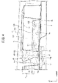
Figure 1 is a plan view of a floor panel of a vehicle provided with electrical equipment according to an embodiment of the present invention. -
Figure 2 is a diagram illustrating a cross member of the vehicle provided with the electrical equipment according to the embodiment of the present invention viewed from behind. -
Figure 3 is a plan view of a battery pack and surrounding floor panel of the vehicle provided with the electrical equipment according to the embodiment of the present invention. -
Figure 4 is a diagram illustrating the battery pack of the vehicle provided with the electrical equipment according to the embodiment of the present invention viewed from the left. -
Figure 5 is a plan view of a battery and the surrounding floor panel of the vehicle provided with the electrical equipment according to the embodiment of the present invention. -
Figure 6 is a diagram illustrating the battery of the vehicle provided with the electrical equipment according to the embodiment of the present invention viewed from the left. -
Figure 7 is a diagram illustrating the battery pack of the vehicle provided with the electrical equipment according to the embodiment of the present invention viewed from below. -
Figure 8 is a diagram illustrating the battery of the vehicle provided with the electrical equipment according to the embodiment of the present invention viewed from forward. -
Figure 9 is a cross-sectional view ofFigure 3 viewing from a IX-IX arrow direction. -
Figure 10 is a diagram illustrating the battery pack of the vehicle provided with the electrical equipment according to the embodiment of the present invention viewed from forward. - An electrical equipment according to an embodiment of the present invention is installed on a vehicle, the vehicle including: a cross member with a hole portion, the cross member extending in a vehicle width direction above a floor panel; and a first wire harness attached to the cross member so as to be located above the hole portion, the first wire harness extending in the vehicle width direction, the electrical equipment including: an electric component installed on the floor panel; and a cover member installed on the floor panel so as to cover the electric component, wherein the cover member includes a side wall facing the first wire harness, and a bulging part bulging from a wall surface of the side wall toward the first wire harness, and the bulging part covers the first wire harness from above.
- Thus, with the electrical equipment according to the present invention, it is possible to prevent, when an impact is applied to a vehicle from a vehicle width direction, an impact caused by deformation of a wire harness from being applied above a floor panel.
- Hereinafter, an electrical equipment according to an embodiment of the present invention will be described with reference to drawings.
-
Figure 1 to Figure 10 are diagrams illustrating a protective structure for an electrical equipment according to an embodiment of the present invention. InFigure 1 to Figure 10 , up-down, front-rear and left-right directions are defined such that a front-rear direction of a vehicle on which a battery pack is mounted is the front-rear direction, a left-right direction of the vehicle (vehicle width direction) is the left-right direction and an up-down direction of the vehicle (vehicle height direction) is the up-down direction. - First, a configuration will be described.
- In
Figure 1 , avehicle 1 includes afloor panel 2. A left-side side sill 3L is provided at a left end portion of thefloor panel 2 and the left-side side sill 3L extends in the front-rear direction along thefloor panel 2. A right-side side sill 3R is provided at a right end portion of thefloor panel 2 and the right-side side sill 3R extends in the front-rear direction along thefloor panel 2. - A
floor tunnel 4 is provided in a center portion of thefloor panel 2 in a vehicle width direction and thefloor tunnel 4 bulges upward from thefloor panel 2. - A front-
side cross member 5 and a rear-side cross member 6 are attached between thefloor tunnel 4 and the left-side side sill 3L, and the front-side cross member 5 and the rear-side cross member 6 extend in the vehicle width direction spaced apart in the front-rear direction. - A front-side cross member 7 and a rear-
side cross member 8 are attached between thefloor tunnel 4 and the right-side side sill 3R, and the front-side cross member 7 and the rear-side cross member 8 extend in the vehicle width direction spaced apart in the front-rear direction. - As shown in
Figure 2 , part of awire harness 9 is attached to the front-side cross member 5 and thewire harness 9 extends in the vehicle width direction. More specifically, as shown inFigure 1 , thewire harness 9 extends in the front-rear direction along the right-side side sill 3R, branches from a center portion in a direction in which the right-side side sill 3R extends and extends to thefloor tunnel 4 along the front-side cross member 7. - The
wire harness 9 extends in the vehicle width direction from thefloor tunnel 4 along the front-side cross member 5 and then extends in the front-rear direction along the left-side side sill 3L. The front-side cross member 5 of the present embodiment constitutes a cross member and thewire harness 9 constitutes a first wire harness. - As shown in
Figure 2 , the front-side cross member 5 includes ahole portion 5a formed at the center portion in the vehicle width direction. Thehole portion 5a is intended to pass a vehicle-mounted component to be installed in the front-rear direction across the front-side cross member 5. For example, a duct of an air conditioner to be installed in front of the front-side cross member 5 is passed through thehole portion 5a and the duct to be passed through thehole portion 5a extends behind the front-side cross member 5. - The front-
side cross member 5 includes a band-shaped member 10A. The band-shaped member 10A is provided above thehole portion 5a and configured to fix the center portion of thewire harness 9 in the vehicle width direction to the front-side cross member 5. - The front-
side cross member 5 includes band-shaped members shaped members shaped member 10A and at left and right end portions of the front-side cross member 5 in the vehicle width direction with respect to the band-shapedmember 10A and configured to fix the left and right end portions of thewire harness 9 to the front-side cross member 5. - That is, the band-
shaped member 10B is located on the left end side in the vehicle width direction with respect to the band-shaped member 10A and the band-shaped member 10C is located on the right end side in the vehicle width direction with respect to the band-shaped member 10A. - Here, the center portion of the
wire harness 9 in the vehicle width direction and the left and right end portions in the vehicle width direction are based on the length of the front-side cross member 5 in the vehicle width direction, and mean the center portion of the region of thewire harness 9 routed in the vehicle width direction of the front-side cross member 5 and the left and right end portions in the vehicle width direction. - The band-
shaped member 10A of the present embodiment constitutes a first mounting part, and the band-shaped members - As shown in
Figure 1 ,Figure 3 andFigure 4 , abattery pack 11 as an electrical apparatus is installed on anupper surface 2a of thefloor panel 2 and thebattery pack 11 is installed in a space between an assistant driver's seat (not shown) and thefloor panel 2. Note that thebattery pack 11 may also be installed in a space between the driver's seat (not shown) and thefloor panel 2. - Since the
battery pack 11 is installed between the assistant driver's seat and thefloor panel 2, thebattery pack 11 can be installed in a vehicle room in a cooler environment than in an engine room, and performance of abattery 12, which will be described later, can be extracted more easily. - In addition to this, it is possible to prevent the space of a baggage compartment from being blocked by the
battery pack 11, improve installation performance of thebattery pack 11, and moreover eliminate the need for installing thebattery pack 11 in the engine room, and thus reduce the size of the engine room. - As shown in
Figure 1 , in a plan view of thevehicle 1, thebattery pack 11 is located among the left-side side sill 3L, thefloor tunnel 4, the front-side cross member 5 and the rear-side cross member 6. - As shown in
Figure 5 andFigure 6 , thebattery pack 11 includes thebattery 12 as an electric component. Thebattery 12 includes a plurality of battery modules (not shown), a battery holder that accommodates the plurality of battery modules and protect the battery modules and asubstrate part 23 provided on an upper surface of the battery holder. - As shown in
Figure 5 andFigure 7 , thebattery 12 is provided with a plurality offixing pieces fixing pieces battery 12 in the vehicle width direction (outward to the left and right). - As shown in
Figure 6 , thefloor panel 2 is provided with abracket 14 and thebracket 14 is provided with fixingpieces Figure 5 ). - The fixing
pieces bracket 14 and are located at positions higher than theupper surface 2a of thefloor panel 2. - The
bracket 14 is provided with fixing pieces 14C and 14D (seeFigure 5 ). The fixing pieces 14C and 14D protrude upward from a left end portion of thebracket 14 and are located at positions higher than theupper surface 2a of thefloor panel 2. The fixingpieces - The fixing
pieces battery 12 are fixed to the fixingpieces pieces battery 12 are fixed to the fixing pieces 14C and 14D with abolt 51A. The fixingpieces - Thus, the
battery 12 is fixed to thefloor panel 2 via thebracket 14, to be upward away from thefloor panel 2 by thebracket 14. The fixingpieces - As shown with virtual lines in
Figure 5 andFigure 8 ,terminal parts front surface 12a of thebattery 12, and theterminal parts vehicle 1 are installed side by side in the vehicle width direction. The vehicle width direction is a direction L in which theterminal parts terminal parts - The
terminal parts pieces battery 12 in the height direction (seeFigure 6 ). Note that thewire harness 9 is omitted inFigure 5 . - As shown in
Figure 9 , theterminal parts front surface 12a of thebattery 12 and extend in the up-down direction. Note that theterminal parts terminal part 13A of the present embodiment constitutes a first terminal part and theterminal part 13B constitutes a second terminal part. - As shown in
Figure 6 , thesubstrate part 23 is provided above theterminal parts substrate part 23 is a control substrate configured to detect a remaining capacity of the battery module and control charging/discharging or the like. - As shown in
Figure 5 , anopening portion 2b is formed on thefloor panel 2. Theopening portion 2b is located on thefloor tunnel 4 side with respect to theterminal parts vehicle 1. - The
terminal part 13B is installed at a position farther from theopening portion 2b in the arrangement direction L of the terminal parts than theterminal part 13A. - As shown in
Figure 8 , wire harnesses 21 and 22 are connected to thebattery pack 11. The wire harnesses 21 and 22 are introduced into thecover member 15 through theopening portion 2b from below thefloor panel 2, extends above the floor panel 2 (i.e., within the cover member 15) in the arrangement direction L of the terminal parts, and are connected to theterminal part 13A and theterminal part 13B viaconnectors 21C and 22C provided at end portions of the wire harnesses 21 and 22, respectively. - The wire harnesses 21 and 22 are routed passing through the
floor tunnel 4 below thefloor panel 2 and the other end portion thereof is connected to another electric component such as an auxiliary machine. Thus, electric power of thebattery 12 is supplied to the other electric component such as an auxiliary machine by the wire harnesses 21 and 22. The wire harnesses 21 and 22 of the present embodiment constitute a second wire harness. - As shown in
Figure 4 andFigure 9 , thebattery pack 11 includes acover member 15. Thecover member 15 includes aceiling wall 15A, and afront wall 15B, a rear wall 15C, aleft side wall 15D and aright side wall 15E extending downward from theceiling wall 15A. - The
ceiling wall 15A covers above theopening portion 2b, the upper surface of thebattery 12 and the wire harnesses 21 and 22 from above. Thefront wall 15B covers thefront surface 12a of thebattery 12 and the wire harnesses 21 and 22, and the rear wall 15C, theleft side wall 15D and theright side wall 15E cover the rear surface, the left side surface and the right side surface of thebattery 12. - That is, the
opening portion 2b is located inside thefront wall 15B, the rear wall 15C, theleft side wall 15D and theright side wall 15E, and is covered with thecover member 15. Thefront wall 15B, the rear wall 15C, theleft side wall 15D and theright side wall 15E of the present embodiment constitute side walls. - The
front wall 15B of thecover member 15 faces thewire harness 9 in the front-rear direction, and thewire harness 9 is routed along thefront wall 15B in the vehicle width direction (seeFigure 3 ). - A
bottom end portion 15u of thefront wall 15B, the rear wall 15C, theleft side wall 15D and theright side wall 15E is close to thefloor panel 2 and is located at the same height position as the position of anundersurface 12u of the battery 12 (seeFigure 9 ). The lengths (heights) of thefront wall 15B, the rear wall 15C, theleft side wall 15D and theright side wall 15E in the up-down direction are identical. - The
front surface 12a of thebattery 12 of the present embodiment constitutes a side surface of the electric component and thefront wall 15B of thecover member 15 constitutes a side wall of the cover member. - As shown in
Figure 3 andFigure 7 , thecover member 15 is provided with coveringparts part 15F protrudes outward (rightward) from theright side wall 15E of thecover member 15 and covers the fixingpieces battery 12 from above and from the left (seeFigure 7 andFigure 10 ). - The covering
part 15G protrudes outward (leftward) from theleft side wall 15D of thecover member 15 and covers the fixingpieces battery 12 from above and from the left (seeFigure 4 andFigure 7 ). - As shown in
Figure 9 , thefront wall 15B of thecover member 15 facing thefront surface 12a of thebattery 12 in the front-rear direction is provided with a bulging part 16 (seeFigure 3 ,Figure 4 andFigure 7 ). - The bulging
part 16 is located above thebottom end portion 15u of thefront wall 15B and bulges in a direction away from thefront surface 12a of thebattery 12 with respect to thewall surface 15a of thefront wall 15B. - As shown in
Figure 4 andFigure 9 , the bulgingpart 16 includes aninclined part 16t. Theinclined part 16t is inclined so as to be further away from thefront surface 12a of thebattery 12 as it extends upward from thewall surface 15a of thefront wall 15B. In the bulgingpart 16, adistal end portion 16a in the bulging direction located above theinclined part 16t is furthest forward away from thefront surface 12a of thebattery 12. - The
terminal parts part 16 and face the bulgingpart 16 in the front-rear direction. - The
terminal parts distal end portion 16a in the bulging direction of the bulgingpart 16 which is furthest forward away from thebattery 12. - As shown in
Figure 9 , the bulgingpart 16 bulges from thewall surface 15a of thefront wall 15B of thecover member 15 on thewire harness 9 side (toward the wire harness 9) and covers thewire harness 9 from above. - The bulging
part 16 is located above the band-shapedmember 10A. As shown inFigure 1 , the bulgingpart 16 overlaps the band-shapedmember 10A in a plan view of thevehicle 1. In other words, the bulgingpart 16 is provided alongside the band-shapedmember 10A in the up-down direction. - Since the
terminal part 13B is installed at a position farther from theopening portion 2b than theterminal part 13A in the arrangement direction L of the terminal parts, the routing length of thewire harness 22 in thecover member 15 is longer than the routing length of thewire harness 21. - As shown in
Figure 9 , thewire harness 22 is installed in aspace portion 17 formed by the bulgingpart 16 inside thecover member 15 and extends in the arrangement direction L of the terminal parts along theinclined part 16t. - Inside the
cover member 15, thewire harness 21 is installed closer to thefront surface 12a side of thebattery 12 than thewire harness 22 installed in thespace portion 17 formed by the bulgingpart 16. - As shown in
Figure 8 , since thebattery 12 is formed to have a longer length in the vehicle width direction (lateral direction) than a length in the up-down direction (longitudinal direction), the wire harnesses 21 and 22 are routed inside thecover member 15 so as to have a longer routing length in the arrangement direction L of the terminal parts than a routing length in the up-down direction. - More specifically, the wire harnesses 21 and 22 include lower
wire harness parts wire harness parts - The lower
wire harness parts floor panel 2 from theopening portion 2b of thefloor panel 2. - The upper
wire harness parts wire harness parts terminal parts - In the wire harnesses 21 and 22 of the present embodiment, the upper
wire harness parts cover member 15 so as to be longer than the lowerwire harness parts - As shown in
Figure 10 , the bulgingpart 16 is formed to have a length L1 in the arrangement direction L of the terminal parts (seeFigure 3 ) longer than a routing length L2 of the wire harnesses 21 and 22 in the arrangement direction L of the terminal parts inside thecover member 15. - The bulging
part 16 is formed to have a length T1 in the up-down direction longer than a length (height) T2 of the upperwire harness parts wire harness part 21B or the upperwire harness part 22B in the up-down direction inside thecover member 15 is a length (height) from an upper end of the upperwire harness parts wire harness part 21B or the upperwire harness part 22B located at the lowest position. - As shown in
Figure 9 , in a side view of thebattery 12, that is, when thebattery 12 is viewed from the vehicle width direction, the bulgingpart 16 is installed at a position that overlaps with the upperwire harness part 22B. That is, the bulgingpart 16 and the upperwire harness part 22B overlap each other in the front-rear direction. - Note that the lower
wire harness parts wire harness parts part 16 in the side view of thebattery 12 may be installed at a position that overlaps with the lowerwire harness part 22A. - As shown in
Figure 9 , anotch portion 12b is formed on thefront surface 12a of thebattery 12 and thenotch portion 12b is located below theterminal parts - A
space portion 18 surrounded by thenotch portion 12b is formed inside thecover member 15. - As shown in
Figure 7 andFigure 9 , aradiation fin 12c is formed in thenotch portion 12b and theradiation fin 12c is installed in thespace portion 18. - Next, effects of the
battery pack 11 of the present embodiment will be described. - The
battery pack 11 of the present embodiment is installed on thevehicle 1, and thevehicle 1 includes the front-side cross member 5 with thehole portion 5a, which is installed above thefloor panel 2 so as to extend in the vehicle width direction, and thewire harness 9 attached to the front-side cross member 5 so as to be located at a position above thehole portion 5a and extending in the vehicle width direction. - The
battery pack 11 is provided with thebattery 12 installed on thefloor panel 2 and thecover member 15 installed on thefloor panel 2 so as to cover thebattery 12. - The
cover member 15 includes thefront wall 15B facing thewire harness 9 and the bulgingpart 16 provided on thefront wall 15B and bulges from thewall surface 15a of thefront wall 15B to thewire harness 9 side, and the bulgingpart 16 covers thewire harness 9 from above. In other words, in a plan view of the vehicle, the bulgingpart 16 covers at least a part of thewire harness 9. - When an impact is applied to the
vehicle 1 from the vehicle width direction and thewire harness 9 deforms upward toward the floor panel 2 (see thewire harness 9L inFigure 2 ), it is possible to cause thewire harness 9 to collide with the bulgingpart 16 and prevent thewire harness 9 from deforming above thefloor panel 2. - This makes it possible to prevent the
wire harness 9 from colliding with the assistant driver's seat above thefloor panel 2 and prevent an impact from being applied to the assistant driver's seat. - It is also possible to use the bulging
part 16 of thecover member 15 to prevent thewire harness 9 from deforming upward, thereby eliminate the need for providing a new restricting member for restricting upward deformation of thewire harness 9, prevent an increase in the number of parts of thevehicle 1 and an increase in manufacturing man-hours and thereby reduce the manufacturing cost of thevehicle 1. - The
battery pack 11 of the present embodiment includes the front-side cross member 5 provided above thehole portion 5a, the band-shapedmember 10A configured to attach thewire harness 9 to the front-side cross member 5 and the band-shapedmembers member 10A and configured to attach thewire harness 9 to the front-side cross member 5. - When the band-shaped
member 10A is provided at the center portion of the front-side cross member 5 in the vehicle width direction and the band-shapedmembers member 10A and at left and right end portions of the front-side cross member 5 in the vehicle width direction, it is possible to cause, when an impact is applied to thevehicle 1 from the vehicle width direction, thewire harness 9 to deform so that the center portion of thewire harness 9 in the vehicle width direction becomes the top of a mountain and set thewire harness 9 so as to collide with the bulgingpart 16. - This makes it possible to more effectively prevent the
wire harness 9 from deforming above thefloor panel 2. As a result, it is possible to more effectively prevent thewire harness 9 from colliding with the assistant driver's seat above thefloor panel 2 and more effectively prevent an impact from being applied to the assistant driver's seat. - According to the
battery pack 11 of the present embodiment, thefloor panel 2 includes theopening portion 2b configured to route the wire harnesses 21 and 22 from below thefloor panel 2 into thecover member 15. - The
battery 12 includes theterminal parts front surface 12a facing thefront wall 15B of thecover member 15, and the wire harnesses 21 and 22 are routed to thespace portion 17 formed by the bulgingpart 16. - Using the
space portion 17 formed by the bulgingpart 16 in this way, the wire harnesses 21 and 22 can be routed into thecover member 15. This makes it possible not only to improve routing performance of the wire harnesses 21 and 22 but also to route more wire harnesses using thecover member 15. - The
terminal part 13A, theterminal part 13B and theopening portion 2b are arranged in the arrangement direction L of the terminal parts in a plan view of thevehicle 1, and when the wire harnesses 21 and 22 pass through theopening portion 2b from below thefloor panel 2 and extend above thefloor panel 2 and in the arrangement direction L of the terminal parts, and are connected to theterminal parts cover member 15 and route them inside thecover member 15. - As a result, it is possible to prevent an excessive load from being applied to the wire harnesses 21 and 22 and protect the wire harnesses 21 and 22.
- Note that although the terminal parts of the present embodiment are constructed of the
terminal parts - Although the
wire harness 22 is routed in thespace portion 17 of the bulgingpart 16, both wire harnesses 21 and 22 may be routed in thespace portion 17 of the bulgingpart 16. - The electric component is not limited to the
battery 12 but is applicable to, for example, a DC-DC converter. However, the electric component is not limited to a battery or a DC-DC converter, but it can be any electrical part mounted on thevehicle 1. - Although an embodiment of the present invention has been disclosed, it is obvious that changes can be added by those skilled in the art without departing from the scope of the present invention. All such modifications and equivalents are intended to be included in the following claims.
- 1...vehicle, 2...floor panel, 2b...opening, 5...front-side cross member, 5a...hole portion, 9...wire harness (first wire harness), 10A...band-shaped member (first mounting part), 10B, 10C...band-shaped member (second mounting part), 11...battery pack (electrical equipment), 12...battery (electric component), 12a...front surface (side surface of electric component), 13A, 13B...terminal part, 15...cover member, 15a...wall surface (wall surface of side wall of cover member), 15B...front wall (side wall of cover member), 16...bulging part, 17...space portion (space portion formed by bulging part), 21, 22...wire harness (second wire harness)
Claims (3)
- An electrical equipment (11) installed on a vehicle (1), the vehicle (1) including:a cross member (5) with a hole portion (5a), the cross member extending in a vehicle width direction above a floor panel (2); anda first wire harness (9) attached to the cross member (5) so as to be located above the hole portion (5a), the first wire harness extending in the vehicle width direction,the electrical equipment (11) comprising:an electric component (12) installed on the floor panel (2); anda cover member (15) installed on the floor panel (2) so as to cover the electric component (12), whereinthe cover member (15) includes a side wall (15B) facing the first wire harness (9), and a bulging part (16) bulging from a wall surface (15a) of the side wall (15B) toward the first wire harness (9), andthe bulging part (16) covers the first wire harness (9) from above.
- The electrical equipment according to claim 1, whereinthe cross member (5) includes a first mounting part (10A) to fix the first wire harness (9) to the cross member (5), and a second mounting part (10B, 10C) to fix the first wire harness (9) to the cross member (5), the first mounting part being located above the hole portion (5a), the second mounting part being located below the first mounting part, andthe bulging part (16) is located above the first mounting part (10A), and overlaps with the first mounting part (10A) in a plan view of the vehicle (1).
- The electrical equipment according to claim 1 or 2, whereinthe vehicle (1) includes a second wire harness (21, 22),the floor panel (2) is formed with an opening portion (2b) through which the second wire harness (21, 22) is introduced into the cover member (15),the electric component (12) includes, at a side surface (12a) thereof facing the side wall (15B) of the cover member (15), a terminal part (13A, 13B) to which the second wire harness (21, 22) is connected, andthe second wire harness (21, 22) is routed to a space portion (17) defined by the bulging part (16).
Applications Claiming Priority (1)
| Application Number | Priority Date | Filing Date | Title |
|---|---|---|---|
| JP2021030107A JP7521456B2 (en) | 2021-02-26 | 2021-02-26 | Electrical Equipment |
Publications (2)
| Publication Number | Publication Date |
|---|---|
| EP4049899A1 true EP4049899A1 (en) | 2022-08-31 |
| EP4049899B1 EP4049899B1 (en) | 2025-06-25 |
Family
ID=80446567
Family Applications (1)
| Application Number | Title | Priority Date | Filing Date |
|---|---|---|---|
| EP22155470.2A Active EP4049899B1 (en) | 2021-02-26 | 2022-02-07 | Electrical equipment |
Country Status (2)
| Country | Link |
|---|---|
| EP (1) | EP4049899B1 (en) |
| JP (1) | JP7521456B2 (en) |
Cited By (1)
| Publication number | Priority date | Publication date | Assignee | Title |
|---|---|---|---|---|
| EP4497637A1 (en) * | 2023-07-25 | 2025-01-29 | Ampere SAS | Arrangement for a motor vehicle |
Citations (5)
| Publication number | Priority date | Publication date | Assignee | Title |
|---|---|---|---|---|
| WO2012028927A2 (en) * | 2010-08-31 | 2012-03-08 | Toyota Jidosha Kasbushiki Kaisha | Electricity storage device and vehicle |
| EP2685524A1 (en) * | 2012-07-13 | 2014-01-15 | Mitsubishi Jidosha Kogyo Kabushiki Kaisha | Battery pack of vehicle |
| DE112014006229T5 (en) * | 2014-01-22 | 2016-11-03 | Toyota Jidosha Kabushiki Kaisha | motor vehicle |
| US20180086192A1 (en) * | 2016-09-27 | 2018-03-29 | Honda Motor Co.,Ltd. | Vehicle body lower structure |
| JP2019206303A (en) | 2018-05-30 | 2019-12-05 | スズキ株式会社 | Vehicle lower part structure |
Family Cites Families (2)
| Publication number | Priority date | Publication date | Assignee | Title |
|---|---|---|---|---|
| JP4686166B2 (en) | 2004-10-22 | 2011-05-18 | 矢崎総業株式会社 | Electric cable routing structure of resin cover for battery |
| JP5567979B2 (en) | 2010-10-22 | 2014-08-06 | 住友電装株式会社 | Wiring structure of automotive harness |
-
2021
- 2021-02-26 JP JP2021030107A patent/JP7521456B2/en active Active
-
2022
- 2022-02-07 EP EP22155470.2A patent/EP4049899B1/en active Active
Patent Citations (5)
| Publication number | Priority date | Publication date | Assignee | Title |
|---|---|---|---|---|
| WO2012028927A2 (en) * | 2010-08-31 | 2012-03-08 | Toyota Jidosha Kasbushiki Kaisha | Electricity storage device and vehicle |
| EP2685524A1 (en) * | 2012-07-13 | 2014-01-15 | Mitsubishi Jidosha Kogyo Kabushiki Kaisha | Battery pack of vehicle |
| DE112014006229T5 (en) * | 2014-01-22 | 2016-11-03 | Toyota Jidosha Kabushiki Kaisha | motor vehicle |
| US20180086192A1 (en) * | 2016-09-27 | 2018-03-29 | Honda Motor Co.,Ltd. | Vehicle body lower structure |
| JP2019206303A (en) | 2018-05-30 | 2019-12-05 | スズキ株式会社 | Vehicle lower part structure |
Cited By (2)
| Publication number | Priority date | Publication date | Assignee | Title |
|---|---|---|---|---|
| EP4497637A1 (en) * | 2023-07-25 | 2025-01-29 | Ampere SAS | Arrangement for a motor vehicle |
| FR3151553A1 (en) * | 2023-07-25 | 2025-01-31 | Renault S.A.S | Arrangement for motor vehicle. |
Also Published As
| Publication number | Publication date |
|---|---|
| JP7521456B2 (en) | 2024-07-24 |
| EP4049899B1 (en) | 2025-06-25 |
| JP2022131254A (en) | 2022-09-07 |
Similar Documents
| Publication | Publication Date | Title |
|---|---|---|
| CN110071237B (en) | Battery unit for vehicle | |
| CN114537118B (en) | Battery pack-mounted vehicle | |
| KR101523481B1 (en) | Wiring protective cover structure for electric vehicle | |
| JP6706507B2 (en) | vehicle | |
| CN102555754B (en) | The Wiring harness arrangement structure of vehicle | |
| CN104349923B (en) | Electric vehicle | |
| US10220723B2 (en) | Fuel cell vehicle | |
| JPWO2017110138A1 (en) | High voltage control equipment unit mounting structure | |
| CN103842194A (en) | Electric vehicle | |
| CN110299483A (en) | Battery pack | |
| US11548362B2 (en) | Vehicle battery unit | |
| EP4108491A1 (en) | Vehicle front portion structure | |
| CN106356483A (en) | Battery unit for a vehicle | |
| JP2020040577A (en) | vehicle | |
| EP4049899A1 (en) | Electrical equipment | |
| EP4049872A1 (en) | Protective structure for electric component | |
| EP3782835B1 (en) | Vehicle battery pack | |
| CN114987179B (en) | Vehicle-mounted battery package | |
| JP2012197019A (en) | Routing structure of high voltage cable | |
| EP4049900B1 (en) | Protection structure of wire harnesses | |
| CN120511420A (en) | Battery housing and electric vehicle structure | |
| JP2019111837A (en) | Loading structure of power control unit | |
| EP3772425B1 (en) | Vehicle battery pack | |
| US12407154B2 (en) | Protector and wire harness | |
| EP3798034B1 (en) | Electrical component support structure |
Legal Events
| Date | Code | Title | Description |
|---|---|---|---|
| PUAI | Public reference made under article 153(3) epc to a published international application that has entered the european phase |
Free format text: ORIGINAL CODE: 0009012 |
|
| STAA | Information on the status of an ep patent application or granted ep patent |
Free format text: STATUS: REQUEST FOR EXAMINATION WAS MADE |
|
| 17P | Request for examination filed |
Effective date: 20220207 |
|
| AK | Designated contracting states |
Kind code of ref document: A1 Designated state(s): AL AT BE BG CH CY CZ DE DK EE ES FI FR GB GR HR HU IE IS IT LI LT LU LV MC MK MT NL NO PL PT RO RS SE SI SK SM TR |
|
| GRAP | Despatch of communication of intention to grant a patent |
Free format text: ORIGINAL CODE: EPIDOSNIGR1 |
|
| STAA | Information on the status of an ep patent application or granted ep patent |
Free format text: STATUS: GRANT OF PATENT IS INTENDED |
|
| INTG | Intention to grant announced |
Effective date: 20250314 |
|
| GRAS | Grant fee paid |
Free format text: ORIGINAL CODE: EPIDOSNIGR3 |
|
| GRAA | (expected) grant |
Free format text: ORIGINAL CODE: 0009210 |
|
| STAA | Information on the status of an ep patent application or granted ep patent |
Free format text: STATUS: THE PATENT HAS BEEN GRANTED |
|
| AK | Designated contracting states |
Kind code of ref document: B1 Designated state(s): AL AT BE BG CH CY CZ DE DK EE ES FI FR GB GR HR HU IE IS IT LI LT LU LV MC MK MT NL NO PL PT RO RS SE SI SK SM TR |
|
| REG | Reference to a national code |
Ref country code: GB Ref legal event code: FG4D |
|
| REG | Reference to a national code |
Ref country code: CH Ref legal event code: EP |
|
| REG | Reference to a national code |
Ref country code: CH Ref legal event code: EP |
|
| REG | Reference to a national code |
Ref country code: IE Ref legal event code: FG4D |
|
| REG | Reference to a national code |
Ref country code: DE Ref legal event code: R096 Ref document number: 602022016268 Country of ref document: DE |
|
| PG25 | Lapsed in a contracting state [announced via postgrant information from national office to epo] |
Ref country code: FI Free format text: LAPSE BECAUSE OF FAILURE TO SUBMIT A TRANSLATION OF THE DESCRIPTION OR TO PAY THE FEE WITHIN THE PRESCRIBED TIME-LIMIT Effective date: 20250625 |
|
| REG | Reference to a national code |
Ref country code: LT Ref legal event code: MG9D |
|
| PG25 | Lapsed in a contracting state [announced via postgrant information from national office to epo] |
Ref country code: NO Free format text: LAPSE BECAUSE OF FAILURE TO SUBMIT A TRANSLATION OF THE DESCRIPTION OR TO PAY THE FEE WITHIN THE PRESCRIBED TIME-LIMIT Effective date: 20250925 Ref country code: GR Free format text: LAPSE BECAUSE OF FAILURE TO SUBMIT A TRANSLATION OF THE DESCRIPTION OR TO PAY THE FEE WITHIN THE PRESCRIBED TIME-LIMIT Effective date: 20250926 |
|
| PG25 | Lapsed in a contracting state [announced via postgrant information from national office to epo] |
Ref country code: BG Free format text: LAPSE BECAUSE OF FAILURE TO SUBMIT A TRANSLATION OF THE DESCRIPTION OR TO PAY THE FEE WITHIN THE PRESCRIBED TIME-LIMIT Effective date: 20250625 |
|
| PG25 | Lapsed in a contracting state [announced via postgrant information from national office to epo] |
Ref country code: HR Free format text: LAPSE BECAUSE OF FAILURE TO SUBMIT A TRANSLATION OF THE DESCRIPTION OR TO PAY THE FEE WITHIN THE PRESCRIBED TIME-LIMIT Effective date: 20250625 |
|
| PG25 | Lapsed in a contracting state [announced via postgrant information from national office to epo] |
Ref country code: RS Free format text: LAPSE BECAUSE OF FAILURE TO SUBMIT A TRANSLATION OF THE DESCRIPTION OR TO PAY THE FEE WITHIN THE PRESCRIBED TIME-LIMIT Effective date: 20250925 |
|
| PG25 | Lapsed in a contracting state [announced via postgrant information from national office to epo] |
Ref country code: LV Free format text: LAPSE BECAUSE OF FAILURE TO SUBMIT A TRANSLATION OF THE DESCRIPTION OR TO PAY THE FEE WITHIN THE PRESCRIBED TIME-LIMIT Effective date: 20250625 |
|
| REG | Reference to a national code |
Ref country code: NL Ref legal event code: MP Effective date: 20250625 |
|
| PG25 | Lapsed in a contracting state [announced via postgrant information from national office to epo] |
Ref country code: NL Free format text: LAPSE BECAUSE OF FAILURE TO SUBMIT A TRANSLATION OF THE DESCRIPTION OR TO PAY THE FEE WITHIN THE PRESCRIBED TIME-LIMIT Effective date: 20250625 |
|
| PG25 | Lapsed in a contracting state [announced via postgrant information from national office to epo] |
Ref country code: PT Free format text: LAPSE BECAUSE OF FAILURE TO SUBMIT A TRANSLATION OF THE DESCRIPTION OR TO PAY THE FEE WITHIN THE PRESCRIBED TIME-LIMIT Effective date: 20251027 |
|
| REG | Reference to a national code |
Ref country code: AT Ref legal event code: MK05 Ref document number: 1806167 Country of ref document: AT Kind code of ref document: T Effective date: 20250625 |
|
| PG25 | Lapsed in a contracting state [announced via postgrant information from national office to epo] |
Ref country code: IS Free format text: LAPSE BECAUSE OF FAILURE TO SUBMIT A TRANSLATION OF THE DESCRIPTION OR TO PAY THE FEE WITHIN THE PRESCRIBED TIME-LIMIT Effective date: 20251025 |
|
| PG25 | Lapsed in a contracting state [announced via postgrant information from national office to epo] |
Ref country code: AT Free format text: LAPSE BECAUSE OF FAILURE TO SUBMIT A TRANSLATION OF THE DESCRIPTION OR TO PAY THE FEE WITHIN THE PRESCRIBED TIME-LIMIT Effective date: 20250625 Ref country code: SM Free format text: LAPSE BECAUSE OF FAILURE TO SUBMIT A TRANSLATION OF THE DESCRIPTION OR TO PAY THE FEE WITHIN THE PRESCRIBED TIME-LIMIT Effective date: 20250625 |
|
| PGFP | Annual fee paid to national office [announced via postgrant information from national office to epo] |
Ref country code: FR Payment date: 20251231 Year of fee payment: 5 |
|
| PG25 | Lapsed in a contracting state [announced via postgrant information from national office to epo] |
Ref country code: CZ Free format text: LAPSE BECAUSE OF FAILURE TO SUBMIT A TRANSLATION OF THE DESCRIPTION OR TO PAY THE FEE WITHIN THE PRESCRIBED TIME-LIMIT Effective date: 20250625 |
|
| PG25 | Lapsed in a contracting state [announced via postgrant information from national office to epo] |
Ref country code: PL Free format text: LAPSE BECAUSE OF FAILURE TO SUBMIT A TRANSLATION OF THE DESCRIPTION OR TO PAY THE FEE WITHIN THE PRESCRIBED TIME-LIMIT Effective date: 20250625 |
|
| PG25 | Lapsed in a contracting state [announced via postgrant information from national office to epo] |
Ref country code: EE Free format text: LAPSE BECAUSE OF FAILURE TO SUBMIT A TRANSLATION OF THE DESCRIPTION OR TO PAY THE FEE WITHIN THE PRESCRIBED TIME-LIMIT Effective date: 20250625 |
|
| PG25 | Lapsed in a contracting state [announced via postgrant information from national office to epo] |
Ref country code: SK Free format text: LAPSE BECAUSE OF FAILURE TO SUBMIT A TRANSLATION OF THE DESCRIPTION OR TO PAY THE FEE WITHIN THE PRESCRIBED TIME-LIMIT Effective date: 20250625 |
|
| PG25 | Lapsed in a contracting state [announced via postgrant information from national office to epo] |
Ref country code: ES Free format text: LAPSE BECAUSE OF FAILURE TO SUBMIT A TRANSLATION OF THE DESCRIPTION OR TO PAY THE FEE WITHIN THE PRESCRIBED TIME-LIMIT Effective date: 20250625 |
|
| PG25 | Lapsed in a contracting state [announced via postgrant information from national office to epo] |
Ref country code: DK Free format text: LAPSE BECAUSE OF FAILURE TO SUBMIT A TRANSLATION OF THE DESCRIPTION OR TO PAY THE FEE WITHIN THE PRESCRIBED TIME-LIMIT Effective date: 20250625 |
|
| PGFP | Annual fee paid to national office [announced via postgrant information from national office to epo] |
Ref country code: DE Payment date: 20251230 Year of fee payment: 5 |
|
| PG25 | Lapsed in a contracting state [announced via postgrant information from national office to epo] |
Ref country code: IT Free format text: LAPSE BECAUSE OF FAILURE TO SUBMIT A TRANSLATION OF THE DESCRIPTION OR TO PAY THE FEE WITHIN THE PRESCRIBED TIME-LIMIT Effective date: 20250625 |
|
| PLBE | No opposition filed within time limit |
Free format text: ORIGINAL CODE: 0009261 |
|
| STAA | Information on the status of an ep patent application or granted ep patent |
Free format text: STATUS: NO OPPOSITION FILED WITHIN TIME LIMIT |