EP4049892A1 - Seat suspension mechanism - Google Patents
Seat suspension mechanism Download PDFInfo
- Publication number
- EP4049892A1 EP4049892A1 EP20878899.2A EP20878899A EP4049892A1 EP 4049892 A1 EP4049892 A1 EP 4049892A1 EP 20878899 A EP20878899 A EP 20878899A EP 4049892 A1 EP4049892 A1 EP 4049892A1
- Authority
- EP
- European Patent Office
- Prior art keywords
- spring
- frame
- link
- link mechanism
- intermediate frame
- Prior art date
- Legal status (The legal status is an assumption and is not a legal conclusion. Google has not performed a legal analysis and makes no representation as to the accuracy of the status listed.)
- Granted
Links
Images







Classifications
-
- B—PERFORMING OPERATIONS; TRANSPORTING
- B60—VEHICLES IN GENERAL
- B60N—SEATS SPECIALLY ADAPTED FOR VEHICLES; VEHICLE PASSENGER ACCOMMODATION NOT OTHERWISE PROVIDED FOR
- B60N2/00—Seats specially adapted for vehicles; Arrangement or mounting of seats in vehicles
- B60N2/50—Seat suspension devices
- B60N2/502—Seat suspension devices attached to the base of the seat
-
- B—PERFORMING OPERATIONS; TRANSPORTING
- B60—VEHICLES IN GENERAL
- B60N—SEATS SPECIALLY ADAPTED FOR VEHICLES; VEHICLE PASSENGER ACCOMMODATION NOT OTHERWISE PROVIDED FOR
- B60N2/00—Seats specially adapted for vehicles; Arrangement or mounting of seats in vehicles
- B60N2/50—Seat suspension devices
- B60N2/52—Seat suspension devices using fluid means
- B60N2/522—Seat suspension devices using fluid means characterised by dampening means
-
- B—PERFORMING OPERATIONS; TRANSPORTING
- B60—VEHICLES IN GENERAL
- B60N—SEATS SPECIALLY ADAPTED FOR VEHICLES; VEHICLE PASSENGER ACCOMMODATION NOT OTHERWISE PROVIDED FOR
- B60N2/00—Seats specially adapted for vehicles; Arrangement or mounting of seats in vehicles
- B60N2/50—Seat suspension devices
- B60N2/506—Seat guided by rods
- B60N2/507—Parallelogram-like structure
-
- B—PERFORMING OPERATIONS; TRANSPORTING
- B60—VEHICLES IN GENERAL
- B60N—SEATS SPECIALLY ADAPTED FOR VEHICLES; VEHICLE PASSENGER ACCOMMODATION NOT OTHERWISE PROVIDED FOR
- B60N2/00—Seats specially adapted for vehicles; Arrangement or mounting of seats in vehicles
- B60N2/50—Seat suspension devices
- B60N2/54—Seat suspension devices using mechanical springs
- B60N2/544—Compression or tension springs
-
- B—PERFORMING OPERATIONS; TRANSPORTING
- B60—VEHICLES IN GENERAL
- B60N—SEATS SPECIALLY ADAPTED FOR VEHICLES; VEHICLE PASSENGER ACCOMMODATION NOT OTHERWISE PROVIDED FOR
- B60N2/00—Seats specially adapted for vehicles; Arrangement or mounting of seats in vehicles
- B60N2/50—Seat suspension devices
- B60N2/54—Seat suspension devices using mechanical springs
- B60N2/548—Torsion springs, e.g. torsion helicoidal springs
Definitions
- the present invention relates to a seat suspension mechanism used for support for a seat of a vehicle.
- Patent Documents 1, 2 disclose a seat suspension mechanism in which an upper frame provided to be movable up and down relative to a lower frame is elastically supported by a magnetic spring and torsion bars.
- This seat suspension mechanism has a region where, in a case where a characteristic that restoring force of the magnetic spring in the same direction as a working direction of restoring force of the torsion bars increases in accordance with an increase in a displacement amount is referred to as "a positive spring characteristic (a spring constant at this time is referred to as “a positive spring constant”)” and a characteristic that the restoring force of the magnetic spring in the same direction as the working direction of the restoring force of the torsion bars decreases in spite of the increase in the displacement amount is referred to as "a negative spring characteristic (a spring constant at this time is referred to as "a negative spring constant”)", by making use of the fact that the magnetic spring exhibits the negative spring characteristic in a predetermined displacement range and combining the magnetic spring with the torsion bars exhibiting the positive spring characteristic, a characteristic of a
- the seat suspension mechanism of Patent Documents 1, 2 is configured such that, owing to the aforesaid structure using the magnetic spring and the torsion bars, normal vibrations having predetermined frequencies and amplitudes are absorbed using the constant load region where the spring constant resulting from the superposition of the spring constants of the two is substantially zero, while energy caused by impact vibration is absorbed by a damper suspended between the upper frame and the lower frame.
- Patent Document 3 proposes a seat suspension mechanism having a structure in which spring-damper attached suspension units are stacked in plurality.
- the seat suspension mechanism in Patent Document 3 includes a spring mechanism and a damper mechanism for each tier, which complicates the structure.
- the present invention was made in consideration of the above point, and has an object to provide a seat suspension mechanism capable of exhibiting high vibration absorption characteristic and impact absorption characteristic with a simpler configuration.
- a seat suspension mechanism of the present invention disposed between a vehicle body structure and a seat, the seat suspension mechanism includes:
- the first link mechanism and the second link mechanism are each constituted by a parallel link structure, and meanwhile, are attached so that a rotation direction of links of the first link mechanism and a rotation direction of links of the second link mechanism, in accordance with a displacement of the intermediate frame or the seat support frame, are opposite, and wherein the damper is attached in a position in an inclined direction opposite to an inclined direction of the links of the first link mechanism at a balanced point.
- the first link mechanism and the second link mechanism are each constituted by a parallel link structure, and meanwhile, are attached so that a rotation direction of links of the first link mechanism and a rotation direction of links of the second link mechanism, in accordance with a displacement of the intermediate frame or the seat support frame, are opposite, and wherein the damper is attached in a position in an inclined direction opposite to an inclined direction of the links of the second link mechanism at a balanced point.
- the first link mechanism and the second link mechanism are each constituted by a parallel link structure, and meanwhile, are attached so that a rotation direction of links of the first link mechanism and a rotation direction of links of the second link mechanism, in accordance with a displacement of the intermediate frame or the seat support frame, are opposite, and wherein two kinds of the dampers whose inclined directions are opposite to each other are disposed.
- torsion bars linked to any link of the first link mechanism and any link of the second link mechanism to be rotated are respectively used, and an initial position at a twist angle of each of the torsion bars is adjustable.
- the initial position is set to exhibit a negative spring characteristic of downward biasing to a predetermined position.
- the first spring mechanism includes:
- the first spring mechanism further includes
- the intermediate frame is supported through the first link mechanism by the base frame and the seat support frame is supported through the second link mechanism by the intermediate frame, and the first spring mechanism which elastically biases the intermediate frame and the second spring mechanism which elastically biases the seat support frame are included, and meanwhile, the damper is suspended between the base frame and the seat support frame excluding the intermediate frame. Accordingly, despite a simple configuration as compared with the conventional seat suspension mechanism having the multitiered structure, phases with respect to vibrations differ between the seat support frame on which damping force of the damper acts directly and the intermediate frame on which a characteristic of the damper does not act directly, which makes it possible to exhibit high vibration absorption characteristic and impact absorption characteristic.
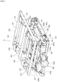
- FIG. 1 to FIG. 5 illustrate the entire configuration of a seat suspension mechanism 1 according to this embodiment.
- the seat suspension mechanism 1 supports a seat for vehicle of a passenger car, a truck, a bus, a forklift, or the like.
- the seat suspension mechanism 1 has a base frame 100 and a seat support frame 200, the base frame 100 is fixed to a vehicle floor on a vehicle body structure side, and the seat support frame 200 is attached on a seat side. Moreover, the seat suspension mechanism 1 includes an intermediate frame 300 between the base frame 100 and the seat support frame 200.
- the base frame 100 fixed to the vehicle floor is formed in a substantially square shape in plan view, and the intermediate frame 300 is supported through a first link mechanism 130.
- the first link mechanism 130 has a pair of left and right front links 131, 131 and a pair of left and right rear links 132, 132.
- front links 131, 131, lower portions 131a, 131a are rotatably supported close to the front portion of side edge portions 100a, 100a of the base frame 100, and upper portions 131b, 131b are linked close to a front frame 301 on side frames 303, 303 of the intermediate frame 300 (refer to FIG. 3 ).
- the intermediate frame 300 is movable up and down relative to the base frame 100, more accurately, since the first link mechanism 130 is constituted by a parallel link structure including the front links 131, 131 and the rear links 132, 132, the intermediate frame 300 moves up and down along a rotation trajectory of the front links 131, 131 and the rear links 132, 132.
- the intermediate frame 300 moves up and down.
- a first torsion bar 141a is disposed, and between connection center points of the side frames 303, 303 and the rear links 132, 132, a second torsion bar 141b is disposed (refer to FIG. 3 ).
- the first and second torsion bars 141a, 141b are linear springs which exhibit a linear characteristic that their load-deflection characteristic changes approximately linearly, and are combined with a later-described magnetic spring 142 to have a characteristic of being a constant load in a predetermined displacement range, thereby constituting a first spring mechanism 140 which elastically biases the intermediate frame 300.
- One-side ends of the first and second torsion bars 141a, 141b are linked to the upper portions 131b, 131b, 132b, 132b of the front links 131, 131 and the rear links 132, 132, and the other ends of the first and second torsion bars 141a, 141b are provided not to rotate relative to the side frames 303, 303 of the intermediate frame 300 respectively.
- the first and second torsion bars 141a, 141b are set to exhibit elastic force for biasing in a direction of relatively separating the intermediate frame 300 from the base frame 100, that is, in an upward direction. Further, the other ends of the first and second torsion bars 141a, 141b are connected to plate members 125c, 125d of an elastic force adjusting member 125 respectively (refer to FIG. 5 ).
- the elastic force adjusting member 125 is configured such that the rotation of its adjustment dial 125b causes the rotation of its adjustment shaft 125a, and this rotation causes the rotation of the plate member 125c connected to the first torsion bar 141a on the front links 131, 131 sides and then causes the rotation of the plate member 125d linked to the plate member 125c through a link plate 125e and connected to the second torsion bar 141b on the rear links 132, 132 sides.
- the adjustment dial 125b when the adjustment dial 125b is operated to rotate, the first and second torsion bars 141a, 141b are twisted in either direction, so that initial elastic force of the first and second torsion bars 141a, 141b is adjusted, and depending on the weight of a seated person, it is possible to adjust the position of the intermediate frame 300 and the later-described seat support frame 200 supported through the intermediate frame 300 to a predetermined position in the up-down direction (preferably a neutral position).
- the magnetic spring 142 includes a stationary magnet unit 1420 and a movable magnet unit 1421 as illustrated in FIG. 5 .
- the stationary magnet unit 1420 is fixed to the base frame 100, and has a pair of stationary magnets 1420a, 1420a arranged to face each other at a predetermined distance in a width direction of the base frame 100.
- the facing stationary magnets 1420a, 1420a are arranged so that bipolar magnets whose different poles are adjacent to each other in a vertical direction are used and the same poles face each other, for example.
- the movable magnet unit 1421 includes a movable magnet 1421a disposed in a space between the stationary magnets 1420a, 1420a disposed to face each other at the predetermined distance.
- the movable magnet 1421a is magnetized in the vertical direction, and supported by a support member 1422, and the support member 1422 is linked to the intermediate frame 300, for example. For this reason, when the intermediate frame 300 moves up and down relative to the base frame 100, the movable magnet 1421a supported by the support member 1422 is displaced up and down in the space between the stationary magnets 1420a, 1420a.
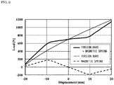
- the spring characteristic that the magnetic spring 142 exhibits when the movable magnet 1421a moves in the space between the stationary magnets 1420a, 1420a changes depending on a relative position of the movable magnet 1421a and the stationary magnets 1420a, 1420a. For example, as illustrated in FIG.
- the magnetic spring 142 exhibits, in its load-deflection characteristic, a negative spring characteristic that the restoring force in this direction reduces in a predetermined displacement amount range (a characteristic indicated with a dotted line in the chart).
- the negative spring characteristic is exhibited in a predetermined range in the vicinity of a position where the movable magnet 1421a crosses a boundary of the N pole and the S pole of the two stationary magnets 1420a, 1420a whose different poles are adjacent to each other (a range from about -9 mm to about +10 mm in an example in FIG. 6 ).
- the first spring mechanism 140 of this embodiment including the magnetic spring 142 and the above-described first and second torsion bars 141a, 141b, in the range where the negative spring characteristic acts in the magnetic spring 142 (the range from about -9 mm to about +10 mm in the example in FIG. 6 ), a spring constant is reduced.
- the reduction in the spring constant resulting from the superposition of the positive spring characteristic of the first and second torsion bars 141a, 141b and the negative spring characteristic of the magnetic spring 142 is as described above, and as the spring characteristic obtained by superposing the two, a configuration to have a constant load region where a change amount of a load value is equal to or less than a predetermined amount even if the displacement amount increases, that is, a region where the spring constant is substantially zero (preferably, a spring constant within a range of about -10 N/mm to about 10 N/mm) is preferred.
- the seat support frame 200 is formed in a substantially square shape having a front frame 201, a rear frame 202, and side frames 203, 203 each connecting end portions of the front frame 201 and the rear frame 202 with each other (refer to FIG. 1 and FIG. 2 ).
- the seat support frame 200 is supported with respect to the intermediate frame 300 through a second link mechanism 230.
- the second link mechanism 230 is constituted by a parallel link structure having a pair of left and right front links 231, 231 and a pair of left and right rear links 232, 232, similarly to the above-described first link mechanism 130, as illustrated in FIG. 3 .
- Lower portions 231a, 231a of the front links 231, 231 are supported by first brackets 304a, 304a fixed close to a front portion of the side frames 303, 303 of the intermediate frame 300.
- Lower portions 232a, 232a of the rear links 232, 232 are supported by second brackets 305a, 305a fixed close to a rear portion of the side frames 303, 303 of the intermediate frame 300.
- Upper portions 231b, 231b of the front links 231, 231 are supported by an attachment shaft 204 suspended between the side frames 203, 203 close to the front frame 201 of the seat support frame 200, and upper portions 232b, 232b of the rear links 232, 232 are supported by an attachment shaft 205 suspended between the side frames 203, 203 close to the rear frame 202 thereof.
- the seat support frame 200 rotatably moves with respect to the intermediate frame 300 centered at the lower portions 231a, 232a of the front links 231, 231 and the rear links 232, 232.
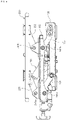
- the links 131, 131, 132, 132 of the first link mechanism 130 are designed to, in a forward inclined position at a balanced point, change the movement of the intermediate frame 300 within this forward inclined position
- the links 231, 231, 232, 232 of the second link mechanism 230 are designed to be in a backward inclined position at the balanced point and to change the movement of the seat support frame 200 within this backward inclined position.
- the links 131, 131, 132, 132 of the first link mechanism 130 and the links 231, 231, 232, 232 of the second link mechanism 230 are attached so that with respect to the change in up-down movement, rotation directions are opposite. This allows a reduction in front-rear movement of the seat support frame 200 and a seat supported by it.
- a third torsion bar 241a is disposed, and between connection center points of the lower portions 232a, 232a of the rear links 232, 232 of the second link mechanism 230 supported by the second brackets 305a, 305a, a fourth torsion bar 241b is disposed (refer to FIG. 3 ).
- a second spring mechanism 240 is constituted of the third and fourth torsion bars 241a, 241b.
- One-side ends of the third and fourth torsion bars 241a, 241b are linked to the lower portions 231a, 231b, 232a, 232b of the front links 231, 231 and the rear links 232, 232, and the other ends of the third and fourth torsion bars 241a, 241b are provided not to rotate relative to the first and second brackets 304a, 304a, 305a, 305a of the intermediate frame 300 respectively. This causes the one-side ends and the other ends in a long direction of the third and fourth torsion bars 241a, 241b to be relatively twisted.
- the first spring mechanism 140 has the characteristic of forming the constant load region where the spring constant is substantially zero, and the seat suspension mechanism 1 further has the second spring mechanism 240 constituted of the third and fourth torsion bars 241a, 241b in this embodiment.
- This allows the overall spring characteristic of the seat suspension mechanism 1 obtained by adding up the first spring mechanism 140 and the second spring mechanism 240 to be set variously by adjusting a twist amount when the third and fourth torsion bars 241a, 241b are initialized.
- FIG. 7 to FIG. 9 illustrate examples of setting of the third and fourth torsion bars 241a, 241b.
- the charts each illustrate the load-deflection characteristic of the first spring mechanism 140 combining the first and second torsion bars 141a, 141b and the magnetic spring 142, a load-deflection characteristic of the second spring mechanism 240 of the third and fourth torsion bars 241a, 241b, and a load-deflection characteristic of the entire seat suspension mechanism 1 combining the first spring mechanism 140 and the second spring mechanism 240.
- FIG. 7 illustrates an example in which the second spring mechanism 240 is set to exhibit a linear positive spring constant when the seat support frame 200 and the intermediate frame 300 are displaced downward over the balanced point (the position of 0 mm) from an upper position.
- FIG. 8 illustrates an example in which the third and fourth torsion bars 241a, 241b of the second spring mechanism 240 are set to be released from twisting at the position of "-10 mm" short of the balanced point, and twisted again when the seat support frame 200 and the intermediate frame 300 are displaced downward from the position, and FIG.
- the second spring mechanism 240 has a characteristic of exhibiting a nonlinear characteristic at the point where a biasing direction changes in the middle of the change, and exhibiting a negative spring characteristic that the seat support frame 200 and the intermediate frame 300 are biased downward to the predetermined position (in FIG. 8 , to the position of "-10 mm" short of the balanced point, in FIG. 9 , to the position of the balanced point) when they are displaced downward from the upper position.
- the second spring mechanism 240 acts as braking force, and can also impart a characteristic of preventing topping through setting of the third and fourth torsion bars 241a, 241b. Accordingly, the setting of the above-described third and fourth torsion bars 241a, 241b of the second spring mechanism 240 allows a damping ratio corresponding to a rise in acceleration to be designed.
- the seat suspension mechanism 1 of this embodiment has the second spring mechanism 240 including the third and fourth torsion bars 241a, 241b, and thereby, adjusting them allows a configuration including various characteristics.
- a damper 150 which exhibits damping force to absorb energy when the two move up and down relatively is provided.
- the damper 150 is suspended with the intermediate frame 300 located between the base frame 100 and the seat support frame 200 skipped.
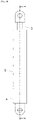
- the damper 150 is a telescopic one including a cylinder 151 and a piston 152 which moves relatively in the cylinder 151 as illustrated in FIG. 10 and FIG. 11 .
- a normal oil damper or the like can also be used as the damper 150, and a movement zone of the piston 152 in the cylinder 151 corresponding to a predetermined up-down movement range including the balanced point when a person is seated (the position when seated in a static state.
- the position aligned with the neutral position of the intermediate frame 300 as much as possible by an adjustment with the elastic force adjusting member 125) is preferably a free running zone where the damping force does not act.
- the damper 150 having such a free running zone takes on a dual cylinder structure in which the cylinder 151 includes an outer fixed cylinder 1511 and an inner movable cylinder 1512 disposed in the inside thereof as illustrated in FIG. 11 .
- the piston 152 is disposed to be slidable in the inner movable cylinder 1512. Stopper portions 1511a, 1511b are provided at long-side-direction end portions of the outer fixed cylinder 1511, and the inner movable cylinder 1512 is shorter in axial-direction length than the outer fixed cylinder 1511 and can move until end portions 1512a, 1512b in the long-side direction of the inner movable cylinder 1512 abut on the stopper portions 1511a, 1511b.
- the piston 152 is also similar, and can move until end portions 152a, 152b in the long-side direction abut on the stopper portions 1511a, 1511b.
- the inner movable cylinder 1512 is longer than the piston 152, and the piston rod 153 is linked to the piston 152.
- the piston 152 is provided with a string portion 152c formed by winding a linear member such as a thread which exhibits a predetermined friction damping force between the inner movable cylinder 1512 and the piston 152 around its outer peripheral portion.
- a viscous fluid such as grease having low consistency is made to adhere to the string portion 152c.
- the viscous fluid can be made to adhere to the linear member such as the thread composing the string portion 152c by impregnation or coating. Accordingly, when the piston 152 moves relative to the inner movable cylinder 1512, the friction damping force caused by tension of the linear member composing the string portion 152c and viscous damping force of speed dependence caused by the viscous fluid act.
- a low-friction member 1513 such as a rolling member or a sliding member (for example, felt) is interposed.
- a range where the inner movable cylinder 1512 of the cylinder 151 moves relatively in the outer fixed cylinder 1511 becomes a free running zone where the damping force does not substantially act, and a distance of the free running zone corresponds to a difference in the axial-direction length between the outer fixed cylinder 1511 and the inner movable cylinder 1512.
- the inner movable cylinder 1512 is set to be at a substantially middle position of the entire movement range in the outer fixed cylinder 1511. This causes the predetermined up-down movement range including the balanced point to be formed evenly on the upper and lower sides thereof centered at the balance point.
- the damping force does not substantially act, and the first spring mechanism 140 and the second spring mechanism 240 mainly serve a vibration absorbing function, and in a case where a vibration with a low-frequency amplitude equal to or larger than a predetermined amplitude is input, the damping force of the damper 150 acts to absorb impact energy.
- the damper 150 skips over the intermediate frame 300 and is suspended between the base frame 100 and the seat support frame 200. Accordingly, phases with respect to vibrations differ between the seat support frame 200 on which the damping force of the damper 150 acts directly and the intermediate frame 300 on which the characteristic of the damper 150 does not act directly. As a result, it is possible to exhibit high vibration absorption characteristic and impact absorption characteristic.
- the characteristic of the seat suspension mechanism 1 can be varied depending on the directions of disposing the damper 150. That is, as illustrated in FIG. 3 , when the damper 150 is disposed to be inclined in a direction of crossing an inclined direction of the links 131, 132 of the first link mechanism 130 at the balanced point, the damper 150 acts more efficiently with respect to movements of the first link mechanism 130 and the first spring mechanism 140 than when disposed in a direction as illustrated in FIG. 4 opposite to that in FIG. 3 . On the other hand, as illustrated in FIG.
- one end of the damper 150 is not attached to the intermediate frame 300, and is attached to the seat support frame 200.
- the damping force of the damper 150 disposed in the direction in FIG. 4 is more likely to act than the one disposed in such a direction as in FIG. 3 .
- the spring characteristic is strengthened in the state in FIG. 3
- a damping characteristic is strengthened in the state in FIG. 4 .
- two dampers 150A, 150B can be configured to be disposed in an X shape when seen from the side thereof, that is, can also be configured to use the damper 150A disposed in the inclined position crossing the inclined direction of the links 131, 132 of the first link mechanism 130 at the balanced point and the damper 150B disposed in the direction opposite thereto, that is, in the inclined position crossing the inclined direction of the links 231, 232 of the second link mechanism 230 at the balanced point in combination.
- a seated person adjusts the elastic force of the first spring mechanism 140 and sets the seat support frame 200 and the intermediate frame 300 to be at the neutral position (balanced point) in the up-down displacement range by using the first elastic force adjusting member 125.
- the links 131, 132 of the first link mechanism 130 move up and down while following the rotation trajectory centered at their lower portions 131a, 132a, and the links of the second link mechanism 230 also move up and down while following a rotation trajectory centered at their lower portions 231a, 232a.
- the first spring mechanism 140 in response to the movement of the first link mechanism 130 has the characteristic of including the constant load region
- the second spring mechanism 240 in response to the movement of the second link mechanism 230 has the linear or nonlinear characteristic as illustrated in FIG. 7 to FIG. 9 . This causes the phase shift to occur between the movement of the first link mechanism 130 and the movement of the second link mechanism 230, which efficiently absorbs the vibrations.
- the dampers 150, 150A, 150B are each suspended between the base frame 100 and the seat support frame 200, and thereby the phase shift is likely to occur between the movement of the first link mechanism 130 and the movement of the second link mechanism 230, which allows the efficient absorption of vibrations.
- various forms of the inclined directions when the dampers 150, 150A, 150B are disposed allow control of the phase and adjustment of setting of the vibration absorption characteristic and the impact absorption characteristic.
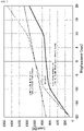
- FIG. 12 illustrates the result of the vibration test performed by attaching a seat on the seat suspension mechanism 1 of this embodiment and seating a male subject (a weight of 64 kg) thereon.
- the vibration test was performed by the excitation according to a standard for the input spectral class EM7 "compact dumper" defined in JIS A 8304:2001 "Earth moving machinery-Laboratory evaluation of operator seat vibration” based on ISO 7096:2000. Specifically, the excitation was performed under a 3.24 Hz dominant frequency and a 5.56 (m/s 2 ) 2 /Hz maximum value of PSD.
- a vibrator a 6-axis vibrator manufactured by DELTA TOOLING CO., LTD. was used, and on a vibration table of the vibrator, the seat suspension mechanism 1 in which a seat was attached on the seat support frame 200 was set, and the subject was seated on the seat.
- a reference sign A indicates the test result of the seat suspension mechanism 1 in which the damper 150 is disposed in the inclined direction illustrated in FIG. 3
- a reference sign B indicates the test result of the seat suspension mechanism 1 in which the damper 150 is disposed in the inclined direction illustrated in FIG. 4 .
- resonant frequencies in EM7 were 1.0 Hz in both cases.
- Gains at a resonance peak were each less than 2.0, but as compared with the state in FIG. 3 indicated by the reference sign A, in the state in FIG.
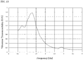
- FIG. 13 is a chart illustrating the result of a damping test in which a rubber weight with load mass of 75 kg was fixed and attached on the seat with a belt and a logarithmic swept sine wave (0.5 to 4.0 Hz) was excited by a ⁇ 16 mm input amplitude (a displacement amplitude corresponding to 40% of the total stroke amount of 80 mm of the seat suspension mechanism 1000).
- the damper 150 the one disposed in the state illustrated in FIG. 3 is used as the damper 150.
- a resonant frequency was 1.30 Hz
- a gain at a resonance peak was 1.77.
- the seat suspension mechanism 1 of this embodiment has a high vibration damping function.
Landscapes
- Engineering & Computer Science (AREA)
- Aviation & Aerospace Engineering (AREA)
- Transportation (AREA)
- Mechanical Engineering (AREA)
- Seats For Vehicles (AREA)
Abstract
Description
- The present invention relates to a seat suspension mechanism used for support for a seat of a vehicle.
-
Patent Documents - The seat suspension mechanism of
Patent Documents - However, in a case of a driver seat of an earth-moving machine, because there are many occasions to run on a road surface having large bumps and potholes, it is necessary to put emphasis on measures against impact vibrations having a larger amplitude.
- In consideration of this point,
Patent Document 3 proposes a seat suspension mechanism having a structure in which spring-damper attached suspension units are stacked in plurality. -
- Patent Document 1:
Japanese Patent Application Laid-open 2010-179719 - Patent Document 2:
Japanese Patent Application Laid-open 2010-179720 - Patent Document 3:
Japanese Patent Application Laid-open 2019-48489 - However, the seat suspension mechanism in
Patent Document 3 includes a spring mechanism and a damper mechanism for each tier, which complicates the structure. - The present invention was made in consideration of the above point, and has an object to provide a seat suspension mechanism capable of exhibiting high vibration absorption characteristic and impact absorption characteristic with a simpler configuration.
- To solve the above problem, a seat suspension mechanism of the present invention disposed between a vehicle body structure and a seat, the seat suspension mechanism includes:
- a base frame attached on the vehicle body structure side;
- a seat support frame attached on the seat side;
- an intermediate frame located between the base frame and the seat support frame;
- a first link mechanism supporting the intermediate frame with respect to the base frame;
- a second link mechanism supporting the seat support frame with respect to the intermediate frame;
- a first spring mechanism which elastically biases the intermediate frame;
- a second spring mechanism which elastically biases the seat support frame; and a damper suspended between the base frame and the seat support frame.
- The first link mechanism and the second link mechanism are each constituted by a parallel link structure, and meanwhile, are attached so that a rotation direction of links of the first link mechanism and a rotation direction of links of the second link mechanism, in accordance with a displacement of the intermediate frame or the seat support frame, are opposite, and
wherein the damper is attached in a position in an inclined direction opposite to an inclined direction of the links of the first link mechanism at a balanced point. - The first link mechanism and the second link mechanism are each constituted by a parallel link structure, and meanwhile, are attached so that a rotation direction of links of the first link mechanism and a rotation direction of links of the second link mechanism, in accordance with a displacement of the intermediate frame or the seat support frame, are opposite, and
wherein the damper is attached in a position in an inclined direction opposite to an inclined direction of the links of the second link mechanism at a balanced point. - The first link mechanism and the second link mechanism are each constituted by a parallel link structure, and meanwhile, are attached so that a rotation direction of links of the first link mechanism and a rotation direction of links of the second link mechanism, in accordance with a displacement of the intermediate frame or the seat support frame, are opposite, and
wherein two kinds of the dampers whose inclined directions are opposite to each other are disposed. - Preferably, as the first spring mechanism and the second spring mechanism, torsion bars linked to any link of the first link mechanism and any link of the second link mechanism to be rotated are respectively used, and an initial position at a twist angle of each of the torsion bars is adjustable.
- Preferably, when the torsion bar linked to any link of the second link mechanism is displaced downward from an upper position, the initial position is set to exhibit a negative spring characteristic of downward biasing to a predetermined position.
- Preferably, the first spring mechanism includes:
- a linear spring which exhibits a linear characteristic of biasing in a direction of separating the intermediate frame from the base frame in a normal state; and
- a magnetic spring which includes stationary magnets and a movable magnet whose relative position to the stationary magnets is displaced in accordance with up-down movement of the intermediate frame relative to the base frame, and exhibits a nonlinear spring characteristic that a spring constant is changed depending on the relative position of the stationary magnets and the movable magnet, and
- wherein a spring characteristic of combining the linear spring and the magnetic spring includes a characteristic of being a constant load when the intermediate frame is located in a predetermined up-down movement range including a balanced point.
- Preferably, the first spring mechanism further includes
- an auxiliary spring mechanism which includes, between the base frame and the intermediate frame, a pantograph link in which connection points of upper-side links and lower-side links are displaced in a front-rear direction and a tensile coil spring suspended on the pantograph link in the front-rear direction, and exhibits a spring characteristic of biasing the intermediate frame downward when the intermediate frame is located in the predetermined up-down movement range including the balanced point, and
- wherein a spring characteristic of further combining the auxiliary spring mechanism with the linear spring and the magnetic spring includes the characteristic of being the constant load when the intermediate frame is located in the predetermined up-down movement range including the balanced point.
- In the seat suspension mechanism of the present invention, the intermediate frame is supported through the first link mechanism by the base frame and the seat support frame is supported through the second link mechanism by the intermediate frame, and the first spring mechanism which elastically biases the intermediate frame and the second spring mechanism which elastically biases the seat support frame are included, and meanwhile, the damper is suspended between the base frame and the seat support frame excluding the intermediate frame. Accordingly, despite a simple configuration as compared with the conventional seat suspension mechanism having the multitiered structure, phases with respect to vibrations differ between the seat support frame on which damping force of the damper acts directly and the intermediate frame on which a characteristic of the damper does not act directly, which makes it possible to exhibit high vibration absorption characteristic and impact absorption characteristic.
-
- [
FIG. 1] FIG. 1 is a perspective view illustrating a seat suspension mechanism according to one embodiment of the present invention. - [
FIG. 2] FIG. 2 is a plan view ofFIG. 1 . - [
FIG. 3] FIG. 3 is a side view ofFIG. 1 . - [
FIG. 4] FIG. 4 is a side view illustrating a state of setting an inclined direction when a damper is attached to be in a direction opposite to that inFIG. 3 . - [
FIG. 5] FIG. 5 is a side view illustrating a state of disposing two dampers in an X shape. - [
FIG. 6] FIG. 6 is a chart for explaining a characteristic of linear springs and a negative spring characteristic of a magnetic spring, and, a characteristic in a constant load region obtained by combining them, of a first spring mechanism. - [
FIG. 7] FIG. 7 is a chart illustrating one example of the spring characteristic of the first spring mechanism, a spring characteristic of a second spring mechanism, and a spring characteristic obtained by combining them. - [
FIG. 8] FIG. 8 is a chart illustrating another example of the spring characteristic of the first spring mechanism, a spring characteristic of the second spring mechanism, and a spring characteristic obtained by combining them. - [
FIG. 9] FIG. 9 is a chart further illustrating the other example of the spring characteristic of the first spring mechanism, a spring characteristic of the second spring mechanism, and a spring characteristic obtained by combining them. - [
FIG. 10] FIG. 10 is a side view of a damper. - [
FIG. 11] FIG. 11 is a sectional view taken along a B-B line ofFIG. 10 . - [
FIG. 12] FIG. 12 is a chart illustrating a vibration transmissibility in an EM7 related vibration test performed on the seat suspension mechanism of the above embodiment. - [
FIG. 13] FIG. 13 is a chart illustrating a vibration transmissibility in a damping test performed on the seat suspension mechanism of the above embodiment. - The present invention will be hereinafter described in more detail based on embodiments illustrated in the drawings.
FIG. 1 to FIG. 5 illustrate the entire configuration of aseat suspension mechanism 1 according to this embodiment. Theseat suspension mechanism 1 supports a seat for vehicle of a passenger car, a truck, a bus, a forklift, or the like. - As illustrated in
FIG. 1 , theseat suspension mechanism 1 has abase frame 100 and aseat support frame 200, thebase frame 100 is fixed to a vehicle floor on a vehicle body structure side, and theseat support frame 200 is attached on a seat side. Moreover, theseat suspension mechanism 1 includes anintermediate frame 300 between thebase frame 100 and theseat support frame 200. Thebase frame 100 fixed to the vehicle floor is formed in a substantially square shape in plan view, and theintermediate frame 300 is supported through afirst link mechanism 130. - The
first link mechanism 130 has a pair of left and rightfront links rear links front links lower portions side edge portions base frame 100, andupper portions front frame 301 on side frames 303, 303 of the intermediate frame 300 (refer toFIG. 3 ). - In the
rear links lower portions side edge portions base frame 100, andupper portions intermediate frame 300. With this structure, theintermediate frame 300 is movable up and down relative to thebase frame 100, more accurately, since thefirst link mechanism 130 is constituted by a parallel link structure including thefront links rear links intermediate frame 300 moves up and down along a rotation trajectory of thefront links rear links front links rear links lower portions links base frame 100, as rotation centers, that is, along a direction in which thefront links rear links FIG. 3 ) and a direction in which they return to the opposite of the above direction to go toward an upper limit position (a clockwise direction inFIG. 4 ), theintermediate frame 300 moves up and down. - Between connection center points of the side frames 303, 303 separated at a predetermined distance in a width direction in the
intermediate frame 300 and thefront links first torsion bar 141a is disposed, and between connection center points of the side frames 303, 303 and therear links second torsion bar 141b is disposed (refer toFIG. 3 ). In this embodiment, the first andsecond torsion bars magnetic spring 142 to have a characteristic of being a constant load in a predetermined displacement range, thereby constituting afirst spring mechanism 140 which elastically biases theintermediate frame 300. One-side ends of the first andsecond torsion bars upper portions front links rear links second torsion bars intermediate frame 300 respectively. - Hence, the first and
second torsion bars intermediate frame 300 from thebase frame 100, that is, in an upward direction. Further, the other ends of the first andsecond torsion bars force adjusting member 125 respectively (refer toFIG. 5 ). - The elastic
force adjusting member 125 is configured such that the rotation of itsadjustment dial 125b causes the rotation of itsadjustment shaft 125a, and this rotation causes the rotation of the plate member 125c connected to thefirst torsion bar 141a on thefront links second torsion bar 141b on therear links adjustment dial 125b is operated to rotate, the first andsecond torsion bars second torsion bars intermediate frame 300 and the later-describedseat support frame 200 supported through theintermediate frame 300 to a predetermined position in the up-down direction (preferably a neutral position). - The
magnetic spring 142 includes astationary magnet unit 1420 and amovable magnet unit 1421 as illustrated inFIG. 5 . Thestationary magnet unit 1420 is fixed to thebase frame 100, and has a pair ofstationary magnets base frame 100. The facingstationary magnets movable magnet unit 1421 includes amovable magnet 1421a disposed in a space between thestationary magnets movable magnet 1421a is magnetized in the vertical direction, and supported by asupport member 1422, and thesupport member 1422 is linked to theintermediate frame 300, for example. For this reason, when theintermediate frame 300 moves up and down relative to thebase frame 100, themovable magnet 1421a supported by thesupport member 1422 is displaced up and down in the space between thestationary magnets - The spring characteristic that the
magnetic spring 142 exhibits when themovable magnet 1421a moves in the space between thestationary magnets movable magnet 1421a and thestationary magnets FIG. 6 , if a characteristic that restoring force increases in a working direction of the elastic force (restoring force) of the first andsecond torsion bars intermediate frame 300 from thebase frame 100 is referred to as a positive spring characteristic, themagnetic spring 142 exhibits, in its load-deflection characteristic, a negative spring characteristic that the restoring force in this direction reduces in a predetermined displacement amount range (a characteristic indicated with a dotted line in the chart). That is, the negative spring characteristic is exhibited in a predetermined range in the vicinity of a position where themovable magnet 1421a crosses a boundary of the N pole and the S pole of the twostationary magnets FIG. 6 ). - As a result, in the
first spring mechanism 140 of this embodiment including themagnetic spring 142 and the above-described first andsecond torsion bars FIG. 6 ), a spring constant is reduced. - Here, the reduction in the spring constant resulting from the superposition of the positive spring characteristic of the first and
second torsion bars magnetic spring 142 is as described above, and as the spring characteristic obtained by superposing the two, a configuration to have a constant load region where a change amount of a load value is equal to or less than a predetermined amount even if the displacement amount increases, that is, a region where the spring constant is substantially zero (preferably, a spring constant within a range of about -10 N/mm to about 10 N/mm) is preferred. - The
seat support frame 200 is formed in a substantially square shape having afront frame 201, arear frame 202, and side frames 203, 203 each connecting end portions of thefront frame 201 and therear frame 202 with each other (refer toFIG. 1 andFIG. 2 ). Theseat support frame 200 is supported with respect to theintermediate frame 300 through asecond link mechanism 230. Thesecond link mechanism 230 is constituted by a parallel link structure having a pair of left and rightfront links rear links first link mechanism 130, as illustrated inFIG. 3 .Lower portions front links first brackets intermediate frame 300.Lower portions rear links second brackets intermediate frame 300. -
Upper portions front links attachment shaft 204 suspended between the side frames 203, 203 close to thefront frame 201 of theseat support frame 200, andupper portions rear links attachment shaft 205 suspended between the side frames 203, 203 close to therear frame 202 thereof. - The
seat support frame 200 rotatably moves with respect to theintermediate frame 300 centered at thelower portions front links rear links links first link mechanism 130 are designed to, in a forward inclined position at a balanced point, change the movement of theintermediate frame 300 within this forward inclined position, whereas thelinks second link mechanism 230 are designed to be in a backward inclined position at the balanced point and to change the movement of theseat support frame 200 within this backward inclined position. That is, thelinks first link mechanism 130 and thelinks second link mechanism 230 are attached so that with respect to the change in up-down movement, rotation directions are opposite. This allows a reduction in front-rear movement of theseat support frame 200 and a seat supported by it. - Between connection center points of the
lower portions front links second link mechanism 230 supported by thefirst brackets intermediate frame 300, athird torsion bar 241a is disposed, and between connection center points of thelower portions rear links second link mechanism 230 supported by thesecond brackets fourth torsion bar 241b is disposed (refer toFIG. 3 ). In this embodiment, asecond spring mechanism 240 is constituted of the third andfourth torsion bars fourth torsion bars lower portions front links rear links fourth torsion bars second brackets intermediate frame 300 respectively. This causes the one-side ends and the other ends in a long direction of the third andfourth torsion bars - As described above, owing to a combination of the first and
second torsion bars magnetic spring 142, thefirst spring mechanism 140 has the characteristic of forming the constant load region where the spring constant is substantially zero, and theseat suspension mechanism 1 further has thesecond spring mechanism 240 constituted of the third andfourth torsion bars seat suspension mechanism 1 obtained by adding up thefirst spring mechanism 140 and thesecond spring mechanism 240 to be set variously by adjusting a twist amount when the third andfourth torsion bars -
FIG. 7 to FIG. 9 illustrate examples of setting of the third andfourth torsion bars first spring mechanism 140 combining the first andsecond torsion bars magnetic spring 142, a load-deflection characteristic of thesecond spring mechanism 240 of the third andfourth torsion bars seat suspension mechanism 1 combining thefirst spring mechanism 140 and thesecond spring mechanism 240. -
FIG. 7 illustrates an example in which thesecond spring mechanism 240 is set to exhibit a linear positive spring constant when theseat support frame 200 and theintermediate frame 300 are displaced downward over the balanced point (the position of 0 mm) from an upper position.FIG. 8 illustrates an example in which the third andfourth torsion bars second spring mechanism 240 are set to be released from twisting at the position of "-10 mm" short of the balanced point, and twisted again when theseat support frame 200 and theintermediate frame 300 are displaced downward from the position, andFIG. 9 illustrates an example in which the third andfourth torsion bars second spring mechanism 240 are set to be released from twisting at the balanced point, and twisted again when theseat support frame 200 and theintermediate frame 300 are displaced downward from the point. That is, in each ofFIG. 8 andFIG. 9 , thesecond spring mechanism 240 has a characteristic of exhibiting a nonlinear characteristic at the point where a biasing direction changes in the middle of the change, and exhibiting a negative spring characteristic that theseat support frame 200 and theintermediate frame 300 are biased downward to the predetermined position (inFIG. 8 , to the position of "-10 mm" short of the balanced point, inFIG. 9 , to the position of the balanced point) when they are displaced downward from the upper position. This results in that when theseat support frame 200 and theintermediate frame 300 rise over this predetermined position (inFIG. 8 , the position of "-10 mm" short of the balanced point, inFIG. 9 , the position of the balanced point) when displaced upward from a lower position, thesecond spring mechanism 240 acts as braking force, and can also impart a characteristic of preventing topping through setting of the third andfourth torsion bars fourth torsion bars second spring mechanism 240 allows a damping ratio corresponding to a rise in acceleration to be designed. - In comparison of the load-deflection characteristic of the entire
seat suspension mechanism 1, on the basis of the characteristic inFIG. 7 , in the case inFIG. 8 , a spring constant up to "-10 mm" is reduced, and in the case inFIG. 9 , a spring constant in a range "from -10 mm to 0 mm" can be particularly reduced. Hence, theseat suspension mechanism 1 of this embodiment has thesecond spring mechanism 240 including the third andfourth torsion bars - Here, between the
base frame 100 and theseat support frame 200, adamper 150 which exhibits damping force to absorb energy when the two move up and down relatively is provided. In this embodiment, without suspending the damper between theintermediate frame 300 and thebase frame 100 and between theintermediate frame 300 and theseat support frame 200, thedamper 150 is suspended with theintermediate frame 300 located between thebase frame 100 and theseat support frame 200 skipped. - The
damper 150 is a telescopic one including acylinder 151 and apiston 152 which moves relatively in thecylinder 151 as illustrated inFIG. 10 andFIG. 11 . A normal oil damper or the like can also be used as thedamper 150, and a movement zone of thepiston 152 in thecylinder 151 corresponding to a predetermined up-down movement range including the balanced point when a person is seated (the position when seated in a static state. The position aligned with the neutral position of theintermediate frame 300 as much as possible by an adjustment with the elastic force adjusting member 125) is preferably a free running zone where the damping force does not act. - The
damper 150 having such a free running zone takes on a dual cylinder structure in which thecylinder 151 includes an outerfixed cylinder 1511 and an innermovable cylinder 1512 disposed in the inside thereof as illustrated inFIG. 11 . Thepiston 152 is disposed to be slidable in the innermovable cylinder 1512.Stopper portions fixed cylinder 1511, and the innermovable cylinder 1512 is shorter in axial-direction length than the outerfixed cylinder 1511 and can move untilend portions movable cylinder 1512 abut on thestopper portions piston 152 is also similar, and can move untilend portions stopper portions movable cylinder 1512 is longer than thepiston 152, and thepiston rod 153 is linked to thepiston 152. - The
piston 152 is provided with astring portion 152c formed by winding a linear member such as a thread which exhibits a predetermined friction damping force between the innermovable cylinder 1512 and thepiston 152 around its outer peripheral portion. In this embodiment, a viscous fluid such as grease having low consistency is made to adhere to thestring portion 152c. The viscous fluid can be made to adhere to the linear member such as the thread composing thestring portion 152c by impregnation or coating. Accordingly, when thepiston 152 moves relative to the innermovable cylinder 1512, the friction damping force caused by tension of the linear member composing thestring portion 152c and viscous damping force of speed dependence caused by the viscous fluid act. That is, by a relative displacement of thepiston 152 to the innermovable cylinder 1512, friction force between the two is converted to the tension of thestring portion 152c, and with an increase in the displacement amount, the thread composing thestring portion 152c is hardened integrally to change in the course of reducing a friction coefficient, thereby suppressing heat generation. This change causes the viscous damping force to be speed-dependent. Therefore, the action of the friction damping force becomes relatively large in a low-speed input, but the viscous damping force becomes higher as the speed increases. Note that depending on increase and decrease in the number of turns of the thread composing thestring portion 152c, a gap between adjacent portions of the wound thread, the number of stacks of the wound thread, or the like, the friction force and the viscous damping force to be generated are appropriately controlled. - On one hand, between an outer peripheral surface of the inner
movable cylinder 1512 and an inner peripheral surface of the outerfixed cylinder 1511, so as to make friction force between the two relatively smaller than the friction force generated by thestring portion 152c between the innermovable cylinder 1512 and thepiston 152, in this embodiment, between the innermovable cylinder 1512 and the outerfixed cylinder 1511, a low-friction member 1513 such as a rolling member or a sliding member (for example, felt) is interposed. - This makes the inner
movable cylinder 1512 and thepiston 152 move together in the outerfixed cylinder 1511 owing to a difference between the friction force between the innermovable cylinder 1512 and thepiston 152, and, the friction force between the innermovable cylinder 1512 and the outerfixed cylinder 1511 until theend portions 1512a 1512b of the innermovable cylinder 1512 abut on thestopper portions 1511a 1511b when thepiston 152 moves relatively in thecylinder 151 while following movement of thepiston rod 153. At this time, frictional resistance is very small between the innermovable cylinder 1512 and the outerfixed cylinder 1511 owing to the low-friction member 1513, and the innermovable cylinder 1512 substantially freely runs in the outerfixed cylinder 1511 to generate little damping force. After theend portions movable cylinder 1512 abut on either of thestopper portions movable cylinder 1512 is prevented from moving, thepiston 152 slides in the innermovable cylinder 1512 alone. This causes such friction damping force and viscous damping force as described above to act between thepiston 152 and the innermovable cylinder 1512. - Accordingly, a range where the inner
movable cylinder 1512 of thecylinder 151 moves relatively in the outerfixed cylinder 1511 becomes a free running zone where the damping force does not substantially act, and a distance of the free running zone corresponds to a difference in the axial-direction length between the outerfixed cylinder 1511 and the innermovable cylinder 1512. As a result, when theintermediate frame 300 is located in the predetermined up-down movement range including the balanced point, the movement zone where thepiston 152 does not move relative to the innermovable cylinder 1512 and the damping force does not effectively work is formed. Preferably, at the balanced point in a seated state when theintermediate frame 300 moves up and down relative to the base frame 100 (the position adjusted so as to be aligned with the neutral position of the entire stroke, in which theintermediate frame 300 can move up and down, as much as possible), the innermovable cylinder 1512 is set to be at a substantially middle position of the entire movement range in the outerfixed cylinder 1511. This causes the predetermined up-down movement range including the balanced point to be formed evenly on the upper and lower sides thereof centered at the balance point. - When the
seat support frame 200 and theintermediate frame 300 are swung relatively by a vibration input during driving, in a case where thedamper 150 responds to the aforesaid free running zone, the damping force does not substantially act, and thefirst spring mechanism 140 and thesecond spring mechanism 240 mainly serve a vibration absorbing function, and in a case where a vibration with a low-frequency amplitude equal to or larger than a predetermined amplitude is input, the damping force of thedamper 150 acts to absorb impact energy. - However, in this embodiment, as described above, the
damper 150 skips over theintermediate frame 300 and is suspended between thebase frame 100 and theseat support frame 200. Accordingly, phases with respect to vibrations differ between theseat support frame 200 on which the damping force of thedamper 150 acts directly and theintermediate frame 300 on which the characteristic of thedamper 150 does not act directly. As a result, it is possible to exhibit high vibration absorption characteristic and impact absorption characteristic. - Further, depending on the directions of disposing the
damper 150, the characteristic of theseat suspension mechanism 1 can be varied. That is, as illustrated inFIG. 3 , when thedamper 150 is disposed to be inclined in a direction of crossing an inclined direction of thelinks first link mechanism 130 at the balanced point, thedamper 150 acts more efficiently with respect to movements of thefirst link mechanism 130 and thefirst spring mechanism 140 than when disposed in a direction as illustrated inFIG. 4 opposite to that inFIG. 3 . On the other hand, as illustrated inFIG. 4 , when thedamper 150 is disposed in a position inclined in a direction of crossing an inclined direction of thelinks second link mechanism 230 at the balanced point, thedamper 150 acts more efficiently with respect to movements of thesecond link mechanism 230 and thesecond spring mechanism 240 than the case inFIG. 3 . - Meanwhile, in this embodiment, one end of the
damper 150 is not attached to theintermediate frame 300, and is attached to theseat support frame 200. Hence, the damping force of thedamper 150 disposed in the direction inFIG. 4 is more likely to act than the one disposed in such a direction as inFIG. 3 . Accordingly, as the entireseat suspension mechanism 1, the spring characteristic is strengthened in the state inFIG. 3 , and a damping characteristic is strengthened in the state inFIG. 4 . - On one hand, as illustrated in
FIG. 5 , twodampers damper 150A disposed in the inclined position crossing the inclined direction of thelinks first link mechanism 130 at the balanced point and thedamper 150B disposed in the direction opposite thereto, that is, in the inclined position crossing the inclined direction of thelinks second link mechanism 230 at the balanced point in combination. In this case, a higher damping force can be made to act, but a difference in timings at which damping forces of the twodampers first link mechanism 130 and movement of thesecond link mechanism 230 to occur, which allows a high vibration absorption characteristic to be exhibited similarly to the states inFIG. 3 andFIG. 4 . - According to this embodiment, a seated person adjusts the elastic force of the
first spring mechanism 140 and sets theseat support frame 200 and theintermediate frame 300 to be at the neutral position (balanced point) in the up-down displacement range by using the first elasticforce adjusting member 125. When vibrations are input, thelinks first link mechanism 130 move up and down while following the rotation trajectory centered at theirlower portions second link mechanism 230 also move up and down while following a rotation trajectory centered at theirlower portions first spring mechanism 140 in response to the movement of thefirst link mechanism 130 has the characteristic of including the constant load region, and thesecond spring mechanism 240 in response to the movement of thesecond link mechanism 230 has the linear or nonlinear characteristic as illustrated inFIG. 7 to FIG. 9 . This causes the phase shift to occur between the movement of thefirst link mechanism 130 and the movement of thesecond link mechanism 230, which efficiently absorbs the vibrations. - In particular, in this embodiment, as illustrated in
FIG. 3 to FIG. 5 , thedampers base frame 100 and theseat support frame 200, and thereby the phase shift is likely to occur between the movement of thefirst link mechanism 130 and the movement of thesecond link mechanism 230, which allows the efficient absorption of vibrations. Further, as illustrated inFIG. 3 to FIG. 5 , various forms of the
inclined directions when thedampers -
FIG. 12 illustrates the result of the vibration test performed by attaching a seat on theseat suspension mechanism 1 of this embodiment and seating a male subject (a weight of 64 kg) thereon. The vibration test was performed by the excitation according to a standard for the input spectral class EM7 "compact dumper" defined in JIS A 8304:2001 "Earth moving machinery-Laboratory evaluation of operator seat vibration" based on ISO 7096:2000. Specifically, the excitation was performed under a 3.24 Hz dominant frequency and a 5.56 (m/s2)2/Hz maximum value of PSD. As a vibrator, a 6-axis vibrator manufactured by DELTA TOOLING CO., LTD. was used, and on a vibration table of the vibrator, theseat suspension mechanism 1 in which a seat was attached on theseat support frame 200 was set, and the subject was seated on the seat. - In
FIG. 12 , a reference sign A indicates the test result of theseat suspension mechanism 1 in which thedamper 150 is disposed in the inclined direction illustrated inFIG. 3 , and a reference sign B indicates the test result of theseat suspension mechanism 1 in which thedamper 150 is disposed in the inclined direction illustrated inFIG. 4 . According toFIG. 12 , resonant frequencies in EM7 were 1.0 Hz in both cases. Gains at a resonance peak were each less than 2.0, but as compared with the state inFIG. 3 indicated by the reference sign A, in the state inFIG. 4 indicated by the reference sign B, that is, the state where thedamper 150 was disposed in the position inclined in the direction crossing the inclined direction of thelinks second link mechanism 230 at the balanced point, the gain was lower, and the damping force was higher. Further, regarding EM7 to which the largest amplitude of vibration of an excitation waveform makes it difficult to apply in the standard of ISO 7096: 2000, gains were each less than 0.5 at 3.24 Hz at a peak of acceleration of the excitation waveform. Further, S.E.A.T values were each less than 0.6. - On one hand,
FIG. 13 is a chart illustrating the result of a damping test in which a rubber weight with load mass of 75 kg was fixed and attached on the seat with a belt and a logarithmic swept sine wave (0.5 to 4.0 Hz) was excited by a ±16 mm input amplitude (a displacement amplitude corresponding to 40% of the total stroke amount of 80 mm of the seat suspension mechanism 1000). Note that in this test, as thedamper 150, the one disposed in the state illustrated inFIG. 3 is used. A resonant frequency was 1.30 Hz, and a gain at a resonance peak was 1.77. - From the test results in
FIG. 12 andFIG. 13 , it is found that theseat suspension mechanism 1 of this embodiment has a high vibration damping function. -
- 1
- seat suspension mechanism
- 100
- base frame
- 130
- first link mechanism
- 131
- front link
- 132
- rear link
- 140
- first spring mechanism
- 141a
- first torsion bar
- 141b
- second torsion bar
- 142
- magnetic spring
- 150, 150A, 150B
- damper
- 200
- seat support frame
- 230
- second link mechanism
- 231
- front link
- 232
- rear link
- 240
- second spring mechanism
- 241a
- third torsion bar
- 241b
- fourth torsion bar
- 300
- intermediate frame
Claims (8)
- A seat suspension mechanism disposed between a vehicle body structure and a seat, the seat suspension mechanism comprising:a base frame attached on the vehicle body structure side;a seat support frame attached on the seat side;an intermediate frame located between the base frame and the seat support frame;a first link mechanism supporting the intermediate frame with respect to the base frame;a second link mechanism supporting the seat support frame with respect to the intermediate frame;a first spring mechanism which elastically biases the intermediate frame;a second spring mechanism which elastically biases the seat support frame; anda damper suspended between the base frame and the seat support frame.
- The seat suspension mechanism according to claim 1,wherein the first link mechanism and the second link mechanism are each constituted by a parallel link structure, and meanwhile, are attached so that a rotation direction of links of the first link mechanism and a rotation direction of links of the second link mechanism, in accordance with a displacement of the intermediate frame or the seat support frame, are opposite, andwherein the damper is attached in a position in an inclined direction opposite to an inclined direction of the links of the first link mechanism at a balanced point.
- The seat suspension mechanism according to claim 1,wherein the first link mechanism and the second link mechanism are each constituted by a parallel link structure, and meanwhile, are attached so that a rotation direction of links of the first link mechanism and a rotation direction of links of the second link mechanism, in accordance with a displacement of the intermediate frame or the seat support frame, are opposite, andwherein the damper is attached in a position in an inclined direction opposite to an inclined direction of the links of the second link mechanism at a balanced point.
- The seat suspension mechanism according to claim 1,wherein the first link mechanism and the second link mechanism are each constituted by a parallel link structure, and meanwhile, are attached so that a rotation direction of links of the first link mechanism and a rotation direction of links of the second link mechanism, in accordance with a displacement of the intermediate frame or the seat support frame, are opposite, andwherein two kinds of the dampers whose inclined directions are opposite to each other are disposed.
- The seat suspension mechanism according to any one of claims 1 to 4, wherein as the first spring mechanism and the second spring mechanism, torsion bars linked to any link of the first link mechanism and any link of the second link mechanism to be rotated are respectively used, and an initial position at a twist angle of each of the torsion bars is adjustable.
- The seat suspension mechanism according to claim 5, wherein when the torsion bar linked to any link of the second link mechanism is displaced downward from an upper position, the initial position is set to exhibit a negative spring characteristic of downward biasing to a predetermined position.
- The seat suspension mechanism according to claim 1,
wherein the first spring mechanism comprises:a linear spring which exhibits a linear characteristic of biasing in a direction of separating the intermediate frame from the base frame in a normal state; anda magnetic spring which includes stationary magnets and a movable magnet whose relative position to the stationary magnets is displaced in accordance with up-down movement of the intermediate frame relative to the base frame, and exhibits a nonlinear spring characteristic that a spring constant is changed depending on the relative position of the stationary magnets and the movable magnet, andwherein a spring characteristic of combining the linear spring and the magnetic spring includes a characteristic of being a constant load when the intermediate frame is located in a predetermined up-down movement range including a balanced point. - The seat suspension mechanism according to claim 7,wherein the first spring mechanism further comprisesan auxiliary spring mechanism which includes, between the base frame and the intermediate frame, a pantograph link in which connection points of upper-side links and lower-side links are displaced in a front-rear direction and a tensile coil spring suspended on the pantograph link in the front-rear direction, and exhibits a spring characteristic of biasing the intermediate frame downward when the intermediate frame is located in the predetermined up-down movement range including the balanced point, andwherein a spring characteristic of further combining the auxiliary spring mechanism with the linear spring and the magnetic spring includes the characteristic of being the constant load when the intermediate frame is located in the predetermined up-down movement range including the balanced point.
Applications Claiming Priority (2)
| Application Number | Priority Date | Filing Date | Title |
|---|---|---|---|
| JP2019192369A JP7425461B2 (en) | 2019-10-22 | 2019-10-22 | seat suspension mechanism |
| PCT/JP2020/039738 WO2021079942A1 (en) | 2019-10-22 | 2020-10-22 | Sheet suspension mechanism |
Publications (4)
| Publication Number | Publication Date |
|---|---|
| EP4049892A1 true EP4049892A1 (en) | 2022-08-31 |
| EP4049892A4 EP4049892A4 (en) | 2022-12-28 |
| EP4049892B1 EP4049892B1 (en) | 2024-04-03 |
| EP4049892C0 EP4049892C0 (en) | 2024-04-03 |
Family
ID=75620079
Family Applications (1)
| Application Number | Title | Priority Date | Filing Date |
|---|---|---|---|
| EP20878899.2A Active EP4049892B1 (en) | 2019-10-22 | 2020-10-22 | Seat suspension mechanism |
Country Status (4)
| Country | Link |
|---|---|
| US (1) | US12005820B2 (en) |
| EP (1) | EP4049892B1 (en) |
| JP (1) | JP7425461B2 (en) |
| WO (1) | WO2021079942A1 (en) |
Families Citing this family (2)
| Publication number | Priority date | Publication date | Assignee | Title |
|---|---|---|---|---|
| CN114132236B (en) * | 2021-12-13 | 2023-08-08 | 诺博汽车系统有限公司 | Seat rigidity adjusting device and vehicle with same |
| US12122272B2 (en) * | 2022-09-12 | 2024-10-22 | City University Of Hong Kong | Seat suspension utilizing nonlinear stiffness design |
Family Cites Families (14)
| Publication number | Priority date | Publication date | Assignee | Title |
|---|---|---|---|---|
| US5169112A (en) * | 1991-08-26 | 1992-12-08 | Milsco Manufacturing Company | Electronic suspension vehicle seat |
| US5580027A (en) * | 1995-06-07 | 1996-12-03 | Sears Manufacturing Company | Cable drive mechanical seat suspension |
| US6866236B2 (en) * | 2003-02-18 | 2005-03-15 | National Seating Company, Inc. | Vehicle seating system with improved vibration isolation |
| JP5382646B2 (en) | 2009-02-03 | 2014-01-08 | 株式会社デルタツーリング | Seat suspension |
| JP5382647B2 (en) | 2009-02-03 | 2014-01-08 | 株式会社デルタツーリング | Seat suspension |
| CN102555867B (en) | 2012-01-13 | 2013-12-18 | 浙江吉利汽车研究院有限公司 | Vibration damping seat of automobile |
| CN105774610B (en) | 2016-05-24 | 2017-10-27 | 巢湖学院 | A kind of Three Degree Of Freedom automotive seat vibration reduction platform |
| JP2018203040A (en) | 2017-06-02 | 2018-12-27 | デルタ工業株式会社 | Suspension mechanism |
| JP6940849B2 (en) | 2017-09-07 | 2021-09-29 | デルタ工業株式会社 | Suspension mechanism and seat structure |
| DE102018124512B4 (en) * | 2018-10-04 | 2020-09-03 | Grammer Ag | Vehicle seat |
| DE102018126404B4 (en) * | 2018-10-23 | 2021-02-25 | Grammer Aktiengesellschaft | Vehicle seat with residual spring travel control |
| CN210617932U (en) * | 2019-07-31 | 2020-05-26 | 惠安县南兴电子科技有限公司 | Triple damping device for automobile seat |
| JP7352949B2 (en) * | 2019-10-22 | 2023-09-29 | デルタ工業株式会社 | seat suspension mechanism |
| DE102019134244B4 (en) * | 2019-12-13 | 2024-08-01 | Grammer Aktiengesellschaft | Vehicle seat with scissor frame arrangement |
-
2019
- 2019-10-22 JP JP2019192369A patent/JP7425461B2/en active Active
-
2020
- 2020-10-22 EP EP20878899.2A patent/EP4049892B1/en active Active
- 2020-10-22 WO PCT/JP2020/039738 patent/WO2021079942A1/en not_active Ceased
- 2020-10-22 US US17/770,371 patent/US12005820B2/en active Active
Also Published As
| Publication number | Publication date |
|---|---|
| US12005820B2 (en) | 2024-06-11 |
| US20220396187A1 (en) | 2022-12-15 |
| JP2021066297A (en) | 2021-04-30 |
| JP7425461B2 (en) | 2024-01-31 |
| EP4049892A4 (en) | 2022-12-28 |
| WO2021079942A8 (en) | 2022-05-19 |
| WO2021079942A1 (en) | 2021-04-29 |
| EP4049892B1 (en) | 2024-04-03 |
| EP4049892C0 (en) | 2024-04-03 |
Similar Documents
| Publication | Publication Date | Title |
|---|---|---|
| EP4049891B1 (en) | Seat suspension mechanism | |
| US11440448B2 (en) | Suspension mechanism, multi-suspension mechanism and damper | |
| EP3552872B1 (en) | Suspension | |
| EP4049892B1 (en) | Seat suspension mechanism | |
| EP1077157B1 (en) | Vibration relief apparatus and magnetic damper mechanism therefor | |
| KR100331934B1 (en) | Vibration mechanism having a magnetic spring | |
| EP3636486A1 (en) | Suspension mechanism | |
| JP6940849B2 (en) | Suspension mechanism and seat structure | |
| EP4050233B1 (en) | Seat suspension mechanism | |
| KR101257544B1 (en) | Vibration Isolation System with Low Natural Frequency | |
| WO2020241896A1 (en) | Damper and seat suspension mechanism | |
| WO2019225543A1 (en) | Suspension mechanism, multi-suspension mechanism, and damper | |
| JP6883333B2 (en) | suspension | |
| CN209022753U (en) | A kind of adjustable speed changer supporting beam | |
| JP2024021013A (en) | seat suspension mechanism |
Legal Events
| Date | Code | Title | Description |
|---|---|---|---|
| STAA | Information on the status of an ep patent application or granted ep patent |
Free format text: STATUS: THE INTERNATIONAL PUBLICATION HAS BEEN MADE |
|
| PUAI | Public reference made under article 153(3) epc to a published international application that has entered the european phase |
Free format text: ORIGINAL CODE: 0009012 |
|
| STAA | Information on the status of an ep patent application or granted ep patent |
Free format text: STATUS: REQUEST FOR EXAMINATION WAS MADE |
|
| 17P | Request for examination filed |
Effective date: 20220510 |
|
| AK | Designated contracting states |
Kind code of ref document: A1 Designated state(s): AL AT BE BG CH CY CZ DE DK EE ES FI FR GB GR HR HU IE IS IT LI LT LU LV MC MK MT NL NO PL PT RO RS SE SI SK SM TR |
|
| REG | Reference to a national code |
Ref country code: DE Ref legal event code: R079 Free format text: PREVIOUS MAIN CLASS: B60N0002160000 Ipc: B60N0002500000 Ref document number: 602020028543 Country of ref document: DE |
|
| A4 | Supplementary search report drawn up and despatched |
Effective date: 20221129 |
|
| RIC1 | Information provided on ipc code assigned before grant |
Ipc: B60N 2/54 20060101ALI20221123BHEP Ipc: B60N 2/52 20060101ALI20221123BHEP Ipc: B60N 2/50 20060101AFI20221123BHEP |
|
| DAV | Request for validation of the european patent (deleted) | ||
| DAX | Request for extension of the european patent (deleted) | ||
| GRAP | Despatch of communication of intention to grant a patent |
Free format text: ORIGINAL CODE: EPIDOSNIGR1 |
|
| STAA | Information on the status of an ep patent application or granted ep patent |
Free format text: STATUS: GRANT OF PATENT IS INTENDED |
|
| INTG | Intention to grant announced |
Effective date: 20231122 |
|
| GRAS | Grant fee paid |
Free format text: ORIGINAL CODE: EPIDOSNIGR3 |
|
| GRAA | (expected) grant |
Free format text: ORIGINAL CODE: 0009210 |
|
| STAA | Information on the status of an ep patent application or granted ep patent |
Free format text: STATUS: THE PATENT HAS BEEN GRANTED |
|
| AK | Designated contracting states |
Kind code of ref document: B1 Designated state(s): AL AT BE BG CH CY CZ DE DK EE ES FI FR GB GR HR HU IE IS IT LI LT LU LV MC MK MT NL NO PL PT RO RS SE SI SK SM TR |
|
| REG | Reference to a national code |
Ref country code: CH Ref legal event code: EP |
|
| REG | Reference to a national code |
Ref country code: DE Ref legal event code: R096 Ref document number: 602020028543 Country of ref document: DE |
|
| REG | Reference to a national code |
Ref country code: IE Ref legal event code: FG4D |
|
| U01 | Request for unitary effect filed |
Effective date: 20240410 |
|
| U07 | Unitary effect registered |
Designated state(s): AT BE BG DE DK EE FI FR IT LT LU LV MT NL PT SE SI Effective date: 20240418 |
|
| PG25 | Lapsed in a contracting state [announced via postgrant information from national office to epo] |
Ref country code: IS Free format text: LAPSE BECAUSE OF FAILURE TO SUBMIT A TRANSLATION OF THE DESCRIPTION OR TO PAY THE FEE WITHIN THE PRESCRIBED TIME-LIMIT Effective date: 20240803 |
|
| PG25 | Lapsed in a contracting state [announced via postgrant information from national office to epo] |
Ref country code: HR Free format text: LAPSE BECAUSE OF FAILURE TO SUBMIT A TRANSLATION OF THE DESCRIPTION OR TO PAY THE FEE WITHIN THE PRESCRIBED TIME-LIMIT Effective date: 20240403 |
|
| PG25 | Lapsed in a contracting state [announced via postgrant information from national office to epo] |
Ref country code: GR Free format text: LAPSE BECAUSE OF FAILURE TO SUBMIT A TRANSLATION OF THE DESCRIPTION OR TO PAY THE FEE WITHIN THE PRESCRIBED TIME-LIMIT Effective date: 20240704 |
|
| PG25 | Lapsed in a contracting state [announced via postgrant information from national office to epo] |
Ref country code: ES Free format text: LAPSE BECAUSE OF FAILURE TO SUBMIT A TRANSLATION OF THE DESCRIPTION OR TO PAY THE FEE WITHIN THE PRESCRIBED TIME-LIMIT Effective date: 20240403 |
|
| PG25 | Lapsed in a contracting state [announced via postgrant information from national office to epo] |
Ref country code: CZ Free format text: LAPSE BECAUSE OF FAILURE TO SUBMIT A TRANSLATION OF THE DESCRIPTION OR TO PAY THE FEE WITHIN THE PRESCRIBED TIME-LIMIT Effective date: 20240403 |
|
| PG25 | Lapsed in a contracting state [announced via postgrant information from national office to epo] |
Ref country code: PL Free format text: LAPSE BECAUSE OF FAILURE TO SUBMIT A TRANSLATION OF THE DESCRIPTION OR TO PAY THE FEE WITHIN THE PRESCRIBED TIME-LIMIT Effective date: 20240403 |
|
| PG25 | Lapsed in a contracting state [announced via postgrant information from national office to epo] |
Ref country code: PL Free format text: LAPSE BECAUSE OF FAILURE TO SUBMIT A TRANSLATION OF THE DESCRIPTION OR TO PAY THE FEE WITHIN THE PRESCRIBED TIME-LIMIT Effective date: 20240403 Ref country code: NO Free format text: LAPSE BECAUSE OF FAILURE TO SUBMIT A TRANSLATION OF THE DESCRIPTION OR TO PAY THE FEE WITHIN THE PRESCRIBED TIME-LIMIT Effective date: 20240703 Ref country code: IS Free format text: LAPSE BECAUSE OF FAILURE TO SUBMIT A TRANSLATION OF THE DESCRIPTION OR TO PAY THE FEE WITHIN THE PRESCRIBED TIME-LIMIT Effective date: 20240803 Ref country code: HR Free format text: LAPSE BECAUSE OF FAILURE TO SUBMIT A TRANSLATION OF THE DESCRIPTION OR TO PAY THE FEE WITHIN THE PRESCRIBED TIME-LIMIT Effective date: 20240403 Ref country code: GR Free format text: LAPSE BECAUSE OF FAILURE TO SUBMIT A TRANSLATION OF THE DESCRIPTION OR TO PAY THE FEE WITHIN THE PRESCRIBED TIME-LIMIT Effective date: 20240704 Ref country code: ES Free format text: LAPSE BECAUSE OF FAILURE TO SUBMIT A TRANSLATION OF THE DESCRIPTION OR TO PAY THE FEE WITHIN THE PRESCRIBED TIME-LIMIT Effective date: 20240403 Ref country code: CZ Free format text: LAPSE BECAUSE OF FAILURE TO SUBMIT A TRANSLATION OF THE DESCRIPTION OR TO PAY THE FEE WITHIN THE PRESCRIBED TIME-LIMIT Effective date: 20240403 Ref country code: RS Free format text: LAPSE BECAUSE OF FAILURE TO SUBMIT A TRANSLATION OF THE DESCRIPTION OR TO PAY THE FEE WITHIN THE PRESCRIBED TIME-LIMIT Effective date: 20240703 |
|
| U20 | Renewal fee for the european patent with unitary effect paid |
Year of fee payment: 5 Effective date: 20241009 |
|
| REG | Reference to a national code |
Ref country code: DE Ref legal event code: R097 Ref document number: 602020028543 Country of ref document: DE |
|
| PG25 | Lapsed in a contracting state [announced via postgrant information from national office to epo] |
Ref country code: RO Free format text: LAPSE BECAUSE OF FAILURE TO SUBMIT A TRANSLATION OF THE DESCRIPTION OR TO PAY THE FEE WITHIN THE PRESCRIBED TIME-LIMIT Effective date: 20240403 Ref country code: SK Free format text: LAPSE BECAUSE OF FAILURE TO SUBMIT A TRANSLATION OF THE DESCRIPTION OR TO PAY THE FEE WITHIN THE PRESCRIBED TIME-LIMIT Effective date: 20240403 |
|
| PG25 | Lapsed in a contracting state [announced via postgrant information from national office to epo] |
Ref country code: SM Free format text: LAPSE BECAUSE OF FAILURE TO SUBMIT A TRANSLATION OF THE DESCRIPTION OR TO PAY THE FEE WITHIN THE PRESCRIBED TIME-LIMIT Effective date: 20240403 |
|
| PG25 | Lapsed in a contracting state [announced via postgrant information from national office to epo] |
Ref country code: SM Free format text: LAPSE BECAUSE OF FAILURE TO SUBMIT A TRANSLATION OF THE DESCRIPTION OR TO PAY THE FEE WITHIN THE PRESCRIBED TIME-LIMIT Effective date: 20240403 Ref country code: SK Free format text: LAPSE BECAUSE OF FAILURE TO SUBMIT A TRANSLATION OF THE DESCRIPTION OR TO PAY THE FEE WITHIN THE PRESCRIBED TIME-LIMIT Effective date: 20240403 Ref country code: RO Free format text: LAPSE BECAUSE OF FAILURE TO SUBMIT A TRANSLATION OF THE DESCRIPTION OR TO PAY THE FEE WITHIN THE PRESCRIBED TIME-LIMIT Effective date: 20240403 |
|
| PLBE | No opposition filed within time limit |
Free format text: ORIGINAL CODE: 0009261 |
|
| STAA | Information on the status of an ep patent application or granted ep patent |
Free format text: STATUS: NO OPPOSITION FILED WITHIN TIME LIMIT |
|
| 26N | No opposition filed |
Effective date: 20250106 |
|
| REG | Reference to a national code |
Ref country code: CH Ref legal event code: PL |
|
| GBPC | Gb: european patent ceased through non-payment of renewal fee |
Effective date: 20241022 |
|
| PG25 | Lapsed in a contracting state [announced via postgrant information from national office to epo] |
Ref country code: MC Free format text: LAPSE BECAUSE OF FAILURE TO SUBMIT A TRANSLATION OF THE DESCRIPTION OR TO PAY THE FEE WITHIN THE PRESCRIBED TIME-LIMIT Effective date: 20240403 |
|
| PG25 | Lapsed in a contracting state [announced via postgrant information from national office to epo] |
Ref country code: GB Free format text: LAPSE BECAUSE OF NON-PAYMENT OF DUE FEES Effective date: 20241022 |
|
| PG25 | Lapsed in a contracting state [announced via postgrant information from national office to epo] |
Ref country code: CH Free format text: LAPSE BECAUSE OF NON-PAYMENT OF DUE FEES Effective date: 20241031 |
|
| PG25 | Lapsed in a contracting state [announced via postgrant information from national office to epo] |
Ref country code: IE Free format text: LAPSE BECAUSE OF NON-PAYMENT OF DUE FEES Effective date: 20241022 |
|
| U20 | Renewal fee for the european patent with unitary effect paid |
Year of fee payment: 6 Effective date: 20251031 |
|
| PG25 | Lapsed in a contracting state [announced via postgrant information from national office to epo] |
Ref country code: CY Free format text: LAPSE BECAUSE OF FAILURE TO SUBMIT A TRANSLATION OF THE DESCRIPTION OR TO PAY THE FEE WITHIN THE PRESCRIBED TIME-LIMIT; INVALID AB INITIO Effective date: 20201022 |
|
| PG25 | Lapsed in a contracting state [announced via postgrant information from national office to epo] |
Ref country code: HU Free format text: LAPSE BECAUSE OF FAILURE TO SUBMIT A TRANSLATION OF THE DESCRIPTION OR TO PAY THE FEE WITHIN THE PRESCRIBED TIME-LIMIT; INVALID AB INITIO Effective date: 20201022 |