EP4049869A1 - Vehicle thermal management system, and vehicle - Google Patents
Vehicle thermal management system, and vehicle Download PDFInfo
- Publication number
- EP4049869A1 EP4049869A1 EP21830584.5A EP21830584A EP4049869A1 EP 4049869 A1 EP4049869 A1 EP 4049869A1 EP 21830584 A EP21830584 A EP 21830584A EP 4049869 A1 EP4049869 A1 EP 4049869A1
- Authority
- EP
- European Patent Office
- Prior art keywords
- heat exchanger
- outlet
- refrigerant
- flow path
- inlet
- Prior art date
- Legal status (The legal status is an assumption and is not a legal conclusion. Google has not performed a legal analysis and makes no representation as to the accuracy of the status listed.)
- Granted
Links
Images










Classifications
-
- B—PERFORMING OPERATIONS; TRANSPORTING
- B60—VEHICLES IN GENERAL
- B60H—ARRANGEMENTS OF HEATING, COOLING, VENTILATING OR OTHER AIR-TREATING DEVICES SPECIALLY ADAPTED FOR PASSENGER OR GOODS SPACES OF VEHICLES
- B60H1/00—Heating, cooling or ventilating devices
- B60H1/00271—HVAC devices specially adapted for particular vehicle parts or components and being connected to the vehicle HVAC unit
- B60H1/00278—HVAC devices specially adapted for particular vehicle parts or components and being connected to the vehicle HVAC unit for the battery
-
- B—PERFORMING OPERATIONS; TRANSPORTING
- B60—VEHICLES IN GENERAL
- B60H—ARRANGEMENTS OF HEATING, COOLING, VENTILATING OR OTHER AIR-TREATING DEVICES SPECIALLY ADAPTED FOR PASSENGER OR GOODS SPACES OF VEHICLES
- B60H1/00—Heating, cooling or ventilating devices
- B60H1/00485—Valves for air-conditioning devices, e.g. thermostatic valves
-
- B—PERFORMING OPERATIONS; TRANSPORTING
- B60—VEHICLES IN GENERAL
- B60H—ARRANGEMENTS OF HEATING, COOLING, VENTILATING OR OTHER AIR-TREATING DEVICES SPECIALLY ADAPTED FOR PASSENGER OR GOODS SPACES OF VEHICLES
- B60H1/00—Heating, cooling or ventilating devices
- B60H1/00642—Control systems or circuits; Control members or indication devices for heating, cooling or ventilating devices
- B60H1/00814—Control systems or circuits characterised by their output, for controlling particular components of the heating, cooling or ventilating installation
- B60H1/00878—Control systems or circuits characterised by their output, for controlling particular components of the heating, cooling or ventilating installation the components being temperature regulating devices
- B60H1/00899—Controlling the flow of liquid in a heat pump system
- B60H1/00921—Controlling the flow of liquid in a heat pump system where the flow direction of the refrigerant does not change and there is an extra subcondenser, e.g. in an air duct
-
- B—PERFORMING OPERATIONS; TRANSPORTING
- B60—VEHICLES IN GENERAL
- B60H—ARRANGEMENTS OF HEATING, COOLING, VENTILATING OR OTHER AIR-TREATING DEVICES SPECIALLY ADAPTED FOR PASSENGER OR GOODS SPACES OF VEHICLES
- B60H1/00—Heating, cooling or ventilating devices
- B60H1/32—Cooling devices
- B60H1/3204—Cooling devices using compression
-
- B—PERFORMING OPERATIONS; TRANSPORTING
- B60—VEHICLES IN GENERAL
- B60H—ARRANGEMENTS OF HEATING, COOLING, VENTILATING OR OTHER AIR-TREATING DEVICES SPECIALLY ADAPTED FOR PASSENGER OR GOODS SPACES OF VEHICLES
- B60H1/00—Heating, cooling or ventilating devices
- B60H1/32—Cooling devices
- B60H1/3204—Cooling devices using compression
- B60H1/3227—Cooling devices using compression characterised by the arrangement or the type of heat exchanger, e.g. condenser, evaporator
-
- B—PERFORMING OPERATIONS; TRANSPORTING
- B60—VEHICLES IN GENERAL
- B60K—ARRANGEMENT OR MOUNTING OF PROPULSION UNITS OR OF TRANSMISSIONS IN VEHICLES; ARRANGEMENT OR MOUNTING OF PLURAL DIVERSE PRIME-MOVERS IN VEHICLES; AUXILIARY DRIVES FOR VEHICLES; INSTRUMENTATION OR DASHBOARDS FOR VEHICLES; ARRANGEMENTS IN CONNECTION WITH COOLING, AIR INTAKE, GAS EXHAUST OR FUEL SUPPLY OF PROPULSION UNITS IN VEHICLES
- B60K11/00—Arrangement in connection with cooling of propulsion units
- B60K11/02—Arrangement in connection with cooling of propulsion units with liquid cooling
-
- H—ELECTRICITY
- H01—ELECTRIC ELEMENTS
- H01M—PROCESSES OR MEANS, e.g. BATTERIES, FOR THE DIRECT CONVERSION OF CHEMICAL ENERGY INTO ELECTRICAL ENERGY
- H01M10/00—Secondary cells; Manufacture thereof
- H01M10/60—Heating or cooling; Temperature control
- H01M10/61—Types of temperature control
- H01M10/613—Cooling or keeping cold
-
- H—ELECTRICITY
- H01—ELECTRIC ELEMENTS
- H01M—PROCESSES OR MEANS, e.g. BATTERIES, FOR THE DIRECT CONVERSION OF CHEMICAL ENERGY INTO ELECTRICAL ENERGY
- H01M10/00—Secondary cells; Manufacture thereof
- H01M10/60—Heating or cooling; Temperature control
- H01M10/62—Heating or cooling; Temperature control specially adapted for specific applications
- H01M10/625—Vehicles
-
- H—ELECTRICITY
- H01—ELECTRIC ELEMENTS
- H01M—PROCESSES OR MEANS, e.g. BATTERIES, FOR THE DIRECT CONVERSION OF CHEMICAL ENERGY INTO ELECTRICAL ENERGY
- H01M10/00—Secondary cells; Manufacture thereof
- H01M10/60—Heating or cooling; Temperature control
- H01M10/65—Means for temperature control structurally associated with the cells
- H01M10/656—Means for temperature control structurally associated with the cells characterised by the type of heat-exchange fluid
- H01M10/6567—Liquids
- H01M10/6568—Liquids characterised by flow circuits, e.g. loops, located externally to the cells or cell casings
-
- H—ELECTRICITY
- H01—ELECTRIC ELEMENTS
- H01M—PROCESSES OR MEANS, e.g. BATTERIES, FOR THE DIRECT CONVERSION OF CHEMICAL ENERGY INTO ELECTRICAL ENERGY
- H01M10/00—Secondary cells; Manufacture thereof
- H01M10/60—Heating or cooling; Temperature control
- H01M10/66—Heat-exchange relationships between the cells and other systems, e.g. central heating systems or fuel cells
-
- B—PERFORMING OPERATIONS; TRANSPORTING
- B60—VEHICLES IN GENERAL
- B60H—ARRANGEMENTS OF HEATING, COOLING, VENTILATING OR OTHER AIR-TREATING DEVICES SPECIALLY ADAPTED FOR PASSENGER OR GOODS SPACES OF VEHICLES
- B60H1/00—Heating, cooling or ventilating devices
- B60H1/32—Cooling devices
- B60H1/3204—Cooling devices using compression
- B60H1/3228—Cooling devices using compression characterised by refrigerant circuit configurations
- B60H1/32284—Cooling devices using compression characterised by refrigerant circuit configurations comprising two or more secondary circuits, e.g. at evaporator and condenser side
-
- B—PERFORMING OPERATIONS; TRANSPORTING
- B60—VEHICLES IN GENERAL
- B60H—ARRANGEMENTS OF HEATING, COOLING, VENTILATING OR OTHER AIR-TREATING DEVICES SPECIALLY ADAPTED FOR PASSENGER OR GOODS SPACES OF VEHICLES
- B60H1/00—Heating, cooling or ventilating devices
- B60H1/32—Cooling devices
- B60H1/3204—Cooling devices using compression
- B60H1/323—Cooling devices using compression characterised by comprising auxiliary or multiple systems, e.g. plurality of evaporators, or by involving auxiliary cooling devices
-
- B—PERFORMING OPERATIONS; TRANSPORTING
- B60—VEHICLES IN GENERAL
- B60H—ARRANGEMENTS OF HEATING, COOLING, VENTILATING OR OTHER AIR-TREATING DEVICES SPECIALLY ADAPTED FOR PASSENGER OR GOODS SPACES OF VEHICLES
- B60H1/00—Heating, cooling or ventilating devices
- B60H1/00271—HVAC devices specially adapted for particular vehicle parts or components and being connected to the vehicle HVAC unit
- B60H2001/00307—Component temperature regulation using a liquid flow
-
- B—PERFORMING OPERATIONS; TRANSPORTING
- B60—VEHICLES IN GENERAL
- B60K—ARRANGEMENT OR MOUNTING OF PROPULSION UNITS OR OF TRANSMISSIONS IN VEHICLES; ARRANGEMENT OR MOUNTING OF PLURAL DIVERSE PRIME-MOVERS IN VEHICLES; AUXILIARY DRIVES FOR VEHICLES; INSTRUMENTATION OR DASHBOARDS FOR VEHICLES; ARRANGEMENTS IN CONNECTION WITH COOLING, AIR INTAKE, GAS EXHAUST OR FUEL SUPPLY OF PROPULSION UNITS IN VEHICLES
- B60K1/00—Arrangement or mounting of electrical propulsion units
-
- B—PERFORMING OPERATIONS; TRANSPORTING
- B60—VEHICLES IN GENERAL
- B60K—ARRANGEMENT OR MOUNTING OF PROPULSION UNITS OR OF TRANSMISSIONS IN VEHICLES; ARRANGEMENT OR MOUNTING OF PLURAL DIVERSE PRIME-MOVERS IN VEHICLES; AUXILIARY DRIVES FOR VEHICLES; INSTRUMENTATION OR DASHBOARDS FOR VEHICLES; ARRANGEMENTS IN CONNECTION WITH COOLING, AIR INTAKE, GAS EXHAUST OR FUEL SUPPLY OF PROPULSION UNITS IN VEHICLES
- B60K1/00—Arrangement or mounting of electrical propulsion units
- B60K2001/003—Arrangement or mounting of electrical propulsion units with means for cooling the electrical propulsion units
-
- B—PERFORMING OPERATIONS; TRANSPORTING
- B60—VEHICLES IN GENERAL
- B60K—ARRANGEMENT OR MOUNTING OF PROPULSION UNITS OR OF TRANSMISSIONS IN VEHICLES; ARRANGEMENT OR MOUNTING OF PLURAL DIVERSE PRIME-MOVERS IN VEHICLES; AUXILIARY DRIVES FOR VEHICLES; INSTRUMENTATION OR DASHBOARDS FOR VEHICLES; ARRANGEMENTS IN CONNECTION WITH COOLING, AIR INTAKE, GAS EXHAUST OR FUEL SUPPLY OF PROPULSION UNITS IN VEHICLES
- B60K1/00—Arrangement or mounting of electrical propulsion units
- B60K2001/003—Arrangement or mounting of electrical propulsion units with means for cooling the electrical propulsion units
- B60K2001/005—Arrangement or mounting of electrical propulsion units with means for cooling the electrical propulsion units the electric storage means
-
- B—PERFORMING OPERATIONS; TRANSPORTING
- B60—VEHICLES IN GENERAL
- B60K—ARRANGEMENT OR MOUNTING OF PROPULSION UNITS OR OF TRANSMISSIONS IN VEHICLES; ARRANGEMENT OR MOUNTING OF PLURAL DIVERSE PRIME-MOVERS IN VEHICLES; AUXILIARY DRIVES FOR VEHICLES; INSTRUMENTATION OR DASHBOARDS FOR VEHICLES; ARRANGEMENTS IN CONNECTION WITH COOLING, AIR INTAKE, GAS EXHAUST OR FUEL SUPPLY OF PROPULSION UNITS IN VEHICLES
- B60K1/00—Arrangement or mounting of electrical propulsion units
- B60K2001/003—Arrangement or mounting of electrical propulsion units with means for cooling the electrical propulsion units
- B60K2001/006—Arrangement or mounting of electrical propulsion units with means for cooling the electrical propulsion units the electric motors
Definitions
- the present disclosure relates to the field of thermal management technology for vehicles, and in particular, to a thermal management system for a vehicle and a vehicle.
- a high-temperature and high-pressure gaseous refrigerant discharged from a compressor releases heat to outside air at an outdoor heat exchanger.
- the refrigerant is throttled and depressurized by a throttling valve, and then absorbs heat in an evaporator from a passenger compartment, so as to achieve the effect of cooling the passenger compartment.
- the amount of heat exchange between the refrigerant and the outside air in the outdoor heat exchanger will be affected by the environmental temperature, for example, when the external environmental temperature is high, the refrigerant releases limited heat to the outside air in the outdoor heat exchanger, which will affect the refrigeration effect and refrigeration efficiency of the vehicle heat pump air-conditioning system.
- the outdoor heat exchanger serves as a condenser in a refrigeration mode and serves as an evaporator in a heating mode, that is, whether it is in a refrigeration mode or a heating mode
- the refrigerant will flow through the outdoor heat exchanger, and the refrigerant flows through the same path when it absorbs heat (condensation) or releases heat (evaporation) in the outdoor heat exchanger. Because condensation and evaporation are two inverse physical processes, the same flow path will limit the heat exchange performance of the refrigerant when it is condensed in the outdoor heat exchanger, and affect the refrigeration effect and refrigeration efficiency of the vehicle heat pump air-conditioning system.
- the objective of the present disclosure is to provide a thermal management system for a vehicle and a vehicle using the thermal management system for a vehicle, to overcome the problems existing in related technologies.
- the present disclosure provides a thermal management system for a vehicle, including a compressor, a first heat exchanger, an outdoor heat exchanger, a first expansion valve, an indoor heat exchanger, a first water pump, and an outdoor radiator, an outlet of the compressor is connected to a refrigerant inlet of the first heat exchanger, a refrigerant outlet of the first heat exchanger is connected to an inlet of the outdoor heat exchanger, an outlet of the outdoor heat exchanger is connected to an inlet of the indoor heat exchanger through the first expansion valve, an outlet of the indoor heat exchanger is connected to an inlet of the compressor, a cooling liquid outlet of the first heat exchanger is connected to an inlet of the outdoor radiator, an outlet of the outdoor radiator is connected to a cooling liquid inlet of the first heat exchanger, and the first water pump is disposed on a flow path between the cooling liquid outlet of the first heat exchanger and the inlet of the outdoor radiator, or the first water pump is disposed on a flow path between the outlet of the outdoor radiator and the
- the thermal management system for a vehicle further includes a first flow path that is selectively conducted or cut off and a second flow path that is selectively conducted or cut off, and the refrigerant outlet of the first heat exchanger is connected to the inlet of the outdoor heat exchanger via the first flow path and connected to the inlet of the first expansion valve via the second flow path.
- the thermal management system for a vehicle further includes an indoor air heater, a first throttling flow path, a first through flow path, a third flow path that is selectively conducted or cut off, a fourth flow path that is selectively conducted or cut off, and a first one-way valve;
- the thermal management system for a vehicle further includes a second heat exchanger, a second expansion valve, a battery pack and a second water pump, the outlet of the outdoor heat exchanger and an outlet of the second flow path are both connected to a refrigerant inlet of the second heat exchanger through the second expansion valve, and a refrigerant outlet of the second heat exchanger is connected to the inlet of the compressor; a first cooling liquid outlet of the second heat exchanger is connected to an inlet of the battery pack, an outlet of the battery pack is connected to a first cooling liquid inlet of the second heat exchanger, the second water pump is disposed on a flow path between the first cooling liquid outlet of the second heat exchanger and the inlet of the battery pack, or the second water pump is disposed on a flow path between the outlet of the battery pack and the first cooling liquid inlet of the second heat exchanger.
- the thermal management system for a vehicle further includes an electronic device and a third water pump, a second cooling liquid outlet of the second heat exchanger is connected to an inlet of the electronic device, an outlet of the electronic device is connected to a second cooling liquid inlet of the second heat exchanger, and the third water pump is disposed on a flow path between the second cooling liquid outlet of the second heat exchanger and the inlet of the electronic device, or the third water pump is disposed on a flow path between the outlet of the electronic device and the second cooling liquid inlet of the second heat exchanger.
- the electronic device includes at least one of a motor, a charger, a motor controller, and a DC-DC converter.
- the thermal management system for a vehicle further includes a first gas-liquid separation device, an outlet of the fourth flow path is connected to an inlet of the first gas-liquid separation device, and the inlet of the compressor is connected to a gas outlet of the first gas-liquid separation device and an outlet of the third flow path.
- the thermal management system for a vehicle further includes a first gas-liquid separation device, an outlet of the fourth flow path is connected to an inlet of the first gas-liquid separation device, and the inlet of the compressor is connected to a gas outlet of the first gas-liquid separation device, an outlet of the third flow path and the refrigerant outlet of the second heat exchanger.
- the thermal management system for a vehicle further includes a third heat exchanger
- the thermal management system for a vehicle further includes a third heat exchanger
- the thermal management system for a vehicle further includes a second one-way valve
- the thermal management system for a vehicle further includes a second gas-liquid separation device, the refrigerant outlet of the first heat exchanger is connected to an inlet of the second gas-liquid separation device, and a liquid outlet of the second gas-liquid separation device is connected to the inlets of the first flow path and the second flow path.
- the first flow path is provided with a first cut-off valve
- the second flow path is provided with a second cut-off valve
- the thermal management system for a vehicle further includes a first three-way valve, the first three-way valve is located on the first flow path and the second flow path at the same time, an A port of the first three-way valve is connected to the refrigerant outlet of the first heat exchanger, a B port of the first three-way valve is connected to the inlet of the outdoor heat exchanger, and a C port of the first three-way valve is connected to the inlet of the first expansion valve.
- the third flow path is provided with a third cut-off valve
- the fourth flow path is provided with a fourth cut-off valve
- the first throttling flow path is provided with a third expansion valve, and the first through flow path is provided with a fifth cut-off valve; or, the thermal management system for a vehicle further includes an expansion switch valve, the outlet of the first flow path and the outlet of the first one-way valve are both connected to an inlet of the expansion switch valve, an outlet of the expansion switch valve is connected to the inlet of the outdoor heat exchanger, the first throttling flow path is a throttling flow channel of the expansion switch valve, and the first through flow path is a through flow channel of the expansion switch valve.
- the thermal management system for a vehicle further includes a second three-way valve, an A port of the second three-way valve is connected to an outlet of the first water pump, a B port of the second three-way valve is connected to the inlet of the outdoor radiator, and a C port of the second three-way valve is connected to the inlet of the indoor air heater; or, the thermal management system for a vehicle further includes a sixth cut-off valve and a seventh cut-off valve, and the outlet of the first water pump is connected to the inlet of the outdoor radiator via the sixth cut-off valve and connected to the inlet of the indoor air heater via the seventh cut-off valve.
- a vehicle including the above-mentioned thermal management system for a vehicle.
- the above technical solution can achieve a first refrigeration mode of the thermal management system for a vehicle.
- a refrigerant can radiate heat to outside air through the outdoor radiator and the outdoor heat exchanger before entering the indoor heat exchanger.
- the high-temperature and high-pressure gaseous refrigerant discharged from the outlet of the compressor flows into the first heat exchanger.
- the high-temperature and high-pressure gaseous refrigerant releases heat to low-temperature cooling liquid and loses its enthalpy, so that high-temperature cooling liquid flows out of the cooling liquid outlet of the first heat exchanger.
- the high-temperature cooling liquid is pumped by the first water pump to flow into the outdoor radiator and dissipates heat to the outside air in the outdoor radiator, and the low-temperature cooling liquid flowing out of the outlet of the outdoor radiator returns to the first heat exchanger through the cooling liquid inlet of the first heat exchanger and continues to absorb the heat of the high-temperature and high-pressure gaseous refrigerant.
- the refrigerant that has released heat to the cooling liquid and lost its enthalpy flows into the refrigerant outlet of the first heat exchanger, and the refrigerant flows into the outdoor heat exchanger, releases heat to the outside in the outdoor heat exchanger, and continues to lose its enthalpy.
- the outdoor heat exchanger serves as a condenser.
- the high-temperature and high-pressure gaseous refrigerant passes through the outdoor radiator and the outdoor heat exchanger in turn to release heat, then flows into the first expansion valve, and is throttled and depressurized by the first expansion valve to become a low-temperature and low-pressure gas-liquid two-phase refrigerant.
- the low-temperature and low-pressure gas-liquid two-phase refrigerant absorbs heat in the indoor heat exchanger from the air in a passenger compartment to reduce the temperature of the passenger compartment.
- the indoor heat exchanger serves as an evaporator.
- the first heat exchanger is disposed at the outlet of the compressor and the outdoor radiator is connected to the first heat exchanger in the present disclosure, so that in the above first refrigeration mode of the present disclosure, the refrigerant before entering the indoor heat exchanger can release heat to the outside twice through the outdoor radiator and the outdoor heat exchanger, and the enthalpy loss and heat release of the refrigerant before entering the indoor heat exchanger are greater, which is beneficial to the inflow of a lower-temperature refrigerant into the indoor heat exchanger, and enables the thermal management system for a vehicle provided by the present disclosure to still have a good refrigeration effect and refrigeration efficiency in a high-temperature environment to cool the passenger compartment quickly.
- the first heat exchanger is disposed at the outlet of the compressor, and the outdoor radiator is connected to the first heat exchanger, which can solve the problem that the refrigerant releases limited heat in the outdoor heat exchanger in the high-temperature environment, and the problem that the condensing heat exchange performance is affected when the outdoor heat exchanger serves as both a condenser and an evaporator.
- the "connected” mentioned in the present disclosure may be connected directly or indirectly between two devices or means
- the "throttling flow path” indicates that the flow path can realize the throttling and cut-off of a refrigerant and can adjust the flow and pressure of the refrigerant when throttling
- the "through flow path” indicates that the flow path can realize the conduction and cut-off of the refrigerant.
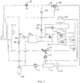
- the present disclosure provides a thermal management system for a vehicle, including a compressor 1, a first heat exchanger 2, an outdoor heat exchanger 3, a first expansion valve 4, an indoor heat exchanger 5, a first water pump 6 and an outdoor radiator 7.
- An outlet of the compressor 1 is connected to a refrigerant inlet of the first heat exchanger 2
- a refrigerant outlet of the first heat exchanger 2 is connected to an inlet of the outdoor heat exchanger 3
- an outlet of the outdoor heat exchanger 3 is connected to an inlet of the indoor heat exchanger 5 through the first expansion valve 4
- an outlet of the indoor heat exchanger 5 is connected to an inlet of the compressor 1
- a cooling liquid outlet of the first heat exchanger 2 is connected to an inlet of the outdoor radiator 7
- an outlet of the outdoor radiator 7 is connected to a cooling liquid inlet of the first heat exchanger 2
- the first water pump 6 is disposed on a flow path between the cooling liquid outlet of the first heat exchanger 2 and the inlet of the outdoor radiator 7, or the first water pump 6 is disposed on a flow path between the outlet of the outdoor radiator 7 and the cooling liquid inlet of the first heat exchanger 2.
- the above technical solution can achieve a first refrigeration mode of the thermal management system for a vehicle.
- a refrigerant can radiate heat to outside air through the outdoor radiator 7 and the outdoor heat exchanger 3 before entering the indoor heat exchanger 5.
- the high-temperature and high-pressure gaseous refrigerant discharged from the outlet of the compressor 1 flows into the first heat exchanger 2.
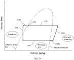
- the high-temperature and high-pressure gaseous refrigerant releases heat to low-temperature cooling liquid and loses its enthalpy (as shown by arrow 200 in FIG. 6 ), so that high-temperature cooling liquid flows out of the cooling liquid outlet of the first heat exchanger 2.
- the high-temperature cooling liquid is pumped by the first water pump 6 to flow into the outdoor radiator 7 and dissipates heat to the outside air in the outdoor radiator 7, and the low-temperature cooling liquid flowing out of the outlet of the outdoor radiator 7 returns to the first heat exchanger 2 through the cooling liquid inlet of the first heat exchanger 2 and continues to absorb the heat of the high-temperature and high-pressure gaseous refrigerant.
- the refrigerant that has released heat to the cooling liquid and lost its enthalpy flows into the refrigerant outlet of the first heat exchanger 2, and the refrigerant flows into the outdoor heat exchanger 3, releases heat to the outside in the outdoor heat exchanger 3, and continues to lose its enthalpy (as shown by arrow 300 in FIG. 6 ).
- the outdoor heat exchanger 3 serves as a condenser.
- the high-temperature and high-pressure gaseous refrigerant passes through the outdoor radiator 7 and the outdoor heat exchanger 3 in turn to release heat, then flows into the first expansion valve 4, and is throttled and depressurized by the first expansion valve 4 to become a low-temperature and low-pressure gas-liquid two-phase refrigerant.
- the low-temperature and low-pressure gas-liquid two-phase refrigerant absorbs heat in the indoor heat exchanger 5 from the air in a passenger compartment to reduce the temperature of the passenger compartment.
- the indoor heat exchanger 5 serves as an evaporator.
- the first heat exchanger 2 is disposed at the outlet of the compressor 1 and the outdoor radiator 7 is connected to the first heat exchanger 2 in the present disclosure, so that in the above first refrigeration mode of the present disclosure, the refrigerant before entering the indoor heat exchanger 5 can release heat to the outside twice through the outdoor radiator 7 and the outdoor heat exchanger 3, and the enthalpy loss and heat release of the refrigerant before entering the indoor heat exchanger 5 are greater, which is beneficial to the inflow of a lower-temperature refrigerant into the indoor heat exchanger 5, and enables the thermal management system for a vehicle provided by the present disclosure to still have a good refrigeration effect and refrigeration efficiency in a high-temperature environment to cool the passenger compartment quickly.
- the first heat exchanger 2 is disposed at the outlet of the compressor 1, and the outdoor radiator 7 is connected to the first heat exchanger 2, which can solve the problem that the refrigerant releases limited heat in the outdoor heat exchanger 3 in the high-temperature environment, and the problem that the condensing heat exchange performance is affected when the outdoor heat exchanger 3 serves as both a condenser and an evaporator.
- the thermal management system for a vehicle may further include a first flow path 8 that is selectively conducted or cut off, and a second flow path 9 that is selectively conducted or cut off.
- the refrigerant outlet of the first heat exchanger 2 is connected to the inlet of the outdoor heat exchanger 3 via the first flow path 8 and connected to the inlet of the first expansion valve 4 via the second flow path 9.
- the refrigerant outlet of the first heat exchanger 2 is connected to the inlet of the outdoor heat exchanger 3 and the inlet of the first expansion valve 4 via the first flow path 8 and the second flow path 9 respectively, the refrigerant flowing out of the refrigerant outlet of the first heat exchanger 2 can enter the indoor heat exchanger 5 via the second flow path 9 and the first expansion valve 4 in turn, without flowing through the outdoor heat exchanger 3 via the first flow path 8, and the thermal management system for a vehicle can have a second refrigeration mode.
- the first flow path 8 in the second refrigeration mode, the first flow path 8 is in a cut-off state, the second flow path 9 is in a conduction state, and the high-temperature and high-pressure gaseous refrigerant discharged from the outlet of the compressor 1 flows into the first heat exchanger 2.
- the high-temperature and high-pressure gaseous refrigerant releases heat to low-temperature cooling liquid, so that high-temperature cooling liquid flows out of the cooling liquid outlet of the first heat exchanger 2.
- the high-temperature cooling liquid is pumped by the first water pump 6 to flow into the outdoor radiator 7, and dissipates heat to the outside air in the outdoor radiator 7 to lose its enthalpy, and the low-temperature cooling liquid flowing out of the outlet of the outdoor radiator 7 returns to the first heat exchanger 2 through the cooling liquid inlet of the first heat exchanger 2 and continues to absorb the heat of the high-temperature and high-pressure gaseous refrigerant.
- the low-temperature and low-pressure gas-liquid two-phase refrigerant absorbs the heat of air in the passenger compartment in the indoor heat exchanger 5 to reduce the temperature of the passenger compartment.
- the indoor heat exchanger 5 serves as an evaporator.
- the difference between the first refrigeration mode and the second refrigeration mode lies in that: in the first refrigeration mode, the refrigerant loses its enthalpy through the outdoor heat exchanger 3 and the outdoor radiator 7 before entering the indoor heat exchanger 5 (as shown by arrows 200 and 300 in FIG. 6 ); in the second refrigeration mode, the refrigerant does not flow through the outdoor heat exchanger 3 before entering the indoor heat exchanger 5, and the refrigerant loses its enthalpy through the outdoor radiator 7 (as shown by arrow 200 in FIG.
- the thermal management system for a vehicle may be in the first refrigeration mode.
- the thermal management system for a vehicle may be in the second refrigeration mode. That is, the thermal management system for a vehicle may choose to adopt the first refrigeration mode or the second refrigeration mode according to the temperature of the external environment to cool the passenger compartment.
- the first flow path 8 is provided with a first cut-off valve 26, and the second flow path 9 is provided with a second cut-off valve 27.
- the first flow path 8 and the second flow path 8 can be conducted or cut off by controlling the opening and closing of the first cut-off valve 26 and the second cut-off valve 27.
- the thermal management system for a vehicle may further include a first three-way valve 28, the first three-way valve 28 is located on both the first flow path 8 and the second flow path 9, an A port of the first three-way valve 28 is connected to the refrigerant outlet of the first heat exchanger 2, a B port of the first three-way valve 28 is connected to the inlet of the outdoor heat exchanger 3, and a C port of the first three-way valve 28 is connected to the inlet of the first expansion valve 4.
- the first flow path 8 and the second flow path 9 can be conducted or cut off by controlling the conduction of the corresponding ports of the first three-way valve 28.
- the first flow path 8 can be conducted, and the second flow path 9 can be cut off; when the A port and C port of the first three-way valve 28 are conducted, the first flow path 8 can be cut off, and the second flow path 9 can be conducted.
- the thermal management system for a vehicle further includes an indoor air heater 10, a first throttling flow path 11, a first through flow path 12, a third flow path 13 that is selectively conducted or cut off, a fourth flow path 14 that is selectively conducted or cut off, and a first one-way valve 15.
- the cooling liquid outlet of the first heat exchanger 2 is connected to the inlet of the outdoor radiator 7 and an inlet of the indoor air heater 10 through the first water pump 6, the cooling liquid outlet of the first heat exchanger 2 is selectively connected to the inlet of the outdoor radiator 7 and the inlet of the indoor air heater 10, and an outlet of the indoor air heater 10 is connected to the cooling liquid inlet of the first heat exchanger 2;
- the outlet of the indoor heat exchanger 5 is connected to an inlet of the first one-way valve 15 and connected to the inlet of the compressor 1 via the third flow path 13
- an outlet of the first flow path 8 and an outlet of the first one-way valve 15 are both selectively connected to the inlet of the outdoor heat exchanger 3 via the first throttling flow path 11 or the first through flow path 12, and the outlet of the outdoor heat exchanger 3 is also connected to the inlet of the compressor 1 via the fourth flow path 14.
- the cooling liquid flowing out of the outlet of the indoor heat exchanger 5 can choose to return to the compressor 1 via the third flow path 13, or to flow into the outdoor heat exchanger 3 via the first one-way valve 15 and the first throttling flow path 11; since the outlet of the outdoor heat exchanger 3 is connected to the inlet of the indoor heat exchanger 5 via the first expansion valve 4, and is connected to the inlet of the compressor 1 via the fourth flow path 14 that is selectively conducted or cut off, the refrigerant flowing out of the outlet of the outdoor heat exchanger 3 can choose to flow into the indoor heat exchanger 5 via the first expansion valve 4, or to return to the compressor 1 via the fourth flow path 14.
- the thermal management system for a vehicle not only have the above-mentioned first refrigeration mode and second refrigeration mode, but also can have a heat pump heating mode and a dehumidification mode, by controlling the conduction or cut off of the first flow path 8, the second flow path 9, the third flow path 13, and the fourth flow path 14, and the conduction relationship between the cooling liquid outlet of the first heat exchanger 2 and the outdoor radiator 7 and the indoor air heater 10.
- the thermal management system for a vehicle is in the above-mentioned first refrigeration mode.
- the compressor 1, the first heat exchanger 2, the first flow path 8, the first through flow path 12, the outdoor heat exchanger 3, the first expansion valve 4, the indoor heat exchanger 5, and the third flow path 13 are connected in series to form a refrigerant loop;
- the first water pump 6, the outdoor radiator 7, and the first heat exchanger 2 are connected in series to form a cooling liquid loop; the refrigerant and the cooling liquid in the two loops exchange heat through the first heat exchanger 2.
- the refrigerant flowing out of the outlet of the indoor heat exchanger 5 cannot flow into the first flow path 8. Since the fourth flow path 14 is in the cut-off state, the refrigerant flowing out of the outlet of the outdoor heat exchanger 3 cannot return to the compressor 1 through the fourth flow path 14, but can only flow into the indoor heat exchanger 5 through the first expansion valve 4.
- the first throttling flow path 11 is in a cut-off state, that is, the refrigerant flowing out of the first flow path 8 flows into the outdoor heat exchanger 3 through the first through flow path 12, so that the refrigerant can release heat to the external environment in the outdoor heat exchanger 3.
- the thermal management system for a vehicle is in the above-mentioned second refrigeration mode.
- the compressor 1, the first heat exchanger 2, the second flow path 9, the first expansion valve 4, the indoor heat exchanger 5, and the third flow path 13 are connected in series to form a refrigerant loop;
- the first water pump 6, the outdoor radiator 7 and the first heat exchanger 2 are connected in series to form a cooling liquid loop; the refrigerant and the cooling liquid in the two loops exchange heat through the first heat exchanger 2. Since the first flow path 8 is cut off in this mode, the refrigerant flowing out of the outlet of the first heat exchanger 2 flows into the indoor heat exchanger 5 via the second flow path 9 and the first expansion valve 4, and does not pass through the outdoor heat exchanger. 3.
- the thermal management system for a vehicle may also have a first heat pump heating mode.
- the first flow path 8 is cut off, the second flow path 9 is conducted, the third flow path 13 is cut off, the fourth flow path 14 is conducted, the first through flow path 12 is cut off, the first throttling flow path 11 is conducted, and the cooling liquid outlet of the first heat exchanger 2 is connected to the indoor air heater 10, so that the compressor 1, the first heat exchanger 2, the second flow path 9, the first expansion valve 4, the indoor heat exchanger 5, the first one-way valve 15, the first throttling flow path 11, the outdoor heat exchanger 3, and the fourth flow path 14 are connected in series to form a refrigerant loop; the first water pump 6, the indoor air heater 10, and the first heat exchanger 2 are connected in series to form a cooling liquid loop; the refrigerant and the cooling liquid in the two loops exchange heat through the first heat exchanger 2.
- the high-temperature and high-pressure gaseous refrigerant discharged from the outlet of the compressor 1 flows into the first heat exchanger 2.
- the high-temperature and high-pressure gaseous refrigerant releases heat to low-temperature cooling liquid and loses its enthalpy (as shown by arrow 200 in FIG. 10 ), so that high-temperature cooling liquid flows out of the cooling liquid outlet of the first heat exchanger 2.
- the high-temperature cooling liquid is pumped by the first water pump 6 to flow into the indoor air heater 10, and releases heat to the passenger compartment through the indoor air heater 10 to increase the temperature of the passenger compartment.
- Low-temperature cooling liquid flowing out of the outlet of the indoor air heater 10 returns to the first heat exchanger 2 through the cooling liquid inlet of the first heat exchanger 2, and continues to absorb the heat of the high-temperature and high-pressure gaseous refrigerant.
- the refrigerant that has released heat to the cooling liquid and lost its enthalpy flows into the refrigerant outlet of the first heat exchanger 2, and the refrigerant flows into the indoor heat exchanger 5 after being throttled and depressurized by the first expansion valve 4, and releases heat to the passenger compartment in the indoor heat exchanger 5 to lose its enthalpy (as shown by arrow 500 in FIG. 10 ).
- the indoor heat exchanger 5 serves as a condenser.
- the refrigerant flowing out of the outlet of the indoor heat exchanger 5 flows into the outdoor heat exchanger 3 after being throttled and depressurized by the first throttling flow path 11 (as shown by arrow 330 in FIG. 10 ).
- the low-pressure gas-liquid two-phase mixed refrigerant absorbs heat from outside air, which increases the enthalpy value of the refrigerant (as shown by arrow 300 in FIG. 10 ), and finally the refrigerant returns to the compressor 1.
- the indoor heat exchanger 5 and the indoor air heater 10 arranged in the passenger compartment both release heat to the air in the passenger compartment.
- the indoor heat exchanger 5 may be arranged behind the indoor air heater 10, and air flows through the indoor heat exchanger 5 and then through the indoor air heater 10. As such, the indoor heat exchanger 5 can preheat the air that is about to flow through the indoor air heater 10.
- the refrigerant needs to be throttled and depressurized by the first expansion valve 4 before entering the indoor heat exchanger 5, in order to adjust the temperature of the refrigerant that is about to enter the indoor heat exchanger 5 through the opening of the first expansion valve 4, so that the temperature of the refrigerant flowing into the indoor heat exchanger 5 is higher than the environmental temperature in the passenger compartment and lower than the temperature of the cooling liquid in the indoor air heater 10.
- the refrigerant in the indoor heat exchanger 5 can not only release heat (rather than absorb heat) to the passenger compartment, but also heat the air flowing through the indoor heat exchanger 5 to be not higher than the temperature of the cooling liquid in the indoor air heater 10, so as to realize the above pre-heating function and prevent the cooling liquid in the indoor air heater 10 from releasing heat to the air flowing through the indoor air heater 10.
- the air heater is a main heat source for providing heat to the passenger compartment
- the indoor heat exchanger 5 is an auxiliary heat source that assists in providing heat to the passenger compartment.
- the temperature of the refrigerant entering the indoor heat exchanger 5 can be adjusted by adjusting the opening of the first expansion valve 4, so that the temperature of the refrigerant in the indoor heat exchanger 5 has a temperature difference from the temperature of the cooling liquid in the indoor air heater 10, which can achieve the function of preheating, by the indoor heat exchanger 5, the air that is about to flow through the indoor air heater 10.
- the thermal management system for a vehicle may further have a second heat pump heating mode.
- the first flow path 8 is conducted, the second flow path 9 is cut off, the third flow path 13 is cut off, the fourth flow path 14 is conducted, the first through flow path 12 is cut off, the first throttling flow path 11 is cut off, and the cooling liquid outlet of the first heat exchanger 2 is connected to the indoor air heater 10, so that the compressor 1, the first heat exchanger 2, the first flow path 8, the first throttling flow path 11, and the outdoor heat exchanger 3 are connected in series to form a refrigerant loop; the first water pump 6, the indoor air heater 10, and the first heat exchanger 2 are connected in series to form a cooling liquid loop; the refrigerant and the cooling liquid in the two loops exchange heat through the first heat exchanger 2.
- the high-temperature and high-pressure gaseous refrigerant discharged from the outlet of the compressor 1 flows into the first heat exchanger 2.
- the high-temperature and high-pressure gaseous refrigerant releases heat to low-temperature cooling liquid and loses its enthalpy (as shown by arrow 200 in FIG. 12 ), so that high-temperature cooling liquid flows out of the cooling liquid outlet of the first heat exchanger 2.
- the high-temperature cooling liquid is pumped by the first water pump 6 to flow into the indoor air heater 10, and releases heat to the passenger compartment through the indoor air heater 10 to increase the temperature of the passenger compartment.
- Low-temperature cooling liquid flowing out of the outlet of the indoor air heater 10 returns to the first heat exchanger 2 through the cooling liquid inlet of the first heat exchanger 2, and continues to absorb the heat of the high-temperature and high-pressure gaseous refrigerant.
- the refrigerant that has released heat to the cooling liquid and lost its enthalpy flows into the refrigerant outlet of the first heat exchanger 2, the refrigerant is throttled and depressurized by the first expansion valve 4 to become a low-pressure gas-liquid two-phase mixed refrigerant (as shown by arrow 330 in FIG.
- the low-pressure gas-liquid two-phase mixed refrigerant flows into the outdoor heat exchanger 3, and absorbs heat from outside air in the outdoor heat exchanger 3 to obtain an enthalpy (as shown by arrow 300 in FIG. 11 ).
- the outdoor heat exchanger 3 serves as an evaporator.
- the refrigerant flowing out of the outdoor heat exchanger 3 returns to the compressor 1.
- the difference between the first heat pump heating mode and the second heat pump heating mode lies in that: in the first heat pump heating mode, the refrigerant flowing out of the refrigerant outlet of the first heat exchanger 2 is throttled and depressurized by the first expansion valve 4 and then flows into the indoor heat exchanger 5, the refrigerant in the indoor heat exchanger 5 and the refrigerant in the indoor air heater 10 both release heat to the passenger compartment, and the refrigerant in the indoor heat exchanger 5 can preheat the air that is about to flow through the indoor air heater 10; in the second heat pump heating mode, the refrigerant flowing out of the refrigerant outlet of the first heat exchanger 2 does not flow into the indoor heat exchanger 5, but returns to the compressor 1 via the outdoor heat exchanger 3; that is, both the indoor heat exchanger 5 and the indoor air heater 10 are used to release heat to the passenger compartment in the first heat pump heating mode, and only the indoor air heater 10 is used to release heat to the passenger compartment in the second heat pump heating mode.
- the refrigerant in the indoor heat exchanger 5 can preheat the air that is about to flow through the indoor air heater 10 in the first heat pump heating mode, but no refrigerant flows through the indoor heat exchanger 5 to preheat the air that is about to flow through the indoor air heater 10 in the second heat pump heating mode, so the temperature of the air passing through the indoor air heater 10 in the first heat pump heating mode is higher than that in the second heat pump heating mode.
- the first heat pump heating mode has higher speed and effect of increasing the temperature of the passenger compartment.
- the appropriate heat pump heating mode can be selected according to the temperature of the passenger compartment or the heating demand of the passenger compartment. For example, when the passenger compartment is at a low temperature, the thermal management system for a vehicle may be in the first heat pump heating mode; and when the temperature of the passenger compartment is relatively low, the thermal management system for a vehicle may be in the second heat pump heating mode.
- the thermal management system for a vehicle may also have a first dehumidification mode.
- the first flow path 8 is cut off, the second flow path 9 is conducted, the third flow path 13 is conducted, the fourth flow path 14 is cut off, and the cooling liquid outlet of the first heat exchanger 2 is connected to the indoor air heater 10, so that the compressor 1, the first heat exchanger 2, the second flow path 9, the first expansion valve 4, the indoor heat exchanger 5 and the third flow path 13 are connected in series to form a refrigerant loop; the first water pump 6, the indoor air heater 10, and the first heat exchanger 2 are connected in series to form a cooling liquid loop; the refrigerant and the cooling liquid in the two loops exchange heat through the first heat exchanger 2.
- the refrigerant flowing out of the refrigerant outlet of the first heat exchanger 2 flows into the indoor heat exchanger 5 after being throttled and depressurized by the first expansion valve 4, the refrigerant in the indoor heat exchanger 5 absorbs heat, and the cooling liquid in the air heater releases heat to the passenger compartment.
- the hot air in the passenger compartment comes into contact with the indoor heat exchanger 5
- condensed water can be formed on the surface of the indoor heat exchanger 5 to achieve the purpose of reducing the humidity of the air in the passenger compartment, the condensed water can be discharged out of the vehicle through a draft tube.
- the air heater releases heat to the passenger compartment, so that the temperature of the passenger compartment can be stabilized within a certain range, and can be prevented from being reduced by the indoor heat exchanger 5.
- the thermal management system for a vehicle may also have a second dehumidification mode.
- the first flow path 8 is conducted, the second flow path 9 is conducted, the third flow path 13 is conducted, the fourth flow path 14 is conducted, the first throttling flow path 11 is conducted, the first through flow path 12 is cut off, and the cooling liquid outlet of the first heat exchanger 2 is connected to the indoor air heater 10, so that the compressor 1, the first heat exchanger 2, the first flow path 8, the first throttling flow path 11, the outdoor heat exchanger 3, and the fourth flow path 14 are connected in series to form a refrigerant loop; the compressor 1, the first heat exchanger 2, the second flow path 9, the first expansion valve 4, the indoor heat exchanger 5, and the third flow path 13 are connected in series to form another refrigerant loop; the first water pump 6, the indoor air heater 10, and the first heat exchanger 2 are connected in series to form a cooling liquid loop; the cooling liquid and the refrigerant flowing out of the outlet of the compressor 1 exchange
- the refrigerant flowing out of the refrigerant outlet of the first heat exchanger 2 is divided into two streams.
- One stream flows into the indoor heat exchanger 5 after being throttled and depressurized by the first expansion valve 4, so that the refrigerant in the indoor heat exchanger 5 absorbs heat from the passenger compartment.
- the other stream flows into the outdoor heat exchanger 3 after being throttled and depressurized by the first throttling flow path 11, to absorb heat from outside air in the outdoor heat exchanger 3.
- the refrigerant flowing out of the outlet of the indoor heat exchanger 5 converges with the refrigerant flowing out of the outlet of the outdoor heat exchanger 3 and then returns to the compressor 1.
- the thermal management system for a vehicle may also have a third dehumidification mode.
- the first flow path 8 is cut off, the second flow path 9 is conducted, the third flow path 13 is cut off, the fourth flow path 14 is conducted, the first throttling flow path 11 is conducted, the first through flow path 12 is cut off, and the cooling liquid outlet of the first heat exchanger 2 is connected to the indoor air heater 10, so that the compressor 1, the first heat exchanger 2, the second flow path 9, the first expansion valve 4, the indoor heat exchanger 5, the first throttling flow path 11, the outdoor heat exchanger 3, and the fourth flow path 14 are connected in series to form a refrigerant loop; the first water pump 6, the indoor air heater 10, and the first heat exchanger 2 are connected in series to form a cooling liquid loop; the refrigerant and the cooling liquid in the two loops exchange heat in the first heat exchanger 2.
- the difference between the third dehumidification mode and the first dehumidification mode lies in that: in the first dehumidification mode, the refrigerant flowing out of the indoor heat exchanger 5 does not pass through the outdoor heat exchanger 3, but directly returns to the compressor through the third flow path 13; in the third dehumidification mode, the refrigerant flowing out of the indoor heat exchanger 5 does not flow into the third flow path 13, but flows into the outdoor heat exchanger 3 through the first throttling flow path 11, absorbs heat from the outside air via the outdoor heat exchanger 3, and then returns to the compressor 1.
- the thermal management system for a vehicle may also have a fourth dehumidification mode.
- the first flow path 8 is conducted, the second flow path 9 is cut off, the third flow path 13 is conducted, the fourth flow path 14 is cut off, the first throttling flow path 11 is conducted, the first through flow path 12 is cut off, and the cooling liquid outlet of the first heat exchanger 2 is connected to the indoor air heater 10, so that the compressor 1, the first heat exchanger 2, the first flow path 8, the first throttling flow path 11, the outdoor heat exchanger 3, the first expansion valve 4, the indoor heat exchanger 5, and the third flow path 13 are connected in series to form a refrigerant loop; the first water pump 6, the indoor air heater 10, and the first heat exchanger 2 are connected in series to form a cooling liquid loop; the refrigerant and the cooling liquid in the two loops exchange heat in the first heat exchanger 2.
- the fourth dehumidification mode differs from the second dehumidification mode and the third dehumidification mode in that, in the fourth dehumidification mode, the refrigerant flowing out of the refrigerant outlet of the first heat exchanger 2 first passes through the outdoor heat exchanger 3 to exchange heat with the outside air in the outdoor heat exchanger 3, then is throttled and pressurized by the first expansion valve 4, and flows into the indoor heat exchanger 5.
- the degrees of throttling of the first throttling flow path 11 and the first expansion valve 4 on the refrigerant affect each other, and the control complexity of the thermal management system for a vehicle is relatively high.
- the degrees of throttling of the first throttling flow path 11 and the first expansion valve 4 on the refrigerant do not affect each other, and the control complexity of the thermal management system for a vehicle is relatively low.
- the thermal management system for a vehicle may be in the first dehumidification mode, the second dehumidification mode, the third dehumidification mode, or the fourth dehumidification mode according to the environmental temperature.
- the first dehumidification mode may be used for dehumidification
- the second dehumidification mode may be used for dehumidification
- the third dehumidification mode and the fourth dehumidification mode may be used for dehumidification.
- the third flow path 13 may be provided with a third cut-off valve 29, and the fourth flow path 14 may be provided with a fourth cut-off valve 30.
- the third flow path 13 and the fourth flow path 14 are conducted or cut off by controlling the opening and closing of the third cut-off valve 29 and the fourth cut-off valve 30.
- the third flow path 13 and the fourth flow path 14 may also be provided with switch valves, respectively.
- the first through flow path 12 directly conducts the refrigerant (that is, without throttling).
- the first throttling flow path 11 may be provided with a third expansion valve 31
- the first through flow path 12 may be provided with a fifth cut-off valve 32
- the third expansion valve 31 is parallel to the fifth cut-off valve 32.
- the thermal management system for a vehicle may further include an expansion switch valve 33, the outlet of the first flow path 8 and the outlet of the first one-way valve 15 are both connected to an inlet of the expansion switch valve 33, an outlet of the expansion switch valve 33 is connected to the inlet of the outdoor heat exchanger 3, the first throttling flow path 11 is a throttling flow channel of the expansion switch valve 33, and the first through flow path 12 is a through flow channel of the expansion switch valve 33.
- the expansion switch valve 33 is equivalent to an integration of an expansion valve and a switch valve, the expansion switch valve 33 has a throttling flow channel and a through flow channel inside, a throttling valve port and a throttling valve core are disposed in the throttling flow channel, and a through valve port and a through valve core are disposed in the through flow channel.
- the opening of the throttling valve core or the through valve core can be selectively controlled according to the operating mode of the thermal management system for a vehicle, so that the refrigerant passing through the expansion switch valve 33 has a throttling state in which the refrigerant is throttled and depressurized and a through flow state in which the refrigerant is not throttled but directly conducted.
- the thermal management system for a vehicle further includes a second three-way valve, an A port of the second three-way valve is connected to the outlet of the first water pump 6, a B port of the second three-way valve is connected to the inlet of the outdoor radiator 7, and a C port of the second three-way valve is connected to the inlet of the indoor air heater 10.
- the thermal management system for a vehicle further includes a sixth cut-off valve 35 and a seventh cut-off valve 36, and the outlet of the first water pump 6 is connected to the inlet of the outdoor radiator 7 via the sixth cut-off valve 35 and connected to the inlet of the indoor air heater 10 via the seventh cut-off valve 36.
- the sixth cut-off valve 35 is opened, the first water pump 6 is opened, and the seventh cut-off valve 36 is closed, the flow path between the cooling liquid outlet of the first heat exchanger 2 and the outdoor radiator 7 can be conducted.
- the cut-off valve 36 is opened, the first water pump 6 is opened, and the sixth cut-off valve 35 is closed, the flow path between the cooling liquid outlet of the first heat exchanger 2 and the indoor air heater 10 can be conducted.
- the thermal management system for a vehicle provided by the present disclosure further includes a first gas-liquid separation device 22, the outlet of the fourth flow path 14 is connected to an inlet of the first gas-liquid separation device 22, and the inlet of the compressor 1 is connected to a gas outlet of the first gas-liquid separation device 22 and the outlet of the third flow path 13.
- the gas-liquid separation device is usually disposed at the inlet of the compressor, and the refrigerant returning to the compressor must pass through the gas-liquid separation device before returning to the compressor, which will increase the control complexity of the thermal management system for a vehicle.
- the outlet of the fourth flow path 14 is connected to the inlet of the first gas-liquid separation device 22, and the inlet of the compressor 1 is connected to the gas outlet of the first gas-liquid separation device 22 and the outlet of the third flow path 13, the refrigerant flowing out of the outdoor heat exchanger 3 is separated into a gaseous refrigerant and a liquid refrigerant by the first gas-liquid separation device 22, and the refrigerant flowing out of the outlet of the indoor heat exchanger 5 will bypass the first gas-liquid separation device 22, that is, does not pass through the first gas-liquid separation device 22 but directly returns to the compressor 1, which will reduce the control complexity of the thermal management system for a vehicle.
- the gas-liquid separation device functions to separate the refrigerant that is about to enter the compressor into a gaseous refrigerant and a liquid refrigerant, and only the gaseous refrigerant returns to the compressor, so as to prevent the liquid refrigerant from entering the compressor to cause liquid shock of the compressor.
- the refrigerant is soluble with lubricating oil in the compressor, that is, the refrigerant will carry the lubricating oil in the compressor after passing through the compressor. If the degree of superheat of the refrigerant entering the compressor is less than 0, the liquid refrigerant will enter the compressor to cause liquid shock. If the degree of superheat is greater than 0, the refrigerant entering the compressor will carry less lubricating oil.
- the temperature of the refrigerant at the inlet of the compressor is different.
- the temperature of the refrigerant at the inlet of the compressor in refrigeration mode is higher than that in the heating mode, that is, the specific volume of the refrigerant at the inlet of the compressor in the refrigeration mode is smaller than that in the heating mode. Since the specific volume is inversely proportional to the density, the density of the refrigerant at the inlet of the compressor in the refrigeration mode will be greater than that in the heating mode.
- the mass flow of the refrigerant at the inlet of the compressor in the refrigeration mode is greater than that in the heating mode, that is, the refrigerant entering the compressor carries more lubricating oil in the refrigeration mode than in the heating mode, which will not cause abnormal lubrication of the compressor. That is, in the refrigeration mode, the degree of superheat of the refrigerant that is about to flow into the compressor may not be controlled to be exactly equal to zero.
- the outlet of the outdoor heat exchanger 3 is connected to the inlet of the compressor 1 through the first gas-liquid separation device 22, while the outlet of the indoor heat exchanger 5 is directly connected to the inlet of the compressor 1 without depending on the first gas-liquid separation device 22.
- the refrigerant flowing out of the outlet of the indoor heat exchanger 5 returns to the compressor 1 without passing through the first gas-liquid separation device 22, that is, in the first refrigeration mode and the second refrigeration mode, the degree of superheat of the refrigerant at the inlet of the compressor 1 is not controlled, which can reduce the control difficulty and control complexity of the thermal management system for a vehicle.
- the thermal management system for a vehicle may further include a second gas-liquid separation device 25, the refrigerant outlet of the first heat exchanger 2 is connected to an inlet of the second gas-liquid separation device 25, and a liquid outlet of the second gas-liquid separation device 25 is connected to the inlets of the first flow path 8 and the second flow path 9.
- the second gas-liquid separation device 25 performs gas-liquid separation on the gas-liquid two-phase mixed refrigerant flowing out of the refrigerant outlet of the first heat exchanger 2, so that the liquid refrigerant flows into the first flow path 8 and the second flow path 9.
- the thermal management system for a vehicle may further include a third heat exchanger 23, the outlet of the second flow path 9 and the outlet of the outdoor heat exchanger 3 are both connected to a first refrigerant inlet of the third heat exchanger 23, a first refrigerant outlet of the third heat exchanger 23 is connected to the inlet of the indoor heat exchanger 5 through the first expansion valve 4, the outlet of the third flow path 13 is connected to a second refrigerant inlet of the third heat exchanger 23, and a second refrigerant outlet of the third heat exchanger 23 is connected to the inlet of the compressor 1; or, the outlet of the outdoor heat exchanger 3 is connected to the first refrigerant inlet of the third heat exchanger 23, the inlet of the first expansion valve 4 is connected to the first refrigerant outlet of the third heat exchanger 23 and the outlet of the second flow path 9, the outlet of the third flow path 13 is connected to the second refrigerant inlet of the third heat exchanger 23, and the second refrigerant outlet of the third heat exchanger 23 is connected to
- the refrigerant that is about to flow into the indoor heat exchanger 5 through the first expansion valve 4 can exchange heat in the third heat exchanger 23 with the refrigerant flowing out of the indoor heat exchanger 5, and the refrigerant flowing out of the indoor heat exchanger 5 absorbs heat in the third heat exchanger 23 from the refrigerant that is about to flow into the indoor heat exchanger 5 through the first expansion valve 4, so that air can be supplemented to increase enthalpy before the refrigerant flowing out of the indoor heat exchanger 5 returns to the compressor 1.
- the temperature of the refrigerant flowing out of the indoor heat exchanger 5 is approximately equal to the desired refrigeration temperature of the passenger compartment
- the temperature of the refrigerant flowing out of the outdoor heat exchanger 3 is approximately equal to the temperature of the external environment
- the temperature of the external environment is higher than the desired refrigeration temperature of the passenger compartment, so in the first refrigeration mode and the fourth dehumidification mode, the temperature of the refrigerant flowing out of the outdoor heat exchanger 3 is higher than that of the refrigerant flowing out of the indoor heat exchanger 5. Therefore, the refrigerant flowing out of the outdoor heat exchanger 3 can release heat to the refrigerant flowing out of the indoor heat exchanger 5 in the third heat exchanger 23.
- the temperature of the refrigerant after releasing heat in the first heat exchanger 2 is higher than that of the refrigerant flowing out of the indoor heat exchanger 5, so in the second refrigeration mode, the first dehumidification mode and the second dehumidification mode, the refrigerant flowing out of the first heat exchanger 2 can release heat to the refrigerant flowing out of the indoor heat exchanger 5 in the third heat exchanger 23.
- vehicle manufacturers seek to continuously shorten the charging time of a battery pack 18 when designing electric vehicles, and the shortening of the charging time of the battery pack 18 means that the battery pack 18 emits more heat during charging, and the temperature of the battery pack 18 is higher.
- the battery pack 18 needs to be cooled quickly to shorten the charging time of the battery pack 18 while keeping the temperature of the battery pack 18 moderately within its suitable working temperature range.
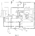
- the thermal management system for a vehicle provided by the present disclosure may further include a second heat exchanger 16, a second expansion valve 17, a battery pack 18 and a second water pump 19.
- the outlet of the outdoor heat exchanger 3 and the outlet of the second flow path 9 are both connected to a refrigerant inlet of the second heat exchanger 16 through the second expansion valve 17, and a refrigerant outlet of the second heat exchanger 16 is connected to the inlet of the compressor 1; a first cooling liquid outlet of the second heat exchanger 16 is connected to an inlet of the battery pack 18, an outlet of the battery pack 18 is connected to a first cooling liquid inlet of the second heat exchanger 16, and the second water pump 19 is disposed on the flow path between the first cooling liquid outlet of the second heat exchanger 16 and the inlet of the battery pack 18, or the second water pump 19 is disposed on the flow path between the outlet of the battery pack 18 and the first cooling liquid inlet of the second heat exchanger 16.
- the thermal management system for a vehicle may have a first battery pack 18 cooling mode.
- the first flow path 8 is conducted, the second flow path 9 is cut off, the third flow path 13 is cut off, the fourth flow path 14 is cut off, the first through flow path 12 is conducted, the first throttling flow path 11 is cut off, the first expansion valve 4 is closed, the second expansion valve 17 is opened, the second water pump 19 is opened, and the cooling liquid outlet of the first heat exchanger 2 is connected to the outdoor radiator 7, so that the compressor 1, the first heat exchanger 2, the first flow path 8, the first through flow path 12, the outdoor heat exchanger 3, the second expansion valve 17, the second heat exchanger 16, and the compressor 1 are connected in series to form a refrigerant loop; the first water pump 6, the outdoor radiator 7, and the first heat exchanger 2 are connected in series to form a cooling liquid loop; the second water pump 19, the battery pack 18 and the second heat exchanger 16 are connected in series to form another cooling liquid loop; and the two cooling
- the high-temperature and high-pressure gaseous refrigerant discharged from the outlet of the compressor 1 flows into the first heat exchanger 2.
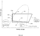
- the high-temperature and high-pressure gaseous refrigerant releases heat to low-temperature cooling liquid and loses its enthalpy (as shown by arrow 200 in FIG. 22 ), so that high-temperature cooling liquid flows out of the cooling liquid outlet of the first heat exchanger 2.
- the high-temperature cooling liquid is pumped by the first water pump 6 to flow into the outdoor radiator 7 and dissipates heat to the outside air in the outdoor radiator 7, and the low-temperature cooling liquid flowing out of the outlet of the outdoor radiator 7 returns to the first heat exchanger 2 through the cooling liquid inlet of the first heat exchanger 2 and continues to absorb the heat of the high-temperature and high-pressure gaseous refrigerant.
- the refrigerant that has released heat to the cooling liquid and lost its enthalpy flows into the refrigerant outlet of the first heat exchanger 2, and the refrigerant flows into the outdoor heat exchanger 3, releases heat to the outside in the outdoor heat exchanger 3, and continues to lose its enthalpy (as shown by arrow 300 in FIG. 21 ).
- the outdoor heat exchanger 3 serves as a condenser.
- the high-temperature and high-pressure gaseous refrigerant sequentially passes through the outdoor radiator 7 and the outdoor heat exchanger 3 to release heat, then flows into the second expansion valve 17, and is throttled and depressurized by the second expansion valve 17 to become a low-temperature and low-pressure gas-liquid two-phase refrigerant.
- the low-temperature and low-pressure gas-liquid two-phase refrigerant absorbs the heat of the cooling liquid in the second heat exchanger 16, so that low-temperature cooling liquid flows out of the first cooling liquid outlet of the second heat exchanger 16, wherein the low-temperature cooling liquid is used to absorb the heat of the battery pack 18 to cool the battery pack 18.
- the thermal management system for a vehicle may have a second battery pack 18 cooling mode.
- the first flow path 8 is cut off, the second flow path 9 is conducted, the third flow path 13 is cut off, the fourth flow path 14 is cut off, the first expansion valve 4 is closed, the second expansion valve 17 is opened, the second water pump 19 is opened, and the cooling liquid outlet of the first heat exchanger 2 is connected to the outdoor radiator 7, so that the compressor 1, the first heat exchanger 2, the second flow path 9, the second expansion valve 17, and the second heat exchanger 16 are connected in series to form a refrigerant loop; the first water pump 6, the outdoor radiator 7, and the first heat exchanger 2 are connected in series to form a cooling liquid loop; the second water pump 19, the battery pack 18 and the second heat exchanger 16 are connected in series to form another cooling liquid loop; and the two cooling liquid loops exchange heat with the refrigerant loop through the first heat exchanger 2 and the second heat exchanger 16 respecti vel y.
- the high-temperature and high-pressure gaseous refrigerant discharged from the outlet of the compressor 1 flows into the first heat exchanger 2.
- the high-temperature and high-pressure gaseous refrigerant releases heat to low-temperature cooling liquid, so that high-temperature cooling liquid flows out of the cooling liquid outlet of the first heat exchanger 2.
- the high-temperature cooling liquid is pumped by the first water pump 6 to flow into the outdoor radiator 7, dissipates heat to the outside air in the outdoor radiator 7 and loses its enthalpy (as shown by arrow 200 in FIG.
- the difference between the first battery pack 18 cooling mode and the second battery pack 18 cooling mode lies in that: in the first battery pack 18 cooling mode, the refrigerant loses its enthalpy through the outdoor heat exchanger 3 and the outdoor radiator 7 before entering the second heat exchanger 16 (as shown by arrows 200 and 300 in FIG. 22 ); in the second battery pack 18 cooling mode, the refrigerant does not flow through the outdoor heat exchanger 3 before entering the second heat exchanger 16, and the refrigerant loses its enthalpy through the outdoor radiator 7 (as shown by arrow 200 in FIG.
- the thermal management system for a vehicle may be in the first battery pack 18 cooling mode.
- the thermal management system for a vehicle may be in the second battery pack 18 cooling mode. That is, the thermal management system for a vehicle may choose to use the first battery pack 18 cooling mode or the second battery pack 18 cooling mode to cool the battery pack 18 according to the current temperature of the battery pack 18.
- the first battery pack 18 cooling mode or the second battery pack 18 cooling mode may also be selected according to the heating rate of the battery pack 18.
- the first battery pack 18 cooling mode may be selected to cool the battery pack 18.
- the second cooling mode may be selected to cool the battery pack 18.
- the thermal management system for a vehicle may also have a first passenger compartment refrigeration and battery pack 18 cooling mode.
- This mode is a hybrid mode of the first refrigeration mode and the first battery pack 18 cooling mode described above.
- the refrigerant flowing out of the outlet of the outdoor heat exchanger 3 is divided into two streams, one is throttled and depressurized by the first expansion valve 4 and then enters the indoor heat exchanger 5, and the other is throttled and depressurized by the second expansion valve 17 and then enters the second heat exchanger 16.
- the principle of the first passenger compartment refrigeration and battery pack 18 cooling mode is similar to the principles of the first refrigeration mode and the first battery pack 18 cooling mode, so details are not described herein again.
- the thermal management system for a vehicle may also have a second passenger compartment refrigeration and battery pack 18 cooling mode.
- This mode is a hybrid mode of the second refrigeration mode and the second battery pack 18 cooling mode described above.
- the refrigerant flowing out of the refrigerant outlet of the first heat exchanger 2 is divided into two streams, one is throttled and depressurized by the first expansion valve 4 and then enters the indoor heat exchanger 5, and the other is throttled and depressurized by the second expansion valve 17 and then enters the second heat exchanger 16.
- the principle of the second passenger compartment refrigeration and battery pack 18 cooling mode is similar to the principles of the second refrigeration mode and the second battery pack 18 cooling mode, so details are not described herein again.
- the thermal management system for a vehicle further includes the electronic device 20 and a third water pump 21, the second cooling liquid outlet of the second heat exchanger 16 is connected to an inlet of the electronic device 20, an outlet of the electronic device 20 is connected to the second cooling liquid inlet of the second heat exchanger 16, and the third water pump 21 is disposed on the flow path between the second cooling liquid outlet of the second heat exchanger 16 and the inlet of the electronic device 20, or the third water pump 21 is disposed on the flow path between the outlet of the electronic device 20 and the second cooling liquid inlet of the second heat exchanger 16.
- the waste heat of the electronic device 20 can be recovered into the refrigerant loop through the second heat exchanger 16.
- the electronic device 20 refers to a device that operates by means of electricity and generates heat during the operation.
- the electronic device 20 may include at least one of a motor, a charger, a motor controller, and a DC-DC converter.
- the thermal management system for a vehicle may have a heat recovery mode.
- the high-temperature cooling liquid in the indoor air heater 10 releases heat to the passenger compartment to achieve heating of the passenger compartment, and the waste heat of the electronic device 20 is recovered into the refrigerant loop for increasing enthalpy and supplementing gas for the refrigerant at the inlet of the compressor 1.
- the first flow path 8 is cut off, the second flow path 9 is conducted, the third flow path 13 is cut off, the fourth flow path 14 is cut off, the first expansion valve 4 is closed, the second expansion valve 17 is opened, the third water pump 21 is opened, and the cooling liquid outlet of the first heat exchanger 2 is connected to the indoor air heater 10, so that the compressor 1, the first heat exchanger 2, the second flow path 9, the second expansion valve 17, and the second heat exchanger 16 are connected in series to form a refrigerant loop; the first water pump 6, the outdoor radiator 7, and the first heat exchanger 2 are connected in series to form a cooling liquid loop; the third water pump 21, the electronic device 20, and the second heat exchanger 16 are connected in series to form another cooling liquid loop; and the two cooling liquid loops exchange heat with the refrigerant loop through the first heat exchanger 2 and the second heat exchanger 16 respectively.
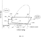
- the refrigerant exchanges heat in the second heat exchanger 16 with the cooling liquid that absorbs heat from the electronic device 20, to absorb the heat of the cooling liquid, so that the enthalpy-increased refrigerant flows out of the refrigerant outlet of the second heat exchanger 16 (as shown by arrow 160 in FIG. 30 ), to achieve the purposes of increasing enthalpy and supplementing gas for the refrigerant at the inlet of the compressor 1.
- the thermal management system for a vehicle may have a first heat pump and heat recovery mode.
- the high-temperature cooling liquid in the indoor air heater 10 and the cooling liquid in the indoor heat exchanger 5 both release heat to the passenger compartment, and the waste heat of the electronic device 20 is recovered into the refrigerant loop for increasing enthalpy and supplementing gas for the refrigerant at the inlet of the compressor 1.
- the first flow path 8 is cut off, the second flow path 9 is conducted, the third flow path 13 is cut off, the fourth flow path 14 is conducted, the first through flow path 12 is cut off, the first throttling flow path 11 is conducted, the first expansion valve 4 is opened, the second expansion valve 17 is opened, the third water pump 21 is opened, and the cooling liquid outlet of the first heat exchanger 2 is connected to the indoor air heater 10, so that the compressor 1, the first heat exchanger 2, the second flow path 9, the first expansion valve 4, the indoor heat exchanger 5, the first one-way valve 15, the first throttling flow path 11, the outdoor heat exchanger 3, and the fourth flow path 14 are connected in series to form a refrigerant loop; the first water pump 6, the indoor air heater 10, and the first heat exchanger 2 are connected in series to form a cooling liquid loop; the third water pump 21, the electronic device 20, and the second heat exchanger 16 are connected in series to form another cooling liquid loop; and the two cooling liquid loops exchange heat with the refrigerant loop through the first heat exchanger 2 and the second
- the first heat pump and heat recovery mode is similar to the first heat pump heating mode mentioned above. The difference is that in the first heat pump and heat recovery mode, the third water pump 21 and the second expansion valve 17 are both opened, so that the refrigerant can exchange heat in the second heat exchanger 16 with the cooling liquid that absorbs heat from the electronic device 20 to absorb the heat of the cooling liquid, and the enthalpy-increased refrigerant flows out of the refrigerant outlet of the second heat exchanger 16.
- the difference between the first heat pump and heat recovery mode and the heat recovery mode lies in that, in the first heat pump and heat recovery mode, the first expansion valve 4 is opened, and the opening of the first expansion valve 4 is adjusted such that the refrigerant flows into the indoor heat exchanger 5 and releases heat to the passenger compartment in the indoor heat exchanger 5 to preheat the air that is about to flow through the indoor air heater 10.
- the thermal management system for a vehicle may have a second heat pump and heat recovery mode.
- the first flow path 8 is conducted, the second flow path 9 is conducted, the third flow path 13 is conducted, the fourth flow path 14 is conducted, the first throttling flow path 11 is conducted, the first through flow path 12 is cut off, the first expansion valve 4 is closed, the second expansion valve 17 is opened, the third water pump 21 is opened, and the cooling liquid outlet of the first heat exchanger 2 is connected to the indoor air heater 10, so that the compressor 1, the first heat exchanger 2, the first flow path 8, the first throttling flow path 11, the outdoor heat exchanger 3, and the fourth flow path 14 are connected in series to form a refrigerant loop; the compressor 1, the first heat exchanger 2, the second flow path 9, the second expansion valve 17, and the second heat exchanger 16 are connected in series to form another refrigerant loop; the first water pump 6, the indoor air heater 10, and the first heat exchanger 2 are connected in series to form a cooling liquid loop; and
- the cooling liquid flowing out of the refrigerant outlet of the first heat exchanger 2 is divided into two streams, one flows into the second heat exchanger 16 through the second expansion valve 17 and absorbs the heat of the electronic device 20 in the second heat exchanger 16 to increase the enthalpy of the refrigerant at the inlet of the compressor 1, and the other flows into the outdoor heat exchanger 3 through the first throttling flow path 11 and absorbs the heat of the outside air in the outdoor heat exchanger 3 to increase the enthalpy of the refrigerant.
- the thermal management system for a vehicle may also have a third heat pump and heat recovery mode.
- the first flow path 8 is conducted, the second flow path 9 is cut off, the third flow path 13 is cut off, the fourth flow path 14 is cut off, the first throttling flow path 11 is conducted, the first through flow path 12 is cut off, the first expansion valve 4 is closed, the second expansion valve 17 is opened, the third water pump 21 is opened, and the cooling liquid outlet of the first heat exchanger 2 is connected to the indoor air heater 10, so that the compressor 1, the first heat exchanger 2, the first flow path 8, the first throttling flow path 11, the outdoor heat exchanger 3, the second expansion valve 17, and the second heat exchanger 16 are connected in series to form a refrigerant loop; the first water pump 6, the indoor air heater 10, and the first heat exchanger 2 are connected in series to form a cooling liquid loop; the third water pump 21, the electronic device 20, and the second heat exchanger 16 are connected in series to form another cooling liquid loop; and the cooling
- the refrigerant flowing out of the outlet of the outdoor heat exchanger 3 does not directly return to the compressor 1, but first flows through the second heat exchanger 16, absorbs heat in the second heat exchanger 16 from the cooling liquid which has absorbed heat from the electronic device 20 to increase enthalpy and supplement gas, and then returns to the compressor 1, which is conducive to improving the heating capacity of the passenger compartment in a low-temperature environment (when the external environmental heat absorbed by the refrigerant at the outdoor heat exchanger 3 is limited).
- the outlet of the fourth flow path 14 is connected to the inlet of the first gas-liquid separation device 22, and the inlet of the compressor 1 is connected to the gas outlet of the first gas-liquid separation device 22, the outlet of the third flow path 13 and the refrigerant outlet of the second heat exchanger 16.
- the refrigerant flowing out of the refrigerant outlet of the second heat exchanger 16 may not pass through the first gas-liquid separation device 22 but directly returns to the compressor 1, so that the degree of superheat of the refrigerant flowing out of the refrigerant outlet of the second heat exchanger 16 does not need to be controlled, which is beneficial to reducing the control complexity of the thermal management system for a vehicle.
- the thermal management system for a vehicle further includes a third heat exchanger 23.
- the outlet of the second flow path 9 and the outlet of the outdoor heat exchanger 3 are both connected to the first refrigerant inlet of the third heat exchanger 23
- the first refrigerant outlet of the third heat exchanger 23 is connected to the inlet of the indoor heat exchanger 5 through the first expansion valve 4 and connected to the refrigerant inlet of the second heat exchanger 16 through the second expansion valve 17,
- the outlet of the third flow path 13 and the refrigerant outlet of the second heat exchanger 16 are both connected to the second refrigerant inlet of the third heat exchanger 23, and the second refrigerant outlet of the third heat exchanger 23 is connected to the inlet of the compressor 1; or, the outlet of the outdoor heat exchanger 3 is connected to the first refrigerant inlet of the third heat exchanger 23, the inlet of the first expansion valve 4 and the inlet of the second expansion valve 17 are both connected to the first refrigerant outlet of the third heat
- the refrigerant that is about to flow into the indoor heat exchanger 5 and/or the third heat exchanger 23 can exchange heat in the third heat exchanger 23 with the refrigerant flowing out of the indoor heat exchanger 5 and/or the third heat exchanger 23, and the refrigerant flowing out of the indoor heat exchanger 5 and/or the third heat exchanger 23 absorbs the heat of the refrigerant that is about to flow into the indoor heat exchanger 5 and/or the third heat exchanger 23, so that the refrigerant flowing out of the indoor heat exchanger 5 and/or the third heat exchanger 23 can be supplemented with gas to increase its enthalpy before returning to the compressor 1.
- the inlet of the compressor 1 is connected to the gas outlet of the first gas-liquid separation device 22 and the second refrigerant outlet of the third heat exchanger 23. That is, the refrigerant flowing out of the second refrigerant outlet of the third heat exchanger 23 does not pass through the first gas-liquid separation device 22 but directly returns to the compressor 1.
- the thermal management system for a vehicle further includes a second one-way valve 24.
- the outlet of the outdoor heat exchanger 3 is connected to the first refrigerant inlet of the third heat exchanger 23 through the second one-way valve 24.
- the second one-way valve 24 is disposed at the first refrigerant outlet of the third heat exchanger 23.
- the second one-way valve 24 can prevent the refrigerant from flowing back into the outdoor heat exchanger 3.
- the pressure-enthalpy diagram shown in, for example, FIG. 6 will be described first.
- the abscissa is the enthalpy of the refrigerant
- the enthalpy gradually increases from the left end to the right end of the abscissa
- the ordinate is the pressure of the refrigerant
- the pressure gradually increases from the lower end to the upper end of the ordinate.
- the pressure-enthalpy diagram has a saturated liquid line and a saturated steam line, the left side of the saturated liquid line is a liquid area, and the refrigerant in this area is in a liquid state; the right side of the saturated steam line is a superheated steam area, and the refrigerant in this area is in a gaseous state; the area between the saturated liquid line and the saturated steam line is a wet steam area, that is, a gas-liquid coexistence area, and the refrigerant in this area is in a gas-liquid two-phase mixed state.
- Mode 1 first refrigeration mode.
- the first cut-off valve 26 is opened, the second cut-off valve 27 is closed, the expansion switch valve 33 is in a through flow state (that is, the through flow channel inside the expansion switch valve 33 is conducted, and the throttling flow channel is cut off), the third cut-off valve 29 is opened, the fourth cut-off valve 30 is closed, the first expansion valve 4 is opened, the second expansion valve 17 is closed, the first water pump 6 is opened, the A and B ports of the second three-way valve are conducted, the second water pump 19 is closed, and the third water pump 21 is closed.
- the refrigerant entering the compressor 1 is a gaseous refrigerant
- the compressor 1 compresses the gaseous refrigerant so that the outlet of the compressor 1 discharges a high-temperature and high-pressure gaseous refrigerant (as shown by arrow 100 in FIG. 6 )
- the high-temperature and high-pressure gaseous refrigerant flows into the first heat exchanger 2 and releases heat to low-temperature cooling liquid in the first heat exchanger 2 to lose its enthalpy (as shown by arrow 200 in FIG.
- high-temperature cooling liquid flows out of the cooling liquid outlet of the first heat exchanger 2
- the high-temperature cooling liquid is pumped by the first water pump 6 to flow into the outdoor radiator 7 and dissipates heat to outside air in the outdoor radiator 7, and the low-temperature cooling liquid flowing out of the outlet of the outdoor radiator 7 returns to the first heat exchanger 2 through the cooling liquid inlet of the first heat exchanger 2 and continues to absorb the heat of the high-temperature and high-pressure gaseous refrigerant.
- the liquid refrigerant flowing out of the first refrigerant outlet of the third heat exchanger 23 is throttled and depressurized by the first expansion valve 4, the isenthalpic pressure of the liquid refrigerant in the first expansion valve 4 drops and crosses the saturated liquid line (as shown by arrow 400 in FIG. 6 ), a low-temperature and low-pressure gas-liquid two-phase refrigerant flows out of the outlet of the first expansion valve 4, the low-temperature and low-pressure gas-liquid two-phase refrigerant absorbs the heat of the passenger compartment in the indoor heat exchanger 5 and obtains an enthalpy (as shown by arrow 500 in FIG.
- the refrigerant flowing out of the outlet of the indoor heat exchanger 5 enters the third heat exchanger 23, obtains the enthalpy in the third heat exchanger 23 that is lost in the third heat exchanger 23 by the liquid refrigerant flowing out of the outlet of the indoor heat exchanger 3 (as shown by arrow 230b in FIG. 6 ) and crosses the saturated steam line, a gaseous refrigerant flows out of the second refrigerant outlet of the third heat exchanger 23, and the gaseous refrigerant returns to the compressor 1.
- the refrigerant first passes through the first heat exchanger 2 to lose its enthalpy by means of the outdoor radiator 7, and then passes through the outdoor heat exchanger 3 to lose its enthalpy again.
- the first refrigeration mode can have better refrigeration effect and refrigeration efficiency in a high-temperature environment.
- Mode 2 second refrigeration mode.
- the first cut-off valve 26 is closed, the second cut-off valve 27 is opened, the expansion switch valve 33 is closed, the third cut-off valve 29 is opened, the fourth cut-off valve 30 is closed, the first expansion valve 4 is opened, the second expansion valve 17 is closed, the first water pump 6 is opened, the A and B ports of the second three-way valve are conducted, the second water pump 19 is closed, and the third water pump 21 is closed.
- the refrigerant entering the compressor 1 is a gaseous refrigerant
- the compressor 1 compresses the gaseous refrigerant so that the outlet of the compressor 1 discharges a high-temperature and high-pressure gaseous refrigerant (as shown by arrow 100 in FIG. 8 )
- the high-temperature and high-pressure gaseous refrigerant flows into the first heat exchanger 2 and releases heat to low-temperature cooling liquid in the first heat exchanger 2 to lose its enthalpy (as shown by arrow 200 in FIG.
- high-temperature cooling liquid flows out of the cooling liquid outlet of the first heat exchanger 2
- the high-temperature cooling liquid is pumped by the first water pump 6 to flow into the outdoor radiator 7 and dissipates heat to outside air in the outdoor radiator 7, and the low-temperature cooling liquid flowing out of the outlet of the outdoor radiator 7 returns to the first heat exchanger 2 through the cooling liquid inlet of the first heat exchanger 2 and continues to absorb the heat of the high-temperature and high-pressure gaseous refrigerant.
- the refrigerant that has released heat to the cooling liquid and lost its enthalpy flows into the refrigerant outlet of the first heat exchanger 2, the refrigerant passes through the second gas-liquid separation device 25 for gas-liquid separation, a liquid refrigerant flows out of the outlet of the second gas-liquid separation device 25 (as shown by point 250 in FIG. 8 ), the liquid refrigerant then flows into the third heat exchanger 23 and loses its enthalpy in the third heat exchanger 23 (as shown by arrow 230a in FIG.
- the liquid refrigerant flowing out of the first refrigerant outlet of the third heat exchanger 23 is throttled and depressurized by the first expansion valve 4, the isenthalpic pressure of the liquid refrigerant in the first expansion valve 4 drops and crosses the saturated liquid line (as shown by arrow 400 in FIG. 8 ), a low-temperature and low-pressure gas-liquid two-phase refrigerant flows out of the outlet of the first expansion valve 4, the low-temperature and low-pressure gas-liquid two-phase refrigerant absorbs the heat of the passenger compartment in the indoor heat exchanger 5 and obtains an enthalpy (as shown by arrow 500 in FIG.
- the refrigerant flowing out of the outlet of the indoor heat exchanger 5 enters the third heat exchanger 23, obtains the enthalpy in the third heat exchanger 23 that is lost in the third heat exchanger 23 by the liquid refrigerant flowing out of the outlet of the second gas-liquid separation device (as shown by arrow 230b in FIG. 8 ) and crosses the saturated steam line, a gaseous refrigerant flows out of the second refrigerant outlet of the third heat exchanger 23, and the gaseous refrigerant returns to the compressor 1.
- the refrigerant passes through the first heat exchanger 2 and loses its enthalpy by means of the outdoor radiator 7, and the refrigerant does not flow through the outdoor heat exchanger 3.
- the environmental temperature when the second refrigeration mode is applied may be lower than that when the first refrigeration mode is applied.
- Mode 3 first heat pump heating mode.
- the first cut-off valve 26 is closed, the second cut-off valve 27 is opened, the expansion switch valve 33 is in a throttling state (that is, the throttling flow channel inside the expansion switch valve 33 is conducted, and the through flow channel is cut off), the third cut-off valve 29 is closed, the fourth cut-off valve 30 is opened, the first expansion valve 4 is opened, the second expansion valve 17 is closed, the first water pump 6 is opened, the A and C ports of the second three-way valve are conducted, the second water pump 19 is closed, and the third water pump 21 is closed.
- the refrigerant entering the compressor 1 is a gaseous refrigerant
- the compressor 1 compresses the gaseous refrigerant so that the outlet of the compressor 1 discharges a high-temperature and high-pressure gaseous refrigerant (as shown by arrow 100 in FIG. 10 )
- the high-temperature and high-pressure gaseous refrigerant flows into the first heat exchanger 2 and releases heat to low-temperature cooling liquid in the first heat exchanger 2 to lose its enthalpy (as shown by arrow 200 in FIG.
- high-temperature cooling liquid flows out of the cooling liquid outlet of the first heat exchanger 2
- the high-temperature cooling liquid is pumped by the first water pump 6 to flow into the indoor air heater 10 and dissipates heat to the passenger compartment in the indoor air heater 10 to increase the temperature of the passenger compartment
- the low-temperature cooling liquid flowing out of the outlet of the indoor air heater 10 returns to the first heat exchanger 2 through the cooling liquid inlet of the first heat exchanger 2 and continues to absorb the heat of the high-temperature and high-pressure gaseous refrigerant.
- the liquid refrigerant then flows into the third heat exchanger 23, the liquid refrigerant does not obtain or lose enthalpy in the third heat exchanger 23, that is, the third heat exchanger 23 serves as a through flow channel at this time, the isenthalpic pressure of the liquid refrigerant flowing out of the first refrigerant outlet of the third heat exchanger 23 drops in the first expansion valve 4 (as shown by arrow 400 in FIG. 10 ), a gas-liquid two-phase refrigerant flows out of the outlet of the first expansion valve 4, the gas-liquid two-phase refrigerant releases heat to the passenger compartment in the indoor heat exchanger 5 and loses its enthalpy (as shown by arrow 500 in FIG.
- the isenthalpic pressure of a gaseous refrigerant flowing out of the outlet of the indoor heat exchanger 5 drops in the expansion switch valve 33 and crosses the saturated liquid line (as shown by arrow 330 in FIG. 10 ), a low-temperature and low-pressure gas-liquid two-phase mixed refrigerant flows out of the outlet of the expansion switch valve 33, the low-temperature and low-pressure gas-liquid two-phase mixed refrigerant absorbs heat from the outside air in the outdoor heat exchanger 3 and obtains an enthalpy (as shown by arrow 300 in FIG.
- the gas-liquid two-phase mixed refrigerant flowing out of the outlet of the outdoor heat exchanger 3 is separated into gas and liquid in the first gas-liquid separation device 22, the gaseous refrigerant flows out of the gas outlet of the first gas-liquid separation device 22 (as shown by point 220 in FIG. 10 ), and the gaseous refrigerant returns to the compressor 1.
- both the indoor heat exchanger 5 and the indoor air heater 10 release heat to the passenger compartment, and the indoor heat exchanger 5 can preheat the air that is about to flow through the indoor air heater 10, thereby quickly heating the passenger compartment.
- the gaseous refrigerant entering the compressor 1 needs to be controlled for the degree of superheat, and the degree of superheat of the refrigerant at the inlet of the compressor 1 needs to be controlled to be equal to 0, that is, the pressure and enthalpy value of the refrigerant entering the compressor 1 are located on the saturated steam line.
- Mode 4 second heat pump heating mode.
- the first cut-off valve 26 is opened, the second cut-off valve 27 is closed, the expansion switch valve 33 is in a throttling state (that is, the throttling flow channel inside the expansion switch valve 33 is conducted, and the through flow channel is cut off), the third cut-off valve 29 is closed, the fourth cut-off valve 30 is opened, the first expansion valve 4 is closed, the second expansion valve 17 is closed, the first water pump 6 is opened, the A and C ports of the second three-way valve are conducted, the second water pump 19 is closed, and the third water pump 21 is closed.
- the refrigerant entering the compressor 1 is a gaseous refrigerant
- the compressor 1 compresses the gaseous refrigerant so that the outlet of the compressor 1 discharges a high-temperature and high-pressure gaseous refrigerant (as shown by arrow 100 in FIG. 12 )
- the high-temperature and high-pressure gaseous refrigerant flows into the first heat exchanger 2 and releases heat to low-temperature cooling liquid in the first heat exchanger 2 to lose its enthalpy (as shown by arrow 200 in FIG.
- high-temperature cooling liquid flows out of the cooling liquid outlet of the first heat exchanger 2
- the high-temperature cooling liquid is pumped by the first water pump 6 to flow into the indoor air heater 10 and dissipates heat to the passenger compartment in the indoor air heater 10 to increase the temperature of the passenger compartment
- the low-temperature cooling liquid flowing out of the outlet of the indoor air heater 10 returns to the first heat exchanger 2 through the cooling liquid inlet of the first heat exchanger 2 and continues to absorb the heat of the high-temperature and high-pressure gaseous refrigerant.
- a low-temperature and low-pressure gas-liquid two-phase mixed refrigerant flows out of the outlet of the expansion switch valve 33, the low-temperature and low-pressure gas-liquid two-phase mixed refrigerant absorbs heat from the outside air in the outdoor heat exchanger 3 and obtains an enthalpy (as shown by arrow 300 in FIG. 12 ), the gas-liquid two-phase mixed refrigerant flowing out of the outlet of the outdoor heat exchanger 3 is separated into gas and liquid in the first gas-liquid separation device 22, the gaseous refrigerant flows out of the gas outlet of the first gas-liquid separation device 22 (as shown by point 220 in FIG. 12 ), and the gaseous refrigerant returns to the compressor 1.
- the indoor air heater 10 releases heat to the passenger compartment, and the refrigerant does not flow through the indoor heat exchanger 5.
- the gaseous refrigerant entering the compressor 1 needs to be controlled for the degree of superheat, and the degree of superheat of the refrigerant at the inlet of the compressor 1 needs to be controlled to be equal to 0, that is, the pressure and enthalpy value of the refrigerant entering the compressor 1 are located on the saturated steam line.
- the environmental temperature when the second heat pump heating mode is applied may be higher than that when the first heat pump heating mode is applied.
- Mode 5 first dehumidification mode.
- the first cut-off valve 26 is closed, the second cut-off valve 27 is opened, the expansion switch valve 33 is closed, the third cut-off valve 29 is opened, the fourth cut-off valve 30 is closed, the first expansion valve 4 is opened, the second expansion valve 17 is closed, the first water pump 6 is opened, the A and C ports of the second three-way valve are conducted, the second water pump 19 is closed, and the third water pump 21 is closed.
- the refrigerant entering the compressor 1 is a gaseous refrigerant
- the compressor 1 compresses the gaseous refrigerant so that the outlet of the compressor 1 discharges a high-temperature and high-pressure gaseous refrigerant (as shown by arrow 100 in FIG. 14 )
- the high-temperature and high-pressure gaseous refrigerant flows into the first heat exchanger 2 and releases heat to low-temperature cooling liquid in the first heat exchanger 2 to lose its enthalpy (as shown by arrow 200 in FIG.
- high-temperature cooling liquid flows out of the cooling liquid outlet of the first heat exchanger 2
- the high-temperature cooling liquid is pumped by the first water pump 6 to flow into the indoor air heater 10 and dissipates heat to the passenger compartment in the indoor air heater 10 to maintain the temperature of the passenger compartment
- the low-temperature cooling liquid flowing out of the outlet of the indoor air heater 10 returns to the first heat exchanger 2 through the cooling liquid inlet of the first heat exchanger 2 and continues to absorb the heat of the high-temperature and high-pressure gaseous refrigerant.
- the refrigerant that has released heat to the cooling liquid and lost its enthalpy flows into the refrigerant outlet of the first heat exchanger 2, the refrigerant passes through the second gas-liquid separation device 25 for gas-liquid separation, a liquid refrigerant flows out of the outlet of the second gas-liquid separation device 25 (as shown by point 250 in FIG. 14 ), the liquid refrigerant then flows into the third heat exchanger 23 and loses its enthalpy in the third heat exchanger 23 (as shown by arrow 230a in FIG.
- the liquid refrigerant flowing out of the first refrigerant outlet of the third heat exchanger 23 is throttled and depressurized by the first expansion valve 4, the isenthalpic pressure of the liquid refrigerant in the first expansion valve 4 drops and crosses the saturated liquid line (as shown by arrow 400 in FIG. 14 ), a low-temperature and low-pressure gas-liquid two-phase refrigerant flows out of the outlet of the first expansion valve 4, the low-temperature and low-pressure gas-liquid two-phase refrigerant absorbs the heat of the passenger compartment in the indoor heat exchanger 5 and obtains an enthalpy (as shown by arrow 500 in FIG.
- the refrigerant flowing out of the outlet of the indoor heat exchanger 5 enters the third heat exchanger 23, obtains the enthalpy in the third heat exchanger 23 that is lost in the third heat exchanger 23 by the liquid refrigerant flowing out of the outlet of the second gas-liquid separation device (as shown by arrow 230b in FIG. 14 ) and crosses the saturated steam line, a gaseous refrigerant flows out of the second refrigerant outlet of the third heat exchanger 23, and the gaseous refrigerant returns to the compressor 1.
- the aforementioned first dehumidification mode can be applied to dehumidify the passenger compartment when the environmental temperature is 10°C to 15°C.
- Mode 6 second dehumidification mode.
- the first cut-off valve 26 is opened, the second cut-off valve 27 is opened, the expansion switch valve 33 is in a throttling state (that is, the throttling flow channel inside the expansion switch valve 33 is conducted, and the through flow channel is cut off), the third cut-off valve 29 is opened, the fourth cut-off valve 30 is opened, the first expansion valve 4 is opened, the second expansion valve 17 is closed, the first water pump 6 is opened, the A and C ports of the second three-way valve are conducted, the second water pump 19 is closed, and the third water pump 21 is closed.
- the refrigerant entering the compressor 1 is a gaseous refrigerant
- the compressor 1 compresses the gaseous refrigerant so that the outlet of the compressor 1 discharges a high-temperature and high-pressure gaseous refrigerant (as shown by arrow 100 in FIG. 16 )
- the high-temperature and high-pressure gaseous refrigerant flows into the first heat exchanger 2 and releases heat to low-temperature cooling liquid in the first heat exchanger 2 to lose its enthalpy (as shown by arrow 200 in FIG.
- high-temperature cooling liquid flows out of the cooling liquid outlet of the first heat exchanger 2
- the high-temperature cooling liquid is pumped by the first water pump 6 to flow into the indoor air heater 10 and dissipates heat to the passenger compartment in the indoor air heater 10 to maintain the temperature of the passenger compartment
- the low-temperature cooling liquid flowing out of the outlet of the indoor air heater 10 returns to the first heat exchanger 2 through the cooling liquid inlet of the first heat exchanger 2 and continues to absorb the heat of the high-temperature and high-pressure gaseous refrigerant.
- the refrigerant that has released heat to the cooling liquid and lost its enthalpy flows into the refrigerant outlet of the first heat exchanger 2, the refrigerant passes through the second gas-liquid separation device 25 for gas-liquid separation, a liquid refrigerant flows out of the outlet of the second gas-liquid separation device 25 (as shown by point 250 in FIG. 16 ), the liquid refrigerant is divided into two streams, one flows into the third heat exchanger 23 and loses its enthalpy in the third heat exchanger 23 (as shown by arrow 230a in FIG.
- the liquid refrigerant flowing out of the first refrigerant outlet of the third heat exchanger 23 is throttled and depressurized by the first expansion valve 4, the isenthalpic pressure of the liquid refrigerant in the first expansion valve 4 drops and crosses the saturated liquid line (as shown by arrow 400 in FIG. 16 ), a low-temperature and low-pressure gas-liquid two-phase refrigerant flows out of the outlet of the first expansion valve 4, the low-temperature and low-pressure gas-liquid two-phase refrigerant absorbs the heat of the passenger compartment in the indoor heat exchanger 5 and obtains an enthalpy (as shown by arrow 500 in FIG.
- the isenthalpic pressure of the other stream of liquid refrigerant in the expansion switch valve 33 drops and the liquid refrigerant enters the wet stream area (as shown by arrow 330 in FIG. 16 ), a gas-liquid two-phase mixed refrigerant flows out of the outlet of the expansion switch valve 33, and the gas-liquid two-phase mixed refrigerant absorbs heat from the outside air in the outdoor heat exchanger 3 and obtains an enthalpy (as shown by arrow 300 in FIG. 16 ).
- the refrigerant flowing out of the outlet of the indoor heat exchanger 5 enters the third heat exchanger 23, obtains the enthalpy in the third heat exchanger 23 that is lost in the third heat exchanger 23 by the liquid refrigerant flowing out of the outlet of the second gas-liquid separation device (as shown by arrow 230b in FIG. 16 ) and crosses the saturated steam line, the gas-liquid two-phase mixed refrigerant flowing out of the outlet of the outdoor heat exchanger 3 is separated into gas and liquid in the first gas-liquid separation device 22, the gaseous refrigerant flows out of the gas outlet of the first gas-liquid separation device 22 (as shown by point 220 in FIG. 16 ), and the gaseous refrigerant converges with the gaseous refrigerant flowing out of the second refrigerant outlet of the third heat exchanger 23 and then returns to the compressor 1.
- the aforementioned second dehumidification mode can be applied to dehumidify the passenger compartment when the environmental temperature is 5°C to 10°C. It should be noted that in the second dehumidification mode, the gaseous refrigerant entering the compressor 1 needs to be controlled for the degree of superheat, and the degree of superheat of the refrigerant at the inlet of the compressor 1 needs to be controlled to be equal to 0, that is, the pressure and enthalpy value of the refrigerant entering the compressor 1 are located on the saturated steam line, as shown in FIG. 16 , the starting end of arrow 100 is located on the saturated steam line.
- Mode 7 third dehumidification mode.
- the first cut-off valve 26 is closed, the second cut-off valve 27 is opened, the expansion switch valve 33 is in a throttling state (that is, the throttling flow channel inside the expansion switch valve 33 is conducted, and the through flow channel is cut off), the third cut-off valve 29 is closed, the fourth cut-off valve 30 is opened, the first expansion valve 4 is opened, the second expansion valve 17 is closed, the first water pump 6 is opened, the A and C ports of the second three-way valve are conducted, the second water pump 19 is closed, and the third water pump 21 is closed.
- the refrigerant entering the compressor 1 is a gaseous refrigerant
- the compressor 1 compresses the gaseous refrigerant so that the outlet of the compressor 1 discharges a high-temperature and high-pressure gaseous refrigerant (as shown by arrow 100 in FIG. 18 )
- the high-temperature and high-pressure gaseous refrigerant flows into the first heat exchanger 2 and releases heat to low-temperature cooling liquid in the first heat exchanger 2 to lose its enthalpy (as shown by arrow 200 in FIG.
- high-temperature cooling liquid flows out of the cooling liquid outlet of the first heat exchanger 2
- the high-temperature cooling liquid is pumped by the first water pump 6 to flow into the indoor air heater 10 and dissipates heat to the passenger compartment in the indoor air heater 10 to maintain the temperature of the passenger compartment
- the low-temperature cooling liquid flowing out of the outlet of the indoor air heater 10 returns to the first heat exchanger 2 through the cooling liquid inlet of the first heat exchanger 2 and continues to absorb the heat of the high-temperature and high-pressure gaseous refrigerant.
- the liquid refrigerant then flows into the third heat exchanger 23, the liquid refrigerant does not obtain or lose enthalpy in the third heat exchanger 23, that is, the third heat exchanger 23 serves as a through flow channel at this time, the isenthalpic pressure of the liquid refrigerant flowing out of the first refrigerant outlet of the third heat exchanger 23 drops in the first expansion valve 4 (as shown by arrow 400 in FIG. 18 ), a gas-liquid two-phase refrigerant flows out of the outlet of the first expansion valve 4, the gas-liquid two-phase refrigerant absorbs the heat of the passenger compartment in the indoor heat exchanger 5 and obtains an enthalpy (as shown by arrow 500 in FIG.
- the gas-liquid two-phase mixed refrigerant flowing out of the outlet of the outdoor heat exchanger 3 is separated into gas and liquid in the first gas-liquid separation device 22, the gaseous refrigerant flows out of the gas outlet of the first gas-liquid separation device 22 (as shown by point 220 in FIG. 18 ), and the gaseous refrigerant returns to the compressor 1.
- the aforementioned third dehumidification mode can be applied to dehumidify the passenger compartment when the environmental temperature is less than 5°C. It should be noted that in the third dehumidification mode, the gaseous refrigerant entering the compressor 1 needs to be controlled for the degree of superheat, and the degree of superheat of the refrigerant at the inlet of the compressor 1 needs to be controlled to be equal to 0, that is, the pressure and enthalpy value of the refrigerant entering the compressor 1 are located on the saturated steam line, as shown in FIG. 18 , the starting end of arrow 100 is located on the saturated steam line.
- Mode 8 fourth dehumidification mode.
- the first cut-off valve 26 is opened, the second cut-off valve 27 is closed, the expansion switch valve 33 is in a throttling state (that is, the throttling flow channel inside the expansion switch valve 33 is conducted, and the through flow channel is cut off), the third cut-off valve 29 is opened, the fourth cut-off valve 30 is closed, the first expansion valve 4 is opened, the second expansion valve 17 is closed, the first water pump 6 is opened, the A and C ports of the second three-way valve are conducted, the second water pump 19 is closed, and the third water pump 21 is closed.
- the refrigerant entering the compressor 1 is a gaseous refrigerant
- the compressor 1 compresses the gaseous refrigerant so that the outlet of the compressor 1 discharges a high-temperature and high-pressure gaseous refrigerant (as shown by arrow 100 in FIG. 20 )
- the high-temperature and high-pressure gaseous refrigerant flows into the first heat exchanger 2 and releases heat to low-temperature cooling liquid in the first heat exchanger 2 to lose its enthalpy (as shown by arrow 200 in FIG.
- high-temperature cooling liquid flows out of the cooling liquid outlet of the first heat exchanger 2
- the high-temperature cooling liquid is pumped by the first water pump 6 to flow into the indoor air heater 10 and dissipates heat to the passenger compartment in the indoor air heater 10 to maintain the temperature of the passenger compartment
- the low-temperature cooling liquid flowing out of the outlet of the indoor air heater 10 returns to the first heat exchanger 2 through the cooling liquid inlet of the first heat exchanger 2 and continues to absorb the heat of the high-temperature and high-pressure gaseous refrigerant.
- a gas-liquid two-phase mixed refrigerant flows out of the outlet of the expansion switch valve 33, the gas-liquid two-phase mixed refrigerant absorbs heat from the outside air in the outdoor heat exchanger 3 and obtains an enthalpy (as shown by arrow 300 in FIG. 20 ), the liquid refrigerant flowing out of the outlet of the outdoor heat exchanger 3 enters the third heat exchanger 23 and loses its enthalpy in the third heat exchanger 23 (as shown by arrow 230a in FIG.
- the liquid refrigerant flowing out of the first refrigerant outlet of the third heat exchanger 23 is throttled and depressurized by the first expansion valve 4, the isenthalpic pressure of the liquid refrigerant in the first expansion valve 4 drops (as shown by arrow 400 in FIG. 20 ), a gas-liquid two-phase refrigerant flowing out of the outlet of the first expansion valve 4 absorbs the heat of the passenger compartment in the indoor heat exchanger 5 and obtains an enthalpy (as shown by arrow 500 in FIG.
- the refrigerant flowing out of the outlet of the indoor heat exchanger 5 enters the third heat exchanger 23, obtains the enthalpy in the third heat exchanger 23 that is lost in the third heat exchanger 23 by the liquid refrigerant flowing out of the outlet of the indoor heat exchanger 3 (as shown by arrow 230b in FIG. 20 ) and crosses the saturated steam line, a gaseous refrigerant flows out of the second refrigerant outlet of the third heat exchanger 23, and the gaseous refrigerant finally returns to the compressor 1.
- the aforementioned fourth dehumidification mode can be applied to dehumidify the passenger compartment when the environmental temperature is less than 5°C. It should be noted that in the fourth dehumidification mode, the gaseous refrigerant entering the compressor 1 does not need to be controlled for the degree of superheat, that is, the degree of superheat of the refrigerant at the inlet of the compressor 1 may be greater than 0, as shown in FIG. 20 , the starting end of arrow 100 may be located on the right of the saturated steam line.
- Mode 9 first battery pack 18 cooling mode.
- the first cut-off valve 26 is opened, the second cut-off valve 27 is closed, the expansion switch valve 33 is in a through flow state (that is, the through flow channel inside the expansion switch valve 33 is conducted, and the throttling flow channel is cut off), the third cut-off valve 29 is closed, the fourth cut-off valve 30 is closed, the first expansion valve 4 is closed, the second expansion valve 17 is opened, the first water pump 6 is opened, the A and B ports of the second three-way valve are conducted, the second water pump 19 is opened, and the third water pump 21 is closed.
- the refrigerant entering the compressor 1 is a gaseous refrigerant
- the compressor 1 compresses the gaseous refrigerant so that the outlet of the compressor 1 discharges a high-temperature and high-pressure gaseous refrigerant (as shown by arrow 100 in FIG. 22 )
- the high-temperature and high-pressure gaseous refrigerant flows into the first heat exchanger 2 and releases heat to low-temperature cooling liquid in the first heat exchanger 2 to lose its enthalpy (as shown by arrow 200 in FIG.
- high-temperature cooling liquid flows out of the cooling liquid outlet of the first heat exchanger 2
- the high-temperature cooling liquid is pumped by the first water pump 6 to flow into the outdoor radiator 7 and dissipates heat to outside air in the outdoor radiator 7, and the low-temperature cooling liquid flowing out of the outlet of the outdoor radiator 7 returns to the first heat exchanger 2 through the cooling liquid inlet of the first heat exchanger 2 and continues to absorb the heat of the high-temperature and high-pressure gaseous refrigerant.
- the enthalpy-reduced liquid refrigerant flowing out of the outlet of the outdoor heat exchanger 3 enters the third heat exchanger 23 and continues to lose its enthalpy in the third heat exchanger 23 (as shown by arrow 230a in FIG. 22 ), the liquid refrigerant flowing out of the first refrigerant outlet of the third heat exchanger 23 is throttled and depressurized by the second expansion valve 17, the isenthalpic pressure of the liquid refrigerant drops in the second expansion valve 17 (as shown by arrow 170 in FIG.
- the low-temperature and low-pressure gas-liquid two-phase refrigerant flowing out of the outlet of the second expansion valve 17 absorbs heat in the second heat exchanger 16 from the high-temperature cooling liquid that has absorbed heat from the battery pack 18 and obtains an enthalpy (as shown by arrow 160 in FIG. 22 ), low-temperature cooling liquid flows out of the first cooling liquid outlet of the second heat exchanger 16, and this low-temperature cooling liquid can cool the battery pack 18.
- the refrigerant flowing out of the refrigerant outlet of the second heat exchanger 16 obtains the enthalpy in the third heat exchanger 23 that is lost in the third heat exchanger 23 by the liquid refrigerant flowing out of the outlet of the outdoor heat exchanger 3 (as shown by arrow 230b in FIG. 22 ), a gaseous refrigerant flows out of the second refrigerant outlet of the third heat exchanger 23, and the gaseous refrigerant finally returns to the compressor 1.
- the refrigerant first passes through the first heat exchanger 2 to lose its enthalpy by means of the outdoor radiator 7, and then passes through the outdoor heat exchanger 3 to lose its enthalpy again.
- the first battery pack 18 cooling mode can achieve quick cooling of the battery pack 18 in a high-temperature environment.
- Mode 10 second battery pack 18 cooling mode.
- the first cut-off valve 26 is closed, the second cut-off valve 27 is opened, the expansion switch valve 33 is closed, the third cut-off valve 29 is closed, the fourth cut-off valve 30 is closed, the first expansion valve 4 is closed, the second expansion valve 17 is opened, the first water pump 6 is opened, the A and B ports of the second three-way valve are conducted, the second water pump 19 is opened, and the third water pump 21 is closed.
- the refrigerant entering the compressor 1 is a gaseous refrigerant
- the compressor 1 compresses the gaseous refrigerant so that the outlet of the compressor 1 discharges a high-temperature and high-pressure gaseous refrigerant (as shown by arrow 100 in FIG. 24 )
- the high-temperature and high-pressure gaseous refrigerant flows into the first heat exchanger 2 and releases heat to low-temperature cooling liquid in the first heat exchanger 2 to lose its enthalpy (as shown by arrow 200 in FIG.
- high-temperature cooling liquid flows out of the cooling liquid outlet of the first heat exchanger 2
- the high-temperature cooling liquid is pumped by the first water pump 6 to flow into the outdoor radiator 7 and dissipates heat to outside air in the outdoor radiator 7, and the low-temperature cooling liquid flowing out of the outlet of the outdoor radiator 7 returns to the first heat exchanger 2 through the cooling liquid inlet of the first heat exchanger 2 and continues to absorb the heat of the high-temperature and high-pressure gaseous refrigerant.
- the refrigerant that has released heat to the cooling liquid and lost its enthalpy flows into the refrigerant outlet of the first heat exchanger 2, the refrigerant passes through the second gas-liquid separation device 25 for gas-liquid separation, a liquid refrigerant flows out of the outlet of the second gas-liquid separation device 25 (as shown by point 250 in FIG. 24 ), the liquid refrigerant then flows into the third heat exchanger 23 and loses its enthalpy in the third heat exchanger 23 (as shown by arrow 230a in FIG.
- the liquid refrigerant flowing out of the first refrigerant outlet of the third heat exchanger 23 is throttled and depressurized by the second expansion valve 17, the isenthalpic pressure of the liquid refrigerant drops in the second expansion valve 17 and crosses the saturated liquid line (as shown by arrow 170 in FIG. 24 ), a low-temperature and low-pressure gas-liquid two-phase refrigerant flows out of the outlet of the second expansion valve 17, the low-temperature and low-pressure gas-liquid two-phase refrigerant absorbs heat in the second heat exchanger 16 from the high-temperature cooling liquid that has absorbed heat from the battery pack 18 and obtains an enthalpy (as shown by arrow 160 in FIG.
- low-temperature cooling liquid flows out of the first cooling liquid outlet of the second heat exchanger 16, and this low-temperature cooling liquid can cool the battery pack 18.
- the refrigerant flowing out of the refrigerant outlet of the second heat exchanger 16 obtains the enthalpy in the third heat exchanger 23 that is lost in the third heat exchanger 23 by the liquid refrigerant flowing out of the outlet of the second gas-liquid separation device 25 (as shown by arrow 230b in FIG. 24 ), a gaseous refrigerant flows out of the second refrigerant outlet of the third heat exchanger 23, and the gaseous refrigerant finally returns to the compressor 1.
- the refrigerant does not flow through the first gas-liquid separation device 22 before entering the compressor 1, and the gaseous refrigerant entering the compressor 1 does not need to be controlled for the degree of preheat, that is, the degree of superheat of the refrigerant at the inlet of the compressor 1 may be greater than 0, as shown in FIGS. 22 and 24 , the starting end of arrow 100 may be located on the right of the saturated steam line.
- Mode 11 first passenger compartment refrigeration and battery pack 18 cooling mode.
- the first cut-off valve 26 is opened, the second cut-off valve 27 is closed, the expansion switch valve 33 is in a through flow state (that is, the through flow channel inside the expansion switch valve 33 is conducted, and the throttling flow channel is cut off), the third cut-off valve 29 is opened, the fourth cut-off valve 30 is closed, the first expansion valve 4 is opened, the second expansion valve 17 is opened, the first water pump 6 is opened, the A and B ports of the second three-way valve are conducted, the second water pump 19 is opened, and the third water pump 21 is closed.
- the refrigerant entering the compressor 1 is a gaseous refrigerant
- the compressor 1 compresses the gaseous refrigerant so that the outlet of the compressor 1 discharges a high-temperature and high-pressure gaseous refrigerant (as shown by arrow 100 in FIG. 26 )
- the high-temperature and high-pressure gaseous refrigerant flows into the first heat exchanger 2 and releases heat to low-temperature cooling liquid in the first heat exchanger 2 to lose its enthalpy (as shown by arrow 200 in FIG.
- high-temperature cooling liquid flows out of the cooling liquid outlet of the first heat exchanger 2
- the high-temperature cooling liquid is pumped by the first water pump 6 to flow into the outdoor radiator 7 and dissipates heat to outside air in the outdoor radiator 7, and the low-temperature cooling liquid flowing out of the outlet of the outdoor radiator 7 returns to the first heat exchanger 2 through the cooling liquid inlet of the first heat exchanger 2 and continues to absorb the heat of the high-temperature and high-pressure gaseous refrigerant.
- the liquid refrigerant flowing out of the first refrigerant outlet of the third heat exchanger 23 is divided into two streams, one stream is throttled and depressurized in the first expansion valve 4, the isenthalpic pressure of the liquid refrigerant drops in the first expansion valve 4 and crosses the saturated liquid line (as indicated by arrow 400 in FIG. 26 ), a gas-liquid two-phase refrigerant flows out of the outlet of the first expansion valve 4, the gas-liquid two-phase refrigerant absorbs the heat of the passenger compartment in the indoor heat exchanger 5 and obtains an enthalpy (as shown by arrow 500 in FIG.
- the other stream is throttled and depressurized in the second expansion valve 17, the isenthalpic pressure of the liquid refrigerant drops in the second expansion valve 17 and crosses the saturated liquid line (as indicated by arrow 170 in FIG. 26 ), a low-temperature and low-pressure gas-liquid two-phase refrigerant flows out of the outlet of the second expansion valve 17, the low-temperature and low-pressure gas-liquid two-phase refrigerant absorbs heat in the second heat exchanger 16 from the high-temperature cooling liquid that has absorbed heat from the battery pack 18 and obtains an enthalpy (as shown by arrow 160 in FIG.
- low-temperature cooling liquid flows out of the first cooling liquid outlet of the second heat exchanger 16, and this low-temperature cooling liquid can cool the battery pack 18.
- the refrigerant flowing out of the refrigerant outlet of the second heat exchanger 16 converges with the refrigerant flowing out of the outlet of the indoor heat exchanger 5, the converged refrigerant enters the third heat exchanger 23 and obtains the enthalpy in the third heat exchanger 23 that is lost in the third heat exchanger 23 by the liquid refrigerant flowing out of the outlet of the outdoor heat exchanger 3 (as shown by arrow 230b in FIG. 26 ), a gaseous refrigerant flows out of the second refrigerant outlet of the third heat exchanger 23, and the gaseous refrigerant returns to the compressor 1.
- Mode 12 second passenger compartment refrigeration and battery pack 18 cooling mode.
- the first cut-off valve 26 is closed, the second cut-off valve 27 is opened, the expansion switch valve 33 is closed, the third cut-off valve 29 is opened, the fourth cut-off valve 30 is closed, the first expansion valve 4 is opened, the second expansion valve 17 is opened, the first water pump 6 is opened, the A and B ports of the second three-way valve are conducted, the second water pump 19 is opened, and the third water pump 21 is closed.
- the refrigerant entering the compressor 1 is a gaseous refrigerant
- the compressor 1 compresses the gaseous refrigerant so that the outlet of the compressor 1 discharges a high-temperature and high-pressure gaseous refrigerant (as shown by arrow 100 in FIG. 28 )
- the high-temperature and high-pressure gaseous refrigerant flows into the first heat exchanger 2 and releases heat to low-temperature cooling liquid in the first heat exchanger 2 to lose its enthalpy (as shown by arrow 200 in FIG.
- high-temperature cooling liquid flows out of the cooling liquid outlet of the first heat exchanger 2
- the high-temperature cooling liquid is pumped by the first water pump 6 to flow into the outdoor radiator 7 and dissipates heat to outside air in the outdoor radiator 7, and the low-temperature cooling liquid flowing out of the outlet of the outdoor radiator 7 returns to the first heat exchanger 2 through the cooling liquid inlet of the first heat exchanger 2 and continues to absorb the heat of the high-temperature and high-pressure gaseous refrigerant.
- the refrigerant that has released heat to the cooling liquid and lost its enthalpy flows into the refrigerant outlet of the first heat exchanger 2, the refrigerant passes through the second gas-liquid separation device 25 for gas-liquid separation, a liquid refrigerant flows out of the outlet of the second gas-liquid separation device 25 (as shown by point 250 in FIG. 28 ), the liquid refrigerant flows into the third heat exchanger 23 and loses its enthalpy in the third heat exchanger 23 (as shown by arrow 230a in FIG.
- the liquid refrigerant flowing out of the first refrigerant outlet of the third heat exchanger 23 is divided into two streams, one stream is throttled and depressurized in the first expansion valve 4, the isenthalpic pressure of the liquid refrigerant drops in the first expansion valve 4 and crosses the saturated liquid line (as indicated by arrow 400 in FIG. 28 ), a gas-liquid two-phase refrigerant flows out of the outlet of the first expansion valve 4, the gas-liquid two-phase refrigerant absorbs the heat of the passenger compartment in the indoor heat exchanger 5 and obtains an enthalpy (as shown by arrow 500 in FIG.
- the other stream is throttled and depressurized in the second expansion valve 17, the isenthalpic pressure of the liquid refrigerant drops in the second expansion valve 17 and crosses the saturated liquid line (as indicated by arrow 170 in FIG. 28 ), a low-temperature and low-pressure gas-liquid two-phase refrigerant flows out of the outlet of the second expansion valve 17, the low-temperature and low-pressure gas-liquid two-phase refrigerant absorbs heat in the second heat exchanger 16 from the high-temperature cooling liquid that has absorbed heat from the battery pack 18 and obtains an enthalpy (as shown by arrow 160 in FIG.
- low-temperature cooling liquid flows out of the first cooling liquid outlet of the second heat exchanger 16, and this low-temperature cooling liquid can cool the battery pack 18.
- the refrigerant flowing out of the refrigerant outlet of the second heat exchanger 16 converges with the refrigerant flowing out of the outlet of the indoor heat exchanger 5, the converged refrigerant enters the third heat exchanger 23 and obtains the enthalpy in the third heat exchanger 23 that is lost in the third heat exchanger 23 by the liquid refrigerant flowing out of the outlet of the second gas-liquid separation device 25 (as shown by arrow 230b in FIG. 28 ), a gaseous refrigerant flows out of the second refrigerant outlet of the third heat exchanger 23, and the gaseous refrigerant returns to the compressor 1.
- the refrigerant does not flow through the first gas-liquid separation device 22 before entering the compressor 1, and the gaseous refrigerant entering the compressor 1 does not need to be controlled for the degree of preheat, that is, the degree of superheat of the refrigerant at the inlet of the compressor 1 may be greater than 0, as shown in FIGS. 26 and 28 , the starting end of arrow 100 may be located on the right of the saturated steam line.
- Mode 13 heat recovery mode.
- the first cut-off valve 26 is closed, the second cut-off valve 27 is opened, the expansion switch valve 33 is closed, the third cut-off valve 29 is closed, the fourth cut-off valve 30 is closed, the first expansion valve 4 is closed, the second expansion valve 17 is opened, the first water pump 6 is opened, the A and C ports of the second three-way valve are conducted, the second water pump 19 is closed, and the third water pump 21 is opened.
- FIGS. 29 the first cut-off valve 26 is closed, the second cut-off valve 27 is opened, the expansion switch valve 33 is closed, the third cut-off valve 29 is closed, the fourth cut-off valve 30 is closed, the first expansion valve 4 is closed, the second expansion valve 17 is opened, the first water pump 6 is opened, the A and C ports of the second three-way valve are conducted, the second water pump 19 is closed, and the third water pump 21 is opened.
- the refrigerant entering the compressor 1 is a gaseous refrigerant
- the compressor 1 compresses the gaseous refrigerant so that the outlet of the compressor 1 discharges a high-temperature and high-pressure gaseous refrigerant (as shown by arrow 100 in FIG. 30 )
- the high-temperature and high-pressure gaseous refrigerant flows into the first heat exchanger 2 and releases heat to low-temperature cooling liquid in the first heat exchanger 2 to lose its enthalpy (as shown by arrow 200 in FIG.
- high-temperature cooling liquid flows out of the cooling liquid outlet of the first heat exchanger 2
- the high-temperature cooling liquid is pumped by the first water pump 6 to flow into the indoor air heater 10 and dissipates heat to the passenger compartment in the indoor air heater 10 to increase the temperature of the passenger compartment
- the low-temperature cooling liquid flowing out of the outlet of the indoor air heater 10 returns to the first heat exchanger 2 through the cooling liquid inlet of the first heat exchanger 2 and continues to absorb the heat of the high-temperature and high-pressure gaseous refrigerant.
- the refrigerant that has released heat to the cooling liquid and lost its enthalpy flows into the refrigerant outlet of the first heat exchanger 2, the refrigerant passes through the second gas-liquid separation device 25 for gas-liquid separation, a liquid refrigerant flows out of the outlet of the second gas-liquid separation device 25 (as shown by point 250 in FIG. 30 ), the liquid refrigerant then flows into the third heat exchanger 23 and loses its enthalpy in the third heat exchanger 23 (as shown by arrow 230a in FIG.
- the isenthalpic pressure of the liquid refrigerant flowing out of the first refrigerant outlet of the third heat exchanger 23 drops in the second expansion valve 17 and crosses the saturated liquid line (as shown by arrow 170 in FIG. 30 ), a low-temperature and low-pressure gas-liquid two-phase refrigerant flows out of the outlet of the second expansion valve 17, the low-temperature and low-pressure gas-liquid two-phase refrigerant absorbs heat in the second heat exchanger 16 from the high-temperature cooling liquid that has absorbed heat from the electronic device 20 and obtains an enthalpy (as shown by arrow 160 in FIG.
- the refrigerant flowing out of the refrigerant outlet of the second heat exchanger 16 obtains the enthalpy in the third heat exchanger 23 that is lost in the third heat exchanger 23 by the liquid refrigerant flowing out of the outlet of the second gas-liquid separation device 25 (as shown by arrow 230b in FIG. 30 ), a gaseous refrigerant flows out of the second refrigerant outlet of the third heat exchanger 23, and the gaseous refrigerant returns to the compressor 1.
- Mode 14 first heat pump and heat recovery mode.
- the first cut-off valve 26 is closed, the second cut-off valve 27 is opened, the expansion switch valve 33 is in a throttling state (that is, the throttling flow channel inside the expansion switch valve 33 is conducted, and the through flow channel is cut off), the third cut-off valve 29 is closed, the fourth cut-off valve 30 is opened, the first expansion valve 4 is opened, the second expansion valve 17 is opened, the first water pump 6 is opened, the A and C ports of the second three-way valve are conducted, the second water pump 19 is closed, and the third water pump 21 is opened.
- the first cut-off valve 26 is closed
- the second cut-off valve 27 is opened
- the expansion switch valve 33 is in a throttling state (that is, the throttling flow channel inside the expansion switch valve 33 is conducted, and the through flow channel is cut off)
- the third cut-off valve 29 is closed
- the fourth cut-off valve 30 is opened
- the first expansion valve 4 is opened
- the refrigerant entering the compressor 1 is a gaseous refrigerant
- the compressor 1 compresses the gaseous refrigerant so that the outlet of the compressor 1 discharges a high-temperature and high-pressure gaseous refrigerant (as shown by arrow 100 in FIG. 32 )
- the high-temperature and high-pressure gaseous refrigerant flows into the first heat exchanger 2 and releases heat to low-temperature cooling liquid in the first heat exchanger 2 to lose its enthalpy (as shown by arrow 200 in FIG.
- high-temperature cooling liquid flows out of the cooling liquid outlet of the first heat exchanger 2
- the high-temperature cooling liquid is pumped by the first water pump 6 to flow into the indoor air heater 10 and dissipates heat to the passenger compartment in the indoor air heater 10 to increase the temperature of the passenger compartment
- the low-temperature cooling liquid flowing out of the outlet of the indoor air heater 10 returns to the first heat exchanger 2 through the cooling liquid inlet of the first heat exchanger 2 and continues to absorb the heat of the high-temperature and high-pressure gaseous refrigerant.
- the refrigerant that has released heat to the cooling liquid and lost its enthalpy flows into the refrigerant outlet of the first heat exchanger 2, the refrigerant passes through the second gas-liquid separation device 25 for gas-liquid separation, a liquid refrigerant flows out of the outlet of the second gas-liquid separation device 25 (as shown by point 250 in FIG. 32 ), the liquid refrigerant then flows into the third heat exchanger 23, the liquid refrigerant loses its enthalpy in the third heat exchanger 23 (as shown by arrow 230a in FIG.
- the liquid refrigerant flowing out of the first refrigerant outlet of the third heat exchanger 23 is divided into two streams, the isenthalpic pressure of one stream drops in the first expansion valve 4 but does not cross the saturated liquid line (as shown by arrow 400 in FIG. 32 ), a depressurized liquid refrigerant flows out of the outlet of the first expansion valve 4, the liquid refrigerant releases heat to the passenger compartment in the indoor heat exchanger 5 and loses its enthalpy (as shown by arrow 500 in FIG.
- the liquid refrigerant flowing out of the outlet of the indoor heat exchanger 5 is throttled and depressurized by the expansion switch valve 33 (as shown by arrow 330 in FIG. 32 ), then flows into the outdoor heat exchanger 3 and absorbs heat from the outside air in the outdoor heat exchanger 3 to obtain an enthalpy (as shown by arrow 300 in FIG. 32 ), a gas-liquid two-phase mixed refrigerant flowing out of the outlet of the outdoor heat exchanger 3 is separated into gas and liquid in the first gas-liquid separation device 22, and the gaseous refrigerant flows out of the gas outlet of the first gas-liquid separation device 22 (as shown by point 220 in FIG.
- the isenthalpic pressure of the other stream of liquid flowing out of the first refrigerant outlet of the third heat exchanger 23 drops in the second expansion valve 17 and crosses the saturated liquid line (as shown by arrow 170 in FIG. 32 ), a gas-liquid two-phase mixed refrigerant flows out of the outlet of the second expansion valve 17, the gas-liquid two-phase refrigerant absorbs heat in the second heat exchanger 16 from the high-temperature cooling liquid that has absorbed heat from the electronic device 20 and obtains an enthalpy (as shown by arrow 160 in FIG.
- the refrigerant flowing out of the refrigerant outlet of the second heat exchanger 16 obtains the enthalpy in the third heat exchanger 23 that is lost in the third heat exchanger 23 by the liquid refrigerant flowing out of the outlet of the second gas-liquid separation device 25 (as shown by arrow 230b in FIG. 32 ), a gaseous refrigerant flowing out of the second refrigerant outlet of the third heat exchanger 23 is mixed with a gaseous refrigerant flowing out of the gas outlet of the first gas-liquid separation device 22, and the mixed refrigerant returns to the compressor 1.
- Mode 15 second heat pump and heat recovery mode.
- the first cut-off valve 26 is opened, the second cut-off valve 27 is opened, the expansion switch valve 33 is in a throttling state (that is, the throttling flow channel inside the expansion switch valve 33 is conducted, and the through flow channel is cut off), the third cut-off valve 29 is closed, the fourth cut-off valve 30 is opened, the first expansion valve 4 is closed, the second expansion valve 17 is closed, the first water pump 6 is opened, the A and C ports of the second three-way valve are conducted, the second water pump 19 is closed, and the third water pump 21 is opened.
- the first cut-off valve 26 is opened
- the second cut-off valve 27 is opened
- the expansion switch valve 33 is in a throttling state (that is, the throttling flow channel inside the expansion switch valve 33 is conducted, and the through flow channel is cut off)
- the third cut-off valve 29 is closed
- the fourth cut-off valve 30 is opened, the first expansion valve 4 is closed, the second expansion valve 17
- the refrigerant entering the compressor 1 is a gaseous refrigerant
- the compressor 1 compresses the gaseous refrigerant so that the outlet of the compressor 1 discharges a high-temperature and high-pressure gaseous refrigerant (as shown by arrow 100 in FIG. 34 )
- the high-temperature and high-pressure gaseous refrigerant flows into the first heat exchanger 2 and releases heat to low-temperature cooling liquid in the first heat exchanger 2 to lose its enthalpy (as shown by arrow 200 in FIG.
- high-temperature cooling liquid flows out of the cooling liquid outlet of the first heat exchanger 2
- the high-temperature cooling liquid is pumped by the first water pump 6 to flow into the indoor air heater 10 and dissipates heat to the passenger compartment in the indoor air heater 10 to increase the temperature of the passenger compartment
- the low-temperature cooling liquid flowing out of the outlet of the indoor air heater 10 returns to the first heat exchanger 2 through the cooling liquid inlet of the first heat exchanger 2 and continues to absorb the heat of the high-temperature and high-pressure gaseous refrigerant.
- the refrigerant that has released heat to the cooling liquid and lost its enthalpy flows into the refrigerant outlet of the first heat exchanger 2, the refrigerant passes through the second gas-liquid separation device 25 for gas-liquid separation, a liquid refrigerant flows out of the outlet of the second gas-liquid separation device 25 (as shown by point 250 in FIG. 34 ), the liquid refrigerant is divided into two streams, one stream flows into the third heat exchanger 23 and loses its enthalpy in the third heat exchanger 23 (as shown by arrow 230a in FIG.
- the liquid refrigerant flowing out of the first refrigerant outlet of the third heat exchanger 23 is throttled and depressurized by the second expansion valve 17, the isenthalpic pressure of the liquid refrigerant drops in the second expansion valve 17 and crosses the saturated liquid line (as shown by arrow 170 in FIG. 34 ), a gas-liquid two-phase mixed refrigerant flows out of the outlet of the second expansion valve 17, the gas-liquid two-phase refrigerant absorbs heat in the second heat exchanger 16 from the high-temperature cooling liquid that has absorbed heat from the electronic device 20 and obtains an enthalpy (as shown by arrow 160 in FIG.
- the refrigerant flowing out of the refrigerant outlet of the second heat exchanger 16 obtains the enthalpy in the third heat exchanger 23 that is lost in the third heat exchanger 23 by the liquid refrigerant flowing out of the outlet of the second gas-liquid separation device 25 (as shown by arrow 230b in FIG.
- the gas-liquid two-phase mixed refrigerant flowing out of the outlet of the outdoor heat exchanger 3 is separated into gas and liquid in the first gas-liquid separation device 22, the gaseous refrigerant flows out of the gas outlet of the first gas-liquid separation device 22 (as shown by point 220 in FIG. 34 ), and the gaseous refrigerant converges with the gaseous refrigerant flowing out of the second refrigerant outlet of the third heat exchanger 23 and then returns to the compressor 1.
- Mode 16 third heat pump and heat recovery mode.
- the first cut-off valve 26 is opened, the second cut-off valve 27 is closed, the expansion switch valve 33 is in a throttling state (that is, the throttling flow channel inside the expansion switch valve 33 is conducted, and the through flow channel is cut off), the third cut-off valve 29 is closed, the fourth cut-off valve 30 is closed, the first expansion valve 4 is closed, the second expansion valve 17 is opened, the first water pump 6 is opened, the A and C ports of the second three-way valve are conducted, the second water pump 19 is closed, and the third water pump 21 is opened.
- the refrigerant entering the compressor 1 is a gaseous refrigerant
- the compressor 1 compresses the gaseous refrigerant so that the outlet of the compressor 1 discharges a high-temperature and high-pressure gaseous refrigerant (as shown by arrow 100 in FIG. 36 )
- the high-temperature and high-pressure gaseous refrigerant flows into the first heat exchanger 2 and releases heat to low-temperature cooling liquid in the first heat exchanger 2 to lose its enthalpy (as shown by arrow 200 in FIG.
- high-temperature cooling liquid flows out of the cooling liquid outlet of the first heat exchanger 2
- the high-temperature cooling liquid is pumped by the first water pump 6 to flow into the indoor air heater 10 and dissipates heat to the passenger compartment in the indoor air heater 10 to increase the temperature of the passenger compartment
- the low-temperature cooling liquid flowing out of the outlet of the indoor air heater 10 returns to the first heat exchanger 2 through the cooling liquid inlet of the first heat exchanger 2 and continues to absorb the heat of the high-temperature and high-pressure gaseous refrigerant.
- a gas-liquid two-phase mixed refrigerant flows out of the outlet of the expansion switch valve 33, the gas-liquid two-phase mixed refrigerant absorbs heat from the outside air in the outdoor heat exchanger 3 and obtains an enthalpy (as shown by arrow 300 in FIG. 36 ), the gas-liquid two-phase mixed refrigerant flowing out of the outlet of the outdoor heat exchanger 3 flows into the third heat exchanger 23 and loses its enthalpy in the third heat exchanger 23 (as shown by arrow 230a in FIG.
- the liquid refrigerant flowing out of the first refrigerant outlet of the third heat exchanger 23 is throttled and depressurized by the second expansion valve 17, the isenthalpic pressure of the liquid refrigerant drops in the second expansion valve 17 (as shown by arrow 170 in FIG. 36 ), the depressurized refrigerant flowing out of the outlet of the second expansion valve 17 absorbs heat in the second heat exchanger 16 from the high-temperature cooling liquid that has absorbed heat from the electronic device 20 and obtains an enthalpy (as shown by arrow 160 in FIG.
- the refrigerant flowing out of the refrigerant outlet of the second heat exchanger 16 obtains the enthalpy in the third heat exchanger 23 that is lost in the third heat exchanger 23 by the liquid refrigerant flowing out of the outlet of the indoor heat exchanger 3 (as shown by arrow 230b in FIG. 36 ), a gaseous refrigerant flows out of the outlet of the third heat exchanger 23, and the gaseous refrigerant returns to the compressor 1.
- the aforementioned modes are main operating modes of the thermal management system for a vehicle provided by the present disclosure.
- the operating modes that can be achieved by the thermal management system for a vehicle provided by the present disclosure also fall into the protection scope of the present disclosure.
- a vehicle including the above-mentioned thermal management system for a vehicle.
Landscapes
- Engineering & Computer Science (AREA)
- Mechanical Engineering (AREA)
- Chemical & Material Sciences (AREA)
- Physics & Mathematics (AREA)
- Thermal Sciences (AREA)
- Manufacturing & Machinery (AREA)
- Chemical Kinetics & Catalysis (AREA)
- Electrochemistry (AREA)
- General Chemical & Material Sciences (AREA)
- Combustion & Propulsion (AREA)
- Transportation (AREA)
- Air-Conditioning For Vehicles (AREA)
Abstract
Description
- The present disclosure claims the priority to
Chinese Patent Application 202011623833.5 - The present disclosure relates to the field of thermal management technology for vehicles, and in particular, to a thermal management system for a vehicle and a vehicle.
- During refrigeration of an existing vehicle heat pump air-conditioning system, a high-temperature and high-pressure gaseous refrigerant discharged from a compressor releases heat to outside air at an outdoor heat exchanger. After the heat release, the refrigerant is throttled and depressurized by a throttling valve, and then absorbs heat in an evaporator from a passenger compartment, so as to achieve the effect of cooling the passenger compartment. Since the refrigerant needs to release heat to the outside air through the outdoor heat exchanger before entering the evaporator, the amount of heat exchange between the refrigerant and the outside air in the outdoor heat exchanger will be affected by the environmental temperature, for example, when the external environmental temperature is high, the refrigerant releases limited heat to the outside air in the outdoor heat exchanger, which will affect the refrigeration effect and refrigeration efficiency of the vehicle heat pump air-conditioning system.
- In addition, in the existing vehicle heat pump air-conditioning system, the outdoor heat exchanger serves as a condenser in a refrigeration mode and serves as an evaporator in a heating mode, that is, whether it is in a refrigeration mode or a heating mode, the refrigerant will flow through the outdoor heat exchanger, and the refrigerant flows through the same path when it absorbs heat (condensation) or releases heat (evaporation) in the outdoor heat exchanger. Because condensation and evaporation are two inverse physical processes, the same flow path will limit the heat exchange performance of the refrigerant when it is condensed in the outdoor heat exchanger, and affect the refrigeration effect and refrigeration efficiency of the vehicle heat pump air-conditioning system.
- The objective of the present disclosure is to provide a thermal management system for a vehicle and a vehicle using the thermal management system for a vehicle, to overcome the problems existing in related technologies.
- In order to achieve the above objective, the present disclosure provides a thermal management system for a vehicle, including a compressor, a first heat exchanger, an outdoor heat exchanger, a first expansion valve, an indoor heat exchanger, a first water pump, and an outdoor radiator,
an outlet of the compressor is connected to a refrigerant inlet of the first heat exchanger, a refrigerant outlet of the first heat exchanger is connected to an inlet of the outdoor heat exchanger, an outlet of the outdoor heat exchanger is connected to an inlet of the indoor heat exchanger through the first expansion valve, an outlet of the indoor heat exchanger is connected to an inlet of the compressor, a cooling liquid outlet of the first heat exchanger is connected to an inlet of the outdoor radiator, an outlet of the outdoor radiator is connected to a cooling liquid inlet of the first heat exchanger, and the first water pump is disposed on a flow path between the cooling liquid outlet of the first heat exchanger and the inlet of the outdoor radiator, or the first water pump is disposed on a flow path between the outlet of the outdoor radiator and the cooling liquid inlet of the first heat exchanger. - Optionally, the thermal management system for a vehicle further includes a first flow path that is selectively conducted or cut off and a second flow path that is selectively conducted or cut off, and the refrigerant outlet of the first heat exchanger is connected to the inlet of the outdoor heat exchanger via the first flow path and connected to the inlet of the first expansion valve via the second flow path.
- Optionally, the thermal management system for a vehicle further includes an indoor air heater, a first throttling flow path, a first through flow path, a third flow path that is selectively conducted or cut off, a fourth flow path that is selectively conducted or cut off, and a first one-way valve;
- the cooling liquid outlet of the first heat exchanger is connected to the inlet of the outdoor radiator and an inlet of the indoor air heater through the first water pump, the cooling liquid outlet of the first heat exchanger is selectively connected to the inlet of the outdoor radiator and the inlet of the indoor air heater, and an outlet of the indoor air heater is connected to the cooling liquid inlet of the first heat exchanger;
- the outlet of the indoor heat exchanger is connected to an inlet of the first one-way valve and connected to the inlet of the compressor via the third flow path, an outlet of the first flow path and an outlet of the first one-way valve are both selectively connected to the inlet of the outdoor heat exchanger via the first throttling flow path or the first through flow path, and the outlet of the outdoor heat exchanger is also connected to the inlet of the compressor via the fourth flow path.
- Optionally, the thermal management system for a vehicle further includes a second heat exchanger, a second expansion valve, a battery pack and a second water pump, the outlet of the outdoor heat exchanger and an outlet of the second flow path are both connected to a refrigerant inlet of the second heat exchanger through the second expansion valve, and a refrigerant outlet of the second heat exchanger is connected to the inlet of the compressor;
a first cooling liquid outlet of the second heat exchanger is connected to an inlet of the battery pack, an outlet of the battery pack is connected to a first cooling liquid inlet of the second heat exchanger, the second water pump is disposed on a flow path between the first cooling liquid outlet of the second heat exchanger and the inlet of the battery pack, or the second water pump is disposed on a flow path between the outlet of the battery pack and the first cooling liquid inlet of the second heat exchanger. - Optionally, the thermal management system for a vehicle further includes an electronic device and a third water pump, a second cooling liquid outlet of the second heat exchanger is connected to an inlet of the electronic device, an outlet of the electronic device is connected to a second cooling liquid inlet of the second heat exchanger, and the third water pump is disposed on a flow path between the second cooling liquid outlet of the second heat exchanger and the inlet of the electronic device, or the third water pump is disposed on a flow path between the outlet of the electronic device and the second cooling liquid inlet of the second heat exchanger.
- Optionally, the electronic device includes at least one of a motor, a charger, a motor controller, and a DC-DC converter.
- Optionally, the thermal management system for a vehicle further includes a first gas-liquid separation device, an outlet of the fourth flow path is connected to an inlet of the first gas-liquid separation device, and the inlet of the compressor is connected to a gas outlet of the first gas-liquid separation device and an outlet of the third flow path.
- Optionally, the thermal management system for a vehicle further includes a first gas-liquid separation device, an outlet of the fourth flow path is connected to an inlet of the first gas-liquid separation device, and the inlet of the compressor is connected to a gas outlet of the first gas-liquid separation device, an outlet of the third flow path and the refrigerant outlet of the second heat exchanger.
- Optionally, the thermal management system for a vehicle further includes a third heat exchanger,
- the outlet of the second flow path and the outlet of the outdoor heat exchanger are both connected to a first refrigerant inlet of the third heat exchanger, a first refrigerant outlet of the third heat exchanger is connected to the inlet of the indoor heat exchanger through the first expansion valve, the outlet of the third flow path is connected to a second refrigerant inlet of the third heat exchanger, and a second refrigerant outlet of the third heat exchanger is connected to the inlet of the compressor; or,
- the outlet of the outdoor heat exchanger is connected to the first refrigerant inlet of the third heat exchanger, the inlet of the first expansion valve is connected to the first refrigerant outlet of the third heat exchanger and the outlet of the second flow path, the outlet of the third flow path is connected to the second refrigerant inlet of the third heat exchanger, and the second refrigerant outlet of the third heat exchanger is connected to the inlet of the compressor.
- Optionally, the thermal management system for a vehicle further includes a third heat exchanger,
- the outlet of the second flow path and the outlet of the outdoor heat exchanger are both connected to the first refrigerant inlet of the third heat exchanger, the first refrigerant outlet of the third heat exchanger is connected to the inlet of the indoor heat exchanger through the first expansion valve and connected to the refrigerant inlet of the second heat exchanger through the second expansion valve, the outlet of the third flow path and the refrigerant outlet of the second heat exchanger are both connected to the second refrigerant inlet of the third heat exchanger, and the second refrigerant outlet of the third heat exchanger is connected to the inlet of the compressor; or,
- the outlet of the outdoor heat exchanger is connected to the first refrigerant inlet of the third heat exchanger, the inlet of the first expansion valve and the inlet of the second expansion valve are both connected to the first refrigerant outlet of the third heat exchanger and the outlet of the second flow path, the outlet of the third flow path and the refrigerant outlet of the second heat exchanger are both connected to the second refrigerant inlet of the third heat exchanger, and the second refrigerant outlet of the third heat exchanger is connected to the inlet of the compressor.
- Optionally, the thermal management system for a vehicle further includes a second one-way valve;
- the outlet of the outdoor heat exchanger is connected to the first refrigerant inlet of the third heat exchanger through the second one-way valve; or,
- the second one-way valve is disposed at the first refrigerant outlet of the third heat exchanger.
- Optionally, the thermal management system for a vehicle further includes a second gas-liquid separation device, the refrigerant outlet of the first heat exchanger is connected to an inlet of the second gas-liquid separation device, and a liquid outlet of the second gas-liquid separation device is connected to the inlets of the first flow path and the second flow path.
- Optionally, the first flow path is provided with a first cut-off valve, and the second flow path is provided with a second cut-off valve; or,
the thermal management system for a vehicle further includes a first three-way valve, the first three-way valve is located on the first flow path and the second flow path at the same time, an A port of the first three-way valve is connected to the refrigerant outlet of the first heat exchanger, a B port of the first three-way valve is connected to the inlet of the outdoor heat exchanger, and a C port of the first three-way valve is connected to the inlet of the first expansion valve. - Optionally, the third flow path is provided with a third cut-off valve, and the fourth flow path is provided with a fourth cut-off valve.
- Optionally, the first throttling flow path is provided with a third expansion valve, and the first through flow path is provided with a fifth cut-off valve; or,
the thermal management system for a vehicle further includes an expansion switch valve, the outlet of the first flow path and the outlet of the first one-way valve are both connected to an inlet of the expansion switch valve, an outlet of the expansion switch valve is connected to the inlet of the outdoor heat exchanger, the first throttling flow path is a throttling flow channel of the expansion switch valve, and the first through flow path is a through flow channel of the expansion switch valve. - Optionally, the thermal management system for a vehicle further includes a second three-way valve, an A port of the second three-way valve is connected to an outlet of the first water pump, a B port of the second three-way valve is connected to the inlet of the outdoor radiator, and a C port of the second three-way valve is connected to the inlet of the indoor air heater; or,
the thermal management system for a vehicle further includes a sixth cut-off valve and a seventh cut-off valve, and the outlet of the first water pump is connected to the inlet of the outdoor radiator via the sixth cut-off valve and connected to the inlet of the indoor air heater via the seventh cut-off valve. - According to another aspect of the present disclosure, a vehicle is provided, including the above-mentioned thermal management system for a vehicle.
- The above technical solution can achieve a first refrigeration mode of the thermal management system for a vehicle. In this mode, a refrigerant can radiate heat to outside air through the outdoor radiator and the outdoor heat exchanger before entering the indoor heat exchanger. Specifically, the high-temperature and high-pressure gaseous refrigerant discharged from the outlet of the compressor flows into the first heat exchanger. In the first heat exchanger, the high-temperature and high-pressure gaseous refrigerant releases heat to low-temperature cooling liquid and loses its enthalpy, so that high-temperature cooling liquid flows out of the cooling liquid outlet of the first heat exchanger. The high-temperature cooling liquid is pumped by the first water pump to flow into the outdoor radiator and dissipates heat to the outside air in the outdoor radiator, and the low-temperature cooling liquid flowing out of the outlet of the outdoor radiator returns to the first heat exchanger through the cooling liquid inlet of the first heat exchanger and continues to absorb the heat of the high-temperature and high-pressure gaseous refrigerant. The refrigerant that has released heat to the cooling liquid and lost its enthalpy flows into the refrigerant outlet of the first heat exchanger, and the refrigerant flows into the outdoor heat exchanger, releases heat to the outside in the outdoor heat exchanger, and continues to lose its enthalpy. At this time, the outdoor heat exchanger serves as a condenser. The high-temperature and high-pressure gaseous refrigerant passes through the outdoor radiator and the outdoor heat exchanger in turn to release heat, then flows into the first expansion valve, and is throttled and depressurized by the first expansion valve to become a low-temperature and low-pressure gas-liquid two-phase refrigerant. The low-temperature and low-pressure gas-liquid two-phase refrigerant absorbs heat in the indoor heat exchanger from the air in a passenger compartment to reduce the temperature of the passenger compartment. Here, the indoor heat exchanger serves as an evaporator.
- Compared with the prior art that the refrigerant before entering the indoor heat exchanger only releases heat to the outside through the outdoor heat exchanger and loses its enthalpy, the first heat exchanger is disposed at the outlet of the compressor and the outdoor radiator is connected to the first heat exchanger in the present disclosure, so that in the above first refrigeration mode of the present disclosure, the refrigerant before entering the indoor heat exchanger can release heat to the outside twice through the outdoor radiator and the outdoor heat exchanger, and the enthalpy loss and heat release of the refrigerant before entering the indoor heat exchanger are greater, which is beneficial to the inflow of a lower-temperature refrigerant into the indoor heat exchanger, and enables the thermal management system for a vehicle provided by the present disclosure to still have a good refrigeration effect and refrigeration efficiency in a high-temperature environment to cool the passenger compartment quickly. That is, the first heat exchanger is disposed at the outlet of the compressor, and the outdoor radiator is connected to the first heat exchanger, which can solve the problem that the refrigerant releases limited heat in the outdoor heat exchanger in the high-temperature environment, and the problem that the condensing heat exchange performance is affected when the outdoor heat exchanger serves as both a condenser and an evaporator.
- Other features and advantages of the present disclosure will be described in detail in the following specific embodiments.
- The accompanying drawings are intended to provide a further understanding of the present disclosure, constitute a part of the description, and are used for interpreting the present disclosure together with the following specific embodiments, rather than limiting the present disclosure. In the drawings:
-
FIG. 1 is a schematic structural diagram of a thermal management system for a vehicle according to an embodiment of the present disclosure; -
FIG. 2 is a schematic structural diagram of a thermal management system for a vehicle according to another embodiment of the present disclosure; -
FIG. 3 is a schematic structural diagram of a thermal management system for a vehicle according to still another embodiment of the present disclosure; -
FIG. 4 is a schematic structural diagram of a thermal management system for a vehicle according to still another embodiment of the present disclosure; -
FIG. 5 is a schematic structural diagram of a thermal management system for a vehicle according to an embodiment of the present disclosure, in which the thermal management system for a vehicle is in a first refrigeration mode, and the thick solid lines and arrows in the figure indicate the flow path and flow direction of a refrigerant and cooling liquid in this mode; -
FIG. 6 is a refrigerant pressure-enthalpy diagram of the thermal management system for a vehicle in the first refrigeration mode according to an embodiment of the present disclosure; -
FIG. 7 is a schematic structural diagram of a thermal management system for a vehicle according to an embodiment of the present disclosure, in which the thermal management system for a vehicle is in a second refrigeration mode, and the thick solid lines and arrows in the figure indicate the flow path and flow direction of a refrigerant and cooling liquid in this mode; -
FIG. 8 is a refrigerant pressure-enthalpy diagram of the thermal management system for a vehicle in the second refrigeration mode according to an embodiment of the present disclosure; -
FIG. 9 is a schematic structural diagram of a thermal management system for a vehicle according to an embodiment of the present disclosure, in which the thermal management system for a vehicle is in a first heat pump heating mode, and the thick solid lines and arrows in the figure indicate the flow path and flow direction of a refrigerant and cooling liquid in this mode; -
FIG. 10 is a refrigerant pressure-enthalpy diagram of the thermal management system for a vehicle in the first heat pump heating mode according to an embodiment of the present disclosure; -
FIG. 11 is a schematic structural diagram of a thermal management system for a vehicle according to an embodiment of the present disclosure, in which the thermal management system for a vehicle is in a second heat pump heating mode, and the thick solid lines and arrows in the figure indicate the flow path and flow direction of a refrigerant and cooling liquid in this mode; -
FIG. 12 is a refrigerant pressure-enthalpy diagram of the thermal management system for a vehicle in the second heat pump heating mode according to an embodiment of the present disclosure; -
FIG. 13 is a schematic structural diagram of a thermal management system for a vehicle according to an embodiment of the present disclosure, in which the thermal management system for a vehicle is in a first dehumidification mode, and the thick solid lines and arrows in the figure indicate the flow path and flow direction of a refrigerant and cooling liquid in this mode; -
FIG. 14 is a refrigerant pressure-enthalpy diagram of the thermal management system for a vehicle in the first dehumidification mode according to an embodiment of the present disclosure; -
FIG. 15 is a schematic structural diagram of a thermal management system for a vehicle according to an embodiment of the present disclosure, in which the thermal management system for a vehicle is in a second dehumidification mode, and the thick solid lines and arrows in the figure indicate the flow path and flow direction of a refrigerant and cooling liquid in this mode; -
FIG. 16 is a refrigerant pressure-enthalpy diagram of the thermal management system for a vehicle in the second dehumidification mode according to an embodiment of the present disclosure; -
FIG. 17 is a schematic structural diagram of a thermal management system for a vehicle according to an embodiment of the present disclosure, in which the thermal management system for a vehicle is in a third dehumidification mode, and the thick solid lines and arrows in the figure indicate the flow path and flow direction of a refrigerant and cooling liquid in this mode; -
FIG. 18 is a refrigerant pressure-enthalpy diagram of the thermal management system for a vehicle in the third dehumidification mode according to an embodiment of the present disclosure; -
FIG. 19 is a schematic structural diagram of a thermal management system for a vehicle according to an embodiment of the present disclosure, in which the thermal management system for a vehicle is in a fourth dehumidification mode, and the thick solid lines and arrows in the figure indicate the flow path and flow direction of a refrigerant and cooling liquid in this mode; -
FIG. 20 is a refrigerant pressure-enthalpy diagram of the thermal management system for a vehicle in the fourth dehumidification mode according to an embodiment of the present disclosure; -
FIG. 21 is a schematic structural diagram of a thermal management system for a vehicle according to an embodiment of the present disclosure, in which the thermal management system for a vehicle is in a first battery pack cooling mode, and the thick solid lines and arrows in the figure indicate the flow path and flow direction of a refrigerant and cooling liquid in this mode; -
FIG. 22 is a refrigerant pressure-enthalpy diagram of the thermal management system for a vehicle in the first battery pack cooling mode according to an embodiment of the present disclosure; -
FIG. 23 is a schematic structural diagram of a thermal management system for a vehicle according to an embodiment of the present disclosure, in which the thermal management system for a vehicle is in a second battery pack cooling mode, and the thick solid lines and arrows in the figure indicate the flow path and flow direction of a refrigerant and cooling liquid in this mode; -
FIG. 24 is a refrigerant pressure-enthalpy diagram of the thermal management system for a vehicle in the second battery pack cooling mode according to an embodiment of the present disclosure; -
FIG. 25 is a schematic structural diagram of a thermal management system for a vehicle according to an embodiment of the present disclosure, in which the thermal management system for a vehicle is in a first passenger compartment refrigeration and battery pack cooling mode, and the thick solid lines and arrows in the figure indicate the flow path and flow direction of a refrigerant and cooling liquid in this mode; -
FIG. 26 is a refrigerant pressure-enthalpy diagram of the thermal management system for a vehicle in the first passenger compartment refrigeration and battery pack cooling mode according to an embodiment of the present disclosure; -
FIG. 27 is a schematic structural diagram of a thermal management system for a vehicle according to an embodiment of the present disclosure, in which the thermal management system for a vehicle is in a second passenger compartment refrigeration and battery pack cooling mode, and the thick solid lines and arrows in the figure indicate the flow path and flow direction of a refrigerant and cooling liquid in this mode; -
FIG. 28 is a refrigerant pressure-enthalpy diagram of the thermal management system for a vehicle in the second passenger compartment refrigeration and battery pack cooling mode according to an embodiment of the present disclosure; -
FIG. 29 is a schematic structural diagram of a thermal management system for a vehicle according to an embodiment of the present disclosure, in which the thermal management system for a vehicle is in a heat recovery mode, and the thick solid lines and arrows in the figure indicate the flow path and flow direction of a refrigerant and cooling liquid in this mode; -
FIG. 30 is a refrigerant pressure-enthalpy diagram of the thermal management system for a vehicle in the heat recovery mode according to an embodiment of the present disclosure; -
FIG. 31 is a schematic structural diagram of a thermal management system for a vehicle according to an embodiment of the present disclosure, in which the thermal management system for a vehicle is in a first heat pump and heat recovery mode, and the thick solid lines and arrows in the figure indicate the flow path and flow direction of a refrigerant and cooling liquid in this mode; -
FIG. 32 is a refrigerant pressure-enthalpy diagram of the thermal management system for a vehicle in the first heat pump and heat recovery mode according to an embodiment of the present disclosure; -
FIG. 33 is a schematic structural diagram of a thermal management system for a vehicle according to an embodiment of the present disclosure, in which the thermal management system for a vehicle is in a second heat pump and heat recovery mode, and the thick solid lines and arrows in the figure indicate the flow path and flow direction of a refrigerant and cooling liquid in this mode; -
FIG. 34 is a refrigerant pressure-enthalpy diagram of the thermal management system for a vehicle in the second heat pump and heat recovery mode according to an embodiment of the present disclosure; -
FIG. 35 is a schematic structural diagram of a thermal management system for a vehicle according to an embodiment of the present disclosure, in which the thermal management system for a vehicle is in a third heat pump and heat recovery mode, and the thick solid lines and arrows in the figure indicate the flow path and flow direction of a refrigerant and cooling liquid in this mode; -
FIG. 36 is a refrigerant pressure-enthalpy diagram of the thermal management system for a vehicle in the third heat pump and heat recovery mode according to an embodiment of the present disclosure. -
- 1: compressor
- 2: first heat exchanger
- 3: outdoor heat exchanger
- 4: first expansion valve
- 5: indoor heat exchanger
- 6: first water pump
- 7: outdoor radiator
- 8: first flow path
- 9: second flow path
- 10: indoor air heater
- 11: first throttling flow path
- 12: first through flow path
- 13: third flow path
- 14: fourth flow path
- 15: first one-way valve
- 16: second heat exchanger
- 17: second expansion valve
- 18: battery pack
- 19: second water pump
- 20: electronic device
- 21: third water pump
- 22: first gas-liquid separation device
- 23: third heat exchanger
- 24: second one-way valve
- 25: second gas-liquid separation device
- 26: first cut-off valve
- 27: second cut-off valve
- 28: first three-way valve
- 29: third cut-off valve
- 30: fourth cut-off valve
- 31: third expansion valve
- 32: fifth cut-off valve
- 33: expansion switch valve
- 34: third three-way valve
- 35: sixth cut-off valve
- 36: seventh cut-off valve
- The specific embodiments of the present disclosure will be described in detail below with reference to the accompanying drawings. It should be understood that the specific embodiments described herein are merely used for illustrating and interpreting the present disclosure, rather than limiting the present disclosure.
- In the present disclosure, unless otherwise stated, the "connected" mentioned in the present disclosure may be connected directly or indirectly between two devices or means, the "throttling flow path" indicates that the flow path can realize the throttling and cut-off of a refrigerant and can adjust the flow and pressure of the refrigerant when throttling, and the "through flow path" indicates that the flow path can realize the conduction and cut-off of the refrigerant.
- As shown in
FIGS. 1 to 36 , the present disclosure provides a thermal management system for a vehicle, including acompressor 1, afirst heat exchanger 2, anoutdoor heat exchanger 3, afirst expansion valve 4, anindoor heat exchanger 5, afirst water pump 6 and anoutdoor radiator 7. An outlet of thecompressor 1 is connected to a refrigerant inlet of thefirst heat exchanger 2, a refrigerant outlet of thefirst heat exchanger 2 is connected to an inlet of theoutdoor heat exchanger 3, an outlet of theoutdoor heat exchanger 3 is connected to an inlet of theindoor heat exchanger 5 through thefirst expansion valve 4, an outlet of theindoor heat exchanger 5 is connected to an inlet of thecompressor 1, a cooling liquid outlet of thefirst heat exchanger 2 is connected to an inlet of theoutdoor radiator 7, an outlet of theoutdoor radiator 7 is connected to a cooling liquid inlet of thefirst heat exchanger 2, and thefirst water pump 6 is disposed on a flow path between the cooling liquid outlet of thefirst heat exchanger 2 and the inlet of theoutdoor radiator 7, or thefirst water pump 6 is disposed on a flow path between the outlet of theoutdoor radiator 7 and the cooling liquid inlet of thefirst heat exchanger 2. - The above technical solution can achieve a first refrigeration mode of the thermal management system for a vehicle. In this mode, a refrigerant can radiate heat to outside air through the
outdoor radiator 7 and theoutdoor heat exchanger 3 before entering theindoor heat exchanger 5. Specifically, as shown inFIGS. 5 and6 , the high-temperature and high-pressure gaseous refrigerant discharged from the outlet of thecompressor 1 flows into thefirst heat exchanger 2. In thefirst heat exchanger 2, the high-temperature and high-pressure gaseous refrigerant releases heat to low-temperature cooling liquid and loses its enthalpy (as shown byarrow 200 inFIG. 6 ), so that high-temperature cooling liquid flows out of the cooling liquid outlet of thefirst heat exchanger 2. The high-temperature cooling liquid is pumped by thefirst water pump 6 to flow into theoutdoor radiator 7 and dissipates heat to the outside air in theoutdoor radiator 7, and the low-temperature cooling liquid flowing out of the outlet of theoutdoor radiator 7 returns to thefirst heat exchanger 2 through the cooling liquid inlet of thefirst heat exchanger 2 and continues to absorb the heat of the high-temperature and high-pressure gaseous refrigerant. The refrigerant that has released heat to the cooling liquid and lost its enthalpy flows into the refrigerant outlet of thefirst heat exchanger 2, and the refrigerant flows into theoutdoor heat exchanger 3, releases heat to the outside in theoutdoor heat exchanger 3, and continues to lose its enthalpy (as shown byarrow 300 inFIG. 6 ). At this time, theoutdoor heat exchanger 3 serves as a condenser. The high-temperature and high-pressure gaseous refrigerant passes through theoutdoor radiator 7 and theoutdoor heat exchanger 3 in turn to release heat, then flows into thefirst expansion valve 4, and is throttled and depressurized by thefirst expansion valve 4 to become a low-temperature and low-pressure gas-liquid two-phase refrigerant. The low-temperature and low-pressure gas-liquid two-phase refrigerant absorbs heat in theindoor heat exchanger 5 from the air in a passenger compartment to reduce the temperature of the passenger compartment. Here, theindoor heat exchanger 5 serves as an evaporator. - Compared with the technical solution in the prior art that the refrigerant before entering the indoor heat exchanger only releases heat to the outside through the outdoor heat exchanger and loses its enthalpy, the
first heat exchanger 2 is disposed at the outlet of thecompressor 1 and theoutdoor radiator 7 is connected to thefirst heat exchanger 2 in the present disclosure, so that in the above first refrigeration mode of the present disclosure, the refrigerant before entering theindoor heat exchanger 5 can release heat to the outside twice through theoutdoor radiator 7 and theoutdoor heat exchanger 3, and the enthalpy loss and heat release of the refrigerant before entering theindoor heat exchanger 5 are greater, which is beneficial to the inflow of a lower-temperature refrigerant into theindoor heat exchanger 5, and enables the thermal management system for a vehicle provided by the present disclosure to still have a good refrigeration effect and refrigeration efficiency in a high-temperature environment to cool the passenger compartment quickly. That is, thefirst heat exchanger 2 is disposed at the outlet of thecompressor 1, and theoutdoor radiator 7 is connected to thefirst heat exchanger 2, which can solve the problem that the refrigerant releases limited heat in theoutdoor heat exchanger 3 in the high-temperature environment, and the problem that the condensing heat exchange performance is affected when theoutdoor heat exchanger 3 serves as both a condenser and an evaporator. - Optionally, the thermal management system for a vehicle may further include a
first flow path 8 that is selectively conducted or cut off, and asecond flow path 9 that is selectively conducted or cut off. The refrigerant outlet of thefirst heat exchanger 2 is connected to the inlet of theoutdoor heat exchanger 3 via thefirst flow path 8 and connected to the inlet of thefirst expansion valve 4 via thesecond flow path 9. Since thefirst flow path 8 and thesecond flow path 9 that are selectively conducted or cut off are provided, and the refrigerant outlet of thefirst heat exchanger 2 is connected to the inlet of theoutdoor heat exchanger 3 and the inlet of thefirst expansion valve 4 via thefirst flow path 8 and thesecond flow path 9 respectively, the refrigerant flowing out of the refrigerant outlet of thefirst heat exchanger 2 can enter theindoor heat exchanger 5 via thesecond flow path 9 and thefirst expansion valve 4 in turn, without flowing through theoutdoor heat exchanger 3 via thefirst flow path 8, and the thermal management system for a vehicle can have a second refrigeration mode. - Specifically, as shown in
FIGS. 7 and8 , in the second refrigeration mode, thefirst flow path 8 is in a cut-off state, thesecond flow path 9 is in a conduction state, and the high-temperature and high-pressure gaseous refrigerant discharged from the outlet of thecompressor 1 flows into thefirst heat exchanger 2. In thefirst heat exchanger 2, the high-temperature and high-pressure gaseous refrigerant releases heat to low-temperature cooling liquid, so that high-temperature cooling liquid flows out of the cooling liquid outlet of thefirst heat exchanger 2. The high-temperature cooling liquid is pumped by thefirst water pump 6 to flow into theoutdoor radiator 7, and dissipates heat to the outside air in theoutdoor radiator 7 to lose its enthalpy, and the low-temperature cooling liquid flowing out of the outlet of theoutdoor radiator 7 returns to thefirst heat exchanger 2 through the cooling liquid inlet of thefirst heat exchanger 2 and continues to absorb the heat of the high-temperature and high-pressure gaseous refrigerant. The refrigerant that has released heat to the cooling liquid and lost its enthalpy flows into the refrigerant outlet of thefirst heat exchanger 2, the refrigerant flows into thefirst expansion valve 4 and is throttled and depressurized by thefirst expansion valve 4 to become a low-temperature and low-pressure gas-liquid two-phase refrigerant. The low-temperature and low-pressure gas-liquid two-phase refrigerant absorbs the heat of air in the passenger compartment in theindoor heat exchanger 5 to reduce the temperature of the passenger compartment. Here, theindoor heat exchanger 5 serves as an evaporator. - The difference between the first refrigeration mode and the second refrigeration mode lies in that: in the first refrigeration mode, the refrigerant loses its enthalpy through the
outdoor heat exchanger 3 and theoutdoor radiator 7 before entering the indoor heat exchanger 5 (as shown byarrows FIG. 6 ); in the second refrigeration mode, the refrigerant does not flow through theoutdoor heat exchanger 3 before entering theindoor heat exchanger 5, and the refrigerant loses its enthalpy through the outdoor radiator 7 (as shown byarrow 200 inFIG. 8 ); that is, the amount of enthalpy lost by the refrigerant before entering theindoor heat exchanger 5 in the first refrigeration mode is greater than that in the second refrigeration mode; as such, the content of liquid refrigerant in the gas-liquid two-phase refrigerant entering theindoor heat exchanger 5 in the first refrigeration mode is greater than that in the second refrigeration mode, and the greater the content of the liquid refrigerant in theindoor heat exchanger 5 is, the more heat the refrigerant absorbs in theindoor heat exchanger 5. Therefore, when the external environmental temperature is high and the passenger compartment has a refrigeration demand, the thermal management system for a vehicle may be in the first refrigeration mode. When the external temperature environment is relatively high and the passenger compartment has a refrigeration demand, the thermal management system for a vehicle may be in the second refrigeration mode. That is, the thermal management system for a vehicle may choose to adopt the first refrigeration mode or the second refrigeration mode according to the temperature of the external environment to cool the passenger compartment. - Optionally, in order to realize the selective conduction or cut-off of the
first flow path 8 and thesecond flow path 9, in an embodiment provided by the present disclosure, as shown inFIGS. 1 ,2 and4 , thefirst flow path 8 is provided with a first cut-offvalve 26, and thesecond flow path 9 is provided with a second cut-offvalve 27. Thefirst flow path 8 and thesecond flow path 8 can be conducted or cut off by controlling the opening and closing of the first cut-offvalve 26 and the second cut-offvalve 27. - In another embodiment provided by the present disclosure, as shown in
FIG. 3 , the thermal management system for a vehicle may further include a first three-way valve 28, the first three-way valve 28 is located on both thefirst flow path 8 and thesecond flow path 9, an A port of the first three-way valve 28 is connected to the refrigerant outlet of thefirst heat exchanger 2, a B port of the first three-way valve 28 is connected to the inlet of theoutdoor heat exchanger 3, and a C port of the first three-way valve 28 is connected to the inlet of thefirst expansion valve 4. Thefirst flow path 8 and thesecond flow path 9 can be conducted or cut off by controlling the conduction of the corresponding ports of the first three-way valve 28. Specifically, when the A port and B port of the first three-way valve 28 are conducted, thefirst flow path 8 can be conducted, and thesecond flow path 9 can be cut off; when the A port and C port of the first three-way valve 28 are conducted, thefirst flow path 8 can be cut off, and thesecond flow path 9 can be conducted. - In order to enable the thermal management system for a vehicle provided by the present disclosure to have more operating modes and stronger functionality, in an exemplary embodiment provided by the present disclosure, as shown in
FIGS. 1 to 4 , the thermal management system for a vehicle further includes anindoor air heater 10, a firstthrottling flow path 11, a first throughflow path 12, athird flow path 13 that is selectively conducted or cut off, afourth flow path 14 that is selectively conducted or cut off, and a first one-way valve 15. The cooling liquid outlet of thefirst heat exchanger 2 is connected to the inlet of theoutdoor radiator 7 and an inlet of theindoor air heater 10 through thefirst water pump 6, the cooling liquid outlet of thefirst heat exchanger 2 is selectively connected to the inlet of theoutdoor radiator 7 and the inlet of theindoor air heater 10, and an outlet of theindoor air heater 10 is connected to the cooling liquid inlet of thefirst heat exchanger 2; the outlet of theindoor heat exchanger 5 is connected to an inlet of the first one-way valve 15 and connected to the inlet of thecompressor 1 via thethird flow path 13, an outlet of thefirst flow path 8 and an outlet of the first one-way valve 15 are both selectively connected to the inlet of theoutdoor heat exchanger 3 via the firstthrottling flow path 11 or the first throughflow path 12, and the outlet of theoutdoor heat exchanger 3 is also connected to the inlet of thecompressor 1 via thefourth flow path 14. - Since the outlet of the
indoor heat exchanger 5 is connected to inlets of the firstthrottling flow path 11 and the first throughflow path 12 via the first one-way valve 15, and is connected to the inlet of thecompressor 1 via thethird flow path 13 which is selectively conducted or cut off, the cooling liquid flowing out of the outlet of theindoor heat exchanger 5 can choose to return to thecompressor 1 via thethird flow path 13, or to flow into theoutdoor heat exchanger 3 via the first one-way valve 15 and the firstthrottling flow path 11; since the outlet of theoutdoor heat exchanger 3 is connected to the inlet of theindoor heat exchanger 5 via thefirst expansion valve 4, and is connected to the inlet of thecompressor 1 via thefourth flow path 14 that is selectively conducted or cut off, the refrigerant flowing out of the outlet of theoutdoor heat exchanger 3 can choose to flow into theindoor heat exchanger 5 via thefirst expansion valve 4, or to return to thecompressor 1 via thefourth flow path 14. In addition, since the cooling liquid outlet of thefirst heat exchanger 2 is selectively connected to the inlet of theoutdoor radiator 7 and the inlet of theindoor air heater 10, the high-temperature cooling liquid flowing out of the cooling liquid outlet of thefirst heat exchanger 2 can choose to flow into theoutdoor radiator 7 or into theindoor air heater 10. As such, the thermal management system for a vehicle provided by the present disclosure not only have the above-mentioned first refrigeration mode and second refrigeration mode, but also can have a heat pump heating mode and a dehumidification mode, by controlling the conduction or cut off of thefirst flow path 8, thesecond flow path 9, thethird flow path 13, and thefourth flow path 14, and the conduction relationship between the cooling liquid outlet of thefirst heat exchanger 2 and theoutdoor radiator 7 and theindoor air heater 10. - Specifically, as shown in
FIG. 5 , when thefirst flow path 8 is conducted, thesecond flow path 9 is cut off, thethird flow path 13 is cut off, thefourth flow path 14 is conducted, the first throughflow path 12 is conducted, the firstthrottling flow path 11 is cut off, and the cooling liquid outlet of thefirst heat exchanger 2 is connected to theoutdoor radiator 7, the thermal management system for a vehicle is in the above-mentioned first refrigeration mode. In this mode, thecompressor 1, thefirst heat exchanger 2, thefirst flow path 8, the first throughflow path 12, theoutdoor heat exchanger 3, thefirst expansion valve 4, theindoor heat exchanger 5, and thethird flow path 13 are connected in series to form a refrigerant loop; thefirst water pump 6, theoutdoor radiator 7, and thefirst heat exchanger 2 are connected in series to form a cooling liquid loop; the refrigerant and the cooling liquid in the two loops exchange heat through thefirst heat exchanger 2. - In this mode, since the
second flow path 9 is in the cut-off state, the refrigerant flowing out of the refrigerant outlet of thefirst heat exchanger 2 will not enter theindoor heat exchanger 5 through thefirst expansion valve 4. Since the first one-way valve 15 is connected between the outlet of theindoor heat exchanger 5 and the outlet of thefirst flow path 8, the refrigerant flowing out of the outlet of thefirst flow path 8 cannot be guided back to theindoor heat exchanger 5 or thethird flow path 13 through the first one-way valve 15, but flows into the first throughflow path 12, and, as shown inFIG. 6 , since the pressure of the refrigerant flowing out of the outlet of the indoor heat exchanger 5 (refer to the pressure value corresponding toarrow 500 inFIG. 6 ) is less than the pressure of the refrigerant flowing out of the outlet of the first flow path 8 (refer to the pressure value corresponding toarrow 200 inFIG. 6 ), the refrigerant flowing out of the outlet of theindoor heat exchanger 5 cannot flow into thefirst flow path 8. Since thefourth flow path 14 is in the cut-off state, the refrigerant flowing out of the outlet of theoutdoor heat exchanger 3 cannot return to thecompressor 1 through thefourth flow path 14, but can only flow into theindoor heat exchanger 5 through thefirst expansion valve 4. In addition, it should be emphasized that in this mode, the firstthrottling flow path 11 is in a cut-off state, that is, the refrigerant flowing out of thefirst flow path 8 flows into theoutdoor heat exchanger 3 through the first throughflow path 12, so that the refrigerant can release heat to the external environment in theoutdoor heat exchanger 3. - As shown in
FIG. 7 , when thefirst flow path 8 is cut off, thesecond flow path 9 is conducted, thethird flow path 13 is conducted, thefourth flow path 14 is cut off, and the cooling liquid outlet of thefirst heat exchanger 2 is connected to theoutdoor radiator 7, the thermal management system for a vehicle is in the above-mentioned second refrigeration mode. In this mode, thecompressor 1, thefirst heat exchanger 2, thesecond flow path 9, thefirst expansion valve 4, theindoor heat exchanger 5, and thethird flow path 13 are connected in series to form a refrigerant loop; thefirst water pump 6, theoutdoor radiator 7 and thefirst heat exchanger 2 are connected in series to form a cooling liquid loop; the refrigerant and the cooling liquid in the two loops exchange heat through thefirst heat exchanger 2. Since thefirst flow path 8 is cut off in this mode, the refrigerant flowing out of the outlet of thefirst heat exchanger 2 flows into theindoor heat exchanger 5 via thesecond flow path 9 and thefirst expansion valve 4, and does not pass through the outdoor heat exchanger. 3. - As shown in
FIG. 9 , the thermal management system for a vehicle provided by the present disclosure may also have a first heat pump heating mode. In this mode, thefirst flow path 8 is cut off, thesecond flow path 9 is conducted, thethird flow path 13 is cut off, thefourth flow path 14 is conducted, the first throughflow path 12 is cut off, the firstthrottling flow path 11 is conducted, and the cooling liquid outlet of thefirst heat exchanger 2 is connected to theindoor air heater 10, so that thecompressor 1, thefirst heat exchanger 2, thesecond flow path 9, thefirst expansion valve 4, theindoor heat exchanger 5, the first one-way valve 15, the firstthrottling flow path 11, theoutdoor heat exchanger 3, and thefourth flow path 14 are connected in series to form a refrigerant loop; thefirst water pump 6, theindoor air heater 10, and thefirst heat exchanger 2 are connected in series to form a cooling liquid loop; the refrigerant and the cooling liquid in the two loops exchange heat through thefirst heat exchanger 2. - In the first heat pump heating mode, as shown in
FIGS. 9 and10 , the high-temperature and high-pressure gaseous refrigerant discharged from the outlet of thecompressor 1 flows into thefirst heat exchanger 2. In thefirst heat exchanger 2, the high-temperature and high-pressure gaseous refrigerant releases heat to low-temperature cooling liquid and loses its enthalpy (as shown byarrow 200 inFIG. 10 ), so that high-temperature cooling liquid flows out of the cooling liquid outlet of thefirst heat exchanger 2. The high-temperature cooling liquid is pumped by thefirst water pump 6 to flow into theindoor air heater 10, and releases heat to the passenger compartment through theindoor air heater 10 to increase the temperature of the passenger compartment. Low-temperature cooling liquid flowing out of the outlet of theindoor air heater 10 returns to thefirst heat exchanger 2 through the cooling liquid inlet of thefirst heat exchanger 2, and continues to absorb the heat of the high-temperature and high-pressure gaseous refrigerant. The refrigerant that has released heat to the cooling liquid and lost its enthalpy flows into the refrigerant outlet of thefirst heat exchanger 2, and the refrigerant flows into theindoor heat exchanger 5 after being throttled and depressurized by thefirst expansion valve 4, and releases heat to the passenger compartment in theindoor heat exchanger 5 to lose its enthalpy (as shown byarrow 500 inFIG. 10 ). Here, theindoor heat exchanger 5 serves as a condenser. The refrigerant flowing out of the outlet of theindoor heat exchanger 5 flows into theoutdoor heat exchanger 3 after being throttled and depressurized by the first throttling flow path 11 (as shown byarrow 330 inFIG. 10 ). In theoutdoor heat exchanger 3, the low-pressure gas-liquid two-phase mixed refrigerant absorbs heat from outside air, which increases the enthalpy value of the refrigerant (as shown byarrow 300 inFIG. 10 ), and finally the refrigerant returns to thecompressor 1. - In the first heat pump heating mode, the
indoor heat exchanger 5 and theindoor air heater 10 arranged in the passenger compartment both release heat to the air in the passenger compartment. When theindoor heat exchanger 5 and theindoor air heater 10 are arranged, theindoor heat exchanger 5 may be arranged behind theindoor air heater 10, and air flows through theindoor heat exchanger 5 and then through theindoor air heater 10. As such, theindoor heat exchanger 5 can preheat the air that is about to flow through theindoor air heater 10. - In addition, it should be noted that in the first heat pump heating mode, the refrigerant needs to be throttled and depressurized by the
first expansion valve 4 before entering theindoor heat exchanger 5, in order to adjust the temperature of the refrigerant that is about to enter theindoor heat exchanger 5 through the opening of thefirst expansion valve 4, so that the temperature of the refrigerant flowing into theindoor heat exchanger 5 is higher than the environmental temperature in the passenger compartment and lower than the temperature of the cooling liquid in theindoor air heater 10. As such, the refrigerant in theindoor heat exchanger 5 can not only release heat (rather than absorb heat) to the passenger compartment, but also heat the air flowing through theindoor heat exchanger 5 to be not higher than the temperature of the cooling liquid in theindoor air heater 10, so as to realize the above pre-heating function and prevent the cooling liquid in theindoor air heater 10 from releasing heat to the air flowing through theindoor air heater 10. In the first heat pump heating mode, the air heater is a main heat source for providing heat to the passenger compartment, and theindoor heat exchanger 5 is an auxiliary heat source that assists in providing heat to the passenger compartment. That is, the temperature of the refrigerant entering theindoor heat exchanger 5 can be adjusted by adjusting the opening of thefirst expansion valve 4, so that the temperature of the refrigerant in theindoor heat exchanger 5 has a temperature difference from the temperature of the cooling liquid in theindoor air heater 10, which can achieve the function of preheating, by theindoor heat exchanger 5, the air that is about to flow through theindoor air heater 10. - As shown in
FIG. 11 , the thermal management system for a vehicle provided by the present disclosure may further have a second heat pump heating mode. In this mode, thefirst flow path 8 is conducted, thesecond flow path 9 is cut off, thethird flow path 13 is cut off, thefourth flow path 14 is conducted, the first throughflow path 12 is cut off, the firstthrottling flow path 11 is cut off, and the cooling liquid outlet of thefirst heat exchanger 2 is connected to theindoor air heater 10, so that thecompressor 1, thefirst heat exchanger 2, thefirst flow path 8, the firstthrottling flow path 11, and theoutdoor heat exchanger 3 are connected in series to form a refrigerant loop; thefirst water pump 6, theindoor air heater 10, and thefirst heat exchanger 2 are connected in series to form a cooling liquid loop; the refrigerant and the cooling liquid in the two loops exchange heat through thefirst heat exchanger 2. - In the second heat pump heating mode, as shown in
FIGS. 11 and12 , the high-temperature and high-pressure gaseous refrigerant discharged from the outlet of thecompressor 1 flows into thefirst heat exchanger 2. In thefirst heat exchanger 2, the high-temperature and high-pressure gaseous refrigerant releases heat to low-temperature cooling liquid and loses its enthalpy (as shown byarrow 200 inFIG. 12 ), so that high-temperature cooling liquid flows out of the cooling liquid outlet of thefirst heat exchanger 2. The high-temperature cooling liquid is pumped by thefirst water pump 6 to flow into theindoor air heater 10, and releases heat to the passenger compartment through theindoor air heater 10 to increase the temperature of the passenger compartment. Low-temperature cooling liquid flowing out of the outlet of theindoor air heater 10 returns to thefirst heat exchanger 2 through the cooling liquid inlet of thefirst heat exchanger 2, and continues to absorb the heat of the high-temperature and high-pressure gaseous refrigerant. The refrigerant that has released heat to the cooling liquid and lost its enthalpy flows into the refrigerant outlet of thefirst heat exchanger 2, the refrigerant is throttled and depressurized by thefirst expansion valve 4 to become a low-pressure gas-liquid two-phase mixed refrigerant (as shown byarrow 330 inFIG. 11 ), and the low-pressure gas-liquid two-phase mixed refrigerant flows into theoutdoor heat exchanger 3, and absorbs heat from outside air in theoutdoor heat exchanger 3 to obtain an enthalpy (as shown byarrow 300 inFIG. 11 ). Here, theoutdoor heat exchanger 3 serves as an evaporator. Finally the refrigerant flowing out of theoutdoor heat exchanger 3 returns to thecompressor 1. - The difference between the first heat pump heating mode and the second heat pump heating mode lies in that: in the first heat pump heating mode, the refrigerant flowing out of the refrigerant outlet of the
first heat exchanger 2 is throttled and depressurized by thefirst expansion valve 4 and then flows into theindoor heat exchanger 5, the refrigerant in theindoor heat exchanger 5 and the refrigerant in theindoor air heater 10 both release heat to the passenger compartment, and the refrigerant in theindoor heat exchanger 5 can preheat the air that is about to flow through theindoor air heater 10; in the second heat pump heating mode, the refrigerant flowing out of the refrigerant outlet of thefirst heat exchanger 2 does not flow into theindoor heat exchanger 5, but returns to thecompressor 1 via theoutdoor heat exchanger 3; that is, both theindoor heat exchanger 5 and theindoor air heater 10 are used to release heat to the passenger compartment in the first heat pump heating mode, and only theindoor air heater 10 is used to release heat to the passenger compartment in the second heat pump heating mode. The refrigerant in theindoor heat exchanger 5 can preheat the air that is about to flow through theindoor air heater 10 in the first heat pump heating mode, but no refrigerant flows through theindoor heat exchanger 5 to preheat the air that is about to flow through theindoor air heater 10 in the second heat pump heating mode, so the temperature of the air passing through theindoor air heater 10 in the first heat pump heating mode is higher than that in the second heat pump heating mode. Compared with the second heating mode, the first heat pump heating mode has higher speed and effect of increasing the temperature of the passenger compartment. In practical applications, the appropriate heat pump heating mode can be selected according to the temperature of the passenger compartment or the heating demand of the passenger compartment. For example, when the passenger compartment is at a low temperature, the thermal management system for a vehicle may be in the first heat pump heating mode; and when the temperature of the passenger compartment is relatively low, the thermal management system for a vehicle may be in the second heat pump heating mode. - As shown in
FIG. 13 , the thermal management system for a vehicle provided by the present disclosure may also have a first dehumidification mode. In this mode, thefirst flow path 8 is cut off, thesecond flow path 9 is conducted, thethird flow path 13 is conducted, thefourth flow path 14 is cut off, and the cooling liquid outlet of thefirst heat exchanger 2 is connected to theindoor air heater 10, so that thecompressor 1, thefirst heat exchanger 2, thesecond flow path 9, thefirst expansion valve 4, theindoor heat exchanger 5 and thethird flow path 13 are connected in series to form a refrigerant loop; thefirst water pump 6, theindoor air heater 10, and thefirst heat exchanger 2 are connected in series to form a cooling liquid loop; the refrigerant and the cooling liquid in the two loops exchange heat through thefirst heat exchanger 2. In the first dehumidification mode, the refrigerant flowing out of the refrigerant outlet of thefirst heat exchanger 2 flows into theindoor heat exchanger 5 after being throttled and depressurized by thefirst expansion valve 4, the refrigerant in theindoor heat exchanger 5 absorbs heat, and the cooling liquid in the air heater releases heat to the passenger compartment. As such, when the hot air in the passenger compartment comes into contact with theindoor heat exchanger 5, condensed water can be formed on the surface of theindoor heat exchanger 5 to achieve the purpose of reducing the humidity of the air in the passenger compartment, the condensed water can be discharged out of the vehicle through a draft tube. The air heater releases heat to the passenger compartment, so that the temperature of the passenger compartment can be stabilized within a certain range, and can be prevented from being reduced by theindoor heat exchanger 5. - As shown in
FIG. 15 , the thermal management system for a vehicle provided by the present disclosure may also have a second dehumidification mode. In this mode, thefirst flow path 8 is conducted, thesecond flow path 9 is conducted, thethird flow path 13 is conducted, thefourth flow path 14 is conducted, the firstthrottling flow path 11 is conducted, the first throughflow path 12 is cut off, and the cooling liquid outlet of thefirst heat exchanger 2 is connected to theindoor air heater 10, so that thecompressor 1, thefirst heat exchanger 2, thefirst flow path 8, the firstthrottling flow path 11, theoutdoor heat exchanger 3, and thefourth flow path 14 are connected in series to form a refrigerant loop; thecompressor 1, thefirst heat exchanger 2, thesecond flow path 9, thefirst expansion valve 4, theindoor heat exchanger 5, and thethird flow path 13 are connected in series to form another refrigerant loop; thefirst water pump 6, theindoor air heater 10, and thefirst heat exchanger 2 are connected in series to form a cooling liquid loop; the cooling liquid and the refrigerant flowing out of the outlet of thecompressor 1 exchange heat in thefirst heat exchanger 2. In the second dehumidification mode, the refrigerant flowing out of the refrigerant outlet of thefirst heat exchanger 2 is divided into two streams. One stream flows into theindoor heat exchanger 5 after being throttled and depressurized by thefirst expansion valve 4, so that the refrigerant in theindoor heat exchanger 5 absorbs heat from the passenger compartment. The other stream flows into theoutdoor heat exchanger 3 after being throttled and depressurized by the firstthrottling flow path 11, to absorb heat from outside air in theoutdoor heat exchanger 3. The refrigerant flowing out of the outlet of theindoor heat exchanger 5 converges with the refrigerant flowing out of the outlet of theoutdoor heat exchanger 3 and then returns to thecompressor 1. - As shown in
FIG. 17 , the thermal management system for a vehicle provided by the present disclosure may also have a third dehumidification mode. In this mode, thefirst flow path 8 is cut off, thesecond flow path 9 is conducted, thethird flow path 13 is cut off, thefourth flow path 14 is conducted, the firstthrottling flow path 11 is conducted, the first throughflow path 12 is cut off, and the cooling liquid outlet of thefirst heat exchanger 2 is connected to theindoor air heater 10, so that thecompressor 1, thefirst heat exchanger 2, thesecond flow path 9, thefirst expansion valve 4, theindoor heat exchanger 5, the firstthrottling flow path 11, theoutdoor heat exchanger 3, and thefourth flow path 14 are connected in series to form a refrigerant loop; thefirst water pump 6, theindoor air heater 10, and thefirst heat exchanger 2 are connected in series to form a cooling liquid loop; the refrigerant and the cooling liquid in the two loops exchange heat in thefirst heat exchanger 2. The difference between the third dehumidification mode and the first dehumidification mode lies in that: in the first dehumidification mode, the refrigerant flowing out of theindoor heat exchanger 5 does not pass through theoutdoor heat exchanger 3, but directly returns to the compressor through thethird flow path 13; in the third dehumidification mode, the refrigerant flowing out of theindoor heat exchanger 5 does not flow into thethird flow path 13, but flows into theoutdoor heat exchanger 3 through the firstthrottling flow path 11, absorbs heat from the outside air via theoutdoor heat exchanger 3, and then returns to thecompressor 1. - As shown in
FIG. 19 , the thermal management system for a vehicle provided by the present disclosure may also have a fourth dehumidification mode. In this mode, thefirst flow path 8 is conducted, thesecond flow path 9 is cut off, thethird flow path 13 is conducted, thefourth flow path 14 is cut off, the firstthrottling flow path 11 is conducted, the first throughflow path 12 is cut off, and the cooling liquid outlet of thefirst heat exchanger 2 is connected to theindoor air heater 10, so that thecompressor 1, thefirst heat exchanger 2, thefirst flow path 8, the firstthrottling flow path 11, theoutdoor heat exchanger 3, thefirst expansion valve 4, theindoor heat exchanger 5, and thethird flow path 13 are connected in series to form a refrigerant loop; thefirst water pump 6, theindoor air heater 10, and thefirst heat exchanger 2 are connected in series to form a cooling liquid loop; the refrigerant and the cooling liquid in the two loops exchange heat in thefirst heat exchanger 2. The fourth dehumidification mode differs from the second dehumidification mode and the third dehumidification mode in that, in the fourth dehumidification mode, the refrigerant flowing out of the refrigerant outlet of thefirst heat exchanger 2 first passes through theoutdoor heat exchanger 3 to exchange heat with the outside air in theoutdoor heat exchanger 3, then is throttled and pressurized by thefirst expansion valve 4, and flows into theindoor heat exchanger 5. In addition, in the third dehumidification mode and the fourth dehumidification mode, since the firstthrottling flow path 11 and thefirst expansion valve 4 are connected in series in the same refrigerant loop and the both throttle and depressurize the refrigerant, the degrees of throttling of the firstthrottling flow path 11 and thefirst expansion valve 4 on the refrigerant affect each other, and the control complexity of the thermal management system for a vehicle is relatively high. In the second dehumidification mode, since the firstthrottling flow path 11 and thefirst expansion valve 4 are connected in parallel with each other, the degrees of throttling of the firstthrottling flow path 11 and thefirst expansion valve 4 on the refrigerant do not affect each other, and the control complexity of the thermal management system for a vehicle is relatively low. - During specific implementation, the thermal management system for a vehicle may be in the first dehumidification mode, the second dehumidification mode, the third dehumidification mode, or the fourth dehumidification mode according to the environmental temperature. For example, when the environmental temperature is between 10°C and 15°C, the first dehumidification mode may be used for dehumidification; when the environmental temperature is between 5°C and 10°C, the second dehumidification mode may be used for dehumidification; when the environmental temperature is less than 5°C, the third dehumidification mode and the fourth dehumidification mode may be used for dehumidification.
- Here, in order to achieve the selective conduction or cut-off of the
third flow path 13 and thefourth flow path 14, in an embodiment provided by the present disclosure, as shown inFIGS. 1 to 4 , thethird flow path 13 may be provided with a third cut-offvalve 29, and thefourth flow path 14 may be provided with a fourth cut-offvalve 30. Thethird flow path 13 and thefourth flow path 14 are conducted or cut off by controlling the opening and closing of the third cut-offvalve 29 and the fourth cut-offvalve 30. In other embodiments, thethird flow path 13 and thefourth flow path 14 may also be provided with switch valves, respectively. - Optionally, in order to achieve throttling and pressurization of the refrigerant by the first
throttling flow path 11, the first throughflow path 12 directly conducts the refrigerant (that is, without throttling). In one embodiment, as shown inFIG. 2 , the firstthrottling flow path 11 may be provided with athird expansion valve 31, the first throughflow path 12 may be provided with a fifth cut-offvalve 32, and thethird expansion valve 31 is parallel to the fifth cut-offvalve 32. - In another embodiment, as shown in
FIGS. 1 ,3 , and4 , the thermal management system for a vehicle may further include anexpansion switch valve 33, the outlet of thefirst flow path 8 and the outlet of the first one-way valve 15 are both connected to an inlet of theexpansion switch valve 33, an outlet of theexpansion switch valve 33 is connected to the inlet of theoutdoor heat exchanger 3, the firstthrottling flow path 11 is a throttling flow channel of theexpansion switch valve 33, and the first throughflow path 12 is a through flow channel of theexpansion switch valve 33. Here, theexpansion switch valve 33 is equivalent to an integration of an expansion valve and a switch valve, theexpansion switch valve 33 has a throttling flow channel and a through flow channel inside, a throttling valve port and a throttling valve core are disposed in the throttling flow channel, and a through valve port and a through valve core are disposed in the through flow channel. The opening of the throttling valve core or the through valve core can be selectively controlled according to the operating mode of the thermal management system for a vehicle, so that the refrigerant passing through theexpansion switch valve 33 has a throttling state in which the refrigerant is throttled and depressurized and a through flow state in which the refrigerant is not throttled but directly conducted. - Optionally, in order to selectively connect the cooling liquid outlet of the
first heat exchanger 2 to the inlet of theoutdoor radiator 7 and the inlet of theindoor air heater 10, in an exemplary embodiment provided by the present disclosure, as shown inFIGS. 1 to 3 , the thermal management system for a vehicle further includes a second three-way valve, an A port of the second three-way valve is connected to the outlet of thefirst water pump 6, a B port of the second three-way valve is connected to the inlet of theoutdoor radiator 7, and a C port of the second three-way valve is connected to the inlet of theindoor air heater 10. When the A port and B port of the second three-way valve are conducted and thefirst water pump 6 is opened, the flow path between the cooling liquid outlet of thefirst heat exchanger 2 and theoutdoor radiator 7 can be conducted. When the A port and C port of the second three-way valve are conducted and thefirst water pump 6 is opened, the flow path between the cooling liquid outlet of thefirst heat exchanger 2 and theindoor air heater 10 can be conducted. - In another embodiment provided by the present disclosure, the thermal management system for a vehicle further includes a sixth cut-off
valve 35 and a seventh cut-offvalve 36, and the outlet of thefirst water pump 6 is connected to the inlet of theoutdoor radiator 7 via the sixth cut-offvalve 35 and connected to the inlet of theindoor air heater 10 via the seventh cut-offvalve 36. When the sixth cut-offvalve 35 is opened, thefirst water pump 6 is opened, and the seventh cut-offvalve 36 is closed, the flow path between the cooling liquid outlet of thefirst heat exchanger 2 and theoutdoor radiator 7 can be conducted. When the cut-offvalve 36 is opened, thefirst water pump 6 is opened, and the sixth cut-offvalve 35 is closed, the flow path between the cooling liquid outlet of thefirst heat exchanger 2 and theindoor air heater 10 can be conducted. - In addition, in order to reduce the control complexity of the thermal management system for a vehicle provided by the present disclosure while the refrigerant returning to the
compressor 1 is a gaseous refrigerant, the thermal management system for a vehicle provided by the present disclosure further includes a first gas-liquid separation device 22, the outlet of thefourth flow path 14 is connected to an inlet of the first gas-liquid separation device 22, and the inlet of thecompressor 1 is connected to a gas outlet of the first gas-liquid separation device 22 and the outlet of thethird flow path 13. - In the prior art, the gas-liquid separation device is usually disposed at the inlet of the compressor, and the refrigerant returning to the compressor must pass through the gas-liquid separation device before returning to the compressor, which will increase the control complexity of the thermal management system for a vehicle. In the present application, since the outlet of the
fourth flow path 14 is connected to the inlet of the first gas-liquid separation device 22, and the inlet of thecompressor 1 is connected to the gas outlet of the first gas-liquid separation device 22 and the outlet of thethird flow path 13, the refrigerant flowing out of theoutdoor heat exchanger 3 is separated into a gaseous refrigerant and a liquid refrigerant by the first gas-liquid separation device 22, and the refrigerant flowing out of the outlet of theindoor heat exchanger 5 will bypass the first gas-liquid separation device 22, that is, does not pass through the first gas-liquid separation device 22 but directly returns to thecompressor 1, which will reduce the control complexity of the thermal management system for a vehicle. - Specifically, the gas-liquid separation device functions to separate the refrigerant that is about to enter the compressor into a gaseous refrigerant and a liquid refrigerant, and only the gaseous refrigerant returns to the compressor, so as to prevent the liquid refrigerant from entering the compressor to cause liquid shock of the compressor. The refrigerant is soluble with lubricating oil in the compressor, that is, the refrigerant will carry the lubricating oil in the compressor after passing through the compressor. If the degree of superheat of the refrigerant entering the compressor is less than 0, the liquid refrigerant will enter the compressor to cause liquid shock. If the degree of superheat is greater than 0, the refrigerant entering the compressor will carry less lubricating oil. Long-term operation of the compressor will cause abnormal internal lubrication of the compressor, causing internal wear of the compressor, which is not conducive to prolonging the service life of the compressor. Therefore, in the case where the gas-liquid separation device is disposed at the outlet of the compressor, the degree of superheat of the refrigerant at the inlet of the compressor needs to be controlled to be 0, which will avoid liquid shock and abnormal internal lubrication of the compressor. However, the control on the degree of superheat of the refrigerant at the inlet of the compressor inevitably increases the control complexity of the thermal management system for a vehicle.
- In the refrigeration mode and the heating mode, the temperature of the refrigerant at the inlet of the compressor is different. The temperature of the refrigerant at the inlet of the compressor in refrigeration mode is higher than that in the heating mode, that is, the specific volume of the refrigerant at the inlet of the compressor in the refrigeration mode is smaller than that in the heating mode. Since the specific volume is inversely proportional to the density, the density of the refrigerant at the inlet of the compressor in the refrigeration mode will be greater than that in the heating mode. Therefore, under the same volume, the mass flow of the refrigerant at the inlet of the compressor in the refrigeration mode is greater than that in the heating mode, that is, the refrigerant entering the compressor carries more lubricating oil in the refrigeration mode than in the heating mode, which will not cause abnormal lubrication of the compressor. That is, in the refrigeration mode, the degree of superheat of the refrigerant that is about to flow into the compressor may not be controlled to be exactly equal to zero.
- Based on this, in the present disclosure, the outlet of the
outdoor heat exchanger 3 is connected to the inlet of thecompressor 1 through the first gas-liquid separation device 22, while the outlet of theindoor heat exchanger 5 is directly connected to the inlet of thecompressor 1 without depending on the first gas-liquid separation device 22. In this way, as shown inFIGS. 5 and7 , in the first refrigeration mode and the second refrigeration mode provided by the present disclosure, the refrigerant flowing out of the outlet of theindoor heat exchanger 5 returns to thecompressor 1 without passing through the first gas-liquid separation device 22, that is, in the first refrigeration mode and the second refrigeration mode, the degree of superheat of the refrigerant at the inlet of thecompressor 1 is not controlled, which can reduce the control difficulty and control complexity of the thermal management system for a vehicle. - In addition, since the refrigerant releases heat to the cooling liquid in the
first heat exchanger 2, a gas-liquid two-phase mixed refrigerant flows out of the outlet of thefirst heat exchanger 2. In order to prevent the gas-liquid two-phase mixed refrigerant from causing abnormal sound and the like in thefirst expansion valve 4, a second expansion valve 17 (described below), and thethird expansion valve 31 or theexpansion switch valve 33, the thermal management system for a vehicle may further include a second gas-liquid separation device 25, the refrigerant outlet of thefirst heat exchanger 2 is connected to an inlet of the second gas-liquid separation device 25, and a liquid outlet of the second gas-liquid separation device 25 is connected to the inlets of thefirst flow path 8 and thesecond flow path 9. The second gas-liquid separation device 25 performs gas-liquid separation on the gas-liquid two-phase mixed refrigerant flowing out of the refrigerant outlet of thefirst heat exchanger 2, so that the liquid refrigerant flows into thefirst flow path 8 and thesecond flow path 9. - Optionally, the thermal management system for a vehicle may further include a
third heat exchanger 23, the outlet of thesecond flow path 9 and the outlet of theoutdoor heat exchanger 3 are both connected to a first refrigerant inlet of thethird heat exchanger 23, a first refrigerant outlet of thethird heat exchanger 23 is connected to the inlet of theindoor heat exchanger 5 through thefirst expansion valve 4, the outlet of thethird flow path 13 is connected to a second refrigerant inlet of thethird heat exchanger 23, and a second refrigerant outlet of thethird heat exchanger 23 is connected to the inlet of thecompressor 1; or, the outlet of theoutdoor heat exchanger 3 is connected to the first refrigerant inlet of thethird heat exchanger 23, the inlet of thefirst expansion valve 4 is connected to the first refrigerant outlet of thethird heat exchanger 23 and the outlet of thesecond flow path 9, the outlet of thethird flow path 13 is connected to the second refrigerant inlet of thethird heat exchanger 23, and the second refrigerant outlet of thethird heat exchanger 23 is connected to the inlet of thecompressor 1. Thus, in at least one of the first refrigeration mode, the second refrigeration mode, the first dehumidification mode, the second dehumidification mode and the fourth dehumidification mode, the refrigerant that is about to flow into theindoor heat exchanger 5 through thefirst expansion valve 4 can exchange heat in thethird heat exchanger 23 with the refrigerant flowing out of theindoor heat exchanger 5, and the refrigerant flowing out of theindoor heat exchanger 5 absorbs heat in thethird heat exchanger 23 from the refrigerant that is about to flow into theindoor heat exchanger 5 through thefirst expansion valve 4, so that air can be supplemented to increase enthalpy before the refrigerant flowing out of theindoor heat exchanger 5 returns to thecompressor 1. - It should be noted that the temperature of the refrigerant flowing out of the
indoor heat exchanger 5 is approximately equal to the desired refrigeration temperature of the passenger compartment, the temperature of the refrigerant flowing out of theoutdoor heat exchanger 3 is approximately equal to the temperature of the external environment, and when the passenger compartment is refrigerated or dehumidified, the temperature of the external environment is higher than the desired refrigeration temperature of the passenger compartment, so in the first refrigeration mode and the fourth dehumidification mode, the temperature of the refrigerant flowing out of theoutdoor heat exchanger 3 is higher than that of the refrigerant flowing out of theindoor heat exchanger 5. Therefore, the refrigerant flowing out of theoutdoor heat exchanger 3 can release heat to the refrigerant flowing out of theindoor heat exchanger 5 in thethird heat exchanger 23. Similarly, in the second refrigeration mode, the first dehumidification mode and the second dehumidification mode, the temperature of the refrigerant after releasing heat in thefirst heat exchanger 2 is higher than that of the refrigerant flowing out of theindoor heat exchanger 5, so in the second refrigeration mode, the first dehumidification mode and the second dehumidification mode, the refrigerant flowing out of thefirst heat exchanger 2 can release heat to the refrigerant flowing out of theindoor heat exchanger 5 in thethird heat exchanger 23. - In the technical field of electric vehicles, vehicle manufacturers seek to continuously shorten the charging time of a
battery pack 18 when designing electric vehicles, and the shortening of the charging time of thebattery pack 18 means that thebattery pack 18 emits more heat during charging, and the temperature of thebattery pack 18 is higher. Thebattery pack 18 needs to be cooled quickly to shorten the charging time of thebattery pack 18 while keeping the temperature of thebattery pack 18 moderately within its suitable working temperature range. - As mentioned above, in the first refrigeration mode, the refrigerant flowing out of the outlet of the
compressor 1 releases heat to the external environment through theoutdoor heat exchanger 3 and theoutdoor radiator 7, so that the thermal management system for a vehicle provided by the present disclosure has relatively high refrigeration effect and refrigeration efficiency. Therefore, in order to quickly cool thebattery pack 18, the thermal management system for a vehicle provided by the present disclosure may further include asecond heat exchanger 16, asecond expansion valve 17, abattery pack 18 and asecond water pump 19. The outlet of theoutdoor heat exchanger 3 and the outlet of thesecond flow path 9 are both connected to a refrigerant inlet of thesecond heat exchanger 16 through thesecond expansion valve 17, and a refrigerant outlet of thesecond heat exchanger 16 is connected to the inlet of thecompressor 1; a first cooling liquid outlet of thesecond heat exchanger 16 is connected to an inlet of thebattery pack 18, an outlet of thebattery pack 18 is connected to a first cooling liquid inlet of thesecond heat exchanger 16, and thesecond water pump 19 is disposed on the flow path between the first cooling liquid outlet of thesecond heat exchanger 16 and the inlet of thebattery pack 18, or thesecond water pump 19 is disposed on the flow path between the outlet of thebattery pack 18 and the first cooling liquid inlet of thesecond heat exchanger 16. - As such, the thermal management system for a vehicle provided by the present disclosure may have a
first battery pack 18 cooling mode. In this mode, as shown inFIG. 21 , thefirst flow path 8 is conducted, thesecond flow path 9 is cut off, thethird flow path 13 is cut off, thefourth flow path 14 is cut off, the first throughflow path 12 is conducted, the firstthrottling flow path 11 is cut off, thefirst expansion valve 4 is closed, thesecond expansion valve 17 is opened, thesecond water pump 19 is opened, and the cooling liquid outlet of thefirst heat exchanger 2 is connected to theoutdoor radiator 7, so that thecompressor 1, thefirst heat exchanger 2, thefirst flow path 8, the first throughflow path 12, theoutdoor heat exchanger 3, thesecond expansion valve 17, thesecond heat exchanger 16, and thecompressor 1 are connected in series to form a refrigerant loop; thefirst water pump 6, theoutdoor radiator 7, and thefirst heat exchanger 2 are connected in series to form a cooling liquid loop; thesecond water pump 19, thebattery pack 18 and thesecond heat exchanger 16 are connected in series to form another cooling liquid loop; and the two cooling liquid loops exchange heat with the refrigerant loop through thefirst heat exchanger 2 and thesecond heat exchanger 16 respectively. - Specifically, as shown in
FIG. 21 , the high-temperature and high-pressure gaseous refrigerant discharged from the outlet of thecompressor 1 flows into thefirst heat exchanger 2. In thefirst heat exchanger 2, the high-temperature and high-pressure gaseous refrigerant releases heat to low-temperature cooling liquid and loses its enthalpy (as shown byarrow 200 inFIG. 22 ), so that high-temperature cooling liquid flows out of the cooling liquid outlet of thefirst heat exchanger 2. The high-temperature cooling liquid is pumped by thefirst water pump 6 to flow into theoutdoor radiator 7 and dissipates heat to the outside air in theoutdoor radiator 7, and the low-temperature cooling liquid flowing out of the outlet of theoutdoor radiator 7 returns to thefirst heat exchanger 2 through the cooling liquid inlet of thefirst heat exchanger 2 and continues to absorb the heat of the high-temperature and high-pressure gaseous refrigerant. The refrigerant that has released heat to the cooling liquid and lost its enthalpy flows into the refrigerant outlet of thefirst heat exchanger 2, and the refrigerant flows into theoutdoor heat exchanger 3, releases heat to the outside in theoutdoor heat exchanger 3, and continues to lose its enthalpy (as shown byarrow 300 inFIG. 21 ). At this time, theoutdoor heat exchanger 3 serves as a condenser. The high-temperature and high-pressure gaseous refrigerant sequentially passes through theoutdoor radiator 7 and theoutdoor heat exchanger 3 to release heat, then flows into thesecond expansion valve 17, and is throttled and depressurized by thesecond expansion valve 17 to become a low-temperature and low-pressure gas-liquid two-phase refrigerant. The low-temperature and low-pressure gas-liquid two-phase refrigerant absorbs the heat of the cooling liquid in thesecond heat exchanger 16, so that low-temperature cooling liquid flows out of the first cooling liquid outlet of thesecond heat exchanger 16, wherein the low-temperature cooling liquid is used to absorb the heat of thebattery pack 18 to cool thebattery pack 18. - The thermal management system for a vehicle provided by the present disclosure may have a
second battery pack 18 cooling mode. In this mode, as shown inFIG. 23 , thefirst flow path 8 is cut off, thesecond flow path 9 is conducted, thethird flow path 13 is cut off, thefourth flow path 14 is cut off, thefirst expansion valve 4 is closed, thesecond expansion valve 17 is opened, thesecond water pump 19 is opened, and the cooling liquid outlet of thefirst heat exchanger 2 is connected to theoutdoor radiator 7, so that thecompressor 1, thefirst heat exchanger 2, thesecond flow path 9, thesecond expansion valve 17, and thesecond heat exchanger 16 are connected in series to form a refrigerant loop; thefirst water pump 6, theoutdoor radiator 7, and thefirst heat exchanger 2 are connected in series to form a cooling liquid loop; thesecond water pump 19, thebattery pack 18 and thesecond heat exchanger 16 are connected in series to form another cooling liquid loop; and the two cooling liquid loops exchange heat with the refrigerant loop through thefirst heat exchanger 2 and thesecond heat exchanger 16 respecti vel y. - Specifically, as shown in
FIG. 23 , the high-temperature and high-pressure gaseous refrigerant discharged from the outlet of thecompressor 1 flows into thefirst heat exchanger 2. In thefirst heat exchanger 2, the high-temperature and high-pressure gaseous refrigerant releases heat to low-temperature cooling liquid, so that high-temperature cooling liquid flows out of the cooling liquid outlet of thefirst heat exchanger 2. The high-temperature cooling liquid is pumped by thefirst water pump 6 to flow into theoutdoor radiator 7, dissipates heat to the outside air in theoutdoor radiator 7 and loses its enthalpy (as shown byarrow 200 inFIG. 24 ), and the low-temperature cooling liquid flowing out of the outlet of theoutdoor radiator 7 returns to thefirst heat exchanger 2 through the cooling liquid inlet of thefirst heat exchanger 2 and continues to absorb the heat of the high-temperature and high-pressure gaseous refrigerant. The refrigerant that has released heat to the cooling liquid and lost its enthalpy flows into the refrigerant outlet of thefirst heat exchanger 2, the refrigerant flows into thesecond expansion valve 17 and is throttled and depressurized by thesecond expansion valve 17 to become a low-temperature and low-pressure gas-liquid two-phase refrigerant, and the low-temperature and low-pressure gas-liquid two-phase refrigerant absorbs the heat of the cooling liquid in thesecond heat exchanger 16, so that low-temperature cooling liquid flows out of the first cooling liquid outlet of thesecond heat exchanger 16, wherein the low-temperature cooling liquid is used to absorb the heat of thebattery pack 18 to cool thebattery pack 18. - The difference between the
first battery pack 18 cooling mode and thesecond battery pack 18 cooling mode lies in that: in thefirst battery pack 18 cooling mode, the refrigerant loses its enthalpy through theoutdoor heat exchanger 3 and theoutdoor radiator 7 before entering the second heat exchanger 16 (as shown byarrows FIG. 22 ); in thesecond battery pack 18 cooling mode, the refrigerant does not flow through theoutdoor heat exchanger 3 before entering thesecond heat exchanger 16, and the refrigerant loses its enthalpy through the outdoor radiator 7 (as shown byarrow 200 inFIG. 24 ); that is, the amount of enthalpy lost by the refrigerant before entering thesecond heat exchanger 16 in thefirst battery pack 18 cooling mode is greater than that in thesecond battery pack 18 cooling mode; as such, the content of liquid refrigerant in the gas-liquid two-phase refrigerant entering thesecond heat exchanger 16 in thefirst battery pack 18 cooling mode is greater than that in thesecond battery pack 18 cooling mode, and the higher the content of the liquid refrigerant in thesecond heat exchanger 16 is, the more heat the refrigerant absorbs in thesecond heat exchanger 16. Therefore, when thebattery pack 18 is in a fast charging status and the temperature of thebattery pack 18 is higher than a first preset threshold, the thermal management system for a vehicle may be in thefirst battery pack 18 cooling mode. When thebattery pack 18 is in the fast charging status and the temperature of thebattery pack 18 is higher than a second preset threshold and less than the first preset threshold, the thermal management system for a vehicle may be in thesecond battery pack 18 cooling mode. That is, the thermal management system for a vehicle may choose to use thefirst battery pack 18 cooling mode or thesecond battery pack 18 cooling mode to cool thebattery pack 18 according to the current temperature of thebattery pack 18. In addition, thefirst battery pack 18 cooling mode or thesecond battery pack 18 cooling mode may also be selected according to the heating rate of thebattery pack 18. When thebattery pack 18 has a relatively fast heating rate, thefirst battery pack 18 cooling mode may be selected to cool thebattery pack 18. When thebattery pack 18 has a relatively slow heating rate, the second cooling mode may be selected to cool thebattery pack 18. - In addition, as shown in
FIG. 25 , the thermal management system for a vehicle may also have a first passenger compartment refrigeration andbattery pack 18 cooling mode. This mode is a hybrid mode of the first refrigeration mode and thefirst battery pack 18 cooling mode described above. The refrigerant flowing out of the outlet of theoutdoor heat exchanger 3 is divided into two streams, one is throttled and depressurized by thefirst expansion valve 4 and then enters theindoor heat exchanger 5, and the other is throttled and depressurized by thesecond expansion valve 17 and then enters thesecond heat exchanger 16. The principle of the first passenger compartment refrigeration andbattery pack 18 cooling mode is similar to the principles of the first refrigeration mode and thefirst battery pack 18 cooling mode, so details are not described herein again. - As shown in
FIG. 27 , the thermal management system for a vehicle may also have a second passenger compartment refrigeration andbattery pack 18 cooling mode. This mode is a hybrid mode of the second refrigeration mode and thesecond battery pack 18 cooling mode described above. The refrigerant flowing out of the refrigerant outlet of thefirst heat exchanger 2 is divided into two streams, one is throttled and depressurized by thefirst expansion valve 4 and then enters theindoor heat exchanger 5, and the other is throttled and depressurized by thesecond expansion valve 17 and then enters thesecond heat exchanger 16. The principle of the second passenger compartment refrigeration andbattery pack 18 cooling mode is similar to the principles of the second refrigeration mode and thesecond battery pack 18 cooling mode, so details are not described herein again. - In addition, in order to recover waste heat of an
electronic device 20, in one embodiment provided in the present disclosure, the thermal management system for a vehicle further includes theelectronic device 20 and athird water pump 21, the second cooling liquid outlet of thesecond heat exchanger 16 is connected to an inlet of theelectronic device 20, an outlet of theelectronic device 20 is connected to the second cooling liquid inlet of thesecond heat exchanger 16, and thethird water pump 21 is disposed on the flow path between the second cooling liquid outlet of thesecond heat exchanger 16 and the inlet of theelectronic device 20, or thethird water pump 21 is disposed on the flow path between the outlet of theelectronic device 20 and the second cooling liquid inlet of thesecond heat exchanger 16. The waste heat of theelectronic device 20 can be recovered into the refrigerant loop through thesecond heat exchanger 16. - Here, the
electronic device 20 refers to a device that operates by means of electricity and generates heat during the operation. For example, theelectronic device 20 may include at least one of a motor, a charger, a motor controller, and a DC-DC converter. - As shown in
FIG. 29 , the thermal management system for a vehicle provided by the present disclosure may have a heat recovery mode. In this mode, the high-temperature cooling liquid in theindoor air heater 10 releases heat to the passenger compartment to achieve heating of the passenger compartment, and the waste heat of theelectronic device 20 is recovered into the refrigerant loop for increasing enthalpy and supplementing gas for the refrigerant at the inlet of thecompressor 1. Specifically, in this mode, thefirst flow path 8 is cut off, thesecond flow path 9 is conducted, thethird flow path 13 is cut off, thefourth flow path 14 is cut off, thefirst expansion valve 4 is closed, thesecond expansion valve 17 is opened, thethird water pump 21 is opened, and the cooling liquid outlet of thefirst heat exchanger 2 is connected to theindoor air heater 10, so that thecompressor 1, thefirst heat exchanger 2, thesecond flow path 9, thesecond expansion valve 17, and thesecond heat exchanger 16 are connected in series to form a refrigerant loop; thefirst water pump 6, theoutdoor radiator 7, and thefirst heat exchanger 2 are connected in series to form a cooling liquid loop; thethird water pump 21, theelectronic device 20, and thesecond heat exchanger 16 are connected in series to form another cooling liquid loop; and the two cooling liquid loops exchange heat with the refrigerant loop through thefirst heat exchanger 2 and thesecond heat exchanger 16 respectively. - In the heat recovery mode, the refrigerant exchanges heat in the
second heat exchanger 16 with the cooling liquid that absorbs heat from theelectronic device 20, to absorb the heat of the cooling liquid, so that the enthalpy-increased refrigerant flows out of the refrigerant outlet of the second heat exchanger 16 (as shown byarrow 160 inFIG. 30 ), to achieve the purposes of increasing enthalpy and supplementing gas for the refrigerant at the inlet of thecompressor 1. - As shown in
FIG. 31 , the thermal management system for a vehicle provided by the present disclosure may have a first heat pump and heat recovery mode. In this mode, the high-temperature cooling liquid in theindoor air heater 10 and the cooling liquid in theindoor heat exchanger 5 both release heat to the passenger compartment, and the waste heat of theelectronic device 20 is recovered into the refrigerant loop for increasing enthalpy and supplementing gas for the refrigerant at the inlet of thecompressor 1. In this mode, the first flow path 8 is cut off, the second flow path 9 is conducted, the third flow path 13 is cut off, the fourth flow path 14 is conducted, the first through flow path 12 is cut off, the first throttling flow path 11 is conducted, the first expansion valve 4 is opened, the second expansion valve 17 is opened, the third water pump 21 is opened, and the cooling liquid outlet of the first heat exchanger 2 is connected to the indoor air heater 10, so that the compressor 1, the first heat exchanger 2, the second flow path 9, the first expansion valve 4, the indoor heat exchanger 5, the first one-way valve 15, the first throttling flow path 11, the outdoor heat exchanger 3, and the fourth flow path 14 are connected in series to form a refrigerant loop; the first water pump 6, the indoor air heater 10, and the first heat exchanger 2 are connected in series to form a cooling liquid loop; the third water pump 21, the electronic device 20, and the second heat exchanger 16 are connected in series to form another cooling liquid loop; and the two cooling liquid loops exchange heat with the refrigerant loop through the first heat exchanger 2 and the second heat exchanger 16 respectively. - The first heat pump and heat recovery mode is similar to the first heat pump heating mode mentioned above. The difference is that in the first heat pump and heat recovery mode, the
third water pump 21 and thesecond expansion valve 17 are both opened, so that the refrigerant can exchange heat in thesecond heat exchanger 16 with the cooling liquid that absorbs heat from theelectronic device 20 to absorb the heat of the cooling liquid, and the enthalpy-increased refrigerant flows out of the refrigerant outlet of thesecond heat exchanger 16. The difference between the first heat pump and heat recovery mode and the heat recovery mode lies in that, in the first heat pump and heat recovery mode, thefirst expansion valve 4 is opened, and the opening of thefirst expansion valve 4 is adjusted such that the refrigerant flows into theindoor heat exchanger 5 and releases heat to the passenger compartment in theindoor heat exchanger 5 to preheat the air that is about to flow through theindoor air heater 10. - As shown in
FIG. 33 , the thermal management system for a vehicle provided by the present disclosure may have a second heat pump and heat recovery mode. In this mode, thefirst flow path 8 is conducted, thesecond flow path 9 is conducted, thethird flow path 13 is conducted, thefourth flow path 14 is conducted, the firstthrottling flow path 11 is conducted, the first throughflow path 12 is cut off, thefirst expansion valve 4 is closed, thesecond expansion valve 17 is opened, thethird water pump 21 is opened, and the cooling liquid outlet of thefirst heat exchanger 2 is connected to theindoor air heater 10, so that thecompressor 1, thefirst heat exchanger 2, thefirst flow path 8, the firstthrottling flow path 11, theoutdoor heat exchanger 3, and thefourth flow path 14 are connected in series to form a refrigerant loop; thecompressor 1, thefirst heat exchanger 2, thesecond flow path 9, thesecond expansion valve 17, and thesecond heat exchanger 16 are connected in series to form another refrigerant loop; thefirst water pump 6, theindoor air heater 10, and thefirst heat exchanger 2 are connected in series to form a cooling liquid loop; and thethird water pump 21, theelectronic device 20, and thesecond heat exchanger 16 are connected in series to form another cooling liquid loop. In this mode, the cooling liquid flowing out of the refrigerant outlet of thefirst heat exchanger 2 is divided into two streams, one flows into thesecond heat exchanger 16 through thesecond expansion valve 17 and absorbs the heat of theelectronic device 20 in thesecond heat exchanger 16 to increase the enthalpy of the refrigerant at the inlet of thecompressor 1, and the other flows into theoutdoor heat exchanger 3 through the firstthrottling flow path 11 and absorbs the heat of the outside air in theoutdoor heat exchanger 3 to increase the enthalpy of the refrigerant. - As shown in
FIG. 35 , the thermal management system for a vehicle provided by the present disclosure may also have a third heat pump and heat recovery mode. In this mode, thefirst flow path 8 is conducted, thesecond flow path 9 is cut off, thethird flow path 13 is cut off, thefourth flow path 14 is cut off, the firstthrottling flow path 11 is conducted, the first throughflow path 12 is cut off, thefirst expansion valve 4 is closed, thesecond expansion valve 17 is opened, thethird water pump 21 is opened, and the cooling liquid outlet of thefirst heat exchanger 2 is connected to theindoor air heater 10, so that thecompressor 1, thefirst heat exchanger 2, thefirst flow path 8, the firstthrottling flow path 11, theoutdoor heat exchanger 3, thesecond expansion valve 17, and thesecond heat exchanger 16 are connected in series to form a refrigerant loop; thefirst water pump 6, theindoor air heater 10, and thefirst heat exchanger 2 are connected in series to form a cooling liquid loop; thethird water pump 21, theelectronic device 20, and thesecond heat exchanger 16 are connected in series to form another cooling liquid loop; and the cooling liquid in the two cooling liquid loops exchanges heat with the refrigerant in the refrigerant loop through thefirst heat exchanger 2 and thesecond heat exchanger 16. In this mode, the refrigerant flowing out of the outlet of theoutdoor heat exchanger 3 does not directly return to thecompressor 1, but first flows through thesecond heat exchanger 16, absorbs heat in thesecond heat exchanger 16 from the cooling liquid which has absorbed heat from theelectronic device 20 to increase enthalpy and supplement gas, and then returns to thecompressor 1, which is conducive to improving the heating capacity of the passenger compartment in a low-temperature environment (when the external environmental heat absorbed by the refrigerant at theoutdoor heat exchanger 3 is limited). - With regard to the embodiment provided with the
second heat exchanger 16 and the first gas-liquid separation device 22, the outlet of thefourth flow path 14 is connected to the inlet of the first gas-liquid separation device 22, and the inlet of thecompressor 1 is connected to the gas outlet of the first gas-liquid separation device 22, the outlet of thethird flow path 13 and the refrigerant outlet of thesecond heat exchanger 16. As such, the refrigerant flowing out of the refrigerant outlet of thesecond heat exchanger 16 may not pass through the first gas-liquid separation device 22 but directly returns to thecompressor 1, so that the degree of superheat of the refrigerant flowing out of the refrigerant outlet of thesecond heat exchanger 16 does not need to be controlled, which is beneficial to reducing the control complexity of the thermal management system for a vehicle. - With regard to the above embodiment provided with the
second heat exchanger 16, the thermal management system for a vehicle further includes athird heat exchanger 23. The outlet of the second flow path 9 and the outlet of the outdoor heat exchanger 3 are both connected to the first refrigerant inlet of the third heat exchanger 23, the first refrigerant outlet of the third heat exchanger 23 is connected to the inlet of the indoor heat exchanger 5 through the first expansion valve 4 and connected to the refrigerant inlet of the second heat exchanger 16 through the second expansion valve 17, the outlet of the third flow path 13 and the refrigerant outlet of the second heat exchanger 16 are both connected to the second refrigerant inlet of the third heat exchanger 23, and the second refrigerant outlet of the third heat exchanger 23 is connected to the inlet of the compressor 1; or, the outlet of the outdoor heat exchanger 3 is connected to the first refrigerant inlet of the third heat exchanger 23, the inlet of the first expansion valve 4 and the inlet of the second expansion valve 17 are both connected to the first refrigerant outlet of the third heat exchanger 23 and the outlet of the second flow path 9, the outlet of the third flow path 13 and the refrigerant outlet of the second heat exchanger 16 are both connected to the second refrigerant inlet of the third heat exchanger 23, and the second refrigerant outlet of the third heat exchanger 23 is connected to the inlet of the compressor 1. As such, in at least one of thefirst battery pack 18 cooling mode, thesecond battery pack 18 cooling mode, the first passenger compartment refrigeration andbattery pack 18 cooling mode, the second passenger compartment refrigeration andbattery pack 18 cooling mode, the heat recovery mode, the first heat pump and heat recovery mode, the second heat pump and heat recovery mode, and the third heat pump and heat recovery mode, the refrigerant that is about to flow into theindoor heat exchanger 5 and/or thethird heat exchanger 23 can exchange heat in thethird heat exchanger 23 with the refrigerant flowing out of theindoor heat exchanger 5 and/or thethird heat exchanger 23, and the refrigerant flowing out of theindoor heat exchanger 5 and/or thethird heat exchanger 23 absorbs the heat of the refrigerant that is about to flow into theindoor heat exchanger 5 and/or thethird heat exchanger 23, so that the refrigerant flowing out of theindoor heat exchanger 5 and/or thethird heat exchanger 23 can be supplemented with gas to increase its enthalpy before returning to thecompressor 1. - With regard to the embodiment provided with the
third heat exchanger 23, the inlet of thecompressor 1 is connected to the gas outlet of the first gas-liquid separation device 22 and the second refrigerant outlet of thethird heat exchanger 23. That is, the refrigerant flowing out of the second refrigerant outlet of thethird heat exchanger 23 does not pass through the first gas-liquid separation device 22 but directly returns to thecompressor 1. - Optionally, the thermal management system for a vehicle further includes a second one-
way valve 24. In an embodiment provided by the present disclosure, the outlet of theoutdoor heat exchanger 3 is connected to the first refrigerant inlet of thethird heat exchanger 23 through the second one-way valve 24. In another embodiment provided by the present disclosure, the second one-way valve 24 is disposed at the first refrigerant outlet of thethird heat exchanger 23. Here, the second one-way valve 24 can prevent the refrigerant from flowing back into theoutdoor heat exchanger 3. - Hereinafter, the cycle processes and principles in the main operating modes of the thermal management system for a vehicle provided by the present disclosure will be described with reference to
FIGS. 5 to 36 , taking the embodiment inFIG. 1 as an example. The cycle processes and principles of the system in other embodiments (for example,FIGS. 2 to 4 ) are similar to those inFIG. 1 , so details are not described herein again. - For ease of understanding, before the main operating modes of the thermal management system for a vehicle provided by the present disclosure are described, the pressure-enthalpy diagram shown in, for example,
FIG. 6 will be described first. In this pressure-enthalpy diagram, the abscissa is the enthalpy of the refrigerant, the enthalpy gradually increases from the left end to the right end of the abscissa, the ordinate is the pressure of the refrigerant, and the pressure gradually increases from the lower end to the upper end of the ordinate. The pressure-enthalpy diagram has a saturated liquid line and a saturated steam line, the left side of the saturated liquid line is a liquid area, and the refrigerant in this area is in a liquid state; the right side of the saturated steam line is a superheated steam area, and the refrigerant in this area is in a gaseous state; the area between the saturated liquid line and the saturated steam line is a wet steam area, that is, a gas-liquid coexistence area, and the refrigerant in this area is in a gas-liquid two-phase mixed state. - Mode 1: first refrigeration mode. In this mode, as shown in
FIG. 5 , the first cut-offvalve 26 is opened, the second cut-offvalve 27 is closed, theexpansion switch valve 33 is in a through flow state (that is, the through flow channel inside theexpansion switch valve 33 is conducted, and the throttling flow channel is cut off), the third cut-offvalve 29 is opened, the fourth cut-offvalve 30 is closed, thefirst expansion valve 4 is opened, thesecond expansion valve 17 is closed, thefirst water pump 6 is opened, the A and B ports of the second three-way valve are conducted, thesecond water pump 19 is closed, and thethird water pump 21 is closed. As shown inFIGS. 5 and6 , the refrigerant entering thecompressor 1 is a gaseous refrigerant, thecompressor 1 compresses the gaseous refrigerant so that the outlet of thecompressor 1 discharges a high-temperature and high-pressure gaseous refrigerant (as shown byarrow 100 inFIG. 6 ), the high-temperature and high-pressure gaseous refrigerant flows into thefirst heat exchanger 2 and releases heat to low-temperature cooling liquid in thefirst heat exchanger 2 to lose its enthalpy (as shown byarrow 200 inFIG. 6 ), high-temperature cooling liquid flows out of the cooling liquid outlet of thefirst heat exchanger 2, the high-temperature cooling liquid is pumped by thefirst water pump 6 to flow into theoutdoor radiator 7 and dissipates heat to outside air in theoutdoor radiator 7, and the low-temperature cooling liquid flowing out of the outlet of theoutdoor radiator 7 returns to thefirst heat exchanger 2 through the cooling liquid inlet of thefirst heat exchanger 2 and continues to absorb the heat of the high-temperature and high-pressure gaseous refrigerant. The refrigerant that has released heat to the cooling liquid and lost its enthalpy flows into the refrigerant outlet of the first heat exchanger 2, the refrigerant passes through the second gas-liquid separation device 25 for gas-liquid separation, a liquid refrigerant flows out of the outlet of the second gas-liquid separation device 25 (as shown by point 250 inFIG. 6 ), the liquid refrigerant releases heat to the outside air in the outdoor heat exchanger 3 and loses its enthalpy (as shown by arrow 300 inFIG. 6 ), the liquid refrigerant flowing out of the outlet of the outdoor heat exchanger 3 enters the third heat exchanger 23 and loses its enthalpy in the third heat exchanger 23 (as shown by arrow 230a inFIG. 6 ), the liquid refrigerant flowing out of the first refrigerant outlet of the third heat exchanger 23 is throttled and depressurized by the first expansion valve 4, the isenthalpic pressure of the liquid refrigerant in the first expansion valve 4 drops and crosses the saturated liquid line (as shown by arrow 400 inFIG. 6 ), a low-temperature and low-pressure gas-liquid two-phase refrigerant flows out of the outlet of the first expansion valve 4, the low-temperature and low-pressure gas-liquid two-phase refrigerant absorbs the heat of the passenger compartment in the indoor heat exchanger 5 and obtains an enthalpy (as shown by arrow 500 inFIG. 6 ) to reduce the temperature of the passenger compartment, the refrigerant flowing out of the outlet of the indoor heat exchanger 5 enters the third heat exchanger 23, obtains the enthalpy in the third heat exchanger 23 that is lost in the third heat exchanger 23 by the liquid refrigerant flowing out of the outlet of the indoor heat exchanger 3 (as shown by arrow 230b inFIG. 6 ) and crosses the saturated steam line, a gaseous refrigerant flows out of the second refrigerant outlet of the third heat exchanger 23, and the gaseous refrigerant returns to the compressor 1. In the aforementioned first refrigeration mode, the refrigerant first passes through thefirst heat exchanger 2 to lose its enthalpy by means of theoutdoor radiator 7, and then passes through theoutdoor heat exchanger 3 to lose its enthalpy again. The first refrigeration mode can have better refrigeration effect and refrigeration efficiency in a high-temperature environment. - Mode 2: second refrigeration mode. In this mode, as shown in
FIG. 7 , the first cut-offvalve 26 is closed, the second cut-offvalve 27 is opened, theexpansion switch valve 33 is closed, the third cut-offvalve 29 is opened, the fourth cut-offvalve 30 is closed, thefirst expansion valve 4 is opened, thesecond expansion valve 17 is closed, thefirst water pump 6 is opened, the A and B ports of the second three-way valve are conducted, thesecond water pump 19 is closed, and thethird water pump 21 is closed. As shown inFIGS. 7 and8 , the refrigerant entering thecompressor 1 is a gaseous refrigerant, thecompressor 1 compresses the gaseous refrigerant so that the outlet of thecompressor 1 discharges a high-temperature and high-pressure gaseous refrigerant (as shown byarrow 100 inFIG. 8 ), the high-temperature and high-pressure gaseous refrigerant flows into thefirst heat exchanger 2 and releases heat to low-temperature cooling liquid in thefirst heat exchanger 2 to lose its enthalpy (as shown byarrow 200 inFIG. 8 ), high-temperature cooling liquid flows out of the cooling liquid outlet of thefirst heat exchanger 2, the high-temperature cooling liquid is pumped by thefirst water pump 6 to flow into theoutdoor radiator 7 and dissipates heat to outside air in theoutdoor radiator 7, and the low-temperature cooling liquid flowing out of the outlet of theoutdoor radiator 7 returns to thefirst heat exchanger 2 through the cooling liquid inlet of thefirst heat exchanger 2 and continues to absorb the heat of the high-temperature and high-pressure gaseous refrigerant. The refrigerant that has released heat to the cooling liquid and lost its enthalpy flows into the refrigerant outlet of the first heat exchanger 2, the refrigerant passes through the second gas-liquid separation device 25 for gas-liquid separation, a liquid refrigerant flows out of the outlet of the second gas-liquid separation device 25 (as shown by point 250 inFIG. 8 ), the liquid refrigerant then flows into the third heat exchanger 23 and loses its enthalpy in the third heat exchanger 23 (as shown by arrow 230a inFIG. 8 ), the liquid refrigerant flowing out of the first refrigerant outlet of the third heat exchanger 23 is throttled and depressurized by the first expansion valve 4, the isenthalpic pressure of the liquid refrigerant in the first expansion valve 4 drops and crosses the saturated liquid line (as shown by arrow 400 inFIG. 8 ), a low-temperature and low-pressure gas-liquid two-phase refrigerant flows out of the outlet of the first expansion valve 4, the low-temperature and low-pressure gas-liquid two-phase refrigerant absorbs the heat of the passenger compartment in the indoor heat exchanger 5 and obtains an enthalpy (as shown by arrow 500 inFIG. 8 ) to reduce the temperature of the passenger compartment, the refrigerant flowing out of the outlet of the indoor heat exchanger 5 enters the third heat exchanger 23, obtains the enthalpy in the third heat exchanger 23 that is lost in the third heat exchanger 23 by the liquid refrigerant flowing out of the outlet of the second gas-liquid separation device (as shown by arrow 230b inFIG. 8 ) and crosses the saturated steam line, a gaseous refrigerant flows out of the second refrigerant outlet of the third heat exchanger 23, and the gaseous refrigerant returns to the compressor 1. In the aforementioned second refrigeration mode, the refrigerant passes through thefirst heat exchanger 2 and loses its enthalpy by means of theoutdoor radiator 7, and the refrigerant does not flow through theoutdoor heat exchanger 3. The environmental temperature when the second refrigeration mode is applied may be lower than that when the first refrigeration mode is applied. - Mode 3: first heat pump heating mode. In this mode, as shown in
FIG. 9 , the first cut-offvalve 26 is closed, the second cut-offvalve 27 is opened, theexpansion switch valve 33 is in a throttling state (that is, the throttling flow channel inside theexpansion switch valve 33 is conducted, and the through flow channel is cut off), the third cut-offvalve 29 is closed, the fourth cut-offvalve 30 is opened, thefirst expansion valve 4 is opened, thesecond expansion valve 17 is closed, thefirst water pump 6 is opened, the A and C ports of the second three-way valve are conducted, thesecond water pump 19 is closed, and thethird water pump 21 is closed. As shown inFIGS. 9 and10 , the refrigerant entering thecompressor 1 is a gaseous refrigerant, thecompressor 1 compresses the gaseous refrigerant so that the outlet of thecompressor 1 discharges a high-temperature and high-pressure gaseous refrigerant (as shown byarrow 100 inFIG. 10 ), the high-temperature and high-pressure gaseous refrigerant flows into thefirst heat exchanger 2 and releases heat to low-temperature cooling liquid in thefirst heat exchanger 2 to lose its enthalpy (as shown byarrow 200 inFIG. 10 ), high-temperature cooling liquid flows out of the cooling liquid outlet of thefirst heat exchanger 2, the high-temperature cooling liquid is pumped by thefirst water pump 6 to flow into theindoor air heater 10 and dissipates heat to the passenger compartment in theindoor air heater 10 to increase the temperature of the passenger compartment, and the low-temperature cooling liquid flowing out of the outlet of theindoor air heater 10 returns to thefirst heat exchanger 2 through the cooling liquid inlet of thefirst heat exchanger 2 and continues to absorb the heat of the high-temperature and high-pressure gaseous refrigerant. The refrigerant that has released heat to the cooling liquid and lost its enthalpy flows into the refrigerant outlet of the first heat exchanger 2, the refrigerant passes through the second gas-liquid separation device 25 for gas-liquid separation, a liquid refrigerant flows out of the outlet of the second gas-liquid separation device 25 (as shown by point 250 inFIG. 10 ), the liquid refrigerant then flows into the third heat exchanger 23, the liquid refrigerant does not obtain or lose enthalpy in the third heat exchanger 23, that is, the third heat exchanger 23 serves as a through flow channel at this time, the isenthalpic pressure of the liquid refrigerant flowing out of the first refrigerant outlet of the third heat exchanger 23 drops in the first expansion valve 4 (as shown by arrow 400 inFIG. 10 ), a gas-liquid two-phase refrigerant flows out of the outlet of the first expansion valve 4, the gas-liquid two-phase refrigerant releases heat to the passenger compartment in the indoor heat exchanger 5 and loses its enthalpy (as shown by arrow 500 inFIG. 10 ) to prevent the air that is about to flow through the indoor air heater 10, the isenthalpic pressure of a gaseous refrigerant flowing out of the outlet of the indoor heat exchanger 5 drops in the expansion switch valve 33 and crosses the saturated liquid line (as shown by arrow 330 inFIG. 10 ), a low-temperature and low-pressure gas-liquid two-phase mixed refrigerant flows out of the outlet of the expansion switch valve 33, the low-temperature and low-pressure gas-liquid two-phase mixed refrigerant absorbs heat from the outside air in the outdoor heat exchanger 3 and obtains an enthalpy (as shown by arrow 300 inFIG. 10 ), the gas-liquid two-phase mixed refrigerant flowing out of the outlet of the outdoor heat exchanger 3 is separated into gas and liquid in the first gas-liquid separation device 22, the gaseous refrigerant flows out of the gas outlet of the first gas-liquid separation device 22 (as shown by point 220 inFIG. 10 ), and the gaseous refrigerant returns to the compressor 1. In this mode, both theindoor heat exchanger 5 and theindoor air heater 10 release heat to the passenger compartment, and theindoor heat exchanger 5 can preheat the air that is about to flow through theindoor air heater 10, thereby quickly heating the passenger compartment. It should be noted that in this mode, the gaseous refrigerant entering thecompressor 1 needs to be controlled for the degree of superheat, and the degree of superheat of the refrigerant at the inlet of thecompressor 1 needs to be controlled to be equal to 0, that is, the pressure and enthalpy value of the refrigerant entering thecompressor 1 are located on the saturated steam line. - Mode 4: second heat pump heating mode. In this mode, as shown in
FIG. 11 , the first cut-offvalve 26 is opened, the second cut-offvalve 27 is closed, theexpansion switch valve 33 is in a throttling state (that is, the throttling flow channel inside theexpansion switch valve 33 is conducted, and the through flow channel is cut off), the third cut-offvalve 29 is closed, the fourth cut-offvalve 30 is opened, thefirst expansion valve 4 is closed, thesecond expansion valve 17 is closed, thefirst water pump 6 is opened, the A and C ports of the second three-way valve are conducted, thesecond water pump 19 is closed, and thethird water pump 21 is closed. As shown inFIGS. 11 and12 , the refrigerant entering thecompressor 1 is a gaseous refrigerant, thecompressor 1 compresses the gaseous refrigerant so that the outlet of thecompressor 1 discharges a high-temperature and high-pressure gaseous refrigerant (as shown byarrow 100 inFIG. 12 ), the high-temperature and high-pressure gaseous refrigerant flows into thefirst heat exchanger 2 and releases heat to low-temperature cooling liquid in thefirst heat exchanger 2 to lose its enthalpy (as shown byarrow 200 inFIG. 12 ), high-temperature cooling liquid flows out of the cooling liquid outlet of thefirst heat exchanger 2, the high-temperature cooling liquid is pumped by thefirst water pump 6 to flow into theindoor air heater 10 and dissipates heat to the passenger compartment in theindoor air heater 10 to increase the temperature of the passenger compartment, and the low-temperature cooling liquid flowing out of the outlet of theindoor air heater 10 returns to thefirst heat exchanger 2 through the cooling liquid inlet of thefirst heat exchanger 2 and continues to absorb the heat of the high-temperature and high-pressure gaseous refrigerant. The refrigerant that has released heat to the cooling liquid and lost its enthalpy flows into the refrigerant outlet of thefirst heat exchanger 2, the refrigerant passes through the second gas-liquid separation device 25 for gas-liquid separation, a liquid refrigerant flows out of the outlet of the second gas-liquid separation device 25 (as shown bypoint 250 inFIG. 12 ), the isenthalpic pressure of the liquid refrigerant drops in theexpansion switch valve 33 and crosses the saturated liquid line (as shown byarrow 330 inFIG. 12 ), a low-temperature and low-pressure gas-liquid two-phase mixed refrigerant flows out of the outlet of theexpansion switch valve 33, the low-temperature and low-pressure gas-liquid two-phase mixed refrigerant absorbs heat from the outside air in theoutdoor heat exchanger 3 and obtains an enthalpy (as shown byarrow 300 inFIG. 12 ), the gas-liquid two-phase mixed refrigerant flowing out of the outlet of theoutdoor heat exchanger 3 is separated into gas and liquid in the first gas-liquid separation device 22, the gaseous refrigerant flows out of the gas outlet of the first gas-liquid separation device 22 (as shown bypoint 220 inFIG. 12 ), and the gaseous refrigerant returns to thecompressor 1. In this mode, theindoor air heater 10 releases heat to the passenger compartment, and the refrigerant does not flow through theindoor heat exchanger 5. It should be noted that in this mode, the gaseous refrigerant entering thecompressor 1 needs to be controlled for the degree of superheat, and the degree of superheat of the refrigerant at the inlet of thecompressor 1 needs to be controlled to be equal to 0, that is, the pressure and enthalpy value of the refrigerant entering thecompressor 1 are located on the saturated steam line. The environmental temperature when the second heat pump heating mode is applied may be higher than that when the first heat pump heating mode is applied. - Mode 5: first dehumidification mode. In this mode, as shown in
FIG. 13 , the first cut-offvalve 26 is closed, the second cut-offvalve 27 is opened, theexpansion switch valve 33 is closed, the third cut-offvalve 29 is opened, the fourth cut-offvalve 30 is closed, thefirst expansion valve 4 is opened, thesecond expansion valve 17 is closed, thefirst water pump 6 is opened, the A and C ports of the second three-way valve are conducted, thesecond water pump 19 is closed, and thethird water pump 21 is closed. As shown inFIGS. 13 and14 , in this mode, the refrigerant entering thecompressor 1 is a gaseous refrigerant, thecompressor 1 compresses the gaseous refrigerant so that the outlet of thecompressor 1 discharges a high-temperature and high-pressure gaseous refrigerant (as shown byarrow 100 inFIG. 14 ), the high-temperature and high-pressure gaseous refrigerant flows into thefirst heat exchanger 2 and releases heat to low-temperature cooling liquid in thefirst heat exchanger 2 to lose its enthalpy (as shown byarrow 200 inFIG. 14 ), high-temperature cooling liquid flows out of the cooling liquid outlet of thefirst heat exchanger 2, the high-temperature cooling liquid is pumped by thefirst water pump 6 to flow into theindoor air heater 10 and dissipates heat to the passenger compartment in theindoor air heater 10 to maintain the temperature of the passenger compartment, and the low-temperature cooling liquid flowing out of the outlet of theindoor air heater 10 returns to thefirst heat exchanger 2 through the cooling liquid inlet of thefirst heat exchanger 2 and continues to absorb the heat of the high-temperature and high-pressure gaseous refrigerant. The refrigerant that has released heat to the cooling liquid and lost its enthalpy flows into the refrigerant outlet of the first heat exchanger 2, the refrigerant passes through the second gas-liquid separation device 25 for gas-liquid separation, a liquid refrigerant flows out of the outlet of the second gas-liquid separation device 25 (as shown by point 250 inFIG. 14 ), the liquid refrigerant then flows into the third heat exchanger 23 and loses its enthalpy in the third heat exchanger 23 (as shown by arrow 230a inFIG. 14 ), the liquid refrigerant flowing out of the first refrigerant outlet of the third heat exchanger 23 is throttled and depressurized by the first expansion valve 4, the isenthalpic pressure of the liquid refrigerant in the first expansion valve 4 drops and crosses the saturated liquid line (as shown by arrow 400 inFIG. 14 ), a low-temperature and low-pressure gas-liquid two-phase refrigerant flows out of the outlet of the first expansion valve 4, the low-temperature and low-pressure gas-liquid two-phase refrigerant absorbs the heat of the passenger compartment in the indoor heat exchanger 5 and obtains an enthalpy (as shown by arrow 500 inFIG. 14 ) so that wet air in the passenger compartment can be condensed into water drops on the surface of the indoor heat exchanger 5 to reduce the humidity of the air in the passenger compartment, the refrigerant flowing out of the outlet of the indoor heat exchanger 5 enters the third heat exchanger 23, obtains the enthalpy in the third heat exchanger 23 that is lost in the third heat exchanger 23 by the liquid refrigerant flowing out of the outlet of the second gas-liquid separation device (as shown by arrow 230b inFIG. 14 ) and crosses the saturated steam line, a gaseous refrigerant flows out of the second refrigerant outlet of the third heat exchanger 23, and the gaseous refrigerant returns to the compressor 1. The aforementioned first dehumidification mode can be applied to dehumidify the passenger compartment when the environmental temperature is 10°C to 15°C. - Mode 6: second dehumidification mode. In this mode, as shown in
FIG. 15 , the first cut-offvalve 26 is opened, the second cut-offvalve 27 is opened, theexpansion switch valve 33 is in a throttling state (that is, the throttling flow channel inside theexpansion switch valve 33 is conducted, and the through flow channel is cut off), the third cut-offvalve 29 is opened, the fourth cut-offvalve 30 is opened, thefirst expansion valve 4 is opened, thesecond expansion valve 17 is closed, thefirst water pump 6 is opened, the A and C ports of the second three-way valve are conducted, thesecond water pump 19 is closed, and thethird water pump 21 is closed. In this mode, as shown inFIGS. 15 and16 , the refrigerant entering thecompressor 1 is a gaseous refrigerant, thecompressor 1 compresses the gaseous refrigerant so that the outlet of thecompressor 1 discharges a high-temperature and high-pressure gaseous refrigerant (as shown byarrow 100 inFIG. 16 ), the high-temperature and high-pressure gaseous refrigerant flows into thefirst heat exchanger 2 and releases heat to low-temperature cooling liquid in thefirst heat exchanger 2 to lose its enthalpy (as shown byarrow 200 inFIG. 16 ), high-temperature cooling liquid flows out of the cooling liquid outlet of thefirst heat exchanger 2, the high-temperature cooling liquid is pumped by thefirst water pump 6 to flow into theindoor air heater 10 and dissipates heat to the passenger compartment in theindoor air heater 10 to maintain the temperature of the passenger compartment, and the low-temperature cooling liquid flowing out of the outlet of theindoor air heater 10 returns to thefirst heat exchanger 2 through the cooling liquid inlet of thefirst heat exchanger 2 and continues to absorb the heat of the high-temperature and high-pressure gaseous refrigerant. The refrigerant that has released heat to the cooling liquid and lost its enthalpy flows into the refrigerant outlet of the first heat exchanger 2, the refrigerant passes through the second gas-liquid separation device 25 for gas-liquid separation, a liquid refrigerant flows out of the outlet of the second gas-liquid separation device 25 (as shown by point 250 inFIG. 16 ), the liquid refrigerant is divided into two streams, one flows into the third heat exchanger 23 and loses its enthalpy in the third heat exchanger 23 (as shown by arrow 230a inFIG. 16 ), the liquid refrigerant flowing out of the first refrigerant outlet of the third heat exchanger 23 is throttled and depressurized by the first expansion valve 4, the isenthalpic pressure of the liquid refrigerant in the first expansion valve 4 drops and crosses the saturated liquid line (as shown by arrow 400 inFIG. 16 ), a low-temperature and low-pressure gas-liquid two-phase refrigerant flows out of the outlet of the first expansion valve 4, the low-temperature and low-pressure gas-liquid two-phase refrigerant absorbs the heat of the passenger compartment in the indoor heat exchanger 5 and obtains an enthalpy (as shown by arrow 500 inFIG. 16 ) so that wet air in the passenger compartment can be condensed into water drops on the surface of the indoor heat exchanger 5 to reduce the humidity of the air in the passenger compartment, the isenthalpic pressure of the other stream of liquid refrigerant in the expansion switch valve 33 drops and the liquid refrigerant enters the wet stream area (as shown by arrow 330 inFIG. 16 ), a gas-liquid two-phase mixed refrigerant flows out of the outlet of the expansion switch valve 33, and the gas-liquid two-phase mixed refrigerant absorbs heat from the outside air in the outdoor heat exchanger 3 and obtains an enthalpy (as shown by arrow 300 inFIG. 16 ). The refrigerant flowing out of the outlet of theindoor heat exchanger 5 enters thethird heat exchanger 23, obtains the enthalpy in thethird heat exchanger 23 that is lost in thethird heat exchanger 23 by the liquid refrigerant flowing out of the outlet of the second gas-liquid separation device (as shown byarrow 230b inFIG. 16 ) and crosses the saturated steam line, the gas-liquid two-phase mixed refrigerant flowing out of the outlet of theoutdoor heat exchanger 3 is separated into gas and liquid in the first gas-liquid separation device 22, the gaseous refrigerant flows out of the gas outlet of the first gas-liquid separation device 22 (as shown bypoint 220 inFIG. 16 ), and the gaseous refrigerant converges with the gaseous refrigerant flowing out of the second refrigerant outlet of thethird heat exchanger 23 and then returns to thecompressor 1. - The aforementioned second dehumidification mode can be applied to dehumidify the passenger compartment when the environmental temperature is 5°C to 10°C. It should be noted that in the second dehumidification mode, the gaseous refrigerant entering the
compressor 1 needs to be controlled for the degree of superheat, and the degree of superheat of the refrigerant at the inlet of thecompressor 1 needs to be controlled to be equal to 0, that is, the pressure and enthalpy value of the refrigerant entering thecompressor 1 are located on the saturated steam line, as shown inFIG. 16 , the starting end ofarrow 100 is located on the saturated steam line. - Mode 7: third dehumidification mode. In this mode, as shown in
FIG. 17 , the first cut-offvalve 26 is closed, the second cut-offvalve 27 is opened, theexpansion switch valve 33 is in a throttling state (that is, the throttling flow channel inside theexpansion switch valve 33 is conducted, and the through flow channel is cut off), the third cut-offvalve 29 is closed, the fourth cut-offvalve 30 is opened, thefirst expansion valve 4 is opened, thesecond expansion valve 17 is closed, thefirst water pump 6 is opened, the A and C ports of the second three-way valve are conducted, thesecond water pump 19 is closed, and thethird water pump 21 is closed. In this mode, as shown inFIGS. 17 and18 , the refrigerant entering thecompressor 1 is a gaseous refrigerant, thecompressor 1 compresses the gaseous refrigerant so that the outlet of thecompressor 1 discharges a high-temperature and high-pressure gaseous refrigerant (as shown byarrow 100 inFIG. 18 ), the high-temperature and high-pressure gaseous refrigerant flows into thefirst heat exchanger 2 and releases heat to low-temperature cooling liquid in thefirst heat exchanger 2 to lose its enthalpy (as shown byarrow 200 inFIG. 18 ), high-temperature cooling liquid flows out of the cooling liquid outlet of thefirst heat exchanger 2, the high-temperature cooling liquid is pumped by thefirst water pump 6 to flow into theindoor air heater 10 and dissipates heat to the passenger compartment in theindoor air heater 10 to maintain the temperature of the passenger compartment, and the low-temperature cooling liquid flowing out of the outlet of theindoor air heater 10 returns to thefirst heat exchanger 2 through the cooling liquid inlet of thefirst heat exchanger 2 and continues to absorb the heat of the high-temperature and high-pressure gaseous refrigerant. The refrigerant that has released heat to the cooling liquid and lost its enthalpy flows into the refrigerant outlet of the first heat exchanger 2, the refrigerant passes through the second gas-liquid separation device 25 for gas-liquid separation, a liquid refrigerant flows out of the outlet of the second gas-liquid separation device 25 (as shown by point 250 inFIG. 18 ), the liquid refrigerant then flows into the third heat exchanger 23, the liquid refrigerant does not obtain or lose enthalpy in the third heat exchanger 23, that is, the third heat exchanger 23 serves as a through flow channel at this time, the isenthalpic pressure of the liquid refrigerant flowing out of the first refrigerant outlet of the third heat exchanger 23 drops in the first expansion valve 4 (as shown by arrow 400 inFIG. 18 ), a gas-liquid two-phase refrigerant flows out of the outlet of the first expansion valve 4, the gas-liquid two-phase refrigerant absorbs the heat of the passenger compartment in the indoor heat exchanger 5 and obtains an enthalpy (as shown by arrow 500 inFIG. 18 ) so that wet air in the passenger compartment is condensed into water drops on the surface of the indoor heat exchanger 5 to reduce the humidity of air in the passenger compartment, the isenthalpic pressure of a gaseous refrigerant flowing out of the outlet of the indoor heat exchanger 5 drops in the expansion switch valve 33, a gas-liquid two-phase mixed refrigerant flows out of the outlet of the expansion switch valve 33, the gas-liquid two-phase mixed refrigerant absorbs heat from the outside air in the outdoor heat exchanger 3 and obtains an enthalpy (as shown by arrow 300 inFIG. 18 ), the gas-liquid two-phase mixed refrigerant flowing out of the outlet of the outdoor heat exchanger 3 is separated into gas and liquid in the first gas-liquid separation device 22, the gaseous refrigerant flows out of the gas outlet of the first gas-liquid separation device 22 (as shown by point 220 inFIG. 18 ), and the gaseous refrigerant returns to the compressor 1. - The aforementioned third dehumidification mode can be applied to dehumidify the passenger compartment when the environmental temperature is less than 5°C. It should be noted that in the third dehumidification mode, the gaseous refrigerant entering the
compressor 1 needs to be controlled for the degree of superheat, and the degree of superheat of the refrigerant at the inlet of thecompressor 1 needs to be controlled to be equal to 0, that is, the pressure and enthalpy value of the refrigerant entering thecompressor 1 are located on the saturated steam line, as shown inFIG. 18 , the starting end ofarrow 100 is located on the saturated steam line. - Mode 8: fourth dehumidification mode. As shown in
FIG. 19 , the first cut-offvalve 26 is opened, the second cut-offvalve 27 is closed, theexpansion switch valve 33 is in a throttling state (that is, the throttling flow channel inside theexpansion switch valve 33 is conducted, and the through flow channel is cut off), the third cut-offvalve 29 is opened, the fourth cut-offvalve 30 is closed, thefirst expansion valve 4 is opened, thesecond expansion valve 17 is closed, thefirst water pump 6 is opened, the A and C ports of the second three-way valve are conducted, thesecond water pump 19 is closed, and thethird water pump 21 is closed. As shown inFIGS. 19 and20 , the refrigerant entering thecompressor 1 is a gaseous refrigerant, thecompressor 1 compresses the gaseous refrigerant so that the outlet of thecompressor 1 discharges a high-temperature and high-pressure gaseous refrigerant (as shown byarrow 100 inFIG. 20 ), the high-temperature and high-pressure gaseous refrigerant flows into thefirst heat exchanger 2 and releases heat to low-temperature cooling liquid in thefirst heat exchanger 2 to lose its enthalpy (as shown byarrow 200 inFIG. 20 ), high-temperature cooling liquid flows out of the cooling liquid outlet of thefirst heat exchanger 2, the high-temperature cooling liquid is pumped by thefirst water pump 6 to flow into theindoor air heater 10 and dissipates heat to the passenger compartment in theindoor air heater 10 to maintain the temperature of the passenger compartment, and the low-temperature cooling liquid flowing out of the outlet of theindoor air heater 10 returns to thefirst heat exchanger 2 through the cooling liquid inlet of thefirst heat exchanger 2 and continues to absorb the heat of the high-temperature and high-pressure gaseous refrigerant. The refrigerant that has released heat to the cooling liquid and lost its enthalpy flows into the refrigerant outlet of the first heat exchanger 2, the refrigerant passes through the second gas-liquid separation device 25 for gas-liquid separation, a liquid refrigerant flows out of the outlet of the second gas-liquid separation device 25 (as shown by point 250 inFIG. 20 ), the isenthalpic pressure of the liquid refrigerant drops in the expansion switch valve 33 and crosses the saturated liquid line (as shown by arrow 330 inFIG. 20 ), a gas-liquid two-phase mixed refrigerant flows out of the outlet of the expansion switch valve 33, the gas-liquid two-phase mixed refrigerant absorbs heat from the outside air in the outdoor heat exchanger 3 and obtains an enthalpy (as shown by arrow 300 inFIG. 20 ), the liquid refrigerant flowing out of the outlet of the outdoor heat exchanger 3 enters the third heat exchanger 23 and loses its enthalpy in the third heat exchanger 23 (as shown by arrow 230a inFIG. 20 ), the liquid refrigerant flowing out of the first refrigerant outlet of the third heat exchanger 23 is throttled and depressurized by the first expansion valve 4, the isenthalpic pressure of the liquid refrigerant in the first expansion valve 4 drops (as shown by arrow 400 inFIG. 20 ), a gas-liquid two-phase refrigerant flowing out of the outlet of the first expansion valve 4 absorbs the heat of the passenger compartment in the indoor heat exchanger 5 and obtains an enthalpy (as shown by arrow 500 inFIG. 20 ) so that wet air in the passenger compartment is condensed into water drops on the surface of the indoor heat exchanger 5 to reduce the humidity of air in the passenger compartment, the refrigerant flowing out of the outlet of the indoor heat exchanger 5 enters the third heat exchanger 23, obtains the enthalpy in the third heat exchanger 23 that is lost in the third heat exchanger 23 by the liquid refrigerant flowing out of the outlet of the indoor heat exchanger 3 (as shown by arrow 230b inFIG. 20 ) and crosses the saturated steam line, a gaseous refrigerant flows out of the second refrigerant outlet of the third heat exchanger 23, and the gaseous refrigerant finally returns to the compressor 1. - The aforementioned fourth dehumidification mode can be applied to dehumidify the passenger compartment when the environmental temperature is less than 5°C. It should be noted that in the fourth dehumidification mode, the gaseous refrigerant entering the
compressor 1 does not need to be controlled for the degree of superheat, that is, the degree of superheat of the refrigerant at the inlet of thecompressor 1 may be greater than 0, as shown inFIG. 20 , the starting end ofarrow 100 may be located on the right of the saturated steam line. - Mode 9:
first battery pack 18 cooling mode. As shown inFIG. 21 , in this mode, the first cut-offvalve 26 is opened, the second cut-offvalve 27 is closed, theexpansion switch valve 33 is in a through flow state (that is, the through flow channel inside theexpansion switch valve 33 is conducted, and the throttling flow channel is cut off), the third cut-offvalve 29 is closed, the fourth cut-offvalve 30 is closed, thefirst expansion valve 4 is closed, thesecond expansion valve 17 is opened, thefirst water pump 6 is opened, the A and B ports of the second three-way valve are conducted, thesecond water pump 19 is opened, and thethird water pump 21 is closed. As shown inFIGS. 21 and22 , the refrigerant entering thecompressor 1 is a gaseous refrigerant, thecompressor 1 compresses the gaseous refrigerant so that the outlet of thecompressor 1 discharges a high-temperature and high-pressure gaseous refrigerant (as shown byarrow 100 inFIG. 22 ), the high-temperature and high-pressure gaseous refrigerant flows into thefirst heat exchanger 2 and releases heat to low-temperature cooling liquid in thefirst heat exchanger 2 to lose its enthalpy (as shown byarrow 200 inFIG. 22 ), high-temperature cooling liquid flows out of the cooling liquid outlet of thefirst heat exchanger 2, the high-temperature cooling liquid is pumped by thefirst water pump 6 to flow into theoutdoor radiator 7 and dissipates heat to outside air in theoutdoor radiator 7, and the low-temperature cooling liquid flowing out of the outlet of theoutdoor radiator 7 returns to thefirst heat exchanger 2 through the cooling liquid inlet of thefirst heat exchanger 2 and continues to absorb the heat of the high-temperature and high-pressure gaseous refrigerant. The refrigerant that has released heat to the cooling liquid and lost its enthalpy flows into the refrigerant outlet of the first heat exchanger 2, the refrigerant passes through the second gas-liquid separation device 25 for gas-liquid separation, a liquid refrigerant flows out of the outlet of the second gas-liquid separation device 25 (as shown by point 250 inFIG. 22 ), the liquid refrigerant is directly conducted in the expansion switch valve 33 without being throttled and depressurized, the liquid refrigerant stills flows out of the outlet of the expansion switch valve 33, the liquid refrigerant releases heat to outside air in the outdoor heat exchanger 3 and loses its enthalpy (as shown by arrow 300 inFIG. 22 ), the enthalpy-reduced liquid refrigerant flowing out of the outlet of the outdoor heat exchanger 3 enters the third heat exchanger 23 and continues to lose its enthalpy in the third heat exchanger 23 (as shown by arrow 230a inFIG. 22 ), the liquid refrigerant flowing out of the first refrigerant outlet of the third heat exchanger 23 is throttled and depressurized by the second expansion valve 17, the isenthalpic pressure of the liquid refrigerant drops in the second expansion valve 17 (as shown by arrow 170 inFIG. 22 ), the low-temperature and low-pressure gas-liquid two-phase refrigerant flowing out of the outlet of the second expansion valve 17 absorbs heat in the second heat exchanger 16 from the high-temperature cooling liquid that has absorbed heat from the battery pack 18 and obtains an enthalpy (as shown by arrow 160 inFIG. 22 ), low-temperature cooling liquid flows out of the first cooling liquid outlet of the second heat exchanger 16, and this low-temperature cooling liquid can cool the battery pack 18. The refrigerant flowing out of the refrigerant outlet of thesecond heat exchanger 16 obtains the enthalpy in thethird heat exchanger 23 that is lost in thethird heat exchanger 23 by the liquid refrigerant flowing out of the outlet of the outdoor heat exchanger 3 (as shown byarrow 230b inFIG. 22 ), a gaseous refrigerant flows out of the second refrigerant outlet of thethird heat exchanger 23, and the gaseous refrigerant finally returns to thecompressor 1. In the aforementionedfirst battery pack 18 cooling mode, the refrigerant first passes through thefirst heat exchanger 2 to lose its enthalpy by means of theoutdoor radiator 7, and then passes through theoutdoor heat exchanger 3 to lose its enthalpy again. Thefirst battery pack 18 cooling mode can achieve quick cooling of thebattery pack 18 in a high-temperature environment. - Mode 10:
second battery pack 18 cooling mode. As shown inFIG. 23 , in this mode, the first cut-offvalve 26 is closed, the second cut-offvalve 27 is opened, theexpansion switch valve 33 is closed, the third cut-offvalve 29 is closed, the fourth cut-offvalve 30 is closed, thefirst expansion valve 4 is closed, thesecond expansion valve 17 is opened, thefirst water pump 6 is opened, the A and B ports of the second three-way valve are conducted, thesecond water pump 19 is opened, and thethird water pump 21 is closed. As shown inFIGS. 23 and24 , the refrigerant entering thecompressor 1 is a gaseous refrigerant, thecompressor 1 compresses the gaseous refrigerant so that the outlet of thecompressor 1 discharges a high-temperature and high-pressure gaseous refrigerant (as shown byarrow 100 inFIG. 24 ), the high-temperature and high-pressure gaseous refrigerant flows into thefirst heat exchanger 2 and releases heat to low-temperature cooling liquid in thefirst heat exchanger 2 to lose its enthalpy (as shown byarrow 200 inFIG. 24 ), high-temperature cooling liquid flows out of the cooling liquid outlet of thefirst heat exchanger 2, the high-temperature cooling liquid is pumped by thefirst water pump 6 to flow into theoutdoor radiator 7 and dissipates heat to outside air in theoutdoor radiator 7, and the low-temperature cooling liquid flowing out of the outlet of theoutdoor radiator 7 returns to thefirst heat exchanger 2 through the cooling liquid inlet of thefirst heat exchanger 2 and continues to absorb the heat of the high-temperature and high-pressure gaseous refrigerant. The refrigerant that has released heat to the cooling liquid and lost its enthalpy flows into the refrigerant outlet of the first heat exchanger 2, the refrigerant passes through the second gas-liquid separation device 25 for gas-liquid separation, a liquid refrigerant flows out of the outlet of the second gas-liquid separation device 25 (as shown by point 250 inFIG. 24 ), the liquid refrigerant then flows into the third heat exchanger 23 and loses its enthalpy in the third heat exchanger 23 (as shown by arrow 230a inFIG. 24 ), the liquid refrigerant flowing out of the first refrigerant outlet of the third heat exchanger 23 is throttled and depressurized by the second expansion valve 17, the isenthalpic pressure of the liquid refrigerant drops in the second expansion valve 17 and crosses the saturated liquid line (as shown by arrow 170 inFIG. 24 ), a low-temperature and low-pressure gas-liquid two-phase refrigerant flows out of the outlet of the second expansion valve 17, the low-temperature and low-pressure gas-liquid two-phase refrigerant absorbs heat in the second heat exchanger 16 from the high-temperature cooling liquid that has absorbed heat from the battery pack 18 and obtains an enthalpy (as shown by arrow 160 inFIG. 24 ), low-temperature cooling liquid flows out of the first cooling liquid outlet of the second heat exchanger 16, and this low-temperature cooling liquid can cool the battery pack 18. The refrigerant flowing out of the refrigerant outlet of thesecond heat exchanger 16 obtains the enthalpy in thethird heat exchanger 23 that is lost in thethird heat exchanger 23 by the liquid refrigerant flowing out of the outlet of the second gas-liquid separation device 25 (as shown byarrow 230b inFIG. 24 ), a gaseous refrigerant flows out of the second refrigerant outlet of thethird heat exchanger 23, and the gaseous refrigerant finally returns to thecompressor 1. - In the
first battery pack 18 cooling mode and thesecond battery pack 18 cooling mode described above, the refrigerant does not flow through the first gas-liquid separation device 22 before entering thecompressor 1, and the gaseous refrigerant entering thecompressor 1 does not need to be controlled for the degree of preheat, that is, the degree of superheat of the refrigerant at the inlet of thecompressor 1 may be greater than 0, as shown inFIGS. 22 and24 , the starting end ofarrow 100 may be located on the right of the saturated steam line. - Mode 11: first passenger compartment refrigeration and
battery pack 18 cooling mode. As shown inFIG. 25 , in this mode, the first cut-offvalve 26 is opened, the second cut-offvalve 27 is closed, theexpansion switch valve 33 is in a through flow state (that is, the through flow channel inside theexpansion switch valve 33 is conducted, and the throttling flow channel is cut off), the third cut-offvalve 29 is opened, the fourth cut-offvalve 30 is closed, thefirst expansion valve 4 is opened, thesecond expansion valve 17 is opened, thefirst water pump 6 is opened, the A and B ports of the second three-way valve are conducted, thesecond water pump 19 is opened, and thethird water pump 21 is closed. As shown inFIGS. 25 and26 , the refrigerant entering thecompressor 1 is a gaseous refrigerant, thecompressor 1 compresses the gaseous refrigerant so that the outlet of thecompressor 1 discharges a high-temperature and high-pressure gaseous refrigerant (as shown byarrow 100 inFIG. 26 ), the high-temperature and high-pressure gaseous refrigerant flows into thefirst heat exchanger 2 and releases heat to low-temperature cooling liquid in thefirst heat exchanger 2 to lose its enthalpy (as shown byarrow 200 inFIG. 26 ), high-temperature cooling liquid flows out of the cooling liquid outlet of thefirst heat exchanger 2, the high-temperature cooling liquid is pumped by thefirst water pump 6 to flow into theoutdoor radiator 7 and dissipates heat to outside air in theoutdoor radiator 7, and the low-temperature cooling liquid flowing out of the outlet of theoutdoor radiator 7 returns to thefirst heat exchanger 2 through the cooling liquid inlet of thefirst heat exchanger 2 and continues to absorb the heat of the high-temperature and high-pressure gaseous refrigerant. The refrigerant that has released heat to the cooling liquid and lost its enthalpy flows into the refrigerant outlet of the first heat exchanger 2, the refrigerant passes through the second gas-liquid separation device 25 for gas-liquid separation, a liquid refrigerant flows out of the outlet of the second gas-liquid separation device 25 (as shown by point 250 inFIG. 26 ), the liquid refrigerant releases heat to the outside air in the outdoor heat exchanger 3 and loses its enthalpy (as shown by arrow 300 inFIG. 26 ), the liquid refrigerant flowing out of the outlet of the outdoor heat exchanger 3 enters the third heat exchanger 23 and loses its enthalpy in the third heat exchanger 23 (as shown by arrow 230a inFIG. 26 ), the liquid refrigerant flowing out of the first refrigerant outlet of the third heat exchanger 23 is divided into two streams, one stream is throttled and depressurized in the first expansion valve 4, the isenthalpic pressure of the liquid refrigerant drops in the first expansion valve 4 and crosses the saturated liquid line (as indicated by arrow 400 inFIG. 26 ), a gas-liquid two-phase refrigerant flows out of the outlet of the first expansion valve 4, the gas-liquid two-phase refrigerant absorbs the heat of the passenger compartment in the indoor heat exchanger 5 and obtains an enthalpy (as shown by arrow 500 inFIG. 26 ) to reduce the temperature of the passenger compartment, the other stream is throttled and depressurized in the second expansion valve 17, the isenthalpic pressure of the liquid refrigerant drops in the second expansion valve 17 and crosses the saturated liquid line (as indicated by arrow 170 inFIG. 26 ), a low-temperature and low-pressure gas-liquid two-phase refrigerant flows out of the outlet of the second expansion valve 17, the low-temperature and low-pressure gas-liquid two-phase refrigerant absorbs heat in the second heat exchanger 16 from the high-temperature cooling liquid that has absorbed heat from the battery pack 18 and obtains an enthalpy (as shown by arrow 160 inFIG. 26 ), low-temperature cooling liquid flows out of the first cooling liquid outlet of the second heat exchanger 16, and this low-temperature cooling liquid can cool the battery pack 18. The refrigerant flowing out of the refrigerant outlet of thesecond heat exchanger 16 converges with the refrigerant flowing out of the outlet of theindoor heat exchanger 5, the converged refrigerant enters thethird heat exchanger 23 and obtains the enthalpy in thethird heat exchanger 23 that is lost in thethird heat exchanger 23 by the liquid refrigerant flowing out of the outlet of the outdoor heat exchanger 3 (as shown byarrow 230b inFIG. 26 ), a gaseous refrigerant flows out of the second refrigerant outlet of thethird heat exchanger 23, and the gaseous refrigerant returns to thecompressor 1. - Mode 12: second passenger compartment refrigeration and
battery pack 18 cooling mode. As shown inFIG. 27 , in this mode, the first cut-offvalve 26 is closed, the second cut-offvalve 27 is opened, theexpansion switch valve 33 is closed, the third cut-offvalve 29 is opened, the fourth cut-offvalve 30 is closed, thefirst expansion valve 4 is opened, thesecond expansion valve 17 is opened, thefirst water pump 6 is opened, the A and B ports of the second three-way valve are conducted, thesecond water pump 19 is opened, and thethird water pump 21 is closed. As shown inFIGS. 27 and28 , the refrigerant entering thecompressor 1 is a gaseous refrigerant, thecompressor 1 compresses the gaseous refrigerant so that the outlet of thecompressor 1 discharges a high-temperature and high-pressure gaseous refrigerant (as shown byarrow 100 inFIG. 28 ), the high-temperature and high-pressure gaseous refrigerant flows into thefirst heat exchanger 2 and releases heat to low-temperature cooling liquid in thefirst heat exchanger 2 to lose its enthalpy (as shown byarrow 200 inFIG. 28 ), high-temperature cooling liquid flows out of the cooling liquid outlet of thefirst heat exchanger 2, the high-temperature cooling liquid is pumped by thefirst water pump 6 to flow into theoutdoor radiator 7 and dissipates heat to outside air in theoutdoor radiator 7, and the low-temperature cooling liquid flowing out of the outlet of theoutdoor radiator 7 returns to thefirst heat exchanger 2 through the cooling liquid inlet of thefirst heat exchanger 2 and continues to absorb the heat of the high-temperature and high-pressure gaseous refrigerant. The refrigerant that has released heat to the cooling liquid and lost its enthalpy flows into the refrigerant outlet of the first heat exchanger 2, the refrigerant passes through the second gas-liquid separation device 25 for gas-liquid separation, a liquid refrigerant flows out of the outlet of the second gas-liquid separation device 25 (as shown by point 250 inFIG. 28 ), the liquid refrigerant flows into the third heat exchanger 23 and loses its enthalpy in the third heat exchanger 23 (as shown by arrow 230a inFIG. 28 ), the liquid refrigerant flowing out of the first refrigerant outlet of the third heat exchanger 23 is divided into two streams, one stream is throttled and depressurized in the first expansion valve 4, the isenthalpic pressure of the liquid refrigerant drops in the first expansion valve 4 and crosses the saturated liquid line (as indicated by arrow 400 inFIG. 28 ), a gas-liquid two-phase refrigerant flows out of the outlet of the first expansion valve 4, the gas-liquid two-phase refrigerant absorbs the heat of the passenger compartment in the indoor heat exchanger 5 and obtains an enthalpy (as shown by arrow 500 inFIG. 28 ) to reduce the temperature of the passenger compartment, the other stream is throttled and depressurized in the second expansion valve 17, the isenthalpic pressure of the liquid refrigerant drops in the second expansion valve 17 and crosses the saturated liquid line (as indicated by arrow 170 inFIG. 28 ), a low-temperature and low-pressure gas-liquid two-phase refrigerant flows out of the outlet of the second expansion valve 17, the low-temperature and low-pressure gas-liquid two-phase refrigerant absorbs heat in the second heat exchanger 16 from the high-temperature cooling liquid that has absorbed heat from the battery pack 18 and obtains an enthalpy (as shown by arrow 160 inFIG. 28 ), low-temperature cooling liquid flows out of the first cooling liquid outlet of the second heat exchanger 16, and this low-temperature cooling liquid can cool the battery pack 18. The refrigerant flowing out of the refrigerant outlet of thesecond heat exchanger 16 converges with the refrigerant flowing out of the outlet of theindoor heat exchanger 5, the converged refrigerant enters thethird heat exchanger 23 and obtains the enthalpy in thethird heat exchanger 23 that is lost in thethird heat exchanger 23 by the liquid refrigerant flowing out of the outlet of the second gas-liquid separation device 25 (as shown byarrow 230b inFIG. 28 ), a gaseous refrigerant flows out of the second refrigerant outlet of thethird heat exchanger 23, and the gaseous refrigerant returns to thecompressor 1. - In the first passenger compartment refrigeration and
battery pack 18 cooling mode and the second passenger compartment refrigeration andbattery pack 18 cooling mode described above, the refrigerant does not flow through the first gas-liquid separation device 22 before entering thecompressor 1, and the gaseous refrigerant entering thecompressor 1 does not need to be controlled for the degree of preheat, that is, the degree of superheat of the refrigerant at the inlet of thecompressor 1 may be greater than 0, as shown inFIGS. 26 and28 , the starting end ofarrow 100 may be located on the right of the saturated steam line. - Mode 13: heat recovery mode. In this mode, as shown in
FIG. 29 , the first cut-offvalve 26 is closed, the second cut-offvalve 27 is opened, theexpansion switch valve 33 is closed, the third cut-offvalve 29 is closed, the fourth cut-offvalve 30 is closed, thefirst expansion valve 4 is closed, thesecond expansion valve 17 is opened, thefirst water pump 6 is opened, the A and C ports of the second three-way valve are conducted, thesecond water pump 19 is closed, and thethird water pump 21 is opened. As shown inFIGS. 29 and30 , the refrigerant entering thecompressor 1 is a gaseous refrigerant, thecompressor 1 compresses the gaseous refrigerant so that the outlet of thecompressor 1 discharges a high-temperature and high-pressure gaseous refrigerant (as shown byarrow 100 inFIG. 30 ), the high-temperature and high-pressure gaseous refrigerant flows into thefirst heat exchanger 2 and releases heat to low-temperature cooling liquid in thefirst heat exchanger 2 to lose its enthalpy (as shown byarrow 200 inFIG. 30 ), high-temperature cooling liquid flows out of the cooling liquid outlet of thefirst heat exchanger 2, the high-temperature cooling liquid is pumped by thefirst water pump 6 to flow into theindoor air heater 10 and dissipates heat to the passenger compartment in theindoor air heater 10 to increase the temperature of the passenger compartment, and the low-temperature cooling liquid flowing out of the outlet of theindoor air heater 10 returns to thefirst heat exchanger 2 through the cooling liquid inlet of thefirst heat exchanger 2 and continues to absorb the heat of the high-temperature and high-pressure gaseous refrigerant. The refrigerant that has released heat to the cooling liquid and lost its enthalpy flows into the refrigerant outlet of the first heat exchanger 2, the refrigerant passes through the second gas-liquid separation device 25 for gas-liquid separation, a liquid refrigerant flows out of the outlet of the second gas-liquid separation device 25 (as shown by point 250 inFIG. 30 ), the liquid refrigerant then flows into the third heat exchanger 23 and loses its enthalpy in the third heat exchanger 23 (as shown by arrow 230a inFIG. 30 ), the isenthalpic pressure of the liquid refrigerant flowing out of the first refrigerant outlet of the third heat exchanger 23 drops in the second expansion valve 17 and crosses the saturated liquid line (as shown by arrow 170 inFIG. 30 ), a low-temperature and low-pressure gas-liquid two-phase refrigerant flows out of the outlet of the second expansion valve 17, the low-temperature and low-pressure gas-liquid two-phase refrigerant absorbs heat in the second heat exchanger 16 from the high-temperature cooling liquid that has absorbed heat from the electronic device 20 and obtains an enthalpy (as shown by arrow 160 inFIG. 30 ) to recover the waste heat of the electronic device 20 into the refrigerant loop for supplementing gas and increasing enthalpy for the refrigerant, the refrigerant flowing out of the refrigerant outlet of the second heat exchanger 16 obtains the enthalpy in the third heat exchanger 23 that is lost in the third heat exchanger 23 by the liquid refrigerant flowing out of the outlet of the second gas-liquid separation device 25 (as shown by arrow 230b inFIG. 30 ), a gaseous refrigerant flows out of the second refrigerant outlet of the third heat exchanger 23, and the gaseous refrigerant returns to the compressor 1. - Mode 14: first heat pump and heat recovery mode. In this mode, as shown in
FIG. 31 , the first cut-offvalve 26 is closed, the second cut-offvalve 27 is opened, theexpansion switch valve 33 is in a throttling state (that is, the throttling flow channel inside theexpansion switch valve 33 is conducted, and the through flow channel is cut off), the third cut-offvalve 29 is closed, the fourth cut-offvalve 30 is opened, thefirst expansion valve 4 is opened, thesecond expansion valve 17 is opened, thefirst water pump 6 is opened, the A and C ports of the second three-way valve are conducted, thesecond water pump 19 is closed, and thethird water pump 21 is opened. In this mode, as shown inFIG. 31 andFIG. 32 , the refrigerant entering thecompressor 1 is a gaseous refrigerant, thecompressor 1 compresses the gaseous refrigerant so that the outlet of thecompressor 1 discharges a high-temperature and high-pressure gaseous refrigerant (as shown byarrow 100 inFIG. 32 ), the high-temperature and high-pressure gaseous refrigerant flows into thefirst heat exchanger 2 and releases heat to low-temperature cooling liquid in thefirst heat exchanger 2 to lose its enthalpy (as shown byarrow 200 inFIG. 32 ), high-temperature cooling liquid flows out of the cooling liquid outlet of thefirst heat exchanger 2, the high-temperature cooling liquid is pumped by thefirst water pump 6 to flow into theindoor air heater 10 and dissipates heat to the passenger compartment in theindoor air heater 10 to increase the temperature of the passenger compartment, and the low-temperature cooling liquid flowing out of the outlet of theindoor air heater 10 returns to thefirst heat exchanger 2 through the cooling liquid inlet of thefirst heat exchanger 2 and continues to absorb the heat of the high-temperature and high-pressure gaseous refrigerant. The refrigerant that has released heat to the cooling liquid and lost its enthalpy flows into the refrigerant outlet of the first heat exchanger 2, the refrigerant passes through the second gas-liquid separation device 25 for gas-liquid separation, a liquid refrigerant flows out of the outlet of the second gas-liquid separation device 25 (as shown by point 250 inFIG. 32 ), the liquid refrigerant then flows into the third heat exchanger 23, the liquid refrigerant loses its enthalpy in the third heat exchanger 23 (as shown by arrow 230a inFIG. 32 ), the liquid refrigerant flowing out of the first refrigerant outlet of the third heat exchanger 23 is divided into two streams, the isenthalpic pressure of one stream drops in the first expansion valve 4 but does not cross the saturated liquid line (as shown by arrow 400 inFIG. 32 ), a depressurized liquid refrigerant flows out of the outlet of the first expansion valve 4, the liquid refrigerant releases heat to the passenger compartment in the indoor heat exchanger 5 and loses its enthalpy (as shown by arrow 500 inFIG. 32 ) to preheat the air that is about to flow through the indoor air heater 10, the liquid refrigerant flowing out of the outlet of the indoor heat exchanger 5 is throttled and depressurized by the expansion switch valve 33 (as shown by arrow 330 inFIG. 32 ), then flows into the outdoor heat exchanger 3 and absorbs heat from the outside air in the outdoor heat exchanger 3 to obtain an enthalpy (as shown by arrow 300 inFIG. 32 ), a gas-liquid two-phase mixed refrigerant flowing out of the outlet of the outdoor heat exchanger 3 is separated into gas and liquid in the first gas-liquid separation device 22, and the gaseous refrigerant flows out of the gas outlet of the first gas-liquid separation device 22 (as shown by point 220 inFIG. 32 ); the isenthalpic pressure of the other stream of liquid flowing out of the first refrigerant outlet of the third heat exchanger 23 drops in the second expansion valve 17 and crosses the saturated liquid line (as shown by arrow 170 inFIG. 32 ), a gas-liquid two-phase mixed refrigerant flows out of the outlet of the second expansion valve 17, the gas-liquid two-phase refrigerant absorbs heat in the second heat exchanger 16 from the high-temperature cooling liquid that has absorbed heat from the electronic device 20 and obtains an enthalpy (as shown by arrow 160 inFIG. 32 ) to recover the waste heat of the electronic device 20 into the refrigerant loop for supplementing gas and increasing enthalpy for the refrigerant, the refrigerant flowing out of the refrigerant outlet of the second heat exchanger 16 obtains the enthalpy in the third heat exchanger 23 that is lost in the third heat exchanger 23 by the liquid refrigerant flowing out of the outlet of the second gas-liquid separation device 25 (as shown by arrow 230b inFIG. 32 ), a gaseous refrigerant flowing out of the second refrigerant outlet of the third heat exchanger 23 is mixed with a gaseous refrigerant flowing out of the gas outlet of the first gas-liquid separation device 22, and the mixed refrigerant returns to the compressor 1. - Mode 15: second heat pump and heat recovery mode. In this mode, as shown in
FIG. 33 , the first cut-offvalve 26 is opened, the second cut-offvalve 27 is opened, theexpansion switch valve 33 is in a throttling state (that is, the throttling flow channel inside theexpansion switch valve 33 is conducted, and the through flow channel is cut off), the third cut-offvalve 29 is closed, the fourth cut-offvalve 30 is opened, thefirst expansion valve 4 is closed, thesecond expansion valve 17 is closed, thefirst water pump 6 is opened, the A and C ports of the second three-way valve are conducted, thesecond water pump 19 is closed, and thethird water pump 21 is opened. In this mode, as shown inFIG. 33 andFIG. 34 , the refrigerant entering thecompressor 1 is a gaseous refrigerant, thecompressor 1 compresses the gaseous refrigerant so that the outlet of thecompressor 1 discharges a high-temperature and high-pressure gaseous refrigerant (as shown byarrow 100 inFIG. 34 ), the high-temperature and high-pressure gaseous refrigerant flows into thefirst heat exchanger 2 and releases heat to low-temperature cooling liquid in thefirst heat exchanger 2 to lose its enthalpy (as shown byarrow 200 inFIG. 34 ), high-temperature cooling liquid flows out of the cooling liquid outlet of thefirst heat exchanger 2, the high-temperature cooling liquid is pumped by thefirst water pump 6 to flow into theindoor air heater 10 and dissipates heat to the passenger compartment in theindoor air heater 10 to increase the temperature of the passenger compartment, and the low-temperature cooling liquid flowing out of the outlet of theindoor air heater 10 returns to thefirst heat exchanger 2 through the cooling liquid inlet of thefirst heat exchanger 2 and continues to absorb the heat of the high-temperature and high-pressure gaseous refrigerant. The refrigerant that has released heat to the cooling liquid and lost its enthalpy flows into the refrigerant outlet of the first heat exchanger 2, the refrigerant passes through the second gas-liquid separation device 25 for gas-liquid separation, a liquid refrigerant flows out of the outlet of the second gas-liquid separation device 25 (as shown by point 250 inFIG. 34 ), the liquid refrigerant is divided into two streams, one stream flows into the third heat exchanger 23 and loses its enthalpy in the third heat exchanger 23 (as shown by arrow 230a inFIG. 34 ), the liquid refrigerant flowing out of the first refrigerant outlet of the third heat exchanger 23 is throttled and depressurized by the second expansion valve 17, the isenthalpic pressure of the liquid refrigerant drops in the second expansion valve 17 and crosses the saturated liquid line (as shown by arrow 170 inFIG. 34 ), a gas-liquid two-phase mixed refrigerant flows out of the outlet of the second expansion valve 17, the gas-liquid two-phase refrigerant absorbs heat in the second heat exchanger 16 from the high-temperature cooling liquid that has absorbed heat from the electronic device 20 and obtains an enthalpy (as shown by arrow 160 inFIG. 34 ) to recover the waste heat of the electronic device 20 into the refrigerant loop for supplementing gas and increasing enthalpy for the refrigerant, the refrigerant flowing out of the refrigerant outlet of the second heat exchanger 16 obtains the enthalpy in the third heat exchanger 23 that is lost in the third heat exchanger 23 by the liquid refrigerant flowing out of the outlet of the second gas-liquid separation device 25 (as shown by arrow 230b inFIG. 34 ), and a gaseous refrigerant flows out of the second refrigerant outlet of the third heat exchanger 23; the isenthalpic pressure of the other stream of liquid refrigerant drops in the expansion switch valve 33 and the liquid refrigerant enters the wet stream area (as shown by arrow 330 inFIG. 34 ), a gas-liquid two-phase mixed refrigerant flows out of the outlet of the expansion switch valve 33, the gas-liquid two-phase mixed refrigerant absorbs heat from the outside air in the outdoor heat exchanger 3 and obtains an enthalpy (as shown by arrow 300 inFIG. 34 ), the gas-liquid two-phase mixed refrigerant flowing out of the outlet of the outdoor heat exchanger 3 is separated into gas and liquid in the first gas-liquid separation device 22, the gaseous refrigerant flows out of the gas outlet of the first gas-liquid separation device 22 (as shown by point 220 inFIG. 34 ), and the gaseous refrigerant converges with the gaseous refrigerant flowing out of the second refrigerant outlet of the third heat exchanger 23 and then returns to the compressor 1. - Mode 16: third heat pump and heat recovery mode. In this mode, as shown in
FIG. 35 , the first cut-offvalve 26 is opened, the second cut-offvalve 27 is closed, theexpansion switch valve 33 is in a throttling state (that is, the throttling flow channel inside theexpansion switch valve 33 is conducted, and the through flow channel is cut off), the third cut-offvalve 29 is closed, the fourth cut-offvalve 30 is closed, thefirst expansion valve 4 is closed, thesecond expansion valve 17 is opened, thefirst water pump 6 is opened, the A and C ports of the second three-way valve are conducted, thesecond water pump 19 is closed, and thethird water pump 21 is opened. As shown inFIGS. 35 and36 , the refrigerant entering thecompressor 1 is a gaseous refrigerant, thecompressor 1 compresses the gaseous refrigerant so that the outlet of thecompressor 1 discharges a high-temperature and high-pressure gaseous refrigerant (as shown byarrow 100 inFIG. 36 ), the high-temperature and high-pressure gaseous refrigerant flows into thefirst heat exchanger 2 and releases heat to low-temperature cooling liquid in thefirst heat exchanger 2 to lose its enthalpy (as shown byarrow 200 inFIG. 36 ), high-temperature cooling liquid flows out of the cooling liquid outlet of thefirst heat exchanger 2, the high-temperature cooling liquid is pumped by thefirst water pump 6 to flow into theindoor air heater 10 and dissipates heat to the passenger compartment in theindoor air heater 10 to increase the temperature of the passenger compartment, and the low-temperature cooling liquid flowing out of the outlet of theindoor air heater 10 returns to thefirst heat exchanger 2 through the cooling liquid inlet of thefirst heat exchanger 2 and continues to absorb the heat of the high-temperature and high-pressure gaseous refrigerant. The refrigerant that has released heat to the cooling liquid and lost its enthalpy flows into the refrigerant outlet of the first heat exchanger 2, the refrigerant passes through the second gas-liquid separation device 25 for gas-liquid separation, a liquid refrigerant flows out of the outlet of the second gas-liquid separation device 25 (as shown by point 250 inFIG. 36 ), the isenthalpic pressure of the liquid refrigerant drops in the expansion switch valve 33 and enters the wet steam area (as shown by arrow 330 inFIG. 36 ), a gas-liquid two-phase mixed refrigerant flows out of the outlet of the expansion switch valve 33, the gas-liquid two-phase mixed refrigerant absorbs heat from the outside air in the outdoor heat exchanger 3 and obtains an enthalpy (as shown by arrow 300 inFIG. 36 ), the gas-liquid two-phase mixed refrigerant flowing out of the outlet of the outdoor heat exchanger 3 flows into the third heat exchanger 23 and loses its enthalpy in the third heat exchanger 23 (as shown by arrow 230a inFIG. 36 ), the liquid refrigerant flowing out of the first refrigerant outlet of the third heat exchanger 23 is throttled and depressurized by the second expansion valve 17, the isenthalpic pressure of the liquid refrigerant drops in the second expansion valve 17 (as shown by arrow 170 inFIG. 36 ), the depressurized refrigerant flowing out of the outlet of the second expansion valve 17 absorbs heat in the second heat exchanger 16 from the high-temperature cooling liquid that has absorbed heat from the electronic device 20 and obtains an enthalpy (as shown by arrow 160 inFIG. 36 ) to recover the waste heat of the electronic device 20 into the refrigerant loop for supplementing gas and increasing enthalpy for the refrigerant, the refrigerant flowing out of the refrigerant outlet of the second heat exchanger 16 obtains the enthalpy in the third heat exchanger 23 that is lost in the third heat exchanger 23 by the liquid refrigerant flowing out of the outlet of the indoor heat exchanger 3 (as shown by arrow 230b inFIG. 36 ), a gaseous refrigerant flows out of the outlet of the third heat exchanger 23, and the gaseous refrigerant returns to the compressor 1. - It should be noted that the aforementioned modes are main operating modes of the thermal management system for a vehicle provided by the present disclosure. With regard to operating modes not mentioned in the present disclosure, the operating modes that can be achieved by the thermal management system for a vehicle provided by the present disclosure also fall into the protection scope of the present disclosure.
- According to another aspect of the present disclosure, a vehicle is further provided, including the above-mentioned thermal management system for a vehicle.
- The preferred embodiments of the present disclosure are described in detail above with reference to the accompanying drawings. However, the present disclosure is not limited to the specific details in the above embodiments. Various simple variations may be made to the technical solutions of the present disclosure within the scope of the technical idea of the present disclosure, and these simple variations fall within the scope of the present disclosure.
- It should be further noted that the specific technical features described in the above specific embodiments may be combined in any suitable manner without contradiction. In order to avoid unnecessary repetition, the present disclosure will not describe various possible combinations.
- Moreover, the various different embodiments of the present disclosure may be combined randomly without deviating from the idea of the present disclosure, and the combinations should also be regarded as the disclosure of the present disclosure.
Claims (17)
- A thermal management system for a vehicle, comprising a compressor (1), a first heat exchanger (2), an outdoor heat exchanger (3), a first expansion valve (4), an indoor heat exchanger (5), a first water pump (6), and an outdoor radiator (7),
an outlet of the compressor (1) is connected to a refrigerant inlet of the first heat exchanger (2), a refrigerant outlet of the first heat exchanger (2) is connected to an inlet of the outdoor heat exchanger (3), an outlet of the outdoor heat exchanger (3) is connected to an inlet of the indoor heat exchanger (5) through the first expansion valve (4), an outlet of the indoor heat exchanger (5) is connected to an inlet of the compressor (1), a cooling liquid outlet of the first heat exchanger (2) is connected to an inlet of the outdoor radiator (7), an outlet of the outdoor radiator (7) is connected to a cooling liquid inlet of the first heat exchanger (2), and the first water pump (6) is disposed on a flow path between the cooling liquid outlet of the first heat exchanger (2) and the inlet of the outdoor radiator (7), or the first water pump (6) is disposed on a flow path between the outlet of the outdoor radiator (7) and the cooling liquid inlet of the first heat exchanger (2). - The thermal management system for a vehicle according to claim 1, wherein the thermal management system for a vehicle further comprises a first flow path (8) that is selectively conducted or cut off and a second flow path (9) that is selectively conducted or cut off, and the refrigerant outlet of the first heat exchanger (2) is connected to the inlet of the outdoor heat exchanger (3) via the first flow path (8) and connected to the inlet of the first expansion valve (4) via the second flow path (9).
- The thermal management system for a vehicle according to claim 2, wherein the thermal management system for a vehicle further comprises an indoor air heater (10), a first throttling flow path (11), a first through flow path (12), a third flow path (13) that is selectively conducted or cut off, a fourth flow path (14) that is selectively conducted or cut off, and a first one-way valve (15);the cooling liquid outlet of the first heat exchanger (2) is connected to the inlet of the outdoor radiator (7) and an inlet of the indoor air heater (10) through the first water pump (6), the cooling liquid outlet of the first heat exchanger (2) is selectively connected to the inlet of the outdoor radiator (7) and the inlet of the indoor air heater (10), and an outlet of the indoor air heater (10) is connected to the cooling liquid inlet of the first heat exchanger (2);the outlet of the indoor heat exchanger (5) is connected to an inlet of the first one-way valve (15) and connected to the inlet of the compressor (1) via the third flow path (13), an outlet of the first flow path (8) and an outlet of the first one-way valve (15) are both selectively connected to the inlet of the outdoor heat exchanger (3) via the first throttling flow path (11) or the first through flow path (12), and the outlet of the outdoor heat exchanger (3) is also connected to the inlet of the compressor (1) via the fourth flow path (14).
- The thermal management system for a vehicle according to claim 3, wherein the thermal management system for a vehicle further comprises a second heat exchanger (16), a second expansion valve (17), a battery pack (18) and a second water pump (19), the outlet of the outdoor heat exchanger (3) and an outlet of the second flow path (9) are both connected to a refrigerant inlet of the second heat exchanger (16) through the second expansion valve (17), and a refrigerant outlet of the second heat exchanger (16) is connected to the inlet of the compressor (1);
a first cooling liquid outlet of the second heat exchanger (16) is connected to an inlet of the battery pack (18), an outlet of the battery pack (18) is connected to a first cooling liquid inlet of the second heat exchanger (16), the second water pump (19) is disposed on a flow path between the first cooling liquid outlet of the second heat exchanger (16) and the inlet of the battery pack (18), or the second water pump (19) is disposed on a flow path between the outlet of the battery pack (18) and the first cooling liquid inlet of the second heat exchanger (16). - The thermal management system for a vehicle according to claim 4, wherein the thermal management system for a vehicle further comprises an electronic device (20) and a third water pump (21), a second cooling liquid outlet of the second heat exchanger (16) is connected to an inlet of the electronic device (20), an outlet of the electronic device (20) is connected to a second cooling liquid inlet of the second heat exchanger (16), and the third water pump (21) is disposed on a flow path between the second cooling liquid outlet of the second heat exchanger (16) and the inlet of the electronic device (20), or the third water pump (21) is disposed on a flow path between the outlet of the electronic device (20) and the second cooling liquid inlet of the second heat exchanger (16).
- The thermal management system for a vehicle according to claim 5, wherein the electronic device (20) comprises at least one of a motor, a charger, a motor controller, and a DC-DC converter.
- The thermal management system for a vehicle according to claim 3, wherein the thermal management system for a vehicle further comprises a first gas-liquid separation device (22), an outlet of the fourth flow path (14) is connected to an inlet of the first gas-liquid separation device (22), and the inlet of the compressor (1) is connected to a gas outlet of the first gas-liquid separation device (22) and an outlet of the third flow path (13).
- The thermal management system for a vehicle according to any one of claims 4-6, wherein the thermal management system for a vehicle further comprises a first gas-liquid separation device (22), an outlet of the fourth flow path (14) is connected to an inlet of the first gas-liquid separation device (22), and the inlet of the compressor (1) is connected to a gas outlet of the first gas-liquid separation device (22), an outlet of the third flow path (13) and the refrigerant outlet of the second heat exchanger (16).
- The thermal management system for a vehicle according to claim 3, wherein the thermal management system for a vehicle further comprises a third heat exchanger (23),the outlet of the second flow path (9) and the outlet of the outdoor heat exchanger (3) are both connected to a first refrigerant inlet of the third heat exchanger (23), a first refrigerant outlet of the third heat exchanger (23) is connected to the inlet of the indoor heat exchanger (5) through the first expansion valve (4), the outlet of the third flow path (13) is connected to a second refrigerant inlet of the third heat exchanger (23), and a second refrigerant outlet of the third heat exchanger (23) is connected to the inlet of the compressor (1); or,the outlet of the outdoor heat exchanger (3) is connected to the first refrigerant inlet of the third heat exchanger (23), the inlet of the first expansion valve (4) is connected to the first refrigerant outlet of the third heat exchanger (23) and the outlet of the second flow path (9), the outlet of the third flow path (13) is connected to the second refrigerant inlet of the third heat exchanger (23), and the second refrigerant outlet of the third heat exchanger (23) is connected to the inlet of the compressor (1).
- The thermal management system for a vehicle according to any one of claims 4-6, wherein the thermal management system for a vehicle further comprises a third heat exchanger (23),the outlet of the second flow path (9) and the outlet of the outdoor heat exchanger (3) are both connected to the first refrigerant inlet of the third heat exchanger (23), the first refrigerant outlet of the third heat exchanger (23) is connected to the inlet of the indoor heat exchanger (5) through the first expansion valve (4) and connected to the refrigerant inlet of the second heat exchanger (16) through the second expansion valve (17), the outlet of the third flow path (13) and the refrigerant outlet of the second heat exchanger (16) are both connected to the second refrigerant inlet of the third heat exchanger (23), and the second refrigerant outlet of the third heat exchanger (23) is connected to the inlet of the compressor (1); or,the outlet of the outdoor heat exchanger (3) is connected to the first refrigerant inlet of the third heat exchanger (23), the inlet of the first expansion valve (4) and the inlet of the second expansion valve (17) are both connected to the first refrigerant outlet of the third heat exchanger (23) and the outlet of the second flow path (9), the outlet of the third flow path (13) and the refrigerant outlet of the second heat exchanger (16) are both connected to the second refrigerant inlet of the third heat exchanger (23), and the second refrigerant outlet of the third heat exchanger (23) is connected to the inlet of the compressor (1).
- The thermal management system for a vehicle according to claim 9, wherein the thermal management system for a vehicle further comprises a second one-way valve (24);the outlet of the outdoor heat exchanger (3) is connected to the first refrigerant inlet of the third heat exchanger (23) through the second one-way valve (24); or,the second one-way valve (24) is disposed at the first refrigerant outlet of the third heat exchanger (23).
- The thermal management system for a vehicle according to any one of claims 2-7, wherein the thermal management system for a vehicle further comprises a second gas-liquid separation device (25), the refrigerant outlet of the first heat exchanger (2) is connected to an inlet of the second gas-liquid separation device (25), and a liquid outlet of the second gas-liquid separation device (25) is connected to the inlets of the first flow path (8) and the second flow path (9).
- The thermal management system for a vehicle according to any one of claims 2-7, wherein the first flow path (8) is provided with a first cut-off valve (26), and the second flow path (9) is provided with a second cut-off valve (27); or,
the thermal management system for a vehicle further comprises a first three-way valve (28), the first three-way valve (28) is located on the first flow path (8) and the second flow path (9) at the same time, an A port of the first three-way valve (28) is connected to the refrigerant outlet of the first heat exchanger (2), a B port of the first three-way valve (28) is connected to the inlet of the outdoor heat exchanger (3), and a C port of the first three-way valve (28) is connected to the inlet of the first expansion valve (4). - The thermal management system for a vehicle according to any one of claims 3-7, wherein the third flow path (13) is provided with a third cut-off valve (29), and the fourth flow path (14) is provided with a fourth cut-off valve (30).
- The thermal management system for a vehicle according to any one of claims 3-7, wherein the first throttling flow path (11) is provided with a third expansion valve (31), and the first through flow path (12) is provided with a fifth cut-off valve (32); or,
the thermal management system for a vehicle further comprises an expansion switch valve (33), the outlet of the first flow path (8) and the outlet of the first one-way valve (15) are both connected to an inlet of the expansion switch valve (33), an outlet of the expansion switch valve (33) is connected to the inlet of the outdoor heat exchanger (3), the first throttling flow path (11) is a throttling flow channel of the expansion switch valve (33), and the first through flow path (12) is a through flow channel of the expansion switch valve (33). - The thermal management system for a vehicle according to any one of claims 3-7, wherein the thermal management system for a vehicle further comprises a second three-way valve (34), an A port of the second three-way valve (34) is connected to an outlet of the first water pump (6), a B port of the second three-way valve (34) is connected to the inlet of the outdoor radiator (7), and a C port of the second three-way valve (34) is connected to the inlet of the indoor air heater (10); or,
the thermal management system for a vehicle further comprises a sixth cut-off valve (35) and a seventh cut-off valve (36), and the outlet of the first water pump (6) is connected to the inlet of the outdoor radiator (7) via the sixth cut-off valve (35) and connected to the inlet of the indoor air heater (10) via the seventh cut-off valve (36). - A vehicle, comprising the thermal management system for a vehicle according to any one of claims 1-16.
Applications Claiming Priority (2)
| Application Number | Priority Date | Filing Date | Title |
|---|---|---|---|
| CN202011623833.5A CN114683801B (en) | 2020-12-31 | 2020-12-31 | Vehicle thermal management system and vehicle |
| PCT/CN2021/100149 WO2022142164A1 (en) | 2020-12-31 | 2021-06-15 | Vehicle thermal management system, and vehicle |
Publications (3)
| Publication Number | Publication Date |
|---|---|
| EP4049869A1 true EP4049869A1 (en) | 2022-08-31 |
| EP4049869A4 EP4049869A4 (en) | 2022-11-02 |
| EP4049869B1 EP4049869B1 (en) | 2025-08-06 |
Family
ID=81327365
Family Applications (1)
| Application Number | Title | Priority Date | Filing Date |
|---|---|---|---|
| EP21830584.5A Active EP4049869B1 (en) | 2020-12-31 | 2021-06-15 | Vehicle thermal management system, and vehicle |
Country Status (3)
| Country | Link |
|---|---|
| EP (1) | EP4049869B1 (en) |
| CN (1) | CN114683801B (en) |
| WO (1) | WO2022142164A1 (en) |
Families Citing this family (7)
| Publication number | Priority date | Publication date | Assignee | Title |
|---|---|---|---|---|
| CN115320322B (en) * | 2022-08-12 | 2025-07-22 | 杭州绿能新能源汽车部件有限公司 | Thermal management system |
| CN117621748A (en) * | 2022-08-30 | 2024-03-01 | 广东威灵电机制造有限公司 | Integrated modules and thermal management systems |
| CN219427886U (en) * | 2023-01-10 | 2023-07-28 | 法雷奥汽车空调湖北有限公司 | Valve system and thermal management system |
| CN118528714A (en) * | 2023-02-22 | 2024-08-23 | 浙江极氪智能科技有限公司 | Thermal management systems and vehicles |
| CN117021901A (en) * | 2023-06-25 | 2023-11-10 | 阿维塔科技(重庆)有限公司 | Vehicle thermal management system and vehicle |
| CN116872691A (en) * | 2023-07-03 | 2023-10-13 | 浙江极氪智能科技有限公司 | Thermal management systems and vehicles |
| CN118386792B (en) * | 2023-09-07 | 2025-12-16 | 比亚迪股份有限公司 | Thermal management system for vehicle, control method for thermal management system for vehicle, and vehicle |
Family Cites Families (15)
| Publication number | Priority date | Publication date | Assignee | Title |
|---|---|---|---|---|
| FR2905897B1 (en) * | 2006-09-19 | 2008-11-07 | Valeo Systemes Thermiques | THERMAL MANAGEMENT SYSTEM FOR THE AIR CONDITIONING AND ENGINE COOLING OF A MOTOR VEHICLE, COMPRISING IN PARTICULAR A GAS COOLER |
| FR2976224B1 (en) * | 2011-06-08 | 2013-05-31 | Valeo Systemes Thermiques | THERMAL CONDITIONING SYSTEM OF A CABINET AND AN ELECTRIC BATTERY |
| KR101418854B1 (en) * | 2012-03-05 | 2014-08-14 | 한라비스테온공조 주식회사 | Heat pump system for vehicle |
| FR2995669B1 (en) * | 2012-09-14 | 2018-05-25 | Valeo Systemes Thermiques | DEVICE FOR THERMALLY CONDITIONING A HABITACLE OF AN ELECTRIC VEHICLE |
| CN104374115A (en) * | 2013-08-14 | 2015-02-25 | 开利公司 | Heat pump system, heat pump unit and a multifunctional mode control method for heat pump system |
| CN206770176U (en) * | 2017-04-11 | 2017-12-19 | 珠海格力电器股份有限公司 | Compressor and air energy water heater system |
| FR3074272B1 (en) * | 2017-11-28 | 2019-10-18 | Valeo Systemes Thermiques | THERMAL MANAGEMENT CIRCUIT OF A HYBRID OR ELECTRIC VEHICLE |
| DE102018117099A1 (en) * | 2018-07-16 | 2020-01-16 | Hanon Systems | Thermal system of a motor vehicle and method for operating the thermal system |
| CN109774418B (en) * | 2019-02-18 | 2020-09-29 | 珠海格力电器股份有限公司 | Air conditioning system, control method thereof and automobile |
| CN110154683B (en) * | 2019-05-27 | 2024-10-15 | 珠海格力电器股份有限公司 | A thermal management system and new energy vehicle thereof |
| DE102020111511B4 (en) * | 2019-05-31 | 2024-07-04 | Hanon Systems | Refrigeration system and heat pump arrangement for battery-powered vehicles and method for operating a refrigeration system and heat pump arrangement |
| FR3097472A1 (en) * | 2019-06-19 | 2020-12-25 | Valeo Systemes Thermiques | Method for controlling a thermal conditioning circuit of a motor vehicle |
| CN112140829B (en) * | 2019-06-28 | 2022-03-15 | 比亚迪股份有限公司 | Vehicle thermal management systems and vehicles |
| WO2021204914A1 (en) * | 2020-04-08 | 2021-10-14 | Valeo Systemes Thermiques | Thermal conditioning system for a motor vehicle |
| CN214215422U (en) * | 2020-12-31 | 2021-09-17 | 曼德电子电器有限公司 | Vehicle thermal management system and vehicle |
-
2020
- 2020-12-31 CN CN202011623833.5A patent/CN114683801B/en active Active
-
2021
- 2021-06-15 WO PCT/CN2021/100149 patent/WO2022142164A1/en not_active Ceased
- 2021-06-15 EP EP21830584.5A patent/EP4049869B1/en active Active
Also Published As
| Publication number | Publication date |
|---|---|
| CN114683801B (en) | 2025-07-18 |
| EP4049869B1 (en) | 2025-08-06 |
| WO2022142164A1 (en) | 2022-07-07 |
| EP4049869A4 (en) | 2022-11-02 |
| CN114683801A (en) | 2022-07-01 |
Similar Documents
| Publication | Publication Date | Title |
|---|---|---|
| EP4049869A1 (en) | Vehicle thermal management system, and vehicle | |
| US11760162B2 (en) | Thermal management system | |
| CN110576720B (en) | Air conditioning system of a motor vehicle and method for operating the air conditioning system | |
| CN104121720A (en) | Electric automobile air conditioning system adopting air source heat pump | |
| CN113173050B (en) | Thermal management system | |
| KR20210126361A (en) | Vapor injection heat pump system | |
| CN109968940B (en) | Air conditioning system applied to electric automobile and electric automobile | |
| CN116476592B (en) | A thermal management system for new energy vehicles and a vehicle | |
| CN113547956A (en) | Vehicle thermal management system | |
| CN114838517A (en) | Thermal management system and vehicle | |
| CN113173049A (en) | Thermal management system | |
| US10571156B2 (en) | Self-regulating valve for a vapour compression system | |
| CN118269568A (en) | Thermal management system of vehicle and vehicle | |
| CN214215422U (en) | Vehicle thermal management system and vehicle | |
| CN110654199A (en) | New energy automobile heat pump air conditioning system with ejector | |
| CN108116186A (en) | Automotive thermal tube manages system and electric vehicle | |
| CN108116190B (en) | Automobile heat management system and electric automobile | |
| CN218287372U (en) | Heat pump air conditioning system and vehicle | |
| CN117124791A (en) | Heat exchange devices, heat exchange modules, thermal management systems and automobiles | |
| CN108116187A (en) | Automotive thermal tube manages system and electric vehicle | |
| CN116061645B (en) | Heat Pump Thermal Management System with Dual-Purpose Heat Exchanger | |
| CN215552430U (en) | Heat pump air conditioning system | |
| CN119164112B (en) | An indirect heat exchange management system and method based on eight-way and five-way water valves | |
| CN221648791U (en) | Compound condensing heat pump system | |
| CN119164113B (en) | Indirect heat exchange heat management system and method based on eight-way and five-way water valves |
Legal Events
| Date | Code | Title | Description |
|---|---|---|---|
| STAA | Information on the status of an ep patent application or granted ep patent |
Free format text: STATUS: UNKNOWN |
|
| STAA | Information on the status of an ep patent application or granted ep patent |
Free format text: STATUS: THE INTERNATIONAL PUBLICATION HAS BEEN MADE |
|
| PUAI | Public reference made under article 153(3) epc to a published international application that has entered the european phase |
Free format text: ORIGINAL CODE: 0009012 |
|
| STAA | Information on the status of an ep patent application or granted ep patent |
Free format text: STATUS: REQUEST FOR EXAMINATION WAS MADE |
|
| 17P | Request for examination filed |
Effective date: 20220105 |
|
| AK | Designated contracting states |
Kind code of ref document: A1 Designated state(s): AL AT BE BG CH CY CZ DE DK EE ES FI FR GB GR HR HU IE IS IT LI LT LU LV MC MK MT NL NO PL PT RO RS SE SI SK SM TR |
|
| RIN1 | Information on inventor provided before grant (corrected) |
Inventor name: BENOUALI, JUGURTHA |
|
| A4 | Supplementary search report drawn up and despatched |
Effective date: 20220929 |
|
| RIC1 | Information provided on ipc code assigned before grant |
Ipc: B60H 1/32 20060101ALI20220923BHEP Ipc: H01M 10/613 20140101ALI20220923BHEP Ipc: B60K 1/00 20060101ALI20220923BHEP Ipc: B60H 1/00 20060101AFI20220923BHEP |
|
| STAA | Information on the status of an ep patent application or granted ep patent |
Free format text: STATUS: EXAMINATION IS IN PROGRESS |
|
| 17Q | First examination report despatched |
Effective date: 20240205 |
|
| DAV | Request for validation of the european patent (deleted) | ||
| DAX | Request for extension of the european patent (deleted) | ||
| GRAP | Despatch of communication of intention to grant a patent |
Free format text: ORIGINAL CODE: EPIDOSNIGR1 |
|
| STAA | Information on the status of an ep patent application or granted ep patent |
Free format text: STATUS: GRANT OF PATENT IS INTENDED |
|
| RIC1 | Information provided on ipc code assigned before grant |
Ipc: H01M 10/6568 20140101ALI20250401BHEP Ipc: H01M 10/66 20140101ALI20250401BHEP Ipc: H01M 10/625 20140101ALI20250401BHEP Ipc: H01M 10/613 20140101ALI20250401BHEP Ipc: B60K 11/02 20060101ALI20250401BHEP Ipc: B60K 1/00 20060101ALI20250401BHEP Ipc: B60H 1/32 20060101ALI20250401BHEP Ipc: B60H 1/00 20060101AFI20250401BHEP |
|
| GRAS | Grant fee paid |
Free format text: ORIGINAL CODE: EPIDOSNIGR3 |
|
| INTG | Intention to grant announced |
Effective date: 20250409 |
|
| P01 | Opt-out of the competence of the unified patent court (upc) registered |
Free format text: CASE NUMBER: APP_19744/2025 Effective date: 20250424 |
|
| GRAA | (expected) grant |
Free format text: ORIGINAL CODE: 0009210 |
|
| STAA | Information on the status of an ep patent application or granted ep patent |
Free format text: STATUS: THE PATENT HAS BEEN GRANTED |
|
| AK | Designated contracting states |
Kind code of ref document: B1 Designated state(s): AL AT BE BG CH CY CZ DE DK EE ES FI FR GB GR HR HU IE IS IT LI LT LU LV MC MK MT NL NO PL PT RO RS SE SI SK SM TR |
|
| REG | Reference to a national code |
Ref country code: GB Ref legal event code: FG4D |
|
| REG | Reference to a national code |
Ref country code: CH Ref legal event code: EP |
|
| REG | Reference to a national code |
Ref country code: IE Ref legal event code: FG4D |
|
| REG | Reference to a national code |
Ref country code: DE Ref legal event code: R096 Ref document number: 602021035797 Country of ref document: DE |
|
| REG | Reference to a national code |
Ref country code: NL Ref legal event code: MP Effective date: 20250806 |
|
| PG25 | Lapsed in a contracting state [announced via postgrant information from national office to epo] |
Ref country code: IS Free format text: LAPSE BECAUSE OF FAILURE TO SUBMIT A TRANSLATION OF THE DESCRIPTION OR TO PAY THE FEE WITHIN THE PRESCRIBED TIME-LIMIT Effective date: 20251206 |
|
| PG25 | Lapsed in a contracting state [announced via postgrant information from national office to epo] |
Ref country code: NO Free format text: LAPSE BECAUSE OF FAILURE TO SUBMIT A TRANSLATION OF THE DESCRIPTION OR TO PAY THE FEE WITHIN THE PRESCRIBED TIME-LIMIT Effective date: 20251106 |
|
| REG | Reference to a national code |
Ref country code: LT Ref legal event code: MG9D |
|
| PG25 | Lapsed in a contracting state [announced via postgrant information from national office to epo] |
Ref country code: PT Free format text: LAPSE BECAUSE OF FAILURE TO SUBMIT A TRANSLATION OF THE DESCRIPTION OR TO PAY THE FEE WITHIN THE PRESCRIBED TIME-LIMIT Effective date: 20251209 |
|
| PG25 | Lapsed in a contracting state [announced via postgrant information from national office to epo] |
Ref country code: FI Free format text: LAPSE BECAUSE OF FAILURE TO SUBMIT A TRANSLATION OF THE DESCRIPTION OR TO PAY THE FEE WITHIN THE PRESCRIBED TIME-LIMIT Effective date: 20250806 |
|
| PG25 | Lapsed in a contracting state [announced via postgrant information from national office to epo] |
Ref country code: HR Free format text: LAPSE BECAUSE OF FAILURE TO SUBMIT A TRANSLATION OF THE DESCRIPTION OR TO PAY THE FEE WITHIN THE PRESCRIBED TIME-LIMIT Effective date: 20250806 Ref country code: NL Free format text: LAPSE BECAUSE OF FAILURE TO SUBMIT A TRANSLATION OF THE DESCRIPTION OR TO PAY THE FEE WITHIN THE PRESCRIBED TIME-LIMIT Effective date: 20250806 |
|
| PG25 | Lapsed in a contracting state [announced via postgrant information from national office to epo] |
Ref country code: GR Free format text: LAPSE BECAUSE OF FAILURE TO SUBMIT A TRANSLATION OF THE DESCRIPTION OR TO PAY THE FEE WITHIN THE PRESCRIBED TIME-LIMIT Effective date: 20251107 |
|
| PG25 | Lapsed in a contracting state [announced via postgrant information from national office to epo] |
Ref country code: SE Free format text: LAPSE BECAUSE OF FAILURE TO SUBMIT A TRANSLATION OF THE DESCRIPTION OR TO PAY THE FEE WITHIN THE PRESCRIBED TIME-LIMIT Effective date: 20250806 |
|
| PG25 | Lapsed in a contracting state [announced via postgrant information from national office to epo] |
Ref country code: LV Free format text: LAPSE BECAUSE OF FAILURE TO SUBMIT A TRANSLATION OF THE DESCRIPTION OR TO PAY THE FEE WITHIN THE PRESCRIBED TIME-LIMIT Effective date: 20250806 |
|
| PG25 | Lapsed in a contracting state [announced via postgrant information from national office to epo] |
Ref country code: PL Free format text: LAPSE BECAUSE OF FAILURE TO SUBMIT A TRANSLATION OF THE DESCRIPTION OR TO PAY THE FEE WITHIN THE PRESCRIBED TIME-LIMIT Effective date: 20250806 Ref country code: BG Free format text: LAPSE BECAUSE OF FAILURE TO SUBMIT A TRANSLATION OF THE DESCRIPTION OR TO PAY THE FEE WITHIN THE PRESCRIBED TIME-LIMIT Effective date: 20250806 |
|
| PG25 | Lapsed in a contracting state [announced via postgrant information from national office to epo] |
Ref country code: RS Free format text: LAPSE BECAUSE OF FAILURE TO SUBMIT A TRANSLATION OF THE DESCRIPTION OR TO PAY THE FEE WITHIN THE PRESCRIBED TIME-LIMIT Effective date: 20251106 |
|
| PG25 | Lapsed in a contracting state [announced via postgrant information from national office to epo] |
Ref country code: ES Free format text: LAPSE BECAUSE OF FAILURE TO SUBMIT A TRANSLATION OF THE DESCRIPTION OR TO PAY THE FEE WITHIN THE PRESCRIBED TIME-LIMIT Effective date: 20250806 |
|
| REG | Reference to a national code |
Ref country code: AT Ref legal event code: MK05 Ref document number: 1821431 Country of ref document: AT Kind code of ref document: T Effective date: 20250806 |
|
| PG25 | Lapsed in a contracting state [announced via postgrant information from national office to epo] |
Ref country code: SM Free format text: LAPSE BECAUSE OF FAILURE TO SUBMIT A TRANSLATION OF THE DESCRIPTION OR TO PAY THE FEE WITHIN THE PRESCRIBED TIME-LIMIT Effective date: 20250806 |
|
| PG25 | Lapsed in a contracting state [announced via postgrant information from national office to epo] |
Ref country code: DK Free format text: LAPSE BECAUSE OF FAILURE TO SUBMIT A TRANSLATION OF THE DESCRIPTION OR TO PAY THE FEE WITHIN THE PRESCRIBED TIME-LIMIT Effective date: 20250806 |
|
| PG25 | Lapsed in a contracting state [announced via postgrant information from national office to epo] |
Ref country code: AT Free format text: LAPSE BECAUSE OF FAILURE TO SUBMIT A TRANSLATION OF THE DESCRIPTION OR TO PAY THE FEE WITHIN THE PRESCRIBED TIME-LIMIT Effective date: 20250806 |
|
| PG25 | Lapsed in a contracting state [announced via postgrant information from national office to epo] |
Ref country code: IT Free format text: LAPSE BECAUSE OF FAILURE TO SUBMIT A TRANSLATION OF THE DESCRIPTION OR TO PAY THE FEE WITHIN THE PRESCRIBED TIME-LIMIT Effective date: 20250806 |
|
| PG25 | Lapsed in a contracting state [announced via postgrant information from national office to epo] |
Ref country code: CZ Free format text: LAPSE BECAUSE OF FAILURE TO SUBMIT A TRANSLATION OF THE DESCRIPTION OR TO PAY THE FEE WITHIN THE PRESCRIBED TIME-LIMIT Effective date: 20250806 |
|
| PG25 | Lapsed in a contracting state [announced via postgrant information from national office to epo] |
Ref country code: SK Free format text: LAPSE BECAUSE OF FAILURE TO SUBMIT A TRANSLATION OF THE DESCRIPTION OR TO PAY THE FEE WITHIN THE PRESCRIBED TIME-LIMIT Effective date: 20250806 Ref country code: EE Free format text: LAPSE BECAUSE OF FAILURE TO SUBMIT A TRANSLATION OF THE DESCRIPTION OR TO PAY THE FEE WITHIN THE PRESCRIBED TIME-LIMIT Effective date: 20250806 |