EP4049817A1 - Cutting members with multiple cutting edges - Google Patents
Cutting members with multiple cutting edges Download PDFInfo
- Publication number
- EP4049817A1 EP4049817A1 EP21159362.9A EP21159362A EP4049817A1 EP 4049817 A1 EP4049817 A1 EP 4049817A1 EP 21159362 A EP21159362 A EP 21159362A EP 4049817 A1 EP4049817 A1 EP 4049817A1
- Authority
- EP
- European Patent Office
- Prior art keywords
- cutting edge
- cutting
- razor cartridge
- blade
- edge portion
- Prior art date
- Legal status (The legal status is an assumption and is not a legal conclusion. Google has not performed a legal analysis and makes no representation as to the accuracy of the status listed.)
- Granted
Links
Images


Classifications
-
- B—PERFORMING OPERATIONS; TRANSPORTING
- B26—HAND CUTTING TOOLS; CUTTING; SEVERING
- B26B—HAND-HELD CUTTING TOOLS NOT OTHERWISE PROVIDED FOR
- B26B21/00—Razors of the open or knife type; Safety razors or other shaving implements of the planing type; Hair-trimming devices involving a razor-blade; Equipment therefor
- B26B21/40—Details or accessories
- B26B21/4012—Housing details, e.g. for cartridges
- B26B21/4031—Housing details, e.g. for cartridges characterised by special geometric shaving parameters, e.g. blade span or exposure
-
- B—PERFORMING OPERATIONS; TRANSPORTING
- B26—HAND CUTTING TOOLS; CUTTING; SEVERING
- B26B—HAND-HELD CUTTING TOOLS NOT OTHERWISE PROVIDED FOR
- B26B21/00—Razors of the open or knife type; Safety razors or other shaving implements of the planing type; Hair-trimming devices involving a razor-blade; Equipment therefor
- B26B21/08—Razors of the open or knife type; Safety razors or other shaving implements of the planing type; Hair-trimming devices involving a razor-blade; Equipment therefor involving changeable blades
- B26B21/14—Safety razors with one or more blades arranged transversely to the handle
- B26B21/22—Safety razors with one or more blades arranged transversely to the handle involving several blades to be used simultaneously
- B26B21/222—Safety razors with one or more blades arranged transversely to the handle involving several blades to be used simultaneously with the blades moulded into, or attached to, a changeable unit
- B26B21/227—Safety razors with one or more blades arranged transversely to the handle involving several blades to be used simultaneously with the blades moulded into, or attached to, a changeable unit with blades being resiliently mounted in the changeable unit
-
- B—PERFORMING OPERATIONS; TRANSPORTING
- B26—HAND CUTTING TOOLS; CUTTING; SEVERING
- B26B—HAND-HELD CUTTING TOOLS NOT OTHERWISE PROVIDED FOR
- B26B21/00—Razors of the open or knife type; Safety razors or other shaving implements of the planing type; Hair-trimming devices involving a razor-blade; Equipment therefor
- B26B21/54—Razor-blades
- B26B21/56—Razor-blades characterised by the shape
- B26B21/565—Bent razor blades; Razor blades with bent carriers
-
- B—PERFORMING OPERATIONS; TRANSPORTING
- B26—HAND CUTTING TOOLS; CUTTING; SEVERING
- B26B—HAND-HELD CUTTING TOOLS NOT OTHERWISE PROVIDED FOR
- B26B21/00—Razors of the open or knife type; Safety razors or other shaving implements of the planing type; Hair-trimming devices involving a razor-blade; Equipment therefor
- B26B21/40—Details or accessories
- B26B21/4068—Mounting devices; Manufacture of razors or cartridges
Definitions
- the present disclosure relates to cutting members, razor cartridges, shaving razor assemblies and methods of manufacturing a razor cartridge.
- Safety razors with multiple blades have been known for quite some time.
- the reduction or prevention of nicks and cuts while at the same time providing a close shave and maintaining a sufficient level of rinsability can be an issue.
- Some of the above-recited objects might result in conflicting design requirements.
- improving rinsability can mean increasing an inter-blade span (i.e., a distance between a first cutting edge and a subsequent cutting edge) to make room for the debris to be rinsed away. Avoiding nicks and cuts, on the other hand, can be reduced by a decreased inter-blade span to reduce the amount of skin bulge forming between two blades.
- safety razors and their cartridges should be produced in a resource efficient manner.
- the present disclosure relates to a base portion configured to couple the cutting member to a razor cartridge being formed of a single sheet of material or multiple fixedly connected sheets of material, the base portion defining two opposite broad surfaces and edges connecting the broad surfaces, a first cutting edge portion connected to one edge of the base portion and extending at an angle in a first direction, and a second cutting edge portion connected to the one edge of the base portion and extending at an angle in a second direction different from the first direction.
- the present disclosure relates to a razor cartridge including at least one cutting member according to the first general aspect.
- the present disclosure also relates to shaving razors and kits of parts including one or more razor cartridges according to the second general aspect.
- the present disclosure relates to method of manufacturing a razor cartridge according to the second general aspect.
- the cutting members of the present disclosure can provide for additional skin support to reduce skin bulge and, in turn, nicks and cuts. This can be accomplished by providing a first cutting edge portion extending in a first direction which can be used to shave in some situations and a second cutting edge portion extending in a second direction can support the skin. If the razor is moved in an opposite direction the roles of the first and second cutting edge portions can swap (i.e., the second cutting edge portion is used for shaving and the first cutting edge portion for skin support).
- a room between two cutting edge portions facing each other can be large enough to secure a certain degree of rinsability as two cutting edge portions are supported on one (common) base portion.
- two (common) base or support portions one for two cutting edge portions
- a shaving efficiency and performance can be improved as the cutting members of the present disclosure can be moved in two opposite directions (shaving directions) while shaving. This can be beneficial as two shaving operations can be performed with a single back and forth motion. It can also improve the shaving result to cover an area of skin in a first direction with a first stroke and an opposite direction with a second stroke (e.g., hair which is pushed down but not cut during the first stroke can be cut during the second stroke).
- the cutting members themselves and the cartridges can be manufactured in a more resource-efficient manner in some examples as only a single (common) base portion is employed for two cutting edge portions. Accordingly, only a single (common) base portion has to be supported with respective support elements of housing of a razor cartridge.
- connection to is not limited to a direct connection between two objects (i.e., it is not required that the two objects abut).
- a first object and a second object can be indirectly connected through a third object (e.g., a cutting edge portion can be indirectly connected to an edge of the base portion through another component such as a blade mounting portion).
- the expression "extending at an angle” relates to an angle which is smaller than 180° (e.g., smaller than 160°). Moreover, the expression “extending at an angle” specifies that the first object extending at an angle and the second object from which the first object extends inscribe the angle (e.g., the base portion extends in a first vertical direction and the cutting edge portions and the base portion define an inscribed angle). The expression “extending at an angle” includes but does not require direct contact between the first object extending at an angle and the second object from which the first object extends.
- a “sheet of material” is an elongated piece of material having an extension in a first direction (e.g., a thickness) which is (substantially) smaller (e.g., at least 10 times smaller or at least 50 times smaller) than each of the extensions in a second and third direction (all directions being mutually orthogonal).
- a “sheet of material” forms a first broad surface and a second, opposite broad surface.
- the term “sheet of material” relates to the geometry and not to a class of material (e.g., a "sheet of material” can include or consist of a metal or alloy or a plastic material).
- sheet of material can relate to a substantially planar form factor (having a thickness that is at least 10 times smaller or at least 50 times smaller than a length and a width). However, a "sheet of material” does not have to be perfectly flat and/or planar. In some examples, a sheet of material can include features such as protrusions, slots or holes in the broad surfaces of the sheet of material and/or at the edges.
- edge refers to a boundary limiting an object (e.g., the base portion). This does not necessarily mean that there is a material boundary.
- the base portion can be directly connected to blade mounting portion (e.g., these elements can be formed from the same sheet of material) but nevertheless there can be an edge limiting the base portion.
- fixedly attached relates to a permanent or non-detachable attachment.
- a weld connection or an adhesive can be used to fixedly attach two objects.
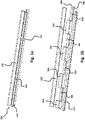
- FIG. 1a illustrates a cutting member according to the present disclosure.
- Fig. 1b shows an exploded view of the cutting member of Fig. 1a .
- a cutting member 10a comprises a base portion 14a configured to couple the cutting member 10a to a razor cartridge being formed of a single sheet of material.
- the base portion can be formed of a single sheet of material as shown in Fig. 1a . In other examples (as discussed in more detail below), the base portion can be formed of multiple fixedly connected sheets of material.
- the base portion 14a defines two opposing broad surfaces (only one broad surface 11a is visible in Fig. la) connected by edges of the base portion 14a.
- the base portion can have an upper edge and an opposing lower edge delimiting the broad surfaces.
- the base portion can have two opposing lateral edges delimiting the broad surfaces.
- the edge can be "virtual", i.e., another element can directly abut the edge.
- the base portion can have a longitudinal extension (i.e., in parallel to a cutting edge) which is more than 5 times larger than a vertical extension (i.e., orthogonal to the longitudinal direction from an attachment area of cutting edge portions to an edge opposite to the attachment area of cutting edge portions).
- the longitudinal extension and the vertical extension define the broad surfaces of the base portion.
- a longitudinal extension of the base portion can be more than 2 cm.
- a vertical extension of the base portion can be between about 2 mm and 8 mm (e.g., between 2 mm and 8 mm).
- a thickness of the base portion i.e., an extension orthogonal to the longitudinal direction and the vertical direction
- the thickness of the base portion can refer to a distance between the broad surfaces defined by the base portion and define a smaller extension of the edges (the larger extension being the longitudinal and vertical extensions, respectively). In addition or alternatively, a thickness can be less than about 1 mm (e.g., less than 1mm). In one example, the base portion has a longitudinal extension of more than 2 cm, a vertical extension of from 2 mm to 6 mm and a thickness of less than 1 mm. The base portion can be curved in some examples.
- the cutting member 10a further comprises a first cutting edge portion 12a connected to one edge of the base portion 14a and extending at an angle in a first direction (i.e., substantially towards the viewer in Fig. la).
- the one edge can be an edge extending along the longitudinal extension of the base portion 14a (i.e., an upper edge if the base portion is oriented so that the broad surfaces extend in vertical planes).
- the cutting member also comprises a second cutting edge portion 12b connected to the one edge the base portion 14a and extending at an angle in second first direction (i.e., substantially away from the viewer in Fig. la). That is, the first and second cutting edge portion 12a are connected to the same edge of the base portion 14a.
- a cutting edge portion refers to a portion including a cutting edge (i.e., a sharpened tip of the cutting edge portion) but can also extend beyond the cutting edge proper.
- a cutting edge portion can be formed of a single piece of material or of multiple pieces of material (which can be fixedly connected, e.g., by welding).
- the first direction and the second direction can have at least an anti-parallel component.
- the first and second directions point in different directions.
- the direction of extension of the cutting edge portions in general relates to a direction pointing from an attachment area of the cutting edge portion towards the cutting edge (i.e., a sharpened tip of the cutting edge portion) of the cutting edge portion.
- the directions of extension for the cutting edge portions 12a, 2b are indicated by broken arrows in Fig. 2 . These directions have an anti-parallel component as long as they are not parallel. In some examples the directions are strictly anti-parallel. In some examples, the first direction and the second direction inscribe an angle of between about 180° (e.g., 180°, i.e., the directions are anti-parallel) and about 60° (e.g., 60°). In other words, the first cutting edge portion 12a and the second cutting edge portion 12b can extend on different sides of a plane including the base portion 14a (basically including the broad surfaces of the base portion).
- the base portion 14a can form a common support for both the first cutting edge portion 12a and the second cutting edge portion 12b.
- the cutting member 10a includes a blade support comprising the base portion 14a, a first blade mounting portion and a second blade mounting portion.
- the first cutting edge portion 12a is attached to the first blade mounting portion and the second cutting edge portion 12b is attached to the second blade mounting portion (i.e., the blade mounting portions indirectly connect the cutting edge portion to an edge of the base portion).
- the first blade mounting portion can extend form the base portion 14a (an edge of the base portion) in the first direction.
- the second blade mounting portion can extend form the base portion 14a (the edge of the base portion) in the second direction.
- each blade mounting portion can comprise one or more protruding tabs 15a-d and 16a-d extending in the same direction from the base portion 14a (an edge of the base portion) of the cutting member 10a for receiving a respective cutting edge portion 12a, 12b.
- the first blade mounting portion includes a first set of one or more protruding tabs 15a-d and the second blade mounting portion includes a second set of one or more protruding tabs 16a-d.
- the protruding tabs 15a-d, 16a-d of the blade mounting portions of a cutting member 10a can be arranged in an alternating manner along a longitudinal extension of the base portion 14a.
- areas where a protruding tab of the first set of one or more protruding tabs 15a-d extends from the base portion 14a follow areas where a protruding tab of the second set of one or more protruding tabs 15a-d extends from the base portion 14a.
- the first and/or the second blade mounting portion includes only one tab.
- the first and/or the second blade mounting portion comprises two or more protruding tabs extending in the same direction from the base portion (e.g., both the first and the second blade mounting portion comprises two or more protruding tabs extending in the same direction from the base portion).
- the tabs can also be differently shaped than the tabs of Fig. 1b , as long as they are suitable toe support a cutting edge portion.
- the blade support comprising the base portion 14a, the first blade mounting portion and the second blade mounting portion can be formed from a single piece of material (e.g., a sheet of metal).
- the first blade mounting portion and the second blade mounting portion are formed by dicing or cutting and bending a sheet of material (e.g., a sheet of metal) in different directions (e.g., to from the protruding tabs 15a-d and 16a-d).
- the cutting edge portions 12a, 12b can be attached to the first and second blade mounting portions (e.g., the protruding tabs 15a-d and 16a-d) by any suitable technique.
- the first and second cutting edge portions 12a, 12b are welded to the respective blade mounting portions.
- the first and second cutting edge portions 12a, 12b are attached to the respective blade mounting portions by an adhesive or by soldering.
- each blade mounting portion has an outer surface (visible in Fig. 1b ) which is oriented towards a shaving plane when in use (i.e., which would be visible when looking at a razor cartridge including the cutting members when the respective cutting edge portions where removed). This outer surface can carry the respective cutting edge portion.
- first cutting edge portion and/or the second cutting edge portion is attached to a respective inner surface of the respective blade mounting portion that, in use, faces away from the shaving plane.
- each blade mounting portion has an inner surface (not visible in Fig. 1b ) which is oriented away from a shaving plane when in use (i.e., which would not visible when looking at a razor cartridge including the cutting members when the respective cutting edge portions where removed). This inner surface can carry the respective cutting edge portion.
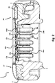
- Fig. 2 shows a cross-section of a razor cartridge 1 according to the present disclosure.
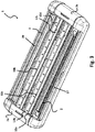
- Fig. 3 shows a perspective view of the razor cartridge of Fig. 2 .
- the razor cartridge 1 includes a razor cartridge housing 5 and one or more cutting members 10a, 10b as described in the present disclosure arranged between a first longitudinal side 17 and a second longitudinal side 20 of the razor cartridge housing.
- the first cutting edge portion 12a, 12c of each of the cutting members 10a, 10b is oriented towards the first longitudinal side 17 and the second cutting edge portion 12b, 12d of each of the cutting members 10a, 10b is oriented towards the second longitudinal side 20.
- the expression "is oriented towards” does not require that the cutting edge portions directly point towards the respective longitudinal side of the razor cartridge (but also include point to an area above or below the respective longitudinal side of the razor cartridge).
- the razor cartridge 1 includes two cutting members 10a, 10b.
- a razor cartridge can only include a single cutting member as described in the present disclosure.
- a razor cartridge can include two or more cutting members as described in the present disclosure (e.g., three cutting members or four cutting members).
- a razor cartridge includes only cutting members as described in the present disclosure (e.g., excluding one or more trimer blades).
- the razor cartridge also includes cutting members not configured as described in the present disclosure (e.g., "conventional" cutting members having a single cutting edge).
- the razor cartridge includes a skin guard 2 arranged at the first longitudinal side 17 and a cap element 3 (e.g., including a lubricating strip 31 or other skin care element) arranged at the second longitudinal side 20.
- This arrangement corresponds to a razor cartridge which is designed to be moved so that the first longitudinal side 17 comes into contact with an area of skin to be treated first (i.e., a shaving direction points towards the left side in Fig. 2 ).
- the razor cartridges including the cutting members of the present disclosure can be operated in two shaving directions in some examples. When moving the razor cartridge in a first shaving direction, the first cutting edge portions 12a, 12c of each of the cutting members 10a, 10b of the razor cartridge can shave an area to be treated.
- the second cutting edge portions 12b, 12d of each of the cutting members 10a, 10b of the razor cartridge can shave an area to be treated.
- the respective cutting edge portions not taking part in the shaving operation or the outer surfaces of the respective blade mounting portions if the cutting edge portions are attached to an inner surface as described below
- the cutting members of the present disclosure can allow for multiple shaving directions and improve the shaving performance in some examples.
- a razor cartridge can also be arranged differently.
- other elements than a skin guard 2 and a cap 3 can be arranged at the first and second longitudinal sides 17, 20 of the razor cartridge 1.
- both the first and second longitudinal sides 17, 20 could include a skin guard (e.g., to prepare the skin to be treated for the imminent shaving operation, e.g., by erecting the hair) and/or a cap element configured to treat the skin after a shaving operation.
- the razor cartridge does not have a preferred shaving direction (but is configured substantially symmetrical with respect to the skin contacting elements).
- the base portions 14a, 14b of the cutting members 10a, 10b are movably arranged within the razor cartridge housing 5 in a direction orthogonal to a shaving plane SH defined by a skin-contacting side of the razor cartridge housing (i.e., the base portions 14a, 14b can move in a vertical direction as described above).
- the razor cartridge provides respective seat portions 6a, 6b for attaching the base portions 14a, 14b.
- the seat portions 6a, 6b can include elastic elements (e.g., leaf springs - not shown in Fig. 2 ) to allow the movement of the cutting members 10a, 10b.
- the base portions 14a, 14b of the cutting members 10a, 10b are rigidly connected to the razor cartridge housing 5 (i.e., the base portions 14a, 14b cannot move relative to the razor cartridge housing 5).
- Fig. 4a and Fig. 4b illustrate further examples of the cutting edge members 10c, 10e of the present disclosure.
- the cutting member 10c comprises a first blade support and a second blade support, each blade support comprising a body portion 141a, 141b and a blade mounting portion 19a, 19b.
- a first cutting edge portion 12e is attached to the blade mounting portion of the first blade support and a second cutting edge 12f portion is attached to the blade mounting portion of the second blade support.
- the body portions of the first and the second blade supports are attached to one another such that the first cutting edge portion and the second cutting edge portion are oriented away from one another.
- the attached body portions 141a, 141b form a base portion 14c of the cutting member 10c as described herein having two broad surfaces connected by edges.
- the first and second cutting edge portions 12e, 12f are (indirectly) connected to an edge of the base portion 14c (by the blade mounting portion 19a, 19b).
- the base portion 14c of the cutting member 10c is formed of two sheets of material which are fixedly attached.
- the base portion 14c can have the extensions discussed above in connection with Fig. 1a (i.e., the fixedly attached sheets can be equated with the single sheet of Fig. la).
- the (multi-partite) base portion 14c forms a common support for the two cutting edge portions 12e, 12f.
- the first blade support includes the first body portion 141a and the first blade mounting portion 19a for attaching the first cutting edge portion 12e.
- the second blade support includes the second body portion 141b and the second blade mounting portion 19b for attaching the second cutting edge portion 12f.
- the cutting member 10c includes a base portion 14c formed of multiple elements (sheets of material), the base portion 14c can still be considered to be a single support (and, e.g., attached to a razor cartridge in a single seat).
- the first blade support and the second blade support of Fig. 4b can be identical.
- two identical blade supports can be attached in a back-to-back manner. This can simplify production in some examples as no special blade supports might be required for a cutting member including two cutting edges according to the present disclosure (and the blade supports of "conventional" cutting members can be used in some examples, or at least with only minor modifications).
- the blade supports can be attached to form the base portion 14c by any suitable technique.
- the blade supports are combined by welding.
- the blade supports are combined by an adhesive or by soldering.
- additional elements can be arranged between the blade supports in a fixedly connected manner.
- the blade mounting portions 19a, 19b of the cutting member of Fig. 4b can each be a single planar element extending along the longitudinal extension of the base portion 14c (and being directly connected to an edge of the base portion 14c).
- the cutting edge portions 12e, 12f are attached to outer surfaces of the blade mounting portions 19a, 19b which in use, face towards the shaving plane.
- the cutting edge portions can be attached to inner surfaces of the blade mounting portions which in use, face away from the shaving plane (in this respect, the teachings discussed above in connection with Fig. 1a are also applicable to the cutting member of Fig. 4b ).
- Fig. 4a shows a further example of a cutting member 10e comprising a first bent blade 18a and a second bent blade 18b.
- Each bent blade 18a, 18b comprises a body portion 141c, 141d and a cutting edge portion 12g, 12h.
- the body portions 141c, 141d of the first and the second bent blades 18a, 18b are attached to one another to form the base portion 14e of the cutting member 10e having two broad surfaces connected by edges.
- the first and second cutting edge portions 12g, 12h are (directly) connected to an edge of the base portion 14e.
- the cutting edge portion 12g of the first bent blade 18a and the cutting edge portion 12h of the second bent blade 18a are oriented away from each other.
- each bent blade 18a, 18b can include one cutting edge portion 12g, 12h of the cutting member 10e and a part of the base portion 14a in an integral manner.
- the bent blades 18a, 18b can be bent from a single sheet of material (e.g., a sheet of metal).
- the base portion 14e of the cutting member 10e is formed of two sheets of material which are fixedly attached.
- the base portion 14e can have the extensions discussed above in connection with Fig. 1a (i.e., the fixedly attached sheets can be equated with the single sheet of Fig. la).
- the (multi-partite) base portion 14e forms a common support for the two cutting edge portions 12g, 12h, which, however, extends as an integral part from the body portions 141c, 141d.
- the blade supports can be attached to form the base portion 14c by any suitable technique.
- the blade supports are combined by welding.
- the blade supports are combined by an adhesive or by soldering.
- additional elements can be arranged between the blade supports in a fixedly connected manner.
- a cutting member can include one bent blade as shown in Fig. 4a and one multipartite blade as shown in Fig. 4b which are fixedly attached to each other.
- Fig. 5 shows a cross-section of another razor cartridge 1a according to the present disclosure.
- the razor cartridge 1a of Fig. 5 shares several features with the razor cartridge 1 of Figs. 2 and 3 .
- the corresponding features/elements have the same reference numerals as in Figs. 2 and 3 .
- the aspects and variants of these features/elements described above can equally be applied in the razor cartridge 1a of Fig. 5 .
- the razor cartridge 1a of Fig. 5 includes two cutting members 10c, 10d as described in connection with Fig. 4a above.
- the two cutting members 10c, 10d are arranged between a first longitudinal side 17 and a second longitudinal side 20 of a razor cartridge housing 5.
- the first cutting edge portion 12e, 12g of each of the cutting members 10c, 10d is oriented towards the first longitudinal side 17 and the second cutting edge portion 12f, 12g of each of the cutting members 10c, 10d is oriented towards the second longitudinal side 20.
- the expression "is oriented towards” does not require that the cutting edge portions directly point towards the respective longitudinal side of the razor cartridge (but also include point to an area above or below the respective longitudinal side of the razor cartridge).
- the razor cartridge 1a includes two cutting members 10c, 10d.
- a razor cartridge can only include a single cutting member as described in connection with Fig. 4a .
- a razor cartridge can include two or more cutting members as described in in connection with Fig. 4a (e.g., three cutting members or four cutting members).
- a razor cartridge includes only cutting members as described in in connection with Fig. 4a (e.g., excluding one or more trimmer blades).
- the razor cartridge also includes cutting members not configured as described in connection with Fig. 4a (e.g., "conventional" cutting members having a single cutting edge).
- a razor cartridge can include two or more different types of cutting members as described in the present disclosure (e.g., at least one cutting member as described in connection with Fig. 1a , Fig. 4a and Fig. 4b and at least one cutting member as described in a different one of Fig. 1a , Fig. 4a and Fig. 4b ).
- the cutting member of the present disclosure has a Y-shaped form (see, e.g., Fig. 1a , Fig. 4a and Fig. 4b )
- a stem of the Y can form the base portion of the cutting member of the present disclosure and each branch of the of the Y can form one cutting edge portion of the cutting member of the present disclosure.
- a T-shape is seen as one (extreme) example of a Y-shape according to the present disclosure in which the cutting edge portions extend in antiparallel directions.
- the Y-shaped form can describe a cutting member including multiple components which are fixedly attached (e.g., by welding).
- first cutting edge portion and the base portion define a first internal angle
- second cutting edge and the base portion define a second internal angle.
- An internal angel can be seen as the smaller angle formed by two objects where the first object extends at an angle from the second object.
- An opposite angle of the internal angle is thus the larger angle formed by the formed by two objects where the first object extends at an angle from the second object.
- a value of the first internal angle can range from about 90° (e.g., 90°) to lower than180° and a value of the second internal angle ranges from about 90° (e.g., 90°) to lower than180°.
- the value of the first internal angle can range from about 90° to about 135° (e.g., from 90° to 135°) and the value of the second internal angle can range from about 90° to about 135° (e.g., from 90° to 135°).
- the value of the first internal angle can range from about 105° to about 130° (e.g., from 105° to 130°) and the value of the second internal angle can range from about 105° to about 130° (e.g., from 105° to 13°).
- the values of the first internal angle and the second internal angle can be equal in some examples.
- the values of the first internal angle and the second internal angle cam be different in some examples.
- first cutting edge portion and the second cutting edge portion each comprise a respective cutting edge.
- two or more cutting members of a razor cartridge can be disposed to define inter-blade spans between first cutting edges of the first cutting edge portions, and between second cutting edges of the second cutting edge portions.
- a first dimension D1 of the cutting member corresponds to an orthogonal projection of the length of the first cutting edge portion on the shaving plane and a second dimension D2 of the cutting member corresponds to an orthogonal projection of the length of the second cutting edge portion on the shaving plane.
- the spans at least comprise the longest of D1 or D2 such that the cutting edge portions facing each other do not overlap.
- the first dimension D1 and the second dimension D2 can be equal. In other examples, the first dimension D1 and the second dimension D2 can be different.
- the present disclosure also relates to a shaving razor assembly including a razor handle and a razor cartridge as described in the present disclosure.
- the razor cartridge can be releasably attached to the razor handle, e.g., via a pivotable connection.
- the razor cartridge can be releasably attached to the razor handle via a non-pivotable connection.
- the razor cartridge integrally formed with the razor handle including a pivotable connection.
- the razor cartridge integrally formed with the razor handle including a non-pivotable connection.
- the present disclosure also relates to a kit of parts including a razor handle and a razor cartridge holder comprising a plurality of razor cartridges as described in the present disclosure.
- the present disclosure also relates to a kit of parts including a razor cartridge holder and a plurality of razor cartridges as described in the present disclosure.
- the present disclosure also relates to a method of manufacturing a razor cartridge relates to methods of manufacturing the cutting members and/or the razor cartridges according to the present disclosure (several aspects of the manufacturing methods have been described in the context of the discussion of the cutting members and razor cartridges above).
- the present disclosure also relates to the cutting members, razor cartridges, razors, kits and methods of the following aspects:
Landscapes
- Life Sciences & Earth Sciences (AREA)
- Forests & Forestry (AREA)
- Engineering & Computer Science (AREA)
- Mechanical Engineering (AREA)
- Physics & Mathematics (AREA)
- Geometry (AREA)
- Knives (AREA)
Abstract
Description
- The present disclosure relates to cutting members, razor cartridges, shaving razor assemblies and methods of manufacturing a razor cartridge.
- Safety razors with multiple blades have been known for quite some time. However, there is an ongoing effort to improve the properties of safety razors with multiple blades. In particular, the reduction or prevention of nicks and cuts while at the same time providing a close shave and maintaining a sufficient level of rinsability (e.g., avoidance of hard to remove debris getting stuck in the cartridge between the blades) can be an issue. Some of the above-recited objects might result in conflicting design requirements. For instance, improving rinsability can mean increasing an inter-blade span (i.e., a distance between a first cutting edge and a subsequent cutting edge) to make room for the debris to be rinsed away. Avoiding nicks and cuts, on the other hand, can be reduced by a decreased inter-blade span to reduce the amount of skin bulge forming between two blades. Moreover, safety razors and their cartridges should be produced in a resource efficient manner.
- In a first general aspect, the present disclosure relates to a base portion configured to couple the cutting member to a razor cartridge being formed of a single sheet of material or multiple fixedly connected sheets of material, the base portion defining two opposite broad surfaces and edges connecting the broad surfaces, a first cutting edge portion connected to one edge of the base portion and extending at an angle in a first direction, and a second cutting edge portion connected to the one edge of the base portion and extending at an angle in a second direction different from the first direction.
- In a second general aspect, the present disclosure relates to a razor cartridge including at least one cutting member according to the first general aspect.
- The present disclosure also relates to shaving razors and kits of parts including one or more razor cartridges according to the second general aspect.
- In a third general aspect, the present disclosure relates to method of manufacturing a razor cartridge according to the second general aspect.
- Particular examples of the first to third general aspects can be implemented so as to realize one or more of the following advantages.
- First, the cutting members of the present disclosure can provide for additional skin support to reduce skin bulge and, in turn, nicks and cuts. This can be accomplished by providing a first cutting edge portion extending in a first direction which can be used to shave in some situations and a second cutting edge portion extending in a second direction can support the skin. If the razor is moved in an opposite direction the roles of the first and second cutting edge portions can swap (i.e., the second cutting edge portion is used for shaving and the first cutting edge portion for skin support).
- On the other hand, a room between two cutting edge portions facing each other (in an arrangement with two or more cutting edge members according to the present disclosure) can be large enough to secure a certain degree of rinsability as two cutting edge portions are supported on one (common) base portion. For instance, in a multiblade cartridge with four blades currently for base or support portions are provided which have to be supported in a housing of a cartridge. When using the cutting members of the present disclosure two (common) base or support portions (one for two cutting edge portions) can suffice.
- Second, a shaving efficiency and performance can be improved as the cutting members of the present disclosure can be moved in two opposite directions (shaving directions) while shaving. This can be beneficial as two shaving operations can be performed with a single back and forth motion. It can also improve the shaving result to cover an area of skin in a first direction with a first stroke and an opposite direction with a second stroke (e.g., hair which is pushed down but not cut during the first stroke can be cut during the second stroke).
- Third, the cutting members themselves and the cartridges can be manufactured in a more resource-efficient manner in some examples as only a single (common) base portion is employed for two cutting edge portions. Accordingly, only a single (common) base portion has to be supported with respective support elements of housing of a razor cartridge.
- Certain terms are used in the following manner in the present disclosure:
The expression "connected to" is not limited to a direct connection between two objects (i.e., it is not required that the two objects abut). For instance, a first object and a second object can be indirectly connected through a third object (e.g., a cutting edge portion can be indirectly connected to an edge of the base portion through another component such as a blade mounting portion). - The expression "extending at an angle" relates to an angle which is smaller than 180° (e.g., smaller than 160°). Moreover, the expression "extending at an angle" specifies that the first object extending at an angle and the second object from which the first object extends inscribe the angle (e.g., the base portion extends in a first vertical direction and the cutting edge portions and the base portion define an inscribed angle). The expression "extending at an angle" includes but does not require direct contact between the first object extending at an angle and the second object from which the first object extends.
- A "sheet of material" is an elongated piece of material having an extension in a first direction (e.g., a thickness) which is (substantially) smaller (e.g., at least 10 times smaller or at least 50 times smaller) than each of the extensions in a second and third direction (all directions being mutually orthogonal). Thus, a "sheet of material" forms a first broad surface and a second, opposite broad surface. The term "sheet of material" relates to the geometry and not to a class of material (e.g., a "sheet of material" can include or consist of a metal or alloy or a plastic material). The term "sheet of material" can relate to a substantially planar form factor (having a thickness that is at least 10 times smaller or at least 50 times smaller than a length and a width). However, a "sheet of material" does not have to be perfectly flat and/or planar. In some examples, a sheet of material can include features such as protrusions, slots or holes in the broad surfaces of the sheet of material and/or at the edges.
- The term "edge" refers to a boundary limiting an object (e.g., the base portion). This does not necessarily mean that there is a material boundary. For instance, the base portion can be directly connected to blade mounting portion (e.g., these elements can be formed from the same sheet of material) but nevertheless there can be an edge limiting the base portion.
- The term "fixedly attached" relates to a permanent or non-detachable attachment. For instance, a weld connection or an adhesive can be used to fixedly attach two objects. Two objects connected by a screw connection or a clip connection or by friction/releasable pressing forces, on the other hand, are not "fixedly attached".
-
-
Fig. 1a illustrates a cutting member according to the present disclosure. -
Fig. 1b shows an exploded view of the cutting member of Fig. la. -
Fig. 2 shows a cross-section of a razor cartridge according to the present disclosure. -
Fig. 3 shows a perspective view of the razor cartridge ofFig. 2 . -
Fig. 4a and Fig. 4b illustrate further examples of the cutting edge members of the present disclosure. -
Fig. 5 shows a cross-section of another razor cartridge according to the present disclosure. -
Fig. 1a illustrates a cutting member according to the present disclosure.Fig. 1b shows an exploded view of the cutting member ofFig. 1a . - As shown in
Fig. 1a , acutting member 10a comprises abase portion 14a configured to couple thecutting member 10a to a razor cartridge being formed of a single sheet of material. - The base portion can be formed of a single sheet of material as shown in
Fig. 1a . In other examples (as discussed in more detail below), the base portion can be formed of multiple fixedly connected sheets of material. - The
base portion 14a defines two opposing broad surfaces (only onebroad surface 11a is visible in Fig. la) connected by edges of thebase portion 14a. In general, the base portion can have an upper edge and an opposing lower edge delimiting the broad surfaces. Accordingly, the base portion can have two opposing lateral edges delimiting the broad surfaces. As discussed above, the edge can be "virtual", i.e., another element can directly abut the edge. - In general, the base portion can have a longitudinal extension (i.e., in parallel to a cutting edge) which is more than 5 times larger than a vertical extension (i.e., orthogonal to the longitudinal direction from an attachment area of cutting edge portions to an edge opposite to the attachment area of cutting edge portions). The longitudinal extension and the vertical extension define the broad surfaces of the base portion. In some examples, a longitudinal extension of the base portion can be more than 2 cm. In addition or alternatively, a vertical extension of the base portion can be between about 2 mm and 8 mm (e.g., between 2 mm and 8 mm). A thickness of the base portion (i.e., an extension orthogonal to the longitudinal direction and the vertical direction) can be at least 5 times smaller than the vertical extension. The thickness of the base portion can refer to a distance between the broad surfaces defined by the base portion and define a smaller extension of the edges (the larger extension being the longitudinal and vertical extensions, respectively). In addition or alternatively, a thickness can be less than about 1 mm (e.g., less than 1mm). In one example, the base portion has a longitudinal extension of more than 2 cm, a vertical extension of from 2 mm to 6 mm and a thickness of less than 1 mm. The base portion can be curved in some examples.
- The cutting
member 10a further comprises a firstcutting edge portion 12a connected to one edge of thebase portion 14a and extending at an angle in a first direction (i.e., substantially towards the viewer in Fig. la). The one edge can be an edge extending along the longitudinal extension of thebase portion 14a (i.e., an upper edge if the base portion is oriented so that the broad surfaces extend in vertical planes). The cutting member also comprises a secondcutting edge portion 12b connected to the one edge thebase portion 14a and extending at an angle in second first direction (i.e., substantially away from the viewer in Fig. la). That is, the first and secondcutting edge portion 12a are connected to the same edge of thebase portion 14a. In general, a cutting edge portion refers to a portion including a cutting edge (i.e., a sharpened tip of the cutting edge portion) but can also extend beyond the cutting edge proper. A cutting edge portion can be formed of a single piece of material or of multiple pieces of material (which can be fixedly connected, e.g., by welding). - The first direction and the second direction can have at least an anti-parallel component. In other words, the first and second directions point in different directions.
- The direction of extension of the cutting edge portions in general relates to a direction pointing from an attachment area of the cutting edge portion towards the cutting edge (i.e., a sharpened tip of the cutting edge portion) of the cutting edge portion. The directions of extension for the
cutting edge portions 12a, 2b are indicated by broken arrows inFig. 2 . These directions have an anti-parallel component as long as they are not parallel. In some examples the directions are strictly anti-parallel. In some examples, the first direction and the second direction inscribe an angle of between about 180° (e.g., 180°, i.e., the directions are anti-parallel) and about 60° (e.g., 60°). In other words, the firstcutting edge portion 12a and the secondcutting edge portion 12b can extend on different sides of a plane including thebase portion 14a (basically including the broad surfaces of the base portion). - The
base portion 14a can form a common support for both the firstcutting edge portion 12a and the secondcutting edge portion 12b. - In the examples of
Fig. 1a , the cuttingmember 10a includes a blade support comprising thebase portion 14a, a first blade mounting portion and a second blade mounting portion. The firstcutting edge portion 12a is attached to the first blade mounting portion and the secondcutting edge portion 12b is attached to the second blade mounting portion (i.e., the blade mounting portions indirectly connect the cutting edge portion to an edge of the base portion). The first blade mounting portion can extend form thebase portion 14a (an edge of the base portion) in the first direction. The second blade mounting portion can extend form thebase portion 14a (the edge of the base portion) in the second direction. - As can be seen in
Fig. 1b , each blade mounting portion can comprise one or moreprotruding tabs 15a-d and 16a-d extending in the same direction from thebase portion 14a (an edge of the base portion) of the cuttingmember 10a for receiving a respectivecutting edge portion protruding tabs 15a-d and the second blade mounting portion includes a second set of one or moreprotruding tabs 16a-d. - The protruding
tabs 15a-d, 16a-d of the blade mounting portions of a cuttingmember 10a can be arranged in an alternating manner along a longitudinal extension of thebase portion 14a. In the other words, when moving along the longitudinal extension of thebase portion 14a, areas where a protruding tab of the first set of one or moreprotruding tabs 15a-d extends from thebase portion 14a follow areas where a protruding tab of the second set of one or moreprotruding tabs 15a-d extends from thebase portion 14a. - In the example of
Fig. 1b , there are four protrudingtabs 15a-d and 16a-d forming each the first and second blade mounting portion. However, in other examples there can be a different number of protruding tabs. In some examples, the first and/or the second blade mounting portion includes only one tab. In other examples (or additionally), the first and/or the second blade mounting portion comprises two or more protruding tabs extending in the same direction from the base portion (e.g., both the first and the second blade mounting portion comprises two or more protruding tabs extending in the same direction from the base portion). The tabs can also be differently shaped than the tabs ofFig. 1b , as long as they are suitable toe support a cutting edge portion. - The blade support comprising the
base portion 14a, the first blade mounting portion and the second blade mounting portion can be formed from a single piece of material (e.g., a sheet of metal). In some examples, the first blade mounting portion and the second blade mounting portion are formed by dicing or cutting and bending a sheet of material (e.g., a sheet of metal) in different directions (e.g., to from the protrudingtabs 15a-d and 16a-d). - The
cutting edge portions tabs 15a-d and 16a-d) by any suitable technique. In some examples, the first and secondcutting edge portions cutting edge portions base portion 14a from a single piece of material can reduce the number of resources required to manufacture a cutting member in some examples. Instead of two separate blade supports each carrying a cutting edge portion a single element can carry two cutting edge portions. This can also reduce the complexity of a cartridge to which the cutting member is attached as only a single blade support must be supported in some examples. - In the example of
Figs. 1a and 1b , the firstcutting edge portion 12a and the secondcutting edge portion 12a are attached to a respective outer surface of the respective blade mounting portion that, in use, faces the shaving plane. In other words, each blade mounting portion has an outer surface (visible inFig. 1b ) which is oriented towards a shaving plane when in use (i.e., which would be visible when looking at a razor cartridge including the cutting members when the respective cutting edge portions where removed). This outer surface can carry the respective cutting edge portion. - In other examples, the first cutting edge portion and/or the second cutting edge portion is attached to a respective inner surface of the respective blade mounting portion that, in use, faces away from the shaving plane. In other words, each blade mounting portion has an inner surface (not visible in
Fig. 1b ) which is oriented away from a shaving plane when in use (i.e., which would not visible when looking at a razor cartridge including the cutting members when the respective cutting edge portions where removed). This inner surface can carry the respective cutting edge portion. -
Fig. 2 shows a cross-section of arazor cartridge 1 according to the present disclosure.Fig. 3 shows a perspective view of the razor cartridge ofFig. 2 . - In some examples, the
razor cartridge 1 includes arazor cartridge housing 5 and one ormore cutting members longitudinal side 17 and a secondlongitudinal side 20 of the razor cartridge housing. The firstcutting edge portion members longitudinal side 17 and the secondcutting edge portion members longitudinal side 20. As can be seen inFig. 2 , the expression "is oriented towards" does not require that the cutting edge portions directly point towards the respective longitudinal side of the razor cartridge (but also include point to an area above or below the respective longitudinal side of the razor cartridge). - In the example of
Fig. 2 , therazor cartridge 1 includes two cuttingmembers - In the example of
Fig. 2 , the razor cartridge includes askin guard 2 arranged at the firstlongitudinal side 17 and a cap element 3 (e.g., including alubricating strip 31 or other skin care element) arranged at the secondlongitudinal side 20. This arrangement corresponds to a razor cartridge which is designed to be moved so that the firstlongitudinal side 17 comes into contact with an area of skin to be treated first (i.e., a shaving direction points towards the left side inFig. 2 ). The razor cartridges including the cutting members of the present disclosure can be operated in two shaving directions in some examples. When moving the razor cartridge in a first shaving direction, the firstcutting edge portions members cutting edge portions members - Returning to
Fig. 2 , a razor cartridge can also be arranged differently. For instance, in view of two possible shaving directions other elements than askin guard 2 and acap 3 can be arranged at the first and secondlongitudinal sides razor cartridge 1. For example, both the first and secondlongitudinal sides - In the example of
Fig. 2 , thebase portions members razor cartridge housing 5 in a direction orthogonal to a shaving plane SH defined by a skin-contacting side of the razor cartridge housing (i.e., thebase portions respective seat portions base portions seat portions Fig. 2 ) to allow the movement of the cuttingmembers - In other examples, the
base portions members base portions -
Fig. 4a and Fig. 4b illustrate further examples of thecutting edge members - In some examples, as shown in
Fig. 4b , the cuttingmember 10c comprises a first blade support and a second blade support, each blade support comprising abody portion blade mounting portion cutting edge portion 12e is attached to the blade mounting portion of the first blade support and asecond cutting edge 12f portion is attached to the blade mounting portion of the second blade support. The body portions of the first and the second blade supports are attached to one another such that the first cutting edge portion and the second cutting edge portion are oriented away from one another. The attachedbody portions base portion 14c of the cuttingmember 10c as described herein having two broad surfaces connected by edges. The first and secondcutting edge portions base portion 14c (by theblade mounting portion base portion 14c of the cuttingmember 10c is formed of two sheets of material which are fixedly attached. Thebase portion 14c can have the extensions discussed above in connection withFig. 1a (i.e., the fixedly attached sheets can be equated with the single sheet of Fig. la). As can be seen, the (multi-partite)base portion 14c forms a common support for the twocutting edge portions - In detail, the first blade support includes the
first body portion 141a and the firstblade mounting portion 19a for attaching the firstcutting edge portion 12e. The second blade support includes thesecond body portion 141b and the secondblade mounting portion 19b for attaching the secondcutting edge portion 12f. - Even though the cutting
member 10c includes abase portion 14c formed of multiple elements (sheets of material), thebase portion 14c can still be considered to be a single support (and, e.g., attached to a razor cartridge in a single seat). Moreover, the first blade support and the second blade support ofFig. 4b can be identical. For instance, two identical blade supports can be attached in a back-to-back manner. This can simplify production in some examples as no special blade supports might be required for a cutting member including two cutting edges according to the present disclosure (and the blade supports of "conventional" cutting members can be used in some examples, or at least with only minor modifications). - The blade supports can be attached to form the
base portion 14c by any suitable technique. In some examples, the blade supports are combined by welding. In other examples, the blade supports are combined by an adhesive or by soldering. In some examples, additional elements can be arranged between the blade supports in a fixedly connected manner. - The
blade mounting portions Fig. 4b can each be a single planar element extending along the longitudinal extension of thebase portion 14c (and being directly connected to an edge of thebase portion 14c). In the example ofFig. 4b , thecutting edge portions blade mounting portions Fig. 1a are also applicable to the cutting member ofFig. 4b ). -
Fig. 4a shows a further example of a cuttingmember 10e comprising a firstbent blade 18a and a secondbent blade 18b. Eachbent blade body portion cutting edge portion body portions bent blades base portion 14e of the cuttingmember 10e having two broad surfaces connected by edges. The first and secondcutting edge portions base portion 14e. Thecutting edge portion 12g of the firstbent blade 18a and thecutting edge portion 12h of the secondbent blade 18a are oriented away from each other. In the example ofFig. 4a eachbent blade cutting edge portion member 10e and a part of thebase portion 14a in an integral manner. For instance, thebent blades Fig. 4b , thebase portion 14e of the cuttingmember 10e is formed of two sheets of material which are fixedly attached. Thebase portion 14e can have the extensions discussed above in connection withFig. 1a (i.e., the fixedly attached sheets can be equated with the single sheet of Fig. la). As can be seen, the (multi-partite)base portion 14e forms a common support for the twocutting edge portions body portions - The blade supports can be attached to form the
base portion 14c by any suitable technique. In some examples, the blade supports are combined by welding. In other examples, the blade supports are combined by an adhesive or by soldering. In some examples, additional elements can be arranged between the blade supports in a fixedly connected manner. - In some examples, a cutting member can include one bent blade as shown in
Fig. 4a and one multipartite blade as shown inFig. 4b which are fixedly attached to each other. -
Fig. 5 shows a cross-section of another razor cartridge 1a according to the present disclosure. The razor cartridge 1a ofFig. 5 shares several features with therazor cartridge 1 ofFigs. 2 and3 . The corresponding features/elements have the same reference numerals as inFigs. 2 and3 . The aspects and variants of these features/elements described above can equally be applied in the razor cartridge 1a ofFig. 5 . - As can be seen, the razor cartridge 1a of
Fig. 5 includes two cuttingmembers Fig. 4a above. The twocutting members longitudinal side 17 and a secondlongitudinal side 20 of arazor cartridge housing 5. The firstcutting edge portion members longitudinal side 17 and the secondcutting edge portion members longitudinal side 20. As can be seen inFig. 5 , the expression "is oriented towards" does not require that the cutting edge portions directly point towards the respective longitudinal side of the razor cartridge (but also include point to an area above or below the respective longitudinal side of the razor cartridge). - In the example of
Fig. 5 , the razor cartridge 1a includes two cuttingmembers Fig. 4a . In still other examples, a razor cartridge can include two or more cutting members as described in in connection withFig. 4a (e.g., three cutting members or four cutting members). In some examples, a razor cartridge includes only cutting members as described in in connection withFig. 4a (e.g., excluding one or more trimmer blades). In other examples, the razor cartridge also includes cutting members not configured as described in connection withFig. 4a (e.g., "conventional" cutting members having a single cutting edge). In some examples, a razor cartridge can include two or more different types of cutting members as described in the present disclosure (e.g., at least one cutting member as described in connection withFig. 1a ,Fig. 4a and Fig. 4b and at least one cutting member as described in a different one ofFig. 1a ,Fig. 4a and Fig. 4b ). - In the following sections we will describe several further aspects the cutting members and razor cartridges of the present disclosure of some examples.
- In some examples, the cutting member of the present disclosure has a Y-shaped form (see, e.g.,
Fig. 1a ,Fig. 4a and Fig. 4b ) A stem of the Y can form the base portion of the cutting member of the present disclosure and each branch of the of the Y can form one cutting edge portion of the cutting member of the present disclosure. A T-shape is seen as one (extreme) example of a Y-shape according to the present disclosure in which the cutting edge portions extend in antiparallel directions. As can be seen, the Y-shaped form can describe a cutting member including multiple components which are fixedly attached (e.g., by welding). - In some examples, the first cutting edge portion and the base portion define a first internal angle, and the second cutting edge and the base portion define a second internal angle. An internal angel can be seen as the smaller angle formed by two objects where the first object extends at an angle from the second object. An opposite angle of the internal angle is thus the larger angle formed by the formed by two objects where the first object extends at an angle from the second object.
- In some examples, a value of the first internal angle can range from about 90° (e.g., 90°) to lower than180° and a value of the second internal angle ranges from about 90° (e.g., 90°) to lower than180°. For instance, the value of the first internal angle can range from about 90° to about 135° (e.g., from 90° to 135°) and the value of the second internal angle can range from about 90° to about 135° (e.g., from 90° to 135°). In still other examples, the value of the first internal angle can range from about 105° to about 130° (e.g., from 105° to 130°) and the value of the second internal angle can range from about 105° to about 130° (e.g., from 105° to 13°). The values of the first internal angle and the second internal angle can be equal in some examples. The values of the first internal angle and the second internal angle cam be different in some examples.
- As discussed above, the first cutting edge portion and the second cutting edge portion each comprise a respective cutting edge. In some examples, two or more cutting members of a razor cartridge can be disposed to define inter-blade spans between first cutting edges of the first cutting edge portions, and between second cutting edges of the second cutting edge portions. A first dimension D1 of the cutting member corresponds to an orthogonal projection of the length of the first cutting edge portion on the shaving plane and a second dimension D2 of the cutting member corresponds to an orthogonal projection of the length of the second cutting edge portion on the shaving plane. The spans at least comprise the longest of D1 or D2 such that the cutting edge portions facing each other do not overlap. In some examples, the first dimension D1 and the second dimension D2 can be equal. In other examples, the first dimension D1 and the second dimension D2 can be different.
- The present disclosure also relates to a shaving razor assembly including a razor handle and a razor cartridge as described in the present disclosure. The razor cartridge can be releasably attached to the razor handle, e.g., via a pivotable connection. In other examples, the razor cartridge can be releasably attached to the razor handle via a non-pivotable connection. Ins still other examples, the razor cartridge integrally formed with the razor handle including a pivotable connection. In still other examples, the razor cartridge integrally formed with the razor handle including a non-pivotable connection.
- The present disclosure also relates to a kit of parts including a razor handle and a razor cartridge holder comprising a plurality of razor cartridges as described in the present disclosure.
- The present disclosure also relates to a kit of parts including a razor cartridge holder and a plurality of razor cartridges as described in the present disclosure.
- The present disclosure also relates to a method of manufacturing a razor cartridge relates to methods of manufacturing the cutting members and/or the razor cartridges according to the present disclosure (several aspects of the manufacturing methods have been described in the context of the discussion of the cutting members and razor cartridges above).
- The present disclosure also relates to the cutting members, razor cartridges, razors, kits and methods of the following aspects:
- 1. A cutting member comprising:
- a base portion configured to couple the cutting member to a razor cartridge being formed of a single sheet of material or multiple fixedly connected sheets of material, the base portion defining two broad surfaces and edges connecting the two broad surfaces,
- a first cutting edge portion connected to an edge of the base portion and extending at an angle in a first direction, and
- a second cutting edge portion connected to the edge of the base portion and extending at an angle in a second direction different from the first direction.
- 2. A razor cartridge comprising,
a razor cartridge housing, and
one or more cutting members according toaspect 1 arranged between a first longitudinal side and a second longitudinal side of the razor cartridge housing,
wherein the first cutting edge portion of each of the cutting members is oriented towards the first longitudinal side and the second cutting edge portion of each of the cutting members is oriented towards the second longitudinal side. - 3. The razor cartridge of
aspect 2, wherein the base portion of the cutting member is movably arranged within the razor cartridge housing in a direction orthogonal to a shaving plane SH defined by a skin-contacting side of the razor cartridge housing. - 4. The razor cartridge according to
aspect 2 oraspect 3, wherein each cutting member comprises:- a blade support comprising the base portion, a first blade mounting portion and a second blade mounting portion;
- wherein the first cutting edge portion is attached to the first blade mounting portion and wherein the second cutting edge portion is attached to the second blade mounting portion.
- 5. The razor cartridge according to
aspect 2 oraspect 3, wherein each cutting member comprises
a first blade support and a second blade support, each blade support comprising a body portion and a blade mounting portion;
wherein the first cutting edge portion is attached to the blade mounting portion of the first blade support and the second cutting edge portion is attached to the blade mounting portion of the second blade support;
wherein the body portions of the first and the second blade supports are attached to one another such that the first cutting edge portion and the second cutting edge portion are oriented away from one another; and
wherein the attached body portions of the first blade support form the base portion of the cutting member. - 6. The razor cartridge according to any one of
aspects 3 to 4, wherein each blade mounting portion comprises one or more protruding tabs extending in the same direction from the base portion of the cutting member for receiving the cutting edge portion, wherein the protruding tabs of the blade mounting portions of a cutting member are arranged in an alternating manner along a longitudinal extension of the base portion. - 7. The razor cartridge of aspect 6, wherein each blade mounting portion comprises two or more protruding tabs extending in the same direction from the base portion.
- 8. The razor cartridge according to any one of
aspects 3 to 6, wherein the first and second cutting edge portions are welded to the respective blade mounting portions. - 9. The razor cartridge according to
aspects 3 to 8, wherein the first cutting edge portion and/or the second cutting edge portion is attached to a respective outer surface of the respective blade mounting portion that, in use, faces the shaving plane. - 10. The razor cartridge according to
aspects 3 to 8, wherein the first cutting edge portion and/or the second cutting edge portion is attached to a respective inner surface of the respective blade mounting portion that, in use, faces away from the shaving plane. - 11. The razor cartridge according to
aspect 2, wherein each cutting member comprises a first bent blade and a second bent blade, each bent blade comprising a body portion and one of the first and second cutting edge portions, wherein the body portions of the first and the second bent blades are attached to one another such that the cutting edge portion of the first bent blade and the cutting edge portion of the second bent blade are oriented away from each other,
wherein the attached body portions of the first bent blade and the second bent blade form the base portion of the cutting member. - 12. The razor cartridge according to any of the
previous aspects 2 to 10, wherein the cutting member has a Y-shaped form, wherein the stem of the Y forms the base portion and each branch of the of the Y forms one cutting edge portion. - 13. The razor cartridge according to any of the previous aspects, wherein the first cutting edge portion and the base portion define a first internal angle and wherein the second cutting edge and the base portion define a second internal angle, wherein the value of the first internal angle ranges from about 90° to lower than 180° and the value of the second internal angle ranges from about 90° to lower than 180°.
- 14. The razor cartridge according to aspect 13, wherein the value of the first internal angle ranges from about 90° to about 135° and the value of the second internal angle ranges from about 90° to about 135°.
- 15. The razor cartridge according to aspect 13, wherein the value of the first internal angle ranges from about 105° to about 130° and the value of the second internal angle ranges from about 105° to about 130°.
- 16. The razor cartridge according to aspects 13 to 15, wherein the values of the first internal angle and the second internal angle are equal.
- 17. The razor cartridge according to aspects 13 to 15, wherein the values of the first internal angle and the second internal angle are different.
- 18. The razor cartridge according to any of the previous aspects, wherein the first cutting edge portion and the second cutting edge portion respectively comprise a cutting edge.
- 19. The razor cartridge according to any of the previous aspects
wherein two or more cutting members are disposed to define inter-blade spans between first cutting edges of the first cutting edge portions, and between second cutting edges of the second cutting edge portions,
wherein a first dimension D1 of the cutting member corresponds to an orthogonal projection of the length of the first cutting edge portion on the shaving plane and a second dimension D2 of the cutting member corresponds to an orthogonal projection of the length of the second cutting edge portion on the shaving plane, and
wherein the spans at least comprise the longest of D1 or D2 such that the cutting edge portions facing each other do not overlap. - 20. The razor cartridge according to aspect 19, wherein the first dimension D1 and the second dimension D2 are equal.
- 21. The razor cartridge according to aspect 19, wherein the first dimension D1 and the second dimension D2 are different.
- 22. The razor cartridge according to any one of the preceding aspects, wherein the first direction and the second direction have at least an anti-parallel component
- 23. A shaving razor assembly
a razor handle; and
a razor cartridge according to any one ofaspects 2 to 22. - 24. The shaving razor assembly of aspect 23, wherein the razor cartridge is releasably attached to the razor handle via a pivotable connection.
- 25. The shaving razor assembly of aspect 23, wherein the razor cartridge is releasably attached to the razor handle via a non-pivotable connection.
- 26. The shaving razor assembly of aspect 23, wherein the razor cartridge integrally formed with the razor handle via a pivotable connection.
- 27. The shaving razor assembly of aspect 23, wherein the razor cartridge integrally formed with the razor handle via a non-pivotable connection.
- 28. A kit of parts comprising:
- a razor handle; and
- a razor cartridge holder comprising a plurality of razor cartridges according to any one of
aspects 2 to 22.
- 29. A method of manufacturing a cutting member or a razor cartridge as defined in any one of
aspects 1 to 22.
Claims (15)
- A cutting member (10a-e) comprising:a base portion (14a-e) configured to couple the cutting member (10a-e) to a razor cartridge (1; 1a) being formed of a single sheet of material or multiple fixedly connected sheets of material, the base portion (14a-e) defining two opposing broad surfaces connected by edges of the base portion (14a-e),a first cutting edge portion (12a-j) connected to one edge of the base portion (14a-e) and extending at an angle in a first direction, anda second cutting edge portion (12a-j) connected to the one edge of the base portion (14a-e) and extending at an angle in a second direction different from the first direction.
- A razor cartridge (1; 1a) comprising
a razor cartridge housing (5), and
one or more cutting members (10a-e) according to claim 1 arranged between a first longitudinal side (17) and a second longitudinal side (20) of the razor cartridge housing (5),
wherein the first cutting edge portion (12a, c, e, i) of each of the cutting members (10a-e) is oriented towards the first longitudinal side (17) and the second cutting edge portion (12b, d, f, j) of each of the cutting members (10a-e) is oriented towards the second longitudinal side (20) - The razor cartridge (1; 1a) of claim 2, wherein the one or more cutting members (10a-e) comprise two or more cutting members (10a-e).
- The razor cartridge of claim 2 or claim 3, wherein the base portion (14a-e) of each cutting member (10a-e) is movably arranged within the razor cartridge housing (5) in a direction orthogonal to a shaving plane SH defined by a skin-contacting side of the razor cartridge housing (5).
- The razor cartridge according to any one of claims 1 to 4, wherein each cutting member (10a-d) comprises:a blade support comprising the base portion (14a-d), a first blade mounting portion (19a) and a second blade mounting portion (19b);wherein the first cutting edge portion (12a, c, e, i) is attached to the first blade mounting portion (19a) and wherein the second cutting edge portion (12b, d, f, j) is attached to the second blade mounting portion (19b).
- The razor cartridge according to any one of claims 2 to 5, wherein each cutting member (10a-d) comprises
a first blade support and a second blade support, each blade support comprising a body portion (141a; 141b) and a blade mounting portion (19a; 19b);
wherein the first cutting edge portion (12a, c, e, i) is attached to the blade mounting portion (19a) of the first blade support and the second cutting edge portion (12b, d, f, j) is attached to the blade mounting portion (19b) of the second blade support;
wherein the body portions (141a; 141b) of the first and the second blade supports are attached to one another such that the first cutting edge portion (12a, c, e, i) and the second cutting edge portion (12b, d, f, j) are oriented away from one another; and
wherein the attached body portions (141a; 141b) of the first blade support form the base portion (14a-d) of the cutting member (10a-d). - The razor cartridge according to any one of claims 5 to 6, wherein each blade mounting portion comprises one or more protruding tabs (15a-d; 16a-d) extending in the same direction from the base portion (14a; 14b) of the cutting member (10a; 10b) for receiving the cutting edge portion (12a-d), wherein the protruding tabs (15a-d; 16a-d) of the blade mounting portions of are arranged in an alternating manner along a longitudinal extension of the base portion (14a; 14b).
- The razor cartridge according to any one of claims 5 to 7, wherein the first and second cutting edge portions (12a-f, i, j) are welded to the respective blade mounting portions (19a; 19b).
- The razor cartridge according to any one of claims 3 to 8, wherein the first cutting edge portion (12a, c, e, i) and/or the second cutting edge portion (12b, d, f, j) is attached to a respective outer surface of the respective blade mounting portion (19a; 19b) that, in use, faces the shaving plane, or
wherein the first cutting edge portion and/or the second cutting edge portion is attached to a respective inner surface of the respective blade mounting portion that, in use, faces away from the shaving plane. - The razor cartridge according to claim 2 or claim 3, wherein each cutting member (10e) comprises a first bent blade (18a) and a second bent blade (18b), each bent blade (18a; 18b) comprising a body portion (141c; 141d) and one of the first and second cutting edge portions (12g; 12h), wherein the body portions (141c; 141d) of the first and the second bent blades (18a; 18b) are attached to one another such that the cutting edge portion (12g) of the first bent blade (18a) and the cutting edge portion (12h) of the second bent blade (18b) are oriented away from each other,
wherein the attached body portions (141c; 141d) of the first bent blade (18a) and the second bent blade (18b) form the base portion (14e) of the cutting member (10e). - The razor cartridge according to any of the previous claims 2 to 10, wherein the cutting member (10a-e) has a Y-shaped form, wherein the stem of the Y forms the base portion (14a-e) and each branch of the of the Y forms one cutting edge portion (12a-j).
- The razor cartridge according to any of the previous claims, wherein the first cutting edge portion and the base portion define a first internal angle and wherein the second cutting edge and the base portion define a second internal angle, wherein the value of the first internal angle ranges from about 90° to lower than 180° and the value of the second internal angle ranges from about 90° to lower than 180°, optionally wherein the value of the first internal angle ranges from about 90° to about 135° and the value of the second internal angle ranges from about 90° to about 135°.
- The razor cartridge according to any of the previous claims, wherein the first cutting edge portion and the second cutting edge portion respectively comprise a cutting edge.
- The razor cartridge according to any of the previous claims,
wherein two or more cutting members (10a-e) are disposed to define inter-blade spans between first cutting edges of the first cutting edge portions, and between second cutting edges of the second cutting edge portions,
wherein a first dimension D1 of the cutting member corresponds to an orthogonal projection of the length of the first cutting edge portion on the shaving plane and a second dimension D2 of the cutting member corresponds to an orthogonal projection of the length of the second cutting edge portion on the shaving plane, and wherein the spans at least comprise the longest of D1 or D2 such that the cutting edge portions facing each other do not overlap. - A shaving razor assembly
a razor handle; and
a razor cartridge (1; 1a) according to any one of claims 2 to 14.
Priority Applications (2)
| Application Number | Priority Date | Filing Date | Title |
|---|---|---|---|
| EP21159362.9A EP4049817B1 (en) | 2021-02-25 | 2021-02-25 | Cutting members with multiple cutting edges |
| US17/652,414 US12420442B2 (en) | 2021-02-25 | 2022-02-24 | Cutting members with multiple cutting edges |
Applications Claiming Priority (1)
| Application Number | Priority Date | Filing Date | Title |
|---|---|---|---|
| EP21159362.9A EP4049817B1 (en) | 2021-02-25 | 2021-02-25 | Cutting members with multiple cutting edges |
Publications (2)
| Publication Number | Publication Date |
|---|---|
| EP4049817A1 true EP4049817A1 (en) | 2022-08-31 |
| EP4049817B1 EP4049817B1 (en) | 2024-05-29 |
Family
ID=74758686
Family Applications (1)
| Application Number | Title | Priority Date | Filing Date |
|---|---|---|---|
| EP21159362.9A Active EP4049817B1 (en) | 2021-02-25 | 2021-02-25 | Cutting members with multiple cutting edges |
Country Status (2)
| Country | Link |
|---|---|
| US (1) | US12420442B2 (en) |
| EP (1) | EP4049817B1 (en) |
Families Citing this family (1)
| Publication number | Priority date | Publication date | Assignee | Title |
|---|---|---|---|---|
| EP4049817B1 (en) * | 2021-02-25 | 2024-05-29 | BIC Violex Single Member S.A. | Cutting members with multiple cutting edges |
Citations (3)
| Publication number | Priority date | Publication date | Assignee | Title |
|---|---|---|---|---|
| US1877149A (en) * | 1931-08-21 | 1932-09-13 | Benjamin M Sylvan | Razor blade |
| DE2544425A1 (en) * | 1974-10-04 | 1976-04-15 | Gillette Co | Safety razor blade and razor head - has double cutting system on both sides with metal or plastic protectors |
| EP3446840A2 (en) * | 2017-08-25 | 2019-02-27 | Ningbo Kaili Holding Group Co., Ltd. | Matrix beard-trimmings guiding razor head |
Family Cites Families (13)
| Publication number | Priority date | Publication date | Assignee | Title |
|---|---|---|---|---|
| DE69433116D1 (en) | 1994-09-06 | 2003-10-09 | Edward A Andrews | BI-DIRECTIONAL SHAVING STRUCTURES AND SYSTEMS |
| KR20060097535A (en) | 2005-03-11 | 2006-09-14 | 홍형표 | 2-way shaver |
| ITTV20080055A1 (en) | 2008-04-11 | 2009-10-12 | Benedetto Mauro De | "INCLINED BLADES SHAPED AND / OR INCLINABLE ON AXIS X AND / OR Z". |
| PL2707180T3 (en) * | 2011-05-13 | 2017-06-30 | Edgewell Personal Care Brands, Llc | Razor blade supports |
| JP5719755B2 (en) * | 2011-11-09 | 2015-05-20 | フェザー安全剃刀株式会社 | Safety razor |
| US20140026424A1 (en) * | 2012-07-24 | 2014-01-30 | The Gillette Company | Razor cartridge |
| USD850721S1 (en) * | 2014-03-05 | 2019-06-04 | Mack-Ray, Inc. | Razor cartridge |
| CN109526214B (en) * | 2016-07-06 | 2021-06-01 | 比克-维尔莱克 | razor system |
| WO2018052802A1 (en) * | 2016-09-14 | 2018-03-22 | Edgewell Personal Care Brands, Llc | Bidirectional shaving device |
| EP3771533B1 (en) * | 2019-07-31 | 2022-09-21 | BIC Violex Single Member S.A. | Razor cartridge |
| CA3160373A1 (en) * | 2019-12-04 | 2021-06-10 | Raymond A. Liberatore | Dual sided razor |
| EP4049817B1 (en) * | 2021-02-25 | 2024-05-29 | BIC Violex Single Member S.A. | Cutting members with multiple cutting edges |
| PL4067025T3 (en) * | 2021-03-31 | 2024-05-06 | BIC Violex Single Member S.A. | Blade elements |
-
2021
- 2021-02-25 EP EP21159362.9A patent/EP4049817B1/en active Active
-
2022
- 2022-02-24 US US17/652,414 patent/US12420442B2/en active Active
Patent Citations (3)
| Publication number | Priority date | Publication date | Assignee | Title |
|---|---|---|---|---|
| US1877149A (en) * | 1931-08-21 | 1932-09-13 | Benjamin M Sylvan | Razor blade |
| DE2544425A1 (en) * | 1974-10-04 | 1976-04-15 | Gillette Co | Safety razor blade and razor head - has double cutting system on both sides with metal or plastic protectors |
| EP3446840A2 (en) * | 2017-08-25 | 2019-02-27 | Ningbo Kaili Holding Group Co., Ltd. | Matrix beard-trimmings guiding razor head |
Also Published As
| Publication number | Publication date |
|---|---|
| US20220266465A1 (en) | 2022-08-25 |
| EP4049817B1 (en) | 2024-05-29 |
| US12420442B2 (en) | 2025-09-23 |
Similar Documents
| Publication | Publication Date | Title |
|---|---|---|
| AU2023203465B2 (en) | Bidirectional shaving device | |
| AU2020213275B2 (en) | Shaving razor cartridge and method of assembling | |
| AU2006258078B2 (en) | Inter-blade guard and method for manufacturing same | |
| EP1601506B1 (en) | Razor cartridge | |
| US12466094B2 (en) | Blade elements | |
| EP2707180B1 (en) | Razor blade supports | |
| EP3237155B1 (en) | A shaving blade cartridge and a shaver comprising such shaving blade cartridge | |
| EP2559526A1 (en) | Razor cartridges with perforated blade assemblies | |
| US10773401B2 (en) | Shaving razor cartridge and method of assembling | |
| EP2537648A1 (en) | Razor cartridge with skin contact element | |
| US20090188112A1 (en) | Shaving razor with modular blade pairs | |
| EP4370290B1 (en) | A guard plate | |
| EP3771533B1 (en) | Razor cartridge | |
| AU2016235862A1 (en) | Shaving razor cartridge | |
| KR102449754B1 (en) | razor system | |
| US12420442B2 (en) | Cutting members with multiple cutting edges | |
| EP4319946B1 (en) | razor blade cartridge for wet shaving device with blade slots | |
| US20220234228A1 (en) | Razor cartridge |
Legal Events
| Date | Code | Title | Description |
|---|---|---|---|
| PUAI | Public reference made under article 153(3) epc to a published international application that has entered the european phase |
Free format text: ORIGINAL CODE: 0009012 |
|
| STAA | Information on the status of an ep patent application or granted ep patent |
Free format text: STATUS: THE APPLICATION HAS BEEN PUBLISHED |
|
| AK | Designated contracting states |
Kind code of ref document: A1 Designated state(s): AL AT BE BG CH CY CZ DE DK EE ES FI FR GB GR HR HU IE IS IT LI LT LU LV MC MK MT NL NO PL PT RO RS SE SI SK SM TR |
|
| STAA | Information on the status of an ep patent application or granted ep patent |
Free format text: STATUS: REQUEST FOR EXAMINATION WAS MADE |
|
| 17P | Request for examination filed |
Effective date: 20230227 |
|
| RBV | Designated contracting states (corrected) |
Designated state(s): AL AT BE BG CH CY CZ DE DK EE ES FI FR GB GR HR HU IE IS IT LI LT LU LV MC MK MT NL NO PL PT RO RS SE SI SK SM TR |
|
| GRAP | Despatch of communication of intention to grant a patent |
Free format text: ORIGINAL CODE: EPIDOSNIGR1 |
|
| STAA | Information on the status of an ep patent application or granted ep patent |
Free format text: STATUS: GRANT OF PATENT IS INTENDED |
|
| INTG | Intention to grant announced |
Effective date: 20231219 |
|
| GRAS | Grant fee paid |
Free format text: ORIGINAL CODE: EPIDOSNIGR3 |
|
| GRAA | (expected) grant |
Free format text: ORIGINAL CODE: 0009210 |
|
| STAA | Information on the status of an ep patent application or granted ep patent |
Free format text: STATUS: THE PATENT HAS BEEN GRANTED |
|
| AK | Designated contracting states |
Kind code of ref document: B1 Designated state(s): AL AT BE BG CH CY CZ DE DK EE ES FI FR GB GR HR HU IE IS IT LI LT LU LV MC MK MT NL NO PL PT RO RS SE SI SK SM TR |
|
| REG | Reference to a national code |
Ref country code: CH Ref legal event code: EP |
|
| REG | Reference to a national code |
Ref country code: IE Ref legal event code: FG4D |
|
| REG | Reference to a national code |
Ref country code: DE Ref legal event code: R096 Ref document number: 602021013695 Country of ref document: DE |
|
| REG | Reference to a national code |
Ref country code: LT Ref legal event code: MG9D |
|
| REG | Reference to a national code |
Ref country code: NL Ref legal event code: MP Effective date: 20240529 |
|
| PG25 | Lapsed in a contracting state [announced via postgrant information from national office to epo] |
Ref country code: IS Free format text: LAPSE BECAUSE OF FAILURE TO SUBMIT A TRANSLATION OF THE DESCRIPTION OR TO PAY THE FEE WITHIN THE PRESCRIBED TIME-LIMIT Effective date: 20240929 |
|
| PG25 | Lapsed in a contracting state [announced via postgrant information from national office to epo] |
Ref country code: BG Free format text: LAPSE BECAUSE OF FAILURE TO SUBMIT A TRANSLATION OF THE DESCRIPTION OR TO PAY THE FEE WITHIN THE PRESCRIBED TIME-LIMIT Effective date: 20240529 |
|
| PG25 | Lapsed in a contracting state [announced via postgrant information from national office to epo] |
Ref country code: FI Free format text: LAPSE BECAUSE OF FAILURE TO SUBMIT A TRANSLATION OF THE DESCRIPTION OR TO PAY THE FEE WITHIN THE PRESCRIBED TIME-LIMIT Effective date: 20240529 Ref country code: HR Free format text: LAPSE BECAUSE OF FAILURE TO SUBMIT A TRANSLATION OF THE DESCRIPTION OR TO PAY THE FEE WITHIN THE PRESCRIBED TIME-LIMIT Effective date: 20240529 |
|
| PG25 | Lapsed in a contracting state [announced via postgrant information from national office to epo] |
Ref country code: GR Free format text: LAPSE BECAUSE OF FAILURE TO SUBMIT A TRANSLATION OF THE DESCRIPTION OR TO PAY THE FEE WITHIN THE PRESCRIBED TIME-LIMIT Effective date: 20240830 |
|
| REG | Reference to a national code |
Ref country code: AT Ref legal event code: MK05 Ref document number: 1690263 Country of ref document: AT Kind code of ref document: T Effective date: 20240529 |
|
| PG25 | Lapsed in a contracting state [announced via postgrant information from national office to epo] |
Ref country code: ES Free format text: LAPSE BECAUSE OF FAILURE TO SUBMIT A TRANSLATION OF THE DESCRIPTION OR TO PAY THE FEE WITHIN THE PRESCRIBED TIME-LIMIT Effective date: 20240529 |
|
| PG25 | Lapsed in a contracting state [announced via postgrant information from national office to epo] |
Ref country code: AT Free format text: LAPSE BECAUSE OF FAILURE TO SUBMIT A TRANSLATION OF THE DESCRIPTION OR TO PAY THE FEE WITHIN THE PRESCRIBED TIME-LIMIT Effective date: 20240529 |
|
| PG25 | Lapsed in a contracting state [announced via postgrant information from national office to epo] |
Ref country code: PL Free format text: LAPSE BECAUSE OF FAILURE TO SUBMIT A TRANSLATION OF THE DESCRIPTION OR TO PAY THE FEE WITHIN THE PRESCRIBED TIME-LIMIT Effective date: 20240529 |
|
| PG25 | Lapsed in a contracting state [announced via postgrant information from national office to epo] |
Ref country code: LV Free format text: LAPSE BECAUSE OF FAILURE TO SUBMIT A TRANSLATION OF THE DESCRIPTION OR TO PAY THE FEE WITHIN THE PRESCRIBED TIME-LIMIT Effective date: 20240529 |
|
| PG25 | Lapsed in a contracting state [announced via postgrant information from national office to epo] |
Ref country code: PL Free format text: LAPSE BECAUSE OF FAILURE TO SUBMIT A TRANSLATION OF THE DESCRIPTION OR TO PAY THE FEE WITHIN THE PRESCRIBED TIME-LIMIT Effective date: 20240529 Ref country code: NO Free format text: LAPSE BECAUSE OF FAILURE TO SUBMIT A TRANSLATION OF THE DESCRIPTION OR TO PAY THE FEE WITHIN THE PRESCRIBED TIME-LIMIT Effective date: 20240829 Ref country code: LV Free format text: LAPSE BECAUSE OF FAILURE TO SUBMIT A TRANSLATION OF THE DESCRIPTION OR TO PAY THE FEE WITHIN THE PRESCRIBED TIME-LIMIT Effective date: 20240529 Ref country code: IS Free format text: LAPSE BECAUSE OF FAILURE TO SUBMIT A TRANSLATION OF THE DESCRIPTION OR TO PAY THE FEE WITHIN THE PRESCRIBED TIME-LIMIT Effective date: 20240929 Ref country code: HR Free format text: LAPSE BECAUSE OF FAILURE TO SUBMIT A TRANSLATION OF THE DESCRIPTION OR TO PAY THE FEE WITHIN THE PRESCRIBED TIME-LIMIT Effective date: 20240529 Ref country code: GR Free format text: LAPSE BECAUSE OF FAILURE TO SUBMIT A TRANSLATION OF THE DESCRIPTION OR TO PAY THE FEE WITHIN THE PRESCRIBED TIME-LIMIT Effective date: 20240830 Ref country code: FI Free format text: LAPSE BECAUSE OF FAILURE TO SUBMIT A TRANSLATION OF THE DESCRIPTION OR TO PAY THE FEE WITHIN THE PRESCRIBED TIME-LIMIT Effective date: 20240529 Ref country code: ES Free format text: LAPSE BECAUSE OF FAILURE TO SUBMIT A TRANSLATION OF THE DESCRIPTION OR TO PAY THE FEE WITHIN THE PRESCRIBED TIME-LIMIT Effective date: 20240529 Ref country code: BG Free format text: LAPSE BECAUSE OF FAILURE TO SUBMIT A TRANSLATION OF THE DESCRIPTION OR TO PAY THE FEE WITHIN THE PRESCRIBED TIME-LIMIT Effective date: 20240529 Ref country code: AT Free format text: LAPSE BECAUSE OF FAILURE TO SUBMIT A TRANSLATION OF THE DESCRIPTION OR TO PAY THE FEE WITHIN THE PRESCRIBED TIME-LIMIT Effective date: 20240529 Ref country code: RS Free format text: LAPSE BECAUSE OF FAILURE TO SUBMIT A TRANSLATION OF THE DESCRIPTION OR TO PAY THE FEE WITHIN THE PRESCRIBED TIME-LIMIT Effective date: 20240829 |
|
| PG25 | Lapsed in a contracting state [announced via postgrant information from national office to epo] |
Ref country code: NL Free format text: LAPSE BECAUSE OF FAILURE TO SUBMIT A TRANSLATION OF THE DESCRIPTION OR TO PAY THE FEE WITHIN THE PRESCRIBED TIME-LIMIT Effective date: 20240529 |
|
| PG25 | Lapsed in a contracting state [announced via postgrant information from national office to epo] |
Ref country code: NL Free format text: LAPSE BECAUSE OF FAILURE TO SUBMIT A TRANSLATION OF THE DESCRIPTION OR TO PAY THE FEE WITHIN THE PRESCRIBED TIME-LIMIT Effective date: 20240529 |
|
| PG25 | Lapsed in a contracting state [announced via postgrant information from national office to epo] |
Ref country code: DK Free format text: LAPSE BECAUSE OF FAILURE TO SUBMIT A TRANSLATION OF THE DESCRIPTION OR TO PAY THE FEE WITHIN THE PRESCRIBED TIME-LIMIT Effective date: 20240529 |
|
| PG25 | Lapsed in a contracting state [announced via postgrant information from national office to epo] |
Ref country code: EE Free format text: LAPSE BECAUSE OF FAILURE TO SUBMIT A TRANSLATION OF THE DESCRIPTION OR TO PAY THE FEE WITHIN THE PRESCRIBED TIME-LIMIT Effective date: 20240529 |
|
| PG25 | Lapsed in a contracting state [announced via postgrant information from national office to epo] |
Ref country code: CZ Free format text: LAPSE BECAUSE OF FAILURE TO SUBMIT A TRANSLATION OF THE DESCRIPTION OR TO PAY THE FEE WITHIN THE PRESCRIBED TIME-LIMIT Effective date: 20240529 |
|
| PG25 | Lapsed in a contracting state [announced via postgrant information from national office to epo] |
Ref country code: RO Free format text: LAPSE BECAUSE OF FAILURE TO SUBMIT A TRANSLATION OF THE DESCRIPTION OR TO PAY THE FEE WITHIN THE PRESCRIBED TIME-LIMIT Effective date: 20240529 Ref country code: SK Free format text: LAPSE BECAUSE OF FAILURE TO SUBMIT A TRANSLATION OF THE DESCRIPTION OR TO PAY THE FEE WITHIN THE PRESCRIBED TIME-LIMIT Effective date: 20240529 |
|
| PG25 | Lapsed in a contracting state [announced via postgrant information from national office to epo] |
Ref country code: SM Free format text: LAPSE BECAUSE OF FAILURE TO SUBMIT A TRANSLATION OF THE DESCRIPTION OR TO PAY THE FEE WITHIN THE PRESCRIBED TIME-LIMIT Effective date: 20240529 |
|
| PG25 | Lapsed in a contracting state [announced via postgrant information from national office to epo] |
Ref country code: SM Free format text: LAPSE BECAUSE OF FAILURE TO SUBMIT A TRANSLATION OF THE DESCRIPTION OR TO PAY THE FEE WITHIN THE PRESCRIBED TIME-LIMIT Effective date: 20240529 Ref country code: SK Free format text: LAPSE BECAUSE OF FAILURE TO SUBMIT A TRANSLATION OF THE DESCRIPTION OR TO PAY THE FEE WITHIN THE PRESCRIBED TIME-LIMIT Effective date: 20240529 Ref country code: RO Free format text: LAPSE BECAUSE OF FAILURE TO SUBMIT A TRANSLATION OF THE DESCRIPTION OR TO PAY THE FEE WITHIN THE PRESCRIBED TIME-LIMIT Effective date: 20240529 Ref country code: EE Free format text: LAPSE BECAUSE OF FAILURE TO SUBMIT A TRANSLATION OF THE DESCRIPTION OR TO PAY THE FEE WITHIN THE PRESCRIBED TIME-LIMIT Effective date: 20240529 Ref country code: DK Free format text: LAPSE BECAUSE OF FAILURE TO SUBMIT A TRANSLATION OF THE DESCRIPTION OR TO PAY THE FEE WITHIN THE PRESCRIBED TIME-LIMIT Effective date: 20240529 Ref country code: CZ Free format text: LAPSE BECAUSE OF FAILURE TO SUBMIT A TRANSLATION OF THE DESCRIPTION OR TO PAY THE FEE WITHIN THE PRESCRIBED TIME-LIMIT Effective date: 20240529 |
|
| PG25 | Lapsed in a contracting state [announced via postgrant information from national office to epo] |
Ref country code: IT Free format text: LAPSE BECAUSE OF FAILURE TO SUBMIT A TRANSLATION OF THE DESCRIPTION OR TO PAY THE FEE WITHIN THE PRESCRIBED TIME-LIMIT Effective date: 20240529 |
|
| REG | Reference to a national code |
Ref country code: DE Ref legal event code: R097 Ref document number: 602021013695 Country of ref document: DE |
|
| PLBE | No opposition filed within time limit |
Free format text: ORIGINAL CODE: 0009261 |
|
| STAA | Information on the status of an ep patent application or granted ep patent |
Free format text: STATUS: NO OPPOSITION FILED WITHIN TIME LIMIT |
|
| PG25 | Lapsed in a contracting state [announced via postgrant information from national office to epo] |
Ref country code: SI Free format text: LAPSE BECAUSE OF FAILURE TO SUBMIT A TRANSLATION OF THE DESCRIPTION OR TO PAY THE FEE WITHIN THE PRESCRIBED TIME-LIMIT Effective date: 20240529 |
|
| 26N | No opposition filed |
Effective date: 20250303 |
|
| REG | Reference to a national code |
Ref country code: DE Ref legal event code: R119 Ref document number: 602021013695 Country of ref document: DE |
|
| PG25 | Lapsed in a contracting state [announced via postgrant information from national office to epo] |
Ref country code: SE Free format text: LAPSE BECAUSE OF FAILURE TO SUBMIT A TRANSLATION OF THE DESCRIPTION OR TO PAY THE FEE WITHIN THE PRESCRIBED TIME-LIMIT Effective date: 20240529 |
|
| PG25 | Lapsed in a contracting state [announced via postgrant information from national office to epo] |
Ref country code: MC Free format text: LAPSE BECAUSE OF FAILURE TO SUBMIT A TRANSLATION OF THE DESCRIPTION OR TO PAY THE FEE WITHIN THE PRESCRIBED TIME-LIMIT Effective date: 20240529 |
|
| REG | Reference to a national code |
Ref country code: CH Ref legal event code: PL |
|
| PG25 | Lapsed in a contracting state [announced via postgrant information from national office to epo] |
Ref country code: LU Free format text: LAPSE BECAUSE OF NON-PAYMENT OF DUE FEES Effective date: 20250225 |
|
| PG25 | Lapsed in a contracting state [announced via postgrant information from national office to epo] |
Ref country code: CH Free format text: LAPSE BECAUSE OF NON-PAYMENT OF DUE FEES Effective date: 20250228 |
|
| GBPC | Gb: european patent ceased through non-payment of renewal fee |
Effective date: 20250225 |
|
| REG | Reference to a national code |
Ref country code: BE Ref legal event code: MM Effective date: 20250228 |
|
| PG25 | Lapsed in a contracting state [announced via postgrant information from national office to epo] |
Ref country code: DE Free format text: LAPSE BECAUSE OF NON-PAYMENT OF DUE FEES Effective date: 20250902 |
|
| PG25 | Lapsed in a contracting state [announced via postgrant information from national office to epo] |
Ref country code: GB Free format text: LAPSE BECAUSE OF NON-PAYMENT OF DUE FEES Effective date: 20250225 |
|
| PG25 | Lapsed in a contracting state [announced via postgrant information from national office to epo] |
Ref country code: FR Free format text: LAPSE BECAUSE OF NON-PAYMENT OF DUE FEES Effective date: 20250228 |
|
| PG25 | Lapsed in a contracting state [announced via postgrant information from national office to epo] |
Ref country code: BE Free format text: LAPSE BECAUSE OF NON-PAYMENT OF DUE FEES Effective date: 20250228 |
|
| PG25 | Lapsed in a contracting state [announced via postgrant information from national office to epo] |
Ref country code: IE Free format text: LAPSE BECAUSE OF NON-PAYMENT OF DUE FEES Effective date: 20250225 |
|
| PG25 | Lapsed in a contracting state [announced via postgrant information from national office to epo] |
Ref country code: CY Free format text: LAPSE BECAUSE OF FAILURE TO SUBMIT A TRANSLATION OF THE DESCRIPTION OR TO PAY THE FEE WITHIN THE PRESCRIBED TIME-LIMIT Effective date: 20240529 |
|
| PG25 | Lapsed in a contracting state [announced via postgrant information from national office to epo] |
Ref country code: PT Free format text: LAPSE BECAUSE OF NON-PAYMENT OF DUE FEES Effective date: 20240529 |
|
| PG25 | Lapsed in a contracting state [announced via postgrant information from national office to epo] |
Ref country code: LT Free format text: LAPSE BECAUSE OF FAILURE TO SUBMIT A TRANSLATION OF THE DESCRIPTION OR TO PAY THE FEE WITHIN THE PRESCRIBED TIME-LIMIT Effective date: 20240529 |
|
| PG25 | Lapsed in a contracting state [announced via postgrant information from national office to epo] |
Ref country code: TR Free format text: LAPSE BECAUSE OF FAILURE TO SUBMIT A TRANSLATION OF THE DESCRIPTION OR TO PAY THE FEE WITHIN THE PRESCRIBED TIME-LIMIT Effective date: 20240529 |