EP4048877B1 - Internal combustion engine system operable in at least two operating modes - Google Patents
Internal combustion engine system operable in at least two operating modes Download PDFInfo
- Publication number
- EP4048877B1 EP4048877B1 EP19794139.6A EP19794139A EP4048877B1 EP 4048877 B1 EP4048877 B1 EP 4048877B1 EP 19794139 A EP19794139 A EP 19794139A EP 4048877 B1 EP4048877 B1 EP 4048877B1
- Authority
- EP
- European Patent Office
- Prior art keywords
- cylinders
- central opening
- exhaust gas
- exhaust
- way valve
- Prior art date
- Legal status (The legal status is an assumption and is not a legal conclusion. Google has not performed a legal analysis and makes no representation as to the accuracy of the status listed.)
- Active
Links
Images


Classifications
-
- F—MECHANICAL ENGINEERING; LIGHTING; HEATING; WEAPONS; BLASTING
- F02—COMBUSTION ENGINES; HOT-GAS OR COMBUSTION-PRODUCT ENGINE PLANTS
- F02M—SUPPLYING COMBUSTION ENGINES IN GENERAL WITH COMBUSTIBLE MIXTURES OR CONSTITUENTS THEREOF
- F02M26/00—Engine-pertinent apparatus for adding exhaust gases to combustion-air, main fuel or fuel-air mixture, e.g. by exhaust gas recirculation [EGR] systems
- F02M26/65—Constructional details of EGR valves
- F02M26/70—Flap valves; Rotary valves; Sliding valves; Resilient valves
-
- F—MECHANICAL ENGINEERING; LIGHTING; HEATING; WEAPONS; BLASTING
- F02—COMBUSTION ENGINES; HOT-GAS OR COMBUSTION-PRODUCT ENGINE PLANTS
- F02D—CONTROLLING COMBUSTION ENGINES
- F02D41/00—Electrical control of supply of combustible mixture or its constituents
- F02D41/008—Controlling each cylinder individually
- F02D41/0087—Selective cylinder activation, i.e. partial cylinder operation
-
- F—MECHANICAL ENGINEERING; LIGHTING; HEATING; WEAPONS; BLASTING
- F01—MACHINES OR ENGINES IN GENERAL; ENGINE PLANTS IN GENERAL; STEAM ENGINES
- F01N—GAS-FLOW SILENCERS OR EXHAUST APPARATUS FOR MACHINES OR ENGINES IN GENERAL; GAS-FLOW SILENCERS OR EXHAUST APPARATUS FOR INTERNAL-COMBUSTION ENGINES
- F01N13/00—Exhaust or silencing apparatus characterised by constructional features
- F01N13/08—Other arrangements or adaptations of exhaust conduits
- F01N13/10—Other arrangements or adaptations of exhaust conduits of exhaust manifolds
- F01N13/107—More than one exhaust manifold or exhaust collector
-
- F—MECHANICAL ENGINEERING; LIGHTING; HEATING; WEAPONS; BLASTING
- F01—MACHINES OR ENGINES IN GENERAL; ENGINE PLANTS IN GENERAL; STEAM ENGINES
- F01N—GAS-FLOW SILENCERS OR EXHAUST APPARATUS FOR MACHINES OR ENGINES IN GENERAL; GAS-FLOW SILENCERS OR EXHAUST APPARATUS FOR INTERNAL-COMBUSTION ENGINES
- F01N9/00—Electrical control of exhaust gas treating apparatus
-
- F—MECHANICAL ENGINEERING; LIGHTING; HEATING; WEAPONS; BLASTING
- F02—COMBUSTION ENGINES; HOT-GAS OR COMBUSTION-PRODUCT ENGINE PLANTS
- F02D—CONTROLLING COMBUSTION ENGINES
- F02D17/00—Controlling engines by cutting out individual cylinders; Rendering engines inoperative or idling
- F02D17/02—Cutting-out
-
- F—MECHANICAL ENGINEERING; LIGHTING; HEATING; WEAPONS; BLASTING
- F02—COMBUSTION ENGINES; HOT-GAS OR COMBUSTION-PRODUCT ENGINE PLANTS
- F02D—CONTROLLING COMBUSTION ENGINES
- F02D41/00—Electrical control of supply of combustible mixture or its constituents
- F02D41/0025—Controlling engines characterised by use of non-liquid fuels, pluralities of fuels, or non-fuel substances added to the combustible mixtures
- F02D41/0047—Controlling exhaust gas recirculation [EGR]
- F02D41/0065—Specific aspects of external EGR control
-
- F—MECHANICAL ENGINEERING; LIGHTING; HEATING; WEAPONS; BLASTING
- F02—COMBUSTION ENGINES; HOT-GAS OR COMBUSTION-PRODUCT ENGINE PLANTS
- F02D—CONTROLLING COMBUSTION ENGINES
- F02D41/00—Electrical control of supply of combustible mixture or its constituents
- F02D41/02—Circuit arrangements for generating control signals
- F02D41/021—Introducing corrections for particular conditions exterior to the engine
- F02D41/0235—Introducing corrections for particular conditions exterior to the engine in relation with the state of the exhaust gas treating apparatus
- F02D41/027—Introducing corrections for particular conditions exterior to the engine in relation with the state of the exhaust gas treating apparatus to purge or regenerate the exhaust gas treating apparatus
- F02D41/0275—Introducing corrections for particular conditions exterior to the engine in relation with the state of the exhaust gas treating apparatus to purge or regenerate the exhaust gas treating apparatus the exhaust gas treating apparatus being a NOx trap or adsorbent
-
- F—MECHANICAL ENGINEERING; LIGHTING; HEATING; WEAPONS; BLASTING
- F02—COMBUSTION ENGINES; HOT-GAS OR COMBUSTION-PRODUCT ENGINE PLANTS
- F02M—SUPPLYING COMBUSTION ENGINES IN GENERAL WITH COMBUSTIBLE MIXTURES OR CONSTITUENTS THEREOF
- F02M26/00—Engine-pertinent apparatus for adding exhaust gases to combustion-air, main fuel or fuel-air mixture, e.g. by exhaust gas recirculation [EGR] systems
- F02M26/02—EGR systems specially adapted for supercharged engines
- F02M26/04—EGR systems specially adapted for supercharged engines with a single turbocharger
- F02M26/05—High pressure loops, i.e. wherein recirculated exhaust gas is taken out from the exhaust system upstream of the turbine and reintroduced into the intake system downstream of the compressor
-
- F—MECHANICAL ENGINEERING; LIGHTING; HEATING; WEAPONS; BLASTING
- F02—COMBUSTION ENGINES; HOT-GAS OR COMBUSTION-PRODUCT ENGINE PLANTS
- F02M—SUPPLYING COMBUSTION ENGINES IN GENERAL WITH COMBUSTIBLE MIXTURES OR CONSTITUENTS THEREOF
- F02M26/00—Engine-pertinent apparatus for adding exhaust gases to combustion-air, main fuel or fuel-air mixture, e.g. by exhaust gas recirculation [EGR] systems
- F02M26/13—Arrangement or layout of EGR passages, e.g. in relation to specific engine parts or for incorporation of accessories
- F02M26/14—Arrangement or layout of EGR passages, e.g. in relation to specific engine parts or for incorporation of accessories in relation to the exhaust system
- F02M26/16—Arrangement or layout of EGR passages, e.g. in relation to specific engine parts or for incorporation of accessories in relation to the exhaust system with EGR valves located at or near the connection to the exhaust system
-
- F—MECHANICAL ENGINEERING; LIGHTING; HEATING; WEAPONS; BLASTING
- F02—COMBUSTION ENGINES; HOT-GAS OR COMBUSTION-PRODUCT ENGINE PLANTS
- F02M—SUPPLYING COMBUSTION ENGINES IN GENERAL WITH COMBUSTIBLE MIXTURES OR CONSTITUENTS THEREOF
- F02M26/00—Engine-pertinent apparatus for adding exhaust gases to combustion-air, main fuel or fuel-air mixture, e.g. by exhaust gas recirculation [EGR] systems
- F02M26/13—Arrangement or layout of EGR passages, e.g. in relation to specific engine parts or for incorporation of accessories
- F02M26/17—Arrangement or layout of EGR passages, e.g. in relation to specific engine parts or for incorporation of accessories in relation to the intake system
- F02M26/19—Means for improving the mixing of air and recirculated exhaust gases, e.g. venturis or multiple openings to the intake system
-
- F—MECHANICAL ENGINEERING; LIGHTING; HEATING; WEAPONS; BLASTING
- F02—COMBUSTION ENGINES; HOT-GAS OR COMBUSTION-PRODUCT ENGINE PLANTS
- F02M—SUPPLYING COMBUSTION ENGINES IN GENERAL WITH COMBUSTIBLE MIXTURES OR CONSTITUENTS THEREOF
- F02M26/00—Engine-pertinent apparatus for adding exhaust gases to combustion-air, main fuel or fuel-air mixture, e.g. by exhaust gas recirculation [EGR] systems
- F02M26/13—Arrangement or layout of EGR passages, e.g. in relation to specific engine parts or for incorporation of accessories
- F02M26/17—Arrangement or layout of EGR passages, e.g. in relation to specific engine parts or for incorporation of accessories in relation to the intake system
- F02M26/21—Arrangement or layout of EGR passages, e.g. in relation to specific engine parts or for incorporation of accessories in relation to the intake system with EGR valves located at or near the connection to the intake system
-
- F—MECHANICAL ENGINEERING; LIGHTING; HEATING; WEAPONS; BLASTING
- F02—COMBUSTION ENGINES; HOT-GAS OR COMBUSTION-PRODUCT ENGINE PLANTS
- F02M—SUPPLYING COMBUSTION ENGINES IN GENERAL WITH COMBUSTIBLE MIXTURES OR CONSTITUENTS THEREOF
- F02M26/00—Engine-pertinent apparatus for adding exhaust gases to combustion-air, main fuel or fuel-air mixture, e.g. by exhaust gas recirculation [EGR] systems
- F02M26/13—Arrangement or layout of EGR passages, e.g. in relation to specific engine parts or for incorporation of accessories
- F02M26/42—Arrangement or layout of EGR passages, e.g. in relation to specific engine parts or for incorporation of accessories having two or more EGR passages; EGR systems specially adapted for engines having two or more cylinders
- F02M26/43—Arrangement or layout of EGR passages, e.g. in relation to specific engine parts or for incorporation of accessories having two or more EGR passages; EGR systems specially adapted for engines having two or more cylinders in which exhaust from only one cylinder or only a group of cylinders is directed to the intake of the engine
-
- F—MECHANICAL ENGINEERING; LIGHTING; HEATING; WEAPONS; BLASTING
- F02—COMBUSTION ENGINES; HOT-GAS OR COMBUSTION-PRODUCT ENGINE PLANTS
- F02M—SUPPLYING COMBUSTION ENGINES IN GENERAL WITH COMBUSTIBLE MIXTURES OR CONSTITUENTS THEREOF
- F02M26/00—Engine-pertinent apparatus for adding exhaust gases to combustion-air, main fuel or fuel-air mixture, e.g. by exhaust gas recirculation [EGR] systems
- F02M26/65—Constructional details of EGR valves
- F02M26/71—Multi-way valves
-
- F—MECHANICAL ENGINEERING; LIGHTING; HEATING; WEAPONS; BLASTING
- F02—COMBUSTION ENGINES; HOT-GAS OR COMBUSTION-PRODUCT ENGINE PLANTS
- F02M—SUPPLYING COMBUSTION ENGINES IN GENERAL WITH COMBUSTIBLE MIXTURES OR CONSTITUENTS THEREOF
- F02M35/00—Combustion-air cleaners, air intakes, intake silencers, or induction systems specially adapted for, or arranged on, internal-combustion engines
- F02M35/10—Air intakes; Induction systems
- F02M35/10006—Air intakes; Induction systems characterised by the position of elements of the air intake system in direction of the air intake flow, i.e. between ambient air inlet and supply to the combustion chamber
- F02M35/10026—Plenum chambers
- F02M35/10045—Multiple plenum chambers; Plenum chambers having inner separation walls
-
- F—MECHANICAL ENGINEERING; LIGHTING; HEATING; WEAPONS; BLASTING
- F02—COMBUSTION ENGINES; HOT-GAS OR COMBUSTION-PRODUCT ENGINE PLANTS
- F02M—SUPPLYING COMBUSTION ENGINES IN GENERAL WITH COMBUSTIBLE MIXTURES OR CONSTITUENTS THEREOF
- F02M35/00—Combustion-air cleaners, air intakes, intake silencers, or induction systems specially adapted for, or arranged on, internal-combustion engines
- F02M35/10—Air intakes; Induction systems
- F02M35/104—Intake manifolds
- F02M35/108—Intake manifolds with primary and secondary intake passages
-
- F—MECHANICAL ENGINEERING; LIGHTING; HEATING; WEAPONS; BLASTING
- F01—MACHINES OR ENGINES IN GENERAL; ENGINE PLANTS IN GENERAL; STEAM ENGINES
- F01N—GAS-FLOW SILENCERS OR EXHAUST APPARATUS FOR MACHINES OR ENGINES IN GENERAL; GAS-FLOW SILENCERS OR EXHAUST APPARATUS FOR INTERNAL-COMBUSTION ENGINES
- F01N2430/00—Influencing exhaust purification, e.g. starting of catalytic reaction, filter regeneration, or the like, by controlling engine operating characteristics
- F01N2430/02—Influencing exhaust purification, e.g. starting of catalytic reaction, filter regeneration, or the like, by controlling engine operating characteristics by cutting out a part of engine cylinders
-
- F—MECHANICAL ENGINEERING; LIGHTING; HEATING; WEAPONS; BLASTING
- F02—COMBUSTION ENGINES; HOT-GAS OR COMBUSTION-PRODUCT ENGINE PLANTS
- F02D—CONTROLLING COMBUSTION ENGINES
- F02D41/00—Electrical control of supply of combustible mixture or its constituents
- F02D41/008—Controlling each cylinder individually
- F02D41/0082—Controlling each cylinder individually per groups or banks
-
- F—MECHANICAL ENGINEERING; LIGHTING; HEATING; WEAPONS; BLASTING
- F02—COMBUSTION ENGINES; HOT-GAS OR COMBUSTION-PRODUCT ENGINE PLANTS
- F02M—SUPPLYING COMBUSTION ENGINES IN GENERAL WITH COMBUSTIBLE MIXTURES OR CONSTITUENTS THEREOF
- F02M26/00—Engine-pertinent apparatus for adding exhaust gases to combustion-air, main fuel or fuel-air mixture, e.g. by exhaust gas recirculation [EGR] systems
- F02M26/13—Arrangement or layout of EGR passages, e.g. in relation to specific engine parts or for incorporation of accessories
- F02M26/38—Arrangement or layout of EGR passages, e.g. in relation to specific engine parts or for incorporation of accessories with two or more EGR valves disposed in parallel
-
- Y—GENERAL TAGGING OF NEW TECHNOLOGICAL DEVELOPMENTS; GENERAL TAGGING OF CROSS-SECTIONAL TECHNOLOGIES SPANNING OVER SEVERAL SECTIONS OF THE IPC; TECHNICAL SUBJECTS COVERED BY FORMER USPC CROSS-REFERENCE ART COLLECTIONS [XRACs] AND DIGESTS
- Y02—TECHNOLOGIES OR APPLICATIONS FOR MITIGATION OR ADAPTATION AGAINST CLIMATE CHANGE
- Y02T—CLIMATE CHANGE MITIGATION TECHNOLOGIES RELATED TO TRANSPORTATION
- Y02T10/00—Road transport of goods or passengers
- Y02T10/10—Internal combustion engine [ICE] based vehicles
- Y02T10/40—Engine management systems
Definitions
- the invention relates to an internal combustion engine operable in at least two operating modes, respectively a normal operating mode and a regeneration operating mode.
- the invention can be applied in heavy-duty vehicles, such as trucks, buses and construction equipment. Although the invention will be described with respect to a truck, the invention is not restricted to this particular vehicle, but may also be used in other vehicles such as buses, construction equipment and passenger cars. The invention may also be used on other transportation means such as ships and boats.
- an exhaust after treatment system is usually provided to reduce emissions, e.g. of nitrogen oxides (NOx).
- NOx nitrogen oxides
- Such a system which may include units such as a selective catalytic reduction (SCR) converter, requires exhaust gas temperatures that are relatively high in order to provide an efficient emission reduction.
- SCR selective catalytic reduction
- a known solution consists to deactivate some of the engine cylinders. This result in an increase in the amount of fuel sent to the other (active) cylinders to compensate for the decrease in power due to the deactivation of the cylinders and to maintain the same torque. As more fuel is burned, the exhaust gas temperature is automatically higher.
- An object of the invention is to provide an internal combustion engine system operable in at least two operating modes, respectively a normal operating mode and a regeneration operating mode, in which some of the engine cylinders are deactivated, and in which the drawbacks of the known solutions are avoided.
- an internal combustion engine system Internal combustion engine system, comprising:
- the system of the present invention permits to control the flow of fresh air and exhaust gas supplied to the engine cylinders by the use of a mixing unit upstream of the intake manifolds of the engine.
- This mixing unit thus allows the supply of fresh air inside deactivated engine cylinders to be cut off during a regeneration operating mode while maintaining a supply of a mix of fresh air and exhaust gas inside all engine cylinders during a normal operating mode.
- This mixing unit has the advantage relative to the prior art solutions to maintain a relatively simple structure for the engine and to have a lower impact on the dimensions of the whole system.
- the object is achieved by a vehicle according to claim 12.
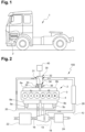
- Fig. 1 shows a vehicle 1 in the form of a truck in a partly cut side view.
- the vehicle 1 has an internal combustion engine 2 for the propulsion of the vehicle.
- an internal combustion engine system 100 is shown which is used in the vehicle of Fig. 1 or in any other vehicle comprising an internal combustion engine.
- the system 100 comprises an internal combustion engine 2 with a cylinder block 3 having a plurality of cylinders 4, e.g. six cylinders in an inline configuration.
- the cylinders 4 are divided into a first group of cylinders 4a and a second group of cylinders 4b. In the example shown, there are three cylinders 4 in the first group of cylinders 4a and three cylinders 4 in the second group of cylinders 4b.
- the invention is equally applicable to engines with a different number of cylinder, e.g. two, three, seven, etc.
- the number of cylinders in the first and second groups of cylinders 4a, 4b may be mutually different.
- the cylinder may have a configuration which different from an inline configuration, e.g. a V- configuration.
- the internal combustion engine 2 has a first intake manifold 6a for providing gas to the first group of cylinders 4a and a second intake manifold 6b for providing gas to the second group of cylinders 4b.
- the internal combustion engine 2 has also a first exhaust manifold 8a for receiving the exhaust gas emitted from the first group of cylinders 4a and a second exhaust manifold 8b for receiving the exhaust gas emitted from the second group of cylinders 4b.
- the first and second exhaust manifolds 8a, 8b may jointly form a single exhaust manifold.
- a part of the exhaust gas are led to a turbocharger 14 comprising a turbine 16 and an air compressor 18 and onward to an exhaust gas aftertreatment system 22.
- the turbocharger 14 can be used for the compression of the fresh air that is supplied to the first and second intake manifolds 6a, 6b through an air inlet line 10 and via a mixing unit 30 which will be detailed in the following paragraphs.
- the fresh air may be filtered in an air filter 24 before its compression, and may be cooled in a charged air cooler 26 after its compression.
- the exhaust gas aftertreatment system 22 usually comprises a plurality of exhaust gas aftertreatment units, such as e.g. a diesel oxidation catalyst, a particulate filter and a selective catalytic reactor (SCR).
- a diesel oxidation catalyst such as a diesel oxidation catalyst, a particulate filter and a selective catalytic reactor (SCR).
- SCR selective catalytic reactor
- a SCR unit is a means for converting nitrogen oxides by means of a catalyst into nitrogen and water.
- An optimal temperature range for these reactions is typically between approximately 250° Celsius and approximately 450° Celsius. This optimal operating temperature can be easily kept during normal (driving) operation modes of the engine.
- the system 100 For increasing the temperature of the exhaust gas streaming through the exhaust gas aftertreatment system 22, it is proposed in the present invention to operate the system 100 in a regeneration operating mode during which the cylinders 4 of the first group of cylinders 4a are controlled to be inactive, that means no fuel is injected into the cylinders 4 of the first group of cylinders 4a, and during which the cylinders 4 of the second group of cylinders 4b in contrast are controlled to be active. That means the load required for operating the engine in the regeneration operating mode is only provided by the second group of cylinders 4b. That in turn means that the exhaust gas from the second group of cylinders 4b has a significantly higher temperature than the exhaust gas from the first group of cylinders 4a, which in turn increases the overall temperature of the whole exhaust gas.
- the system 100 comprises an EGR line 20 which is branched off at the first exhaust manifold 8a, respectively the second exhaust manifold 8b, said EGR line 20 being fluidly connected to the mixing unit 30.
- the EGR line 20 is thus adapted to supply the mixing unit 30 with recirculated exhaust gas generated by the internal combustion engine 2.
- a first EGR valve 5a respectively a second EGR valve 5b, arranged downstream to the first exhaust manifold 8a, respectively to the second exhaust manifold 8b, may advantageously be provided for regulating the amount of recirculated exhaust gas that is supplied to the EGR line 20.
- the mixing unit 30 comprises a first inlet 31 fluidly connected to the EGR line 20, a second inlet 32 fluidly connected to the air inlet line 10, a first outlet 33 fluidly connected to the first intake manifold 6a via a first pipe 35 and a second outlet 34 fluidly connected to the second intake manifold 6b via a second pipe 36.
- the mixing unit 30 is adapted to control the flow of fresh air and exhaust gas supplied to the first and second intake manifolds 6a, 6b by the air inlet and EGR lines 10, 20.
- the mixing unit 30 is adapted to prevent a flow of fresh air to the first intake manifold 6a and a flow of exhaust gas to the second intake manifold 6b while allowing a flow of exhaust gas to the first intake manifold 6a and a flow of fresh air to the second intake manifold 6b.
- the mixing unit 30 is adapted to allow a flow of a mix of fresh air and exhaust gas to both the first and second intake manifolds 6a, 6b. This corresponds to a fully opened configuration of the mixing unit 30.
- the mixing unit 30 may prevent a flow of fresh air to the first intake manifold 6a but may allow a flow of exhaust gas to both the first and second intake manifolds 6a, 6b.
- the system 100 may advantageously comprise a controller 40 for controlling the opening, the closing and/or the partial opening of the mixing unit 30 depending on the operating mode of the system 100.
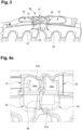
- Fig. 3 illustrates the upper portion of the internal combustion engine system 100 shown in Fig. 2 in a first embodiment of the invention.
- the mixing unit 30 consists in a four-way valve comprising a housing 37 defining an internal chamber 38.
- the internal chamber 38 having a first portion 38a in fluid communication with the first inlet 31 and the first outlet 33 of the four-way valve 30 and a second portion 38b in fluid communication with the second inlet 32 and the second outlet 34 of the four-way valve 30, the first and second portions 38a, 38b being separated by a central opening 38c.
- the four-way valve 30 further comprises a flap 39 having a substantially flat shape, and comprising a bottom end 39a and a top end 39b.
- the flap 39 is pivotally connected to the housing 37 around a pivot axis 39c that is substantially aligned with the central opening 38c.
- the length of the flap 39 is greater than the width of the central opening 38c.
- the bottom and top ends 39a, 39b of the flap 39 are close to the bottom and top abutment surfaces 37a, 37b but without contacting them.
- the bottom end 39a is sealingly in contact with a bottom internal surface 37 c of the housing 37.
- This bottom internal surface 37c substantially defines an hemi cylindrical part centered on the pivot axis 39c, the distance between said surface 37c and said pivot axis 39c being substantially equal to the length of the bottom end 39a.
- This sealed contact thus prevents a flow of gas between the first and second portions 38a, 38b in the bottom part of the internal chamber 38.
- the top end 39b is sufficiently distant from a top internal surface 37d to allow a flow of gas between the first and second portions 38a, 38b in a top part of the internal chamber 38.
- This first partially opened configuration of the valve 30 will thus lead to guide a small flow of exhaust gas through the second group of cylinders 4b, while preventing a flow of fresh air through the first group of cylinders 4a.
- FIG. 4c it is illustrated a second partially opened configuration of the valve 30, in which the flap 39 is an intermediate position between its position shown in Fig. 4b and its position shown in Fig. 4d .
- the bottom and top ends 39a, 39b of the flap 39 are sufficiently distant from the bottom and top abutment surfaces 37a, 37b and from the bottom and top internal surfaces 37c, 37d to allow a small flow of gas between the first and second portions 38a, 38b in both bottom and top parts of the internal chamber 38.
- This second partially opened configuration of the valve 30 will thus lead to guide a small flow of exhaust gas through the second group of cylinders 4b, while also allowing a small flow of fresh air through the first group of cylinders 4a.
- valve 30 In reference to Fig. 4d , it is illustrated the fully opened configuration of the valve 30.
- the bottom and top ends 39a, 39b of the flap 39 are sufficiently distant from the bottom and top abutment surfaces 37a, 37b and from the bottom and top internal surfaces 37c, 37d to allow a non-restricted flow of gas between the first and second portions 38a, 38b in both bottom and top parts of the internal chamber 38.
- This configuration of the valve 30 corresponds to the normal operating mode of the system 100 in which a mix of exhaust gas and fresh air is supplied to the cylinders 4 of the first and second groups of cylinders 4a, 4b.
- Fig. 5 it is illustrated an alternative embodiment of the four-way valve 30.
- the first and second portions 38a, 38b of the internal chamber 38 are separated by a hemi-cylindrical central opening 38c.
- the closure element 39 that plays the same role as the flap of the embodiment of Fig. 3 , comprises an hemi-cylindrical wall having substantially the same shape as the central opening 38c, said wall being rotatably movable in the internal chamber 38 between a first position, shown in dashed lines, in which it is angularly aligned with the central opening 38c to close it, and a second position, shown in solid lines, in which it is angularly offset from the central opening 38c to completely open it.
- the first position of the closure element 39 corresponds to the closed configuration of the valve 30 and the second position of the closure element 39 corresponds to the fully opened configuration of the valve 30.
- the closure element 39 may advantageously be disposed in an intermediate position (not shown) between said first and second positions, in which it is slightly angularly offset from the central opening 38c to partially open it. This intermediate position corresponds to a partially opened configuration of the valve 30.
Landscapes
- Engineering & Computer Science (AREA)
- Chemical & Material Sciences (AREA)
- Combustion & Propulsion (AREA)
- Mechanical Engineering (AREA)
- General Engineering & Computer Science (AREA)
- Exhaust-Gas Circulating Devices (AREA)
- Supercharger (AREA)
- Output Control And Ontrol Of Special Type Engine (AREA)
Description
- The invention relates to an internal combustion engine operable in at least two operating modes, respectively a normal operating mode and a regeneration operating mode.
- The invention can be applied in heavy-duty vehicles, such as trucks, buses and construction equipment. Although the invention will be described with respect to a truck, the invention is not restricted to this particular vehicle, but may also be used in other vehicles such as buses, construction equipment and passenger cars. The invention may also be used on other transportation means such as ships and boats.
- For a vehicle internal combustion engine, such as a diesel type engine for a heavy-duty vehicle, an exhaust after treatment system (EATS) is usually provided to reduce emissions, e.g. of nitrogen oxides (NOx). Such a system, which may include units such as a selective catalytic reduction (SCR) converter, requires exhaust gas temperatures that are relatively high in order to provide an efficient emission reduction.
- However, measures to reduce fuel consumption may reduce the heat loss from the engine to the EATS. Therefore, particularly at low load operation, cold ambient temperatures, and/or cold start events, the EATS might not get enough heat to operate efficiently.
- To increase the temperature of the exhaust gases of an engine and regenerate EATS components, a known solution consists to deactivate some of the engine cylinders. This result in an increase in the amount of fuel sent to the other (active) cylinders to compensate for the decrease in power due to the deactivation of the cylinders and to maintain the same torque. As more fuel is burned, the exhaust gas temperature is automatically higher.
- Such a solution has been disclosed in
US 4,303,053 andUS 2016/0298557 . - However, the solution proposed in this prior art leads to add much complexity in the structure of the engine and decrease the free space around the engine, which is a major drawback during the mounting process of the vehicle.
- An object of the invention is to provide an internal combustion engine system operable in at least two operating modes, respectively a normal operating mode and a regeneration operating mode, in which some of the engine cylinders are deactivated, and in which the drawbacks of the known solutions are avoided.
- The object is achieved by a system according to claim 1. Thus, the object is achieved by an internal combustion engine system Internal combustion engine system, comprising:
- an internal combustion engine comprising a cylinder block housing a plurality of cylinders, a first intake manifold connected to a first group of cylinders, a second distinct intake manifold connected to a second group of cylinders and a first, respectively a second, exhaust manifold for receiving the exhaust gas emitted from the first, respectively the second, group of cylinders ;
- an air inlet line ;
- an EGR line connected to the first and second exhaust manifolds ;
- wherein the internal combustion engine system is operable in at least two operating modes, respectively a normal operating mode in which all cylinders are supplied with fuel and a regeneration operating mode, in which the cylinders of the first group of cylinders are no longer supplied with fuel,
- characterized in that:
- the system also includes a mixing unit comprising a four-way valve, said four-way valve having a first inlet connected to the EGR line, a second inlet connected to the air inlet line, a first outlet connected to the first intake manifold and a second outlet connected to the second intake manifold;
- the four-way valve is designed so that, in said normal operating mode, the intake gases supplied to the first intake manifold and to the second intake manifold have approximately the same proportion of exhaust gas and so that, in said regeneration operating mode, the intake gas supplied to the first intake manifold only includes exhaust gas;
- the four-way valve comprises a housing defining an internal chamber, the internal chamber having a first portion in fluid communication with the first inlet and the first outlet of the four-way valve and a second portion in fluid communication with the second inlet and the second outlet of the four-way valve, the first and second portions being separated by a central opening, the central opening being selectively closed by a closure element.
- Thus configured, the system of the present invention permits to control the flow of fresh air and exhaust gas supplied to the engine cylinders by the use of a mixing unit upstream of the intake manifolds of the engine. This mixing unit thus allows the supply of fresh air inside deactivated engine cylinders to be cut off during a regeneration operating mode while maintaining a supply of a mix of fresh air and exhaust gas inside all engine cylinders during a normal operating mode. This mixing unit has the advantage relative to the prior art solutions to maintain a relatively simple structure for the engine and to have a lower impact on the dimensions of the whole system.
- According to a further aspect of the invention, the object is achieved by a vehicle according to claim 12.
- Further advantages and advantageous features of the invention are disclosed in the following description and in the dependent claims.
- With reference to the appended drawings, below follows a more detailed description of embodiments of the invention cited as examples.
- In the drawings:
-
Fig. 1 is a side view of a truck comprising an internal combustion engine, and -
Fig. 2 is a schematic view of an internal combustion engine system according to the invention, belonging to the vehicle ofFig. 1 ; -
Fig. 3 is a cross-sectional perspective view of the upper portion of the internal combustion engine system shown inFig. 2 in a first embodiment of the invention; -
Fig. 4a is an enlarged view of the mixing unit of the internal combustion engine system shown inFig. 3 , the mixing unit being in a closed configuration; -
Fig. 4b is a view similar toFig. 4a , the mixing unit being in a first partially opened configuration; -
Fig. 4c is a view similar toFig. 4a , the mixing unit being in a second partially opened configuration; -
Fig. 4d is a view similar toFig. 4a , the mixing unit being in a full opened configuration; -
Fig. 5 is a cross-sectional view of the mixing unit of the internal combustion engine system shown inFig. 2 in a second embodiment of the invention. -
Fig. 1 shows a vehicle 1 in the form of a truck in a partly cut side view. The vehicle 1 has aninternal combustion engine 2 for the propulsion of the vehicle. - In reference to
Fig. 2 , an internalcombustion engine system 100 is shown which is used in the vehicle ofFig. 1 or in any other vehicle comprising an internal combustion engine. Thesystem 100 comprises aninternal combustion engine 2 with acylinder block 3 having a plurality ofcylinders 4, e.g. six cylinders in an inline configuration. Thecylinders 4 are divided into a first group ofcylinders 4a and a second group ofcylinders 4b. In the example shown, there are threecylinders 4 in the first group ofcylinders 4a and threecylinders 4 in the second group ofcylinders 4b. It should be noted that the invention is equally applicable to engines with a different number of cylinder, e.g. two, three, seven, etc. Also, the number of cylinders in the first and second groups ofcylinders - Furthermore, the
internal combustion engine 2 has a first intake manifold 6a for providing gas to the first group ofcylinders 4a and asecond intake manifold 6b for providing gas to the second group ofcylinders 4b. Theinternal combustion engine 2 has also afirst exhaust manifold 8a for receiving the exhaust gas emitted from the first group ofcylinders 4a and asecond exhaust manifold 8b for receiving the exhaust gas emitted from the second group ofcylinders 4b. In an alternative embodiment (not shown), the first andsecond exhaust manifolds - A part of the exhaust gas are led to a
turbocharger 14 comprising aturbine 16 and anair compressor 18 and onward to an exhaustgas aftertreatment system 22. Theturbocharger 14 can be used for the compression of the fresh air that is supplied to the first andsecond intake manifolds 6a, 6b through anair inlet line 10 and via amixing unit 30 which will be detailed in the following paragraphs. The fresh air may be filtered in anair filter 24 before its compression, and may be cooled in a chargedair cooler 26 after its compression. - The exhaust
gas aftertreatment system 22 usually comprises a plurality of exhaust gas aftertreatment units, such as e.g. a diesel oxidation catalyst, a particulate filter and a selective catalytic reactor (SCR). - A SCR unit is a means for converting nitrogen oxides by means of a catalyst into nitrogen and water. An optimal temperature range for these reactions is typically between approximately 250° Celsius and approximately 450° Celsius. This optimal operating temperature can be easily kept during normal (driving) operation modes of the engine.
- However, during idle or motoring engine operation modes of the
internal combustion engine 2, the temperature of the exhaust gas drops. The reason for that is that fresh air at ambient temperature is fed to theintake manifolds 6a, 6b, even if combustion is reduced considerably (as in the idle engine operation mode) or no combustion takes place at all (as in the motoring engine operation mode). This in turn means that theinternal combustion engine 2 is simply pumping fresh and cool air to theexhaust manifolds gas aftertreatment system 22. This cool air causes the exhaustgas aftertreatment system 22 to cool down rapidly below its optimal operating temperature, which in turn results in poor or no exhaust gas purification, so that the required emission levels cannot be achieved. - For increasing the temperature of the exhaust gas streaming through the exhaust
gas aftertreatment system 22, it is proposed in the present invention to operate thesystem 100 in a regeneration operating mode during which thecylinders 4 of the first group ofcylinders 4a are controlled to be inactive, that means no fuel is injected into thecylinders 4 of the first group ofcylinders 4a, and during which thecylinders 4 of the second group ofcylinders 4b in contrast are controlled to be active. That means the load required for operating the engine in the regeneration operating mode is only provided by the second group ofcylinders 4b. That in turn means that the exhaust gas from the second group ofcylinders 4b has a significantly higher temperature than the exhaust gas from the first group ofcylinders 4a, which in turn increases the overall temperature of the whole exhaust gas. - Furthermore, the
system 100 comprises anEGR line 20 which is branched off at thefirst exhaust manifold 8a, respectively thesecond exhaust manifold 8b, saidEGR line 20 being fluidly connected to the mixingunit 30. TheEGR line 20 is thus adapted to supply themixing unit 30 with recirculated exhaust gas generated by theinternal combustion engine 2. Afirst EGR valve 5a, respectively asecond EGR valve 5b, arranged downstream to thefirst exhaust manifold 8a, respectively to thesecond exhaust manifold 8b, may advantageously be provided for regulating the amount of recirculated exhaust gas that is supplied to theEGR line 20. - The mixing
unit 30 comprises afirst inlet 31 fluidly connected to theEGR line 20, asecond inlet 32 fluidly connected to theair inlet line 10, afirst outlet 33 fluidly connected to the first intake manifold 6a via afirst pipe 35 and asecond outlet 34 fluidly connected to thesecond intake manifold 6b via asecond pipe 36. The mixingunit 30 is adapted to control the flow of fresh air and exhaust gas supplied to the first andsecond intake manifolds 6a, 6b by the air inlet andEGR lines system 100, the mixingunit 30 is adapted to prevent a flow of fresh air to the first intake manifold 6a and a flow of exhaust gas to thesecond intake manifold 6b while allowing a flow of exhaust gas to the first intake manifold 6a and a flow of fresh air to thesecond intake manifold 6b. This corresponds to a closed configuration of the mixingunit 30. On the contrary, in the normal operating mode of thesystem 100, the mixingunit 30 is adapted to allow a flow of a mix of fresh air and exhaust gas to both the first andsecond intake manifolds 6a, 6b. This corresponds to a fully opened configuration of the mixingunit 30. Furthermore, in a partially opened configuration of the mixingunit 30, the mixingunit 30 may prevent a flow of fresh air to the first intake manifold 6a but may allow a flow of exhaust gas to both the first andsecond intake manifolds 6a, 6b. Thesystem 100 may advantageously comprise acontroller 40 for controlling the opening, the closing and/or the partial opening of the mixingunit 30 depending on the operating mode of thesystem 100. -
Fig. 3 illustrates the upper portion of the internalcombustion engine system 100 shown inFig. 2 in a first embodiment of the invention. In this embodiment, and as best shown inFig. 4d , the mixingunit 30 consists in a four-way valve comprising ahousing 37 defining aninternal chamber 38. Theinternal chamber 38 having afirst portion 38a in fluid communication with thefirst inlet 31 and thefirst outlet 33 of the four-way valve 30 and asecond portion 38b in fluid communication with thesecond inlet 32 and thesecond outlet 34 of the four-way valve 30, the first andsecond portions central opening 38c. The four-way valve 30 further comprises aflap 39 having a substantially flat shape, and comprising abottom end 39a and atop end 39b. Theflap 39 is pivotally connected to thehousing 37 around apivot axis 39c that is substantially aligned with thecentral opening 38c. The length of theflap 39 is greater than the width of thecentral opening 38c. Thus, as illustrated inFig. 4a , when the bottom andtop ends flap 39 are substantially aligned with thecentral opening 38c, theflap 39 abuts against abottom abutment surface 37a and atop abutment surface 37b defined by thehousing 37 and closes thecentral opening 38c. In this closed configuration of thevalve 30, the fresh air supplied by theair inlet line 10 is guided through the second group ofcylinders 4b only. The intake of fresh air for the first group ofcylinders 4a is thus controlled to be zero or almost zero. In the same time, the entire flow of exhaust gas supplied by theEGR line 20 is guided through the first group ofcylinders 4a only. This closed configuration of thevalve 30 will thus lead to an increase of the overall temperature of the whole exhaust gas when thecylinders 4 of the first group ofcylinders 4a are controlled to be inactive and thecylinders 4 of the second group ofcylinders 4b are controlled to be active. - In reference to
Fig. 4b , it is illustrated a first partially opened configuration of thevalve 30, in which theflap 39 is an intermediate position between its position shown inFig. 4a and its position shown inFig. 4d . In this position, the bottom andtop ends flap 39 are close to the bottom andtop abutment surfaces bottom end 39a is sealingly in contact with a bottominternal surface 37 c of thehousing 37. This bottominternal surface 37c substantially defines an hemi cylindrical part centered on thepivot axis 39c, the distance between saidsurface 37c and saidpivot axis 39c being substantially equal to the length of thebottom end 39a. This sealed contact thus prevents a flow of gas between the first andsecond portions internal chamber 38. In the same time, thetop end 39b is sufficiently distant from a topinternal surface 37d to allow a flow of gas between the first andsecond portions internal chamber 38. This first partially opened configuration of thevalve 30 will thus lead to guide a small flow of exhaust gas through the second group ofcylinders 4b, while preventing a flow of fresh air through the first group ofcylinders 4a. - In reference to
Fig. 4c , it is illustrated a second partially opened configuration of thevalve 30, in which theflap 39 is an intermediate position between its position shown inFig. 4b and its position shown inFig. 4d . In this position, the bottom andtop ends flap 39 are sufficiently distant from the bottom andtop abutment surfaces internal surfaces second portions internal chamber 38. This second partially opened configuration of thevalve 30 will thus lead to guide a small flow of exhaust gas through the second group ofcylinders 4b, while also allowing a small flow of fresh air through the first group ofcylinders 4a. - In reference to
Fig. 4d , it is illustrated the fully opened configuration of thevalve 30. In this configuration, the bottom andtop ends flap 39 are sufficiently distant from the bottom andtop abutment surfaces internal surfaces second portions internal chamber 38. This configuration of thevalve 30 corresponds to the normal operating mode of thesystem 100 in which a mix of exhaust gas and fresh air is supplied to thecylinders 4 of the first and second groups ofcylinders - In reference to
Fig. 5 , it is illustrated an alternative embodiment of the four-way valve 30. In this embodiment, the first andsecond portions internal chamber 38 are separated by a hemi-cylindricalcentral opening 38c. Theclosure element 39, that plays the same role as the flap of the embodiment ofFig. 3 , comprises an hemi-cylindrical wall having substantially the same shape as thecentral opening 38c, said wall being rotatably movable in theinternal chamber 38 between a first position, shown in dashed lines, in which it is angularly aligned with thecentral opening 38c to close it, and a second position, shown in solid lines, in which it is angularly offset from thecentral opening 38c to completely open it. The first position of theclosure element 39 corresponds to the closed configuration of thevalve 30 and the second position of theclosure element 39 corresponds to the fully opened configuration of thevalve 30. Theclosure element 39 may advantageously be disposed in an intermediate position (not shown) between said first and second positions, in which it is slightly angularly offset from thecentral opening 38c to partially open it. This intermediate position corresponds to a partially opened configuration of thevalve 30. - It is to be understood that the present invention is not limited to the embodiments described above and illustrated in the drawings; rather, the skilled person will recognize that many changes and modifications may be made within the scope of the appended claims.
Claims (12)
- Internal combustion engine system (100), comprising :- an internal combustion engine (2) comprising a cylinder block (3) housing a plurality of cylinders (4), a first intake manifold (6a) connected to a first group of cylinders (4a), a second distinct intake manifold (6b) connected to a second group of cylinders (4b) and a first, respectively a second, exhaust manifold (8a, 8b) for receiving the exhaust gas emitted from the first, respectively the second, group of cylinders (4a, 4b);- an air inlet line (10);- an EGR line (20) connected to the first and second exhaust manifolds (8a, 8b);wherein the internal combustion engine system is operable in at least two operating modes, respectively a normal operating mode in which all cylinders are supplied with fuel and a regeneration operating mode, in which the cylinders of the first group of cylinders (4a) are no longer supplied with fuel,characterized in that:- the system also includes a mixing unit (30) comprising a four-way valve, said four-way valve (30) having a first inlet (31) connected to the EGR line (20), a second inlet (32) connected to the air inlet line (10), a first outlet (33) connected to the first intake manifold (6a) and a second outlet (34) connected to the second intake manifold (6b);- the four-way valve is designed so that, in said normal operating mode, the intake gases supplied to the first intake manifold (6a) and to the second intake manifold (6b) have approximately the same proportion of exhaust gas and so that, in said regeneration operating mode, the intake gas supplied to the first intake manifold (6a) only includes exhaust gas, andin that the four-way valve (30) comprises a housing (37) defining an internal chamber (38), the internal chamber (38) having a first portion (38a) in fluid communication with the first inlet (31) and the first outlet (33) of the four-way valve (30) and a second portion (38b) in fluid communication with the second inlet (32) and the second outlet (34) of the four-way valve (30), the first and second portions (38a, 38b) being separated by a central opening (38c), the central opening (38c) being selectively closed by a closure element (39).
- The system (100) according to claim 1, characterized in that the four-way valve is controlled so that, in said regeneration operating mode, the intake gas supplied to the second intake manifold (6b) includes only fresh air or a mixture of fresh air and exhaust gas.
- The system (100) according to claim 1 or claim 2, characterized in that the closure element (39) comprises a flap that is rotatably movable inside the internal chamber (38).
- The system (100) according to claim 3, characterized in that the flap has a bottom end (39a) and a top end (39b), said flap (39) being rotatably movable between a first position in which its bottom end (39a), respectively its top end (39b), abuts against a bottom abutment surface (37a), respectively a top abutment surface (37b), defined by the housing (37) and in which it closes the central opening (38c), a second position in which its bottom and top ends (39a, 39b) are far from the bottom and top abutment surfaces (37a, 37b) and in which it completely opens the central opening (38c), and preferably an intermediate position between the first and second positions in which its bottom and top ends (39a, 39b) are close to said bottom and top abutment surfaces (37a, 37b) and in which it opens the central opening (38c) in a top part thereof that is close to the top abutment surface (37b) while closing said central opening (38c) in a bottom part thereof that is close to the bottom abutment surface (37a).
- The system (100) according to claim 4, characterized in that, in the intermediate position of the flap (39), its bottom end (39a) is sealingly in contact with a bottom internal surface (37c) of the housing (37), thus preventing a flow of gas between the first and second portions (38a, 38b) of the internal chamber (38) through the central opening (38c) in a bottom part thereof, and its top end (39b) is distant from a top internal surface (37d) of the housing (37), thus allowing a flow of gas between said first and second portions (38a, 38b) through the central opening (38c) in a top part thereof.
- The system (100) according to claim 1 or claim 2, characterized in that the closure element (39) comprises a hemi-cylindrical wall having substantially the same shape as the central opening (38c), said wall (39) being rotatably movable inside the internal chamber (38).
- The system (100) according to claim 6, characterized in that the closure element (39) is movable between a first position, in which it is angularly aligned with the central opening (38c) to close it, a second position, in which it is angularly offset from the central opening (38c) to completely open it, and preferably an intermediate position between the first and second positions in which it is slightly angularly offset from the central opening (38c) to partially open it.
- The system (100) according to any previous claim, characterized in that it further comprises a controller (40) for controlling the opening, the closing and/or the partial opening of the four-way valve (30).
- The system (100) according to any preceding claim, characterized in that an EGR valve (5a, 5b) is arranged downstream of the first, respectively the second, exhaust manifold (8a, 8b) on the path of exhaust gas flowing towards the EGR line (20), said EGR valves (5a, 5b) controlling the flow of exhaust gas through the EGR line (20).
- The system (100) according to any preceding claim, characterized in that the first and second exhaust manifolds (8a, 8b) jointly form a single exhaust manifold.
- The system (100) according to any preceding claim, characterized in that the system (100) includes a turbocharger (14) comprising an air compressor (18) and a turbine (16) for driving said compressor (18), the turbine (16) being arranged to be driven by exhaust gas flowing from the first and second exhaust manifolds (8a, 8b) to an exhaust after treatment system (22), the air compressor (18) being arranged to supply compressed air to the air inlet line (10).
- Vehicle (1) comprising an internal combustion engine system (100) according to any preceding claim.
Applications Claiming Priority (1)
| Application Number | Priority Date | Filing Date | Title |
|---|---|---|---|
| PCT/EP2019/078906 WO2021078379A1 (en) | 2019-10-23 | 2019-10-23 | Internal combustion engine system operable in at least two operating modes |
Publications (3)
| Publication Number | Publication Date |
|---|---|
| EP4048877A1 EP4048877A1 (en) | 2022-08-31 |
| EP4048877C0 EP4048877C0 (en) | 2024-07-24 |
| EP4048877B1 true EP4048877B1 (en) | 2024-07-24 |
Family
ID=68342925
Family Applications (1)
| Application Number | Title | Priority Date | Filing Date |
|---|---|---|---|
| EP19794139.6A Active EP4048877B1 (en) | 2019-10-23 | 2019-10-23 | Internal combustion engine system operable in at least two operating modes |
Country Status (4)
| Country | Link |
|---|---|
| US (1) | US11761408B2 (en) |
| EP (1) | EP4048877B1 (en) |
| CN (1) | CN114555924B (en) |
| WO (1) | WO2021078379A1 (en) |
Families Citing this family (2)
| Publication number | Priority date | Publication date | Assignee | Title |
|---|---|---|---|---|
| EP4080035A1 (en) * | 2021-04-21 | 2022-10-26 | Volvo Truck Corporation | Internal combustion engine system |
| EP4116564B1 (en) * | 2021-04-22 | 2024-12-25 | Volvo Truck Corporation | Internal combustion engine system operable in at least two operating modes |
Citations (1)
| Publication number | Priority date | Publication date | Assignee | Title |
|---|---|---|---|---|
| US11512672B2 (en) * | 2021-04-22 | 2022-11-29 | Volvo Truck Corporation | Internal combustion engine system operable in at least two operating modes |
Family Cites Families (18)
| Publication number | Priority date | Publication date | Assignee | Title |
|---|---|---|---|---|
| JPS5853182B2 (en) | 1979-05-07 | 1983-11-28 | 日産自動車株式会社 | Exhaust recirculation device for engine with cylinder number control |
| GB2304602A (en) * | 1995-08-26 | 1997-03-26 | Ford Motor Co | Engine with cylinder deactivation |
| JP4056286B2 (en) * | 2002-04-19 | 2008-03-05 | 三洋電機株式会社 | Control device for engine drive device |
| JP2004162665A (en) * | 2002-11-15 | 2004-06-10 | Denso Corp | Exhaust gas recirculation device |
| GB0320986D0 (en) * | 2003-09-08 | 2003-10-08 | Ricardo Uk Ltd | Automotive turbo charger systems |
| US8468813B2 (en) * | 2007-03-16 | 2013-06-25 | Tenneco Automotive Operating Company Inc. | Snap-action valve for exhaust system |
| US8635985B2 (en) * | 2008-01-07 | 2014-01-28 | Mcalister Technologies, Llc | Integrated fuel injectors and igniters and associated methods of use and manufacture |
| FR2943722B1 (en) * | 2009-03-30 | 2011-05-27 | Melchior Jean F | SUPERIOR INTERNAL COMBUSTION ENGINE |
| DE102012107839B4 (en) * | 2012-08-24 | 2015-09-24 | Eberspächer Exhaust Technology GmbH & Co. KG | Four-way exhaust flap |
| CN104755739B (en) * | 2012-10-30 | 2018-04-10 | 博格华纳公司 | Internal combustion engine system and the method for controlling the system |
| US20140165963A1 (en) * | 2012-12-13 | 2014-06-19 | J. Michael Langham | Hydraulic Engine with One or More of Improved Transmission Control, Valve, and Fuel Injection Features |
| EP3077648B1 (en) | 2013-11-29 | 2019-01-30 | Volvo Construction Equipment AB | An internal combustion engine and a method for controlling an internal combustion engine |
| FR3015578B1 (en) * | 2013-12-19 | 2016-01-29 | Valeo Sys Controle Moteur Sas | AIR INTAKE SYSTEM FOR THERMAL ENGINE |
| DE102016203823B3 (en) * | 2016-03-09 | 2017-08-24 | Ford Global Technologies, Llc | Method for operating a exhaust-gas-charged internal combustion engine with partial deactivation |
| US20160252055A1 (en) * | 2016-05-09 | 2016-09-01 | Electro-Motive Diesel, Inc. | Self cleaning exhaust gas recirculation cooler system for locomotive engines |
| FR3054602A1 (en) * | 2016-07-29 | 2018-02-02 | IFP Energies Nouvelles | DEVICE AND METHOD FOR CONTROLLING THE JOINT INTRODUCTION OF AIR AND EXHAUST GAS TO THE ADMISSION OF A SUPERIOR INTERNAL COMBUSTION ENGINE. |
| US10287941B2 (en) * | 2016-08-30 | 2019-05-14 | Ford Global Technologies, Llc | Engine exhaust system control |
| EP4080035A1 (en) * | 2021-04-21 | 2022-10-26 | Volvo Truck Corporation | Internal combustion engine system |
-
2019
- 2019-10-23 EP EP19794139.6A patent/EP4048877B1/en active Active
- 2019-10-23 WO PCT/EP2019/078906 patent/WO2021078379A1/en not_active Ceased
- 2019-10-23 CN CN201980101350.8A patent/CN114555924B/en active Active
- 2019-10-23 US US17/753,856 patent/US11761408B2/en active Active
Patent Citations (1)
| Publication number | Priority date | Publication date | Assignee | Title |
|---|---|---|---|---|
| US11512672B2 (en) * | 2021-04-22 | 2022-11-29 | Volvo Truck Corporation | Internal combustion engine system operable in at least two operating modes |
Also Published As
| Publication number | Publication date |
|---|---|
| WO2021078379A1 (en) | 2021-04-29 |
| EP4048877A1 (en) | 2022-08-31 |
| US11761408B2 (en) | 2023-09-19 |
| CN114555924A (en) | 2022-05-27 |
| CN114555924B (en) | 2024-08-09 |
| EP4048877C0 (en) | 2024-07-24 |
| US20220333560A1 (en) | 2022-10-20 |
Similar Documents
| Publication | Publication Date | Title |
|---|---|---|
| EP3559431B1 (en) | A method for controlling an internal combustion engine | |
| US20100154412A1 (en) | Apparatus and method for providing thermal management of a system | |
| US20220235725A1 (en) | Cylinder head with integrated catalyst | |
| EP2071144B1 (en) | Piston-type internal combustion engine | |
| US11536227B2 (en) | Internal combustion engine system | |
| US11761408B2 (en) | Internal combustion engine system operable in at least two operating modes | |
| US11512672B2 (en) | Internal combustion engine system operable in at least two operating modes | |
| US8511065B2 (en) | Engine with emissions control arrangement and method of controlling engine emissions | |
| WO2010123411A1 (en) | Method and arrangement for recirculation of exhaust gases of a combustion engine | |
| CN112368469A (en) | Improved method for controlling an internal combustion engine | |
| US20090178396A1 (en) | EGR catalyzation with reduced EGR heating | |
| JP7472846B2 (en) | Engine System | |
| CN111663983A (en) | Method for operating an SCR catalyst having a bypass flow channel | |
| EP3527794B1 (en) | Pollutant abatement system of an internal combustion engine and internal combustion engine comprising the abatement system | |
| JP2025127643A (en) | Engine System | |
| JPH10141148A (en) | Exhaust gas recirculation device | |
| KR101324437B1 (en) | System for clarifying exhaust gas of direct injection engines and control method thereof |
Legal Events
| Date | Code | Title | Description |
|---|---|---|---|
| STAA | Information on the status of an ep patent application or granted ep patent |
Free format text: STATUS: UNKNOWN |
|
| STAA | Information on the status of an ep patent application or granted ep patent |
Free format text: STATUS: THE INTERNATIONAL PUBLICATION HAS BEEN MADE |
|
| PUAI | Public reference made under article 153(3) epc to a published international application that has entered the european phase |
Free format text: ORIGINAL CODE: 0009012 |
|
| STAA | Information on the status of an ep patent application or granted ep patent |
Free format text: STATUS: REQUEST FOR EXAMINATION WAS MADE |
|
| 17P | Request for examination filed |
Effective date: 20220505 |
|
| AK | Designated contracting states |
Kind code of ref document: A1 Designated state(s): AL AT BE BG CH CY CZ DE DK EE ES FI FR GB GR HR HU IE IS IT LI LT LU LV MC MK MT NL NO PL PT RO RS SE SI SK SM TR |
|
| DAV | Request for validation of the european patent (deleted) | ||
| DAX | Request for extension of the european patent (deleted) | ||
| REG | Reference to a national code |
Ref legal event code: R079 Free format text: PREVIOUS MAIN CLASS: F02B0027020000 Ref country code: DE Ref document number: 602019055793 Country of ref document: DE Ipc: F02D0041000000 |
|
| GRAP | Despatch of communication of intention to grant a patent |
Free format text: ORIGINAL CODE: EPIDOSNIGR1 |
|
| STAA | Information on the status of an ep patent application or granted ep patent |
Free format text: STATUS: GRANT OF PATENT IS INTENDED |
|
| RIC1 | Information provided on ipc code assigned before grant |
Ipc: F02M 26/43 20160101ALI20240327BHEP Ipc: F02M 26/21 20160101ALI20240327BHEP Ipc: F02M 26/19 20160101ALI20240327BHEP Ipc: F01N 13/10 20100101ALI20240327BHEP Ipc: F01N 9/00 20060101ALI20240327BHEP Ipc: F02M 26/05 20160101ALI20240327BHEP Ipc: F02M 35/108 20060101ALI20240327BHEP Ipc: F02M 35/10 20060101ALI20240327BHEP Ipc: F02D 17/02 20060101ALI20240327BHEP Ipc: F02D 41/02 20060101ALI20240327BHEP Ipc: F02D 41/00 20060101AFI20240327BHEP |
|
| INTG | Intention to grant announced |
Effective date: 20240424 |
|
| GRAS | Grant fee paid |
Free format text: ORIGINAL CODE: EPIDOSNIGR3 |
|
| GRAA | (expected) grant |
Free format text: ORIGINAL CODE: 0009210 |
|
| STAA | Information on the status of an ep patent application or granted ep patent |
Free format text: STATUS: THE PATENT HAS BEEN GRANTED |
|
| AK | Designated contracting states |
Kind code of ref document: B1 Designated state(s): AL AT BE BG CH CY CZ DE DK EE ES FI FR GB GR HR HU IE IS IT LI LT LU LV MC MK MT NL NO PL PT RO RS SE SI SK SM TR |
|
| REG | Reference to a national code |
Ref country code: GB Ref legal event code: FG4D |
|
| REG | Reference to a national code |
Ref country code: CH Ref legal event code: EP |
|
| REG | Reference to a national code |
Ref country code: DE Ref legal event code: R096 Ref document number: 602019055793 Country of ref document: DE |
|
| REG | Reference to a national code |
Ref country code: IE Ref legal event code: FG4D |
|
| U01 | Request for unitary effect filed |
Effective date: 20240725 |
|
| U07 | Unitary effect registered |
Designated state(s): AT BE BG DE DK EE FI FR IT LT LU LV MT NL PT SE SI Effective date: 20240809 |
|
| U20 | Renewal fee for the european patent with unitary effect paid |
Year of fee payment: 6 Effective date: 20240814 |
|
| PG25 | Lapsed in a contracting state [announced via postgrant information from national office to epo] |
Ref country code: NO Free format text: LAPSE BECAUSE OF FAILURE TO SUBMIT A TRANSLATION OF THE DESCRIPTION OR TO PAY THE FEE WITHIN THE PRESCRIBED TIME-LIMIT Effective date: 20241024 |
|
| PG25 | Lapsed in a contracting state [announced via postgrant information from national office to epo] |
Ref country code: PL Free format text: LAPSE BECAUSE OF FAILURE TO SUBMIT A TRANSLATION OF THE DESCRIPTION OR TO PAY THE FEE WITHIN THE PRESCRIBED TIME-LIMIT Effective date: 20240724 Ref country code: GR Free format text: LAPSE BECAUSE OF FAILURE TO SUBMIT A TRANSLATION OF THE DESCRIPTION OR TO PAY THE FEE WITHIN THE PRESCRIBED TIME-LIMIT Effective date: 20241025 |
|
| PG25 | Lapsed in a contracting state [announced via postgrant information from national office to epo] |
Ref country code: IS Free format text: LAPSE BECAUSE OF FAILURE TO SUBMIT A TRANSLATION OF THE DESCRIPTION OR TO PAY THE FEE WITHIN THE PRESCRIBED TIME-LIMIT Effective date: 20241124 |
|
| PG25 | Lapsed in a contracting state [announced via postgrant information from national office to epo] |
Ref country code: HR Free format text: LAPSE BECAUSE OF FAILURE TO SUBMIT A TRANSLATION OF THE DESCRIPTION OR TO PAY THE FEE WITHIN THE PRESCRIBED TIME-LIMIT Effective date: 20240724 |
|
| PG25 | Lapsed in a contracting state [announced via postgrant information from national office to epo] |
Ref country code: ES Free format text: LAPSE BECAUSE OF FAILURE TO SUBMIT A TRANSLATION OF THE DESCRIPTION OR TO PAY THE FEE WITHIN THE PRESCRIBED TIME-LIMIT Effective date: 20240724 Ref country code: RS Free format text: LAPSE BECAUSE OF FAILURE TO SUBMIT A TRANSLATION OF THE DESCRIPTION OR TO PAY THE FEE WITHIN THE PRESCRIBED TIME-LIMIT Effective date: 20241024 |
|
| PG25 | Lapsed in a contracting state [announced via postgrant information from national office to epo] |
Ref country code: RS Free format text: LAPSE BECAUSE OF FAILURE TO SUBMIT A TRANSLATION OF THE DESCRIPTION OR TO PAY THE FEE WITHIN THE PRESCRIBED TIME-LIMIT Effective date: 20241024 Ref country code: PL Free format text: LAPSE BECAUSE OF FAILURE TO SUBMIT A TRANSLATION OF THE DESCRIPTION OR TO PAY THE FEE WITHIN THE PRESCRIBED TIME-LIMIT Effective date: 20240724 Ref country code: NO Free format text: LAPSE BECAUSE OF FAILURE TO SUBMIT A TRANSLATION OF THE DESCRIPTION OR TO PAY THE FEE WITHIN THE PRESCRIBED TIME-LIMIT Effective date: 20241024 Ref country code: IS Free format text: LAPSE BECAUSE OF FAILURE TO SUBMIT A TRANSLATION OF THE DESCRIPTION OR TO PAY THE FEE WITHIN THE PRESCRIBED TIME-LIMIT Effective date: 20241124 Ref country code: HR Free format text: LAPSE BECAUSE OF FAILURE TO SUBMIT A TRANSLATION OF THE DESCRIPTION OR TO PAY THE FEE WITHIN THE PRESCRIBED TIME-LIMIT Effective date: 20240724 Ref country code: GR Free format text: LAPSE BECAUSE OF FAILURE TO SUBMIT A TRANSLATION OF THE DESCRIPTION OR TO PAY THE FEE WITHIN THE PRESCRIBED TIME-LIMIT Effective date: 20241025 Ref country code: ES Free format text: LAPSE BECAUSE OF FAILURE TO SUBMIT A TRANSLATION OF THE DESCRIPTION OR TO PAY THE FEE WITHIN THE PRESCRIBED TIME-LIMIT Effective date: 20240724 |
|
| PG25 | Lapsed in a contracting state [announced via postgrant information from national office to epo] |
Ref country code: RO Free format text: LAPSE BECAUSE OF FAILURE TO SUBMIT A TRANSLATION OF THE DESCRIPTION OR TO PAY THE FEE WITHIN THE PRESCRIBED TIME-LIMIT Effective date: 20240724 Ref country code: SM Free format text: LAPSE BECAUSE OF FAILURE TO SUBMIT A TRANSLATION OF THE DESCRIPTION OR TO PAY THE FEE WITHIN THE PRESCRIBED TIME-LIMIT Effective date: 20240724 |
|
| PG25 | Lapsed in a contracting state [announced via postgrant information from national office to epo] |
Ref country code: CZ Free format text: LAPSE BECAUSE OF FAILURE TO SUBMIT A TRANSLATION OF THE DESCRIPTION OR TO PAY THE FEE WITHIN THE PRESCRIBED TIME-LIMIT Effective date: 20240724 |
|
| PG25 | Lapsed in a contracting state [announced via postgrant information from national office to epo] |
Ref country code: SK Free format text: LAPSE BECAUSE OF FAILURE TO SUBMIT A TRANSLATION OF THE DESCRIPTION OR TO PAY THE FEE WITHIN THE PRESCRIBED TIME-LIMIT Effective date: 20240724 |
|
| PLBE | No opposition filed within time limit |
Free format text: ORIGINAL CODE: 0009261 |
|
| STAA | Information on the status of an ep patent application or granted ep patent |
Free format text: STATUS: NO OPPOSITION FILED WITHIN TIME LIMIT |
|
| REG | Reference to a national code |
Ref country code: CH Ref legal event code: PL |
|
| GBPC | Gb: european patent ceased through non-payment of renewal fee |
Effective date: 20241024 |
|
| 26N | No opposition filed |
Effective date: 20250425 |
|
| PG25 | Lapsed in a contracting state [announced via postgrant information from national office to epo] |
Ref country code: MC Free format text: LAPSE BECAUSE OF FAILURE TO SUBMIT A TRANSLATION OF THE DESCRIPTION OR TO PAY THE FEE WITHIN THE PRESCRIBED TIME-LIMIT Effective date: 20240724 |
|
| PG25 | Lapsed in a contracting state [announced via postgrant information from national office to epo] |
Ref country code: GB Free format text: LAPSE BECAUSE OF NON-PAYMENT OF DUE FEES Effective date: 20241024 |
|
| PG25 | Lapsed in a contracting state [announced via postgrant information from national office to epo] |
Ref country code: CH Free format text: LAPSE BECAUSE OF NON-PAYMENT OF DUE FEES Effective date: 20241031 |
|
| PG25 | Lapsed in a contracting state [announced via postgrant information from national office to epo] |
Ref country code: IE Free format text: LAPSE BECAUSE OF NON-PAYMENT OF DUE FEES Effective date: 20241023 |
|
| U20 | Renewal fee for the european patent with unitary effect paid |
Year of fee payment: 7 Effective date: 20251027 |
|
| PG25 | Lapsed in a contracting state [announced via postgrant information from national office to epo] |
Ref country code: CY Free format text: LAPSE BECAUSE OF FAILURE TO SUBMIT A TRANSLATION OF THE DESCRIPTION OR TO PAY THE FEE WITHIN THE PRESCRIBED TIME-LIMIT; INVALID AB INITIO Effective date: 20191023 |
|
| PG25 | Lapsed in a contracting state [announced via postgrant information from national office to epo] |
Ref country code: HU Free format text: LAPSE BECAUSE OF FAILURE TO SUBMIT A TRANSLATION OF THE DESCRIPTION OR TO PAY THE FEE WITHIN THE PRESCRIBED TIME-LIMIT; INVALID AB INITIO Effective date: 20191023 |