EP4048874B1 - Lifter assembly - Google Patents
Lifter assembly Download PDFInfo
- Publication number
- EP4048874B1 EP4048874B1 EP20803089.0A EP20803089A EP4048874B1 EP 4048874 B1 EP4048874 B1 EP 4048874B1 EP 20803089 A EP20803089 A EP 20803089A EP 4048874 B1 EP4048874 B1 EP 4048874B1
- Authority
- EP
- European Patent Office
- Prior art keywords
- pin
- assembly
- rotation
- bushing
- lifter assembly
- Prior art date
- Legal status (The legal status is an assumption and is not a legal conclusion. Google has not performed a legal analysis and makes no representation as to the accuracy of the status listed.)
- Active
Links
Images




Classifications
-
- F—MECHANICAL ENGINEERING; LIGHTING; HEATING; WEAPONS; BLASTING
- F01—MACHINES OR ENGINES IN GENERAL; ENGINE PLANTS IN GENERAL; STEAM ENGINES
- F01L—CYCLICALLY OPERATING VALVES FOR MACHINES OR ENGINES
- F01L1/00—Valve-gear or valve arrangements, e.g. lift-valve gear
- F01L1/12—Transmitting gear between valve drive and valve
- F01L1/14—Tappets; Push rods
-
- F—MECHANICAL ENGINEERING; LIGHTING; HEATING; WEAPONS; BLASTING
- F01—MACHINES OR ENGINES IN GENERAL; ENGINE PLANTS IN GENERAL; STEAM ENGINES
- F01L—CYCLICALLY OPERATING VALVES FOR MACHINES OR ENGINES
- F01L1/00—Valve-gear or valve arrangements, e.g. lift-valve gear
- F01L1/02—Valve drive
- F01L1/04—Valve drive by means of cams, camshafts, cam discs, eccentrics or the like
- F01L1/08—Shape of cams
-
- F—MECHANICAL ENGINEERING; LIGHTING; HEATING; WEAPONS; BLASTING
- F01—MACHINES OR ENGINES IN GENERAL; ENGINE PLANTS IN GENERAL; STEAM ENGINES
- F01L—CYCLICALLY OPERATING VALVES FOR MACHINES OR ENGINES
- F01L1/00—Valve-gear or valve arrangements, e.g. lift-valve gear
- F01L1/46—Component parts, details, or accessories, not provided for in preceding subgroups
-
- F—MECHANICAL ENGINEERING; LIGHTING; HEATING; WEAPONS; BLASTING
- F01—MACHINES OR ENGINES IN GENERAL; ENGINE PLANTS IN GENERAL; STEAM ENGINES
- F01L—CYCLICALLY OPERATING VALVES FOR MACHINES OR ENGINES
- F01L13/00—Modifications of valve-gear to facilitate reversing, braking, starting, changing compression ratio, or other specific operations
- F01L13/0015—Modifications of valve-gear to facilitate reversing, braking, starting, changing compression ratio, or other specific operations for optimising engine performances by modifying valve lift according to various working parameters, e.g. rotational speed, load, torque
- F01L13/0036—Modifications of valve-gear to facilitate reversing, braking, starting, changing compression ratio, or other specific operations for optimising engine performances by modifying valve lift according to various working parameters, e.g. rotational speed, load, torque the valves being driven by two or more cams with different shape, size or timing or a single cam profiled in axial and radial direction
-
- F—MECHANICAL ENGINEERING; LIGHTING; HEATING; WEAPONS; BLASTING
- F01—MACHINES OR ENGINES IN GENERAL; ENGINE PLANTS IN GENERAL; STEAM ENGINES
- F01L—CYCLICALLY OPERATING VALVES FOR MACHINES OR ENGINES
- F01L13/00—Modifications of valve-gear to facilitate reversing, braking, starting, changing compression ratio, or other specific operations
- F01L13/0005—Deactivating valves
-
- F—MECHANICAL ENGINEERING; LIGHTING; HEATING; WEAPONS; BLASTING
- F01—MACHINES OR ENGINES IN GENERAL; ENGINE PLANTS IN GENERAL; STEAM ENGINES
- F01L—CYCLICALLY OPERATING VALVES FOR MACHINES OR ENGINES
- F01L13/00—Modifications of valve-gear to facilitate reversing, braking, starting, changing compression ratio, or other specific operations
- F01L13/06—Modifications of valve-gear to facilitate reversing, braking, starting, changing compression ratio, or other specific operations for braking
-
- F—MECHANICAL ENGINEERING; LIGHTING; HEATING; WEAPONS; BLASTING
- F01—MACHINES OR ENGINES IN GENERAL; ENGINE PLANTS IN GENERAL; STEAM ENGINES
- F01L—CYCLICALLY OPERATING VALVES FOR MACHINES OR ENGINES
- F01L1/00—Valve-gear or valve arrangements, e.g. lift-valve gear
- F01L1/46—Component parts, details, or accessories, not provided for in preceding subgroups
- F01L2001/467—Lost motion springs
-
- F—MECHANICAL ENGINEERING; LIGHTING; HEATING; WEAPONS; BLASTING
- F01—MACHINES OR ENGINES IN GENERAL; ENGINE PLANTS IN GENERAL; STEAM ENGINES
- F01L—CYCLICALLY OPERATING VALVES FOR MACHINES OR ENGINES
- F01L13/00—Modifications of valve-gear to facilitate reversing, braking, starting, changing compression ratio, or other specific operations
- F01L2013/10—Auxiliary actuators for variable valve timing
- F01L2013/105—Hydraulic motors
-
- F—MECHANICAL ENGINEERING; LIGHTING; HEATING; WEAPONS; BLASTING
- F01—MACHINES OR ENGINES IN GENERAL; ENGINE PLANTS IN GENERAL; STEAM ENGINES
- F01L—CYCLICALLY OPERATING VALVES FOR MACHINES OR ENGINES
- F01L2305/00—Valve arrangements comprising rollers
-
- F—MECHANICAL ENGINEERING; LIGHTING; HEATING; WEAPONS; BLASTING
- F01—MACHINES OR ENGINES IN GENERAL; ENGINE PLANTS IN GENERAL; STEAM ENGINES
- F01L—CYCLICALLY OPERATING VALVES FOR MACHINES OR ENGINES
- F01L2810/00—Arrangements solving specific problems in relation with valve gears
- F01L2810/02—Lubrication
Definitions
- This application provides a lifter assembly and pin assembly.
- Engines can be designed to lift and lower valves in a valvetrain by installing a lifter assembly in the engine block and by rotating a cam formed with one or more lift profiles.
- a lifter assembly is for instance known from US 2004/144350 A1 . Challenges exist for fast actuation and oil control.
- a lifter assembly comprising an outer body comprising an oil port and opposed latch ports.
- An inner body can comprise a roller assembly or tappet configured to lift and lower to follow a cam.
- the inner body comprises a pin passage comprising an inner diameter.
- a pin assembly is mounted in the pin passage.
- the pin assembly comprises a bushing abutting the inner diameter.
- the bushing comprises a pin port.
- a pin comprises a rim and a narrow end configured for sliding in the pin port.
- a pin assembly is configured for mounting in a pin passage.
- the pin assembly comprises a bushing for abutting an inner diameter of the pin passage.
- the bushing comprises a pin port.
- a pin comprises a rim and a narrow end configured for sliding in the pin port.
- the bushing can be pressed to a stepped inner diameter of the inner body. Then, the rim can slide against the inner diameter.
- the inner body can comprise a slot
- the bushing can comprise a recess.
- a stake can span a portion of the slot and into the recess.
- the slot can form a fluid leak-down path.
- the bushing can further comprise a fluid leak-down path.
- the stake can comprise a fluid leak-down path.
- the bushing can alternatively comprise a step and a bore in a tubular structure configured so that the rim is guided within the bore and is limited by the step.
- the bushing can comprise an end wall comprising the pin port.
- the end wall can comprise a spring seating area.
- the pin assembly comprises a spring biased against the spring seating area and the rim.
- the pin assembly can be biased so that the pin is retracted away from the latch ports.
- the lifter assembly and pin assembly can be configured so that the inner body further comprises a stop pin bore intersecting the pin passage.
- a stop pin can be installed in the stop pin bore with the stop pin configured to limit the travel of the pin.
- the bushing can also be configured with an oil slot to fluidly communicate with the oil passage.
- the pin port and the narrow end are keyed in an anti-rotation configuration.
- An anti-rotation groove can additionally be formed in an external diameter of the bushing and a rod bore can be formed through the inner body and can intersect the pin passage. Then, an anti-rotation rod can be seated in the anti-rotation groove and in the rod bore.
- the inner body can further comprise a follower anti-rotation bore.
- the outer body can further comprise a follower anti-rotation slot.
- a follower anti-rotation rod can be seated to extend out of the follower anti-rotation bore into the follower anti-rotation slot.
- the follower anti-rotation bore can pass through the inner body.
- the anti-rotation rod can pass through the inner body completely and extends out into a second follower anti-rotation slot.
- a lifter assembly 1, 2, 3 can be used in an engine between a cam rail and a valvetrain to lift and lower one or more valves of combustion cylinders according to the patterns formed on the cams 7 of the cam rail.
- a cam 7 is shown generally in Figures 1A & 1B .
- Lobes 31-33 impart lift profiles to the lifter assembly 1-3. If the lifter assembly, is latched ( Figures 7 & 11 ; Right-hand of Figure 1B ; & bottom of Figure 3 ), a first lift profile is imparted to one or more valves via the connection of push rod 4 to the valvetrain.
- FIG. 6B & 6C Left-hand of Figure 1B and top of Figure 3
- a different lift profile is imparted to the one or more valves.
- Such variable valvetrain (WA) techniques as engine braking (EB), cylinder deactivation (CDA), Late or Early valve closing or opening (LlVC, EIVC, LlVO, LEVO, EIVC, EIVO, EIVO, EEVO), and lost motions can be accomplished.
- the latch pin assembly 70, 7000, 7001 is shown biased to the unlatched position, but the latch pin assembly can be biased to the latched position as by adjusting the springs and oil control.
- a lifter assembly 1, 2, 3 comprises an outer body 5, 5000 comprising an oil port 52, 5200 and opposed latch ports 571, 572, 5710, 5720.
- the opposed latch ports 571, 572 can be formed by tooling or cross-drilling, as examples. It would not be desired to have the inner body 6 rotate inside the outer body 5.
- the opposed latch ports 5710, 5720 can be formed by a recess 5700 carved or tooled or cast in an inner diameter of the outer body 5000.
- the inner body 6000 can rotate within the outer body 5000 because the latch ports in the recess 5700 can accommodate the rotation.
- An inner body 6, 6000 comprises a roller assembly 63 or tappet 6300 configured to lift and lower to follow the lobes 31-33 of cam 7.
- the inner body 6, 6000 comprises a pin passage 67, 6700 comprising an inner diameter.
- a pin assembly 70, 7000, 7001 is mounted in the pin passage 67, 6700.
- the pin assembly 70, 7000, 7001 comprises a bushing 75, 76, 7500, 7600, 77500 abutting the inner diameter.
- the inner diameter is largely cylindrical and the bushing 75, 76 is tubular and the bushing can be pressed or slipped inside the inner diameter.
- the inner diameter is also largely cylindrical, but the inner diameter is stepped with steps 6710, 6720, 66710 at a junction of the external surface of the inner body.
- An outer surface 7715, 7725, 77715 of the bushing 7500, 7600, 77500 can be pressed to the steps 6710, 6720, 66710 of stepped inner diameter of inner body 6000, 6001.
- the inner body 6000 of lifter assembly 2 can comprise an additional anti-rotation step in addition to the step 66710 so that the bushing 7500 can comprise an anti-rotation notch 7717 to press to the stepped inner body.
- the bushing 75, 76, 7500, 7600, 77500 is configured not to rotate and the pins 71, 72, 7100, 7200 are configured not to rotate. This can improve the lifter assembly by reducing fluid pressure needed for actuation. And, the bushing can be used to support and align the pin. During use, the pins receive load, and the support and alignment provided by the bushing can improve load-bearing, prevent pin bending, and improve actuation response. Further, the bias springs 73, 74, 7300, 7400 can have reduced spring length and spring stress due to the support offered by the bushing.
- a fluid is supplied via oil supply 20 or gallery to outer body oil port 52, 5210, 5220 and inner body oil passages 621, 6210, 6220 to move the pins 71, 72, 7100, 7200.
- the bushing 75, 76, 7500, 7600, 77500 comprises a pin port 751, 7751, 77751.
- the pin 71, 72, 7100 comprises a rim 713, 723, 7130, 7240 and in some configurations a cup 724 to receive the supplied fluid. With appropriate fluid pressure, the pin can be moved.
- a narrow end 710, 7100 of the pin can be configured for sliding in the pin port 751, 7751, 77751.
- An optional spring-guiding lip 712, 7120 can also function as a travel stop to limit how far the pin can slide through the pin port.
- the pin port 751 can be formed in an end wall 750 of the bushing 75, 76 or the pin port 7751, 77751 can be stamped or molded or formed through the body of the bushing 7500, 77500.
- the pin port 751, 7751, 77751 and the narrow end 710, 7100 are keyed in an anti-rotation configuration.
- This can mean that the narrow end 710 is cylindrical but for a flat 711 that slides against a corresponding flat in end wall 750.
- two flats 7111, 7110 can be formed in the otherwise cylindrical narrow end 7100. These two flats 7111, 7110 on the pins can slide against corresponding flats 7711, 7713, 77711, 77713 in the pin port 7751, 77751 of the bushing 7500, 77500.
- Additional curves or other shapes can be formed on the end faces 715, 725, 7150, 7250 such as chamfers or rounding that prevents stiction, over-travel, or adhesion to the latch ports 5710, 5720, 571, 572.
- the bushing 75, 76 comprises a step and a bore 753 in a tubular structure configured so that the rim 713 is guided within the bore 753 and is limited by the step.
- the step can be a part of the end wall 750 and the step can be comprised of the end wall 750 or a formation on the end wall.
- the bushing 75, 76 can be configured to seat a bias spring 73, 74 against the end wall 750 or the bushing 7500, 77500 can be configured to seat a bias spring 7300, 7400 against a spring rim 7712, 77712 in the body of the bushing.
- the bias springs 73, 74, 7300, 7400 can be seated against the end wall 750 or spring rim 7712, 77712, as appropriate, and can surround optional spring-guiding lip 712, 7120 with an abutment to rim 713, 723, 7130, 7240.
- the bushing 75, 76, 7500, 77500 comprises an end wall comprising the pin port, wherein the end wall comprises a spring seating area such as the spring rim 7712, 77712 or a portion or formation on the end wall 750, and wherein the pin assembly further comprises a spring biased against the spring seating area and the rim 713, 723, 7130, 7240.
- the pin assembly 70, 7000, 7001 is biased so that the pins 71, 72, 7100 are retracted away from the latch ports 571, 572, 5710, 5720. It can be possible, as shown in the lifter assembly 1, to form the inner body 6 with a stop pin bore 693 intersecting the pin passage 67. A stop pin 93 can be placed in the stop pin bore 693 to limit the travel of the pins 71, 72.
- pressurized fluid is supplied to the oil port 52 of the outer body 5, it is configured to fluidly communicate with an oil passage 621 in the inner body 6.
- the bushing can be configured with an oil slot 721 to fluidly communicate with the oil passage 621 to receive the pressurized fluid. Then, the pin 72 can be pushed to overcome the bias spring 74 to latch in the latch port 572. But without pressurized fluid, the bias spring 73 pushes the pin 71 out of the latch port 571 and into the inner body 6 so that the inner body can reciprocate within the outer body 5 according to the cam lobe profiles. To prevent the bias spring 73 from overcoming the bias spring 74, or vice versa, the stop pin 93 can be inserted. Then the rims 713, 723 abut the stop pin when biased to the unlatched or retracted pin assembly position. Overtravel of the pins 71, 72 is prevented. Stop pin slots 793 can be formed in the bushings 75, 76 to accommodate the stop pin 93. This can provide an anti-rotation feature to the bushings 75, 76.
- An additional anti-rotation feature can be provided to the bushings 75, 76.
- An anti-rotation groove 791, 792 can be formed in an external diameter of the bushing 75, 76.
- Corresponding rod bores 691, 692 can be formed through the inner body 6 to intersect the pin passage 67.
- Anti-rotation rods 91, 92 can be seated in the anti-rotation grooves 791, 792 and the rod bores 691, 692 to prevent the bushings from rotating and altering the position of the flats 711 on the pins 71, 72. Force transfer to the flats 711 can be assured.
- pin support and anti-rotation of the pins 7100, 7200 can be shown.
- the rim 7130, 7240 slides against the inner body 6700.
- Pressurized fluid can be supplied to oil passage 6210 to push the pins 7100, 7200 apart as in Figures 7 & 11B .
- Bushing 77500 can comprise an anti-rotation stake 1177 pressed in the bushing and pressed into the drain slot 66711. Fluid pressure can be relieved while securing an anti-rotation function.
- the bias springs 7300, 7400 can assist with pushing the pressurized fluid out of the drain slot 66711 to return to the unlatched position.
- the bushing 7500, 7600 can comprise an oil drain 7714, 7725 as a fluid leak-down path to alleviate the fluid pressure and return from a latched position to an unlatched position.
- the inner body 6 comprises a slot 611, 612.
- the bushing 75, 76 can comprise a recess 7511.
- the pin assembly 70 can then further comprise a corresponding stake 11, 12 spanning a portion of the slot 611, 612 and into the recess 7511.
- the stake 11, 12 can hold the pin port steady relative to the inner body 6.
- the stake 11, 12 can provide a flat against which the pin flat 711 slides.
- the stake 11, 12 can alternatively include a slot 111, 121 to provide a fluid leak-down path.
- the lifter assembly 1 can comprise a follower anti-rotation bore 68 in the inner body 6.
- the outer body can comprise a follower anti-rotation slot 581.
- a follower anti-rotation rod 80 can be seated to extend out of the follower anti-rotation bore 68 into the follower anti-rotation slot 581.
- the follower anti-rotation bore can pass through the inner body 6 and the outer body 5 can comprise a second follower anti-rotation slot 582.
- the anti-rotation rod 80 can pass through the inner body 6 completely and extend out into both the follower anti-rotation slot 581 and the second follower anti-rotation slot 582.
- the anti-rotation rod 80 can assist with preventing the twisting of the bearing assembly 63 relative to the cam 7.
- the anti-rotation rod 80 can also provide a travel limit for restricting the motion of the inner body 6 relative to the outer body 5 as the anti-rotation rod 80 engages with the follower anti-rotation slot 581 and the second follower anti-rotation slot 582.
- the bearing assembly 63 can be configured to prevent its twisting against the cam 7 by way of the bearing 633 bracing against the follower anti-rotation slot 581 and the second follower anti-rotation slot 582.
- Bearing 633 can rotate on an axle 632 supported in ports 631 of axle arms associated with the inner body 6. It is possible to form guide grooves on inner surfaces of tappet arms 531, 532 of the outer body 5. The axle 632 and bearing 633 can be guided against twisting relative to the outer body 5 thereby.
- Tappet arms 531, 532 can terminate in tappet surfaces 53 that slide on lobes 32, 33 of cam 7.
- the latched or unlatched position of the latch assembly 70, 7000, 7001 can control what cam lobe profile is transferred through the inner body 6, 6000 to push rod seat 64, 6400 to push rod 4 and onward to an affiliated valvetrain.
- a bias assembly 44, 440 can comprise features such as springs, snap rings, spring seats, and the like to assist in the lifter assembly 1-3 following the cam 7.
- HLAs hydraulic lash adjusters
Landscapes
- Engineering & Computer Science (AREA)
- Mechanical Engineering (AREA)
- General Engineering & Computer Science (AREA)
- Valve-Gear Or Valve Arrangements (AREA)
- Valve Device For Special Equipments (AREA)
- Lubrication Of Internal Combustion Engines (AREA)
Description
- This application provides a lifter assembly and pin assembly.
- Engines can be designed to lift and lower valves in a valvetrain by installing a lifter assembly in the engine block and by rotating a cam formed with one or more lift profiles. Such a lifter assembly is for instance known from
US 2004/144350 A1 . Challenges exist for fast actuation and oil control. - The methods and devices disclosed herein improve the art by way of a lifter assembly comprising an outer body comprising an oil port and opposed latch ports. An inner body can comprise a roller assembly or tappet configured to lift and lower to follow a cam. The inner body comprises a pin passage comprising an inner diameter. A pin assembly is mounted in the pin passage. The pin assembly comprises a bushing abutting the inner diameter. The bushing comprises a pin port. A pin comprises a rim and a narrow end configured for sliding in the pin port.
- A pin assembly is configured for mounting in a pin passage. The pin assembly comprises a bushing for abutting an inner diameter of the pin passage. The bushing comprises a pin port. A pin comprises a rim and a narrow end configured for sliding in the pin port.
- The bushing can be pressed to a stepped inner diameter of the inner body. Then, the rim can slide against the inner diameter.
- In another alternative, the inner body can comprise a slot, and the bushing can comprise a recess. A stake can span a portion of the slot and into the recess. The slot can form a fluid leak-down path. Or, the bushing can further comprise a fluid leak-down path. Or, the stake can comprise a fluid leak-down path.
- The bushing can alternatively comprise a step and a bore in a tubular structure configured so that the rim is guided within the bore and is limited by the step. The bushing can comprise an end wall comprising the pin port. The end wall can comprise a spring seating area. The pin assembly comprises a spring biased against the spring seating area and the rim. The pin assembly can be biased so that the pin is retracted away from the latch ports. The lifter assembly and pin assembly can be configured so that the inner body further comprises a stop pin bore intersecting the pin passage. A stop pin can be installed in the stop pin bore with the stop pin configured to limit the travel of the pin. The bushing can also be configured with an oil slot to fluidly communicate with the oil passage.
- The pin port and the narrow end are keyed in an anti-rotation configuration. An anti-rotation groove can additionally be formed in an external diameter of the bushing and a rod bore can be formed through the inner body and can intersect the pin passage. Then, an anti-rotation rod can be seated in the anti-rotation groove and in the rod bore.
- In another alternative, the inner body can further comprise a follower anti-rotation bore. The outer body can further comprise a follower anti-rotation slot. A follower anti-rotation rod can be seated to extend out of the follower anti-rotation bore into the follower anti-rotation slot. The follower anti-rotation bore can pass through the inner body. And, the anti-rotation rod can pass through the inner body completely and extends out into a second follower anti-rotation slot.
- Additional objects and advantages will be set forth in part in the description which follows, and in part will be obvious from the description, or may be learned by practice of the disclosure. The objects and advantages will also be realized and attained by means of the elements and combinations particularly pointed out in the appended claims.
-
-
Figures 1A & 1B show a lifter assembly and a pin assembly. -
Figure 2 is an exploded view of a lifter assembly and a pin assembly. -
Figure 3 is a view of a stop pin and pin travel. The pin assembly is shown with one pin latched and one pin unlatched inFigures 1B &3 . -
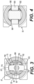
Figure 4 is a view of a bearing assembly configured to oppose twist relative to the outer body. -
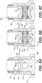
Figures 5-7 are views of an alternative lifter assembly and alternative pin assembly. -
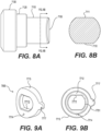
Figures 8A & 8B are views of a pin. -
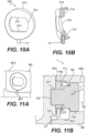
Figures 9A & 9B are views of an alternative bushing. -
Figures 10A & 10B are views of another alternative bushing. -
Figures 11A & 11B are views of an alternative lifter assembly with an alternative pin assembly. - Reference will now be made in detail to the examples which are illustrated in the accompanying drawings. Wherever possible, the same reference numbers will be used throughout the drawings to refer to the same or like parts. Directional references such as "left" and "right" are for ease of reference to the figures.
- A
lifter assembly cams 7 of the cam rail. Acam 7 is shown generally inFigures 1A & 1B . Lobes 31-33 impart lift profiles to the lifter assembly 1-3. If the lifter assembly, is latched (Figures 7 &11 ; Right-hand ofFigure 1B ; & bottom ofFigure 3 ), a first lift profile is imparted to one or more valves via the connection of push rod 4 to the valvetrain. If the lifter assembly is unlatched (Figures 6B & 6C ; Left-hand ofFigure 1B and top ofFigure 3 ), a different lift profile is imparted to the one or more valves. Such variable valvetrain (WA) techniques as engine braking (EB), cylinder deactivation (CDA), Late or Early valve closing or opening (LlVC, EIVC, LlVO, LEVO, EIVC, EIVO, EIVO, EEVO), and lost motions can be accomplished. In this disclosure, thelatch pin assembly - A
lifter assembly outer body oil port latch ports opposed latch ports inner body 6 rotate inside theouter body 5. Inlifter assembly opposed latch ports recess 5700 carved or tooled or cast in an inner diameter of theouter body 5000. In thelifter assembly 2, theinner body 6000 can rotate within theouter body 5000 because the latch ports in therecess 5700 can accommodate the rotation. - An
inner body roller assembly 63 ortappet 6300 configured to lift and lower to follow the lobes 31-33 ofcam 7. Theinner body pin passage pin assembly pin passage pin assembly bushing bushing lifter assembly steps outer surface bushing steps inner body inner body 6000 oflifter assembly 2 can comprise an additional anti-rotation step in addition to thestep 66710 so that thebushing 7500 can comprise ananti-rotation notch 7717 to press to the stepped inner body. - The
bushing pins lifter assembly oil supply 20 or gallery to outerbody oil port body oil passages pins bushing pin port pin rim narrow end pin port lip 712, 7120 can also function as a travel stop to limit how far the pin can slide through the pin port. Thepin port 751 can be formed in anend wall 750 of thebushing pin port bushing - The
pin port narrow end narrow end 710 is cylindrical but for a flat 711 that slides against a corresponding flat inend wall 750. Or, twoflats narrow end 7100. These twoflats corresponding flats pin port bushing latch ports - In the
pin assembly 70, thebushing bore 753 in a tubular structure configured so that therim 713 is guided within thebore 753 and is limited by the step. The step can be a part of theend wall 750 and the step can be comprised of theend wall 750 or a formation on the end wall. Thebushing bias spring end wall 750 or thebushing bias spring spring rim end wall 750 orspring rim lip 712, 7120 with an abutment torim bushing spring rim end wall 750, and wherein the pin assembly further comprises a spring biased against the spring seating area and therim - This configures the
pins pin assembly pins latch ports inner body 6 with a stop pin bore 693 intersecting thepin passage 67. Astop pin 93 can be placed in the stop pin bore 693 to limit the travel of thepins oil port 52 of theouter body 5, it is configured to fluidly communicate with anoil passage 621 in theinner body 6. The bushing can be configured with anoil slot 721 to fluidly communicate with theoil passage 621 to receive the pressurized fluid. Then, thepin 72 can be pushed to overcome thebias spring 74 to latch in thelatch port 572. But without pressurized fluid, thebias spring 73 pushes thepin 71 out of thelatch port 571 and into theinner body 6 so that the inner body can reciprocate within theouter body 5 according to the cam lobe profiles. To prevent thebias spring 73 from overcoming thebias spring 74, or vice versa, thestop pin 93 can be inserted. Then therims pins pin slots 793 can be formed in thebushings stop pin 93. This can provide an anti-rotation feature to thebushings - An additional anti-rotation feature can be provided to the
bushings anti-rotation groove 791, 792 can be formed in an external diameter of thebushing inner body 6 to intersect thepin passage 67.Anti-rotation rods anti-rotation grooves 791, 792 and the rod bores 691, 692 to prevent the bushings from rotating and altering the position of theflats 711 on thepins flats 711 can be assured. - In additional aspects, pin support and anti-rotation of the
pins Figures 6A-7 &11B therim inner body 6700. Pressurized fluid can be supplied tooil passage 6210 to push thepins Figures 7 &11B . To return from the latched position to the unlatched position ofFigures 6B & 6C , it can be beneficial to include anoil drain slot 66711 as a fluid leak-down path in addition to thestep 66710. Bushing 77500 can comprise ananti-rotation stake 1177 pressed in the bushing and pressed into thedrain slot 66711. Fluid pressure can be relieved while securing an anti-rotation function. The bias springs 7300, 7400 can assist with pushing the pressurized fluid out of thedrain slot 66711 to return to the unlatched position. - Alternatively, the
bushing oil drain - In yet another alternative, in the lifter assembly 1, the
inner body 6 comprises aslot bushing recess 7511. Thepin assembly 70 can then further comprise acorresponding stake slot recess 7511. Thestake inner body 6. Thestake stake slot - In another anti-rotation aspect, the lifter assembly 1 can comprise a follower anti-rotation bore 68 in the
inner body 6. The outer body can comprise afollower anti-rotation slot 581. Afollower anti-rotation rod 80 can be seated to extend out of the follower anti-rotation bore 68 into thefollower anti-rotation slot 581. The follower anti-rotation bore can pass through theinner body 6 and theouter body 5 can comprise a secondfollower anti-rotation slot 582. Theanti-rotation rod 80 can pass through theinner body 6 completely and extend out into both thefollower anti-rotation slot 581 and the secondfollower anti-rotation slot 582. Theanti-rotation rod 80 can assist with preventing the twisting of the bearingassembly 63 relative to thecam 7. Theanti-rotation rod 80 can also provide a travel limit for restricting the motion of theinner body 6 relative to theouter body 5 as theanti-rotation rod 80 engages with thefollower anti-rotation slot 581 and the secondfollower anti-rotation slot 582. - In an additional aspect, the bearing
assembly 63 can be configured to prevent its twisting against thecam 7 by way of thebearing 633 bracing against thefollower anti-rotation slot 581 and the secondfollower anti-rotation slot 582. Bearing 633 can rotate on anaxle 632 supported inports 631 of axle arms associated with theinner body 6. It is possible to form guide grooves on inner surfaces oftappet arms outer body 5. Theaxle 632 and bearing 633 can be guided against twisting relative to theouter body 5 thereby.Tappet arms lobes cam 7. - The latched or unlatched position of the
latch assembly inner body rod seat bias assembly cam 7. - While the disclosure has shown a lifter assembly, other hydromechanical latching mechanisms can benefit from the
latch pin assemblies - Other implementations will be apparent to those skilled in the art from consideration of the specification and practice of the examples disclosed herein.
Claims (14)
- A lifter assembly (1; 2; 7), comprising:an outer body (5; 5000), comprising an oil port (52; 5200) and opposed latch ports (571, 572; 5710, 5720);an inner body (6; 6000; 6001) comprising a roller assembly (63) or tappet (6300) configured to lift and lower to follow a cam (3), the inner body further comprising an oil passage (621; 6210, 6220) fluidly communicating with a pin passage (67; 6700) comprising an inner diameter; anda pin assembly (70; 7000; 7001) mounted in the pin passage (67; 6700), the pin assembly comprising for each of the opposed latch ports:a bushing (75, 76; 7500, 7600; 77500) abutting the inner diameter, the bushing comprising a pin port (751; 7751; 77751); anda pin (71, 72; 7100, 7200) comprising a rim (713, 714; 7130, 7240) and a narrow end (710; 7100) configured for sliding in the pin port (751; 7751; 77751);characterized in that the pin port (751; 7751; 77751) and the narrow end (710; 7100) are keyed in an anti-rotation configuration.
- The lifter assembly of claim 1, wherein the inner diameter is stepped and the bushing is pressed (75, 76; 7500, 7600; 77500) to the stepped inner diameter.
- The lifter assembly of claim 2, wherein the rim (7130, 7240) slides against the inner diameter.
- The lifter assembly of claim 1, wherein the inner body comprises a slot (611, 612), and wherein the bushing (75, 76) comprises a recess (7511), and wherein the pin assembly (70) further comprises a stake (11, 12) spanning a portion of the slot and into the recess.
- The lifter assembly of any one of claims 1-4, wherein the bushing (75, 76; 7500, 7600; 77500) further comprises a fluid leak-down path.
- The lifter assembly of claim 4, wherein the stake (11, 12) comprises a fluid leak-down path.
- The lifter assembly of claim 1, wherein the bushing (71, 72) comprises a step and a bore (753) in a tubular structure configured so that the rim (713) is guided within the bore and is limited by the step.
- The lifter assembly of claim 7, wherein the bushing (75, 76; 7500; 77500) comprises an end wall (750) comprising the pin port (751), wherein the end wall comprises a spring seating area, and wherein the pin assembly further comprises a spring (7300, 7400) biased against the spring seating area and the rim (713, 714; 7130, 7240).
- The lifter assembly of claim 7, further comprising an anti-rotation groove (791, 792) in an external diameter of the bushing (75, 76); a rod bore (691, 692) through the inner body (6) and intersecting the pin passage (67); and an anti-rotation rod (91, 92) seated in the anti-rotation groove and in the rod bore.
- The lifter assembly of claim 1, wherein the inner body further comprises a stop pin bore (693) intersecting the pin passage (67), and wherein the lifter assembly (1) further comprises a stop pin (93) in the stop pin bore, the stop pin configured to limit the travel of the pin.
- The lifter assembly of claim 1, wherein the inner body further comprises a follower anti-rotation bore (68), wherein the outer body further comprises a follower anti-rotation slot (581), and wherein the lifter assembly further comprises a follower anti-rotation rod (80) seated to extend out of the follower anti-rotation bore into the follower anti-rotation slot.
- The lifter assembly of claim 11, wherein the follower anti-rotation bore (68) passes through the inner body (6), wherein the outer body (5) comprises a second follower anti-rotation slot (582), and wherein the anti-rotation rod (80) passes through the inner body completely and extends out into the second follower anti-rotation slot.
- The lifter assembly of claim 1, wherein the bushing is configured with an oil slot (721) to fluidly communicate with the oil passage (621).
- The lifter assembly of claim 1, wherein the pin assembly (70, 7000, 7001) is biased so that the pins (71, 72, 7100) are retracted away from the latch ports (571, 572, 5710, 5720).
Applications Claiming Priority (2)
| Application Number | Priority Date | Filing Date | Title |
|---|---|---|---|
| IN201911042844 | 2019-10-22 | ||
| PCT/EP2020/025471 WO2021078413A1 (en) | 2019-10-22 | 2020-10-22 | Lifter assembly |
Publications (2)
| Publication Number | Publication Date |
|---|---|
| EP4048874A1 EP4048874A1 (en) | 2022-08-31 |
| EP4048874B1 true EP4048874B1 (en) | 2024-11-27 |
Family
ID=73138790
Family Applications (1)
| Application Number | Title | Priority Date | Filing Date |
|---|---|---|---|
| EP20803089.0A Active EP4048874B1 (en) | 2019-10-22 | 2020-10-22 | Lifter assembly |
Country Status (4)
| Country | Link |
|---|---|
| US (1) | US12392264B2 (en) |
| EP (1) | EP4048874B1 (en) |
| CN (1) | CN114450468A (en) |
| WO (1) | WO2021078413A1 (en) |
Family Cites Families (15)
| Publication number | Priority date | Publication date | Assignee | Title |
|---|---|---|---|---|
| US1500556A (en) * | 1919-03-05 | 1924-07-08 | William M Goodwin | Valve-operating means for internal-combustion engines |
| US6076491A (en) * | 1994-05-03 | 2000-06-20 | Lotus Cars Limited | Valve control mechanism |
| US5673661A (en) * | 1995-11-27 | 1997-10-07 | Jesel; Daniel Henry | Valve lifter |
| DE19608651A1 (en) | 1996-03-06 | 1997-09-11 | Schaeffler Waelzlager Kg | Valve train for gas exchange valves of internal combustion engines |
| DE19742777A1 (en) * | 1997-09-27 | 1999-04-01 | Schaeffler Waelzlager Ohg | Tappet for a valve train of an internal combustion engine |
| US6513470B1 (en) | 2000-10-20 | 2003-02-04 | Delphi Technologies, Inc. | Deactivation hydraulic valve lifter |
| DE10120448A1 (en) * | 2001-04-26 | 2002-10-31 | Ina Schaeffler Kg | Device for smoothing of irregular drive moment of especially camshaft of internal combustion engine has facility whereby force of cam follower system is variable dependent upon RPM |
| DE10135175A1 (en) * | 2001-07-19 | 2003-02-06 | Ina Schaeffler Kg | Switchable bucket tappet |
| DE102006034624A1 (en) | 2006-07-27 | 2008-01-31 | Bayerische Motoren Werke Ag | Internal-combustion engine`s valve drive, has pressure unit provided at closing unit through opening, and stop provided at pressure unit as path limitation for pressure unit during movement in direction of cam |
| DE102008031295A1 (en) | 2007-07-20 | 2009-01-22 | Schaeffler Kg | Switchable bucket tappets for a valve train of an internal combustion engine |
| EP2653674A1 (en) | 2012-04-19 | 2013-10-23 | Eaton S.r.l. | Hydraulic lash adjuster |
| US20150101562A1 (en) * | 2013-10-16 | 2015-04-16 | Kia Motors Corporation | Cda device |
| US10927723B2 (en) | 2017-07-03 | 2021-02-23 | Eaton Intelligent Power Limited | Engine valve lifter assemblies |
| WO2019149454A1 (en) | 2018-01-31 | 2019-08-08 | Eaton Intelligent Power Limited | Two-part lifter assembly |
| DE202020105299U1 (en) | 2019-09-16 | 2020-11-24 | Eaton Intelligent Power Limited | Locking pin for use in a valve lifter and valve lifter containing the same |
-
2020
- 2020-10-22 WO PCT/EP2020/025471 patent/WO2021078413A1/en not_active Ceased
- 2020-10-22 US US17/771,319 patent/US12392264B2/en active Active
- 2020-10-22 EP EP20803089.0A patent/EP4048874B1/en active Active
- 2020-10-22 CN CN202080067993.8A patent/CN114450468A/en active Pending
Also Published As
| Publication number | Publication date |
|---|---|
| WO2021078413A1 (en) | 2021-04-29 |
| US12392264B2 (en) | 2025-08-19 |
| EP4048874A1 (en) | 2022-08-31 |
| US20220349321A1 (en) | 2022-11-03 |
| CN114450468A (en) | 2022-05-06 |
Similar Documents
| Publication | Publication Date | Title |
|---|---|---|
| EP2094949B1 (en) | Dual lift rocker arm latch mechanism andactuation arrangement therefor | |
| US5709180A (en) | Narrow cam two-step lifter | |
| US5090364A (en) | Two-step valve operating mechanism | |
| US7546822B2 (en) | Switching finger follower assembly | |
| US20180045081A1 (en) | Switching rocker arm assembly having eccentric axle for lash adjustment | |
| US12188382B2 (en) | Rocker arms | |
| EP3620624B1 (en) | Switchable rocker arm and roller retainer thereof | |
| EP3959424B1 (en) | Deactivating rocker arm and capsules | |
| US20090078225A1 (en) | Switchable rocker arm | |
| US11208921B2 (en) | Finger follower for lobe switching and single source lost motion | |
| US10968788B2 (en) | Two-part lifter assembly | |
| CN116635610A (en) | Sheet metal stamped rocker assembly with latch pin assembly | |
| CN110869588A (en) | engine valve lifter | |
| US12392264B2 (en) | Lifter assembly | |
| JP7302018B2 (en) | Switched Lobe and Single Source Lost Motion Finger Followers | |
| CN105673121A (en) | Variable valve lift apparatus | |
| EP3911846B1 (en) | Selective resetting lost motion engine valve train components | |
| US11828205B2 (en) | Latch assembly and compact rocker arm assembly | |
| EP3452703B1 (en) | Anti-rotation feature for followers using an oil gallery insert | |
| GB2427897A (en) | I.c. engine camshaft with fixed and slideable cams switchable between high-lift and low-lift modes |
Legal Events
| Date | Code | Title | Description |
|---|---|---|---|
| STAA | Information on the status of an ep patent application or granted ep patent |
Free format text: STATUS: UNKNOWN |
|
| STAA | Information on the status of an ep patent application or granted ep patent |
Free format text: STATUS: THE INTERNATIONAL PUBLICATION HAS BEEN MADE |
|
| PUAI | Public reference made under article 153(3) epc to a published international application that has entered the european phase |
Free format text: ORIGINAL CODE: 0009012 |
|
| STAA | Information on the status of an ep patent application or granted ep patent |
Free format text: STATUS: REQUEST FOR EXAMINATION WAS MADE |
|
| 17P | Request for examination filed |
Effective date: 20220503 |
|
| AK | Designated contracting states |
Kind code of ref document: A1 Designated state(s): AL AT BE BG CH CY CZ DE DK EE ES FI FR GB GR HR HU IE IS IT LI LT LU LV MC MK MT NL NO PL PT RO RS SE SI SK SM TR |
|
| DAV | Request for validation of the european patent (deleted) | ||
| DAX | Request for extension of the european patent (deleted) | ||
| P01 | Opt-out of the competence of the unified patent court (upc) registered |
Effective date: 20230521 |
|
| GRAP | Despatch of communication of intention to grant a patent |
Free format text: ORIGINAL CODE: EPIDOSNIGR1 |
|
| STAA | Information on the status of an ep patent application or granted ep patent |
Free format text: STATUS: GRANT OF PATENT IS INTENDED |
|
| RIC1 | Information provided on ipc code assigned before grant |
Ipc: F01L 13/06 20060101ALN20240307BHEP Ipc: F01L 1/46 20060101ALI20240307BHEP Ipc: F01L 13/00 20060101ALI20240307BHEP Ipc: F01L 1/14 20060101AFI20240307BHEP |
|
| RIC1 | Information provided on ipc code assigned before grant |
Ipc: F01L 13/06 20060101ALN20240315BHEP Ipc: F01L 1/46 20060101ALI20240315BHEP Ipc: F01L 13/00 20060101ALI20240315BHEP Ipc: F01L 1/14 20060101AFI20240315BHEP |
|
| INTG | Intention to grant announced |
Effective date: 20240404 |
|
| GRAJ | Information related to disapproval of communication of intention to grant by the applicant or resumption of examination proceedings by the epo deleted |
Free format text: ORIGINAL CODE: EPIDOSDIGR1 |
|
| STAA | Information on the status of an ep patent application or granted ep patent |
Free format text: STATUS: REQUEST FOR EXAMINATION WAS MADE |
|
| GRAP | Despatch of communication of intention to grant a patent |
Free format text: ORIGINAL CODE: EPIDOSNIGR1 |
|
| INTC | Intention to grant announced (deleted) | ||
| STAA | Information on the status of an ep patent application or granted ep patent |
Free format text: STATUS: GRANT OF PATENT IS INTENDED |
|
| RIC1 | Information provided on ipc code assigned before grant |
Ipc: F01L 13/06 20060101ALN20240531BHEP Ipc: F01L 1/46 20060101ALI20240531BHEP Ipc: F01L 13/00 20060101ALI20240531BHEP Ipc: F01L 1/14 20060101AFI20240531BHEP |
|
| INTG | Intention to grant announced |
Effective date: 20240620 |
|
| GRAS | Grant fee paid |
Free format text: ORIGINAL CODE: EPIDOSNIGR3 |
|
| GRAA | (expected) grant |
Free format text: ORIGINAL CODE: 0009210 |
|
| STAA | Information on the status of an ep patent application or granted ep patent |
Free format text: STATUS: THE PATENT HAS BEEN GRANTED |
|
| AK | Designated contracting states |
Kind code of ref document: B1 Designated state(s): AL AT BE BG CH CY CZ DE DK EE ES FI FR GB GR HR HU IE IS IT LI LT LU LV MC MK MT NL NO PL PT RO RS SE SI SK SM TR |
|
| REG | Reference to a national code |
Ref country code: GB Ref legal event code: FG4D |
|
| REG | Reference to a national code |
Ref country code: CH Ref legal event code: EP |
|
| REG | Reference to a national code |
Ref country code: IE Ref legal event code: FG4D |
|
| REG | Reference to a national code |
Ref country code: DE Ref legal event code: R096 Ref document number: 602020042155 Country of ref document: DE |
|
| REG | Reference to a national code |
Ref country code: LT Ref legal event code: MG9D |
|
| REG | Reference to a national code |
Ref country code: NL Ref legal event code: MP Effective date: 20241127 |
|
| PG25 | Lapsed in a contracting state [announced via postgrant information from national office to epo] |
Ref country code: HR Free format text: LAPSE BECAUSE OF FAILURE TO SUBMIT A TRANSLATION OF THE DESCRIPTION OR TO PAY THE FEE WITHIN THE PRESCRIBED TIME-LIMIT Effective date: 20241127 Ref country code: PT Free format text: LAPSE BECAUSE OF FAILURE TO SUBMIT A TRANSLATION OF THE DESCRIPTION OR TO PAY THE FEE WITHIN THE PRESCRIBED TIME-LIMIT Effective date: 20250327 Ref country code: IS Free format text: LAPSE BECAUSE OF FAILURE TO SUBMIT A TRANSLATION OF THE DESCRIPTION OR TO PAY THE FEE WITHIN THE PRESCRIBED TIME-LIMIT Effective date: 20250327 |
|
| PG25 | Lapsed in a contracting state [announced via postgrant information from national office to epo] |
Ref country code: FI Free format text: LAPSE BECAUSE OF FAILURE TO SUBMIT A TRANSLATION OF THE DESCRIPTION OR TO PAY THE FEE WITHIN THE PRESCRIBED TIME-LIMIT Effective date: 20241127 Ref country code: NL Free format text: LAPSE BECAUSE OF FAILURE TO SUBMIT A TRANSLATION OF THE DESCRIPTION OR TO PAY THE FEE WITHIN THE PRESCRIBED TIME-LIMIT Effective date: 20241127 |
|
| REG | Reference to a national code |
Ref country code: AT Ref legal event code: MK05 Ref document number: 1745897 Country of ref document: AT Kind code of ref document: T Effective date: 20241127 |
|
| PG25 | Lapsed in a contracting state [announced via postgrant information from national office to epo] |
Ref country code: BG Free format text: LAPSE BECAUSE OF FAILURE TO SUBMIT A TRANSLATION OF THE DESCRIPTION OR TO PAY THE FEE WITHIN THE PRESCRIBED TIME-LIMIT Effective date: 20241127 |
|
| PG25 | Lapsed in a contracting state [announced via postgrant information from national office to epo] |
Ref country code: ES Free format text: LAPSE BECAUSE OF FAILURE TO SUBMIT A TRANSLATION OF THE DESCRIPTION OR TO PAY THE FEE WITHIN THE PRESCRIBED TIME-LIMIT Effective date: 20241127 |
|
| PG25 | Lapsed in a contracting state [announced via postgrant information from national office to epo] |
Ref country code: NO Free format text: LAPSE BECAUSE OF FAILURE TO SUBMIT A TRANSLATION OF THE DESCRIPTION OR TO PAY THE FEE WITHIN THE PRESCRIBED TIME-LIMIT Effective date: 20250227 |
|
| PG25 | Lapsed in a contracting state [announced via postgrant information from national office to epo] |
Ref country code: LV Free format text: LAPSE BECAUSE OF FAILURE TO SUBMIT A TRANSLATION OF THE DESCRIPTION OR TO PAY THE FEE WITHIN THE PRESCRIBED TIME-LIMIT Effective date: 20241127 Ref country code: AT Free format text: LAPSE BECAUSE OF FAILURE TO SUBMIT A TRANSLATION OF THE DESCRIPTION OR TO PAY THE FEE WITHIN THE PRESCRIBED TIME-LIMIT Effective date: 20241127 Ref country code: GR Free format text: LAPSE BECAUSE OF FAILURE TO SUBMIT A TRANSLATION OF THE DESCRIPTION OR TO PAY THE FEE WITHIN THE PRESCRIBED TIME-LIMIT Effective date: 20250228 |
|
| PG25 | Lapsed in a contracting state [announced via postgrant information from national office to epo] |
Ref country code: PL Free format text: LAPSE BECAUSE OF FAILURE TO SUBMIT A TRANSLATION OF THE DESCRIPTION OR TO PAY THE FEE WITHIN THE PRESCRIBED TIME-LIMIT Effective date: 20241127 |
|
| PG25 | Lapsed in a contracting state [announced via postgrant information from national office to epo] |
Ref country code: RS Free format text: LAPSE BECAUSE OF FAILURE TO SUBMIT A TRANSLATION OF THE DESCRIPTION OR TO PAY THE FEE WITHIN THE PRESCRIBED TIME-LIMIT Effective date: 20250227 |
|
| PG25 | Lapsed in a contracting state [announced via postgrant information from national office to epo] |
Ref country code: SM Free format text: LAPSE BECAUSE OF FAILURE TO SUBMIT A TRANSLATION OF THE DESCRIPTION OR TO PAY THE FEE WITHIN THE PRESCRIBED TIME-LIMIT Effective date: 20241127 |
|
| PG25 | Lapsed in a contracting state [announced via postgrant information from national office to epo] |
Ref country code: DK Free format text: LAPSE BECAUSE OF FAILURE TO SUBMIT A TRANSLATION OF THE DESCRIPTION OR TO PAY THE FEE WITHIN THE PRESCRIBED TIME-LIMIT Effective date: 20241127 |
|
| PG25 | Lapsed in a contracting state [announced via postgrant information from national office to epo] |
Ref country code: EE Free format text: LAPSE BECAUSE OF FAILURE TO SUBMIT A TRANSLATION OF THE DESCRIPTION OR TO PAY THE FEE WITHIN THE PRESCRIBED TIME-LIMIT Effective date: 20241127 |
|
| PG25 | Lapsed in a contracting state [announced via postgrant information from national office to epo] |
Ref country code: RO Free format text: LAPSE BECAUSE OF FAILURE TO SUBMIT A TRANSLATION OF THE DESCRIPTION OR TO PAY THE FEE WITHIN THE PRESCRIBED TIME-LIMIT Effective date: 20241127 |
|
| PG25 | Lapsed in a contracting state [announced via postgrant information from national office to epo] |
Ref country code: SK Free format text: LAPSE BECAUSE OF FAILURE TO SUBMIT A TRANSLATION OF THE DESCRIPTION OR TO PAY THE FEE WITHIN THE PRESCRIBED TIME-LIMIT Effective date: 20241127 |
|
| PG25 | Lapsed in a contracting state [announced via postgrant information from national office to epo] |
Ref country code: CZ Free format text: LAPSE BECAUSE OF FAILURE TO SUBMIT A TRANSLATION OF THE DESCRIPTION OR TO PAY THE FEE WITHIN THE PRESCRIBED TIME-LIMIT Effective date: 20241127 |
|
| PG25 | Lapsed in a contracting state [announced via postgrant information from national office to epo] |
Ref country code: IT Free format text: LAPSE BECAUSE OF FAILURE TO SUBMIT A TRANSLATION OF THE DESCRIPTION OR TO PAY THE FEE WITHIN THE PRESCRIBED TIME-LIMIT Effective date: 20241127 |
|
| REG | Reference to a national code |
Ref country code: DE Ref legal event code: R097 Ref document number: 602020042155 Country of ref document: DE |
|
| PG25 | Lapsed in a contracting state [announced via postgrant information from national office to epo] |
Ref country code: SE Free format text: LAPSE BECAUSE OF FAILURE TO SUBMIT A TRANSLATION OF THE DESCRIPTION OR TO PAY THE FEE WITHIN THE PRESCRIBED TIME-LIMIT Effective date: 20241127 |
|
| PLBE | No opposition filed within time limit |
Free format text: ORIGINAL CODE: 0009261 |
|
| STAA | Information on the status of an ep patent application or granted ep patent |
Free format text: STATUS: NO OPPOSITION FILED WITHIN TIME LIMIT |
|
| 26N | No opposition filed |
Effective date: 20250828 |
|
| PGFP | Annual fee paid to national office [announced via postgrant information from national office to epo] |
Ref country code: DE Payment date: 20250923 Year of fee payment: 6 |