EP4048047B1 - Improved trolley unit, in particular for a reversible ploughing system, and reversible ploughing system comprising such trolley unit - Google Patents
Improved trolley unit, in particular for a reversible ploughing system, and reversible ploughing system comprising such trolley unit Download PDFInfo
- Publication number
- EP4048047B1 EP4048047B1 EP20765102.7A EP20765102A EP4048047B1 EP 4048047 B1 EP4048047 B1 EP 4048047B1 EP 20765102 A EP20765102 A EP 20765102A EP 4048047 B1 EP4048047 B1 EP 4048047B1
- Authority
- EP
- European Patent Office
- Prior art keywords
- trolley unit
- wheels
- operating
- ploughing
- handling device
- Prior art date
- Legal status (The legal status is an assumption and is not a legal conclusion. Google has not performed a legal analysis and makes no representation as to the accuracy of the status listed.)
- Active
Links
Images


Classifications
-
- A—HUMAN NECESSITIES
- A01—AGRICULTURE; FORESTRY; ANIMAL HUSBANDRY; HUNTING; TRAPPING; FISHING
- A01B—SOIL WORKING IN AGRICULTURE OR FORESTRY; PARTS, DETAILS, OR ACCESSORIES OF AGRICULTURAL MACHINES OR IMPLEMENTS, IN GENERAL
- A01B3/00—Ploughs with fixed plough-shares
- A01B3/46—Ploughs supported partly by tractor and partly by their own wheels
- A01B3/464—Alternating ploughs with frame rotating about a horizontal axis, e.g. turn-wrest ploughs
-
- A—HUMAN NECESSITIES
- A01—AGRICULTURE; FORESTRY; ANIMAL HUSBANDRY; HUNTING; TRAPPING; FISHING
- A01B—SOIL WORKING IN AGRICULTURE OR FORESTRY; PARTS, DETAILS, OR ACCESSORIES OF AGRICULTURAL MACHINES OR IMPLEMENTS, IN GENERAL
- A01B63/00—Lifting or adjusting devices or arrangements for agricultural machines or implements
- A01B63/14—Lifting or adjusting devices or arrangements for agricultural machines or implements for implements drawn by animals or tractors
- A01B63/16—Lifting or adjusting devices or arrangements for agricultural machines or implements for implements drawn by animals or tractors with wheels adjustable relatively to the frame
- A01B63/22—Lifting or adjusting devices or arrangements for agricultural machines or implements for implements drawn by animals or tractors with wheels adjustable relatively to the frame operated by hydraulic or pneumatic means
-
- A—HUMAN NECESSITIES
- A01—AGRICULTURE; FORESTRY; ANIMAL HUSBANDRY; HUNTING; TRAPPING; FISHING
- A01B—SOIL WORKING IN AGRICULTURE OR FORESTRY; PARTS, DETAILS, OR ACCESSORIES OF AGRICULTURAL MACHINES OR IMPLEMENTS, IN GENERAL
- A01B73/00—Means or arrangements to facilitate transportation of agricultural machines or implements, e.g. folding frames to reduce overall width
-
- B—PERFORMING OPERATIONS; TRANSPORTING
- B60—VEHICLES IN GENERAL
- B60B—VEHICLE WHEELS; CASTORS; AXLES FOR WHEELS OR CASTORS; INCREASING WHEEL ADHESION
- B60B35/00—Axle units; Parts thereof ; Arrangements for lubrication of axles
- B60B35/003—Steerable axles
-
- B—PERFORMING OPERATIONS; TRANSPORTING
- B60—VEHICLES IN GENERAL
- B60B—VEHICLE WHEELS; CASTORS; AXLES FOR WHEELS OR CASTORS; INCREASING WHEEL ADHESION
- B60B35/00—Axle units; Parts thereof ; Arrangements for lubrication of axles
- B60B35/009—Axle units; Parts thereof ; Arrangements for lubrication of axles adapted for tiltable wheels
-
- B—PERFORMING OPERATIONS; TRANSPORTING
- B60—VEHICLES IN GENERAL
- B60B—VEHICLE WHEELS; CASTORS; AXLES FOR WHEELS OR CASTORS; INCREASING WHEEL ADHESION
- B60B35/00—Axle units; Parts thereof ; Arrangements for lubrication of axles
- B60B35/02—Dead axles, i.e. not transmitting torque
- B60B35/10—Dead axles, i.e. not transmitting torque adjustable for varying track
-
- B—PERFORMING OPERATIONS; TRANSPORTING
- B60—VEHICLES IN GENERAL
- B60Y—INDEXING SCHEME RELATING TO ASPECTS CROSS-CUTTING VEHICLE TECHNOLOGY
- B60Y2200/00—Type of vehicle
- B60Y2200/20—Off-Road Vehicles
- B60Y2200/22—Agricultural vehicles
Definitions
- the present invention refers to an improved trolley unit, of the type with abutment of the wheels with double function for circulating and working, in particular for a reversible ploughing system and to a reversible ploughing system comprising such trolley unit.
- ploughing systems are known in the art, with trolley units or wheel-type supporting systems used to handle and transport such systems to their working sites.
- ploughing systems are known, such as for example the one disclosed in EP1099363 of the same Applicant, equipped with a trolley unit which allows the reversible ploughing system to pass from a circulation position to a working position and vice versa: in particular, these known trolley units comprise two hydraulic jacks which perform the function of rotating-translating the wheel hub to make the wheel assume a correct orientation and position for the two phases (working and circulating), and the ploughing depth, depending on the position of the wheels when working, is regulated through a mechanical screwtype limit switch, which limits the translation of the hubs along the main beam of the trolley unit. Consequently, each jack only operates on the movement of its related wheel, without playing any role in the regulation of the working depth.
- Trolley units are also known for reversible ploughing systems, which comprise an hydraulic jack aimed to regulate the ploughing depth: in such units, the rotation of the wheel hubs from the circulating position to the working position, and vice versa, must be performed manually, consequently resulting scarcely practical and easy, or through two further dedicated hydraulic jacks, therefore implying a greater complexity of the hydraulic plant, and the need of a further hydraulic actuation of the transporting and working means, such as for example a common agricultural tractor, to which the ploughing system is connected.
- object of the present invention is solving the above prior art problems, by providing an improved trolley unit, in particular for a reversible ploughing system, comprising a single actuating system which allows both to pass the wheels from a circulating position to a working position and vice versa, and to make such trolley unit assume an operating working configuration chosen among a plurality of possible operating working configurations, for example in order to allow regulating the ploughing depth, performed by the reversible ploughing system to which such trolley unit is connected, consequently having a more practical and easier use, however structurally less complex with respect to what is proposed by the prior art.
- a further object of the present invention is providing a reversible ploughing system comprising at least one trolley unit comprising a single actuating system which allows both to pass the wheels from a circulating position to a working position and vice versa, and to make such trolley unit assume an operating working configuration chosen among a plurality of possible operating working configurations, for example in order to allow regulating the ploughing depth, performed by the reversible ploughing system to which such trolley unit is connected, consequently having a more practical and easier use, however structurally less complex with respect to what is proposed by the prior art.
- the trolley unit 1 comprises at least two wheels 3, an actuating system 2 and at least one transmission system 17, such actuating system 2 operatively cooperating with such transmission system 17 both for passing such wheels 3 from an operating circulating position to an operating working position, and vice versa, and for changing an operating working configuration of such trolley unit 1, preferably modifying the distance between the wheels 3 (for example at least when the wheels 3 are in their operating working position).
- the trolley unit 1 then comprises:
- the transmission system 17 comprises at least one articulated kinematism 14 composed of at least one second variable length handling device 26, preferably a second hydraulic jack supplied by a suitable tank 27 containing an hydraulic fluid, common to a pair of articulated transmissions, each of which related to a respective hub 5, each of the articulated transmissions comprising:
- the actuating system 2 comprises, preferably, at least one first variable length handling device 19, for example of the type with hydraulic jack, mutually operatively connecting the drive shafts 9 in respective articulation points 21 and adjustable in length depending on the operating position of the wheels 3 and/or on the operating working configuration of the trolley unit 1 which has to be obtained.
- variable-length handling device can have its respective ends connected articulated to a respective drive shaft 9, preferably next to each first end of these latter ones in the respective articulation points 21.
- the first variable length handling device 19 will then have a first running position adapted to move, through the cooperation of the transmission system 18, the wheels 3 from their operating circulating position to their operating working position, and vice versa, by acting on the respective articulating kinematism 11; the variable-length handling device 19 will then have a second running portion adapted to take the trolley unit 1 according to the present invention to various operating working configurations.
- Figure 3 shows the trolley unit 1 in which the wheels 3 are in their operating circulating position, having their rotation axes around their respective, substantially coinciding hubs.
- the coupling variable-length handling device 19 along its own first running position decreases the subtended angle between the drive shafts 9 and, through the articulated kinematism 18 of the transmission system 17, the progressive divergence of the wheels 3, and of their respective rotation axes, till the wheels 3 are taken to their operating working position, as shown in Figure 5 (in which, preferably, the rotation axes of the wheels 3 are substantially mutually parallel) passing through the intermediate operating position of the wheels 3 shown in Figure 4 .
- the contrary movement of the variable-length handling device 19, namely its elongation along its own first running position allows, in cooperation with the articulated kinematism 18 of the transmission system 17, the reverse passage, namely the passage of the wheels 3 from their operating working position to their operating circulating position.
- the actuating system 2, and in particular the variable-length handling device 19, is further adapted to change the distance between the wheels 3, for example at least when they are in their operating working position, to make trolley unit 1 according to the present invention assume various operating working configurations, each of such configurations being determined by the distance set between such wheels by such variable-length handling device 19, in particular by changing the subtended angle between the drive shafts 9.
- Figure 5 shows the trolley unit 1 in which the wheels 3 are at their maximum mutual distance allowed by the shape of the actuating system 2 and of the transmission system 17: in particular, in such operating configuration, the variable-length handling device 19 is in a position of maximum extension along its own second running portion.
- Figure 6 instead shows the trolley unit 1 in which the wheels 3 are at their minimum mutual distance allowed by the shape of the second actuating system 2 and of the transmission system 17: in particular, in such operating configuration, the variable-length handling device 19 is in a position of minimum extension along its own second running portion.
- trolley unit 1 can assume any further operating working configuration included between the two limit operating configurations shown in Figures 5 and 6 depending on the distance between the wheels 3, and in particular the subtended angle between the drive shafts 9, determined by the length assumed by the variable-length handling device 19 along its own second running portion.
- the second variable length handling device 26 coupled with the first variable length handling device 19 (which operates as accumulator or hydraulic spring) has the task of keeping the wheels 3 correctly oriented during the working phase (phase in which it works by thrusting two to the pressure of the first variable length handling device 19: this occurs for a good part of the excursion of the first variable length handling device 19 dedicated to regulating the ploughing depth.
- the working depth decreases, and also the second variable length handling device 26 is elongated, but continues keeping the wheels 3 in their working positions, until the second variable length handling device 26 reaches its maximum extension: it then ends its function of a spring and becomes a sort of tie-rod, further increasing the extension of the first variable length handling device 19 (which still has part of its working stroke available), while the traction on the leverages of the second variable length handling device 26 rotates the hubs, positioning the wheels 3 in their transport configuration.
- the present invention further refers to a reversible ploughing system comprising at least one trolley unit 1 as previously described.
- Such system substantially comprises a supporting frame 101 equipped wih a plurality of ploughing units 103.
- the ploughing units 103 being known in the art and not being part of the present invention, will not be further described in detail.
- the supporting frame 101 is adapted to be connected to transporting and working means, such as for example a common agricultural tractor (not shown) through an orientable fastening system (not shown) which makes it possible for the reversible ploughing system to assume two operating positions, namely the circulating position for transporting to the working place and the actual ploughing working position: also the fastening head, being known in the art and not being part of the present invention, will not be further described in detail.
- the reversible ploughing system 100 of the invention further comprises at least one trolley unit 1 like the previously described one, connected to the supporting frame 101, to innovatively allow it to be transported to its working place.
- the hydraulic jack possibly composing the variable-length handling device 19 of the trolley unit 1 can be advantageously connected to a suitable single connector available on the tractor to exploit the hydraulic plant and its related commands and leaving free further possible connectors for other applications, if necessary.
- the trolley unit 1 allows both changing the position and the orientation of the wheels 3 between an operating circulating position and an operating working position, and vice versa, and assuming one among different possible operating working configurations through a single actuating system 2 cooperating with the transmission system 17.
- Figure 7 shows the reversible ploughing system 100 according to the present invention with the trolley unit 1 in its operating working configuration (corresponding to the one shown in Figure 5 ) which allows a minimum ploughing depth
- Figure 8 shows the reversible ploughing system 100 according to the present invention with the trolley unit 1 in its operating working configuration (corresponding to the one shown in Figure 6 ) which allows a maximum ploughing depth.
- the ploughing system 100 according to the present invention can operate with different ploughing depths included among those shown above as an example, taking the trolley unit 1 according to the present invention to assume any further operating working configuration included between the two limit operating configurations shown in Figures 5 and 6 depending on the the distance between the wheels 3 determined by the handling device 19 and, in particular, by the length assumed by the variable-length handling device 19.
Landscapes
- Life Sciences & Earth Sciences (AREA)
- Engineering & Computer Science (AREA)
- Mechanical Engineering (AREA)
- Soil Sciences (AREA)
- Environmental Sciences (AREA)
- Zoology (AREA)
- Handcart (AREA)
- Soil Working Implements (AREA)
Description
- The present invention refers to an improved trolley unit, of the type with abutment of the wheels with double function for circulating and working, in particular for a reversible ploughing system and to a reversible ploughing system comprising such trolley unit.
- Various types of ploughing systems are known in the art, with trolley units or wheel-type supporting systems used to handle and transport such systems to their working sites.
- In particular, ploughing systems are known, such as for example the one disclosed in
EP1099363 of the same Applicant, equipped with a trolley unit which allows the reversible ploughing system to pass from a circulation position to a working position and vice versa: in particular, these known trolley units comprise two hydraulic jacks which perform the function of rotating-translating the wheel hub to make the wheel assume a correct orientation and position for the two phases (working and circulating), and the ploughing depth, depending on the position of the wheels when working, is regulated through a mechanical screwtype limit switch, which limits the translation of the hubs along the main beam of the trolley unit. Consequently, each jack only operates on the movement of its related wheel, without playing any role in the regulation of the working depth. - Trolley units are also known for reversible ploughing systems, which comprise an hydraulic jack aimed to regulate the ploughing depth: in such units, the rotation of the wheel hubs from the circulating position to the working position, and vice versa, must be performed manually, consequently resulting scarcely practical and easy, or through two further dedicated hydraulic jacks, therefore implying a greater complexity of the hydraulic plant, and the need of a further hydraulic actuation of the transporting and working means, such as for example a common agricultural tractor, to which the ploughing system is connected.
- Therefore, object of the present invention is solving the above prior art problems, by providing an improved trolley unit, in particular for a reversible ploughing system, comprising a single actuating system which allows both to pass the wheels from a circulating position to a working position and vice versa, and to make such trolley unit assume an operating working configuration chosen among a plurality of possible operating working configurations, for example in order to allow regulating the ploughing depth, performed by the reversible ploughing system to which such trolley unit is connected, consequently having a more practical and easier use, however structurally less complex with respect to what is proposed by the prior art.
- A further object of the present invention is providing a reversible ploughing system comprising at least one trolley unit comprising a single actuating system which allows both to pass the wheels from a circulating position to a working position and vice versa, and to make such trolley unit assume an operating working configuration chosen among a plurality of possible operating working configurations, for example in order to allow regulating the ploughing depth, performed by the reversible ploughing system to which such trolley unit is connected, consequently having a more practical and easier use, however structurally less complex with respect to what is proposed by the prior art.
- The above and other objects and advantages of the invention, as will result from the following description, are obtained with a trolley unit as claimed in
claim 1. - Further, the above and other objects and advantages of the invention are obtained with a reversible ploughing system as claimed in
claim 7. - Preferred embodiments and non-trivial variations of the present invention are the subject matter of the dependent claims.
- It is intended that all enclosed claims are an integral part of the present description.
- It will be immediately obvious that numerous variations and modifications (for example related to shape, sizes, arrangements and parts with equivalent functionality) can be made to what is described, without departing from the scope of the invention, as included in the enclosed claims.
- The present invention will be better described by some preferred embodiments thereof, provided as a non-limiting example, with reference to the enclosed drawings, in which:
-
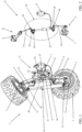
Figure 1 shows a view of the trolley unit for a reversible ploughing system according to the present invention; -
Figure 2 shows a perspective view of a component of the trolley unit for a reversible ploughing system according to the present invention; -
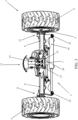
Figure 3 shows a perspective view of the trolley unit according to the present invention with the wheels in an operating circulating position; -
Figure 4 shows a perspective view of the trolley unit according to the present invention with the wheels in an intermediate operating position between the operating circulating position and an operating working position; -
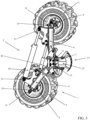
Figure 5 shows a perspective view of the trolley unit according to the present invention in a first possible operating working configuration with the wheels in an operating working position; -
Figure 6 shows a perspective view of the trolley unit according to the present invention in a second possible operating working configuration;
and -
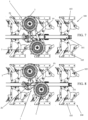
Figures 7 and 8 show side views of a preferred embodiment of a reversible ploughing system according to the present invention with the trolley unit, respectively, in the first operating working configuration ofFigure 5 and in the second operating working configuration ofFigure 6 . - For briefness, herein below the descriptions related to parts and components common with other trolley units and ploughing systems will not be provided, since they are not necessary for their basic operation and/or already known in the art, to describe in particular those aspects, components and operating principles characterizing the trolley unit and the reversible ploughing system according to the present invention.
- With reference therefore in particular to
Figure 1 , it is noted that thetrolley unit 1 according to the present invention comprises at least twowheels 3, an actuatingsystem 2 and at least onetransmission system 17, such actuatingsystem 2 operatively cooperating withsuch transmission system 17 both for passingsuch wheels 3 from an operating circulating position to an operating working position, and vice versa, and for changing an operating working configuration ofsuch trolley unit 1, preferably modifying the distance between the wheels 3 (for example at least when thewheels 3 are in their operating working position). - In a preferred and example embodiment thereof, the
trolley unit 1 according to the present invention then comprises: - at least one central articulating
assembly 7; - at least two
wheels 3, each of which is connected to a respectiverotary hub 5; - at least one pair of
drive shafts 9, each ofsuch drive shafts 9 having a first end connected to acorresponding hub 5 by interposing aarticulating kinematism 11, preferably of the hinge type, and a second end pivotally connected to such central articulatingassembly 7 in arespective articulation point 13, thetransmission system 17 being operatively interposed between thedrive shafts 9. - From
Figures 1 and 2 , it is noted that, in particular, thetransmission system 17 comprises at least onearticulated kinematism 14 composed of at least one second variablelength handling device 26, preferably a second hydraulic jack supplied by asuitable tank 27 containing an hydraulic fluid, common to a pair of articulated transmissions, each of which related to arespective hub 5, each of the articulated transmissions comprising: - at least one
first arm 18; - at least one
second arm 20; - at least one joining
rod 15; - The actuating
system 2 comprises, preferably, at least one first variablelength handling device 19, for example of the type with hydraulic jack, mutually operatively connecting thedrive shafts 9 inrespective articulation points 21 and adjustable in length depending on the operating position of thewheels 3 and/or on the operating working configuration of thetrolley unit 1 which has to be obtained. In particular, such variable-length handling device can have its respective ends connected articulated to arespective drive shaft 9, preferably next to each first end of these latter ones in therespective articulation points 21. - The first variable
length handling device 19 will then have a first running position adapted to move, through the cooperation of thetransmission system 18, thewheels 3 from their operating circulating position to their operating working position, and vice versa, by acting on the respectivearticulating kinematism 11; the variable-length handling device 19 will then have a second running portion adapted to take thetrolley unit 1 according to the present invention to various operating working configurations. - With reference now, in particular, to
Figures 3 ,4 and5 , it is possible to note the passage of thewheels 3 from their operating circulating position to their operating working position:Figure 3 then shows thetrolley unit 1 in which thewheels 3 are in their operating circulating position, having their rotation axes around their respective, substantially coinciding hubs. The coupling variable-length handling device 19 along its own first running position decreases the subtended angle between thedrive shafts 9 and, through thearticulated kinematism 18 of thetransmission system 17, the progressive divergence of thewheels 3, and of their respective rotation axes, till thewheels 3 are taken to their operating working position, as shown inFigure 5 (in which, preferably, the rotation axes of thewheels 3 are substantially mutually parallel) passing through the intermediate operating position of thewheels 3 shown inFigure 4 . Obviously, the contrary movement of the variable-length handling device 19, namely its elongation along its own first running position, allows, in cooperation with thearticulated kinematism 18 of thetransmission system 17, the reverse passage, namely the passage of thewheels 3 from their operating working position to their operating circulating position. - The
actuating system 2, and in particular the variable-length handling device 19, is further adapted to change the distance between thewheels 3, for example at least when they are in their operating working position, to maketrolley unit 1 according to the present invention assume various operating working configurations, each of such configurations being determined by the distance set between such wheels by such variable-length handling device 19, in particular by changing the subtended angle between thedrive shafts 9. With reference then, in particular, toFigures 5 and6 , it is possible to note the passage, determined by the further elongation or shortening of the variable-length handling device 19 along its own second running portion, of thetrolley unit 1 according to the present invention between two possible working configurations, once thewheels 3 have been taken to their operating working position. -
Figure 5 then shows thetrolley unit 1 in which thewheels 3 are at their maximum mutual distance allowed by the shape of the actuatingsystem 2 and of the transmission system 17: in particular, in such operating configuration, the variable-length handling device 19 is in a position of maximum extension along its own second running portion. -
Figure 6 instead shows thetrolley unit 1 in which thewheels 3 are at their minimum mutual distance allowed by the shape of thesecond actuating system 2 and of the transmission system 17: in particular, in such operating configuration, the variable-length handling device 19 is in a position of minimum extension along its own second running portion. - Obviously, the
trolley unit 1 according to the present invention can assume any further operating working configuration included between the two limit operating configurations shown inFigures 5 and6 depending on the distance between thewheels 3, and in particular the subtended angle between thedrive shafts 9, determined by the length assumed by the variable-length handling device 19 along its own second running portion. - With the above described arrangement, the second variable
length handling device 26 coupled with the first variable length handling device 19 (which operates as accumulator or hydraulic spring) has the task of keeping thewheels 3 correctly oriented during the working phase (phase in which it works by thrusting two to the pressure of the first variable length handling device 19: this occurs for a good part of the excursion of the first variablelength handling device 19 dedicated to regulating the ploughing depth. - By increasing the length of the first variable
length handling device 19, the working depth decreases, and also the second variablelength handling device 26 is elongated, but continues keeping thewheels 3 in their working positions, until the second variablelength handling device 26 reaches its maximum extension: it then ends its function of a spring and becomes a sort of tie-rod, further increasing the extension of the first variable length handling device 19 (which still has part of its working stroke available), while the traction on the leverages of the second variablelength handling device 26 rotates the hubs, positioning thewheels 3 in their transport configuration. - The present invention further refers to a reversible ploughing system comprising at least one
trolley unit 1 as previously described. - With reference in particular to
Figures 7 and 8 , a preferred embodiment of the reversible ploughing system according to the present invention is shown and described. - Such system substantially comprises a supporting
frame 101 equipped wih a plurality ofploughing units 103. Theploughing units 103, being known in the art and not being part of the present invention, will not be further described in detail. The supportingframe 101 is adapted to be connected to transporting and working means, such as for example a common agricultural tractor (not shown) through an orientable fastening system (not shown) which makes it possible for the reversible ploughing system to assume two operating positions, namely the circulating position for transporting to the working place and the actual ploughing working position: also the fastening head, being known in the art and not being part of the present invention, will not be further described in detail. - The
reversible ploughing system 100 of the invention further comprises at least onetrolley unit 1 like the previously described one, connected to the supportingframe 101, to innovatively allow it to be transported to its working place. - Obviously, the hydraulic jack possibly composing the variable-
length handling device 19 of thetrolley unit 1 can be advantageously connected to a suitable single connector available on the tractor to exploit the hydraulic plant and its related commands and leaving free further possible connectors for other applications, if necessary. - As stated, the
trolley unit 1 allows both changing the position and the orientation of thewheels 3 between an operating circulating position and an operating working position, and vice versa, and assuming one among different possible operating working configurations through asingle actuating system 2 cooperating with thetransmission system 17. - For the circulation on roads, it will then be enough to place the wheels of the trolley unit in their operating circulating position and the supporting
frame 101 with itsrelated ploughing units 103 in a substantially horizontal position. - Instead, to perform the actual ploughing work, it will be enough to take the supporting
frame 101 with itsrelated ploughing units 103 to a substantially vertical position and thewheels 3 of thetrolley unit 1 in their operating working position: now, it is possible to advantageously regulate also the ploughing depth by acting on the actuatingsystem 2, modifying the distance between the wheels 3: in particular, and wholly as an example,Figure 7 shows thereversible ploughing system 100 according to the present invention with thetrolley unit 1 in its operating working configuration (corresponding to the one shown inFigure 5 ) which allows a minimum ploughing depth, whileFigure 8 shows thereversible ploughing system 100 according to the present invention with thetrolley unit 1 in its operating working configuration (corresponding to the one shown inFigure 6 ) which allows a maximum ploughing depth. - Obviously, the
ploughing system 100 according to the present invention can operate with different ploughing depths included among those shown above as an example, taking thetrolley unit 1 according to the present invention to assume any further operating working configuration included between the two limit operating configurations shown inFigures 5 and6 depending on the the distance between thewheels 3 determined by thehandling device 19 and, in particular, by the length assumed by the variable-length handling device 19.
Claims (7)
- Trolley unit (1) for ploughing systems comprising at least two wheels (3), an actuating system (2), comprising a first variable length handling device (19), and at least one transmission system (17), said actuating system (2) operatively cooperating with said transmission system (17) both for passing said wheels (3) from an operating position of road circulation to an operating position of ploughing work through a rotation, and vice versa, and for changing an operating configuration of ploughing work of said trolley unit (1), said transmission system (17) comprising at least one articulated kinematism (14) composed of at least one second variable length handling device (26) common to a pair of articulated transmissions, each of said articulated transmissions being operatively connected to a respective hub (5), each of said articulated transmissions comprising at least one first arm (18), at least one second arm (20), at least one joining rod (15), said joining rod (15) having a first end connected to said hub (5) by interposing a respective articulating kinematism (11) and a second end connected articulated to a first end of said first arm (18), said first arm (18) having a second end connected articulated to a first end of said second arm (20), said first end of said second arm (20) and said second end of said first arm (18) being further connected articulated to a fixed spot (22) of a respective drive shaft (9), said second arm (20) having a second end hinged to said second variable length handling device (26), wherein said second ends of said second arms (20) are mutually cooperating by interposing said second variable length handling device (26) composed of a second hydraulic jack functioning both as spring, and as tie-rod, wherein said actuating system (2) changes an operating working configuration of said trolley unit (1) by modifying a distance between the circumferences of said wheels (3), or said actuating system (2) changes an operating working configuration of said trolley unit (1) by modifying a distance between said wheels (3) when said wheels (3) are in said operating working position.
- Trolley unit (1) according to claim 1, characterized in that it comprises:- at least one central articulating assembly (7);- at least two of said wheels (3), each of which is connected to said rotary hub (5);- at least one pair of drive shafts (9), each of said drive shafts (9) having a first end connected to a corresponding hub (5) by interposing an articulating kinematism (11) and a second end pivotally connected to said central articulating assembly (7) in a respective articulation point (13), said transmission system (17) being operatively interposed between said drive shafts (9).
- Trolley unit (1) according to the previous claim, characterized in that said articulating kinematism (11) is of a hinge type.
- Trolley unit (1) according to the previous claim, characterized in that said fixed spot (22) is arranged along a projecting element (24) of said drive shaft (9).
- Trolley unit (1) according to any one of the previous claims, characterized in that said first variable length handling device (19) mutually operatively connects said drive shafts (9) in respective articulation points (21) and is adjustable in length depending on said operating position of said wheels (3) and/or of said operating working configuration of said trolley unit (1) to be obtained.
- Trolley unit (1) according to the previous claim, characterized in that said first variable length handling device (19) has a first running position adapted to move, through the cooperation of said transmission system (18), said wheels (3) from said operating circulating position to said operating working position, and vice versa, by acting on said respective articulating kinematism (11), and a second running portion adapted to take said trolley unit (1) to various of said operating working configurations.
- Reversible ploughing system (100) characterized in that it comprises at least one trolley unit (1) according to any one of the previous claims.
Applications Claiming Priority (2)
| Application Number | Priority Date | Filing Date | Title |
|---|---|---|---|
| IT102019000019804A IT201900019804A1 (en) | 2019-10-25 | 2019-10-25 | Improved trolley assembly, in particular for reversible plowing system, and reversible plowing system comprising such a trolley assembly |
| PCT/IT2020/050210 WO2021079388A1 (en) | 2019-10-25 | 2020-08-31 | Improved trolley unit, in particular for a reversible ploughing system, and reversible ploughing system comprising such trolley unit |
Publications (2)
| Publication Number | Publication Date |
|---|---|
| EP4048047A1 EP4048047A1 (en) | 2022-08-31 |
| EP4048047B1 true EP4048047B1 (en) | 2024-07-31 |
Family
ID=69743781
Family Applications (1)
| Application Number | Title | Priority Date | Filing Date |
|---|---|---|---|
| EP20765102.7A Active EP4048047B1 (en) | 2019-10-25 | 2020-08-31 | Improved trolley unit, in particular for a reversible ploughing system, and reversible ploughing system comprising such trolley unit |
Country Status (3)
| Country | Link |
|---|---|
| EP (1) | EP4048047B1 (en) |
| IT (1) | IT201900019804A1 (en) |
| WO (1) | WO2021079388A1 (en) |
Families Citing this family (1)
| Publication number | Priority date | Publication date | Assignee | Title |
|---|---|---|---|---|
| IT202200019491A1 (en) * | 2022-09-22 | 2024-03-22 | Nardi Srl | PLOUGH WHEEL ADJUSTMENT SYSTEM |
Family Cites Families (6)
| Publication number | Priority date | Publication date | Assignee | Title |
|---|---|---|---|---|
| GB1023095A (en) * | 1963-11-20 | 1966-03-16 | Brown Tractors Ltd | Improvements in or relating to ploughs |
| IT1309501B1 (en) | 1999-11-09 | 2002-01-23 | Moro Aratri S R L | PERFECTED SYSTEM FOR Plowing. |
| US7963361B2 (en) * | 2008-09-24 | 2011-06-21 | Deere & Company | Steering axle transport positioning structure and method |
| US9174488B2 (en) * | 2012-03-19 | 2015-11-03 | Jlg Industries, Inc. | Pivoting axle system |
| BE1022805B1 (en) * | 2015-02-18 | 2016-09-09 | Cnh Industrial Belgium Nv | Support frame for agricultural vehicle |
| IT201800009916A1 (en) * | 2018-10-30 | 2019-01-30 | Moro Aratri Srl | IMPROVED TROLLEY GROUP, IN PARTICULAR FOR THE REVERSIBLE PLOWING SYSTEM, AND REVERSIBLE PLOWING SYSTEM INCLUDING SUCH A TROLLEY GROUP. |
-
2019
- 2019-10-25 IT IT102019000019804A patent/IT201900019804A1/en unknown
-
2020
- 2020-08-31 EP EP20765102.7A patent/EP4048047B1/en active Active
- 2020-08-31 WO PCT/IT2020/050210 patent/WO2021079388A1/en not_active Ceased
Also Published As
| Publication number | Publication date |
|---|---|
| WO2021079388A1 (en) | 2021-04-29 |
| EP4048047A1 (en) | 2022-08-31 |
| IT201900019804A1 (en) | 2020-01-25 |
Similar Documents
| Publication | Publication Date | Title |
|---|---|---|
| US9883621B2 (en) | Soil working machines including height and pitch tool adjustability | |
| EP2306804B1 (en) | Adjustable and foldable v-shaped hay rake | |
| US20090084566A1 (en) | Hitch device for a working vehicle | |
| US8240418B2 (en) | Pivot-steered vehicle | |
| EP4048047B1 (en) | Improved trolley unit, in particular for a reversible ploughing system, and reversible ploughing system comprising such trolley unit | |
| EP3646687B1 (en) | Improved carriage assembly, in particular for reversible plowing system, and reversible plowing system comprising such carriage assembly | |
| US3616893A (en) | Mobile hydraulically foldable conveyor | |
| DE102014000236B4 (en) | Ground milling machine with a construction machine steering device | |
| US11879221B2 (en) | Snow tiller and method of adjusting the same | |
| US3528519A (en) | Speed,steering and direction control for vehicles | |
| KR102720205B1 (en) | Steerable agricultural remote driving vehicle | |
| DE102012006290A1 (en) | hydrotransformer | |
| US2742100A (en) | Earth mover power steering mechanism | |
| CA2932357A1 (en) | Steering mechanism for transport equipment | |
| US2676664A (en) | Steering apparatus for motor powered vehicles | |
| US20010020558A1 (en) | Steering device for axles | |
| US3424023A (en) | Steering control system | |
| CN116075214A (en) | Mounted reversible plow | |
| CN110758556B (en) | A wheeled agricultural machinery front and rear wheel tracking control mechanism | |
| US5944116A (en) | Apparatus for positioning a work object | |
| US6896069B2 (en) | Roll-over disk plow | |
| EP4175450B1 (en) | Mounted reversible plough | |
| PL239447B1 (en) | Tedder-rotary rake | |
| EP3228525A1 (en) | Powered steering trolley and transport vehicle provided with such trolley | |
| SU1657085A1 (en) | Half-mounted coupling frame |
Legal Events
| Date | Code | Title | Description |
|---|---|---|---|
| STAA | Information on the status of an ep patent application or granted ep patent |
Free format text: STATUS: UNKNOWN |
|
| STAA | Information on the status of an ep patent application or granted ep patent |
Free format text: STATUS: THE INTERNATIONAL PUBLICATION HAS BEEN MADE |
|
| PUAI | Public reference made under article 153(3) epc to a published international application that has entered the european phase |
Free format text: ORIGINAL CODE: 0009012 |
|
| STAA | Information on the status of an ep patent application or granted ep patent |
Free format text: STATUS: REQUEST FOR EXAMINATION WAS MADE |
|
| 17P | Request for examination filed |
Effective date: 20220412 |
|
| AK | Designated contracting states |
Kind code of ref document: A1 Designated state(s): AL AT BE BG CH CY CZ DE DK EE ES FI FR GB GR HR HU IE IS IT LI LT LU LV MC MK MT NL NO PL PT RO RS SE SI SK SM TR |
|
| DAV | Request for validation of the european patent (deleted) | ||
| DAX | Request for extension of the european patent (deleted) | ||
| GRAP | Despatch of communication of intention to grant a patent |
Free format text: ORIGINAL CODE: EPIDOSNIGR1 |
|
| STAA | Information on the status of an ep patent application or granted ep patent |
Free format text: STATUS: GRANT OF PATENT IS INTENDED |
|
| INTG | Intention to grant announced |
Effective date: 20240306 |
|
| GRAS | Grant fee paid |
Free format text: ORIGINAL CODE: EPIDOSNIGR3 |
|
| GRAA | (expected) grant |
Free format text: ORIGINAL CODE: 0009210 |
|
| STAA | Information on the status of an ep patent application or granted ep patent |
Free format text: STATUS: THE PATENT HAS BEEN GRANTED |
|
| AK | Designated contracting states |
Kind code of ref document: B1 Designated state(s): AL AT BE BG CH CY CZ DE DK EE ES FI FR GB GR HR HU IE IS IT LI LT LU LV MC MK MT NL NO PL PT RO RS SE SI SK SM TR |
|
| REG | Reference to a national code |
Ref country code: CH Ref legal event code: EP Ref country code: GB Ref legal event code: FG4D |
|
| REG | Reference to a national code |
Ref country code: DE Ref legal event code: R096 Ref document number: 602020034910 Country of ref document: DE |
|
| REG | Reference to a national code |
Ref country code: IE Ref legal event code: FG4D |
|
| REG | Reference to a national code |
Ref country code: LT Ref legal event code: MG9D |
|
| REG | Reference to a national code |
Ref country code: NL Ref legal event code: MP Effective date: 20240731 |
|
| PG25 | Lapsed in a contracting state [announced via postgrant information from national office to epo] |
Ref country code: PT Free format text: LAPSE BECAUSE OF FAILURE TO SUBMIT A TRANSLATION OF THE DESCRIPTION OR TO PAY THE FEE WITHIN THE PRESCRIBED TIME-LIMIT Effective date: 20241202 |
|
| REG | Reference to a national code |
Ref country code: AT Ref legal event code: MK05 Ref document number: 1707517 Country of ref document: AT Kind code of ref document: T Effective date: 20240731 |
|
| PG25 | Lapsed in a contracting state [announced via postgrant information from national office to epo] |
Ref country code: PT Free format text: LAPSE BECAUSE OF FAILURE TO SUBMIT A TRANSLATION OF THE DESCRIPTION OR TO PAY THE FEE WITHIN THE PRESCRIBED TIME-LIMIT Effective date: 20241202 |
|
| PG25 | Lapsed in a contracting state [announced via postgrant information from national office to epo] |
Ref country code: NO Free format text: LAPSE BECAUSE OF FAILURE TO SUBMIT A TRANSLATION OF THE DESCRIPTION OR TO PAY THE FEE WITHIN THE PRESCRIBED TIME-LIMIT Effective date: 20241031 |
|
| PG25 | Lapsed in a contracting state [announced via postgrant information from national office to epo] |
Ref country code: FI Free format text: LAPSE BECAUSE OF FAILURE TO SUBMIT A TRANSLATION OF THE DESCRIPTION OR TO PAY THE FEE WITHIN THE PRESCRIBED TIME-LIMIT Effective date: 20240731 Ref country code: NL Free format text: LAPSE BECAUSE OF FAILURE TO SUBMIT A TRANSLATION OF THE DESCRIPTION OR TO PAY THE FEE WITHIN THE PRESCRIBED TIME-LIMIT Effective date: 20240731 Ref country code: PL Free format text: LAPSE BECAUSE OF FAILURE TO SUBMIT A TRANSLATION OF THE DESCRIPTION OR TO PAY THE FEE WITHIN THE PRESCRIBED TIME-LIMIT Effective date: 20240731 Ref country code: GR Free format text: LAPSE BECAUSE OF FAILURE TO SUBMIT A TRANSLATION OF THE DESCRIPTION OR TO PAY THE FEE WITHIN THE PRESCRIBED TIME-LIMIT Effective date: 20241101 |
|
| PG25 | Lapsed in a contracting state [announced via postgrant information from national office to epo] |
Ref country code: BG Free format text: LAPSE BECAUSE OF FAILURE TO SUBMIT A TRANSLATION OF THE DESCRIPTION OR TO PAY THE FEE WITHIN THE PRESCRIBED TIME-LIMIT Effective date: 20240731 |
|
| PG25 | Lapsed in a contracting state [announced via postgrant information from national office to epo] |
Ref country code: LV Free format text: LAPSE BECAUSE OF FAILURE TO SUBMIT A TRANSLATION OF THE DESCRIPTION OR TO PAY THE FEE WITHIN THE PRESCRIBED TIME-LIMIT Effective date: 20240731 |
|
| PG25 | Lapsed in a contracting state [announced via postgrant information from national office to epo] |
Ref country code: IS Free format text: LAPSE BECAUSE OF FAILURE TO SUBMIT A TRANSLATION OF THE DESCRIPTION OR TO PAY THE FEE WITHIN THE PRESCRIBED TIME-LIMIT Effective date: 20241130 Ref country code: AT Free format text: LAPSE BECAUSE OF FAILURE TO SUBMIT A TRANSLATION OF THE DESCRIPTION OR TO PAY THE FEE WITHIN THE PRESCRIBED TIME-LIMIT Effective date: 20240731 |
|
| PG25 | Lapsed in a contracting state [announced via postgrant information from national office to epo] |
Ref country code: HR Free format text: LAPSE BECAUSE OF FAILURE TO SUBMIT A TRANSLATION OF THE DESCRIPTION OR TO PAY THE FEE WITHIN THE PRESCRIBED TIME-LIMIT Effective date: 20240731 |
|
| PG25 | Lapsed in a contracting state [announced via postgrant information from national office to epo] |
Ref country code: RS Free format text: LAPSE BECAUSE OF FAILURE TO SUBMIT A TRANSLATION OF THE DESCRIPTION OR TO PAY THE FEE WITHIN THE PRESCRIBED TIME-LIMIT Effective date: 20241031 Ref country code: ES Free format text: LAPSE BECAUSE OF FAILURE TO SUBMIT A TRANSLATION OF THE DESCRIPTION OR TO PAY THE FEE WITHIN THE PRESCRIBED TIME-LIMIT Effective date: 20240731 |
|
| PG25 | Lapsed in a contracting state [announced via postgrant information from national office to epo] |
Ref country code: RS Free format text: LAPSE BECAUSE OF FAILURE TO SUBMIT A TRANSLATION OF THE DESCRIPTION OR TO PAY THE FEE WITHIN THE PRESCRIBED TIME-LIMIT Effective date: 20241031 Ref country code: PL Free format text: LAPSE BECAUSE OF FAILURE TO SUBMIT A TRANSLATION OF THE DESCRIPTION OR TO PAY THE FEE WITHIN THE PRESCRIBED TIME-LIMIT Effective date: 20240731 Ref country code: NO Free format text: LAPSE BECAUSE OF FAILURE TO SUBMIT A TRANSLATION OF THE DESCRIPTION OR TO PAY THE FEE WITHIN THE PRESCRIBED TIME-LIMIT Effective date: 20241031 Ref country code: NL Free format text: LAPSE BECAUSE OF FAILURE TO SUBMIT A TRANSLATION OF THE DESCRIPTION OR TO PAY THE FEE WITHIN THE PRESCRIBED TIME-LIMIT Effective date: 20240731 Ref country code: LV Free format text: LAPSE BECAUSE OF FAILURE TO SUBMIT A TRANSLATION OF THE DESCRIPTION OR TO PAY THE FEE WITHIN THE PRESCRIBED TIME-LIMIT Effective date: 20240731 Ref country code: IS Free format text: LAPSE BECAUSE OF FAILURE TO SUBMIT A TRANSLATION OF THE DESCRIPTION OR TO PAY THE FEE WITHIN THE PRESCRIBED TIME-LIMIT Effective date: 20241130 Ref country code: HR Free format text: LAPSE BECAUSE OF FAILURE TO SUBMIT A TRANSLATION OF THE DESCRIPTION OR TO PAY THE FEE WITHIN THE PRESCRIBED TIME-LIMIT Effective date: 20240731 Ref country code: GR Free format text: LAPSE BECAUSE OF FAILURE TO SUBMIT A TRANSLATION OF THE DESCRIPTION OR TO PAY THE FEE WITHIN THE PRESCRIBED TIME-LIMIT Effective date: 20241101 Ref country code: FI Free format text: LAPSE BECAUSE OF FAILURE TO SUBMIT A TRANSLATION OF THE DESCRIPTION OR TO PAY THE FEE WITHIN THE PRESCRIBED TIME-LIMIT Effective date: 20240731 Ref country code: ES Free format text: LAPSE BECAUSE OF FAILURE TO SUBMIT A TRANSLATION OF THE DESCRIPTION OR TO PAY THE FEE WITHIN THE PRESCRIBED TIME-LIMIT Effective date: 20240731 Ref country code: BG Free format text: LAPSE BECAUSE OF FAILURE TO SUBMIT A TRANSLATION OF THE DESCRIPTION OR TO PAY THE FEE WITHIN THE PRESCRIBED TIME-LIMIT Effective date: 20240731 Ref country code: AT Free format text: LAPSE BECAUSE OF FAILURE TO SUBMIT A TRANSLATION OF THE DESCRIPTION OR TO PAY THE FEE WITHIN THE PRESCRIBED TIME-LIMIT Effective date: 20240731 |
|
| REG | Reference to a national code |
Ref country code: CH Ref legal event code: PL |
|
| PG25 | Lapsed in a contracting state [announced via postgrant information from national office to epo] |
Ref country code: SM Free format text: LAPSE BECAUSE OF FAILURE TO SUBMIT A TRANSLATION OF THE DESCRIPTION OR TO PAY THE FEE WITHIN THE PRESCRIBED TIME-LIMIT Effective date: 20240731 Ref country code: DK Free format text: LAPSE BECAUSE OF FAILURE TO SUBMIT A TRANSLATION OF THE DESCRIPTION OR TO PAY THE FEE WITHIN THE PRESCRIBED TIME-LIMIT Effective date: 20240731 Ref country code: RO Free format text: LAPSE BECAUSE OF FAILURE TO SUBMIT A TRANSLATION OF THE DESCRIPTION OR TO PAY THE FEE WITHIN THE PRESCRIBED TIME-LIMIT Effective date: 20240731 |
|
| PG25 | Lapsed in a contracting state [announced via postgrant information from national office to epo] |
Ref country code: LU Free format text: LAPSE BECAUSE OF NON-PAYMENT OF DUE FEES Effective date: 20240831 |
|
| PG25 | Lapsed in a contracting state [announced via postgrant information from national office to epo] |
Ref country code: MC Free format text: LAPSE BECAUSE OF FAILURE TO SUBMIT A TRANSLATION OF THE DESCRIPTION OR TO PAY THE FEE WITHIN THE PRESCRIBED TIME-LIMIT Effective date: 20240731 Ref country code: CH Free format text: LAPSE BECAUSE OF NON-PAYMENT OF DUE FEES Effective date: 20240831 Ref country code: EE Free format text: LAPSE BECAUSE OF FAILURE TO SUBMIT A TRANSLATION OF THE DESCRIPTION OR TO PAY THE FEE WITHIN THE PRESCRIBED TIME-LIMIT Effective date: 20240731 |
|
| PG25 | Lapsed in a contracting state [announced via postgrant information from national office to epo] |
Ref country code: CZ Free format text: LAPSE BECAUSE OF FAILURE TO SUBMIT A TRANSLATION OF THE DESCRIPTION OR TO PAY THE FEE WITHIN THE PRESCRIBED TIME-LIMIT Effective date: 20240731 |
|
| PG25 | Lapsed in a contracting state [announced via postgrant information from national office to epo] |
Ref country code: SK Free format text: LAPSE BECAUSE OF FAILURE TO SUBMIT A TRANSLATION OF THE DESCRIPTION OR TO PAY THE FEE WITHIN THE PRESCRIBED TIME-LIMIT Effective date: 20240731 |
|
| REG | Reference to a national code |
Ref country code: DE Ref legal event code: R097 Ref document number: 602020034910 Country of ref document: DE |
|
| PLBE | No opposition filed within time limit |
Free format text: ORIGINAL CODE: 0009261 |
|
| STAA | Information on the status of an ep patent application or granted ep patent |
Free format text: STATUS: NO OPPOSITION FILED WITHIN TIME LIMIT |
|
| GBPC | Gb: european patent ceased through non-payment of renewal fee |
Effective date: 20241031 |
|
| REG | Reference to a national code |
Ref country code: BE Ref legal event code: MM Effective date: 20240831 |
|
| 26N | No opposition filed |
Effective date: 20250501 |
|
| PG25 | Lapsed in a contracting state [announced via postgrant information from national office to epo] |
Ref country code: GB Free format text: LAPSE BECAUSE OF NON-PAYMENT OF DUE FEES Effective date: 20241031 |
|
| PG25 | Lapsed in a contracting state [announced via postgrant information from national office to epo] |
Ref country code: BE Free format text: LAPSE BECAUSE OF NON-PAYMENT OF DUE FEES Effective date: 20240831 Ref country code: IT Free format text: LAPSE BECAUSE OF NON-PAYMENT OF DUE FEES Effective date: 20240831 |
|
| PG25 | Lapsed in a contracting state [announced via postgrant information from national office to epo] |
Ref country code: IE Free format text: LAPSE BECAUSE OF NON-PAYMENT OF DUE FEES Effective date: 20240831 |
|
| PG25 | Lapsed in a contracting state [announced via postgrant information from national office to epo] |
Ref country code: SE Free format text: LAPSE BECAUSE OF FAILURE TO SUBMIT A TRANSLATION OF THE DESCRIPTION OR TO PAY THE FEE WITHIN THE PRESCRIBED TIME-LIMIT Effective date: 20240731 |
|
| PGFP | Annual fee paid to national office [announced via postgrant information from national office to epo] |
Ref country code: DE Payment date: 20250827 Year of fee payment: 6 |
|
| PGFP | Annual fee paid to national office [announced via postgrant information from national office to epo] |
Ref country code: FR Payment date: 20250825 Year of fee payment: 6 |
|
| PG25 | Lapsed in a contracting state [announced via postgrant information from national office to epo] |
Ref country code: CY Free format text: LAPSE BECAUSE OF FAILURE TO SUBMIT A TRANSLATION OF THE DESCRIPTION OR TO PAY THE FEE WITHIN THE PRESCRIBED TIME-LIMIT; INVALID AB INITIO Effective date: 20200831 |
|
| PG25 | Lapsed in a contracting state [announced via postgrant information from national office to epo] |
Ref country code: HU Free format text: LAPSE BECAUSE OF FAILURE TO SUBMIT A TRANSLATION OF THE DESCRIPTION OR TO PAY THE FEE WITHIN THE PRESCRIBED TIME-LIMIT; INVALID AB INITIO Effective date: 20200831 |