EP4048022A1 - Systems and methods for avoiding interference between wireless devices in a wireless network - Google Patents
Systems and methods for avoiding interference between wireless devices in a wireless network Download PDFInfo
- Publication number
- EP4048022A1 EP4048022A1 EP22157243.1A EP22157243A EP4048022A1 EP 4048022 A1 EP4048022 A1 EP 4048022A1 EP 22157243 A EP22157243 A EP 22157243A EP 4048022 A1 EP4048022 A1 EP 4048022A1
- Authority
- EP
- European Patent Office
- Prior art keywords
- sta
- wireless
- transmission
- rssi
- stas
- Prior art date
- Legal status (The legal status is an assumption and is not a legal conclusion. Google has not performed a legal analysis and makes no representation as to the accuracy of the status listed.)
- Granted
Links
Images





Classifications
-
- H—ELECTRICITY
- H04—ELECTRIC COMMUNICATION TECHNIQUE
- H04W—WIRELESS COMMUNICATION NETWORKS
- H04W28/00—Network traffic management; Network resource management
- H04W28/16—Central resource management; Negotiation of resources or communication parameters, e.g. negotiating bandwidth or QoS [Quality of Service]
- H04W28/18—Negotiating wireless communication parameters
-
- H—ELECTRICITY
- H04—ELECTRIC COMMUNICATION TECHNIQUE
- H04W—WIRELESS COMMUNICATION NETWORKS
- H04W72/00—Local resource management
- H04W72/50—Allocation or scheduling criteria for wireless resources
- H04W72/54—Allocation or scheduling criteria for wireless resources based on quality criteria
- H04W72/542—Allocation or scheduling criteria for wireless resources based on quality criteria using measured or perceived quality
-
- H—ELECTRICITY
- H04—ELECTRIC COMMUNICATION TECHNIQUE
- H04B—TRANSMISSION
- H04B1/00—Details of transmission systems, not covered by a single one of groups H04B3/00 - H04B13/00; Details of transmission systems not characterised by the medium used for transmission
- H04B1/02—Transmitters
- H04B1/04—Circuits
- H04B1/0475—Circuits with means for limiting noise, interference or distortion
-
- H—ELECTRICITY
- H04—ELECTRIC COMMUNICATION TECHNIQUE
- H04B—TRANSMISSION
- H04B17/00—Monitoring; Testing
- H04B17/30—Monitoring; Testing of propagation channels
- H04B17/309—Measuring or estimating channel quality parameters
- H04B17/318—Received signal strength
-
- H—ELECTRICITY
- H04—ELECTRIC COMMUNICATION TECHNIQUE
- H04W—WIRELESS COMMUNICATION NETWORKS
- H04W72/00—Local resource management
- H04W72/04—Wireless resource allocation
-
- H—ELECTRICITY
- H04—ELECTRIC COMMUNICATION TECHNIQUE
- H04W—WIRELESS COMMUNICATION NETWORKS
- H04W72/00—Local resource management
- H04W72/50—Allocation or scheduling criteria for wireless resources
- H04W72/54—Allocation or scheduling criteria for wireless resources based on quality criteria
- H04W72/541—Allocation or scheduling criteria for wireless resources based on quality criteria using the level of interference
-
- H—ELECTRICITY
- H04—ELECTRIC COMMUNICATION TECHNIQUE
- H04W—WIRELESS COMMUNICATION NETWORKS
- H04W72/00—Local resource management
- H04W72/12—Wireless traffic scheduling
- H04W72/121—Wireless traffic scheduling for groups of terminals or users
-
- H—ELECTRICITY
- H04—ELECTRIC COMMUNICATION TECHNIQUE
- H04W—WIRELESS COMMUNICATION NETWORKS
- H04W84/00—Network topologies
- H04W84/02—Hierarchically pre-organised networks, e.g. paging networks, cellular networks, WLAN [Wireless Local Area Network] or WLL [Wireless Local Loop]
- H04W84/10—Small scale networks; Flat hierarchical networks
- H04W84/12—WLAN [Wireless Local Area Networks]
Definitions
- Embodiments of the present invention generally relate to the field of wireless communications. More specifically, embodiments of the present invention relate to systems and methods for mitigating signal interference between devices in close physical proximity in a wireless communication network.
- Many modern electronic devices send and receive data with other electronic devices wirelessly using Wi-Fi, and several devices may be communicating over bands or channels that are close in frequency within the same physical location, such as a home, office, or library. Often these devices, including smartphones, tablets, and laptop computers, are connected to the same wireless access point (AP).
- AP wireless access point
- STA transmitting wireless station
- the signal interference e.g., alternative adjacent channel interference (AACI)
- AACI alternative adjacent channel interference
- This negative impact on sensitivity is referred to as "desense" and typically occurs when two operating bands are close in frequency and have inadequate isolation and filtering to prevent energy leakage from sidebands.
- the unwanted desense can be caused by different wireless devices that are operating close to each other (inter-device desense) or different wireless stations (STAs) of the same multi-band device (in-device desense).
- inter-device desense or different wireless stations (STAs) of the same multi-band device (in-device desense).
- STAs wireless stations
- the defense problem is magnified when the STAs are close in physical proximity to each other but far away from the AP.
- ISR I/S
- embodiments of the present invention substantially mitigate or prevent in-device and inter-device interference (e.g., AACI) by grouping wireless stations associated with an AP according to their estimated physical proximity with each other.
- the transmissions to/from STAs within a group can be coordinated so that a wireless transmission does not interfere with the wireless reception of another STA within the same group. In this way, desense is avoided and the wireless reception can be performed efficiently.
- a method, a wireless access point, and a non-transitory computer-readable storage medium according to the invention are defined in the independent claims.
- the dependent claims define preferred embodiments thereof.
- program modules include routines, programs, objects, components, data structures, etc. that perform particular tasks or implement particular abstract data types.
- functionality of the program modules may be combined or distributed as desired in various embodiments.
- Embodiments of the present invention substantially mitigate or prevent in-device and inter-device signal interference (e.g., AACI) by advantageously grouping wireless stations associated with an AP according to their estimated physical proximity with each other.
- the STAs within a group can be coordinated so that a wireless transmission does not interfere with a contemporaneous wireless reception of another STA within the same group. In this way, the unwanted effects of desense are avoided and the wireless reception can be performed efficiently.
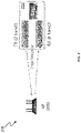
- FIG. 1 is a diagram of an exemplary wireless network 100 including wireless access point 105 associated with STA1 (110) and STA2 (115).
- STA1 and STA2 transmit over different wireless bands that are close in frequency, and STA1 and STA2 are relatively close to each other geographically (e.g., within 5 meters).
- significant signal interference between the STAs e.g., AACI
- the STA that is receiving data will experience a degraded signal (desense) and the transmission will therefore be less efficient.
- the AACI depicted between band1 and band2 in the example of Figure 1 is inter-device interference caused by distinct wireless devices.
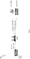
- FIG. 2 is a diagram of an exemplary wireless network 200 including a wireless device 210 experiencing in-device AACI while simultaneously transmitting and receiving data.
- Wireless device 210 may be any one of a number of different well-known components including a wireless smartphone, laptop, or tablet for example, and includes a first wireless station 215 and a second wireless station 220 capable of operation over different wireless bands.
- STA 215 and a STA 220 can be configured to operate simultaneously over wireless bands that are close or similar in frequency. Accordingly, when one of the STAs transmits data wirelessly while the other STA is receiving data wirelessly, or begins transmitting data wirelessly while the other STA is already receiving data wirelessly, significant signal interference between the STAs (e.g., AACI) can cause signal degradation. Specifically, the STA that is receiving data will experience a degraded signal and the transmission will therefore be less efficient.
- the AACI depicted between band1 and band2 in the example of Figure 2 is in-device interference caused by different wireless stations of the same wireless device (e.g., a dual or multi-band wireless device).
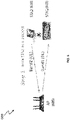
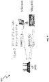
- FIGS 3 and 4 are diagrams of an exemplary wireless network 300 for coordinating transmission between wireless devices grouped based on a received signal strength indicator (RSSI) threshold according to embodiments of the present invention.
- AP 305 is associated with wireless devices STA1 (310) and STA2 (315).
- STA2 may experience desense when receiving data from wireless AP 305 if STA1 begins transmitting to AP 305.
- SAT 2 may experience AACI that is magnified when STA1 and STA2 are in close physical proximity and/or are using bands that are close in frequency. Accordingly, to prevent interference between STA1 and STA2, the STAs associated with AP 305 can detect RSSI and report the detected RSSI to AP 305 for identifying potential interference between the STAs.
- STA1 transmits data to AP 305 causing interference that is detected by STA2.
- STA2 determines if the received interference is from an STA associated with the same AP (i.e. AP 305) as STA2. If the STA is not associated with the same AP (i.e. AP 305) as STA2, the process ends. If STA2 determines that the STA is associated with AP 305, STA2 then determines if the received RSSI from the STA is larger than a predetermined RSSI threshold. As depicted in Figure 4 , if the RSSI received from STA 1 is larger than the RSSI threshold, STA2 reports information associated with STA1 ("transmission information") to AP 305.
- transmission information information associated with STA1
- the information reported by STA2 may include the interference source (e.g., STA ID, MAC address, etc.), the band info (e.g., operating frequency), the received RSSI, etc. Because STA1 and STA2 are associated with AP 305 and the received RSSI is above the threshold, AP 305 advantageously groups STA1 and STA2 to coordinate wireless operations and advantageously prevent interference between the devices.
- the interference source e.g., STA ID, MAC address, etc.
- the band info e.g., operating frequency
- FIG. 5 depicts an exemplary wireless network 500 for coordinating transmission between wireless devices grouped according to RSSI, pathloss (PL), and/or angle of arrival (AOA) according to embodiments of the present invention.
- AP 505 groups associated STAs according to metrics measured at the AP-side. For example, AP 505 can measure RSSI when receiving data from STA1 (510), STA2 (515), and STA3 (520) and calculate path loss information according to the transmission power (TxPwr) of an STA indicated in a trigger-based UL packet.
- AP 505 can also calculate the angle of arrival between AP 505 and an STA and estimate the physical proximity of the devices relative to each other according to the PL and the AOA.
- the AOA can be determined according to channel state information (CSI) of the bands and the antenna pattern of AP 505, for example.
- CSI channel state information
- AP 505 can group the STAs for coordinating transmissions of the STAs to prevent or mitigate signal interference between the group of STAs based on the metrics measured by the AP. For example, if STA1 and STA2 are determined to be in close physical proximity (e.g., within 3 meters) according to the calculated PL and AOA, STA1 and STA2 can be grouped together by AP 505 to coordinate transmissions between the devices. In the example of Figure 5 , AP 505 calculates the PL and AOA associated with STA3 and does not group STA3 with STA1 and STA2 because the PL and AOA information for STA3 are substantially different.
- FIGS 6-8 depict an exemplary wireless network 600 for coordinating transmissions between wireless devices grouped according to receiving failures that coincide with the transmission of an associated STA according to embodiments of the present invention.
- AP 605 can listen over nearby bands (e.g., band 2) while transmitting data to a wireless station over band 1 to determine if the band is busy.
- STA1 (615) is receiving a transmission from AP 605 over band 1 while STA2 (610) is transmitting UL data to AP 605 over band 2.
- AP 605 identifies STA2 a potential source of interference to STA1 if transmissions of the devices transmitted in different directions overlap.
- AP 605 determines that STA1 and STA2 are likely relatively close to each other (e.g., within 3 meters).
- AP 605 can group STA1 and STA2 to coordinate transmissions of the devices for preventing or mitigating interference between the devices (e.g., AACI) after any number of receiving errors are detected.
- AP 605 detects overlapping transmissions. When AP 605 subsequently fails to receive a BA from STA2 while STA1 is transmitting, it is considered further evidence that STA1 and STA2 are in close physical proximity. In this case AP 605 will typically group STA1 and STA2 for coordinated transmission.
- AP 605 may receive a BA from STA1 or STA2 indicating that some of the data transmitted by STA1 or STA2 was successfully received. In the case of a partial transmission failure, AP 605 can determine that STA1 and STA2 are in close physical proximity according to the BA and group the STAs for coordinated transmission.
- AP 905 of exemplary wireless network 900 can use trigger frame (TR) 920 to solicit UL transmission 925 from the STAs to advantageously avoid simultaneous downlink (DL) and UL transmission within the same group according to embodiments of the present invention.
- TR trigger frame
- AP 905 does not schedule a packet for transmission to STA2 that would be transmitted while STA1 is transmitting UL data in response to trigger frame 920. In this way, signal interference between STA1 and STA2 is advantageously avoided.
- FIG. 10 depicts an exemplary wireless network 1000 including STAs in close proximity to each other that do not understand trigger frames (e.g., legacy devices) according to embodiments of the present invention.
- AP 1005 groups associated STAs ("STA groups") according to information collected from the STAs (e.g., RSSI), or according to information calculated by the AP (e.g., RSSI, PL, AOA)
- STA groups associated STAs
- AP 1005 coordinates transmissions between the STAs and the AP to prevent interference between the STAs.
- AP 1005 can avoid scheduling transmissions to STA2 (1015) while receiving UL data from STA1 to advantageously prevent interference between the STAs.
- FIG 11 is a flow chart of an exemplary sequence of computer implemented steps for automatically scheduling transmissions between a wireless access point and its associated wireless devices (STAs) to reduce and/or prevent signal interference between the wireless devices during simultaneous transmission and reception thereof.
- STAs wireless devices
- the AP receives or determines transmission information associated with the STAs directly or indirectly.
- the direct transmission information may include the interference source (e.g., STA ID, MAC address, etc.), the band info (e.g., operating frequency), and/or the received RSSI.
- the direct transmission information can also be received from an STA associated with the AP and can include information pertaining to another associated STA that is suspected of being in close physical proximity to the reporting STA (e.g., based on RSSI).
- Indirect transmission information may include the receiving quality (e.g. information indicated in or derived from BA) and traffic patterns (e.g. indication of overlapping transmission and reception).
- Step 1105 can also include receiving an acknowledgment (e.g., a BA or bitmap) to determine if devices are in close physical proximity according to the successful/unsuccessful transmissions indicated in the acknowledgment.
- the AP assigns groups to associated STAs that are likely to cause signal interference with each other based on the transmission information. For example, associated STAs can be grouped according to their estimated physical proximity with other STAs in the group. According to some embodiments, STAs that are estimated to be within approximately 3 meters are grouped together. Step 1110 can include grouping STAs according to direct information received from the STAs or metrics calculated by the AP, such as PL, AOA, and/or RSSI as well as indirect information, for example.
- direct information received from the STAs or metrics calculated by the AP such as PL, AOA, and/or RSSI as well as indirect information, for example.
- Step 1115 the AP schedules transmissions with the STAs so that simultaneous transmission and reception over bands close in frequency within the group of STAs is avoided.
- Step 1115 includes transmitting trigger frames soliciting uplink transmission from an STA, according to some embodiments. Accordingly, signal interference between STAs within the group is avoided and transmissions between the AP and the STAs are performed efficiently and without reception errors due to desense.
- FIG 12 depicts an exemplary wireless device 1200 upon which embodiments of the present invention can be implemented.
- Embodiments of the present invention automatically transmit and/or schedule to transmit data between a wireless access point and a group of associated wireless devices (STAs) in a manner that advantageously prevents interference between the devices caused by simultaneous transmission and reception over bands close in frequency (AACI).
- STAs wireless devices
- AACI bands close in frequency
- the following discussion describes one such exemplary electronic system or computer system that can be used as a platform for implementing embodiments of the present invention.
- the exemplary computer system 1200 can be a wireless access point or a wireless station, for example.
- the wireless device 1200 includes a processor 1205 for running software applications and optionally an operating system.
- Memory 1210 can include read-only memory and/or random access memory, for example, to store applications and data (e.g., tables of index values) for use by the processor 1205 and data received or transmitted by transceivers 1220, 1225, and 1230 over different wireless links.
- the wireless device 1200 can include fewer or more transceivers according to some embodiments.
- the transceivers 1220, 1225, 1230 communicate with other electronic devices over a wireless network (e.g., WLAN) and typically operates according to IEEE standards (e.g., IEEE 802.11ax, IEEE 802.11ay, IEEE 802.11be, etc.).
Landscapes
- Engineering & Computer Science (AREA)
- Computer Networks & Wireless Communication (AREA)
- Signal Processing (AREA)
- Quality & Reliability (AREA)
- Physics & Mathematics (AREA)
- Electromagnetism (AREA)
- Mobile Radio Communication Systems (AREA)
- Radar Systems Or Details Thereof (AREA)
Abstract
Description
- This application claims the benefit of and priority to provisional patent application Serial Number 63/150,609, Attorney Docket Number 251359-8027, with filing date February 18, 2021, by Chung-Ta Ku, et al., which is hereby incorporated by reference in its entirety.
- Embodiments of the present invention generally relate to the field of wireless communications. More specifically, embodiments of the present invention relate to systems and methods for mitigating signal interference between devices in close physical proximity in a wireless communication network.
- Many modern electronic devices send and receive data with other electronic devices wirelessly using Wi-Fi, and several devices may be communicating over bands or channels that are close in frequency within the same physical location, such as a home, office, or library. Often these devices, including smartphones, tablets, and laptop computers, are connected to the same wireless access point (AP). When two nearby devices associated with same AP are operated on bands that are close in frequency, the transmitting wireless station (STA) can interfere with another STA that is receiving data. The signal interference (e.g., alternative adjacent channel interference (AACI)) may decrease the RX sensitivity of the receiving device. This negative impact on sensitivity is referred to as "desense" and typically occurs when two operating bands are close in frequency and have inadequate isolation and filtering to prevent energy leakage from sidebands.
- The unwanted desense can be caused by different wireless devices that are operating close to each other (inter-device desense) or different wireless stations (STAs) of the same multi-band device (in-device desense). The defense problem is magnified when the STAs are close in physical proximity to each other but far away from the AP. In general, a higher ISR (=I/S) causes more significant desense.
- What is needed is a communication approach to wireless transmission that coordinates transmissions between STAs and an AP to prevent or mitigate interference between wireless stations associated with the same access point that are in relatively close physical proximity. Accordingly, embodiments of the present invention substantially mitigate or prevent in-device and inter-device interference (e.g., AACI) by grouping wireless stations associated with an AP according to their estimated physical proximity with each other. The transmissions to/from STAs within a group can be coordinated so that a wireless transmission does not interfere with the wireless reception of another STA within the same group. In this way, desense is avoided and the wireless reception can be performed efficiently. A method, a wireless access point, and a non-transitory computer-readable storage medium according to the invention are defined in the independent claims. The dependent claims define preferred embodiments thereof.
- The accompanying drawings, which are incorporated in and form a part of this specification, illustrate embodiments of the invention and, together with the description, serve to explain the principles of the invention:
-
Figure 1 is a diagram of an exemplary wireless network including a wireless access point associated with STAs that are relatively close to each other leading to interference. -
Figure 2 is a diagram of an exemplary wireless network including a wireless device experiencing in-device AACI while simultaneously transmitting and receiving data. -
Figures 3 is a diagram of an exemplary wireless network performing a first step for coordinating transmission between wireless devices grouped based on a received signal strength indicator (RSSI) threshold according to embodiments of the present invention. -
Figures 4 is a diagram of an exemplary wireless network performing a second step for coordinating transmission between wireless devices grouped based on a received signal strength indicator (RSSI) threshold according to embodiments of the present invention. -
Figure 5 depicts an exemplary wireless network for coordinating transmission between wireless devices grouped according to RSSI, pathloss, and/or angle of arrival, according to embodiments of the present invention. -
Figures 6 depicts an exemplary wireless network for coordinating transmission between wireless devices operating on wireless bands that operate with overlapping transmissions in opposite directions that are close in frequency according to embodiments of the present invention. -
Figures 7 depicts an exemplary wireless network for coordinating transmission between wireless devices grouped according to a receiving failure that coincide with the transmission of an associated STA according to embodiments of the present invention. -
Figures 8 depicts an exemplary wireless network for coordinating transmission between wireless devices experiencing to a receiving failure that coincides with the transmission of an associated STA according to embodiments of the present invention. -
Figure 9 depicts an exemplary wireless network including an AP that solicits UL transmissions using a trigger frame to avoid simultaneous DL and UL transmission within the same group according to embodiments of the present invention. -
Figure 10 depicts an exemplary wireless network including STAs in close proximity to each other that do not understand trigger frames (e.g., legacy devices) according to embodiments of the present invention. -
Figure 11 is a flow chart of an exemplary sequence of computer implemented steps for automatically scheduling transmissions between a wireless access point and its associated wireless devices (STAs) to prevent interference between the wireless devices caused by simultaneous transmission and reception thereof according to embodiments of the present invention. -
Figure 12 is a block diagram depicting an exemplary computer system platform upon which embodiments of the present invention may be implemented. - Reference will now be made in detail to several embodiments. While the subject matter will be described in conjunction with the alternative embodiments, it will be understood that they are not intended to limit the claimed subject matter to these embodiments. On the contrary, the claimed subject matter is intended to cover alternative, modifications, and equivalents, which may be included within the scope of the claimed subject matter as defined by the appended claims.
- Furthermore, in the following detailed description, numerous specific details are set forth in order to provide a thorough understanding of the claimed subject matter. However, it will be recognized by one skilled in the art that embodiments may be practiced without these specific details or with equivalents thereof. In other instances, well-known methods, procedures, components, and circuits have not been described in detail as not to unnecessarily obscure aspects and features of the subject matter.
- Portions of the detailed description that follow are presented and discussed in terms of a method. Although steps and sequencing thereof are disclosed in a figure herein (e.g.,
Figure 11 ) describing the operations of this method, such steps and sequencing are exemplary. Embodiments are well suited to performing various other steps or variations of the steps recited in the flowchart of the figure herein, and in a sequence other than that depicted and described herein. - Some portions of the detailed description are presented in terms of procedures, steps, logic blocks, processing, and other symbolic representations of operations on data bits that can be performed on computer memory. These descriptions and representations are the means used by those skilled in the data processing arts to most effectively convey the substance of their work to others skilled in the art. A procedure, computer-executed step, logic block, process, etc., is here, and generally, conceived to be a self-consistent sequence of steps or instructions leading to a desired result. The steps are those requiring physical manipulations of physical quantities. Usually, though not necessarily, these quantities take the form of electrical or magnetic signals capable of being stored, transferred, combined, compared, and otherwise manipulated in a computer system. It has proven convenient at times, principally for reasons of common usage, to refer to these signals as bits, values, elements, symbols, characters, terms, numbers, or the like.
- It should be borne in mind, however, that all of these and similar terms are to be associated with the appropriate physical quantities and are merely convenient labels applied to these quantities. Unless specifically stated otherwise as apparent from the following discussions, it is appreciated that throughout, discussions utilizing terms such as "accessing," "configuring," "coordinating," "storing," "transmitting," "authenticating," "identifying," "requesting," "reporting," "determining," or the like, refer to the action and processes of a computer system, or similar electronic computing device, that manipulates and transforms data represented as physical (electronic) quantities within the computer system's registers and memories into other data similarly represented as physical quantities within the computer system memories or registers or other such information storage, transmission or display devices.
- Some embodiments may be described in the general context of computerexecutable instructions, such as program modules, executed by one or more computers or other devices. Generally, program modules include routines, programs, objects, components, data structures, etc. that perform particular tasks or implement particular abstract data types. Typically the functionality of the program modules may be combined or distributed as desired in various embodiments.
- Embodiments of the present invention substantially mitigate or prevent in-device and inter-device signal interference (e.g., AACI) by advantageously grouping wireless stations associated with an AP according to their estimated physical proximity with each other. The STAs within a group can be coordinated so that a wireless transmission does not interfere with a contemporaneous wireless reception of another STA within the same group. In this way, the unwanted effects of desense are avoided and the wireless reception can be performed efficiently.
-
Figure 1 is a diagram of an exemplarywireless network 100 including wireless access point 105 associated with STA1 (110) and STA2 (115). STA1 and STA2 transmit over different wireless bands that are close in frequency, and STA1 and STA2 are relatively close to each other geographically (e.g., within 5 meters). Accordingly, when one of the STAs transmits data wirelessly while the other STA is receiving data wirelessly, or begins transmitting data wirelessly while the other STA is already receiving data wirelessly, significant signal interference between the STAs (e.g., AACI) can cause signal degradation. Specifically, the STA that is receiving data will experience a degraded signal (desense) and the transmission will therefore be less efficient. The AACI depicted between band1 and band2 in the example ofFigure 1 is inter-device interference caused by distinct wireless devices. -
Figure 2 is a diagram of anexemplary wireless network 200 including awireless device 210 experiencing in-device AACI while simultaneously transmitting and receiving data.Wireless device 210 may be any one of a number of different well-known components including a wireless smartphone, laptop, or tablet for example, and includes afirst wireless station 215 and asecond wireless station 220 capable of operation over different wireless bands. -
STA 215 and aSTA 220 can be configured to operate simultaneously over wireless bands that are close or similar in frequency. Accordingly, when one of the STAs transmits data wirelessly while the other STA is receiving data wirelessly, or begins transmitting data wirelessly while the other STA is already receiving data wirelessly, significant signal interference between the STAs (e.g., AACI) can cause signal degradation. Specifically, the STA that is receiving data will experience a degraded signal and the transmission will therefore be less efficient. The AACI depicted between band1 and band2 in the example ofFigure 2 is in-device interference caused by different wireless stations of the same wireless device (e.g., a dual or multi-band wireless device). -
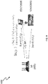
Figures 3 and4 are diagrams of anexemplary wireless network 300 for coordinating transmission between wireless devices grouped based on a received signal strength indicator (RSSI) threshold according to embodiments of the present invention. In the example ofFigure 3 ,AP 305 is associated with wireless devices STA1 (310) and STA2 (315). STA2 may experience desense when receiving data fromwireless AP 305 if STA1 begins transmitting toAP 305. For example,SAT 2 may experience AACI that is magnified when STA1 and STA2 are in close physical proximity and/or are using bands that are close in frequency. Accordingly, to prevent interference between STA1 and STA2, the STAs associated withAP 305 can detect RSSI and report the detected RSSI toAP 305 for identifying potential interference between the STAs. - One example is now described. As depicted in
Figure 3 , STA1 transmits data toAP 305 causing interference that is detected by STA2. STA2 determines if the received interference is from an STA associated with the same AP (i.e. AP 305) as STA2. If the STA is not associated with the same AP (i.e. AP 305) as STA2, the process ends. If STA2 determines that the STA is associated withAP 305, STA2 then determines if the received RSSI from the STA is larger than a predetermined RSSI threshold. As depicted inFigure 4 , if the RSSI received fromSTA 1 is larger than the RSSI threshold, STA2 reports information associated with STA1 ("transmission information") toAP 305. The information reported by STA2 may include the interference source (e.g., STA ID, MAC address, etc.), the band info (e.g., operating frequency), the received RSSI, etc. Because STA1 and STA2 are associated withAP 305 and the received RSSI is above the threshold,AP 305 advantageously groups STA1 and STA2 to coordinate wireless operations and advantageously prevent interference between the devices. -
Figure 5 depicts anexemplary wireless network 500 for coordinating transmission between wireless devices grouped according to RSSI, pathloss (PL), and/or angle of arrival (AOA) according to embodiments of the present invention. In the example ofFigure 5 ,AP 505 groups associated STAs according to metrics measured at the AP-side. For example,AP 505 can measure RSSI when receiving data from STA1 (510), STA2 (515), and STA3 (520) and calculate path loss information according to the transmission power (TxPwr) of an STA indicated in a trigger-based UL packet.AP 505 can also calculate the angle of arrival betweenAP 505 and an STA and estimate the physical proximity of the devices relative to each other according to the PL and the AOA. The AOA can be determined according to channel state information (CSI) of the bands and the antenna pattern ofAP 505, for example. -
AP 505 can group the STAs for coordinating transmissions of the STAs to prevent or mitigate signal interference between the group of STAs based on the metrics measured by the AP. For example, if STA1 and STA2 are determined to be in close physical proximity (e.g., within 3 meters) according to the calculated PL and AOA, STA1 and STA2 can be grouped together byAP 505 to coordinate transmissions between the devices. In the example ofFigure 5 ,AP 505 calculates the PL and AOA associated with STA3 and does not group STA3 with STA1 and STA2 because the PL and AOA information for STA3 are substantially different. -
Figures 6-8 depict anexemplary wireless network 600 for coordinating transmissions between wireless devices grouped according to receiving failures that coincide with the transmission of an associated STA according to embodiments of the present invention.AP 605 can listen over nearby bands (e.g., band 2) while transmitting data to a wireless station overband 1 to determine if the band is busy. As depicted inFigure 6 , STA1 (615) is receiving a transmission fromAP 605 overband 1 while STA2 (610) is transmitting UL data toAP 605 overband 2. Accordingly,AP 605 identifies STA2 a potential source of interference to STA1 if transmissions of the devices transmitted in different directions overlap. - Continuing in
Figure 7 , ifAP 605 does not receive an acknowledgement from STA1 (e.g., a block ack (BA)),AP 605 determines that STA1 and STA2 are likely relatively close to each other (e.g., within 3 meters).AP 605 can group STA1 and STA2 to coordinate transmissions of the devices for preventing or mitigating interference between the devices (e.g., AACI) after any number of receiving errors are detected. - As depicted in
Figure 8 ,AP 605 detects overlapping transmissions. WhenAP 605 subsequently fails to receive a BA from STA2 while STA1 is transmitting, it is considered further evidence that STA1 and STA2 are in close physical proximity. In thiscase AP 605 will typically group STA1 and STA2 for coordinated transmission. -
AP 605 may receive a BA from STA1 or STA2 indicating that some of the data transmitted by STA1 or STA2 was successfully received. In the case of a partial transmission failure,AP 605 can determine that STA1 and STA2 are in close physical proximity according to the BA and group the STAs for coordinated transmission. - After an AP defines groups of associated wireless stations according to estimated physical proximity, the AP can coordinate subsequent transmissions to prevent STAs in the same group from transmitting and receiving at the same time. For example, as depicted in
Figure 9 , AP 905 ofexemplary wireless network 900 can use trigger frame (TR) 920 to solicitUL transmission 925 from the STAs to advantageously avoid simultaneous downlink (DL) and UL transmission within the same group according to embodiments of the present invention. AP 905 does not schedule a packet for transmission to STA2 that would be transmitted while STA1 is transmitting UL data in response to triggerframe 920. In this way, signal interference between STA1 and STA2 is advantageously avoided. -
Figure 10 depicts anexemplary wireless network 1000 including STAs in close proximity to each other that do not understand trigger frames (e.g., legacy devices) according to embodiments of the present invention. AfterAP 1005 groups associated STAs ("STA groups") according to information collected from the STAs (e.g., RSSI), or according to information calculated by the AP (e.g., RSSI, PL, AOA),AP 1005 coordinates transmissions between the STAs and the AP to prevent interference between the STAs. For example, as depicted inFigure 10 ,AP 1005 can avoid scheduling transmissions to STA2 (1015) while receiving UL data from STA1 to advantageously prevent interference between the STAs. -
Figure 11 is a flow chart of an exemplary sequence of computer implemented steps for automatically scheduling transmissions between a wireless access point and its associated wireless devices (STAs) to reduce and/or prevent signal interference between the wireless devices during simultaneous transmission and reception thereof. - At
step 1105, the AP receives or determines transmission information associated with the STAs directly or indirectly. The direct transmission information may include the interference source (e.g., STA ID, MAC address, etc.), the band info (e.g., operating frequency), and/or the received RSSI. The direct transmission information can also be received from an STA associated with the AP and can include information pertaining to another associated STA that is suspected of being in close physical proximity to the reporting STA (e.g., based on RSSI). Indirect transmission information may include the receiving quality (e.g. information indicated in or derived from BA) and traffic patterns (e.g. indication of overlapping transmission and reception).Step 1105 can also include receiving an acknowledgment (e.g., a BA or bitmap) to determine if devices are in close physical proximity according to the successful/unsuccessful transmissions indicated in the acknowledgment. - At
step 1110, the AP assigns groups to associated STAs that are likely to cause signal interference with each other based on the transmission information. For example, associated STAs can be grouped according to their estimated physical proximity with other STAs in the group. According to some embodiments, STAs that are estimated to be within approximately 3 meters are grouped together.Step 1110 can include grouping STAs according to direct information received from the STAs or metrics calculated by the AP, such as PL, AOA, and/or RSSI as well as indirect information, for example. - At
step 1115, the AP schedules transmissions with the STAs so that simultaneous transmission and reception over bands close in frequency within the group of STAs is avoided.Step 1115 includes transmitting trigger frames soliciting uplink transmission from an STA, according to some embodiments. Accordingly, signal interference between STAs within the group is avoided and transmissions between the AP and the STAs are performed efficiently and without reception errors due to desense. -
Figure 12 depicts anexemplary wireless device 1200 upon which embodiments of the present invention can be implemented. Embodiments of the present invention automatically transmit and/or schedule to transmit data between a wireless access point and a group of associated wireless devices (STAs) in a manner that advantageously prevents interference between the devices caused by simultaneous transmission and reception over bands close in frequency (AACI). The following discussion describes one such exemplary electronic system or computer system that can be used as a platform for implementing embodiments of the present invention. Theexemplary computer system 1200 can be a wireless access point or a wireless station, for example. - The
wireless device 1200 includes aprocessor 1205 for running software applications and optionally an operating system.Memory 1210 can include read-only memory and/or random access memory, for example, to store applications and data (e.g., tables of index values) for use by theprocessor 1205 and data received or transmitted bytransceivers wireless device 1200 can include fewer or more transceivers according to some embodiments. Thetransceivers - Embodiments of the present invention are thus described. While the present invention has been described in particular embodiments, it should be appreciated that the present invention should not be construed as limited by such embodiments, but rather construed according to the following claims.
Claims (12)
- A method of transmitting data in a wireless network performed by a wireless access point, in the following also referred to as AP, the method comprising:determining that a first wireless station, in the following also referred to as STA, and a second STA are associated with the AP (1105);creating an STA group by grouping the first STA and the second STA (1110); andcoordinating transmissions of the first STA and the second STA to avoid simultaneous transmission and reception of devices in the STA group (1115).
- The method of Claim 1, further comprising receiving transmission information from the first STA.
- The method of Claim 2, wherein the transmission information comprises a received signal strength indicator, in the following also referred to as RSSI.
- The method of Claim 2 or 3, wherein the first STA transmits the transmission information responsive to determining that the RSSI is above a predetermined threshold.
- The method of any one of Claims 2 to 4, wherein the transmission information comprises: an STA ID; a medium access control, in the following also referred to as MAC, address; band information; and/or an operating frequency.
- The method of any one of Claims 1 to 5, wherein the first STA and the second STAs are operating on bands that are close in frequency.
- The method of any one of Claims 1 to 6, further comprising:measuring a first RSSI of a transmission received from the first STA;calculating first path loss information based on the first RSSI;measuring a second RSSI of a transmission received from the second STA; andcalculating second path loss information based on the second RSSI, wherein the grouping the first STA and the second STA is performed according to the first and second path loss information.
- The method of Claim 7, further comprising:calculating a first angle of arrival of the transmission received from the first STA; andcalculating a second angle of arrival of the transmission received from the second STA, wherein the grouping the first STA and the second STA further is performed according to the angles of arrival.
- The method of any one of Claims 1 to 8, further comprising receiving a block acknowledgment, in the following also referred to as BA, from the first STA, wherein the creating an STA group is performed according to the BA.
- The method of any one of Claims 1 to 9, further comprising determining that the first STA experienced a reception failure while the second STA was transmitting data, and wherein the grouping the first STA and the second STA is performed responsive to the determining that the first STA experienced the reception failure while the second STA was transmitting data.
- A wireless access point, in the following also referred to as AP, comprising:a plurality of wireless transceivers (1220, 1225, 1230); anda processor (1205) configured to perform the method steps as defined in any one of the preceding claims.
- A non-transitory computer-readable storage medium having embedded therein program instructions, which when executed by one or more processors of a device, causes the device to execute a process for coordinating transmissions of wireless stations in a wireless station group, the method comprising the method steps as defined in any one of the preceding claims.
Applications Claiming Priority (2)
| Application Number | Priority Date | Filing Date | Title |
|---|---|---|---|
| US202163150609P | 2021-02-18 | 2021-02-18 | |
| US17/672,417 US12317305B2 (en) | 2021-02-18 | 2022-02-15 | Systems and methods for avoiding interference between wireless devices in a wireless network |
Publications (2)
| Publication Number | Publication Date |
|---|---|
| EP4048022A1 true EP4048022A1 (en) | 2022-08-24 |
| EP4048022B1 EP4048022B1 (en) | 2025-04-02 |
Family
ID=80682542
Family Applications (1)
| Application Number | Title | Priority Date | Filing Date |
|---|---|---|---|
| EP22157243.1A Active EP4048022B1 (en) | 2021-02-18 | 2022-02-17 | Systems and methods for avoiding interference between wireless devices in a wireless network |
Country Status (4)
| Country | Link |
|---|---|
| US (1) | US12317305B2 (en) |
| EP (1) | EP4048022B1 (en) |
| CN (1) | CN114980218B (en) |
| TW (1) | TWI804196B (en) |
Families Citing this family (1)
| Publication number | Priority date | Publication date | Assignee | Title |
|---|---|---|---|---|
| US20240267949A1 (en) * | 2023-02-02 | 2024-08-08 | Meta Platforms Technologies, Llc | Systems and methods for wi-fi packet duration control for in-device coexistence (idc) among asynchronous radios |
Citations (3)
| Publication number | Priority date | Publication date | Assignee | Title |
|---|---|---|---|---|
| US20170019923A1 (en) * | 2015-07-14 | 2017-01-19 | Sony Corporation | Method and apparatus for traffic pattern dependent access coordination to a shared transmission medium |
| WO2018116650A1 (en) * | 2016-12-20 | 2018-06-28 | ソニー株式会社 | Communication device and communication method |
| US20190045522A1 (en) * | 2018-09-18 | 2019-02-07 | Intel IP Corporation | Methods, systems, and apparatus to coordinate multiple access point scheduling and transmission |
Family Cites Families (18)
| Publication number | Priority date | Publication date | Assignee | Title |
|---|---|---|---|---|
| JP5043954B2 (en) * | 2006-11-17 | 2012-10-10 | テレフオンアクチーボラゲット エル エム エリクソン(パブル) | A mobile station communicating with a base station on another uplink when the channel quality parameter falls below a predetermined threshold |
| US7787891B2 (en) * | 2006-12-20 | 2010-08-31 | Intel Corporation | Mobile station localization apparatus, systems, and methods |
| EP2579477B1 (en) | 2010-05-26 | 2017-04-19 | LG Electronics Inc. | Method and apparatus for transceiving data in a wireless lan system |
| US9131395B2 (en) | 2010-09-08 | 2015-09-08 | Broadcom Corporation | Acknowledgment and/or receiver recovery mechanisms for scheduled responses within multiple user, multiple access, and/or MIMO wireless communications |
| CN102740354B (en) | 2011-04-15 | 2015-04-15 | 华为终端有限公司 | Method and device for notifying and obtaining indication information of data to be received |
| US20130182652A1 (en) | 2012-01-13 | 2013-07-18 | Fei Tong | Methods and apparatus in a wireless network |
| US20130301551A1 (en) * | 2012-05-09 | 2013-11-14 | Interdigital Patent Holdings, Inc. | Multi-user multiple input multiple output communications in wireless local area networks and wireless transmit and receive units |
| US9310465B2 (en) | 2012-12-27 | 2016-04-12 | Intel Corporation | Systems and methods for reducing variations in received signal strength indicator (RSSI) measurements for location sensing |
| US9131509B2 (en) | 2013-04-05 | 2015-09-08 | Cambium Networks Limited | Mechanism for group polling without precise timing |
| WO2015006756A1 (en) | 2013-07-12 | 2015-01-15 | Mediatek Singapore Pte. Ltd. | Method of channel access control in wireless local area networks |
| US10149284B2 (en) * | 2015-02-05 | 2018-12-04 | Qualcomm Incorporated | Systems and methods for group block acknowledgment transmissions |
| CN106817202B (en) | 2015-11-30 | 2020-11-06 | 华为技术有限公司 | Random access method and related equipment |
| US10200147B2 (en) * | 2016-04-05 | 2019-02-05 | Intel IP Corporation | Sending feedback in a high efficiency service field |
| US11438188B2 (en) | 2016-09-21 | 2022-09-06 | Apple Inc. | Multicast packets for a wireless local area network |
| CN110945936B (en) | 2017-05-04 | 2023-08-25 | 皇家飞利浦有限公司 | UE group, UE group manager UE and UE group member UE |
| CN111819901B (en) * | 2018-03-08 | 2023-12-01 | 诺基亚技术有限公司 | Method, apparatus and computer readable medium for communication |
| US11411635B2 (en) | 2018-03-19 | 2022-08-09 | Mediatek Singapore Pte. Ltd. | Spatial reuse in WLAN multi-AP network |
| US12342364B2 (en) * | 2018-11-08 | 2025-06-24 | Qualcomm Incorporated | Full-duplex access points |
-
2022
- 2022-02-15 US US17/672,417 patent/US12317305B2/en active Active
- 2022-02-16 CN CN202210142345.5A patent/CN114980218B/en active Active
- 2022-02-17 TW TW111105803A patent/TWI804196B/en active
- 2022-02-17 EP EP22157243.1A patent/EP4048022B1/en active Active
Patent Citations (3)
| Publication number | Priority date | Publication date | Assignee | Title |
|---|---|---|---|---|
| US20170019923A1 (en) * | 2015-07-14 | 2017-01-19 | Sony Corporation | Method and apparatus for traffic pattern dependent access coordination to a shared transmission medium |
| WO2018116650A1 (en) * | 2016-12-20 | 2018-06-28 | ソニー株式会社 | Communication device and communication method |
| US20190045522A1 (en) * | 2018-09-18 | 2019-02-07 | Intel IP Corporation | Methods, systems, and apparatus to coordinate multiple access point scheduling and transmission |
Also Published As
| Publication number | Publication date |
|---|---|
| CN114980218B (en) | 2025-11-07 |
| US20220264592A1 (en) | 2022-08-18 |
| EP4048022B1 (en) | 2025-04-02 |
| US12317305B2 (en) | 2025-05-27 |
| CN114980218A (en) | 2022-08-30 |
| TW202234911A (en) | 2022-09-01 |
| TWI804196B (en) | 2023-06-01 |
Similar Documents
| Publication | Publication Date | Title |
|---|---|---|
| CN113170453B (en) | Reporting beam faults | |
| US11849485B2 (en) | Flexible time masks for listen-before-talk based channel access | |
| CN108289311B (en) | Interference measuring method and device and timing deviation measuring method | |
| US10098137B2 (en) | Unlicensed frequency band with licensed frequency band timing | |
| US11323998B2 (en) | Hidden node detection in LTE licensed assisted access | |
| EP3890216A2 (en) | Apparatus and methods for coordinated spatial reuse in a wireless network | |
| JP2022058855A (en) | Secondary cell beam recovery | |
| US20120157007A1 (en) | Radio station | |
| US12267260B2 (en) | Synchronization signaling block compatible interference coordination patterns to reduce interference in wireless networks | |
| CN102468933A (en) | Method, device and system for feeding back channel state information | |
| CN103391180A (en) | Different communication module sharing method and device in terminal | |
| KR102171775B1 (en) | Link adaptation on license-assisted access carriers | |
| CN116803026A (en) | Repeat scheme for transmission | |
| CN114095997B (en) | Wireless access point configuration method, coordinated space reuse method and related equipment | |
| EP4048022B1 (en) | Systems and methods for avoiding interference between wireless devices in a wireless network | |
| CN119586050A (en) | Selection of coordinate positioning reference signal components |
Legal Events
| Date | Code | Title | Description |
|---|---|---|---|
| PUAI | Public reference made under article 153(3) epc to a published international application that has entered the european phase |
Free format text: ORIGINAL CODE: 0009012 |
|
| STAA | Information on the status of an ep patent application or granted ep patent |
Free format text: STATUS: THE APPLICATION HAS BEEN PUBLISHED |
|
| AK | Designated contracting states |
Kind code of ref document: A1 Designated state(s): AL AT BE BG CH CY CZ DE DK EE ES FI FR GB GR HR HU IE IS IT LI LT LU LV MC MK MT NL NO PL PT RO RS SE SI SK SM TR |
|
| STAA | Information on the status of an ep patent application or granted ep patent |
Free format text: STATUS: REQUEST FOR EXAMINATION WAS MADE |
|
| 17P | Request for examination filed |
Effective date: 20230220 |
|
| RBV | Designated contracting states (corrected) |
Designated state(s): AL AT BE BG CH CY CZ DE DK EE ES FI FR GB GR HR HU IE IS IT LI LT LU LV MC MK MT NL NO PL PT RO RS SE SI SK SM TR |
|
| P01 | Opt-out of the competence of the unified patent court (upc) registered |
Effective date: 20230627 |
|
| GRAP | Despatch of communication of intention to grant a patent |
Free format text: ORIGINAL CODE: EPIDOSNIGR1 |
|
| STAA | Information on the status of an ep patent application or granted ep patent |
Free format text: STATUS: GRANT OF PATENT IS INTENDED |
|
| RIC1 | Information provided on ipc code assigned before grant |
Ipc: H04W 72/121 20230101ALN20240828BHEP Ipc: H04W 72/542 20230101ALI20240828BHEP Ipc: H04W 84/12 20090101AFI20240828BHEP |
|
| INTG | Intention to grant announced |
Effective date: 20240909 |
|
| GRAS | Grant fee paid |
Free format text: ORIGINAL CODE: EPIDOSNIGR3 |
|
| GRAA | (expected) grant |
Free format text: ORIGINAL CODE: 0009210 |
|
| STAA | Information on the status of an ep patent application or granted ep patent |
Free format text: STATUS: THE PATENT HAS BEEN GRANTED |
|
| AK | Designated contracting states |
Kind code of ref document: B1 Designated state(s): AL AT BE BG CH CY CZ DE DK EE ES FI FR GB GR HR HU IE IS IT LI LT LU LV MC MK MT NL NO PL PT RO RS SE SI SK SM TR |
|
| REG | Reference to a national code |
Ref country code: GB Ref legal event code: FG4D |
|
| REG | Reference to a national code |
Ref country code: CH Ref legal event code: EP |
|
| REG | Reference to a national code |
Ref country code: IE Ref legal event code: FG4D |
|
| REG | Reference to a national code |
Ref country code: DE Ref legal event code: R096 Ref document number: 602022012430 Country of ref document: DE |
|
| REG | Reference to a national code |
Ref country code: NL Ref legal event code: MP Effective date: 20250402 |
|
| PG25 | Lapsed in a contracting state [announced via postgrant information from national office to epo] |
Ref country code: NL Free format text: LAPSE BECAUSE OF FAILURE TO SUBMIT A TRANSLATION OF THE DESCRIPTION OR TO PAY THE FEE WITHIN THE PRESCRIBED TIME-LIMIT Effective date: 20250402 |
|
| REG | Reference to a national code |
Ref country code: AT Ref legal event code: MK05 Ref document number: 1782575 Country of ref document: AT Kind code of ref document: T Effective date: 20250402 |
|
| PG25 | Lapsed in a contracting state [announced via postgrant information from national office to epo] |
Ref country code: FI Free format text: LAPSE BECAUSE OF FAILURE TO SUBMIT A TRANSLATION OF THE DESCRIPTION OR TO PAY THE FEE WITHIN THE PRESCRIBED TIME-LIMIT Effective date: 20250402 Ref country code: ES Free format text: LAPSE BECAUSE OF FAILURE TO SUBMIT A TRANSLATION OF THE DESCRIPTION OR TO PAY THE FEE WITHIN THE PRESCRIBED TIME-LIMIT Effective date: 20250402 Ref country code: PT Free format text: LAPSE BECAUSE OF FAILURE TO SUBMIT A TRANSLATION OF THE DESCRIPTION OR TO PAY THE FEE WITHIN THE PRESCRIBED TIME-LIMIT Effective date: 20250804 |
|
| REG | Reference to a national code |
Ref country code: LT Ref legal event code: MG9D |
|
| PG25 | Lapsed in a contracting state [announced via postgrant information from national office to epo] |
Ref country code: NO Free format text: LAPSE BECAUSE OF FAILURE TO SUBMIT A TRANSLATION OF THE DESCRIPTION OR TO PAY THE FEE WITHIN THE PRESCRIBED TIME-LIMIT Effective date: 20250702 Ref country code: GR Free format text: LAPSE BECAUSE OF FAILURE TO SUBMIT A TRANSLATION OF THE DESCRIPTION OR TO PAY THE FEE WITHIN THE PRESCRIBED TIME-LIMIT Effective date: 20250703 |
|
| PG25 | Lapsed in a contracting state [announced via postgrant information from national office to epo] |
Ref country code: PL Free format text: LAPSE BECAUSE OF FAILURE TO SUBMIT A TRANSLATION OF THE DESCRIPTION OR TO PAY THE FEE WITHIN THE PRESCRIBED TIME-LIMIT Effective date: 20250402 |
|
| PG25 | Lapsed in a contracting state [announced via postgrant information from national office to epo] |
Ref country code: BG Free format text: LAPSE BECAUSE OF FAILURE TO SUBMIT A TRANSLATION OF THE DESCRIPTION OR TO PAY THE FEE WITHIN THE PRESCRIBED TIME-LIMIT Effective date: 20250402 |
|
| PG25 | Lapsed in a contracting state [announced via postgrant information from national office to epo] |
Ref country code: HR Free format text: LAPSE BECAUSE OF FAILURE TO SUBMIT A TRANSLATION OF THE DESCRIPTION OR TO PAY THE FEE WITHIN THE PRESCRIBED TIME-LIMIT Effective date: 20250402 |
|
| PG25 | Lapsed in a contracting state [announced via postgrant information from national office to epo] |
Ref country code: AT Free format text: LAPSE BECAUSE OF FAILURE TO SUBMIT A TRANSLATION OF THE DESCRIPTION OR TO PAY THE FEE WITHIN THE PRESCRIBED TIME-LIMIT Effective date: 20250402 |
|
| PG25 | Lapsed in a contracting state [announced via postgrant information from national office to epo] |
Ref country code: RS Free format text: LAPSE BECAUSE OF FAILURE TO SUBMIT A TRANSLATION OF THE DESCRIPTION OR TO PAY THE FEE WITHIN THE PRESCRIBED TIME-LIMIT Effective date: 20250702 |
|
| PG25 | Lapsed in a contracting state [announced via postgrant information from national office to epo] |
Ref country code: IS Free format text: LAPSE BECAUSE OF FAILURE TO SUBMIT A TRANSLATION OF THE DESCRIPTION OR TO PAY THE FEE WITHIN THE PRESCRIBED TIME-LIMIT Effective date: 20250802 |
|
| PG25 | Lapsed in a contracting state [announced via postgrant information from national office to epo] |
Ref country code: LV Free format text: LAPSE BECAUSE OF FAILURE TO SUBMIT A TRANSLATION OF THE DESCRIPTION OR TO PAY THE FEE WITHIN THE PRESCRIBED TIME-LIMIT Effective date: 20250402 |
|
| REG | Reference to a national code |
Ref country code: DE Ref legal event code: R097 Ref document number: 602022012430 Country of ref document: DE |
|
| PG25 | Lapsed in a contracting state [announced via postgrant information from national office to epo] |
Ref country code: SM Free format text: LAPSE BECAUSE OF FAILURE TO SUBMIT A TRANSLATION OF THE DESCRIPTION OR TO PAY THE FEE WITHIN THE PRESCRIBED TIME-LIMIT Effective date: 20250402 Ref country code: DK Free format text: LAPSE BECAUSE OF FAILURE TO SUBMIT A TRANSLATION OF THE DESCRIPTION OR TO PAY THE FEE WITHIN THE PRESCRIBED TIME-LIMIT Effective date: 20250402 |
|
| PGFP | Annual fee paid to national office [announced via postgrant information from national office to epo] |
Ref country code: FR Payment date: 20251208 Year of fee payment: 5 |
|
| PG25 | Lapsed in a contracting state [announced via postgrant information from national office to epo] |
Ref country code: CZ Free format text: LAPSE BECAUSE OF FAILURE TO SUBMIT A TRANSLATION OF THE DESCRIPTION OR TO PAY THE FEE WITHIN THE PRESCRIBED TIME-LIMIT Effective date: 20250402 |
|
| PG25 | Lapsed in a contracting state [announced via postgrant information from national office to epo] |
Ref country code: EE Free format text: LAPSE BECAUSE OF FAILURE TO SUBMIT A TRANSLATION OF THE DESCRIPTION OR TO PAY THE FEE WITHIN THE PRESCRIBED TIME-LIMIT Effective date: 20250402 |
|
| PG25 | Lapsed in a contracting state [announced via postgrant information from national office to epo] |
Ref country code: SK Free format text: LAPSE BECAUSE OF FAILURE TO SUBMIT A TRANSLATION OF THE DESCRIPTION OR TO PAY THE FEE WITHIN THE PRESCRIBED TIME-LIMIT Effective date: 20250402 |
|
| PG25 | Lapsed in a contracting state [announced via postgrant information from national office to epo] |
Ref country code: IT Free format text: LAPSE BECAUSE OF FAILURE TO SUBMIT A TRANSLATION OF THE DESCRIPTION OR TO PAY THE FEE WITHIN THE PRESCRIBED TIME-LIMIT Effective date: 20250402 |
|
| PLBE | No opposition filed within time limit |
Free format text: ORIGINAL CODE: 0009261 |
|
| STAA | Information on the status of an ep patent application or granted ep patent |
Free format text: STATUS: NO OPPOSITION FILED WITHIN TIME LIMIT |
|
| REG | Reference to a national code |
Ref country code: CH Ref legal event code: L10 Free format text: ST27 STATUS EVENT CODE: U-0-0-L10-L00 (AS PROVIDED BY THE NATIONAL OFFICE) Effective date: 20260211 |
|
| 26N | No opposition filed |
Effective date: 20260105 |
|
| PGFP | Annual fee paid to national office [announced via postgrant information from national office to epo] |
Ref country code: GB Payment date: 20260106 Year of fee payment: 5 |
|
| PGFP | Annual fee paid to national office [announced via postgrant information from national office to epo] |
Ref country code: DE Payment date: 20251224 Year of fee payment: 5 |