EP4047919B1 - In-vehicle sensor system, and data generation method for in-vehicle sensor system - Google Patents
In-vehicle sensor system, and data generation method for in-vehicle sensor system Download PDFInfo
- Publication number
- EP4047919B1 EP4047919B1 EP22154646.8A EP22154646A EP4047919B1 EP 4047919 B1 EP4047919 B1 EP 4047919B1 EP 22154646 A EP22154646 A EP 22154646A EP 4047919 B1 EP4047919 B1 EP 4047919B1
- Authority
- EP
- European Patent Office
- Prior art keywords
- data
- casing
- detector
- vehicle
- respect
- Prior art date
- Legal status (The legal status is an assumption and is not a legal conclusion. Google has not performed a legal analysis and makes no representation as to the accuracy of the status listed.)
- Active
Links
Images


Classifications
-
- G—PHYSICS
- G06—COMPUTING OR CALCULATING; COUNTING
- G06V—IMAGE OR VIDEO RECOGNITION OR UNDERSTANDING
- G06V20/00—Scenes; Scene-specific elements
- G06V20/50—Context or environment of the image
- G06V20/56—Context or environment of the image exterior to a vehicle by using sensors mounted on the vehicle
- G06V20/58—Recognition of moving objects or obstacles, e.g. vehicles or pedestrians; Recognition of traffic objects, e.g. traffic signs, traffic lights or roads
-
- H—ELECTRICITY
- H04—ELECTRIC COMMUNICATION TECHNIQUE
- H04N—PICTORIAL COMMUNICATION, e.g. TELEVISION
- H04N17/00—Diagnosis, testing or measuring for television systems or their details
- H04N17/002—Diagnosis, testing or measuring for television systems or their details for television cameras
-
- B—PERFORMING OPERATIONS; TRANSPORTING
- B60—VEHICLES IN GENERAL
- B60R—VEHICLES, VEHICLE FITTINGS, OR VEHICLE PARTS, NOT OTHERWISE PROVIDED FOR
- B60R11/00—Arrangements for holding or mounting articles, not otherwise provided for
- B60R11/04—Mounting of cameras operative during drive; Arrangement of controls thereof relative to the vehicle
-
- B—PERFORMING OPERATIONS; TRANSPORTING
- B60—VEHICLES IN GENERAL
- B60W—CONJOINT CONTROL OF VEHICLE SUB-UNITS OF DIFFERENT TYPE OR DIFFERENT FUNCTION; CONTROL SYSTEMS SPECIALLY ADAPTED FOR HYBRID VEHICLES; ROAD VEHICLE DRIVE CONTROL SYSTEMS FOR PURPOSES NOT RELATED TO THE CONTROL OF A PARTICULAR SUB-UNIT
- B60W50/00—Details of control systems for road vehicle drive control not related to the control of a particular sub-unit, e.g. process diagnostic or vehicle driver interfaces
- B60W50/08—Interaction between the driver and the control system
- B60W50/10—Interpretation of driver requests or demands
-
- H—ELECTRICITY
- H04—ELECTRIC COMMUNICATION TECHNIQUE
- H04N—PICTORIAL COMMUNICATION, e.g. TELEVISION
- H04N23/00—Cameras or camera modules comprising electronic image sensors; Control thereof
- H04N23/50—Constructional details
-
- H—ELECTRICITY
- H04—ELECTRIC COMMUNICATION TECHNIQUE
- H04N—PICTORIAL COMMUNICATION, e.g. TELEVISION
- H04N23/00—Cameras or camera modules comprising electronic image sensors; Control thereof
- H04N23/57—Mechanical or electrical details of cameras or camera modules specially adapted for being embedded in other devices
-
- H—ELECTRICITY
- H04—ELECTRIC COMMUNICATION TECHNIQUE
- H04N—PICTORIAL COMMUNICATION, e.g. TELEVISION
- H04N23/00—Cameras or camera modules comprising electronic image sensors; Control thereof
- H04N23/60—Control of cameras or camera modules
- H04N23/695—Control of camera direction for changing a field of view, e.g. pan, tilt or based on tracking of objects
-
- H—ELECTRICITY
- H04—ELECTRIC COMMUNICATION TECHNIQUE
- H04N—PICTORIAL COMMUNICATION, e.g. TELEVISION
- H04N23/00—Cameras or camera modules comprising electronic image sensors; Control thereof
- H04N23/80—Camera processing pipelines; Components thereof
-
- H—ELECTRICITY
- H04—ELECTRIC COMMUNICATION TECHNIQUE
- H04N—PICTORIAL COMMUNICATION, e.g. TELEVISION
- H04N5/00—Details of television systems
- H04N5/76—Television signal recording
-
- H—ELECTRICITY
- H04—ELECTRIC COMMUNICATION TECHNIQUE
- H04N—PICTORIAL COMMUNICATION, e.g. TELEVISION
- H04N7/00—Television systems
- H04N7/18—Closed-circuit television [CCTV] systems, i.e. systems in which the video signal is not broadcast
-
- B—PERFORMING OPERATIONS; TRANSPORTING
- B60—VEHICLES IN GENERAL
- B60R—VEHICLES, VEHICLE FITTINGS, OR VEHICLE PARTS, NOT OTHERWISE PROVIDED FOR
- B60R11/00—Arrangements for holding or mounting articles, not otherwise provided for
- B60R2011/0001—Arrangements for holding or mounting articles, not otherwise provided for characterised by position
- B60R2011/0003—Arrangements for holding or mounting articles, not otherwise provided for characterised by position inside the vehicle
- B60R2011/0026—Windows, e.g. windscreen
-
- B—PERFORMING OPERATIONS; TRANSPORTING
- B60—VEHICLES IN GENERAL
- B60W—CONJOINT CONTROL OF VEHICLE SUB-UNITS OF DIFFERENT TYPE OR DIFFERENT FUNCTION; CONTROL SYSTEMS SPECIALLY ADAPTED FOR HYBRID VEHICLES; ROAD VEHICLE DRIVE CONTROL SYSTEMS FOR PURPOSES NOT RELATED TO THE CONTROL OF A PARTICULAR SUB-UNIT
- B60W2420/00—Indexing codes relating to the type of sensors based on the principle of their operation
- B60W2420/40—Photo, light or radio wave sensitive means, e.g. infrared sensors
- B60W2420/408—Radar; Laser, e.g. lidar
-
- B—PERFORMING OPERATIONS; TRANSPORTING
- B60—VEHICLES IN GENERAL
- B60W—CONJOINT CONTROL OF VEHICLE SUB-UNITS OF DIFFERENT TYPE OR DIFFERENT FUNCTION; CONTROL SYSTEMS SPECIALLY ADAPTED FOR HYBRID VEHICLES; ROAD VEHICLE DRIVE CONTROL SYSTEMS FOR PURPOSES NOT RELATED TO THE CONTROL OF A PARTICULAR SUB-UNIT
- B60W2422/00—Indexing codes relating to the special location or mounting of sensors
-
- H—ELECTRICITY
- H04—ELECTRIC COMMUNICATION TECHNIQUE
- H04L—TRANSMISSION OF DIGITAL INFORMATION, e.g. TELEGRAPHIC COMMUNICATION
- H04L12/00—Data switching networks
- H04L12/28—Data switching networks characterised by path configuration, e.g. LAN [Local Area Networks] or WAN [Wide Area Networks]
- H04L12/40—Bus networks
- H04L2012/40208—Bus networks characterized by the use of a particular bus standard
- H04L2012/40215—Controller Area Network CAN
Definitions
- the present invention relates to an in-vehicle sensor system for outputting detection data representing a situation within a detection range around a vehicle, for example, a target object and lane markings around the vehicle, and a data generation method to be applied to an in-vehicle sensor system.
- an in-vehicle sensor system for detecting a target object around an own vehicle, and outputting data representing results of the detection (see Japanese Patent Application Laid-open No. 2020-131818 ).
- the data output from the in-vehicle sensor system is supplied to a driving assistance apparatus of the vehicle.
- the driving assistance apparatus recognizes a situation around the vehicle (for example, a positional relationship between the vehicle and the target object) based on the data supplied from the in-vehicle sensor system and executes driving assistance in accordance with results of the recognition.
- the related-art apparatus includes a surrounding sensor (for example, a camera sensor).
- the surrounding sensor is fixed to a predetermined part of a vehicle body.
- the surrounding sensor includes a detector (for example, an image pickup unit including a lens and an image sensor) and a controller (for example, an image processor).
- the detector detects a target object within a detection range determined through use of, as a reference, an axis extending in a predetermined direction from a predetermined point (for example, a center portion of the lens) of the surrounding sensor, and outputs detection data (hereinafter referred to as "original data") representing results of the detection.
- the driving assistance apparatus (control program for the driving assistance apparatus) is designed based on the premise that the driving assistance apparatus is supplied with data acquired under a state in which a position and a posture of the detector of the surrounding sensor mounted to the vehicle body match a normal position and a normal posture of the detector. Accordingly, in a case in which any one or both of the position and the posture of the detector of the surrounding sensor differ from the normal position and the normal posture, when the detection data of the detector is used as it is, the driving assistance apparatus cannot accurately recognize the situation around the vehicle.
- the related-art apparatus is configured as described below.
- the surrounding sensor is mounted to a bracket fixed to a predetermined part of the vehicle body.
- the work of mounting the bracket to the vehicle body causes errors of a position and a posture of the bracket. That is, the position and the posture of the bracket on the vehicle body vary depending on each vehicle.
- the position and the posture of the surrounding sensor mounted to the bracket also vary depending on each vehicle. Accordingly, when the surrounding sensor is mounted to the bracket during the production of the vehicle, the sensor calibration is always required.
- a controller of a surrounding sensor after the replacement reads out the adjustment values measured at the time of production of the vehicle and stored in the storage device. Then, the controller corrects the original data based on the read-out adjustment values.
- the sensor calibration is not required to be performed.
- the surrounding sensor of the related-art apparatus includes a casing for supporting (accommodating) the detector. This casing is mounted to the bracket.
- the related-art apparatus is based on the premise that a mounting error of the casing to the bracket is "0". That is, in the related-art apparatus, it is regarded that the position and the posture of the casing before the replacement with respect to the bracket (vehicle body) are substantially the same as the position and the posture of the casing after the replacement with respect to the bracket (vehicle body).
- the related-art apparatus is based on the premise that a mounting error of the detector to the casing is "0".
- the position and the posture of the detector with respect to the casing of the surrounding sensor before the replacement are the same as "the position and the posture of the detector with respect to the casing of the surrounding sensor after the replacement.”
- appropriate (effective) data can be obtained when the controller of the surrounding sensor after the replacement corrects the original data based on the adjustment values read out from the storage device.
- the mounting error of the detector to the casing is caused. That is, in some cases, "the position and the posture of the detector with respect to the casing of the surrounding sensor before the replacement" differ from “the position and the posture of the detector with respect to the casing of the surrounding sensor after the replacement.” In those cases, even when the controller of the surrounding sensor after the replacement corrects the original data based on the adjustment values read out from the storage device, appropriate data cannot be obtained.
- US 2013/222607 A1 relates to a camera device, a camera system and a camera calibration method for calibration of an angle of a camera mounted on a movable object.
- CN 105 376 564 A discloses a camera calibration equipment.
- an in-vehicle sensor system according to claim 1.
- the second data is determined and stored in the second storage at a vehicle production factory or a vehicle repair and maintenance shop. After that, in some cases, the surrounding sensor of the vehicle fails, and replacement of the surrounding sensor is required. In those cases, a worker removes the failed surrounding sensor from the bracket and mounts a new surrounding sensor to the bracket. That is, in this case, the bracket is not replaced, and is still fixed to the vehicle body.
- the second storage is also not replaced.
- the surrounding sensor fails, a new surrounding sensor is mounted to the existing (common) bracket, and hence the position and the posture of the casing with respect to the vehicle body (that is, the second data) do not change before and after the replacement of the surrounding sensor.
- the corrector may read out the second data from the second storage and use the second data for the correction of the detection data without a problem.
- the corrector corrects the detection data based on the first data specific to the surrounding sensor before the replacement and on the second data independent of the individual surrounding sensor (that is, common to the surrounding sensors before and after the replacement). After the surrounding sensor is replaced, the corrector corrects the detection data based on the first data specific to the surrounding sensor after the replacement and on the second data independent of the individual surrounding sensor. That is, the first data specific to the current surrounding sensor is always reflected in the correction result of the detection data.
- the work of storing the second data into the second storage is simplified as compared to a case in which the deviation amount of the actual position and the actual posture of the casing with respect to the vehicle body from the predetermined normal design position and the predetermined normal design posture of the casing with respect to the vehicle body is calculated based on the first data and the third data, and a result of the calculation is stored in the second storage as the second data.
- the second storage is an area of a part of a storage area of a storage device included in an in-vehicle component which is provided separately from the surrounding sensor.
- the present invention also encompasses a detection data generation method to be applied to an in-vehicle sensor system according to claim 5.
- An in-vehicle camera system (in-vehicle sensor system) 1 includes, as illustrated in FIG. 1 , an image pickup apparatus 10 and an external apparatus 20.
- the in-vehicle camera system 1 is connected to a driving assistance apparatus DA via a network CAN. As described later, the in-vehicle camera system 1 corrects image data representing an image obtained by photographing a front view of a vehicle, and supplies the corrected image data to the driving assistance apparatus DA via the network CAN.
- the driving assistance apparatus DA executes various types of driving assistance based on the image data supplied from the in-vehicle camera system 1.
- Step 703 the CPU obtains the third error E3 based on the first error E1 and the second error E2, and determines, based on this third error E3, an image conversion parameter (image conversion matrix component) for converting (correcting) the original image data into the corrected image data.
- an image conversion parameter image conversion matrix component
- Step 705 the CPU corrects the acquired original image data through use of the image conversion parameter to generate the corrected image data (normal image data), and supplies the corrected image data to the driving assistance ECU.
- Step 713 The CPU transmits the obtained second error E2 to the external apparatus 20 via the network CAN, and stores the second error E2 into the second storage 21.
- Step 710 to Step 713 may be executed while the specific computer apparatus performs data exchange with the image processor 13.
- Step 701 After the vehicle is shipped from the production factory, when the image pickup apparatus 10 is normal, the CPU executes the processing steps of from Step 701 to Step 703 at the time of activation, and then repeats the processing steps of Step 704 and Step 705.
- the first error E1 specific to the image pickup apparatus 10 mounted to the vehicle body B at the current time point is reflected in the image conversion parameter.
- the corrected image data having the same level of precision before and after the replacement of the image pickup apparatus 10 can be transmitted from the image pickup apparatus 10 to the driving assistance apparatus DA.
- the first error E1 is stored in the first storage 14, but in place of the first error E1, a first adjustment value being a value corresponding to the first error E1 and for use to correct the mounting error of the detector 12 to the casing 11 may be stored in the first storage 14.
- the first adjustment value be determined by a jig (measurement apparatus) for measuring the first error E1 at the time of production of the image pickup apparatus 10, the image processor 13, or the like.
- a second adjustment value being a value corresponding to the second error E2 and for use to correct the mounting error of the bracket BC to the vehicle body be stored in the second storage 21.
- the image processor 13 is provided inside of the casing 11, but as another example, as illustrated in FIG. 8 , the image processor 13 may be provided outside of the casing 11. That is, in this example, the image processor 13 is connected to the detector 12 and the first storage 14 and to the second storage 21 via the network CAN. The image processor 13 acquires the original image data, the first error E1, and the second error E2 from the detector 12, the first storage 14, and the second storage 21, respectively. Then, the image processor 13 corrects the original image data based on the first error E1 and the second error E2, and supplies the corrected image data to the driving assistance apparatus DA. In this case, the image processor 13 may be incorporated in another apparatus, for example, the external apparatus 20 or the driving assistance apparatus DA.
- the second error E2 is stored in the external apparatus 20, but the second error E2 may be stored in a storage device of "the driving assistance apparatus DA, an engine control apparatus, or a brake control apparatus" serving as the external apparatus 20. That is, a part of a storage area of a storage device of another in-vehicle component may be used as the external apparatus 20. In this case, it is preferred that the another in-vehicle component be a component that has a low possibility of replacement.
- the present invention is also applicable to another surrounding monitoring sensor system other than the in-vehicle camera system 1.
- the present invention is also applicable to a radar sensor system.
- the radar sensor system includes a radar apparatus and an external apparatus.
- the radar apparatus includes a detector, a controller, a first storage, and a casing.
- the detector includes a transmitter for transmitting radar waves, and a receiver for receiving reflected waves.
- a deviation amount (first error E1) of "an actual position and an actual posture" of the detector with respect to the casing from "a normal position and a normal posture" of the detector with respect to the casing is stored in the first storage included in the radar apparatus.
- the casing is fixed to a bracket fixed with respect to the vehicle body.
- a deviation amount (third error E3) of "an actual position and an actual posture” of the detector of the radar apparatus with respect to the vehicle body from “a normal position and a normal posture” of the detector of the radar apparatus with respect to the vehicle body is measured.
- a deviation amount (second error E2) of "an actual position and an actual posture” of the casing with respect to the vehicle body from "a normal position and a normal posture” of the casing with respect to the vehicle body is obtained from the third error E3 and the first error E1 stored in the first storage included in the radar apparatus, and the deviation amount (second error E2) is stored in the second storage of the external apparatus.
- the controller reads out the first error E1 and the second error E2 from the first storage and the second storage, respectively, corrects data output from the detector ("distance and direction from the vehicle" of the target object around the vehicle) based on the first error E1 and the second error E2, and transmits the corrected data to the driving assistance apparatus.
- the casing 11 of the image pickup apparatus 10 and the bracket BC may be shaped as illustrated in FIG. 9 .
- the bracket BC includes adhesion portions Ad at a plurality of upper portions.
- the adhesion portions Ad are caused to adhere to the front windshield glass G with an adhesive so that the bracket BC is fixed to the front windshield glass G.
- the casing 11 is mounted to the bracket BC from below, and is fixed to the bracket BC by a fixing unit (not shown).
- the first error E1 includes "the error of the position of the detector 12 with respect to the casing 11 and the error of the posture of the detector 12 with respect to the casing 11" in a case in which it is assumed that the casing 11 is mounted at a normal position and in a normal posture with respect to the vehicle body B.
- the first error E1 is not only required to be a value obtained in a case in which it is assumed that the casing 11 is mounted at a normal position and in a normal posture with respect to the vehicle body B.
- the CPU may convert the first error E1 into "an error in a case in which it is assumed that the casing 11 is mounted at a normal position and in a normal posture with respect to the vehicle body B," and then may obtain the second error E2.
Landscapes
- Engineering & Computer Science (AREA)
- Multimedia (AREA)
- Signal Processing (AREA)
- Automation & Control Theory (AREA)
- Mechanical Engineering (AREA)
- Transportation (AREA)
- Physics & Mathematics (AREA)
- General Physics & Mathematics (AREA)
- Theoretical Computer Science (AREA)
- Human Computer Interaction (AREA)
- General Health & Medical Sciences (AREA)
- Biomedical Technology (AREA)
- Health & Medical Sciences (AREA)
- Length Measuring Devices By Optical Means (AREA)
- Studio Devices (AREA)
- Radar Systems Or Details Thereof (AREA)
Description
- The present invention relates to an in-vehicle sensor system for outputting detection data representing a situation within a detection range around a vehicle, for example, a target object and lane markings around the vehicle, and a data generation method to be applied to an in-vehicle sensor system.
- Hitherto, there has been known an in-vehicle sensor system (hereinafter referred to as "related-art apparatus") for detecting a target object around an own vehicle, and outputting data representing results of the detection (see
Japanese Patent Application Laid-open No. 2020-131818 - The related-art apparatus includes a surrounding sensor (for example, a camera sensor). The surrounding sensor is fixed to a predetermined part of a vehicle body. The surrounding sensor includes a detector (for example, an image pickup unit including a lens and an image sensor) and a controller (for example, an image processor). The detector detects a target object within a detection range determined through use of, as a reference, an axis extending in a predetermined direction from a predetermined point (for example, a center portion of the lens) of the surrounding sensor, and outputs detection data (hereinafter referred to as "original data") representing results of the detection.
- In general, the driving assistance apparatus (control program for the driving assistance apparatus) is designed based on the premise that the driving assistance apparatus is supplied with data acquired under a state in which a position and a posture of the detector of the surrounding sensor mounted to the vehicle body match a normal position and a normal posture of the detector. Accordingly, in a case in which any one or both of the position and the posture of the detector of the surrounding sensor differ from the normal position and the normal posture, when the detection data of the detector is used as it is, the driving assistance apparatus cannot accurately recognize the situation around the vehicle. In view of the above, the related-art apparatus is configured as described below.
- First, at a vehicle production factory, under a state in which the surrounding sensor is fixed to the vehicle, amounts of difference of a current position and a current posture of the surrounding sensor from a normal position and a normal posture of the surrounding sensor are measured through use of a predetermined jig (target board). Then, adjustment values corresponding to results of the measurement are stored in a storage device provided separately from the surrounding sensor. This work is hereinafter referred to as "sensor calibration." After the sensor calibration is ended, the controller corrects the original data based on the adjustment values stored in the storage device, generates data expected to be obtained when the position and the posture of the surrounding sensor match the normal position and the normal posture, and supplies the data to the driving assistance apparatus.
- Incidentally, the surrounding sensor is mounted to a bracket fixed to a predetermined part of the vehicle body. The work of mounting the bracket to the vehicle body causes errors of a position and a posture of the bracket. That is, the position and the posture of the bracket on the vehicle body vary depending on each vehicle. Thus, the position and the posture of the surrounding sensor mounted to the bracket also vary depending on each vehicle. Accordingly, when the surrounding sensor is mounted to the bracket during the production of the vehicle, the sensor calibration is always required.
- When the surrounding sensor fails and is replaced after the vehicle is shipped from the production factory, a controller of a surrounding sensor after the replacement reads out the adjustment values measured at the time of production of the vehicle and stored in the storage device. Then, the controller corrects the original data based on the read-out adjustment values. As described above, according to the related-art apparatus, when the surrounding sensor is replaced, the sensor calibration is not required to be performed.
- The surrounding sensor of the related-art apparatus includes a casing for supporting (accommodating) the detector. This casing is mounted to the bracket. The related-art apparatus is based on the premise that a mounting error of the casing to the bracket is "0". That is, in the related-art apparatus, it is regarded that the position and the posture of the casing before the replacement with respect to the bracket (vehicle body) are substantially the same as the position and the posture of the casing after the replacement with respect to the bracket (vehicle body). In addition, the related-art apparatus is based on the premise that a mounting error of the detector to the casing is "0". That is, it is regarded that "the position and the posture of the detector with respect to the casing of the surrounding sensor before the replacement" are the same as "the position and the posture of the detector with respect to the casing of the surrounding sensor after the replacement." In a case in which the above-mentioned conditions are satisfied, appropriate (effective) data can be obtained when the controller of the surrounding sensor after the replacement corrects the original data based on the adjustment values read out from the storage device.
- However, in general, in a step of producing the surrounding sensor, the mounting error of the detector to the casing is caused. That is, in some cases, "the position and the posture of the detector with respect to the casing of the surrounding sensor before the replacement" differ from "the position and the posture of the detector with respect to the casing of the surrounding sensor after the replacement." In those cases, even when the controller of the surrounding sensor after the replacement corrects the original data based on the adjustment values read out from the storage device, appropriate data cannot be obtained. That is, the data obtained through correction of the original data contains an error corresponding to differences between "the position and the posture of the detector with respect to the casing of the surrounding sensor before the replacement" and "the position and the posture of the detector with respect to the casing of the surrounding sensor after the replacement." Thus, there is a fear in that, when the surrounding sensor is replaced, a precision (accuracy) of data (corrected detection data) supplied from this in-vehicle sensor system to the driving assistance apparatus is decreased as compared to a precision (accuracy) of data (corrected detection data) supplied from the surrounding sensor before the replacement to the driving assistance apparatus.
-
US 2013/222607 A1 relates to a camera device, a camera system and a camera calibration method for calibration of an angle of a camera mounted on a movable object. -
CN 105 376 564 A discloses a camera calibration equipment. -
US 2020/265242 A1 discloses a vehicle driving assist apparatus for executing a driving assist control, based on surrounding information provided by at least one surrounding sensor for detecting surrounding situation around an own vehicle. - The present invention has an object to provide an in-vehicle sensor system capable of maintaining an equivalent level of precision (accuracy) of data to be output before and after replacement of a surrounding sensor.
- In order to solve the above-mentioned problem, according to at least one embodiment of the present invention, there is provided an in-vehicle sensor system according to claim 1.
- In the in-vehicle sensor system configured as described above, the second data is determined and stored in the second storage at a vehicle production factory or a vehicle repair and maintenance shop. After that, in some cases, the surrounding sensor of the vehicle fails, and replacement of the surrounding sensor is required. In those cases, a worker removes the failed surrounding sensor from the bracket and mounts a new surrounding sensor to the bracket. That is, in this case, the bracket is not replaced, and is still fixed to the vehicle body. The second storage is also not replaced. As described above, when the surrounding sensor fails, a new surrounding sensor is mounted to the existing (common) bracket, and hence the position and the posture of the casing with respect to the vehicle body (that is, the second data) do not change before and after the replacement of the surrounding sensor. Thus, when the surrounding sensor is replaced, the corrector may read out the second data from the second storage and use the second data for the correction of the detection data without a problem.
- Before the surrounding sensor is replaced, the corrector corrects the detection data based on the first data specific to the surrounding sensor before the replacement and on the second data independent of the individual surrounding sensor (that is, common to the surrounding sensors before and after the replacement). After the surrounding sensor is replaced, the corrector corrects the detection data based on the first data specific to the surrounding sensor after the replacement and on the second data independent of the individual surrounding sensor. That is, the first data specific to the current surrounding sensor is always reflected in the correction result of the detection data. Thus, according to the at least one embodiment of the present invention, when the surrounding sensor is replaced, without measurement of the position and the posture of the detector of the surrounding sensor after the replacement, it is possible to maintain, at an equivalent level, the precision (accuracy) of the data to be output from the surrounding sensor before the replacement and the precision (accuracy) of the data to be output from the surrounding sensor after the replacement.
- In the in-vehicle sensor system according to one aspect of the present invention, the second storage is configured to store, as the second data, data directly representing the deviation amount of the actual position and the actual posture of the casing with respect to the vehicle body from the predetermined normal design position and the predetermined normal design posture of the casing with respect to the vehicle body.
- With this configuration, after the surrounding sensor is replaced, the corrector is not required to perform calculation for obtaining the deviation amount of the casing. That is, the corrector can correct the detection data through direct use of the first data and the second data.
- In the in-vehicle sensor system according to another aspect of the present invention, the second storage is configured to store, as the second data, data of a combination of: third data directly representing a deviation amount of an actual position and an actual posture of the detector with respect to the vehicle body from a predetermined normal design position and a predetermined normal design posture of the detector with respect to the vehicle body; and first data directly representing the deviation amount of the actual position and the actual posture of the detector with respect to the casing from the predetermined normal design position and the predetermined normal design posture of the detector with respect to the casing, in a case in which the third data is obtained.
- With this configuration, the work of storing the second data into the second storage is simplified as compared to a case in which the deviation amount of the actual position and the actual posture of the casing with respect to the vehicle body from the predetermined normal design position and the predetermined normal design posture of the casing with respect to the vehicle body is calculated based on the first data and the third data, and a result of the calculation is stored in the second storage as the second data.
- In the in-vehicle sensor system according to still another aspect of the present invention, the second storage is an area of a part of a storage area of a storage device included in an in-vehicle component which is provided separately from the surrounding sensor.
- With this configuration, as compared to a case in which the second storage is provided as a dedicated component, the number of components as the whole vehicle can be reduced.
- The present invention also encompasses a detection data generation method to be applied to an in-vehicle sensor system according to claim 5.
- In the claims, in order to facilitate understanding of the present invention, reference symbols in parentheses used in at least one embodiment of the present invention described later are added to components of the invention corresponding to the at least one embodiment. However, respective components of the present invention are not limited to the at least one embodiment prescribed by the reference symbols. Other objects, other features, and accompanying advantages of the present invention can be readily understood from a description of the at least one embodiment of the present invention provided referring to the accompanying drawings.
-
-
FIG. 1 is a block diagram of an in-vehicle camera system according to at least one embodiment of the present invention. -
FIG. 2A is an exploded perspective view of a bracket and an image pickup apparatus as viewed from diagonally forward. -
FIG. 2B is an exploded perspective view of the bracket and the image pickup apparatus as viewed from diagonally rearward. -
FIG. 3 is a perspective view for illustrating a first error. -
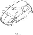
FIG. 4 is a perspective view for illustrating a state in which the bracket is mounted to a vehicle body. -
FIG. 5A is a side view for illustrating the first error. -
FIG. 5B is a side view for illustrating a second error. -
FIG. 5C is a side view for illustrating a third error. -
FIG. 6 is a perspective view for illustrating a position and a posture of a detector mounted to the vehicle body. -
FIG. 7 is a flow chart of an image processing program. -
FIG. 8 is a block diagram of an in-vehicle camera system according to a modification example of the present invention. -
FIG. 9 is a perspective view for illustrating an image pickup apparatus and a bracket in another modification example of the present invention. - An in-vehicle camera system (in-vehicle sensor system) 1 according to at least one embodiment of the present invention includes, as illustrated in
FIG. 1 , animage pickup apparatus 10 and anexternal apparatus 20. The in-vehicle camera system 1 is connected to a driving assistance apparatus DA via a network CAN. As described later, the in-vehicle camera system 1 corrects image data representing an image obtained by photographing a front view of a vehicle, and supplies the corrected image data to the driving assistance apparatus DA via the network CAN. The driving assistance apparatus DA executes various types of driving assistance based on the image data supplied from the in-vehicle camera system 1. - The image pickup apparatus (camera unit) 10 includes a casing (case main body) 11, a detector (image pickup unit) 12, an image processor (data processing device) 13, and a first storage (memory) 14.
- The
casing 11 is, as illustrated inFIG. 2A and FIG. 2B , a box member having a substantially cuboid shape. Thedetector 12, theimage processor 13, and thefirst storage 14 are held (accommodated or fixed) by thecasing 11. As described later, thecasing 11 may be shaped as illustrated inFIG. 9 . - The
detector 12 is a monocular camera. As illustrated inFIG. 3 , thedetector 12 includes alens 12a and animage sensor 12b. Thedetector 12 guides, to theimage sensor 12b through thelens 12a, light from a target object and a background within a predetermined range having an optical axis (center axis) C1 of thelens 12a as a center axis and converts the light into image data by theimage sensor 12b. That is, thedetector 12 photographs a target object and a landscape within a predetermined range, and supplies image data representing an image obtained by the photographing to theimage processor 13. This image data is not subjected to correction (position and posture correction) to be described later, and is thus sometimes referred to as "original image data" for the sake of convenience. - Referring back to
FIG. 1 , theimage processor 13 includes a microcomputer including a CPU, a ROM, a RAM, a communication interface, and the like. The CPU of theimage processor 13 subjects the original image data supplied from thedetector 12 to correction (position and posture correction) processing based on "a first error E1 and a second error E2" to be described later, to thereby generate corrected image data. The CPU transmits (supplies) the corrected image data to the driving assistance apparatus DA via the network CAN. The first error E1, the second error E2, and a third error E3 are sometimes referred to as "first data," "second data," and "third data," respectively. - The
first storage 14 is a device for storing the first error E1 to be described later, and includes a rewritable nonvolatile memory (for example, an EEPROM or a one-time programmable ROM). Thefirst storage 14 is connected to the CPU of theimage processor 13 via a bus BS. - The
external apparatus 20 is an electronic control unit (ECU), and includes asecond storage 21. Thesecond storage 21 includes a memory for storing the second error E2 to be described later. This memory is a rewritable nonvolatile memory (for example, an EEPROM). The external apparatus 20 (accordingly, the second storage 21) is connected to the CPU of theimage processor 13 and a microcomputer (not shown) of the driving assistance apparatus DA via the network CAN. - As illustrated in
FIG. 4 , theimage pickup apparatus 10 is fixed to an upper portion of a front windshield glass G of a vehicle body B of a vehicle. Specifically, a bracket BC illustrated inFIG. 2A and FIG. 2B is fixed through adhesion at a predetermined position (center position in a vehicle width direction) on a vehicle cabin inner side of the upper portion of the front windshield glass G (seeFIG. 4 ). As described later, the bracket BC may be shaped as illustrated inFIG. 9 . Thecasing 11 of theimage pickup apparatus 10 is fitted to this bracket BC. Accordingly, a mounting error of thecasing 11 with respect to the bracket BC does not occur in fact. When thecasing 11 is fitted to the bracket BC, "a position and a posture" of the image pickup apparatus 10 (accordingly, the detector 12) with respect to the vehicle body B are determined. The position of thedetector 12 with respect to the vehicle body B includes a position of thedetector 12 in the vehicle width direction, a position of thedetector 12 in a height direction, and a position of thedetector 12 in a longitudinal direction of the vehicle body B. The posture of thedetector 12 with respect to the vehicle body B includes "a pan angle, a tilt angle, and a roll angle" of thedetector 12 with respect to the vehicle body B. - The external apparatus 20 (accordingly, the second storage 21) is fixed with respect to the vehicle body B in a dashboard DB of the vehicle body B (see
FIG. 4 ). Theexternal apparatus 20 is connected to theimage pickup apparatus 10 and the driving assistance apparatus DA by a communication cable (not shown). - Incidentally, the
detector 12 is manufactured separately from thecasing 11. At a production factory (assembly factory) of theimage pickup apparatus 10, thedetector 12 is mounted (fixed) to thecasing 11. At this time, a mounting error of thedetector 12 to thecasing 11 is caused. That is, as illustrated inFIG. 3 andFIG. 5A , in some cases, "an actual position and an actual posture (see the solid lines ofFIG. 3 andFIG. 5A )" of thedetector 12 with respect to thecasing 11 differ from "a normal (design) position and a normal (design) posture (see the long-dashed double-short dashed lines ofFIG. 3 andFIG. 5A )" of thedetector 12 with respect to thecasing 11. - In view of the above, at the production factory of the
image pickup apparatus 10, the mounting error of thedetector 12 to thecasing 11 is measured through use of a well-known measurement method. This mounting error is a deviation amount of "the actual position and the actual posture" of thedetector 12 with respect to thecasing 11 from "the normal position and the normal posture" of thedetector 12 with respect to thecasing 11, and is hereinafter referred to as "first error E1." In the figures includingFIG. 3 in which the position and the posture of thedetector 12 are drawn, errors including the first error E1 are drawn in a relatively large scale (in an emphasized manner), but actual errors are minute. - The first error E1 includes, as listed below, an error of the position of the
detector 12 with respect to thecasing 11, and an error of the posture of thedetector 12 with respect to thecasing 11. - When it is assumed that the
casing 11 is mounted at a normal position and in a normal posture with respect to the vehicle body B, the following deviation amounts are caused from the normal position of thedetector 12 with respect to the casing 11: - ˙a deviation amount (E1dw) of the actual position in the vehicle width direction of the
detector 12 with respect to thecasing 11; - ˙a deviation amount (E1dh) of the actual position in the vehicle height direction of the
detector 12 with respect to thecasing 11; and - ˙a deviation amount (E1df) of the actual position in the vehicle longitudinal direction of the
detector 12 with respect to thecasing 11. - When it is assumed that the
casing 11 is mounted at a normal position and in a normal posture with respect to the vehicle body B, the following deviation amounts are caused from the normal posture of thedetector 12 with respect to the casing 11: - ˙a deviation amount (E1θp) of a pan angle of the
detector 12 with respect to thecasing 11; - ˙a deviation amount (E1θt) of a tilt angle of the
detector 12 with respect to thecasing 11; and - ˙a deviation amount (E1θr) of a roll angle of the
detector 12 with respect to thecasing 11. - That is, it can be said that the first error E1 is a vector including E1dw, E1dh, E1df, E1θp, E1θt, and E1θr as elements.
- Now, in order to simplify the description, it is assumed that, as illustrated in
FIG. 5A , among the elements of the first error E1, only "the deviation amount (E1θt) of the tilt angle, which is one error of the posture of thedetector 12 with respect to the casing 11 (casing longitudinal reference line K1)" has a value other than "0". That is, it is assumed that "other elements of the first error E1" other than E1θt are "0". At the production factory, the first error E1 (in this example, E1θt) is written into thefirst storage 14. The work of measuring the first error E1 and writing the first error E1 into thefirst storage 14 is performed by a worker operating a jig (for example, a target board or a computer apparatus). Theimage processor 13 may have a function of automatically executing part of the work. - In addition, when the bracket BC is mounted to the vehicle body B (in an actual case, to the front windshield glass G), a mounting error of the bracket BC to the vehicle body B is caused. Thus, as indicated by the solid lines of
FIG. 5B andFIG. 6 , when thecasing 11 is fixed to the bracket BC, even in a case in which there is no first error E1 described above, in some cases, "an actual position and an actual posture" of thedetector 12 with respect to the vehicle body B deviate from "a normal position and a normal posture" of thedetector 12 with respect to the vehicle body B. InFIG. 5B andFIG. 6 , thecasing 11 fixed to the vehicle body B at "the normal position and in the normal posture" is indicated by the long-dashed double-short-dashed lines. - A deviation amount of "the actual position and the actual posture" of the
detector 12 with respect to the vehicle body B from "the normal position and the normal posture" of thedetector 12 with respect to the vehicle body B in a case in which theimage pickup apparatus 10 having no first error E1 is fixed to the vehicle body B by the bracket BC is referred to as "second error E2." The second error E2 is an amount representing the mounting error of the bracket BC to the vehicle body B (front windshield glass G), and can be also said as an amount representing a mounting error of thecasing 11 with respect to the vehicle body B. The second error E2 includes, as listed below, an error of the position of thecasing 11 with respect to the vehicle body B, and an error of the posture of thecasing 11 with respect to the vehicle body B. - The following deviation amounts are caused from the normal position of the
casing 11 with respect to the vehicle body B: - ˙a deviation amount (E2dw) of the actual position in the vehicle width direction of the
casing 11; - ˙a deviation amount (E2dh) of the actual position in the vehicle height direction of the
casing 11; and - ˙a deviation amount (E2df) of the actual position in the vehicle longitudinal direction of the
casing 11. - The following deviation amounts are caused from the normal posture of the
casing 11 with respect to the vehicle body B: - ˙a deviation amount (E2θp) of an actual pan angle of the
casing 11; - ˙a deviation amount (E2θt) of an actual tilt angle of the
casing 11; and ˙a deviation amount (E2θr) of an actual roll angle of thecasing 11. - That is, it can be said that the second error E2 is a vector including E2dw, E2dh, E2df, E2θp, E2θt, and E2θr as elements.
- Now, in order to simplify the description, it is assumed that, as illustrated in
FIG. 5B , among the elements of the second error E2, only "the deviation amount (E2θt) of the tilt angle, which is one error of the posture of thecasing 11 with respect to the vehicle body B (vehicle body longitudinal reference line K2)" has a value other than "0". That is, it is assumed that "other elements of the second error E2" other than E2θt are "0". - Incidentally, in an actual case, the image pickup apparatus 10 (that is, the casing 11) having the first error E1 (E1θt) illustrated in
FIG. 5A is fixed to the bracket BC. As a result, as illustrated inFIG. 5C , a deviation amount of "the actual position and the actual posture" of thedetector 12 with respect to the vehicle body B from "the normal position and the normal posture" of thedetector 12 with respect to the vehicle body B is an amount including the first error E1 and the second error E2 (hereinafter referred to as "third error E3" for the sake of convenience). That is, for example, the deviation amount (E3θt) of the tilt angle of the third error E3 is obtained as a sum of the deviation amount (E1θt) of the tilt angle of the first error E1 and the deviation amount (E2θt) of the tilt angle of the second error E2. In other words, when the third error E3 is measured, the first error E1 is already written in thefirst storage 14, and hence the second error E2 (that is, the amount representing the mounting error of the bracket BC to the vehicle body B) can be obtained from the third error E3 and the first error E1. - The third error E3 includes, as listed below, an error of the position of the
detector 12 with respect to the vehicle body B, and an error of the posture of thedetector 12 with respect to the vehicle body B. - The following deviation amounts are caused from the normal position of the
detector 12 with respect to the vehicle body B: - ˙a deviation amount (E3dw) of the actual position in the vehicle width direction of the
detector 12; - ˙a deviation amount (E3dh) of the actual position in the vehicle height direction of the
detector 12; and - ˙a deviation amount (E3df) of the actual position in the vehicle longitudinal direction of the
detector 12. - The following deviation amounts are caused from the normal posture of the
detector 12 with respect to the vehicle body B: - ˙a deviation amount (E3θp) of the actual pan angle of the
detector 12; - ˙a deviation amount (E3θt) of the actual tilt angle of the
detector 12; and - ˙a deviation amount (E3θr) of the actual roll angle of the
detector 12. - That is, it can be said that the third error E3 is a vector including E3dw, E3dh, E3df, E3θp, E3θt, and E3θr as elements.
- The third error E3 (E3θt of
FIG. 5C ) is measured by a well-known method at the vehicle production factory including a step of mounting thecasing 11 to the bracket BC fixed to the vehicle body B. For example, a target board is arranged with high precision at a predetermined specific position ahead of the vehicle, and this target board is photographed by "theimage pickup apparatus 10 fixed to the vehicle" so that the original image data is acquired. Next, this original image data is compared with standard image data so that the third error E3 is calculated. The standard image data is image data obtained when theimage pickup apparatus 10 in a state in which "the position and the posture" with respect to the vehicle body B are normal photographs the target board arranged at the above-mentioned specific position, and is prepared in advance. Those steps of processing are executed through use of a dedicated measurement apparatus (computer) connected to theimage pickup apparatus 10 fixed to the vehicle. - Next, the measurement apparatus reads the first error E1 from the
first storage 14 of theimage pickup apparatus 10 fixed to the vehicle, and obtains the second error E2 through calculation based on this first error E1 and on the third error E3 obtained through measurement and calculation. For example, as can be inferred from the fact that E2θt can be obtained by subtracting E1θt from E3θt, basically, when the first error E1 being a vector is subtracted from the third error E3 being a vector, the second error E2 being a vector can be obtained. Then, the measurement apparatus writes the obtained second error E2 into thesecond storage 21 of theexternal apparatus 20. - After the vehicle is shipped, the CPU of the
image processor 13 reads out the first error E1 and the second error E2 from thefirst storage 14 and thesecond storage 21, respectively. Then, the CPU obtains the third error E3 based on the first error E1 and the second error E2, and corrects the original image data based on the third error E3, to thereby generate the corrected image data (normal image data). That is, the corrected image data is image data expected to be output from thedetector 12 under a state in which the third error E3 is "0" (that is, a state in which the position and the posture of thedetector 12 on the vehicle body match the normal position and the normal posture). The CPU of theimage processor 13 transmits the corrected image data to the microcomputer (not shown) of the driving assistance apparatus DA, and the microcomputer of the driving assistance apparatus DA executes the driving assistance control of each output through use of the corrected image data. - Next, with reference to
FIG. 7 , an operation of the CPU of theimage processor 13 is specifically described. - When an ignition key switch (not shown) is changed from an OFF position to an ON position under a state in which the in-vehicle camera system 1 is installed on the vehicle, the in-vehicle camera system 1 is activated, and the CPU starts execution of the image processing program from
Step 700 ofFIG. 7 . - Next, in
Step 701, the CPU determines whether or not the second error E2 is stored in thesecond storage 21. That is, the CPU determines whether a current time point is not a time point immediately after theimage pickup apparatus 10 is fixed to the bracket BC and required electrical connection is established at the vehicle production factory. - When the second error E2 is stored in the second storage 21 (Step 701: Yes), the process proceeds to Step 702, and the CPU reads out the first error E1 and the second error E2 from the
first storage 14 and thesecond storage 21, respectively. - Next, in
Step 703, the CPU obtains the third error E3 based on the first error E1 and the second error E2, and determines, based on this third error E3, an image conversion parameter (image conversion matrix component) for converting (correcting) the original image data into the corrected image data. - Next, in
Step 704, the CPU acquires the original image data from thedetector 12. - Next, in Step 705, the CPU corrects the acquired original image data through use of the image conversion parameter to generate the corrected image data (normal image data), and supplies the corrected image data to the driving assistance ECU.
- Then, the CPU repeatedly performs the processing steps of
Step 704 and Step 705. Accordingly, the CPU generates the corrected image data every time the original image data is acquired from thedetector 12, and supplies the corrected image data to the driving assistance ECU. - On the other hand, when the current time point is a time point immediately after the
image pickup apparatus 10 is fixed to the bracket BC and the required electrical connection is established at the vehicle production factory, no second error E2 is stored in thesecond storage 21. In this case, the CPU determines "No" inStep 701, and sequentially performs processing steps of fromStep 706 to Step 714 described below. Then, the process proceeds to Step 702. - Step 706: The CPU causes a display apparatus installed on a predetermined vehicle to display an image for requesting a worker to prepare for obtaining the third error (finally, the second error E2 is obtained through calculation in
Step 714 to be described later). - This display apparatus installed on the vehicle is, for example, a liquid crystal display apparatus of a navigation system of the vehicle.
- When the worker recognizes that the image is displayed, the worker arranges a target board at a predetermined specific position ahead of the vehicle. A positional relationship between the vehicle and the target board greatly affects a measurement result of the third error E3 (finally, the value of the second error E2). Thus, the work of arranging the target board is required to be performed accurately.
- Next, the worker connects a specific computer apparatus (jig) to the network CAN so that a measurement start command representing that the measurement of the third error E3 is to be started is transmitted from the specific computer apparatus to the CPU of the
image processor 13. - Step 707: The CPU monitors whether or not the measurement start command has been received. The CPU stands by until the measurement start command is received, and the process proceeds to Step 708 after the measurement start command is received.
- Step 708: The CPU starts the processing for obtaining the third error E3, and causes the display apparatus to display an image representing that the measurement is in process.
- Step 709: The CPU causes the
detector 12 to photograph current image data representing the target board, and acquires the original image data obtained through the photographing. - Step 710: The CPU analyzes the image of the target board represented by the original image data acquired in
Step 709 through comparison with the standard image data. That is, the CPU obtains the third error E3 through calculation based on "a position, a posture, a distortion (degree of curvature)," and the like of "a mark drawn on the target board" in the original image data. - Step 711: The CPU reads out the first error E1 from the
first storage 14. - Step 712: The CPU obtains the second error E2 through calculation based on the third error E3 obtained in
Step 710 and the first error E1 read out inStep 711. For example, the CPU subtracts the first error E1 being a vector from the third error E3 being a vector to obtain the second error E2 (=E3-E1). - Step 713: The CPU transmits the obtained second error E2 to the
external apparatus 20 via the network CAN, and stores the second error E2 into thesecond storage 21. - Step 714: The CPU causes the display apparatus to display an image representing that the acquisition of the second error E2 and the storage of the second error E2 into the
second storage 21 are ended. At this time point, the worker disconnects the specific computer apparatus from the network CAN. Then, the process proceeds to Step 702. - The processing steps of from
Step 710 to Step 713 may be executed while the specific computer apparatus performs data exchange with theimage processor 13. - As described above, at a time point immediately after the in-vehicle camera system 1 is mounted to the vehicle body in the vehicle production step, the second error E2 has not been stored in the
second storage 21 yet. Accordingly, the process proceeds fromStep 701 to Step 706, and the CPU executes a series of processing steps of fromStep 706 to Step 714 to store the second error E2 into thesecond storage 21. - After the vehicle is shipped from the production factory, when the
image pickup apparatus 10 is normal, the CPU executes the processing steps of fromStep 701 to Step 703 at the time of activation, and then repeats the processing steps ofStep 704 and Step 705. - Meanwhile, after the vehicle is shipped from the production factory, in some cases, the
image pickup apparatus 10 fails, and theimage pickup apparatus 10 is replaced. In those cases, the worker removes the failedimage pickup apparatus 10 from the bracket BC, and fits a newimage pickup apparatus 10 to the bracket BC so as to fix the newimage pickup apparatus 10 to the vehicle. That is, in this case, the bracket BC is not replaced, and is still fixed to the front windshield glass G. Theexternal apparatus 20 is also not replaced, and is still fixed inside the dashboard DB. As described above, when theimage pickup apparatus 10 fails, a newimage pickup apparatus 10 is mounted to the bracket BC fixed to the front windshield glass G at the production factory. Thus, "the position and the posture (that is, the second error E2)" of thecasing 11 with respect to the vehicle body B do not change before and after the replacement of theimage pickup apparatus 10. This second error E2 is measured at the time of production of the vehicle, and is stored in thesecond storage 21 of theexternal apparatus 20. Thus, when theimage pickup apparatus 10 is replaced, it is not required to obtain the second error E2 again. That is, when the in-vehicle camera system 1 is activated after theimage pickup apparatus 10 is replaced, the process directly proceeds fromStep 701 to Step 702 instead of proceeding fromStep 701 to Step 702 viaStep 706 to Step 714. - In
Step 702, the CPU reads out, from thefirst storage 14, the first error E1 specific to the currentimage pickup apparatus 10 mounted to the bracket BC, and reads out, from thesecond storage 21, the second error E2 independent of the individualimage pickup apparatus 10. Then, inStep 703, the CPU determines the image conversion parameter based on the first error E1 and the second error E2 (that is, the third error E3), and, in Step 705, the CPU corrects the original image data through use of the image conversion parameter. - As is understood from the above, the first error E1 specific to the
image pickup apparatus 10 mounted to the vehicle body B at the current time point is reflected in the image conversion parameter. Thus, according to the at least one embodiment, when theimage pickup apparatus 10 is replaced, without troublesome work of measuring the position and the posture of thedetector 12 of theimage pickup apparatus 10 after the replacement, the corrected image data having the same level of precision before and after the replacement of theimage pickup apparatus 10 can be transmitted from theimage pickup apparatus 10 to the driving assistance apparatus DA. - In the above, the in-vehicle camera system 1 according to the at least one embodiment has been described, but the present invention is not limited to the above-mentioned at least one embodiment, and various changes are possible within the range not departing from the object of the present invention as defined in the appended claims.
- In the above-mentioned at least one embodiment, the second error E2 is obtained based on the first error E1 and the third error E3, and this second error E2 is stored in the
second storage 21. As another example, the first error E1 and the third error E3 may be stored in thesecond storage 21. In this case, when theimage pickup apparatus 10 is replaced, theimage pickup apparatus 10 after the replacement reads out, from thesecond storage 21, "the first error E1 and the third error E3 of theimage pickup apparatus 10 before the replacement," and obtains the second error E2 from "the third error E3 and the first error E1." Then, theimage pickup apparatus 10 after the replacement obtains the image conversion parameter from the obtained second error E2 and the first error E1 stored in thefirst storage 14 of theimage pickup apparatus 10 after the replacement. This image conversion parameter may be used to correct the original image data of theimage pickup apparatus 10 after the replacement to obtain the corrected image data. - In the above-mentioned at least one embodiment, the first error E1 is stored in the
first storage 14, but in place of the first error E1, a first adjustment value being a value corresponding to the first error E1 and for use to correct the mounting error of thedetector 12 to thecasing 11 may be stored in thefirst storage 14. For example, it is preferred that the first adjustment value be determined by a jig (measurement apparatus) for measuring the first error E1 at the time of production of theimage pickup apparatus 10, theimage processor 13, or the like. In this case, it is preferred that, in place of the second error E2, a second adjustment value being a value corresponding to the second error E2 and for use to correct the mounting error of the bracket BC to the vehicle body be stored in thesecond storage 21. For example, it is preferred that the second adjustment value be determined by a jig (measurement apparatus) for measuring the second error E2 at the time of production of the vehicle, theimage processor 13, or the like. In this case, the CPU of theimage processor 13 may correct the original image data based on the first adjustment value and the second adjustment value. - In the above-mentioned at least one embodiment, the
image processor 13 is provided inside of thecasing 11, but as another example, as illustrated inFIG. 8 , theimage processor 13 may be provided outside of thecasing 11. That is, in this example, theimage processor 13 is connected to thedetector 12 and thefirst storage 14 and to thesecond storage 21 via the network CAN. Theimage processor 13 acquires the original image data, the first error E1, and the second error E2 from thedetector 12, thefirst storage 14, and thesecond storage 21, respectively. Then, theimage processor 13 corrects the original image data based on the first error E1 and the second error E2, and supplies the corrected image data to the driving assistance apparatus DA. In this case, theimage processor 13 may be incorporated in another apparatus, for example, theexternal apparatus 20 or the driving assistance apparatus DA. - In the above-mentioned at least one embodiment, the second error E2 is stored in the
external apparatus 20, but the second error E2 may be stored in a storage device of "the driving assistance apparatus DA, an engine control apparatus, or a brake control apparatus" serving as theexternal apparatus 20. That is, a part of a storage area of a storage device of another in-vehicle component may be used as theexternal apparatus 20. In this case, it is preferred that the another in-vehicle component be a component that has a low possibility of replacement. - The present invention is also applicable to another surrounding monitoring sensor system other than the in-vehicle camera system 1. For example, the present invention is also applicable to a radar sensor system. The radar sensor system includes a radar apparatus and an external apparatus. The radar apparatus includes a detector, a controller, a first storage, and a casing. The detector includes a transmitter for transmitting radar waves, and a receiver for receiving reflected waves. A deviation amount (first error E1) of "an actual position and an actual posture" of the detector with respect to the casing from "a normal position and a normal posture" of the detector with respect to the casing is stored in the first storage included in the radar apparatus. The casing is fixed to a bracket fixed with respect to the vehicle body. At the vehicle production factory, when the casing is fixed to the vehicle body through intermediation of the bracket, a deviation amount (third error E3) of "an actual position and an actual posture" of the detector of the radar apparatus with respect to the vehicle body from "a normal position and a normal posture" of the detector of the radar apparatus with respect to the vehicle body is measured. Further, a deviation amount (second error E2) of "an actual position and an actual posture" of the casing with respect to the vehicle body from "a normal position and a normal posture" of the casing with respect to the vehicle body is obtained from the third error E3 and the first error E1 stored in the first storage included in the radar apparatus, and the deviation amount (second error E2) is stored in the second storage of the external apparatus. The controller reads out the first error E1 and the second error E2 from the first storage and the second storage, respectively, corrects data output from the detector ("distance and direction from the vehicle" of the target object around the vehicle) based on the first error E1 and the second error E2, and transmits the corrected data to the driving assistance apparatus.
- The
casing 11 of theimage pickup apparatus 10 and the bracket BC may be shaped as illustrated inFIG. 9 . In this case, the bracket BC includes adhesion portions Ad at a plurality of upper portions. The adhesion portions Ad are caused to adhere to the front windshield glass G with an adhesive so that the bracket BC is fixed to the front windshield glass G. Further, thecasing 11 is mounted to the bracket BC from below, and is fixed to the bracket BC by a fixing unit (not shown). - The first error E1 includes "the error of the position of the
detector 12 with respect to thecasing 11 and the error of the posture of thedetector 12 with respect to thecasing 11" in a case in which it is assumed that thecasing 11 is mounted at a normal position and in a normal posture with respect to the vehicle body B. However, the first error E1 is not only required to be a value obtained in a case in which it is assumed that thecasing 11 is mounted at a normal position and in a normal posture with respect to the vehicle body B. In this case, inStep 712, the CPU may convert the first error E1 into "an error in a case in which it is assumed that thecasing 11 is mounted at a normal position and in a normal posture with respect to the vehicle body B," and then may obtain the second error E2.
Claims (5)
- An in-vehicle sensor system (1), comprising:a surrounding sensor (10) including:a casing (11);a detector (12) which is supported by the casing (11), and is configured to output detection data representing a situation within a detection range determined through use of, as a reference, an axis extending from a predetermined point of the detector;the in-vehicle sensor system (1) being characterized in that:the casing (11) is configured to be removably mounted to a bracket (BC) fixed to a vehicle body (B) of the vehicle;the surrounding sensor (10) comprises a first storage (14) configured to store therein first data (E1) corresponding to a deviation amount of an actual position and an actual posture of the detector (12) with respect to the casing (11) from a predetermined normal design position and a predetermined normal design posture of the detector (12) with respect to the casing (11);the in-vehicle sensor system (1) comprises a second storage (21) which is provided separately from the surrounding sensor (10) and is configured to be fixed to the vehicle body, and is configured to store second data (E2; E1, E3) corresponding to a deviation amount of an actual position and an actual posture of the casing (11) with respect to the vehicle body (B) from a predetermined normal design position and a predetermined normal design posture of the casing (11) with respect to the vehicle body (B); andthe in-vehicle sensor system (1) comprises a corrector (13) which is provided on one of an inner side and an outer side of the casing (11), and is configured to read out, when the second data is stored in the second storage (21), the first data and the second data from the first storage (14) and the second storage (21), respectively, and to correct the detection data output from the detector (12) based on the read-out first data and the read-out second data, to thereby generate and output data expected to be output by the detector (12) when it is assumed that the detector (12) is fixed at a predetermined normal design position and in a predetermined normal design posture with respect to the vehicle body (B).
- The in-vehicle sensor system according to claim 1, wherein the second storage (21) is configured to store, as the second data, data (E2) directly representing the deviation amount of the actual position and the actual posture of the casing (11) with respect to the vehicle body (B) from the predetermined normal design position and the predetermined normal design posture of the casing (11) with respect to the vehicle body (B).
- The in-vehicle sensor system according to claim 1, wherein the second storage (21) is configured to store, as the second data, data of a combination of:third data (E3) directly representing a deviation amount of an actual position and an actual posture of the detector (12) with respect to the vehicle body (B) from a predetermined normal design position and a predetermined normal design posture of the detector (12) with respect to the vehicle body (B); andfirst data (E1) directly representing the deviation amount of the actual position and the actual posture of the detector (12) with respect to the casing (11) from the predetermined normal design position and the predetermined normal design posture of the detector (12) with respect to the casing (11), in a case in which the third data (E3) is obtained.
- The in-vehicle sensor system according to any one of claims 1 to 3, wherein the second storage (21) is an area of a part of a storage area of a storage device included in an in-vehicle component which is provided separately from the surrounding sensor (10).
- A data generation method for an in-vehicle sensor system, to be applied to the in-vehicle sensor system (1),
the in-vehicle sensor system (1) including:a surrounding sensor (10) including:a casing (11) configured to be removably mounted to a bracket (BC) fixed to a vehicle body (B) of a vehicle;a detector (12) which is supported by the casing (11), and is configured to output detection data representing a situation within a detection range determined through use of, as a reference, an axis extending from a predetermined point of the detector; anda first storage (14) configured to store therein first data (E1) corresponding to a deviation amount of an actual position and an actual posture of the detector (12) with respect to the casing (11) from a predetermined normal design position and a predetermined normal design posture of the detector (12) with respect to the casing (11); anda second storage (21) which is provided separately from the surrounding sensor (10) and is configured to be fixed to the vehicle body (B), and is configured to store second data (E2; E1, E3) corresponding to a deviation amount of an actual position and an actual posture of the casing (11) with respect to the vehicle body (B) from a predetermined normal design position and a predetermined normal design posture of the casing (11) with respect to the vehicle body (B),the data generation method comprising:- a data correcting step of reading out (702), by a corrector (13) which is provided on one of an inner side and an outer side of the casing (11), the first data and the second data from the first storage (14) and the second storage (21), respectively, when the second data is stored in the second storage,- correcting (705), by the corrector (13), the detection data output from the detector (12) based on the read-out first data and the read-out second data, to thereby generate and output data expected to be output by the detector when it is assumed that the detector (12) is fixed at a predetermined normal design position and in a predetermined normal design posture with respect to the vehicle body (B);- a first data storing step of acquiring the first data through measurement at a stage at which the detector (12) is fixed to the casing (11) and before the casing (11) is fixed to the bracket (BC), and storing the acquired first data into the first storage (14);- a second data storing step of acquiring from the detector (12), detection data representing a target arranged at a predetermined position with respect to the vehicle at a stage at which the casing (11) is fixed to the bracket (BC) and before the vehicle is shipped from a production factory of the vehicle, acquiring the second data based on the acquired detection data and the first data, and storing the acquired second data into the second storage (21).
Applications Claiming Priority (1)
| Application Number | Priority Date | Filing Date | Title |
|---|---|---|---|
| JP2021023921A JP7533271B2 (en) | 2021-02-18 | 2021-02-18 | On-board sensor system and data generation method for on-board sensor system |
Publications (2)
| Publication Number | Publication Date |
|---|---|
| EP4047919A1 EP4047919A1 (en) | 2022-08-24 |
| EP4047919B1 true EP4047919B1 (en) | 2024-07-10 |
Family
ID=80225798
Family Applications (1)
| Application Number | Title | Priority Date | Filing Date |
|---|---|---|---|
| EP22154646.8A Active EP4047919B1 (en) | 2021-02-18 | 2022-02-01 | In-vehicle sensor system, and data generation method for in-vehicle sensor system |
Country Status (4)
| Country | Link |
|---|---|
| US (1) | US12094217B2 (en) |
| EP (1) | EP4047919B1 (en) |
| JP (1) | JP7533271B2 (en) |
| CN (1) | CN114979424B (en) |
Family Cites Families (16)
| Publication number | Priority date | Publication date | Assignee | Title |
|---|---|---|---|---|
| CA2529498A1 (en) * | 2003-07-24 | 2005-02-03 | Cognitens Ltd. | Method and sytem for the three-dimensional surface reconstruction of an object |
| JP2005114683A (en) * | 2003-10-10 | 2005-04-28 | Nippon Soken Inc | Lens displacement detection method and lens displacement detection device |
| JP2006074329A (en) | 2004-09-01 | 2006-03-16 | Nissan Motor Co Ltd | Optical axis adjustment device for in-vehicle camera |
| JP4780534B2 (en) * | 2009-01-23 | 2011-09-28 | トヨタ自動車株式会社 | Road marking line detection device |
| DE102011078631A1 (en) * | 2011-07-05 | 2013-01-10 | Robert Bosch Gmbh | Arrangement and method for determining an imaging deviation of a camera |
| JP6012982B2 (en) | 2012-02-24 | 2016-10-25 | 京セラ株式会社 | Calibration processing apparatus, camera calibration apparatus, camera system, and camera calibration method |
| EP2645701A1 (en) * | 2012-03-29 | 2013-10-02 | Axis AB | Method for calibrating a camera |
| JP6439287B2 (en) * | 2014-06-18 | 2018-12-19 | 株式会社デンソー | Driving support device, driving support method, image correction device, and image correction method |
| CN105376564B (en) * | 2015-11-24 | 2018-01-02 | 深圳创维-Rgb电子有限公司 | Camera calibration equipment and its control method and device |
| US10565736B2 (en) * | 2016-01-15 | 2020-02-18 | Sony Corporation | Image processing apparatus and method, program, and image processing system |
| CN210062890U (en) * | 2018-04-20 | 2020-02-14 | 株式会社小糸制作所 | Sensor module |
| JP2020008389A (en) * | 2018-07-06 | 2020-01-16 | 豊田合成株式会社 | Vehicle sensor unit |
| US11454525B2 (en) * | 2018-10-19 | 2022-09-27 | Robert Bosch Gmbh | Vehicle sensor field calibration utilizing other vehicles |
| TWI689432B (en) * | 2018-12-26 | 2020-04-01 | 財團法人工業技術研究院 | Automatic vehicular sensor adjustment method and system thereof |
| JP7099354B2 (en) | 2019-02-15 | 2022-07-12 | トヨタ自動車株式会社 | Driving support device |
| JP7128449B2 (en) * | 2019-04-18 | 2022-08-31 | トヨタ自動車株式会社 | Driving assistance device and adjustment method for the driving assistance device |
-
2021
- 2021-02-18 JP JP2021023921A patent/JP7533271B2/en active Active
- 2021-12-30 US US17/565,520 patent/US12094217B2/en active Active
-
2022
- 2022-02-01 EP EP22154646.8A patent/EP4047919B1/en active Active
- 2022-02-16 CN CN202210141514.3A patent/CN114979424B/en active Active
Also Published As
| Publication number | Publication date |
|---|---|
| US20220262125A1 (en) | 2022-08-18 |
| US12094217B2 (en) | 2024-09-17 |
| JP7533271B2 (en) | 2024-08-14 |
| JP2022126066A (en) | 2022-08-30 |
| CN114979424B (en) | 2024-01-23 |
| CN114979424A (en) | 2022-08-30 |
| EP4047919A1 (en) | 2022-08-24 |
Similar Documents
| Publication | Publication Date | Title |
|---|---|---|
| JP6458439B2 (en) | On-vehicle camera calibration device, image generation device, on-vehicle camera calibration method, and image generation method | |
| KR101787304B1 (en) | Calibration method, calibration device, and computer program product | |
| US10775621B2 (en) | Method, device and computer-readable storage medium with instructions for setting a head-up display in a transportation vehicle | |
| JP4737317B2 (en) | Vehicle periphery shooting display system | |
| JP6520080B2 (en) | Stereo camera calibration method, parallax calculation device, stereo camera and vehicle | |
| US11097670B2 (en) | Method for calibrating image data of an imaging system for a vehicle combination | |
| US20080159594A1 (en) | Bird view visual system with fisheye distortion calibration and method thereof | |
| US20220091267A1 (en) | Method for ascertaining an operating parameter for operating a surroundings detection system for a vehicle, and surroundings detection system | |
| KR102227850B1 (en) | Method for adjusting output video of rear camera for vehicles | |
| CN111572471B (en) | Vehicle driving support device | |
| JP2009204459A (en) | Inertial force sensor for vehicles and detecting method of inclination of vehicle | |
| EP4047919B1 (en) | In-vehicle sensor system, and data generation method for in-vehicle sensor system | |
| US12159381B2 (en) | Error-robust capture of vehicle surroundings | |
| JP7201568B2 (en) | vehicle controller | |
| CN114325621A (en) | ACC radar system remote calibration method and device and computer equipment | |
| US12498458B2 (en) | Calibration method and calibration system for a vehicle sensor | |
| WO2022004248A1 (en) | Information processing device, information processing method, and program | |
| JP2020165968A (en) | Calibration method, calibration equipment and program | |
| JP2021069070A (en) | Vehicle control device | |
| JP2019053073A (en) | Calibration method, calibration apparatus and program | |
| WO2019016942A1 (en) | Driving assistance device, server, and driving assistance method | |
| US12469172B2 (en) | Method for calibrating a sensor for a driver assistance system and control unit | |
| CN114347917B (en) | Calibration method and device for vehicle and vehicle-mounted camera system | |
| JP7704117B2 (en) | Vehicle-mounted camera calibration system, vehicle-mounted camera calibration method, and vehicle-mounted camera calibration program | |
| US20250128724A1 (en) | Self-diagnosis device for vehicle |
Legal Events
| Date | Code | Title | Description |
|---|---|---|---|
| PUAI | Public reference made under article 153(3) epc to a published international application that has entered the european phase |
Free format text: ORIGINAL CODE: 0009012 |
|
| STAA | Information on the status of an ep patent application or granted ep patent |
Free format text: STATUS: REQUEST FOR EXAMINATION WAS MADE |
|
| 17P | Request for examination filed |
Effective date: 20220201 |
|
| AK | Designated contracting states |
Kind code of ref document: A1 Designated state(s): AL AT BE BG CH CY CZ DE DK EE ES FI FR GB GR HR HU IE IS IT LI LT LU LV MC MK MT NL NO PL PT RO RS SE SI SK SM TR |
|
| STAA | Information on the status of an ep patent application or granted ep patent |
Free format text: STATUS: EXAMINATION IS IN PROGRESS |
|
| 17Q | First examination report despatched |
Effective date: 20230801 |
|
| REG | Reference to a national code |
Ref country code: DE Ref legal event code: R079 Free format text: PREVIOUS MAIN CLASS: H04N0005225000 Ipc: H04N0023500000 Ref document number: 602022004382 Country of ref document: DE |
|
| GRAP | Despatch of communication of intention to grant a patent |
Free format text: ORIGINAL CODE: EPIDOSNIGR1 |
|
| STAA | Information on the status of an ep patent application or granted ep patent |
Free format text: STATUS: GRANT OF PATENT IS INTENDED |
|
| RIC1 | Information provided on ipc code assigned before grant |
Ipc: H04N 17/00 20060101ALI20240213BHEP Ipc: B60R 11/04 20060101ALI20240213BHEP Ipc: B60R 1/00 20220101ALI20240213BHEP Ipc: H04N 23/57 20230101ALI20240213BHEP Ipc: H04N 23/50 20230101AFI20240213BHEP |
|
| INTG | Intention to grant announced |
Effective date: 20240313 |
|
| GRAS | Grant fee paid |
Free format text: ORIGINAL CODE: EPIDOSNIGR3 |
|
| GRAA | (expected) grant |
Free format text: ORIGINAL CODE: 0009210 |
|
| STAA | Information on the status of an ep patent application or granted ep patent |
Free format text: STATUS: THE PATENT HAS BEEN GRANTED |
|
| AK | Designated contracting states |
Kind code of ref document: B1 Designated state(s): AL AT BE BG CH CY CZ DE DK EE ES FI FR GB GR HR HU IE IS IT LI LT LU LV MC MK MT NL NO PL PT RO RS SE SI SK SM TR |
|
| REG | Reference to a national code |
Ref country code: CH Ref legal event code: EP |
|
| REG | Reference to a national code |
Ref country code: DE Ref legal event code: R096 Ref document number: 602022004382 Country of ref document: DE |
|
| REG | Reference to a national code |
Ref country code: LT Ref legal event code: MG9D |
|
| REG | Reference to a national code |
Ref country code: NL Ref legal event code: MP Effective date: 20240710 |
|
| P01 | Opt-out of the competence of the unified patent court (upc) registered |
Free format text: CASE NUMBER: APP_57246/2024 Effective date: 20241019 |
|
| PG25 | Lapsed in a contracting state [announced via postgrant information from national office to epo] |
Ref country code: PT Free format text: LAPSE BECAUSE OF FAILURE TO SUBMIT A TRANSLATION OF THE DESCRIPTION OR TO PAY THE FEE WITHIN THE PRESCRIBED TIME-LIMIT Effective date: 20241111 |
|
| REG | Reference to a national code |
Ref country code: AT Ref legal event code: MK05 Ref document number: 1703076 Country of ref document: AT Kind code of ref document: T Effective date: 20240710 |
|
| PG25 | Lapsed in a contracting state [announced via postgrant information from national office to epo] |
Ref country code: NL Free format text: LAPSE BECAUSE OF FAILURE TO SUBMIT A TRANSLATION OF THE DESCRIPTION OR TO PAY THE FEE WITHIN THE PRESCRIBED TIME-LIMIT Effective date: 20240710 |
|
| PG25 | Lapsed in a contracting state [announced via postgrant information from national office to epo] |
Ref country code: PT Free format text: LAPSE BECAUSE OF FAILURE TO SUBMIT A TRANSLATION OF THE DESCRIPTION OR TO PAY THE FEE WITHIN THE PRESCRIBED TIME-LIMIT Effective date: 20241111 Ref country code: NL Free format text: LAPSE BECAUSE OF FAILURE TO SUBMIT A TRANSLATION OF THE DESCRIPTION OR TO PAY THE FEE WITHIN THE PRESCRIBED TIME-LIMIT Effective date: 20240710 |
|
| REG | Reference to a national code |
Ref country code: DE Ref legal event code: R084 Ref document number: 602022004382 Country of ref document: DE |
|
| PG25 | Lapsed in a contracting state [announced via postgrant information from national office to epo] |
Ref country code: NO Free format text: LAPSE BECAUSE OF FAILURE TO SUBMIT A TRANSLATION OF THE DESCRIPTION OR TO PAY THE FEE WITHIN THE PRESCRIBED TIME-LIMIT Effective date: 20241010 |
|
| PG25 | Lapsed in a contracting state [announced via postgrant information from national office to epo] |
Ref country code: GR Free format text: LAPSE BECAUSE OF FAILURE TO SUBMIT A TRANSLATION OF THE DESCRIPTION OR TO PAY THE FEE WITHIN THE PRESCRIBED TIME-LIMIT Effective date: 20241011 Ref country code: PL Free format text: LAPSE BECAUSE OF FAILURE TO SUBMIT A TRANSLATION OF THE DESCRIPTION OR TO PAY THE FEE WITHIN THE PRESCRIBED TIME-LIMIT Effective date: 20240710 Ref country code: FI Free format text: LAPSE BECAUSE OF FAILURE TO SUBMIT A TRANSLATION OF THE DESCRIPTION OR TO PAY THE FEE WITHIN THE PRESCRIBED TIME-LIMIT Effective date: 20240710 |
|
| PG25 | Lapsed in a contracting state [announced via postgrant information from national office to epo] |
Ref country code: BG Free format text: LAPSE BECAUSE OF FAILURE TO SUBMIT A TRANSLATION OF THE DESCRIPTION OR TO PAY THE FEE WITHIN THE PRESCRIBED TIME-LIMIT Effective date: 20240710 |
|
| PG25 | Lapsed in a contracting state [announced via postgrant information from national office to epo] |
Ref country code: LV Free format text: LAPSE BECAUSE OF FAILURE TO SUBMIT A TRANSLATION OF THE DESCRIPTION OR TO PAY THE FEE WITHIN THE PRESCRIBED TIME-LIMIT Effective date: 20240710 |
|
| PG25 | Lapsed in a contracting state [announced via postgrant information from national office to epo] |
Ref country code: IS Free format text: LAPSE BECAUSE OF FAILURE TO SUBMIT A TRANSLATION OF THE DESCRIPTION OR TO PAY THE FEE WITHIN THE PRESCRIBED TIME-LIMIT Effective date: 20241110 Ref country code: AT Free format text: LAPSE BECAUSE OF FAILURE TO SUBMIT A TRANSLATION OF THE DESCRIPTION OR TO PAY THE FEE WITHIN THE PRESCRIBED TIME-LIMIT Effective date: 20240710 |
|
| PG25 | Lapsed in a contracting state [announced via postgrant information from national office to epo] |
Ref country code: HR Free format text: LAPSE BECAUSE OF FAILURE TO SUBMIT A TRANSLATION OF THE DESCRIPTION OR TO PAY THE FEE WITHIN THE PRESCRIBED TIME-LIMIT Effective date: 20240710 |
|
| PG25 | Lapsed in a contracting state [announced via postgrant information from national office to epo] |
Ref country code: ES Free format text: LAPSE BECAUSE OF FAILURE TO SUBMIT A TRANSLATION OF THE DESCRIPTION OR TO PAY THE FEE WITHIN THE PRESCRIBED TIME-LIMIT Effective date: 20240710 Ref country code: RS Free format text: LAPSE BECAUSE OF FAILURE TO SUBMIT A TRANSLATION OF THE DESCRIPTION OR TO PAY THE FEE WITHIN THE PRESCRIBED TIME-LIMIT Effective date: 20241010 |
|
| PG25 | Lapsed in a contracting state [announced via postgrant information from national office to epo] |
Ref country code: RS Free format text: LAPSE BECAUSE OF FAILURE TO SUBMIT A TRANSLATION OF THE DESCRIPTION OR TO PAY THE FEE WITHIN THE PRESCRIBED TIME-LIMIT Effective date: 20241010 Ref country code: PL Free format text: LAPSE BECAUSE OF FAILURE TO SUBMIT A TRANSLATION OF THE DESCRIPTION OR TO PAY THE FEE WITHIN THE PRESCRIBED TIME-LIMIT Effective date: 20240710 Ref country code: NO Free format text: LAPSE BECAUSE OF FAILURE TO SUBMIT A TRANSLATION OF THE DESCRIPTION OR TO PAY THE FEE WITHIN THE PRESCRIBED TIME-LIMIT Effective date: 20241010 Ref country code: LV Free format text: LAPSE BECAUSE OF FAILURE TO SUBMIT A TRANSLATION OF THE DESCRIPTION OR TO PAY THE FEE WITHIN THE PRESCRIBED TIME-LIMIT Effective date: 20240710 Ref country code: IS Free format text: LAPSE BECAUSE OF FAILURE TO SUBMIT A TRANSLATION OF THE DESCRIPTION OR TO PAY THE FEE WITHIN THE PRESCRIBED TIME-LIMIT Effective date: 20241110 Ref country code: HR Free format text: LAPSE BECAUSE OF FAILURE TO SUBMIT A TRANSLATION OF THE DESCRIPTION OR TO PAY THE FEE WITHIN THE PRESCRIBED TIME-LIMIT Effective date: 20240710 Ref country code: GR Free format text: LAPSE BECAUSE OF FAILURE TO SUBMIT A TRANSLATION OF THE DESCRIPTION OR TO PAY THE FEE WITHIN THE PRESCRIBED TIME-LIMIT Effective date: 20241011 Ref country code: FI Free format text: LAPSE BECAUSE OF FAILURE TO SUBMIT A TRANSLATION OF THE DESCRIPTION OR TO PAY THE FEE WITHIN THE PRESCRIBED TIME-LIMIT Effective date: 20240710 Ref country code: ES Free format text: LAPSE BECAUSE OF FAILURE TO SUBMIT A TRANSLATION OF THE DESCRIPTION OR TO PAY THE FEE WITHIN THE PRESCRIBED TIME-LIMIT Effective date: 20240710 Ref country code: BG Free format text: LAPSE BECAUSE OF FAILURE TO SUBMIT A TRANSLATION OF THE DESCRIPTION OR TO PAY THE FEE WITHIN THE PRESCRIBED TIME-LIMIT Effective date: 20240710 Ref country code: AT Free format text: LAPSE BECAUSE OF FAILURE TO SUBMIT A TRANSLATION OF THE DESCRIPTION OR TO PAY THE FEE WITHIN THE PRESCRIBED TIME-LIMIT Effective date: 20240710 |
|
| REG | Reference to a national code |
Ref country code: DE Ref legal event code: R097 Ref document number: 602022004382 Country of ref document: DE |
|
| PG25 | Lapsed in a contracting state [announced via postgrant information from national office to epo] |
Ref country code: DK Free format text: LAPSE BECAUSE OF FAILURE TO SUBMIT A TRANSLATION OF THE DESCRIPTION OR TO PAY THE FEE WITHIN THE PRESCRIBED TIME-LIMIT Effective date: 20240710 Ref country code: SM Free format text: LAPSE BECAUSE OF FAILURE TO SUBMIT A TRANSLATION OF THE DESCRIPTION OR TO PAY THE FEE WITHIN THE PRESCRIBED TIME-LIMIT Effective date: 20240710 Ref country code: RO Free format text: LAPSE BECAUSE OF FAILURE TO SUBMIT A TRANSLATION OF THE DESCRIPTION OR TO PAY THE FEE WITHIN THE PRESCRIBED TIME-LIMIT Effective date: 20240710 |
|
| PG25 | Lapsed in a contracting state [announced via postgrant information from national office to epo] |
Ref country code: EE Free format text: LAPSE BECAUSE OF FAILURE TO SUBMIT A TRANSLATION OF THE DESCRIPTION OR TO PAY THE FEE WITHIN THE PRESCRIBED TIME-LIMIT Effective date: 20240710 |
|
| PG25 | Lapsed in a contracting state [announced via postgrant information from national office to epo] |
Ref country code: CZ Free format text: LAPSE BECAUSE OF FAILURE TO SUBMIT A TRANSLATION OF THE DESCRIPTION OR TO PAY THE FEE WITHIN THE PRESCRIBED TIME-LIMIT Effective date: 20240710 |
|
| PG25 | Lapsed in a contracting state [announced via postgrant information from national office to epo] |
Ref country code: SK Free format text: LAPSE BECAUSE OF FAILURE TO SUBMIT A TRANSLATION OF THE DESCRIPTION OR TO PAY THE FEE WITHIN THE PRESCRIBED TIME-LIMIT Effective date: 20240710 Ref country code: IT Free format text: LAPSE BECAUSE OF FAILURE TO SUBMIT A TRANSLATION OF THE DESCRIPTION OR TO PAY THE FEE WITHIN THE PRESCRIBED TIME-LIMIT Effective date: 20240710 |
|
| PLBE | No opposition filed within time limit |
Free format text: ORIGINAL CODE: 0009261 |
|
| STAA | Information on the status of an ep patent application or granted ep patent |
Free format text: STATUS: NO OPPOSITION FILED WITHIN TIME LIMIT |
|
| 26N | No opposition filed |
Effective date: 20250411 |
|
| PG25 | Lapsed in a contracting state [announced via postgrant information from national office to epo] |
Ref country code: SE Free format text: LAPSE BECAUSE OF FAILURE TO SUBMIT A TRANSLATION OF THE DESCRIPTION OR TO PAY THE FEE WITHIN THE PRESCRIBED TIME-LIMIT Effective date: 20240710 |
|
| PG25 | Lapsed in a contracting state [announced via postgrant information from national office to epo] |
Ref country code: MC Free format text: LAPSE BECAUSE OF FAILURE TO SUBMIT A TRANSLATION OF THE DESCRIPTION OR TO PAY THE FEE WITHIN THE PRESCRIBED TIME-LIMIT Effective date: 20240710 |
|
| REG | Reference to a national code |
Ref country code: CH Ref legal event code: PL |
|
| PG25 | Lapsed in a contracting state [announced via postgrant information from national office to epo] |
Ref country code: LU Free format text: LAPSE BECAUSE OF NON-PAYMENT OF DUE FEES Effective date: 20250201 |
|
| PG25 | Lapsed in a contracting state [announced via postgrant information from national office to epo] |
Ref country code: CH Free format text: LAPSE BECAUSE OF NON-PAYMENT OF DUE FEES Effective date: 20250228 |
|
| REG | Reference to a national code |
Ref country code: BE Ref legal event code: MM Effective date: 20250228 |
|
| PG25 | Lapsed in a contracting state [announced via postgrant information from national office to epo] |
Ref country code: FR Free format text: LAPSE BECAUSE OF NON-PAYMENT OF DUE FEES Effective date: 20250228 |
|
| PG25 | Lapsed in a contracting state [announced via postgrant information from national office to epo] |
Ref country code: BE Free format text: LAPSE BECAUSE OF NON-PAYMENT OF DUE FEES Effective date: 20250228 |
|
| PG25 | Lapsed in a contracting state [announced via postgrant information from national office to epo] |
Ref country code: IE Free format text: LAPSE BECAUSE OF NON-PAYMENT OF DUE FEES Effective date: 20250201 |
|
| PGFP | Annual fee paid to national office [announced via postgrant information from national office to epo] |
Ref country code: DE Payment date: 20251230 Year of fee payment: 5 |