EP4047831A1 - Methods and apparatuses for reducing feedback overhead - Google Patents
Methods and apparatuses for reducing feedback overhead Download PDFInfo
- Publication number
- EP4047831A1 EP4047831A1 EP22159225.6A EP22159225A EP4047831A1 EP 4047831 A1 EP4047831 A1 EP 4047831A1 EP 22159225 A EP22159225 A EP 22159225A EP 4047831 A1 EP4047831 A1 EP 4047831A1
- Authority
- EP
- European Patent Office
- Prior art keywords
- coefficients
- amplitude
- coefficient
- matrix
- combining
- Prior art date
- Legal status (The legal status is an assumption and is not a legal conclusion. Google has not performed a legal analysis and makes no representation as to the accuracy of the status listed.)
- Pending
Links
Images


Classifications
-
- H—ELECTRICITY
- H04—ELECTRIC COMMUNICATION TECHNIQUE
- H04B—TRANSMISSION
- H04B7/00—Radio transmission systems, i.e. using radiation field
- H04B7/02—Diversity systems; Multi-antenna system, i.e. transmission or reception using multiple antennas
- H04B7/04—Diversity systems; Multi-antenna system, i.e. transmission or reception using multiple antennas using two or more spaced independent antennas
- H04B7/06—Diversity systems; Multi-antenna system, i.e. transmission or reception using multiple antennas using two or more spaced independent antennas at the transmitting station
- H04B7/0613—Diversity systems; Multi-antenna system, i.e. transmission or reception using multiple antennas using two or more spaced independent antennas at the transmitting station using simultaneous transmission
- H04B7/0615—Diversity systems; Multi-antenna system, i.e. transmission or reception using multiple antennas using two or more spaced independent antennas at the transmitting station using simultaneous transmission of weighted versions of same signal
- H04B7/0619—Diversity systems; Multi-antenna system, i.e. transmission or reception using multiple antennas using two or more spaced independent antennas at the transmitting station using simultaneous transmission of weighted versions of same signal using feedback from receiving side
- H04B7/0658—Feedback reduction
- H04B7/0663—Feedback reduction using vector or matrix manipulations
-
- H—ELECTRICITY
- H04—ELECTRIC COMMUNICATION TECHNIQUE
- H04B—TRANSMISSION
- H04B7/00—Radio transmission systems, i.e. using radiation field
- H04B7/02—Diversity systems; Multi-antenna system, i.e. transmission or reception using multiple antennas
- H04B7/04—Diversity systems; Multi-antenna system, i.e. transmission or reception using multiple antennas using two or more spaced independent antennas
- H04B7/0413—MIMO systems
- H04B7/0456—Selection of precoding matrices or codebooks, e.g. using matrices antenna weighting
-
- H—ELECTRICITY
- H04—ELECTRIC COMMUNICATION TECHNIQUE
- H04B—TRANSMISSION
- H04B7/00—Radio transmission systems, i.e. using radiation field
- H04B7/02—Diversity systems; Multi-antenna system, i.e. transmission or reception using multiple antennas
- H04B7/04—Diversity systems; Multi-antenna system, i.e. transmission or reception using multiple antennas using two or more spaced independent antennas
- H04B7/06—Diversity systems; Multi-antenna system, i.e. transmission or reception using multiple antennas using two or more spaced independent antennas at the transmitting station
- H04B7/0613—Diversity systems; Multi-antenna system, i.e. transmission or reception using multiple antennas using two or more spaced independent antennas at the transmitting station using simultaneous transmission
- H04B7/0615—Diversity systems; Multi-antenna system, i.e. transmission or reception using multiple antennas using two or more spaced independent antennas at the transmitting station using simultaneous transmission of weighted versions of same signal
- H04B7/0619—Diversity systems; Multi-antenna system, i.e. transmission or reception using multiple antennas using two or more spaced independent antennas at the transmitting station using simultaneous transmission of weighted versions of same signal using feedback from receiving side
- H04B7/0621—Feedback content
- H04B7/0626—Channel coefficients, e.g. channel state information [CSI]
-
- H—ELECTRICITY
- H04—ELECTRIC COMMUNICATION TECHNIQUE
- H04L—TRANSMISSION OF DIGITAL INFORMATION, e.g. TELEGRAPHIC COMMUNICATION
- H04L27/00—Modulated-carrier systems
- H04L27/18—Phase-modulated carrier systems, i.e. using phase-shift keying
Definitions
- the present disclosure relates to the field of wireless communications, and in particular to methods and apparatuses for reducing feedback overhead (e.g. CSI feedback) by employing efficient amplitude and phase quantization and reporting of coefficients in a communications network.
- feedback overhead e.g. CSI feedback
- Beamforming is a crucial part of the third Generation Partnership Project (3GPP) Release (Rel.) 15 which define a New Radio (NR) access technology that enables a radio base station (also denote herein gNB) and a User Equipment (UE) to establish and adapt communication links using spatially precoded pilot signals.
- 3GPP Third Generation Partnership Project
- NR New Radio
- UE User Equipment
- Important information in 5G to improve communication links and to efficiently adapt the beamforming technique is feedback reported by a gNB and/or a UE regarding Channel State Information or CSI feedback reporting.
- Rel.-15 Type-II CSI reporting it is assumed that dual-stage precoding is performed in the frequency domain on a per subband basis, i.e., a single precoder is calculated for a group of adjacent Physical Resource Blocks (PRBs), referred to as a 'subband'.
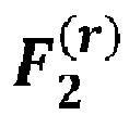
- the Rel.-15 Type-II dual-stage precoder comprises two components: A first-stage precoder denoted F 1 that is identical for all subbands and which contains the selected entries/beams selected from a Discrete Fourier Transform - based codebook (DFT-based codebook), and a second stage precoder denoted F 2 which contains the subband-dependent beam-combining coefficients of all subbands.
- F 1 A first-stage precoder denoted F 1 that is identical for all subbands and which contains the selected entries/beams selected from a Discrete Fourier Transform - based codebook (DFT-based codebook)
- F 2 which contains the subband-dependent beam-
- the feedback overhead for reporting the beam-combining coefficients increases approximately linearly with the number of subbands, and it becomes considerably large for large numbers of subbands.
- the number of beam-combining coefficients in F 2 may be drastically reduced when transforming F 2 using a small set of DFT or Discrete Cosine Transform (DCT) basis vectors into the delay domain.
- DCT Discrete Cosine Transform
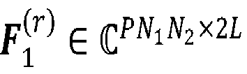
- the matrix F 1 r ⁇ C PN 1 N 2 ⁇ 2 L is the wideband first-stage precoder containing 2L spatial beams for both polarizations, which are identical for all S subbands, and F A is a diagonal matrix containing 2L wideband amplitudes associated with the 2L spatial beams, and f 2 r s is the second-stage precoder containing 2L subband (subband amplitude and phase) complex frequency-domain combining-coefficients associated with the 2L spatial beams for the s-th subband.
- V ⁇ S a compression of the combining coefficients F 2 r is achieved.
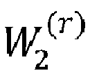
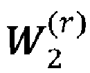
- Each complex coefficient in W 2 r in (3) is associated with a specific delay (in the transformed domain) as each DFT/DCT basis vector models a linear phase increase over the subbands.
- the number of spatial beams and indices of spatial beams may be different, identical, partially identical or non-identical over the transmission layers.
- the delays may be partially identical or non-identical over the beam. Due to different spatial beam configuration over the layers, the delay configuration may vary over the layers as well. Therefore, multiple configurations of the beam and delay configurations are possible.
- the spatial beam and delay configuration of the space-delay precoder shall be aligned with the physical structure of the radio channel.
- the radio channel is comprised of a number of clusters of scatterers associated with respective delays (see channel cluster #1, delay #1,.., channel cluster #3, delay #2 in Figure. 1 ).
- each transmit spatial beam of the gNB (beam#1, beam#2, beam#3 and beam#4 in this example) is associated with a single or few channel clusters with corresponding delays.
- Beam #1 is associated with cluster #1 and delay #1.
- Beam #2 and Beam #3 are associated with the direct Line Of Sight (LOS) channel component and with cluster #3 and delay #3.
- Beam #4 is associated with cluster #2 and delay #2. As shown, the delays of cluster #1 and cluster #2 are different and longer than the delay of cluster #3 (closest to the UE).
- the spatial DFT/DCT beams of the first stage precoder need to point in the direction of the channel clusters.
- the clusters are uniformly distributed around the gNB, and each transmit spatial beam is associated with a single or few neighbored clusters.
- each cluster is associated with a different delay.
- the number of clusters to which each spatial beam is associated with depends mainly on the beam width (which is related to the aperture size of the antenna array at the gNB). The larger the beam width (i.e., the smaller the aperture size of the antenna array) the more channel clusters are associated with the spatial beam. Therefore, the delay configuration (number of delays per beam and the values of the delays) of each spatial beam depends on the channel cluster(s) to which the spatial beam is associated with.
- each spatial beam is associated with either a single or a small set of delays.
- the transmit beams are hence “delayed” by specific delay(s) before transmission.
- the delays need to be selected in such a way that all 2 L beams are coherently combined at the UE. Note again that each delay is represented by entries of a DFT/DCT vector which models a linear phase increase over the subbands.
- the selection of the delays for a spatial beam is therefore identical to a selection of DFT/DCT vectors. Due to the delay distribution of the channel clusters, it should be understood that the delays associated with one spatial beam might be different to the delays associated with another spatial beam. Similarly, the delay configuration (number of delays and the delay values) may be different for different beams. Different delay configurations are discussed in detail in applicant's documents [2], [3], [7]. Note that document [7] has not yet been published when the present application is filed and hence [7] is not to be considered prior art for the subject matter of the claims and teachings of the present application.
- a matrix containing all selected DFT/DCT vectors of all configured spatial beams may be used to form a common matrix for the transformation.
- the common transformation matrix contains all the selected DFT/DCT vectors of all beams.
- the combining coefficients associated with a beam contain few non-zeros coefficients only for the DFT/DCT vectors it is associated with and zeros elsewhere.
- the complex combining coefficients in matrix W 2 r in (3) may contain a large number of values which are close to zero.
- An object of embodiments herein is to provide methods and apparatuses in the form a User Equipment (UE) and a radio base station or network node or gNB respectively for reducing (CSI) feedback overhead by employing efficient amplitude and phase quantization and reporting of coefficients in a communications network that employs beamforming and/or MIMO operation. Further, the present embodiments address the problem of how to efficiently quantize and report the transformed combining coefficients.
- UE User Equipment
- gNB network node or gNB
- a method performed by a UE for reducing feedback overhead related to CSI in a communications network employing MIMO operation :
- an apparatus in the form of UE for reducing feedback overhead in a communications network comprising a processor and a memory, said memory containing instructions executable by said processor whereby said UE is operative to perform any one of the subject matter of method claims 1-12.
- a carrier containing the computer program wherein the carrier is one of a computer readable storage medium; an electronic signal, optical signal or a radio signal.
- a radio network node gNB for reducing feedback overhead related to Channel State Information, CSI, in a communications network employing Multi Input Multi Output, MIMO operation, the method comprising: receiving, from a UE, a report including information related to at least one phase value or at least one amplitude value or at least one phase value and an amplitude value each quantized coefficient which is quantized with a least one bit by a UE; wherein each entry corresponding to a (i, j)-th combining coefficient of a precoder matrix W 2 r , is decomposed by the UE into at least two coefficients, wherein r denotes a r-th transmission layer; said (i, j)-th combining coefficient is associated with a i-th beam and a j-th delay, and wherein each combining coefficient is associated with an amplitude and a phase-information.
- a radio network node or gNB for reducing feedback overhead in a communications network
- the radio network node comprising a processor and a memory, said memory containing instructions executable by said processor whereby said the radio network node is operative to perform the subject-matter of an yone of claims 14-16.
- a carrier is also provided containing the computer program wherein the carrier is one of a computer readable storage medium; an electronic signal, optical signal or a radio signal.
- Type-1 and Type-2 codebook have been standardized for the CSI feedback in the support of advanced MIMO operation.
- the present embodiments address the problem of how to efficiently quantize and report the transformed combining coefficients in order to reduce CSI feedback overhead in a communications network employing beamforming.
- Each complex coefficient in W 2 r in (3) is associated with a specific delay (in the transformed domain) as each DFT/DCT basis vector models a linear phase increase over the subbands.
- W 2 r contains complex-combining coefficients.
- the values of N 1 and N 2 are design parameters and may be included in a configuration of an antenna array at a gNB, which antenna array may for example be dual-polarized, although the embodiments herein are not restricted to dual-polarized antenna arrays.
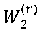
- An approach for quantizing the amplitude and phase values of the coefficients in W 2 r is to quantize directly each amplitude and phase value with N 1 and N 2 bits, respectively.
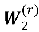
- an approach according to an exemplary embodiment is to feedback only the amplitude and phase-information of the non-zero coefficients of matrix W 2 r and to indicate by a bitmap the indices of the reported coefficients.
- the first bit in the bitmap may be associated with the first coefficient, the second bit with the first coefficient of matrix W 2 r and so on.
- the corresponding coefficient amplitude and/or phase
- the overhead for reporting the combining coefficients may be largely reduced; however, the number of feedback bits is not fixed and may vary for each reporting instance. (see below how he number of feedback bits may be fixed).
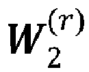
- the receiver may be configured to feedback the amplitude and/or phase values of the K strongest coefficients of matrix W 2 r , where the value of the parameter K is configurable by the gNB.
- the K strongest coefficients may be represented by the K entries having the highest amplitude (or power) over the elements in W 2 r .
- the UE may be configured to report the phase and/or amplitude values of the associated coefficient b i,j to the gNB.
- the bitmap may hence contain no more than K '1's.
- the receiver e.g. a UE or another gNB
- the receiver may be configured to select K u strongest coefficients per row/beam out of matrix W 2 r , where the parameters K u may be configurable by the gNB (transmitter). Note that the values of K u may be identical for a set of rows/beams of matrix W 2 r . In such a case, a single parameter R may be used to configure multipole parameters K d .
- the receiver may be configured to select K d strongest coefficients per column/delay out of matrix W 2 r , where the parameters K d may be configurable by the gNB. Note that the values of K d may also be identical for a set of columns/delays of matrix W 2 r . In such a case, a single parameter O is used to configure multiple parameters K d .
- the receiver may be configured to report only the amplitude and/or phase information for a subset of the coefficients in W 2 r .
- the subset of coefficients in W 2 r may contain the combining coefficients associated with the "strongest" beams and/or "strongest” delays.
- the rows and/or columns of W 2 r may be assumed to be ordered in such a way that the combining-coefficients satisfy: ⁇ ⁇ j W 2 r 1 , j ⁇ ⁇ ⁇ j W 2 r 2 , j ⁇ ⁇ ⁇ ⁇ j W 2 r U , j and/or ⁇ ⁇ i W 2 r i , 1 ⁇ ⁇ ⁇ i W 2 r i , 2 ⁇ ⁇ ⁇ ⁇ i W 2 r i , D .
- the receiver maybe configured to report the amplitude and/or phase information of the coefficients associated with the D "strongest" delays.
- the receiver may be configured to report the amplitude and/or phase information of the coefficients associated with the U ' "strongest” beams and D "strongest” delays.
- b i,j is the complex-valued normalized combining-coefficient associated with the i-th beam and j-th delay
- a i is a real-valued coefficient representing a common amplitude for the combining coefficients for all delays associated with the i-th beam. Note that the calculation of the values a i is implementation specific.
- the receiver may be configured to represent the combining coefficients or only a set of the combining coefficients in W 2 r by scheme 1, scheme 2, or scheme 3. Note that the proposed schemes can also be combined for representing the combining coefficients. For example, the receive may be configured to represent a first set of combining coefficient of W 2 r by scheme 1 or scheme 2, and a second set of the combining coefficients of W 2 r by scheme 3.
- the coefficients are quantized separately in according with an embodiment.
- the main advantage of the above decomposition schemes is that the amplitude values of b i,j may be quantized with a significantly lower number of bits than the amplitude values of the combining-coefficients in W 2 r . Therefore, the feedback overhead for reporting the amplitude values of the entries in W 2 r advantage be significantly reduced when applying one of the proposed decomposition schemes.
- the receiver may be configured to quantize the real-valued coefficients a i (and/or d j ) equally with N a (and/or N d ) bits.
- Each complex-valued coefficient b i,j may be quantized with N b, 1 and N b, 2 bits for the amplitude and phase, respectively, where N b, 1 may be lower than N b, 2 .
- the amount of feedback that may be saved by scheme 1 may be given by U ( D ( N a - N b , 1 ) - N a ) bits.
- U D ( N a - N b , 1 ) - N a ) bits.
- D delays
- N a 4
- N b, 1 2
- a total of 32 bits may be saved for the amplitude and phase reporting compared to the direct quantization of the entries in W 2 r .
- the UE may be configured to report only the phase values, only the amplitude values, or the amplitude and phase values of the quantized non-zero coefficients b i,j .
- the receiver may be configured to report in addition to the amplitude and/or phase information a bitmap, where each bit in the bitmap is associated with a coefficient b i,j .
- the first bit may be associated with coefficient b 1,1 , the second bit with coefficient b 1,2 , etc.
- the UE may report the phase and/or amplitude values of the associated coefficient b i,j to the gNB.
- the bitmap may hence contain P "1"'s, where P corresponds to the number of non-zero coefficients b i,j .
- the UE may be configured to report only the phase values, only the amplitude values, or the amplitude and phase values of the K strongest coefficients of matrix W 2 r , where the value of the parameter K is configurable by the gNB.
- the K strongest coefficients may be represented by the K entries having the highest amplitude (or power) over the elements in W 2 r .
- the receiver may be configured to report in addition to the K amplitude and/or phase information a bitmap, where each bit in the bitmap is associated with a coefficient b i,j .
- the first bit may be associated with coefficient b 1,1 , the second bit with coefficient b 1,2 , etc.
- the UE may report the phase and/or amplitude values of the associated coefficient b i,j to the gNB.
- the bitmap may hence contain K "1"'s.
- the UE may report only the amplitude and/or phase information with respect to the non-zero coefficients of the quantized matrix W 2 r .
- the bitmap may then contain less than K "1"'s.
- the amount of feedback required for reporting the amplitude and phase information is given (for scheme 3) by UN a + DN d + K ( N b, 1 + N b, 2 ) bits for the amplitude and phase information of W 2 r and UD bits for the bitmap.
- a total of ( UD - K )( N b, 1 + N b, 2 ) - UD bits may be saved compared to the case of reporting the amplitude and phase information of all coefficients in W 2 r to the gNB.
- the receiver may be configured to select K u strongest coefficients per row/beam out of matrix W 2 r , where the parameters K u may be configurable by the gNB. Note that the values of K u may be identical for a set of rows/beams of matrix W 2 r . In such a case, a single parameter R may be used to configure multipole parameters K d .
- the receiver may be configured to select K d strongest coefficients per column/delay out of matrix W 2 r , where the parameters K d may be configurable by the gNB. Note that the values of K d can also be identical for a set of columns/delays of matrix W 2 r . In such a case, a single parameter O is used to configure multiple parameters K d .
- Figure 2 and Figure 3 show the amplitude distribution of the combining coefficients in matrix W 2 r and the amplitude distribution of coefficients b i,j when applying the proposed third decomposition scheme according to previously described embodiment.
- the coefficients b i,j may be efficiently represented by only two quantization levels in contrast to combining coefficients in matrix W 2 r .
- the amplitude information of the coefficients b i,j can therefore be quantized using only one bit for the amplitude values.
- bits in the bitmap then directly correspond to the two quantization levels of the amplitude values of the coefficients b i,j and an additional report of the amplitude values of b i,j is not required.
- N b, 1 1
- the amount of feedback for reporting the phase values is drastically reduced as well, since a reporting of the phase values associated with zero amplitude coefficients is not required.
- the same quantization levels may also be used for scheme 1 and scheme 2 for quantizing coefficients b i,j .
- the receiver may be configured to apply different quantization levels for the phase values of the coefficients b i,j .
- the receiver may be configured to use N b , 2 ′ bits for the phase values associated with the non-zero coefficients and the U' strongest beams and N b , 2 " bits for the phase values associated with the non-zero coefficients and the remaining beams, where N b , 2 ′ > N b , 2 " .
- the DFT/DCT vectors are selected from a set of predefined DFT/DCT basis vectors, where each DFT/DCT basis vector is associated with an index. For example, when there are S DFT/DCT basis vectors, the first DFT/DCT basis vector is associated with a first index ("1"), the second DFT/DCT basis vector is associated with a second index ("1"), and the last DFT/DCT basis vector is associated with the index ("S").
- D ⁇ log 2 ( S ) ⁇ feedback bits are required.
- the receiver may be configured to report a bitmap, where each bit in the bitmap is associated with an index "d" from the set of basis vectors.
- the first bit may be associated with index 1, the second bit with index 2, etc.
- a “1" in a bitmap at position "d" indicates then the selection of the DFT/DCT vector associated with the index "d".
- the amplitude and phase values of the leading beam when the reported bitmap is comprised of a "1" at position "1", then the amplitude and phase values of the leading beam must be considered as follows: A "1" at position 1 of the bitmap indicates that the amplitude and phase of the combining coefficient of the leading beam associated with index "1" are given by 1 and 0, respectively, and are not reported. The amplitude and phase values of the remaining combining coefficients of the leading beam associated with other indices are given by 0 and 0, respectively, and are not reported. The amplitude and phase associated with the leading beam are known at the gNB.
- the matrix A ( r ) contains the values of the "average" amplitudes of the rows/beams of the combining coefficients of matrix F 2 r .
- the matrix B ( r ) is a normalization matrix that forces the S combining coefficients in the row of matrix F ⁇ 2 r which are associated with the leading beam to be "1". Note that the leading beam is associated with the highest "wideband" amplitude coefficient of matrix A ( r ) .
- W 2 r A r W ⁇ 2 r C r with W ⁇ 2 r ⁇ C 2 L ⁇ V containing 2 L ⁇ V complex-combining coefficients associated with the V basis vectors in matrix K F r ⁇ C V ⁇ S (see eqation (3))
- C ( r ) is a V ⁇ V diagonal matrix containing the "common" amplitude values of the V basis vectors.
- the receiver (or e.g. the UE) may be configured to report or not to report the S coefficients of the diagonal matrix B ( r ) using N B bits per coefficients.
- the transmitter e.g. the gNB
- FIG. 4 there is illustrated a flowchart of a method performed by a UE 500 for reducing feedback overhead related to CSI in a communications network employing MIMO operation, the method comprises: (401) decomposing each entry corresponding to a (i, j)-th combining coefficient of a precoder matrix, W 2 r , into at least two coefficients, wherein r denotes a r-th transmission layer; said (i, j)-th combining coefficient is associated with a i-th beam and a j-th delay, and wherein each combining coefficient is associated with an amplitude and a phase-information;
- the UE 500 comprises a processor 510 or processing circuit or a processing module or a processor or means 510; a receiver circuit or receiver module 540; a transmitter circuit or transmitter module 550; a memory module 520 a transceiver circuit or transceiver module 530 which may include the transmitter circuit 550 and the receiver circuit 540.
- the UE 500 further comprises an antenna system 560 which includes antenna circuitry for transmitting and receiving signals to/from at least a radio network node or gNB.
- the antenna system may employ beamforming as previously described.
- the UE 500 may operate in any radio access technology including 2G, 3G, 4G or LTE, LTE-A, 5G, WLAN, and WiMax etc. that support beamforming technology.
- the processing module/circuit 510 includes a processor, microprocessor, an application specific integrated circuit (ASIC), field programmable gate array (FPGA), or the like, and may be referred to as the "processor 510."
- the processor 510 controls the operation of the network node 500 and its components.
- Memory (circuit or module) 520 includes a random access memory (RAM), a read only memory (ROM), and/or another type of memory to store data and instructions that may be used by processor 510.
- RAM random access memory
- ROM read only memory
- the UE 500 in one or more embodiments includes fixed or programmed circuitry that is configured to carry out the operations in any of the embodiments disclosed herein.
- the UE 500 includes a microprocessor, microcontroller, DSP, ASIC, FPGA, or other processing circuitry that is configured to execute computer program instructions from a computer program stored in a non-transitory computer-readable medium that is in, or is accessible to the processing circuitry.
- non-transitory does not necessarily mean permanent or unchanging storage, and may include storage in working or volatile memory, but the term does connote storage of at least some persistence.
- the execution of the program instructions specially adapts or configures the processing circuitry to carry out the operations disclosed herein including any one of method claims 1-12.
- the UE 500 may comprise additional components not shown in Figure 5 .
- the UE 500 is operative to: decompose each entry corresponding to a (i, j)-th combining coefficient of a precoder matrix W 2 r , into at least two coefficients, wherein r denotes a r-th transmission layer; said (i, j)-th combining coefficient is associated with a i-th beam and a j-th delay, and wherein each combining coefficient is associated with an amplitude and a phase-information; quantize, separately, each of said at least two coefficients with a least one bit, and reporting information related to at least one phase value or at least one amplitude value or at least one phase value and an amplitude value of said quantized coefficient.
- the UE (500) is configured to represent the combining coefficients or only a set of the combining coefficients in W 2 r by the first scheme, the second scheme, or the third scheme.
- the method for reducing feedback overhead related to CSI in the communications network employing MIMO operation comprises: receiving, from a UE 500 a report including information related to at least one phase value or at least one amplitude value or at least one phase value and an amplitude value each quantized coefficient which is quantized with a least one bit by a UE 500; wherein each entry corresponding to a (i, j)-th combining coefficient of a precoder matrix W 2 r , is decomposed by the UE 500 into at least two coefficients, wherein r denotes a r-th transmission layer; said (i, j)-th combining coefficient is associated with a i-th beam and a j-th delay, and wherein each combining coefficient is associated with an amplitude and a phase-information;
- the method comprises configuring the UE to feedback the amplitude and/or phase values of K strongest coefficients of matrix W 2 r , wherein the value of K is configurable by radio network node (700) or the gNB.
- the method comprises configuring the UE comprises configuring the UE to select K u strongest coefficients per row/beam out of matrix W 2 r , where the parameters K u is configurable by the radio base station or gNB.
- the method comprises configuring the UE to select K d strongest coefficients per column/delay out of matrix W 2 r , where the parameters K d is configurable by the radio base station (700) or gNB.
- the method comprises configuring the UE to report only the amplitude and/or phase information for a subset of the coefficients in W 2 r .
- the method comprises configuring the UE to represent the combining coefficients or only a set of the combining coefficients in W 2 r by the first schemeor the second scheme or the third scheme.
- the method comprises configuring the UE to quantize the real-valued coefficients a i (and/or d j ) equally with N a (and/or N d ) bits, wherein a i is a real-valued coefficient representing a common amplitude for the combining coefficients for all delays associated with the i-th beam.
- the method comprises configuring the UE comprises configuring the UE to report only the phase values, only the amplitude values, or the amplitude and phase values of the quantized non-zero coefficients b i,j .
- the method comprises configuring the UE configuring the UE to report a bitmap, where each bit in the bitmap is associated with an index "d" from a set of DFT/DCT basis vectors.
- radio network node 700 Additional functions performed by the radio network node 700 has already been disclosed and need no repetition.
- some embodiments herein include a radio network node 700 for reducing feedback overhead in a communications network.
- the radio network node 700 comprises a processor 710 or processing circuit or a processing module or a processor or means 710; a receiver circuit or receiver module 740; a transmitter circuit or transmitter module 770; a memory module 720 a transceiver circuit or transceiver module 730 which may include the transmitter circuit 770 and the receiver circuit 740.
- the radio network node 700 further comprises an antenna system 760 which includes antenna circuitry for transmitting and receiving signals to/from at least network nodes and other UEs etc.
- the antenna system employs beamforming as previously described.
- the radio network node 700 may operate in any radio access technology including 2G, 3G, 4G or LTE, LTE-A, 5G, WLAN, and WiMax etc. that support beamforming technology.
- radio access technology including 2G, 3G, 4G or LTE, LTE-A, 5G, WLAN, and WiMax etc. that support beamforming technology.
- the processing module/circuit 710 includes a processor, microprocessor, an application specific integrated circuit (ASIC), field programmable gate array (FPGA), or the like, and may be referred to as the "processor 710."
- the processor 710 controls the operation of the UE 700 and its components.
- Memory (circuit or module) 720 includes a random access memory (RAM), a read only memory (ROM), and/or another type of memory to store data and instructions that may be used by processor 710.
- RAM random access memory
- ROM read only memory
- the radio network node 700 in one or more embodiments includes fixed or programmed circuitry that is configured to carry out the operations in any of the embodiments disclosed herein.
- the radio network node 700 includes a microprocessor, microcontroller, DSP, ASIC, FPGA, or other processing circuitry that is configured to execute computer program instructions from a computer program stored in a non-transitory computer-readable medium that is in, or is accessible to the processing circuitry.
- non-transitory does not necessarily mean permanent or unchanging storage, and may include storage in working or volatile memory, but the term does connote storage of at least some persistence.
- the execution of the program instructions specially adapts or configures the processing circuitry to carry out the operations disclosed herein including at least the features of method independent claim 14.
- the radio network node 700 may comprise additional components not shown in Figure 6 .
- the gNB is operative to perform any one of the subject-matter of method claims 14-16.
- radio network node 700 Additional functions performed by the radio network node 700 have already been disclosed and need not be repeated again.
- a carrier containing the computer program is also provided, wherein the carrier is one of a computer readable storage medium; an electronic signal, optical signal or a radio signal.
- the word "comprise” or “comprising” has been used in a non-limiting sense, i.e. meaning “consist at least of”. Although specific terms may be employed herein, they are used in a generic and descriptive sense only and not for purposes of limitation.
- the embodiments herein may be applied in any wireless systems including GSM, 3G or WCDMA, LTE or 4G, LTE-A (or LTE-Advanced), 5G, WiMAX, WiFi, satellite communications, TV broadcasting etc. that may employ beamforming technology.
Landscapes
- Engineering & Computer Science (AREA)
- Computer Networks & Wireless Communication (AREA)
- Signal Processing (AREA)
- Physics & Mathematics (AREA)
- Mathematical Physics (AREA)
- Radio Transmission System (AREA)
- Amplifiers (AREA)
- Mobile Radio Communication Systems (AREA)
Abstract

Description
- The present disclosure relates to the field of wireless communications, and in particular to methods and apparatuses for reducing feedback overhead (e.g. CSI feedback) by employing efficient amplitude and phase quantization and reporting of coefficients in a communications network.
- Beamforming is a crucial part of the third Generation Partnership Project (3GPP) Release (Rel.) 15 which define a New Radio (NR) access technology that enables a radio base station (also denote herein gNB) and a User Equipment (UE) to establish and adapt communication links using spatially precoded pilot signals. Important information in 5G to improve communication links and to efficiently adapt the beamforming technique is feedback reported by a gNB and/or a UE regarding Channel State Information or CSI feedback reporting.
- In Rel.-15 Type-II CSI reporting, it is assumed that dual-stage precoding is performed in the frequency domain on a per subband basis, i.e., a single precoder is calculated for a group of adjacent Physical Resource Blocks (PRBs), referred to as a 'subband'. The Rel.-15 Type-II dual-stage precoder comprises two components: A first-stage precoder denoted F 1 that is identical for all subbands and which contains the selected entries/beams selected from a Discrete Fourier Transform - based codebook (DFT-based codebook), and a second stage precoder denoted F 2 which contains the subband-dependent beam-combining coefficients of all subbands.
- The feedback overhead for reporting the beam-combining coefficients increases approximately linearly with the number of subbands, and it becomes considerably large for large numbers of subbands. To overcome the high feedback overhead of the Rel.-15 Type-II CSI reporting, it has been decided in 3GPP-Radio Access Network (RAN) standardization meeting, 3GPP RAN#81 [1]to study feedback compression schemes for the second stage precoder F 2. In several contributions [2]-[7], it has been demonstrated that the number of beam-combining coefficients in F 2 may be drastically reduced when transforming F 2 using a small set of DFT or Discrete Cosine Transform (DCT) basis vectors into the delay domain.
- Assuming a rank-R transmission and a dual-polarized antenna array at the gNB with configuration (N 1 , N 2 , 2), the Rel.-15 double-stage precoder disclosed in [8] for the s-th subband and r-th transmission layer is given by


- According to [8], the reporting and quantization of wideband amplitude matrix F A and subband combining coefficients in

- Quantization and reporting of wideband amplitudes of Matrix F A
- The wideband amplitude corresponding to the strongest beam which has an amplitude value of 1 is not reported. The wideband amplitude values associated with the remaining 2L - 1 beams are reported by quantizing each amplitude value with 3 bits.
- Quantization and reporting of amplitude and phase values of subband precoder

- The amplitudes and phase values of the coefficients associated with the first leading beam are not reported (they are assumed to be equal to 1 and 0).
- For each subband, the amplitudes of the B coefficients associated with the first B - 1 leading beams (other than the first leading beam) are quantized with 1 bit -

- The amplitude values of the remaining 2L - B beams are not reported (they are assumed to be equal to 1).
- For each subband, the phase values of the B - 1 coefficients associated with the first B - 1 leading beams (other than the first leading beam) are quantized with 3 bits.
- The phase values of the remaining 2L - B beams are quantized with 2 bits.
- The number of leading beams for which the subband amplitude is reported is given by B = 4, 4 or 6 when the total number of configured spatial beams L = 2, 3, or 4, respectively.
- Collecting the precoders F (r)(s) for all S subbands in a matrix F (r), we obtain [2,3,7]

- Then the second-stage precoder


- By considering a transformation on the subband precoder



- The number of spatial beams and indices of spatial beams may be different, identical, partially identical or non-identical over the transmission layers.
- In addition, with respect to the spatial beams, the delays may be partially identical or non-identical over the beam. Due to different spatial beam configuration over the layers, the delay configuration may vary over the layers as well. Therefore, multiple configurations of the beam and delay configurations are possible. However, the spatial beam and delay configuration of the space-delay precoder shall be aligned with the physical structure of the radio channel. The radio channel is comprised of a number of clusters of scatterers associated with respective delays (see
channel cluster # 1,delay # 1,..,channel cluster # 3,delay # 2 inFigure. 1 ). - In the example of
Figure 1 , each transmit spatial beam of the gNB (beam# 1,beam# 2,beam# 3 andbeam# 4 in this example) is associated with a single or few channel clusters with corresponding delays.Beam # 1 is associated withcluster # 1 anddelay # 1. Beam #2 and Beam #3 are associated with the direct Line Of Sight (LOS) channel component and withcluster # 3 anddelay # 3.Beam # 4 is associated withcluster # 2 anddelay # 2. As shown, the delays ofcluster # 1 andcluster # 2 are different and longer than the delay of cluster #3 (closest to the UE). - In order to capture a significant portion of the energy of the radio channel at the UE, the spatial DFT/DCT beams of the first stage precoder need to point in the direction of the channel clusters. In a typical channel setting the clusters are uniformly distributed around the gNB, and each transmit spatial beam is associated with a single or few neighbored clusters. Moreover, due to the uniform distribution of the channel clusters, each cluster is associated with a different delay. The number of clusters to which each spatial beam is associated with depends mainly on the beam width (which is related to the aperture size of the antenna array at the gNB). The larger the beam width (i.e., the smaller the aperture size of the antenna array) the more channel clusters are associated with the spatial beam. Therefore, the delay configuration (number of delays per beam and the values of the delays) of each spatial beam depends on the channel cluster(s) to which the spatial beam is associated with.
- For the transformed precoder, each spatial beam is associated with either a single or a small set of delays. The transmit beams are hence "delayed" by specific delay(s) before transmission. The delays need to be selected in such a way that all 2L beams are coherently combined at the UE. Note again that each delay is represented by entries of a DFT/DCT vector which models a linear phase increase over the subbands.
- The selection of the delays for a spatial beam is therefore identical to a selection of DFT/DCT vectors. Due to the delay distribution of the channel clusters, it should be understood that the delays associated with one spatial beam might be different to the delays associated with another spatial beam. Similarly, the delay configuration (number of delays and the delay values) may be different for different beams. Different delay configurations are discussed in detail in applicant's documents [2], [3], [7]. Note that document [7] has not yet been published when the present application is filed and hence [7] is not to be considered prior art for the subject matter of the claims and teachings of the present application.
- When different DFT/DCT vectors are used per spatial beam, a matrix containing all selected DFT/DCT vectors of all configured spatial beams may be used to form a common matrix for the transformation. The common transformation matrix contains all the selected DFT/DCT vectors of all beams. When such a matrix is used for the transformation, the combining coefficients associated with a beam contain few non-zeros coefficients only for the DFT/DCT vectors it is associated with and zeros elsewhere.
- Therefore, the complex combining coefficients in matrix

- 3GPP DRAFT; R-1812242, 3RD GENERATION PARTNERSHIP PROJECT (3GPP), MOBILE COMPETENCE CENTER; 650, ROUTES DES LUCIOLES; F-06921 SOPHIA-ANTIPOLIS CEDEX; FRANCE, RAN WG1, Spokane, USA, NOVEMBER 2018, discloses discussion on CSI enhancement in Re-16.
- 3GPP DRAFT; R-1813357, 3RD GENERATION PARTNERSHIP PROJECT (3GPP), MOBILE COMPETENCE CENTER; 650, ROUTES DES LUCIOLES; F-06921 SOPHIA-ANTIPOLIS CEDEX; FRANCE, RAN WG1, Spokane, China, NOVEMBER 2018, discloses discussion on type II CSI overhead reduction.
- An object of embodiments herein is to provide methods and apparatuses in the form a User Equipment (UE) and a radio base station or network node or gNB respectively for reducing (CSI) feedback overhead by employing efficient amplitude and phase quantization and reporting of coefficients in a communications network that employs beamforming and/or MIMO operation. Further, the present embodiments address the problem of how to efficiently quantize and report the transformed combining coefficients.
- According to an aspect of embodiments herein, there is provided a method performed by a UE for reducing feedback overhead related to CSI in a communications network employing MIMO operation:
- decomposing each entry corresponding to a (i, j)-th combining coefficient of a precoder matrix

- quantizing, separately, each of said at least two coefficients with a least one bit, and
- reporting information related to at least one phase value or at least one amplitude value or at least one phase value and an amplitude value of said quantized coefficient.
- According to another aspect of embodiments herein, there is provided an apparatus in the form of UE for reducing feedback overhead in a communications network, the UE comprising a processor and a memory, said memory containing instructions executable by said processor whereby said UE is operative to perform any one of the subject matter of method claims 1-12.
- There is also provided a computer program comprising instructions which when executed on at least one processor of the UE according to claim 13, cause at least said one processor to carry out the method according to any one of claims 1-12.
- A carrier containing the computer program, wherein the carrier is one of a computer readable storage medium; an electronic signal, optical signal or a radio signal.
- There is also provided a method performed by a radio network node gNB for reducing feedback overhead related to Channel State Information, CSI, in a communications network employing Multi Input Multi Output, MIMO operation, the method comprising: receiving, from a UE, a report including information related to at least one phase value or at least one amplitude value or at least one phase value and an amplitude value each quantized coefficient which is quantized with a least one bit by a UE;
wherein each entry corresponding to a (i, j)-th combining coefficient of a precoder matrix
- According to another aspect of embodiments herein, there is also provided a radio network node or gNB for reducing feedback overhead in a communications network, the radio network node comprising a processor and a memory, said memory containing instructions executable by said processor whereby said the radio network node is operative to perform the subject-matter of an yone of claims 14-16.
- There is also provided a computer program comprising instructions which when executed on at least one processor of the radio network node according to claim 17, cause the at least said one processor to carry out the method according to any one of claims 14-16.
- A carrier is also provided containing the computer program wherein the carrier is one of a computer readable storage medium; an electronic signal, optical signal or a radio signal.
- Several advantages with the embodiments herein are presented in the detailed part of this disclosure.
- Examples of embodiments and advantages of the embodiments herein are described in more detail with reference to attached drawings in which:
- Figure 1
- depicts an example network scenario wherein embodiments herein may be employed.
- Figure 2
- illustrates amplitude distribution of the combining coefficients in matrix

- Figure 3
- Amplitude distribution of coefficients bi,j for
scheme 3 according to an embodiment herein. - Figure 4
- illustrates a flowchart of a method performed by a UE according to some exemplary embodiments herein.
- Figure 5
- is a block diagram depicting a UE according to exemplary embodiments herein.
- Figure 6
- is a block diagram depicting a radio network node according to exemplary embodiments herein.
- In the following is presented a detailed description of the exemplary embodiments in conjunction with the drawings, in several scenarios, to enable easier understanding of the solution(s) described herein.
- As previously described, in 3GPP new radio system, two types of codebook, namely Type-1 and Type-2 codebook, have been standardized for the CSI feedback in the support of advanced MIMO operation.
- The present embodiments address the problem of how to efficiently quantize and report the transformed combining coefficients in order to reduce CSI feedback overhead in a communications network employing beamforming.
- A. Quantization and reporting of complex combining coefficients of matrix


- Each complex coefficient in
- An approach for quantizing the amplitude and phase values of the coefficients in

- For example, assuming that matrix


- In the following description, the matrix

- In order to save feedback overhead for reporting a quantized version of

- In order to fix the number of feedback bits for reporting the combining coefficients, the receiver may be configured to feedback the amplitude and/or phase values of the K strongest coefficients of matrix
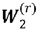
- In order to increase the flexibility of selecting the coefficients and to improve the system performance, the receiver (e.g. a UE or another gNB) may be configured to select Ku strongest coefficients per row/beam out of matrix


- Similarly, the receiver may be configured to select Kd strongest coefficients per column/delay out of matrix


- 3. Selection of submatrices of

- According to an exemplary embodiment, to reduce the overhead for reporting the coefficients in


- In an example, the receiver may be configured to report the amplitude and/or phase information of the coefficients associated with the U' "strongest" beams. The receiver may then report the amplitude and/or phase information of the coefficients:

- In another example, the receiver maybe configured to report the amplitude and/or phase information of the coefficients associated with the D "strongest" delays. The receiver may report the amplitude and/or phase information of the coefficients:

- In another example, the receiver may be configured to report the amplitude and/or phase information of the coefficients associated with the U' "strongest" beams and D "strongest" delays. The receiver may report the amplitude and/or phase information of the coefficients:

- In order to further significantly reduce the feedback overhead for reporting a quantized version of


- The first scheme decomposes the (i,j)-th combining-coefficient of matrix
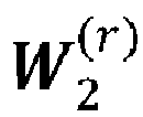

- The second scheme decomposes the (i,j)-th combining-coefficient of matrix


- The third scheme decomposes the (i,j)-th combining-coefficient of matrix


- The receiver may be configured to represent the combining coefficients or only a set of the combining coefficients in

scheme 1,scheme 2, orscheme 3. Note that the proposed schemes can also be combined for representing the combining coefficients. For example, the receive may be configured to represent a first set of combining coefficient of
scheme 1 orscheme 2, and a second set of the combining coefficients of
scheme 3. - After the decomposition of each entry of


- For example, the receiver may be configured to quantize the real-valued coefficients ai (and/or dj ) equally with Na (and/or Nd ) bits. Each complex-valued coefficient bi,j may be quantized with N b,1 and N b,2 bits for the amplitude and phase, respectively, where N b,1 may be lower than N b,2.
- For
scheme 1, assuming there are UD combining coefficients contained in matrix


scheme 1 may be given by U(D(Na - Nb ,1) - Na ) bits. For typical values for the number of beams (U), delays (D) and quantization bits (Na ) of U = 8, D = 4, Na = 4, and N b,1 = 2, a total of 32 bits may be saved for the amplitude and phase reporting compared to the direct quantization of the entries in
- For
scheme 2, assuming again there are UD combining coefficients contained in matrix
scheme 2 is given by D(U(Nd - N b,1) - Nd ) bits. For typical values for the number of beams (U), delays (D) and quantization bits (Nd ) of U = 8, D = 4, Nd = 4, and N b,1 = 2, a total of 48 bits maybe saved for the amplitude and phase reporting compared to the direct quantization of the entries in
- For
scheme 3, assuming again there are UD combining coefficients contained in matrix
scheme 3 is given by UD(Na - N b,1) - (U + D)Na bits. For typical values for the number of beams (U), delays (D) and quantization bits (Na ) of U = 8, D = 4, Na = 4, and N b,1 = 1, a total of 48 bits may be saved for the amplitude and phase information reporting compared to the direct quantization of the entries in
- To reduce the overhead for reporting the coefficients in

- To reduce the overhead for reporting the coefficients in


- The K strongest coefficients may be represented by the K entries having the highest amplitude (or power) over the elements in


- The amount of feedback required for reporting the amplitude and phase information is given (for scheme 3) by UNa + DNd + K(N b,1 + N b,2) bits for the amplitude and phase information of

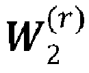
- In order to increase the flexibility of selecting the coefficients and to improve the system performance, the receiver may be configured to select Ku strongest coefficients per row/beam out of matrix

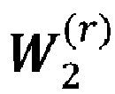
- Similarly, the receiver may be configured to select Kd strongest coefficients per column/delay out of matrix


-
Figure 2 and Figure 3 show the amplitude distribution of the combining coefficients in matrix
- As shown, when applying the proposed third decomposition scheme, the coefficients bi,j may be efficiently represented by only two quantization levels in contrast to combining coefficients in matrix

scheme 1 andscheme 2 for quantizing coefficients bi,j . - Note that the above also holds for
scheme 1 andscheme 2, i.e. the receiver may be configured with N b,1 = 1 each amplitude value may be represented by two quantization levels "a" and "b", where for example "a" and/or "b" are given by "a = 0" and "b = 1". - To further reduce the overhead for reporting the phase information of the coefficients bi,j, the receiver may be configured to apply different quantization levels for the phase values of the coefficients bi,j . For example, the receiver may configured to use


- In addition to the reporting of quantized coefficients of matrix


- Instead of directly reporting the indices of the DFT/DCT basis vectors, the receiver may be configured to report a bitmap, where each bit in the bitmap is associated with an index "d" from the set of basis vectors.
- For example, the first bit may be associated with
index 1, the second bit withindex 2, etc. A "1" in a bitmap at position "d" indicates then the selection of the DFT/DCT vector associated with the index "d". - As an example, when the number of subbands S = 13 and D = 6, the amount of feedback required to report the indices of the selected DFT/DCT vectors is given by D┌log 2(S)┐ = 24, where in contrast only S = 13 bits are required when using a bitmap.
- According to an embodiment, when the reported bitmap is comprised of a "1" at position "1", then the amplitude and phase values of the leading beam must be considered as follows:
A "1" atposition 1 of the bitmap indicates that the amplitude and phase of the combining coefficient of the leading beam associated with index "1" are given by 1 and 0, respectively, and are not reported. The amplitude and phase values of the remaining combining coefficients of the leading beam associated with other indices are given by 0 and 0, respectively, and are not reported. The amplitude and phase associated with the leading beam are known at the gNB. - As initially described, the proposed solutions are suitable for the 3GPP Rel-15 framework. Below is presented modifications (1) - (7) that are herein suggested by the inventors to the Rel. 15 framework according to some embodiments herein
- (1) The number of leading beams (B) for which the amplitude values of bi,j shall be reported to the gNB is given by B = 2L or 2L - 1 for the proposed CSI reporting using DFT/DCT transformation instead of B = 4, 4, and 6 for L = 2, 3, and 4 as in current Rel. 15, where L is the number of spatial beams configured.
- (2) All quantized amplitude and phase values of bi,j associated with the first leading beam are not reported to the gNB.
- (3) When Na = 3, the amplitude set for quantizing ai is given

- (4) When Nd = 3, the amplitude set for quantizing dj is given
uniform 
- (5) When Nd = 2, the amplitude set for quantizing dj is given {1,


- (6) The amplitude set for quantization of bi,j is given {0, 1}.
- (7) The phase set for quantizing bi,j is given by a 8PSK, or 16PSK constellation.
- It should be mentioned that differently to equation (3) above, one may introduce in the following a new transformation/decomposition of the U×S matrix
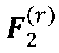


- A (r) is a real-valued U×U diagonal matrix containing U "wideband" amplitude coefficients of the respective rows/beams of matrix

-

- B (r) is a real-valued SxS diagonal matrix containing S values on its diagonal.
- The matrix A (r) contains the values of the "average" amplitudes of the rows/beams of the combining coefficients of matrix


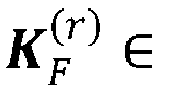

- The quantization and reporting of

- For Reporting of B (r) the receiver (or e.g. the UE) may be configured to report or not to report the S coefficients of the diagonal matrix B (r) using NB bits per coefficients. When the receiver is configured not to report the S coefficients, the transmitter (e.g. the gNB) assumes that the matrix B (r) is given by an identity matrix when reconstructing the precoder matrix. Note that the coefficients in matrix B (r) may be represented by only two quantization levels "a" and "b", where for example "a" and/or "b" are given by "

- It should be mentioned that all parameters and denoted values may take any suitable values and some or all are design parameters which when used achieve the technical effects and advantages of the embodiments described in this disclosure.
- Referring to
Figure 4 , there is illustrated a flowchart of a method performed by aUE 500 for reducing feedback overhead related to CSI in a communications network employing MIMO operation, the method comprises:
(401) decomposing each entry corresponding to a (i, j)-th combining coefficient of a precoder matrix,
- (402) quantizing, separately, each of said at least two coefficients with a least one bit, and
- (403) reporting information related to at least one phase value or at least one amplitude value or at least one phase value and an amplitude value of said quantized coefficient.
- The method performed by the UE, according to some embodiments herein are presented in the subject-matter of claims 1-12.
- In order to perform the previously described process or method steps related to the UE, embodiments herein include a UE for reducing feedback overhead in a communications network. As shown in
Figure 5 , theUE 500 comprises aprocessor 510 or processing circuit or a processing module or a processor or means 510; a receiver circuit orreceiver module 540; a transmitter circuit ortransmitter module 550; a memory module 520 a transceiver circuit ortransceiver module 530 which may include thetransmitter circuit 550 and thereceiver circuit 540. TheUE 500 further comprises anantenna system 560 which includes antenna circuitry for transmitting and receiving signals to/from at least a radio network node or gNB. The antenna system may employ beamforming as previously described. - The
UE 500 may operate in any radio access technology including 2G, 3G, 4G or LTE, LTE-A, 5G, WLAN, and WiMax etc. that support beamforming technology. - The processing module/
circuit 510 includes a processor, microprocessor, an application specific integrated circuit (ASIC), field programmable gate array (FPGA), or the like, and may be referred to as the "processor 510." Theprocessor 510 controls the operation of thenetwork node 500 and its components. Memory (circuit or module) 520 includes a random access memory (RAM), a read only memory (ROM), and/or another type of memory to store data and instructions that may be used byprocessor 510. In general, it will be understood that theUE 500 in one or more embodiments includes fixed or programmed circuitry that is configured to carry out the operations in any of the embodiments disclosed herein. - In at least one such example, the
UE 500 includes a microprocessor, microcontroller, DSP, ASIC, FPGA, or other processing circuitry that is configured to execute computer program instructions from a computer program stored in a non-transitory computer-readable medium that is in, or is accessible to the processing circuitry. Here, "non-transitory" does not necessarily mean permanent or unchanging storage, and may include storage in working or volatile memory, but the term does connote storage of at least some persistence. The execution of the program instructions specially adapts or configures the processing circuitry to carry out the operations disclosed herein including any one of method claims 1-12. Further, it will be appreciated that theUE 500 may comprise additional components not shown inFigure 5 . - As previously presented, the
UE 500 is operative to: decompose each entry corresponding to a (i, j)-th combining coefficient of a precoder matrix
- The UE is configured to decompose using a first scheme, the (i,j)-th combining-coefficient of said matrix


- The UE (500) is configured to decompose using a second scheme, the (i,j)-th combining-coefficient of matrix


- The UE (500) is configured to decompose, using a third scheme the (i,j)-th combining-coefficient of matrix


- The UE (500) is configured to represent the combining coefficients or only a set of the combining coefficients in

- Additional details relating to the functionality or actions performed by the UE have already been disclosed (see method steps performed by the UE). There is also provided a computer program comprising instructions which when executed on at least one
processor 510 of theUE 500 according to claim 13, cause theprocessor 510 to carry out the method according to any one of claims 1-12. - There is also provided a method performed by a radio base station or a radio network node or a
gNB 700 according to some exemplary embodiments:
The method for reducing feedback overhead related to CSI in the communications network employing MIMO operation comprises:
receiving, from a UE 500 a report including information related to at least one phase value or at least one amplitude value or at least one phase value and an amplitude value each quantized coefficient which is quantized with a least one bit by aUE 500; wherein each entry corresponding to a (i, j)-th combining coefficient of a precoder matrix
UE 500 into at least two coefficients, wherein r denotes a r-th transmission layer; said (i, j)-th combining coefficient is associated with a i-th beam and a j-th delay, and wherein each combining coefficient is associated with an amplitude and a phase-information; - The method comprises configuring the UE to feedback the amplitude and/or phase values of K strongest coefficients of matrix

- The method comprises configuring the UE comprises configuring the UE to select Ku strongest coefficients per row/beam out of matrix

- The method comprises configuring the UE to select Kd strongest coefficients per column/delay out of matrix

- The method comprises configuring the UE to report only the amplitude and/or phase information for a subset of the coefficients in

- The method comprises configuring the UE to represent the combining coefficients or only a set of the combining coefficients in

- The method comprises configuring the UE to quantize the real-valued coefficients ai (and/or dj ) equally with Na (and/or Nd ) bits, wherein ai is a real-valued coefficient representing a common amplitude for the combining coefficients for all delays associated with the i-th beam.
- The method comprises configuring the UE comprises configuring the UE to report only the phase values, only the amplitude values, or the amplitude and phase values of the quantized non-zero coefficients bi,j .
- The method comprises configuring the UE configuring the UE to report a bitmap, where each bit in the bitmap is associated with an index "d" from a set of DFT/DCT basis vectors.
- Additional functions performed by the
radio network node 700 has already been disclosed and need no repetition. - In order to perform the previously described process or method steps related to the radio network node, some embodiments herein include a
radio network node 700 for reducing feedback overhead in a communications network. - As shown in
Figure 6 , theradio network node 700 comprises aprocessor 710 or processing circuit or a processing module or a processor or means 710; a receiver circuit orreceiver module 740; a transmitter circuit or transmitter module 770; a memory module 720 a transceiver circuit ortransceiver module 730 which may include the transmitter circuit 770 and thereceiver circuit 740. Theradio network node 700 further comprises anantenna system 760 which includes antenna circuitry for transmitting and receiving signals to/from at least network nodes and other UEs etc. The antenna system employs beamforming as previously described. - The
radio network node 700 may operate in any radio access technology including 2G, 3G, 4G or LTE, LTE-A, 5G, WLAN, and WiMax etc. that support beamforming technology. - The processing module/
circuit 710 includes a processor, microprocessor, an application specific integrated circuit (ASIC), field programmable gate array (FPGA), or the like, and may be referred to as the "processor 710." Theprocessor 710 controls the operation of theUE 700 and its components. Memory (circuit or module) 720 includes a random access memory (RAM), a read only memory (ROM), and/or another type of memory to store data and instructions that may be used byprocessor 710. In general, it will be understood that theradio network node 700 in one or more embodiments includes fixed or programmed circuitry that is configured to carry out the operations in any of the embodiments disclosed herein. - In at least one such example, the
radio network node 700 includes a microprocessor, microcontroller, DSP, ASIC, FPGA, or other processing circuitry that is configured to execute computer program instructions from a computer program stored in a non-transitory computer-readable medium that is in, or is accessible to the processing circuitry. Here, "non-transitory" does not necessarily mean permanent or unchanging storage, and may include storage in working or volatile memory, but the term does connote storage of at least some persistence. The execution of the program instructions specially adapts or configures the processing circuitry to carry out the operations disclosed herein including at least the features of method independent claim 14. Further, it will be appreciated that theradio network node 700 may comprise additional components not shown inFigure 6 . For reducing feedback overhead related to Channel State Information, CSI, in a communications network employing Multi Input Multi Output, MIMO operation, the gNB is operative to perform any one of the subject-matter of method claims 14-16. - Additional functions performed by the
radio network node 700 have already been disclosed and need not be repeated again. - There is also provided a computer program comprising instructions which when executed on at least one
processor 710 of theradio network node 700 according to claim 17, cause the at least said oneprocessor 710 to carry out the method according to any one of claims 14-16. - A carrier containing the computer program is also provided, wherein the carrier is one of a computer readable storage medium; an electronic signal, optical signal or a radio signal.
- As evident from the detailed description presented above, several advantages are achieved by the disclosed embodiments.
- Throughout this disclosure, the word "comprise" or "comprising" has been used in a non-limiting sense, i.e. meaning "consist at least of". Although specific terms may be employed herein, they are used in a generic and descriptive sense only and not for purposes of limitation. The embodiments herein may be applied in any wireless systems including GSM, 3G or WCDMA, LTE or 4G, LTE-A (or LTE-Advanced), 5G, WiMAX, WiFi, satellite communications, TV broadcasting etc. that may employ beamforming technology.
-
- [1] Samsung, "Revised WID: Enhancements on MIMO for NR", RP-182067, 3GPP RAN#81, Gold Coast, Australia, Sept. 10 - 13, 2018.
- [2] Fraunhofer IIS, Fraunhofer HHI, "Enhancements on Type II CSI reporting scheme," R1-1806124, Busan, South Korea, May 21 - 25, 2018.
- [3] Fraunhofer IIS, Fraunhofer HHI, "Enhancements on Type-II CSI reporting," R1-1811088, Chengdu, China, Oct. 8 - 12, 2018.
- [4] Fraunhofer IIS, Fraunhofer HHI, "Space-delay versus sub-band precoding for mmWave channels," R1-1800597, Vancouver, Canada, Jan. 22-26, 2018.
- [5] Ericsson, "On CSI enhancements for MU-MIMO support," R1-1811193, Chengdu, China, October 8-12, 2018.
- [6] Huawei, HiSilicon, "Discussion on CSI enhancement for MU-MIMO," R1-1810103, Chengdu, China, October 8 - 12, 2018.
- [7] Fraunhofer IIS, Fraunhofer HHI, "Enhancements on Type II CSI reporting scheme," R1-1813130, Spokane, USA, Nov. 12 - 16, 2018.
- [8] 3GPP TS 38.214 V15.3.0, "3GPP; TSG RAN; NR; Physical layer procedures for data (Release 15)", Sept. 2018.
- [9] Nokia, Nokia Shanghai Bell, "CSI feedback overhead reduction for MU-MIMO enhancements," R1 -1813488, Nov. 12 - 16, 2018.
Claims (17)
- A method performed by a User Equipment, UE, (500) for reducing feedback overhead related to Channel State Information, CSI, in a communications network employing Multi Input Multi Output, MIMO operation, the method comprising:- (401) decomposing each entry corresponding to a (i,j)-th combining coefficient of a precoder matrix
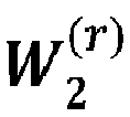 wherein the decomposed (i,j)-th combining-coefficient of said matrix
 where bi,j is a complex-valued normalized combining coefficient associated with the i-th beam and j-th delay, and ai is a real-valued coefficient representing a common amplitude for the combining coefficients for all delays associated with the i-th beam;- (402) quantizing, separately, each of said at least two coefficients with a least one bit, and- (403) reporting information related to at least one phase value or at least one amplitude value or at least one phase value and an amplitude value of said quantized coefficient.
 - The method according to claim 1, wherein the precoder matrix


- The method according to claim 1, wherein the precoder matrix

- The method according to any one of the preceding claims comprises reporting only the phase values, only the amplitude values, or the amplitude and phase values of K strongest coefficients of matrix

- The method according to claim 1 comprises applying different quantization levels for the phase values of the coefficients bi,j .
- The method according to claim 2, further comprises reporting indices of Discrete Fourier Transform / Discrete Cosine Transform, DFT/DCT vectors associated with matrix

- The method according to claim 6 comprises selecting the DFT/DCT vectors from a set of predefined DFT/DCT basis vectors, where each DFT/DCT basis vector is associated with an index.
- The method according to claim 7 comprises reporting a bitmap, where each bit in the bitmap is associated with an index "d" from the set of DFT/DCT basis vectors associated with matrix

- The method according claim 1 comprises reporting a bitmap wherein each bit in the bitmap is associated with said coefficient bi,j and when a bit is set to one, the phase and amplitude values associated with the coefficient bi,j are reported.
- The method according to claim 9 wherein the bitmap comprises K or less than K '1's.
- The method according to claim 1, comprises reporting the amplitude and phase information with respect to non-zero coefficients of the quantized matrix

- The method according to claim 1 comprises reporting information related to only the phase values, only the amplitude values, or only the amplitude and the phase values of the quantized non-zero coefficients bi,j .
- A User Equipment (500) for reducing feedback overhead related to Channel State Information, CSI, in a communications network employing Multi Input Multi Output, MIMO operation, the UE (500) comprising a processor (510) and a memory (520) containing instructions executable by said processor (510) whereby the UE (500) is operative to perform any one of the subject-matter of method claims 1-12.
- A method performed by a radio network node (700) or gNB for reducing feedback overhead related to Channel State Information, CSI, in a communications network employing Multi Input Multi Output, MIMO operation, the method comprising:receiving, from a UE (500), a report including information related to at least one phase value or at least one amplitude value or at least one phase value and an amplitude value of each quantized coefficient which is quantized with a least one bit by a UE (500);wherein each entry corresponding to a (i,j)-th combining coefficient of a precoder matrix
 wherein the decomposed (i,j)-th combining-coefficient of said matrix
 where bi,j is a complex-valued normalized combining-coefficient associated with the i-th beam and j-th delay, and ai is a real-valued coefficient representing a common amplitude for the combining coefficients for all delays associated with the i-th beam.
 - The method according to claim 14 comprises configuring the UE (500) to feedback the amplitude and/or phase values of K strongest coefficients of matrix

- The method according to claim 14 comprises receiving from a UE (500) a bitmap wherein each bit in the bitmap is associated with said coefficient bi,j and when a bit is set to one, the phase and amplitude values associated with the coefficient bi,j are reported.
- A radio network node (700) or a gNB for reducing feedback overhead related to Channel State Information, CSI, in a communications network employing Multi Input Multi Output, MIMO operation, the gNB (700) comprising a processor (710) and a memory (720) containing instructions executable by said processor (710) whereby the gNB (700) is operative to perform any one of the subject-matter of method claims 14-16.
Priority Applications (1)
| Application Number | Priority Date | Filing Date | Title |
|---|---|---|---|
| EP22159225.6A EP4047831A1 (en) | 2018-11-13 | 2018-11-13 | Methods and apparatuses for reducing feedback overhead |
Applications Claiming Priority (3)
| Application Number | Priority Date | Filing Date | Title |
|---|---|---|---|
| EP18803646.1A EP3811527B1 (en) | 2018-11-13 | 2018-11-13 | Methods and apparatuses for reducing feedback overhead |
| PCT/EP2018/081125 WO2020098924A1 (en) | 2018-11-13 | 2018-11-13 | Methods and apparatuses for reducing feedback overhead |
| EP22159225.6A EP4047831A1 (en) | 2018-11-13 | 2018-11-13 | Methods and apparatuses for reducing feedback overhead |
Related Parent Applications (2)
| Application Number | Title | Priority Date | Filing Date |
|---|---|---|---|
| EP18803646.1A Division EP3811527B1 (en) | 2018-11-13 | 2018-11-13 | Methods and apparatuses for reducing feedback overhead |
| EP18803646.1A Division-Into EP3811527B1 (en) | 2018-11-13 | 2018-11-13 | Methods and apparatuses for reducing feedback overhead |
Publications (1)
| Publication Number | Publication Date |
|---|---|
| EP4047831A1 true EP4047831A1 (en) | 2022-08-24 |
Family
ID=64316551
Family Applications (2)
| Application Number | Title | Priority Date | Filing Date |
|---|---|---|---|
| EP18803646.1A Active EP3811527B1 (en) | 2018-11-13 | 2018-11-13 | Methods and apparatuses for reducing feedback overhead |
| EP22159225.6A Pending EP4047831A1 (en) | 2018-11-13 | 2018-11-13 | Methods and apparatuses for reducing feedback overhead |
Family Applications Before (1)
| Application Number | Title | Priority Date | Filing Date |
|---|---|---|---|
| EP18803646.1A Active EP3811527B1 (en) | 2018-11-13 | 2018-11-13 | Methods and apparatuses for reducing feedback overhead |
Country Status (7)
| Country | Link |
|---|---|
| US (2) | US11223407B2 (en) |
| EP (2) | EP3811527B1 (en) |
| JP (2) | JP7214071B2 (en) |
| KR (1) | KR102633776B1 (en) |
| CN (1) | CN112514278B (en) |
| ES (1) | ES2925188T3 (en) |
| WO (1) | WO2020098924A1 (en) |
Families Citing this family (7)
| Publication number | Priority date | Publication date | Assignee | Title |
|---|---|---|---|---|
| CN113346936B (en) * | 2019-01-07 | 2022-09-13 | Oppo广东移动通信有限公司 | A codebook processing method, terminal device and network device |
| CN118199834A (en) * | 2019-01-09 | 2024-06-14 | 华为技术有限公司 | Parameter configuration method and communication device |
| WO2020142974A1 (en) * | 2019-01-10 | 2020-07-16 | Qualcomm Incorporated | Feedback for type ii channel state information |
| WO2020150854A1 (en) * | 2019-01-21 | 2020-07-30 | Qualcomm Incorporated | Feedback overhead reduction |
| WO2020150936A1 (en) | 2019-01-23 | 2020-07-30 | Qualcomm Incorporated | Precoder matrix quantization for compressed csi feedback |
| CN114337750B (en) * | 2021-12-01 | 2023-05-19 | 上海科技大学 | One-bit Quantized Output Large-Scale Antenna System Realization Method and System Device |
| CN117439709A (en) * | 2022-07-14 | 2024-01-23 | 中兴通讯股份有限公司 | Channel feedback method and device |
Family Cites Families (13)
| Publication number | Priority date | Publication date | Assignee | Title |
|---|---|---|---|---|
| WO2008021392A2 (en) * | 2006-08-17 | 2008-02-21 | Interdigital Technology Corporation | Method and apparatus for reducing a peak-to-average power ratio in a multiple-input multiple-output system |
| US7649831B2 (en) * | 2007-05-30 | 2010-01-19 | Samsung Electronics Co., Ltd. | Multi-user MIMO feedback and transmission in a wireless communication system |
| GB0800366D0 (en) * | 2008-01-09 | 2008-02-20 | Icera Inc | System and method of wireless communication |
| US8582627B2 (en) * | 2010-04-07 | 2013-11-12 | Telefonaktiebolaget Lm Ericsson (Publ) | Precode structure for MIMO precoding |
| JP5357119B2 (en) * | 2010-08-16 | 2013-12-04 | 株式会社エヌ・ティ・ティ・ドコモ | Mobile terminal device and wireless communication method |
| US9559884B2 (en) * | 2011-02-07 | 2017-01-31 | Intel Corporation | Co-phasing of transmissions from multiple infrastructure nodes |
| US9680535B2 (en) * | 2015-01-16 | 2017-06-13 | Samsung Electronics Co., Ltd. | Method and apparatus for reduced feedback FD-MIMO |
| CN107888265B (en) | 2016-09-30 | 2019-08-23 | 中兴通讯股份有限公司 | Channel information feedback method and device, terminal, base station |
| US10903887B2 (en) | 2016-11-03 | 2021-01-26 | Lg Electronics Inc. | Method for transmitting and receiving channel state information in wireless communication system and device therefor |
| US10200103B2 (en) * | 2016-11-23 | 2019-02-05 | Samsung Electronics Co., Ltd. | Method and apparatus to enable multi-resolution CSI reporting in advanced wireless communication systems |
| KR102364258B1 (en) * | 2017-03-23 | 2022-02-17 | 엘지전자 주식회사 | Method for transmitting and receiving channel state information in a wireless communication system and apparatus therefor |
| US10742290B2 (en) | 2017-04-13 | 2020-08-11 | Samsung Electronics Co., Ltd. | High-resolution CSI reporting based on unequal bit allocation in advanced wireless communication systems |
| US20180367197A1 (en) * | 2017-06-16 | 2018-12-20 | Mediatek Inc. | Method And Apparatus For Linear Combination Codebook Design And CSI Feedback In Mobile Communications |
-
2018
- 2018-11-13 CN CN201880096153.7A patent/CN112514278B/en active Active
- 2018-11-13 WO PCT/EP2018/081125 patent/WO2020098924A1/en not_active Ceased
- 2018-11-13 US US17/264,667 patent/US11223407B2/en active Active
- 2018-11-13 JP JP2021503729A patent/JP7214071B2/en active Active
- 2018-11-13 ES ES18803646T patent/ES2925188T3/en active Active
- 2018-11-13 EP EP18803646.1A patent/EP3811527B1/en active Active
- 2018-11-13 EP EP22159225.6A patent/EP4047831A1/en active Pending
- 2018-11-13 KR KR1020217002472A patent/KR102633776B1/en active Active
-
2022
- 2022-12-19 JP JP2022202147A patent/JP7650451B2/en active Active
-
2025
- 2025-09-29 US US19/343,188 patent/US20260031876A1/en active Pending
Non-Patent Citations (12)
| Title |
|---|
| "3GPP; TSG RAN; NR; Physical layer procedures for data (Release 15", 3GPP TS 38.214, September 2018 (2018-09-01) |
| ERICSSON: "On CSI enhancements for MU-MIMO support", R1-1811193, CHENGDU, CHINA, 2018 |
| FRAUNHOFER IIS ET AL: "Enhancements on Type-II CSI reporting", vol. RAN WG1, no. Chengdu, China; 20181008 - 20181012, 28 September 2018 (2018-09-28), XP051518489, Retrieved from the Internet <URL:http://www.3gpp.org/ftp/tsg%5Fran/WG1%5FRL1/TSGR1%5F94b/Docs/R1%2D1811088%2Ezip> [retrieved on 20180928] * |
| FRAUNHOFER IISFRAUNHOFER HHI: "Enhancements on Type II CSI reporting scheme", R1-1806124, BUSAN, SOUTH KOREA |
| FRAUNHOFER IISFRAUNHOFER HHI: "Enhancements on Type II CSI reporting scheme", R1-1813130, SPOKANE, USA |
| FRAUNHOFER IISFRAUNHOFER HHI: "Enhancements on Type-II CSI reporting", R1-1811088, CHENGDU, CHINA, December 2018 (2018-12-01) |
| FRAUNHOFER IISFRAUNHOFER HHI: "Space-delay versus sub-band precoding for mmWave channels", R1-1800597, VANCOUVER, CANADA, 2018 |
| HUAWEI ET AL: "Discussion on CSI enhancement", vol. RAN WG1, no. Spokane, USA; 20181112 - 20181116, 11 November 2018 (2018-11-11), XP051554124, Retrieved from the Internet <URL:http://www.3gpp.org/ftp/Meetings%5F3GPP%5FSYNC/RAN1/Docs/R1%2D1812242%2Ezip> [retrieved on 20181111] * |
| HUAWEIHISILICON: "Discussion on CSI enhancement for MU-MIMO", R1-1810103, CHENGDU, CHINA, December 2018 (2018-12-01) |
| MOTOROLA MOBILITY / LENOVO: "Type II CSI overhead reduction", vol. RAN WG1, no. Spokane, China; 20181112 - 20181116, 11 November 2018 (2018-11-11), XP051555390, Retrieved from the Internet <URL:http://www.3gpp.org/ftp/Meetings%5F3GPP%5FSYNC/RAN1/Docs/R1%2D1813357%2Ezip> [retrieved on 20181111] * |
| NOKIANOKIA SHANGHAI BELL: "CSI feedback overhead reduction for MU-MIMO enhancements", R1 -1813488, 2018 |
| SAMSUNG: "Revised WID: Enhancements on MIMO for NR", RP-182067, 3GPP RAN#81, GOLD COAST, AUSTRALIA |
Also Published As
| Publication number | Publication date |
|---|---|
| JP7214071B2 (en) | 2023-01-30 |
| EP3811527A1 (en) | 2021-04-28 |
| CN112514278B (en) | 2025-02-25 |
| WO2020098924A1 (en) | 2020-05-22 |
| JP7650451B2 (en) | 2025-03-25 |
| JP2022504006A (en) | 2022-01-13 |
| JP2023027317A (en) | 2023-03-01 |
| US20210266053A1 (en) | 2021-08-26 |
| CN112514278A (en) | 2021-03-16 |
| KR20210089633A (en) | 2021-07-16 |
| US20260031876A1 (en) | 2026-01-29 |
| ES2925188T3 (en) | 2022-10-14 |
| EP3811527B1 (en) | 2022-07-13 |
| US11223407B2 (en) | 2022-01-11 |
| KR102633776B1 (en) | 2024-02-06 |
Similar Documents
| Publication | Publication Date | Title |
|---|---|---|
| US20260031876A1 (en) | Methods and Apparatuses for Reducing Feedback Overhead | |
| EP3963733B1 (en) | Methods and apparatuses for csi reporting in a wireless communication system | |
| US12132541B2 (en) | Methods and apparatuses for feedback reporting in a wireless communications network | |
| EP2557721B1 (en) | Method and apparatus for sending precoding matrix index and performing precoding | |
| EP4040687A1 (en) | Receiver, transmitter, system and method employing space-delay precoding | |
| AU2020202343A1 (en) | Method and apparatus for reduced feedback FD-MIMO | |
| DE112009001262T5 (en) | Method and device for transmitting a plurality of data symbols | |
| Choi et al. | Advanced limited feedback designs for FD-MIMO using uniform planar arrays | |
| US12438583B2 (en) | Methods and apparatuses for reducing feedback overhead | |
| US12021591B2 (en) | Methods and apparatuses for reducing feedback overhead | |
| HK40042673B (en) | Methods and apparatuses for reducing feedback overhead | |
| HK40042673A (en) | Methods and apparatuses for reducing feedback overhead | |
| US20250373299A1 (en) | Method and apparatus for uplink signal precoding and reporting |
Legal Events
| Date | Code | Title | Description |
|---|---|---|---|
| PUAI | Public reference made under article 153(3) epc to a published international application that has entered the european phase |
Free format text: ORIGINAL CODE: 0009012 |
|
| STAA | Information on the status of an ep patent application or granted ep patent |
Free format text: STATUS: THE APPLICATION HAS BEEN PUBLISHED |
|
| AC | Divisional application: reference to earlier application |
Ref document number: 3811527 Country of ref document: EP Kind code of ref document: P |
|
| AK | Designated contracting states |
Kind code of ref document: A1 Designated state(s): AL AT BE BG CH CY CZ DE DK EE ES FI FR GB GR HR HU IE IS IT LI LT LU LV MC MK MT NL NO PL PT RO RS SE SI SK SM TR |
|
| RAP1 | Party data changed (applicant data changed or rights of an application transferred) |
Owner name: KONINKLIJKE PHILIPS N.V. |
|
| STAA | Information on the status of an ep patent application or granted ep patent |
Free format text: STATUS: REQUEST FOR EXAMINATION WAS MADE |
|
| 17P | Request for examination filed |
Effective date: 20230224 |
|
| RBV | Designated contracting states (corrected) |
Designated state(s): AL AT BE BG CH CY CZ DE DK EE ES FI FR GB GR HR HU IE IS IT LI LT LU LV MC MK MT NL NO PL PT RO RS SE SI SK SM TR |
|
| STAA | Information on the status of an ep patent application or granted ep patent |
Free format text: STATUS: EXAMINATION IS IN PROGRESS |
|
| 17Q | First examination report despatched |
Effective date: 20240827 |